116
AN-Conf/11-IP/4 Appendix APPENDIX DRAFT MANUAL ON ADVANCED SURFACE MOVEMENT GUIDANCE AND CONTROL SYSTEMS (A-SMGCS)
AN-Conf/11-IP/4Appendix
APPENDIX
DRAFT
MANUAL ONADVANCED SURFACE MOVEMENT GUIDANCE
AND CONTROL SYSTEMS (A-SMGCS)
AN-Conf/11-IP/4Appendix A-2
Foreword
The systems described in the ICAO Manual of Surface Movement Guidance and Control Systems(SMGCS), (Doc 9476) are not always capable of providing the necessary support to aircraft operations inorder to maintain required capacity and safety levels, especially under low visibility conditions. An advancedSMGCS (A-SMGCS) therefore, is expected to provide adequate capacity and safety in relation to specificweather conditions, traffic density and aerodrome layout by making use of modern technologies and a highlevel of integration between the various functionalities.
Due to the availability and development of new technologies, including automation, it is possible to increaseaerodrome capacity in low visibility conditions and on complex and high density aerodromes. In order to avoida technology-driven approach, generic operational requirements were developed (see Chapter 2) which,irrespective of the technology used, provide guidelines for the analysis and development of local requirements.
The performance requirements contained in this manual (see Chapter 4) are intended to provide a possiblesolution to safety or capacity-related problems identified so far; however, the A-SMGCS concept (seeChapter 1) is expected to evolve over a number of years as and when systems, procedures and technologyare developed.
The operational and performance requirements contained herein (see Chapters 3 and 4) are considered tobe necessary in the process of selection, development and implementation of A-SMGCS at aerodromes wherecurrent SMGCS need to be upgraded, or its introduction on aerodromes which currently have no SMGCS,but where the traffic density and/or aerodrome layout so requires.
The manual was produced to enable manufacturers and operators, as well as certifying authorities, to developand introduce A-SMGCS depending on local circumstances and taking into account global interoperabilityrequirements for international civil aviation operations.
____________________

AN-Conf/11-IP/4A-3 Appendix
TABLE OF CONTENTS
Chapter 1. Introduction . . . . . . . . . . . . . . . . . . . . . . . . . . . . . . . . . . . . . . . . . . . . . . . . . . . . . . . A-4a) Surface movement guidance and control (SMGCS) operations . . . . . . . . . . . . . . . . . . . . . . . . A-4b) Goals for improving SMGCS . . . . . . . . . . . . . . . . . . . . . . . . . . . . . . . . . . . . . . . . . . . . . . . . . A-5c) A-SMGCS concept . . . . . . . . . . . . . . . . . . . . . . . . . . . . . . . . . . . . . . . . . . . . . . . . . . . . . . . A-6
Chapter 2. Operational requirements . . . . . . . . . . . . . . . . . . . . . . . . . . . . . . . . . . . . . . . . . . . . A-82.1 General . . . . . . . . . . . . . . . . . . . . . . . . . . . . . . . . . . . . . . . . . . . . . . . . . . . . . . . . . . . . . A-82.2 System objectives and functions . . . . . . . . . . . . . . . . . . . . . . . . . . . . . . . . . . . . . . . . . . . . A-82.3 Division of responsibilities and functions . . . . . . . . . . . . . . . . . . . . . . . . . . . . . . . . . . . . . . A-92.4 Implementation related requirements . . . . . . . . . . . . . . . . . . . . . . . . . . . . . . . . . . . . . . . A-102.5 Basic functional requirements . . . . . . . . . . . . . . . . . . . . . . . . . . . . . . . . . . . . . . . . . . . . A-102.6 Supplementary requirements . . . . . . . . . . . . . . . . . . . . . . . . . . . . . . . . . . . . . . . . . . . . . A-152.7 System requirements . . . . . . . . . . . . . . . . . . . . . . . . . . . . . . . . . . . . . . . . . . . . . . . . . . . A-21
Chapter 3. Guidance on the application of the operational and performance requirements . A-233.1 System objectives and functions . . . . . . . . . . . . . . . . . . . . . . . . . . . . . . . . . . . . . . . . . . . A-233.2 Division of responsibilities and functions . . . . . . . . . . . . . . . . . . . . . . . . . . . . . . . . . . . . . A-233.3 Implementation related requirements . . . . . . . . . . . . . . . . . . . . . . . . . . . . . . . . . . . . . . . A-263.4 Basic functional requirements . . . . . . . . . . . . . . . . . . . . . . . . . . . . . . . . . . . . . . . . . . . . A-303.5 Supplementary requirements . . . . . . . . . . . . . . . . . . . . . . . . . . . . . . . . . . . . . . . . . . . . . A-413.6 System requirements . . . . . . . . . . . . . . . . . . . . . . . . . . . . . . . . . . . . . . . . . . . . . . . . . . . A-60
Chapter 4. Performance requirements . . . . . . . . . . . . . . . . . . . . . . . . . . . . . . . . . . . . . . . . . . A-644.1 System requirements . . . . . . . . . . . . . . . . . . . . . . . . . . . . . . . . . . . . . . . . . . . . . . . . . . . A-644.2 Surveillance requirements . . . . . . . . . . . . . . . . . . . . . . . . . . . . . . . . . . . . . . . . . . . . . . . A-654.3 Routing requirements . . . . . . . . . . . . . . . . . . . . . . . . . . . . . . . . . . . . . . . . . . . . . . . . . . . A-664.4 Guidance requirements . . . . . . . . . . . . . . . . . . . . . . . . . . . . . . . . . . . . . . . . . . . . . . . . . A-674.5 Control requirements . . . . . . . . . . . . . . . . . . . . . . . . . . . . . . . . . . . . . . . . . . . . . . . . . . . A-67
Chapter 5. Implementation issues . . . . . . . . . . . . . . . . . . . . . . . . . . . . . . . . . . . . . . . . . . . . . A-695.1 Introduction . . . . . . . . . . . . . . . . . . . . . . . . . . . . . . . . . . . . . . . . . . . . . . . . . . . . . . . . . A-695.2 Capacity assessment . . . . . . . . . . . . . . . . . . . . . . . . . . . . . . . . . . . . . . . . . . . . . . . . . . . A-695.3 Cost/benefit assessment . . . . . . . . . . . . . . . . . . . . . . . . . . . . . . . . . . . . . . . . . . . . . . . . A-715.4 Generic methodology for assessing capabilities of specific systems to
meet A-SMGCS requirements . . . . . . . . . . . . . . . . . . . . . . . . . . . . . . . . . . . . . . . . . . . . A-805.5 Safety assessment . . . . . . . . . . . . . . . . . . . . . . . . . . . . . . . . . . . . . . . . . . . . . . . . . . . . . A-825.6 Certification . . . . . . . . . . . . . . . . . . . . . . . . . . . . . . . . . . . . . . . . . . . . . . . . . . . . . . . . . A-86
Glossary . . . . . . . . . . . . . . . . . . . . . . . . . . . . . . . . . . . . . . . . . . . . . . . . . . . . . . . . . . . . . . . . . . A-87
Appendix A. A-SMGCS categorization . . . . . . . . . . . . . . . . . . . . . . . . . . . . . . . . . . . . . . . . . A-90Appendix B. A-SMGCS implementation levels . . . . . . . . . . . . . . . . . . . . . . . . . . . . . . . . . . A-93Appendix C. Equipment evolution for A-SMGCS . . . . . . . . . . . . . . . . . . . . . . . . . . . . . . . . A-95

AN-Conf/11-IP/4Appendix A-4
Appendix D. Target level of safety . . . . . . . . . . . . . . . . . . . . . . . . . . . . . . . . . . . . . . . . . . . . A-97Appendix E. A-SMGCS research . . . . . . . . . . . . . . . . . . . . . . . . . . . . . . . . . . . . . . . . . . . . . A-99

AN-Conf/11-IP/4A-5 Appendix
Chapter 1
Introduction
1.1 SURFACE MOVEMENT GUIDANCE AND CONTROL SYSTEM (SMGCS) OPERATIONS
1.1.1 Current SMGCS procedures are based primarily on the principle “see and be seen” to maintain spacingbetween aircraft and/or vehicles on the aerodrome movement area. However, the number of accidents andincidents during surface movements, including runway incursions, are increasing. Contributing factors includethe progressive increase in traffic, the complexity of aerodrome layouts, the increasing number of operationsthat take place in low visibility conditions and a proliferation of capacity enhancing techniques and procedures.Therefore, advanced capabilities are needed to ensure spacing when visual means are not adequate and tomaintain aerodrome capacity in all weather conditions.
1.1.2 Generally, operations at an aerodrome are dependant on air traffic controllers, pilots and vehicle driversusing visual observations to estimate the respective relative positions of aircraft and vehicles. Pilots andvehicle drivers rely on visual aids (lighting, signage and markings) to guide them along their assigned routesand to identify intersections and holding positions. During periods of low visibility, controllers must rely onpilots’ reports and surface movement radar to monitor spacing and to identify potential conflicts. Under theseconditions, pilots and vehicle drivers find that their ability to operate “see and be seen” is severely impaired.There are no prescribed separation minima, and controllers, pilots and vehicle drivers share the responsibilitythat operations will not create a collision hazard.
1.1.3 All aerodromes have some form of SMGCS. Commonly used systems that have been installed in thepast are described in the Manual of Surface Movement, Guidance and Control Systems (SMGCS)(Doc 9476). In the simplest form they consist of painted guidelines and signs and in the most advanced andcomplex systems they employ switched taxiway centre lines and stop bars. All SMGCS provide guidanceto an aircraft from the landing runway to the parking position on the apron and back to the runway used fortake-off, as well as to other movements on the aerodrome surface such as from a maintenance area to anapron, or from apron to apron. In addition, existing SMGCS provides some guidance to vehicles. Normally,control of the activities and the movement of aircraft and vehicles on the manoeuvring area rests with airtraffic control (ATC). In case of aprons, such responsibility sometimes rests with the apron management.The system may also provide guidance to, and control or regulation of, personnel authorized to be on themovement area of an aerodrome.
1.1.4 For low visibility operations, SMGCS plans prescribe the operational procedures that must be followedduring surface movements. Procedures vary from aerodrome to aerodrome depending on factors such asair traffic services (ATS) regulations and policies, organizational responsibilities, and the aerodromeconfiguration and facilities.
1.1.5 Low visibility SMGCS procedures are put into effect when the runway visual range (RVR) decreasesto a predetermined value (usually between 400 m and 600 m). Notifications are then issued to the aircraftoperators, and checklists are used to implement the low visibility procedures.

AN-Conf/11-IP/4Appendix A-6
1.1.6 Designated low visibility taxi routes may be used and depicted on aerodrome charts available to pilotsand vehicle drivers. Lighting systems, such as stop bars and runway guard lights, are used to assist ATC incontrolling access to active runways.
1.1.7 In low visibility, landing aircraft exit the runway at specific taxiways and follow the taxi instructionsfrom the ground controller.
1.1.8 Access of ground vehicles is strictly controlled during low visibility procedures, and only essentialvehicles are permitted on the movement area.
1.1.9 Currently, procedures permit aircraft to land in conditions down to zero visibility and to take off whenthe RVR is reduced to approximately 75 m. Although some States use sophisticated taxiway guidancesystems with stop bars to control movements, there are no ICAO provisions for the operation of an SMGCSwhich can provide for expedition and safety in all weather conditions.
1.2 GOALS FOR IMPROVING SMGCS
1.2.1 The following high level goals provide a basis for considering what capabilities are required, and maybe useful in developing improvements for surface movement operations:
a) controllers, pilots and vehicle drivers should be provided with systems of the same level ofperformance;
b) controllers, pilots and vehicle drivers should have clearly-defined roles and responsibilities that eliminateprocedural ambiguities that may lead to operational errors and deviations;
c) improved means of providing situational awareness should be available for controllers, pilots and vehicledrivers, taking into consideration visibility conditions, traffic density and aerodrome layout;
d) improved means of surveillance should be in place;
e) delays in ground movements should be reduced and growth in operations, including runway capacity,should be accommodated;
f) surface movement functions should be able to accommodate all classes of aircraft and necessaryvehicles;
g) improved guidance and procedures should be in place to allow:
1) safe surface operations on the aerodrome taking into consideration visibility, traffic density andaerodrome layout;
2) pilots and vehicle drivers to follow their assigned routes in an unambiguous and reliable way;
h) improved aerodrome visual aids providing guidance for surface movements should be an integratedcomponent of the system;

AN-Conf/11-IP/4A-7 Appendix
i) automation and human factors engineering should provide the linkage between the surface and terminaland en-route airspace to create seamless operations with reduced controller and pilot workload;
j) SMGCS improvements should be developed in a modular form to accommodate all aerodrome types;and
k) conflict prediction and/or detection, analysis, and resolution should be provided.
1.3 A-SMGCS CONCEPT
1.3.1 An A-SMGCS differs from an SMGCS in that it may provide a full individual service over a muchwider range of weather conditions, traffic density and aerodrome layouts. A-SMGCS are to use commonmodules in all circumstances. The modules to be used in any particular circumstances are determined by thespecific requirements of each aerodrome.
1.3.2 The use of A-SMGCS will lead to reallocation of responsibilities for various system functions. Lessreliance is placed on the ability of the pilot or control authority to provide visual surveillance. Some functionsuse automation to provide routing, guidance and control.
1.3.3 The main benefits to be accrued from implementation of A-SMGCS will be associated with, but notlimited to, low visibility surface operations. Significant improvements of aerodrome capacity can also beachieved under good visibility conditions.
1.3.4 The significant distinctions between the functions of a current SMGCS and an A-SMGCS are that thelatter should provide more precise guidance and control for all aircraft and vehicles on the movement area,and should also be able to ensure spacing between all moving aircraft and vehicles especially in conditionswhich prevent spacing being maintained visually. It is therefore important to recognize that, except wherethe total number of aircraft and vehicles permitted to operate on the movement area at any one time is keptvery low, such a task is beyond the capability of a controller even if aided by conventional surface movementradar (SMR). Therefore, A-SMGCS should provide situation awareness not only to ATC but also to thoseaircraft and vehicles that are liable to come in proximity to each other.
1.3.5 Complex traffic flows may require an A-SMGCS to function as a surface management systemproviding for the planning and management of all aircraft and authorized vehicles on the movement area,interfacing with the air traffic management (ATM) system.
1.3.6 An A-SMGCS addresses future increases in surface movement operations which would lead toincreased surface congestion and system delays unless new techniques were made available to the air trafficcontroller to reduce workload. From the flight dispatch/apron management perspective, more sharing ofinformation will be needed to manage the availability of stands/parking areas, thereby reducing taxi delaysto a minimum.
1.3.7 A-SMGCS will reduce voice communications, improve surface guidance aids and increase reliance onavionics in the cockpit to help guide the pilot to and from the runway. The ATC capability for surveillanceby electronic means would also improve. Automation will play a greater role to assist in monitoring thesurface operations.

AN-Conf/11-IP/4Appendix A-8
1.3.8 Communications will migrate into a mix of voice and data link capabilities, with automated datacommunications between system components providing situation information between the users, includingfrom the ground to the cockpit. Voice communications will continue to be used where necessary.
1.3.9 Surface guidance will include improved visual aids for automated guidance and control along theassigned route. However, for low visibility conditions, the pilot may need suitable avionics, such as a movingmap, to monitor progress and compliance with the assigned route. These avionics may also be used to displaysurface traffic information.
1.3.10 Improved ATC surveillance will provide accurate information on position and identity of all aircraftand vehicles operating on the movement area. This will be used to enhance the automated functionsassociated with conformance monitoring and conflict alert. Also, the surveillance information will be usefulin refining the traffic planning functions associated with predicting taxi throughput and arrival/departure times.
1.3.11 Automated functions will include monitoring of conformance with taxi instructions and detection ofpotential conflicts and their resolution. Automation will also be used to control ground visual aids based oncontroller and surveillance inputs. Thus, the ground visual aids will be set up for the runway configurationin use, and runway/taxiway intersections will be controlled based on precise knowledge of the location andmovement of aircraft and vehicles.
1.3.12 Surface traffic planning automation functions will be integrated with approach/departure operations.For arrivals, the sequence for each runway and stand assignment will be used to make accurate estimatesof arrival times at the stands. This information will improve aircraft handling and turn-around time. Fordepartures, engine start and push back times can be coordinated and managed to gain optimum departuresequencing, taking into account the planned route. Also, aerodrome configuration changes will be timed andimplemented more efficiently, thereby minimizing any impact on the aerodrome utilization rate.
1.3.13 Development of complex systems and the differing needs of users will require a modulardevelopment and introduction of various elements, some of which are already in place. The expectedevolutionary development of A-SMGCS and the varied needs of users will mean that not all aerodromes willintroduce all provisions described in this manual. Additionally, this manual can only outline steps in thecontinuing progress of aerodrome operations.
1.3.14 The technical standards implied in this manual are recognized to be the most demanding for the mostcritical conditions in terms of traffic density, visibility conditions and aerodrome layout. Implementation offacilities and procedures to these levels will, therefore, not be appropriate at all aerodromes. Implementationof A-SMGCS can only take place after an assessment of cost/benefit studies and consideration of evolvinguser requirements. There will be a continuing need for dialogue between the suppliers of services, themanufacturers and users, so that the operational requirements can be translated into technical requirements.
1.3.15 An A-SMGCS needs to be related to the operational conditions under which it is intended that theaerodrome should operate. Failure to provide a system appropriate to the demands placed on an aerodromewill lead to a reduced movement rate or may affect safety. It is important to recognize that complex systemsare not required and are not economical at aerodromes where visibility, aerodrome complexity, traffic densityand any combination of these factors do not present a problem for the ground movement of aircraft andvehicles.

AN-Conf/11-IP/4A-9 Appendix
____________________
AN-Conf/11-IP/4Appendix A-10
Chapter 2
OPERATIONAL REQUIREMENTS
2.1 GENERAL
2.1.1 The operational requirements stated in this manual refer to the most demanding conditions and are tobe applied depending upon visibility, traffic density, aerodrome layout and other local circumstances.
2.1.2 For a particular aerodrome, A-SMGCS is intended to mean one integrated system providing advancedsurface movement guidance and control at that aerodrome.
2.1.3 Throughout this manual, visibility conditions are those described in Appendix A.
2.1.4 The accountability for the safety of operations associated with an A-SMGCS will ultimately lie with theservice provider, airlines and the airport authority. In this manual, the term responsibility applies only to theperson or system and a designated role or function within an A-SMGCS.
2.1.5 Airport authorities allocate their apron areas to different control authorities. In some cases ATC hascomplete jurisdiction and in others some form of apron or ramp control exercises complete or partialjurisdiction on behalf of the airport authority. Whichever method of control is used, the level of serviceprovided by an A-SMGCS should be consistent from the runway to the stand and vice versa.
2.1.6 In order to resolve the problem of vehicle control/segregation on a specific stand, the concept isintroduced whereby the role of that stand may change from active to passive and vice versa. Hence, the useof movement area in this manual excludes passive stands, empty stands and those areas of the apron(s) whichare exclusively designated to vehicle movements.
2.1.7 An A-SMGCS as described in this manual requires the development of integrated human-machineinterface (HMI) suitable for such a function, leading to a reduced workload for controllers, pilots and vehicledrivers by using computers and automation, but retaining a manual control capability.
2.2 SYSTEM OBJECTIVES AND FUNCTIONS
2.2.1 In order to support optimized “gate to gate” operations, an A-SMGCS should be capable of assistingauthorized aircraft and vehicles to manoeuvre safely and efficiently on the movement area.
2.2.2 An A-SMGCS should support the following primary functions:
a) surveillance;
b) routing;

AN-Conf/11-IP/4A-11 Appendix
c) guidance; and
d) control.
Note.— Communication is considered to be an integral part of each of the primary functions.
2.2.3 In order to achieve the maximum benefits at each level of A-SMGCS implementation, a supportingplanning function should be included.
2.2.4 An A-SMGCS should be capable of operating at a specified movement rate in visibility conditions downto the aerodrome visibility operational level (AVOL).
2.2.5 When visibility conditions are reduced to below AVOL an A-SMGCS should provide for a reductionof surface movements of aircraft and vehicles to a level acceptable for the new situation.
2.2.6 The system should integrate movements to provide complete situational information to all users andprovide conflict prediction and resolution for aircraft and vehicle movements.
2.2.7 The system should be modular so that the appropriate level of service to the different aerodromes andto different areas of an aerodrome can be provided.
2.3 DIVISION OF RESPONSIBILITIES AND FUNCTIONS
2.3.1 Although the responsibilities and functions may vary, they should be clearly defined for all users of A-SMGCS.
2.3.2 An A-SMGCS should be designed so that the responsibilities and functions may be assigned to thefollowing:
a) the automated system;
b) controllers;
c) pilots;
d) vehicle drivers;
e) marshallers;
f) emergency services;
g) airport authorities;
h) regulatory authorities; and
i) security services.

AN-Conf/11-IP/4Appendix A-12
Note .— When using A-SMGCS, pilots remain responsible for the safety and control of aircraft.
2.4 IMPLEMENTATION RELATED REQUIREMENTS
2.4.1 The design principle of an A-SMGCS should permit modular enhancements. A-SMGCS for eachaerodrome will comprise a different mix of modular components dependent on operational factors ascategorized in Appendix A. For example, some modules of an A-SMGCS will be required when one or moreof the following conditions exist:
a) heavy traffic density;
b) visibility condition 2, 3 or 4; and
c) complex aerodrome layout.
2.4.2 The certification of an A-SMGCS should address the total system.
Note 1.— An A-SMGCS total system includes sub-systems, equipment and other componentsnecessary for it to perform its functions as well as operational procedures, the identification ofresponsibilities, management functions and system support facilities.
Note 2.— The addition or upgrading of existing modules will require an analysis to ensure thatthey do not affect the continued validity of the original certification. Where the continued validity ofthe original certification cannot be assured, a new certification of the complete system will be required.
2.5 BASIC FUNCTIONAL REQUIREMENTS
Note.— The interdependency of the primary A-SMGCS functions needs to be taken into accountin addressing the requirements below.
2.5.1 Surveillance
2.5.1.1 The surveillance function of an A-SMGCS should:
a) provide accurate position information on all movements within the movement area;
b) provide identification and labelling of authorized movements;
c) cope with moving and static aircraft and vehicles within the coverage area of the surveillance function;
d) be capable of updating data needed for the guidance and control requirements both in time and positionalong the route; and
e) be unaffected by operationally significant effects such as adverse weather and topographicalconditions.

AN-Conf/11-IP/4A-13 Appendix
2.5.1.2 The operational status of all surveillance equipment should be monitored by the system, and alertsshould be provided as appropriate.
2.5.1.3 All control authorities concerned should be provided with surveillance data in the required area ofthe aerodrome.
2.5.1.4 Within the required area of the aerodrome, surveillance should be provided up to an altitude so asto cover missed approaches and low level helicopter operations.
2.5.1.5 Surveillance should be provided for aircraft on approach to each runway at such a distance thatinbound aircraft can be integrated into an A-SMGCS operation so that aerodrome movements, includingaircraft departures or aircraft crossing active runways, can be managed.
2.5.1.6 A seamless transition should be provided between the surveillance for an A-SMGCS and thesurveillance of traffic in the vicinity of an aerodrome.
2.5.1.7 The A-SMGCS should detect any incursion into areas used for aircraft movement, the runway stripsand within any designated protected area as required by airport authorities. The surveillance system shouldalso continuously indicate the position of unauthorized aircraft, vehicles and obstacles in the above areas.
2.5.1.8 For aircraft and vehicles within the areas mentioned in 2.5.1.7, the surveillance function of an A-SMGCS should continuously provide information required to detect deviations from the assigned route, withan update rate sufficient to ensure an adequate response of the system.
2.5.2 Routing
2.5.2.1 Either manually or automatically, the routing function of an A-SMGCS should:
a) be able to designate a route for each aircraft or vehicle within the movement area;
b) allow for a change of destination at any time;
c) allow for a change of a route;
d) be capable of meeting the needs of dense traffic at complex aerodromes; and
e) not constrain the pilot's choice of a runway exit following the landing.
2.5.2.2 In a semi-automatic mode, the routing function should also provide the control authority with advisoryinformation on designated routes.
Note.— In a semi-automatic mode, assignment of routes is carried out by the control authority.
2.5.2.3 In an automatic mode, the routing function should also:
a) assign routes; and
b) provide adequate information to enable manual intervention;

AN-Conf/11-IP/4Appendix A-14
1) in the event of a failure; or
2) at the discretion of the control authority.
2.5.2.4 When assigning routes, an A-SMGCS should:
a) minimize taxi distances in accordance with the most efficient operational configuration;
b) be interactive with the control function to minimize crossing conflicts;
c) be responsive to operational changes (e.g. runway changes, routes closed for maintenance, temporaryhazards or obstacles etc.);
d) use standardized terminology or symbology;
e) be capable of providing routes as and when required by all authorized users; and
f) provide a means of validating routes.
2.5.3 Guidance
2.5.3.1 The guidance function of an A-SMGCS should:
a) provide guidance necessary for any authorized movement and be available for all possible routeselections;
b) provide clear indications to pilots and vehicle drivers to allow them to follow their assigned route;
c) enable all pilots and vehicle drivers to maintain situational awareness of their position on the assignedroute;
d) be capable of accepting a change of route at any time;
e) be capable of indicating routes and areas either restricted or not available for use;
f) allow monitoring of the operational status of all guidance aids; and
g) provide on-line monitoring with alerts where guidance aids are selectively switched in response torouting and control requirements.
Note.— When visibility conditions permit a safe, orderly and expeditious flow of authorizedmovements, the guidance function will primarily be based on standardized ground visual aids. Ifexpeditious flow is restricted due to reduced visibility, additional equipment or systems will be requiredto supplement visual aids in order to maintain flow rates.

AN-Conf/11-IP/4A-15 Appendix
2.5.4 Control
2.5.4.1 The control function of an A-SMGCS should:
a) have a capacity sufficient for the maximum authorized movement rate (dynamic capacity);
b) have a capacity sufficient for the aerodrome planning of requested movements for a period of up toone hour (static capacity);
c) detect conflicts and provide resolutions;
d) be able to provide longitudinal spacing to predetermined values of;
1) speeds;
2) relative directions;
3) aircraft dimensions;
4) jet blast effects;
5) human and system response times; and
6) deceleration performances.
e) provide alerts for incursions to runways and activate protection devices (e.g. stop bars or alarms);
f) provide alerts for incursions to taxiways and activate protection devices (e.g. stop bars or alarms);
g) provide alerts for incursions to critical and sensitive areas established for radio navigation aids;
h) provide alerts for incursions to emergency areas;
i) be capable of incorporating computer-aided management tools;
j) keep controllers, pilots and vehicle drivers in the decision loop;
k) control movements within a speed range such as to cover the operations in all required situations, takinginto account the type of movement;
l) be capable of allowing operations to continue in all visibility conditions down to AVOL; and
m) be capable of allocating priorities to control activities.
2.5.4.2 The control function of an A-SMGCS should also provide for:
a) sequencing of aircraft after landing, or departing aircraft, to ensure minimum delay and maximumutilization of the available capacity of the aerodrome;

AN-Conf/11-IP/4Appendix A-16
b) segregation of support and maintenance vehicles from operational activities as necessary;
c) spacing between aerodrome movements according to the prescribed minima, taking into account:
1) wake turbulence;
2) jet blast and propeller/rotor wash;
3) aircraft dimensions; and
4) different locations and layouts (runway, taxiway, apron or aircraft stand).
d) separation of movements from obstacles; and
e) separation with a prescribed minimum of all aircraft from an aircraft isolated for security reasons(Annex 14, Volume I, Chapter 3).
2.5.4.3 The following short-term alerts should be provided by the A-SMGCS within a time to enable theappropriate immediate action:
a) short-term conflict alert, whereby an alert is triggered when the predicted spacing will be belowpreset/predefined minima;
b) area penetration alert, whereby an alert is triggered when a movement likely to enter a critical orrestricted area is detected;
c) deviation alert, whereby an alert is triggered when the computed deviation will be more than thepreset/predefined maximum deviation;
d) runway incursion alert, whereby an alert is triggered when a movement likely to enter an active runway(runway strip) is detected; and
e) taxiway (or an inactive runway being used as a taxiway) or apron incursion alert, whereby an alert istriggered when a movement likely to enter a taxiway or apron in use, which does not belong to itsassigned route, is detected.
2.5.4.4 Distinctive medium-term alerts should be provided well in advance to enable the appropriateremedial action to be taken with respect to:
a) conflict prediction;
b) conflict detection; and
c) conflict resolution.
2.5.4.5 Once a conflict has been detected, an A-SMGCS should, either automatically resolve the conflictor, on request from the controller, provide the most suitable solution.

AN-Conf/11-IP/4A-17 Appendix
2.6 SUPPLEMENTARY REQUIREMENTS
2.6.1 Global risk factor
2.6.1.1 The introduction of an A-SMGCS should not result in an overall level of risk in excess of theprobability of one fatal accident per 107 operations.
2.6.2 Aircraft types
2.6.2.1 An A-SMGCS should support operations involving all aircraft types and be capable of adaptationto cater for future aircraft types.
2.6.3 Vehicles
2.6.3.1 An A-SMGCS should be capable of being used by appropriately equipped vehicles operating withinthe movement area.
2.6.3.2 Any authorized vehicle intended to be used on the aerodrome in the vicinity of the manoeuvring area,should be equipped to inform an A-SMGCS of its position.
2.6.4 Speeds and orientation
2.6.4.1 The system should be capable of supporting operations of aircraft and vehicles within the followingparameters:
a) minimum and maximum speeds for aircraft on final approach, missed approach and runways;
b) minimum and maximum speeds for aircraft on taxiways;
c) minimum and maximum speeds for vehicles; and
d) any heading.
2.6.5 Susceptibility
2.6.5.1 The system should not be affected by:
a) radio interference, including that produced by navigation, telecommunications and radar facilities(including airborne equipment);
b) signal reflections and shadowing caused by aircraft, vehicles, buildings, snow banks or other raisedobstacles (fixed or temporary) in or near the aerodrome; and
c) meteorological conditions or any state of the aerodrome resulting from adverse weather in whichoperations would otherwise be possible.

AN-Conf/11-IP/4Appendix A-18
2.6.6 Reference system
2.6.6.1 An A-SMGCS should be referenced to the World Geodetic System (WGS-84).
2.6.6.2 A common reference point on aircraft and vehicles should be used in A-SMGCS.
2.6.7 Planning
2.6.7.1 In order to support the primary functions (surveillance, routing, guidance and control), the planningfacilities of an A-SMGCS should provide for:
a) strategic planning which will indicate the predicted traffic situation for chosen times in excess of 20minutes in advance;
b) pre-tactical planning which will indicate the predicted traffic situation at a chosen time up to 20 minutesin advance; and
c) tactical planning which will indicate the present traffic situation.
2.6.7.2 Planning facilities should include methods of predicting an aerodrome capacity and indication ofstart-up times for traffic to meet this capacity.
Note 1.— This capacity assessment is to be based on factors such as weather conditions,serviceability of equipment, closure of sections of movement area, etc.
Note 2.— Additional elements to be included in the capacity assessment will be the need foroperational activity of the movement area, such as surface inspections, friction measurement, snowclearance, etc.
Note 3.— The implementation of A-SMGCS requires the designation of routes that ensure the safeand efficient movement of aircraft and vehicles. The route issued for any movement will be dependenton strategic, pre-tactical and tactical considerations that will be addressed within the over-all planningfunction.
2.6.8 Recording
2.6.8.1 Selected data on communications control activity and display information should be recorded foraccident and incident investigation.
2.6.8.2 There should be a function to provide direct replay of recorded data within the operational system,as part of the requirement for immediate checking of suspect equipment and initial incident investigation.
2.6.9 System failures
2.6.9.1 Equipment which shows control data should both be fail-safe and fail-soft.
Note.— The term “fail-safe” in this context means that sufficient redundancy is provided to carrydata to the display equipment to permit some components of the equipment to fail without any resultant

AN-Conf/11-IP/4A-19 Appendix
loss of data displayed. The term “fail-soft” means that the system is so designed that, even ifequipment fails to the extent that loss of some data occurs, sufficient data remain on the display toenable the controller to continue operations.
2.6.9.2 In case of a failure of an element of an A-SMGCS, the effect should be such that the status isalways in the “safe” condition.
2.6.9.3 All critical elements of the system should be provided with timely audio and visual indication offailure.
2.6.9.4 An A-SMGCS should be self restartable. The recovery times should be a few seconds.
2.6.9.5 The restart of an A-SMGCS should include the restoration of pertinent information on actual trafficand system performance.
2.6.10 Aerodrome considerations
2.6.10.1 An A-SMGCS should be capable of accommodating any change in the layout of the aerodrome(runways, taxiways and aprons).
2.6.11 Pilot considerations
2.6.11.1 The pilot should be provided with the following:
a) information on location and direction at all times;
b) continuous guidance and control during the landing roll-out, taxiing to the parking position and from theparking position to the runway-holding position, to line up at any take-off position and the take-off roll;
c) indication of the route to be followed, including changes in direction and indication of stops;
d) guidance in parking, docking and holding areas;
e) indication of spacing from preceding aircraft, including speed adjustments;
f) indication of spacing from all aircraft, vehicles and obstacles in visibility condition 4;
g) indication of the required sequencing;
h) information to prevent the effects of jet blast and propeller/rotor wash;
i) identification of areas to be avoided;
j) information to prevent collision with other aircraft, vehicles or known obstacles;
k) information on system failures affecting safety;
l) the location of active runways;

AN-Conf/11-IP/4Appendix A-20
m) alert of incursion onto runways and taxiways; and
n) the extent of critical and sensitive areas.
Note.— Most of the foregoing requirements may be satisfied by ground visual aids.
2.6.12 Vehicle driver considerations
2.6.12.1 The vehicle driver should be provided with the following:
a) information on location and direction at all times;
b) indication of the route to be followed;
c) guidance along the route being followed or to remain within designated areas;
d) information, and control when and where appropriate, to prevent collision with aircraft, vehicles andknown obstacles; and
e) alert of incursions into unauthorized areas.
2.6.12.2 In addition to 2.6.12.1, the drivers of emergency and operational vehicles should be provided with:
a) capability to locate the site of an emergency within the displayed range of the system; and
b) information on special priority routes.
Note.— Most of the foregoing requirements may be satisfied by ground visual aids.
2.6.13 Apron management considerations
2.6.13.1 The following information should be available to the apron management services:
a) information on the identity, position and progress of aircraft including aircraft under tow;
b) information on the identity, position and progress of vehicles whose movements might conflict withaircraft movements;
c) information on the presence of obstacles or other hazards;
d) information on the operational status of elements of the system; and
e) facilities appropriate to the control to be exercised.

AN-Conf/11-IP/4A-21 Appendix
2.6.14 Automation
2.6.14.1 Where automation is available the automated systems should demonstrate an acceptable level ofHMI efficiency.
2.6.14.2 The design of an A-SMGCS should make it possible to make a distinction in the system elementsand functions of the system between:
a) system assistance in the decision-making process;
b) system advice on the decisions taken; and
c) provision directly to the users of the decisions taken by the system.
2.6.14.3 Automated guidance should not be used by the system if aircraft control, conflict detection andconflict alert resolution are not available.
2.6.14.4 If the system integrity degrades, it should automatically alert all users and should have the capabilityto transfer automated functions to the controllers in an easy and safe way.
2.6.14.5 Without automation it may not be possible to meet some operational requirements. Automation offunctions can be applied to various parts of an A-SMGCS such as:
a) identification of aircraft and vehicles;
b) tracking and labelling of targets;
c) route assignment;
d) guidance and control;
e) runway incursion detection;
f) unauthorized intruder detection;
g) conflict prediction;
h) conflict detection;
i) conflict resolution;
j) alert indication;
k) indication of appropriate brightness setting for visual aids; and
l) stand allocation.

AN-Conf/11-IP/4Appendix A-22
Note.— Automation validation processes are expected to encompass all environmental andfailure conditions including a reversion to manual control.
2.6.15 Human-machine interface (HMI)
2.6.15.1 The operation of an A-SMGCS should not interfere with other ATC responsibilities.
2.6.15.2 The human-machine interface with A-SMGCS should:
a) maintain a balance between the human and the machine functions;
b) permit the human to retain the power to make decisions as to those functions for which the human isresponsible; and
c) provide for a balanced mix of visual, audio and tactile inputs and responses.
2.6.15.3 Input devices for the controllers should be functionally simple involving the controllers in a minimumnumber of input actions.
2.6.15.4 Displays and indicators should be possible to view in all ambient light levels typical of an aerodromecontrol tower environment.
2.6.15.5 Account should be taken of the ability of the flight crew and vehicle drivers to respond to theguidance and control indications of the system.
2.6.15.6 For pilots and vehicle drivers, the system should provide the essential routing, guidance and controldata in a standardized form that at all times is conspicuous, legible, comprehensible and credible.
2.6.15.7 Guidance should be implemented in such a way as to minimize the pilots’/vehicle drivers’ head downtime, while maximizing the use of visual cues.
2.6.15.8 For control staff, the system should have interfaces that allow them to manage the routing, guidanceand control functions in an efficient and safe manner.
2.6.16 Interfaces
2.6.16.1 In order to fully benefit from an A-SMGCS by all parties concerned, the system should be capableof interfacing with the following:
a) air traffic management (ATM), including:
1) arrival and departure management;
2) arrival and departure coordination;
3) optimized start up sequence and times;
4) optimized push back sequence and times; and

AN-Conf/11-IP/4A-23 Appendix
5) integrated initial flight plan processing system, central flow management unit, etc.
b) aerodrome management systems;
c) existing and future ATS systems;
d) MET systems;
e) visual aids;
f) existing and future avionics;
g) aerodrome handling systems;
h) aircraft operators;
i) emergency authorities;
j) police/security authorities; and
k) other customers or users.
2.6.16.2 The data interchange between systems should be made in a standardized format.
2.6.16.3 An A-SMGCS should enable controllers, pilots and vehicle drivers to interface and functionefficiently. These operators should also be capable of interfacing with other systems.
2.7 SYSTEM REQUIREMENTS
2.7.1 Accuracy
2.7.1.1 In specifying the positional accuracy parameters for an A-SMGCS, the requirements for the primaryfunctions and their interdependencies should be considered.
2.7.1.2 For the surveillance function, the allowable error in the reported position should be consistent withthe requirements set by the guidance and control functions.
2.7.1.3 For the guidance function, the allowable positional errors should be similar for visual or electronictaxi guidance. However, in visibility conditions where electronic guidance is required, in specifying theallowable errors, taxiway widths and aircraft main gear wheel tracks should be considered.
2.7.2 Update rate
2.7.2.1 Where appropriate, the update rate of a module on an A-SMGCS should be adequate for therequired operational performance.

AN-Conf/11-IP/4Appendix A-24
2.7.3 Integrity
2.7.3.1 The system design should preclude failures that result in erroneous data for operationally significanttime periods.
2.7.3.2 The system should have the ability to provide a continuous validation of data and timely alerts to theuser when the system must not be used for the intended operation. The validity of data should be assessedby the system in accordance with the assigned priority given to these data.
2.7.3.3 Validation of operationally significant data should be timely and consistent with human perceptionand/or response time.
2.7.4 Availability and continuity
2.7.4.1 The availability of an A-SMGCS should be sufficient to support the safe, orderly and expeditiousflow of traffic on the movement area of an aerodrome down to its AVOL.
2.7.4.2 An A-SMGCS should provide a continuous service for all areas determined by the competentauthorities.
2.7.4.3 Any unscheduled break in operations should be sufficiently short or rare so as not to affect thesafety of aircraft using the system.
2.7.4.4 Monitoring of the performance of an A-SMGCS should be provided such that operationallysignificant failures are detected and remedial action is initiated to restore the service or provide a reducedlevel of service.
2.7.4.5 Automatic positive indication of the status of the system or any operationally significant failureshould be given to any aircraft, vehicle or control facility that might be affected.
2.7.5 Reliability
2.7.5.1 An A-SMGCS should be designed with an appropriate level of redundancy and fault tolerance inaccordance with the safety requirements.
2.7.5.2 A self-checking system with failure alerts should be included in the system design.
2.7.5.3 A failure of equipment should not cause:
a) a reduction in safety (fail soft); and
b) the loss of basic functions.
2.7.5.4 The system should allow for a reversion to adequate back-up procedures if failures in excess of theoperationally significant period occur.
2.7.5.5 Operationally significant failures in the system should be clearly indicated to the control authorityand any affected user.

AN-Conf/11-IP/4A-25 Appendix
____________________

AN-Conf/11-IP/4Appendix A-26
Chapter 3
GUIDANCE ON THE APPLICATION OF THEOPERATIONAL AND PERFORMANCE
REQUIREMENTS
3.1 SYSTEM OBJECTIVES AND FUNCTIONS
3.1.1 The main objectives of an A-SMGCS as stated in 2.2 may be achieved by the development of thefollowing:
a) an enhancement of the surveillance function to ensure that controllers receive all necessary information,including identification, on all aircraft and vehicles on the movement area down to the AVOL;
b) an enhancement of the pilots’ situation awareness, particularly in low visibility conditions — when the“see and be seen” principle is not applicable;
c) development of routing facilities in order to make full use of aerodrome capacity. This will require theprovision of a tactical planning tool;
d) the provision of clear indications of assigned routes to pilots and vehicle drivers in the movement areasuch that they can follow the assigned route down to the AVOL; and
e) improvements in the control of runway and taxiing operations by implementation of incursion alerts andtools to predict, detect and resolve conflicts.
3.2 DIVISION OF RESPONSIBILITIES AND FUNCTIONS
3.2.1 General
3.2.1.1 The consideration of assigning responsibilities within the operation of A-SMGCS will be a majorfactor in the overall design of such systems. The design of A-SMGCS should not be constrained by existingallocations of responsibility. It should be recognized that changes may be required to make use of newtechnology and operational concepts. New elements will be introduced as systems become more capable andthe correct operation of certain functions will involve the responsibilities of manufacturers and producers ofsoftware. A thorough and ongoing review of the present division of responsibility is required to see moreclearly how new concepts will affect existing arrangements.
3.2.1.2 The implementation of an A-SMGCS and its associated procedures enables the introduction of ahigh level of automation. This automation offers the chance of the “system” management of safety-relatedtasks that are normally performed by humans.

AN-Conf/11-IP/4A-27 Appendix
3.2.1.3 Where there is a safety risk associated with the role and responsibility afforded to systemfunctionality, a full risk assessment should be carried out.
3.2.1.4 It is a requirement for the design and use of an A-SMGCS that the responsibilities for the safeoperation of the system should be fully assigned. This assignment of responsibilities should be related to theoperational conditions. In low visibility conditions, particular attention should be paid to this aspect of thedesign. Some of the principal areas of responsibility are:
a) the pilot of an aircraft is ultimately responsible for the safety of the aircraft and will always remain incontrol of the aircraft;
b) the controller concerned will have primary responsibility to operate and interpret the A-SMGCS;
c) suitable A-SMGCS may be approved to automatically provide specific functions, such as identification,guidance and conflict detection to controllers, pilots and vehicle drivers; and
d) the pilot or vehicle driver will be responsible to respond to an A-SMGCS instruction or alert, unlessspecifically instructed otherwise by the controller.
3.2.1.5 Conflict detection is an example of a responsibility within A-SMGCS, which may be delegated insome circumstances to an automated system. The strategy for dealing with any conflict must be clearlydefined under all circumstances. The proximity of two objects that is deemed to constitute a conflict will bedependent on several parameters (e.g. distance, speed and location).
3.2.2 Responsibilities
3.2.2.1 The area of responsibility for ATC on an aerodrome is normally the manoeuvring area. Serviceson the aerodrome aprons are known as an apron management service. Some States authorize a separateapron management unit, whilst in other States, ATC provides apron management services.
3.2.2.2 Those responsible for operations on the aerodrome surface can be broadly categorized into fivegroups, each with distinct functions: aerodrome management, apron management, ATC, pilots and vehicledrivers.
3.2.2.3 Personnel monitoring and operating the equipment will have some responsibility for ensuring that theequipment is functioning correctly; however, human operators can have no responsibility for automatedfunctions for which they have no input.
3.2.2.4 Primary responsibility for the tactical operation of A-SMGCS will be vested in the controller throughthe A-SMGCS, which may include:
a) guidance being provided by the system;
b) routing as assigned by the control authority;
c) conflict detection by the system and/or the controller; and
d) conflict resolution by cooperation between the system, controller, pilot and vehicle driver.

AN-Conf/11-IP/4Appendix A-28
3.2.2.5 Drivers of vehicles must comply with aerodrome regulations, A-SMGCS and ATC instructions.They are always responsible for exercising due care and attention so as to avoid collisions between theirvehicles and aircraft and other related hazards. Vehicle drivers should be provided with the training necessaryfor them to understand their duties and to permit them to comply with aerodrome, A-SMGCS and ATCprocedures.
3.2.2.6 Under the conditions envisaged for the operation of A-SMGCS, the system and its operators willbe required to accept a high level of responsibility for spacing between aircraft. There will still be options forthe pilot to maintain visual spacing under some circumstances, but there will also be operational conditionswhen pilots will not be able to see conflicting traffic and obstructions.
3.2.2.7 The nature of the conditions under which A-SMGCS will operate requires that the pilot rely on theguidance and control that the system is providing. This guidance and control needs to extend from the runwayto the parking stand and vice versa. The areas used by service vehicles which are not participating in the A-SMGCS, will be strictly segregated from areas used for aircraft movements. Additionally, with the highlycomplex working environment and sophisticated HMI required for an A-SMGCS, training is necessary, witha licensing requirement, to ensure the continued competence of operating staff. Responsibility for controlneeds to be allocated in such a way that the same level of service is provided to aircraft and vehiclesthroughout the movement area.
3.2.2.8 ATC controls vehicles, as well as aircraft on the manoeuvring areas, giving aircraft priority. To dothis, ATC must use standardized radiotelephony communications with regard to phraseology, procedures andlanguage. In lower visibility conditions, when the responsibility for avoidance of collisions on the groundbecomes increasingly that of the ATC unit, controllers may have to restrict the number of aircraft and/orvehicle movements on the manoeuvring area.
3.2.2.9 To enable ATC to carry out the above responsibilities, an A-SMGCS should be designed to at leastassist in the prevention of:
a) incursions of aircraft and vehicles onto runways and taxiways, in all visibility conditions;
b) collisions between:
1) aircraft operating on the manoeuvring area in all visibility conditions;
2) aircraft and vehicles operating on the manoeuvring area in all visibility conditions;
3) aircraft operating on the manoeuvring area and obstructions on that area in all visibility conditions;
4) vehicles operating on the manoeuvring area and between vehicles and obstructions on that area invisibility conditions 4.
3.2.2.10 To enable the apron management unit to carry out its responsibilities, an A-SMGCS should bedesigned to assist on the apron in the prevention of:
a) incursions of aircraft, vehicles and unauthorized personnel onto designated areas and routes under allvisibility conditions; and

AN-Conf/11-IP/4A-29 Appendix
b) collisions, in visibility conditions 3 and 4, between:
1) aircraft;
2) aircraft and vehicles;
3) aircraft and obstructions;
4) controlled vehicles; and
5) controlled vehicles and obstructions.
3.2.2.11 An interface should be provided between the apron management services and the aerodrome controlservices. The apron management services may be responsible for aircraft stand allocation and thedissemination of movement information to aircraft operators. It could achieve this by monitoring ATCfrequencies and by updating basic information on aircraft arrival, landing and take-off times.
3.2.2.12 The aerodrome management is responsible for the regular inspection of the manoeuvring area andaprons of the airport to ensure that all markings, signage, and lighting are kept serviceable and not obscuredby contaminants such as snow and ice. Further, aerodrome management must designate standard taxi routesand vehicle operating lanes, control access to the movement area, and train and motivate the aerodromepersonnel.
3.3 IMPLEMENTATION RELATED REQUIREMENTS
3.3.1 Evolutionary implementation
3.3.1.1 It is not envisaged that the existence of operational requirements for an A-SMGCS will immediatelyresult in current SMGCS becoming obsolete. The strategy that underlies the A-SMGCS requirementsassumes that development and implementation will proceed at a pace that is primarily determined byoperational and economic considerations for each individual aerodrome.
3.3.1.2 In general, A-SMGCS should evolve from the installed SMGCS by progressive enhancements toexisting ground equipment to match the desired level of operations. The extent to which this should be doneat individual aerodromes should be consistent with the levels of traffic and the operating conditions andconfiguration at that aerodrome. Components can be added to existing SMGCS when traffic requirementsjustify an expansion. It follows therefore that the A-SMGCS solution for an aerodrome will be matched toits specific operational requirements and physical characteristics. This evolutionary process is illustrated inAppendix C.
3.3.2 Standardization and certification
3.3.2.1 For aircraft, their operations and the avionics systems installed on board, a certification process isin place and universally applied. It has agreed regulatory objectives and common procedures. This processis not normally adopted for ATS systems. Ground system service providers often specify the system withregard to available Standards and Recommended Practices (SARPs) but will commission the system withoutindependently agreed and harmonized safety objectives. With the implementation of an A-SMGCS, there is

AN-Conf/11-IP/4Appendix A-30
a need to adopt a certification process that addresses the safety aspects of the system or services in total.This approach is proposed for all new ATS systems where there is an integration of new technology in theairborne and ground elements, and the utilization of advanced automation techniques.
3.3.2.2 System certification would consider and provide proof of compliance with safety requirements foreach functional domain within an A-SMGCS and safety objectives for the procedures. Furthermore, safetyand quality management infrastructures within the organizations providing or using an A-SMGCS will needto demonstrate adequacy and be subject to continuous compliance monitoring. The meeting of thecertification criteria should lead to the granting of an approval for operational use of the A-SMGCS and forparticipating aircraft operators.
3.3.2.3 The use of the safety case methodology is one means of demonstrating the safety of an A-SMGCS.This method provides reasoned arguments for the acceptability of the safety of the system. It also providesmechanisms whereby the safety of operations are continuously monitored and, if necessary, improved.
3.3.2.4 Certification should be a team effort. The team could comprise the A-SMGCS provider, the ATSprovider, the aerodrome authority, participating aircraft operators, and the certification authorities.Certification authorities should preferably be autonomous.
3.3.2.5 International standards and specifications should be used in the design of an A-SMGCS to enableinteroperability and open systems modularity. Interoperability should ensure that aircraft systems arecompatible with any A-SMGCS throughout the world.
3.3.2.6 For a component to comply with interoperability requirements, industry standards are required.These standards would define the minimum functional and performance requirements. Substantiation of theinteroperability requirements would also require a safety analysis of the functional performance of thecomponent to determine that no additional hazards are introduced. This would lead to the issuance of a typeapproval for that component and would alleviate the need to re-certify all or a major part of an A-SMGCS.
3.3.2.7 One aspect that should be considered when modifying a part of a certified system would be theimpact of the modification on the operational use of the system. For example, before exchanging acomponent within an A-SMGCS with another brand, it must be demonstrated that the new component hasthe same functional characteristics as the original and that no safety requirements are compromised.
3.3.3 Introduction of new technologies
3.3.3.1 In general, the introduction of new technology for A-SMGCS should conform with internationalstandards. The implementation of new technologies should be subject to the approval of the competentauthority concerned.
3.3.3.2 For security and maintenance reasons it is highly desirable that all ground-based modules of theA-SMGCS are sited within the aerodrome boundary.
3.3.3.3 Whilst it is beyond the scope of an operational requirement to specify technological solutions, thereare certain factors that affect the efficiency of operations that need to be taken into account in consideringthe technology to be used and the impact it may have on system performance. The following are the principalconsiderations:

AN-Conf/11-IP/4A-31 Appendix
a) surveillance;
1) at present aerodrome control procedures require visual confirmation to maintain safety levels. Inreduced visibility conditions this ability is impaired. Surveillance aids may be upgraded to providetarget identification and classification;
2) the surveillance tools may provide data for conflict prediction, detection and resolution.
b) communications;
1) radiotelephony should be retained for use at all aerodromes as the primary means to issue tacticalinstructions;
2) data link may be used to supplement radiotelephony. It will be particularly useful to provideclearances and routings that are not subject to time critical transmission and that do not requireinstantaneous action. The format of data link messages and particularly the actual display, on theflight deck, of such messages require standardization. There is an important distinction betweenacknowledging the receipt of a data link message and actually understanding its meaning. To initiatefree text data link messages from the flight deck may cause disproportionately high workloads.
c) guidance and control;
1) current SMGCS already provides visual references as well as markings, signage and lighting. Inthe medium term, these references may be further enhanced by switched centre line and stop barlights. In conditions of great complexity or reduced visibility, additional facilities may be requiredsuch as:
i) electronic displays;
ii) enhanced vision systems;
iii) satellite derived data.
2) whatever precise guidance is provided to aircraft on taxiways and aprons, whether by enhancedlighting or by more sophisticated techniques, the command of the aircraft remains with the pilot.
3.3.3.4 It will be important to achieve total international standardization of:
a) visual guidance and aeronautical ground lighting systems;
b) avionics display formats;
c) enhanced vision systems; and
d) non-visual guidance systems.
3.3.3.5 For wide-body aircraft the large area ahead of the aircraft that is obscured by the cockpit cut-offresults in increased intensities being required to enable an adequate pattern of taxiway lights to be seen when
AN-Conf/11-IP/4Appendix A-32
the RVR is less than 75 m. Annex 14, Volume 1 contains details of the minimum light intensities needed fordifferent values of AVOL.
3.3.3.6 A-SMGCS may be used to increase the capacity of high density and/or complex aerodromes byimproving the planning and monitoring of ground movement in all weather conditions, or by improvingguidance, while maintaining safety.
3.3.3.7 The A-SMGCS requires certain data that can only be provided by external sources. Essentially thisis anything that could have an operational impact on the A-SMGCS and may include, but is not exclusive to,the following:
a) aerodrome information;
1) physical characteristics/layout;
2) runway(s) in use, including whether the runway is exclusively used for landing or departing traffic;
3) the demarcation of safety-significant areas, e.g. runway-holding positions, navigational aid protectionareas, etc.;
4) runway and taxiway availability;
5) work in progress;
b) meteorological information;
1) the prevailing and expected meteorological conditions at the aerodrome;
2) visibility/RVR, including, where applicable, on aprons and taxiways;
3) ceiling;
4) wind speed and direction;
5) atmospheric pressure;
6) temperature and dew-point;
c) flight operational information;
1) AVOL;
2) wake turbulence; and
3) standard instrument departure and arrival routes (SIDs/STARs), including noise preferential routes.
3.3.3.8 Prior to updating the A-SMGCS, new data should be validated. For example, new data should bechecked for inconsistence, out of tolerance, and unlikely variation from previous data.

AN-Conf/11-IP/4A-33 Appendix
3.3.3.9 All data provided by the A-SMGCS should be given a date and time of issue and period of validity.The A-SMGCS function or element according to the data’s use may determine the validity of the data.Information received from a source external to the A-SMGCS that does not have a date, time and period ofvalidity should be regarded as invalid. Old and invalid data should not be used.
3.4 BASIC FUNCTIONAL REQUIREMENTS
Note.— The functional operation of an A-SMGCS as a whole will consider the interdependencyof the functions. Interdependency may change depending on the concept of an A-SMGCS, whetherpart or whole of a functionality will be served by another function.
3.4.1 Surveillance
General
3.4.1.1 Surveillance is an essential element of any SMGCS as well as an A-SMGCS. A combination ofvisual surveillance, SMR and radiotelephony is currently used by controllers to monitor movements. Themonitoring of other aircraft and vehicles is also a significant function performed by pilots and vehicle drivers.As visibility is gradually reduced, the ability of controllers and pilots to carry out visual surveillance becomesincreasingly impaired. Problems for controllers become significant when the manoeuvring area cannot beadequately observed from the control tower. When the visibility falls below 400 m, pilots’ and vehicle drivers’ability to visually observe becomes seriously impaired.
3.4.1.2 Improvement of the surveillance function to overcome the above mentioned problems, down to theAVOL is one of the key requirements of an A-SMGCS. The surveillance therefore should provideidentification and accurate positional information of all movements on the movement area including therunway strip.
3.4.1.3 It is expected that more than one type of sensor and a data fusion unit may be needed to meet therequirements below.
Reliability
3.4.1.4 In order to determine the reliability of the A-SMGCS surveillance function, the following parametersshould be considered in the specification of surveillance equipment:
a) probability of detection (PD) — the probability that an aircraft, vehicle or object is detected anddisplayed;
b) probability of false detection (PFD) — the probability that anything other than an aircraft, vehicle orobject is detected and displayed;
c) probability of identification (PID) — the probability that the correct identity of an aircraft, vehicle orobject is displayed; and
d) probability of false identification (PFID) — the probability that the displayed identity of the aircraft,vehicle or object is not correct.

AN-Conf/11-IP/4Appendix A-34
SurveillanceDetection
Pilot InitiatesBraking
Hold Line 52 m
Runway
45 m
75 m
Figure 3-1. Runway incursion detection scenario
Coverage
3.4.1.5 The surveillance function should, depending on the procedures in use, be capable of determining theposition and identification of aircraft and vehicles on the movement area, including obstacle free zones andprotected areas.
3.4.1.6 The surveillance coverage area requirements should apply to operations in all visibility conditions.
3.4.1.7 The vertical surveillance coverage of the A-SMGCS should include all relevant non-surfaceoperations that take place at the aerodrome.
3.4.1.8 Information, including call sign and estimated time of arrival (ETA), of inbound aircraft should beprovided at least 5 minutes before touchdown or not less than 10 NM from the aerodrome. The source ofthis information may not be part of the A-SMGCS and may be provided by an external system.
Identification
3.4.1.9 The surveillance function should, within the specified coverage areas, identify and provide the callsign of each aircraft and vehicle and correlate the call sign with its position. The position of obstacles shouldbe appropriately marked.
3.4.1.10 The type of aircraft, including any variety, should be identified and verified.
Longitudinal accuracy
3.4.1.11 The accuracy requirement is based on the effect of the surveillance accuracy on the ability to detectloss of required spacing and potential traffic conflicts or runway incursions. Two scenarios were analysed:a runway incursion where the aircraft crosses the runway-holding position, and the loss of longitudinal spacingbetween two aircraft. The runway incursion scenario was designed to determine the warning time requiredof the surveillance system to the potential incursion, and to prevent the aircraft from proceeding onto therunway (see Figure 3-1). The geometry depicted is for airports where the runway-holding position is 75 mfrom the runway centre line.

AN-Conf/11-IP/4A-35 Appendix
3.4.1.12 Based on this scenario and a sensitivity analysis of the effect of accuracy, it was determined that20 m would allow time (with some margin) for detection of an incursion and stopping of the aircraft prior toentering the runway. This is based on the pilot being provided with conflict information directly.
3.4.1.13 For the case where an air traffic controller must be alerted and issue instructions to the pilot, allaccuracy values result in an excessive time delay, resulting in an inability to prevent the aircraft from enteringthe runway. However, in general, a surveillance accuracy better than 20 m can result in significantimprovements in system performance and allow more time for reaction to avoid a conflict. The longitudinalaccuracy is recommended to be of 6 m.
Lateral accuracy
3.4.1.14 The required position accuracy is based on the most demanding ICAO provisions to ensure a 3 mminimum clearance between an aircraft on the stand and any adjacent building, aircraft on another stand andother objects.
Data update rate and latency
3.4.1.15 An update rate of one second is required in order to minimize time delays in detecting a loss ofrequired spacing and potential conflicts. With spacings and time intervals being so short on the aerodrome,minimizing this time is critical.
3.4.1.16 A limit on the variation in the update rate is necessary primarily for human factors reasons. If theupdate rate varied significantly, the rate of movement of targets would make it difficult to use judgement todetermine the motion of an aircraft or vehicle. Minimizing this improves the confidence of the air trafficcontrollers and pilots in the reliability of the information presented to them. Ten per cent is a suitable limitationon this variation.
3.4.1.17 For data latency, one second was chosen as a reasonable upper value for the time between whenthe target position is determined, and its use in detecting loss of spacing or conflicts.
3.4.2 Routing
3.4.2.1 A routing function should enhance efficiency, particularly at a complex aerodrome. In thesesituations, and when traffic density is heavy, some form of routing function automation may be needed.
Coverage
3.4.2.2 The routing function should be capable of providing routing information for aircraft and vehicles onthe movement area and, where necessary, other areas used by vehicles.
3.4.2.3 The routing function should provide an optimized route for each participating aircraft and vehicle.It should consider the overall time for an aircraft or vehicle to complete the route in all visibility conditions.
3.4.2.4 The routing function should optimize the traffic flow of aircraft and vehicle surface movements,including aircraft under tow, with respect to:

AN-Conf/11-IP/4Appendix A-36
a) reducing delay — in planning a route an effort should be made to permit an aircraft to meet its assignedtake-off time or reach its allocated gate on time;
b) potential conflict — take into account the wing-tip to wing-tip spacing between certain types of aircrafton parallel taxiways;
c) longitudinal spacing when visibility becomes a factor, including jet blast and propeller/rotor wash;
d) obstructed, unavailable or temporarily closed parts of the movement area; and
e) taxi speeds (to reduce braking and acceleration, and fuel burn).
3.4.2.5 The routing function should be able to handle pre-defined or user-defined intermediate way-points(e.g. routing through de-icing stations).
3.4.2.6 An alternative route should always be available on request.
3.4.2.7 By human initiated means, or as a result of a conflict, it should be possible to cancel or changeimmediately an existing and used route. In the event that a route is cancelled, a new route to continue shouldbe provided.
Time to process route requests
3.4.2.8 To allow one second each for processing and transmission means that the route would be availableto the pilot within a few seconds (including controller response time), which should not have a significantimpact on operations provided that the route is determined prior to the movement.
3.4.2.9 The processing capacity is related to how many routes can be requested at any one time. Theassumption made is that the route request process is random; therefore, over any one second period only asmall number of routes could be requested. The largest demand will be when there are a large number ofscheduled departures closely spaced in time.
3.4.3 Guidance
General
3.4.3.1 When visibility conditions permit a safe, orderly and expeditious flow of authorized movements, theguidance function will primarily be based on standardized ground visual aids including signs, markings andlights.
3.4.3.2 When visibility conditions are sufficient for the pilot to taxi by visual guidance only, but the sole useof visual guidance restricts the expeditious flow of authorized movements, additional equipment or systemsmay be needed to support the guidance function.
3.4.3.3 When visibility conditions are insufficient for the pilot to taxi by visual guidance only, the aerodromeitself, as well as aircraft manoeuvring on the movement area and authorized vehicles, should be appropriatelyequipped to comply with the guidance function, when operations in these visibility conditions are permitted.

AN-Conf/11-IP/4A-37 Appendix
3.4.3.4 Once a route has been assigned, the pilot or vehicle driver requires adequate information to followthat route. Guidance aids indicate where on the taxiway or apron the aircraft or vehicle can be manoeuvredsafely. Switched centre line lights and/or addressable signs enables routes to be uniquely designated.
Reliability
3.4.3.5 The following parameters should be considered in the specification of guidance reliabilityrequirements:
a) probability of actuation — the probability that the guidance aid will respond correctly to the commandissued; and
b) probability of false actuation — the probability of unsolicited actuation of a guidance aid.
Coverage
3.4.3.6 As a minimum, guidance should be provided on the airport movement area.
3.4.3.7 The following phases of a flight should be considered in the determination of the A-SMGCScoverage requirement:
a) arrivals:
1) landing flare and landing roll begins;
2) high speed taxi;
3) landing roll ends, taxi begins or, for a rapid exit taxiway, high speed taxi ends, taxi begins;
4) taxi ends, stand taxi lane begins;
5) stand taxi lane ends, (empty stand becomes active) stand begins;
6) stand ends, docking begins;
7) stand becomes passive;
b) departures:
1) passive stand becomes active;
2) stand taxi lane begins (stand becomes empty);
3) stand taxi lane ends, taxi begins;
4) taxi ends, take-off roll begins;
5) take-off roll ends; and
AN-Conf/11-IP/4Appendix A-38
c) apron movements, such as towing, and maintenance activities.
Visual aids
3.4.3.8 The current provisions for visual aids and other guidance provided are adequate for most aerodromeoperations. With the possible exception of visibility condition 4, additional equipment to that specified in Annex14 should not be required.
3.4.3.9 Annex 14 contains photometric requirements for taxi guidance visual aids, including taxiway centreline lighting, runway and taxiway intersection guard bars, and addressable signs, that are intended to supportA-SMGCS operations.
Timing
3.4.3.10 When using a speed of 55 km/h (30 kt), the distance covered by an aircraft or vehicle in twoseconds is approximately 30 m, which is the normal distance in straight sections between two centre linelights. Two seconds should then be the maximum to activate the on/off commands in time when guidingaircraft or vehicles with centre line lights.
Failure of visual aids
3.4.3.11 In the event of a failure, other than a total power failure of an automatic visual aids managementsystem, the A-SMGCS should be designed to switch on all the runway guard bars at runway access points,and switch off all taxiway centre line lights and intermediate stop bars. Manual selection and de-selectionof the taxi guidance visual aids should be provided.
Taxiway centre line light parameters
3.4.3.12 Fixed block lights — The length established by longitudinal spacing between initial and final blockstop bars. For safety reasons, one block should be left free between aircraft, although this can limit taxiwaycapacity.
3.4.3.13 Variable block lights — The length of the block in front of aircraft may vary according to thevisual range from 2 to 6 switched on lights. Depending on the visual range, up to 3 lights may be left switchedoff between the intersection of the cockpit cut-off area with the taxiway centre line and the first switchedon centre line light, in order to facilitate pilot adaptation to be guided by switchable centre line lights.
3.4.3.14 Visual aid instructions — Green lights in front mean “follow”. Where the pilot is instructed tofollow the green lights, the absence of such lights indicates that the pilot or vehicle driver should stop. Redlights mean stop and yellow or flashing lights mean caution.
Automatic light control by surveillance information
3.4.3.15 It should be feasible to design a guidance system designed to be controlled automatically, if only inpart, by the surveillance function in conjunction with the routing function. In this respect, taxiway lighting couldbe automatically switched on or off along the required route. This, and the automation of other visual aids,is a system development that might be explored in the future.
AN-Conf/11-IP/4A-39 Appendix
Visual docking guidance system (VDGS)
3.4.3.16 Conventional visual markings for stand entrance and parking are being replaced by more complexVDGSs. These systems are able to give precise alignment and distance to go information to flight crewmembers. Some are able to detect the type of aircraft. Such VDGSs should be integrated within the A-SMGCS.
3.4.4 Control
General
3.4.4.1 The design of any control system should take into account the requirements for safety andefficiency. It should also take into account the taxi performance and limitations of all relevant aircraft andvehicles.
3.4.4.2 The control function should be able to handle:
a) deviations from assigned routes;
b) operational changes (e.g. runway changes, routes closed for maintenance, temporary hazards orobstacles etc.);
c) priority routes designated to drivers of emergency and operational vehicles; and
d) different groups of participants which can affect safety, including aircraft, authorized airport vehicles,other airport vehicles (without any communication) and intruder vehicles.
Longitudinal spacing
3.4.4.3 Substantial research work will be required to establish longitudinal separation requirements forground movement. In order to calculate the required longitudinal spacing, the following parameters should beconsidered:
a) the distance covered by the (following) aircraft during the total time required for the pilot, controllerand A-SMGCS to react;
b) the distance needed for an aircraft to stop;
c) the minimum distance to be maintained between two aircraft at all times excluding jet blast effects.
d) the sum of the aircraft length and the distance behind the aircraft that must be kept clear to avoid jetblast effects;
Longitudinal spacing = a) + b) + c) + d) = St
Note.— The parameters are illustrated below in Figure 3-2.

AN-Conf/11-IP/4Appendix A-40
DetectionDistance
Jet BlastMargin
Aircraft B Aircraft A
BrakingDistance
SafetyMargin
La
Sp = Lj + La
St = Minimum Longitudinal Spacing
So Sv Ss Lj
Figure 3-2. Longitudinal spacing parameters
3.4.4.4 Other parameters that should be specified to enable longitudinal spacing to be calculated are:
a) Va — the initial speed of aircraft A (km/h);
b) Vb — the initial speed of aircraft B (km/h);
c) Aa — the deceleration of aircraft A (m/s2);
d) Ab — the deceleration of aircraft B (m/s2);
e) Pir — pilot reaction time (sec);
f) Cor — controller reaction time (sec);
g) Syr — system reaction time (sec); and
h) Sar — safety reaction time (sec).
Total time = e) + f) + g) + h) = Ts
Reliability
3.4.4.5 The following parameters should be considered in the specification of control reliability requirements:
a) probability of detection of an alert situation (PDA) — the number of correct alert reports generatedby the A-SMGCS over a given period of time, expressed as a percentage of the total number of alertsituations arising over the same period of time; and
b) probability of false alert (PFA) — the number of false alert reports generated by the A-SMGCS overa given period of time, expressed as a percentage of the total number of alert reports recorded overthe same period of time.
3.4.5 Conflict alert
3.4.5.1 The objective of the control, guidance and routing functions should be to prevent a collision betweenaircraft, vehicles and other objects on the manoeuvring area. This objective could extend to the preventionof a conflict.

AN-Conf/11-IP/4A-41 Appendix
Conflict Detected?
Real-Time Evaluation
Conflict Predicted?
Forecast Evaluation
Conflict Alert
Conflict Resolution
Planning
Planned Situation
NO
YESALARM
NO
YESWARNING
ACTION
STARTSituation
Monitoring
Conflict Criteria
Unexpected Event
Real-Time Data
Figure 3-3
3.4.5.2 The control function should be able to handle:
a) deviations from designated routes;
b) events that impose operational changes (e.g. runway changes, routes closed for maintenance,temporary hazards or obstacles etc.);
c) priority routes designated to drivers of emergency and operational vehicles; and
d) different groups of participants which can affect safety, including aircraft, authorized airportvehicles, others airport vehicles (without any communication) and intruder vehicles.
3.4.5.3 The surveillance function contributes to situational awareness and enables a continuous monitoringand assessment of conformance with the intended movements.
3.4.5.4 Once detected or predicted, a conflict should be resolved according to its severity. There should besufficient time to resolve a predicted conflict through the planning process. However, an actual conflictrequires immediate action, which may be a system or human-initiated resolution.
3.4.5.5 During visibility conditions when the “see and be seen” principle can be applied without reducingaerodrome capacity, the longitudinal spacing facility of an A-SMGCS may only be required to detect possibleconflicts.
3.4.5.6 An important aspect in conflict alert is the differentiation between detected and predicted conflicts(see Figure 3-3). A detected conflict, which requires immediate action to prevent a collision, should be givenpriority over a predicted conflict, which requires expeditious action to avoid the development of an imminentsituation. The alerting system should indicate this difference by providing a different set of alerts to the usersof the system.

AN-Conf/11-IP/4Appendix A-42
3.4.5.7 Every aerodrome has site specific parameters and situations to be addressed. The following listprovides some of the possible conflict alert scenarios that should be both predictable and detectable by theA-SMGCS:
a) runway conflicts:
1) aircraft arriving to, or departing aircraft on, a closed runway;
2) arriving or departing aircraft with traffic on the runway (including aircraft beyond the runway-holding positions);
3) arriving or departing aircraft with moving traffic to or on a converging or intersecting runway;
4) arriving or departing aircraft with opposite direction arrival to the runway;
5) arriving or departing aircraft with traffic crossing the runway;
6) arriving or departing aircraft with taxiing traffic approaching the runway (predicted to cross therunway-holding position);
7) arriving aircraft exiting runway at high speed with converging taxiway traffic;
8) arriving aircraft with traffic in the sensitive area (when protected);
9) aircraft exiting the runway at unintended or non-approved locations;
10) unauthorized traffic approaching the runway;
11) unidentified traffic approaching the runway;
b) taxiway conflicts:
1) aircraft on a closed taxiway;
2) aircraft approaching stationary traffic;
3) aircraft overtaking same direction traffic;
4) aircraft with opposite direction traffic;
5) aircraft approaching taxiway intersections with converging traffic;
6) aircraft taxiing with excessive speed;
7) aircraft exiting the taxiway at unintended or non-approved locations;
8) unauthorized traffic on the taxiways;
AN-Conf/11-IP/4A-43 Appendix
9) unidentified traffic on the taxiways;
10) crossing of a lit stop bar.
c) apron/stand/gate conflicts:
1) aircraft movement with conflicting traffic;
2) aircraft movement with conflicting stationary objects;
3) aircraft exiting the apron/stand/gate area at unintended or non-approved locations;
4) unidentified traffic in the apron/stand/gate area.
3.4.5.8 Vehicle movements should also be considered in all the alert scenarios above.
3.4.5.9 An alert associated with a detected conflict should be provided within an adequate time, andbrought to the attention of the controller and/or pilot/vehicle driver involved. An alert associated with apredicted conflict (a warning) should also be provided.
3.4.5.10 The design of the conflict alert system should deploy algorithms that follow a set of specific rules.These rules should consider the effect of:
a) the type of traffic;
b) speed and direction of the traffic (linear and non-linear track prediction);
c) the speed and braking performance;
d) the proximity to certain areas of the movement area where the risk of a conflict is high (e.g. runway-holding positions, runway intersections etc.); and
e) dynamic scenarios (e.g. when a taxi route deviation occurs).
3.4.5.11 Advanced ground surveillance systems that contain conflict alerting logic must constantly analyselarge amounts of data for aircraft and vehicle track position and prediction. System limitations may dictatethat only a finite number of aircraft can be processed at an acceptable update rate, or that all aircraft can beprocessed at a reduced update rate. While it is agreed that a robust system should process all aircraft andvehicles at an acceptable rate, priorities should be established so as to ensure that system logic performsefficiently. Conflict alerting priorities should be as follows:
a) runway conflicts;
b) taxiway conflicts; and
c) apron/stand/gate conflicts.

AN-Conf/11-IP/4Appendix A-44
3.4.5.12 The area monitored should be the runway strip or the protection area needed for the precisionapproach and landing aid in use, whichever is the most restrictive.
3.4.5.13 The runway represents the area with the highest risk of a catastrophic event. Therefore, thedetection and prediction of conflicts in this area should be addressed first.
3.4.5.14 When an aircraft is within 30 seconds from touchdown, the monitored area should be checked forthe presence of targets. If a target is found that meets the alert criteria, the attention of the controller shouldbe raised.
3.4.5.15 When the aircraft is within 15 seconds from touchdown, an alarm to the controller should beinitiated if the presence of a target is detected within the monitored area. The controller should be able toacknowledge the alarm and take the necessary action.
3.4.5.16 Conflict information should be unambiguously displayed on a surveillance display or by otherappropriate means. The information should be displayed continuously while the conflict is present. In visibilityconditions 4, the conflict information should be presented to the pilots concerned as well as the controller. Itis desirable that this information is also made available to pilots in other visibility conditions.
3.4.5.17 The criteria used to determine whether an alert should be raised depends on a comparison of thespeed and course of the arrival aircraft with that of the target on the ground and the calculation of the timeat which they will be closest. It is important to reduce the number of false or nuisance alerts, especially ingood visibility conditions. When a departure is closely followed by an arrival on the same runway, no alertshould be raised if the departure is moving at a relatively high speed and the distance between the two isincreasing.
3.4.5.18 For departures, where two or more targets are detected within the monitored area at the sametime, an alert should be raised to remind controllers that more than one aircraft or vehicle occupies therunway. The alert should remain until only one target is on the runway, or when one target reaches apredefined speed and it can be assumed that it is taking off. In this case, the area in front of the departureshould be monitored and any target found should generate an alert.
3.4.5.19 Taxiways and aprons should be monitored and an alert raised to a controller and/or the pilot/vehicledriver for the following potential conflicts:
a) loss of wing-tip spacing due to manoeuvring;
b) head-on conflicts;
c) incursions (unauthorized entry to a taxiway or apron, or failure to comply with a hold or give wayinstruction); and
d) route conflicts (i.e. where two or more given routes provide a collision risk.)
3.5 SUPPLEMENTARY REQUIREMENTS
3.5.1 Global risk factor

AN-Conf/11-IP/4A-45 Appendix
3.5.1.1 With the employment of new procedures and increased movement rates in all types of conditions,the use of an A-SMGCS should maintain and, where possible, increase the safety of aerodrome operations.
3.5.1.2 In Doc 9476 it is stated that the risk of a fatal accident should not exceed one in 107 operations.The same figure for overall level of safety should be used in reviewing the performance of an A-SMGCS.
3.5.1.3 This figure represents the safety objective or target level of safety (TLS) for the entire flightoperation, including take-off, climb, cruise, approach, landing and taxi. It is applied to the combination of thevarious systems, procedures and tools in use at an aerodrome, including aircraft operational aspects. The TLSfor aerodrome surface operations including the contribution of an A-SMGCS has been determined from ananalysis of accident data from European and United States sources. The analyses are summarized atAppendix D.
3.5.1.4 Different areas on the aerodrome may require or allow different safety requirements. It thereforefollows that an A-SMGCS at each aerodrome may have a unique set of safety requirements; however, thelevel of safety afforded by using an A-SMGCS in combination with other systems and procedures at anaerodrome or within the ATM system, will need to meet the overall TLS.
3.5.1.5 The level of safety at the aerodrome should be continuously measured and monitored. Anyoccurrence that results in an actual or perceived reduction in safety below the target level should beinvestigated and, if necessary, remedial action should be taken to improve safety and prevent a re-occurrence.
3.5.2 Aircraft types
3.5.2.1 A-SMGCS should be useable by all aircraft types that are equipped to operate under all weatheroperations procedures. In principle, this involves all commercial air transport operations, a high proportionof general aviation and military transport aircraft.
3.5.3 Vehicles
3.5.3.1 The number of vehicles permitted on the manoeuvring area should be kept to a minimum. In verylow visibility conditions these should be limited to those essential for the support of operations.
3.5.3.2 The following principles should normally apply:
a) access to all parts of the manoeuvring area should be strictly controlled and limited to:
1) emergency vehicles; and
2) ATS or aerodrome operational (e.g. runway inspection) vehicles;
b) additional vehicles which may require access to runways or taxiways include:
1) runway maintenance vehicles or sweepers;
2) snow clearance vehicles; and

AN-Conf/11-IP/4Appendix A-46
3) aircraft tugs;
c) to the extent practicable, vehicles authorized to operate on the manoeuvring area should be equippedto the appropriate A-SMGCS standard and should be subject to similar control procedures as aircraft;
d) on aprons, in addition to the vehicles specified above, a large number of vehicles require access toservice aircraft. These would normally be strictly segregated to identify:
1) a limited number of service vehicles and/or tugs requiring access to areas of the apron also usedby aircraft would need to be equipped for A-SMGCS in low visibility conditions;
2) a larger number of service vehicles that can primarily be contained within designated areas ofeach apron, immediately adjacent, but not obstructing the parking of aircraft that they serve; and
3) in low visibility conditions, the movement of vehicles as indicated above need strict control by thecontrol authority.
3.5.4 Speeds and orientation
3.5.4.1 In good visibility aircraft exit runways at speeds of up to approximately 90 km/h (50 kt) and taxiat speeds of up to approximately 55 km/h (30 kt) on straight sections of taxiways; they reduce speed to about20 km/h (10 kt) on curves and on complex taxiway configurations. Helicopters may air taxi at higher speeds.
3.5.4.2 In low visibility conditions, lower speeds may be more prudent; however, if runway capacities areto be maintained and taxiways are not to become congested with aircraft, it will be important to maintainspeeds similar to those normally used in good visibility. Constant stopping and starting should be avoided. Theability to follow a preceding aircraft at a fixed distance at a fixed speed will be important. It will be evenmore important for the A-SMGCS to incorporate known taxiing times so that aircraft can arrive at therunway-holding position in the correct time to meet their approved departure time.
3.5.4.3 The A-SMGCS might require information of movements that are not on the surface and/or outsidethe aerodrome boundary. Therefore, an altitude requirement should be specified. In addition, altitudeinformation would provide important data for the determination of wake turbulence, rotor wash and othersimilar hazards.
3.5.4.4 The A-SMGCS should, where appropriate, include helicopter operations that may not adhere tothe same arrival, departure and taxi routes used by fixed wing aircraft.
3.5.5 Susceptibility
3.5.5.1 The designer of the A-SMGCS should consider factors such as:
a) electrical immunity from other systems at the aerodrome;
b) the specific requirements and limitations existing at the aerodrome. These may include:
1) the area to be covered by an A-SMGCS, the number and location of runways, taxiways, apronsetc.;

AN-Conf/11-IP/4A-47 Appendix
2) the position and view from the control tower or any other location from where part or all of theaerodrome control service will be provided;
3) the location of buildings and other obstructions;
4) the location of external or remote components of an A-SMGCS, including their availability andmaintainability; and
5) the effect of meteorological conditions on the performance of an A-SMGCS.
3.5.6 Reference system
3.5.6.1 The adoption of WGS-84 may require significant efforts in order to cover every aerodrome andits facilities. The use of advanced navigational techniques or guidance will necessitate that a universal andcorrect standard is employed, in particular, where the autonomous ability of aircraft avionics is used.
3.5.6.2 The following points on the aerodrome should be provided:
a) the aerodrome reference point (ARP);
b) a topography representation; and
c) a topology representation.
3.5.6.3 The aerodrome reference point of the aerodrome given in WGS-84 coordinates should be usedby the A-SMGCS as the origin of an X-Y axis, with the X-axis oriented east/west and the Y-axis north/south.
3.5.6.4 For A-SMGCS internal calculation, any other point of the aerodrome will be referenced to theARP in metres using the X-Y-Z axis.
3.5.6.5 In order to correlate the aerodrome relevant points to the ARP, all the calculations will derive fromthe WGS-84 coordinates of the different points obtained in accordance with World Geodetic System — 1984(WGS-84) Manual (Doc 9674).
3.5.6.6 The topography representation will be the numerical representation of topopoints and toposhapeswithin the aerodrome and its surrounding area.
3.5.6.7 A map with information on topopoints, given by the coordinates and height of the point, should beprovided for, inter alia, the following geographical points:
a) thresholds;
b) runway limits;
c) holding positions;
d) stop bars;
AN-Conf/11-IP/4Appendix A-48
e) runway exits;
f) taxiways intersections;
g) intersection limits;
h) switchable centre line lights blocks limits;
i) parking positions; and
j) building corners.
3.5.6.8 Each point should have a unique identifier.
3.5.6.9 The toposhape structure should describe the 3-dimensional shape of an object. It should have aunique identification and a list of associated topopoints.
Topopoints survey requirements
3.5.6.10 For surveying purposes, the threshold topopoint should be taken as the centre of the runway at thebeginning of the runway portion usable for landing.
3.5.6.11 Where the edge of the runway is irregular, or connected to a taxiway, an appropriate theoreticalline, which best identifies the probable edge of the runway, should be selected.
3.5.6.12 When the threshold is displaced, the topopoint should be the centre of the threshold mark.
3.5.6.13 The distance from the point surveyed as the threshold to the end of the paved surface at the nearend of the runway should be determined to an accuracy of 10 cm.
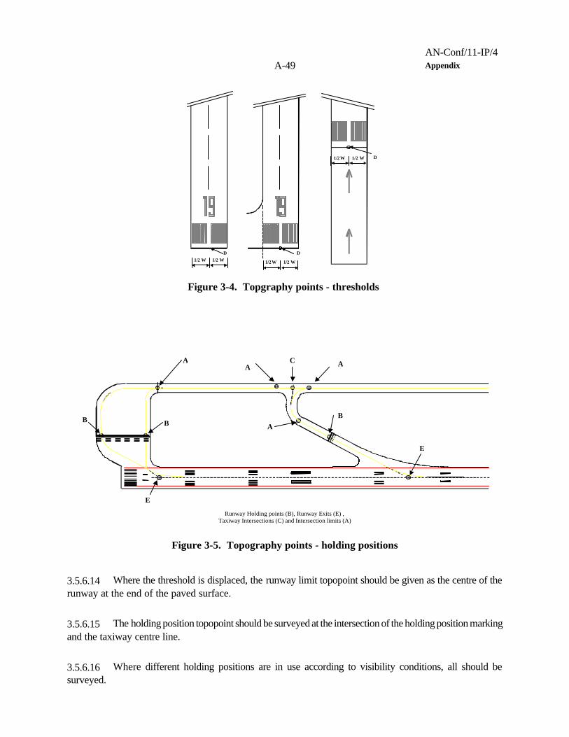
AN-Conf/11-IP/4A-49 Appendix
1/2 W 1/2 WD
1/2 W 1/2 W
D
D1/2 W 1/2 W
Figure 3-4. Topgraphy points - thresholds
A A
B BB
Runway Holding points (B), Runway Exits (E) ,Taxiway Intersections (C) and Intersection limits (A)
A
C
E
E
A
Figure 3-5. Topography points - holding positions
3.5.6.14 Where the threshold is displaced, the runway limit topopoint should be given as the centre of therunway at the end of the paved surface.
3.5.6.15 The holding position topopoint should be surveyed at the intersection of the holding position markingand the taxiway centre line.
3.5.6.16 Where different holding positions are in use according to visibility conditions, all should besurveyed.

AN-Conf/11-IP/4Appendix A-50
AC
A
C
A
A
Figure 3-6. Topgraphy points - taxiway intersections
BLOCK A BLOCK B
d
d/2 d/2
F
Figure 3-7. Topgraphy points - taxiway blocks
3.5.6.17 The stop bar topopoint should be surveyed at the intersection of the stop bar and the taxiwaycentre line.
3.5.6.18 The runway exits topoints should be surveyed at the intersection of the runway centre line and theextension of the nearest straight section of the taxiway centre line (see Figure 3-5).
3.5.6.19 Taxiway intersections should be given by the intersection of taxiways centre lines or of theextension of the nearest straight section of the taxiway centre line (see Figures 3-5 and 3-6).
3.5.6.20 The intersection limits should be given by the intersection of the taxiways centre line and theintersection indication. Where centre line lights are installed, this point should be the same as the beginningof the intersection switchable centre line light blocks (see Figures 3-5 and 3-6).
3.5.6.21 The centre line light-block topopoints should be surveyed on the centre line at the centre of twoconsecutive centre line lights, each of which belonging to a different block.
3.5.6.22 The following points related to parking positions should be surveyed:
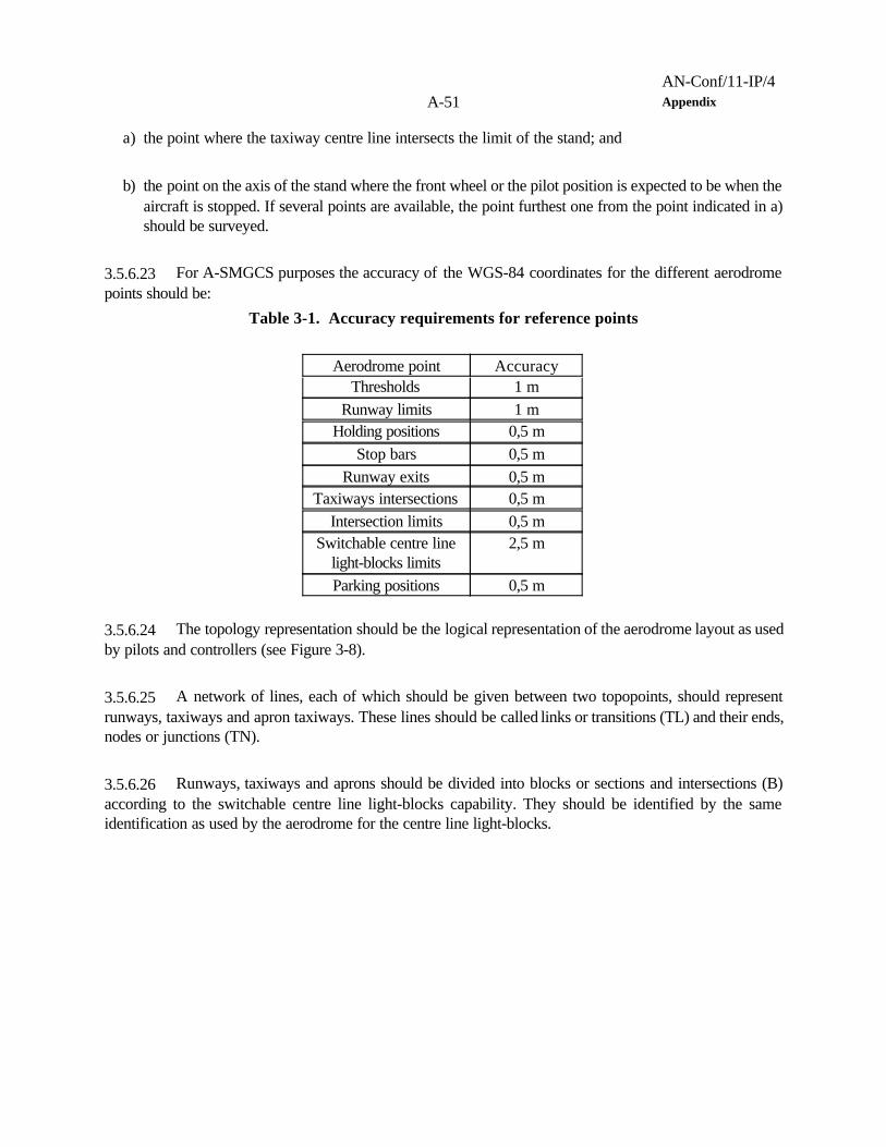
AN-Conf/11-IP/4A-51 Appendix
a) the point where the taxiway centre line intersects the limit of the stand; and
b) the point on the axis of the stand where the front wheel or the pilot position is expected to be when theaircraft is stopped. If several points are available, the point furthest one from the point indicated in a)should be surveyed.
3.5.6.23 For A-SMGCS purposes the accuracy of the WGS-84 coordinates for the different aerodromepoints should be:
Table 3-1. Accuracy requirements for reference points
Aerodrome point AccuracyThresholds 1 m
Runway limits 1 mHolding positions 0,5 m
Stop bars 0,5 mRunway exits 0,5 m
Taxiways intersections 0,5 mIntersection limits 0,5 m
Switchable centre linelight-blocks limits
2,5 m
Parking positions 0,5 m
3.5.6.24 The topology representation should be the logical representation of the aerodrome layout as usedby pilots and controllers (see Figure 3-8).
3.5.6.25 A network of lines, each of which should be given between two topopoints, should representrunways, taxiways and apron taxiways. These lines should be called links or transitions (TL) and their ends,nodes or junctions (TN).
3.5.6.26 Runways, taxiways and aprons should be divided into blocks or sections and intersections (B)according to the switchable centre line light-blocks capability. They should be identified by the sameidentification as used by the aerodrome for the centre line light-blocks.

AN-Conf/11-IP/4Appendix A-52
TN TN
TN
TN
TL TL
TLTL
TL
TL
TN
TN
B
B
B
B
Figure 3-8. Topology points
3.5.7 Reference point
3.5.7.1 A common reference point on aircraft and vehicles should be established for use in A-SMGCS.Any of the following points may be considered:
a) the mid point of the longitudinal axis of the aircraft or vehicle; or
b) the pilot or vehicle driver eye reference position; or
c) the nose wheel of an aircraft or a front wheel of a vehicle; or
d) the nose of the aircraft.
3.5.7.2 For the purpose of providing accurate position, vector and identification information it is desirablethat a single reference point is established for all systems.
3.5.8 Planning
3.5.8.1 It is critical to the efficient and flexible operation of any aerodrome that planning elements can betactically adjusted to meet changing circumstances.
3.5.8.2 Aerodrome operations are vulnerable to many factors which must be taken into account inplanning operations. These factors include weather conditions which may require an adjustment of movement

AN-Conf/11-IP/4A-53 Appendix
rates or landing and take-off directions. Additionally, unserviceable equipment and movement surfaces mayrequire the use of non-routine procedures and routing. Closure of sections of the movement area formaintenance or snow clearance may exceed the allocated expected time.
3.5.8.3 Planning activities will include prediction of aerodrome capacities, gate allocation and groundmovement plans for departures and arrivals. The ground movement planning will calculate different possibleroutes for each aircraft and vehicle taking into account the predicted capacities, gate/slot allocation, theminimum taxi times and delays. These plans will be modified, steadily reducing time horizons down to pre-tactical planning (typically 20 minutes in advance). From that moment, the automated routing function, or theaerodrome controller in the event of an automated routing function not being available, will be tasked to assignan appropriate route for each aircraft and vehicle. The route will be chosen from those proposed by thetactical plan, if available, or from predetermined routes, or, if none of these selections suits the actual needsof the ground movement situation, the route will then be calculated by the system. The route assigned willdepend solely on the ground movement situation that exists at the time when the route is issued.
3.5.9 Recordings
3.5.9.1 To enable an accurate reconstruction of the aerodrome operations, including operator inputs, alldata should be recorded at several locations within the A-SMGCS, including on board aircraft. It is desirablethat any recorded data can be accessed and replayed without the need for specialized software/hardwaretools and knowledge.
3.5.10 System failures
3.5.10.1 The A-SMGCS should have sufficient redundancy, fault tolerance or failure mitigation to enableoperations to continue or be downgraded without affecting the required level of safety. This applies to bothhardware and software failures that cause an interruption or loss of an A-SMGCS function. A back-upprocedure should be provided for any known potential failure.
3.5.10.2 The possibility of an unpredictable and catastrophic failure should be considered. In the event ofsuch a failure, procedures should be provided whereby dependence on the system (which may be the entireA-SMGCS) can be removed.
3.5.11 Start up and restart
3.5.11.1 When switching on any part of the A-SMGCS the equipment should perform an internal systemcheck, including a check of the accuracy of any data, and then be capable of providing operational servicewith minimum intervention by the user.
3.5.12 Aerodrome considerations
3.5.12.1 The siting considerations for A-SMGCS equipment at an aerodrome should not differ from thoseof existing SMGCS. Many requirements for SMGCS are contained in Annex 14, Volume I.

AN-Conf/11-IP/4Appendix A-54
3.5.12.2 An A-SMGCS should be designed such that, wherever possible, changes to the aerodrome willnot require a major re-configuration of an A-SMGCS or its components. A means of system expansion thatupgrades the service and allows the augmentation of extra facilities should be incorporated.
3.5.12.3 The effect on aerodrome operations should be considered in the following areas:
a) the utilization of the movement area in all proposed operational conditions;
b) instrument landing system (ILS) critical and sensitive area protection (if applicable);
c) ATC procedures (especially in low visibility conditions);
d) fire and rescue vehicle operations (especially in low visibility conditions);
e) other ground vehicle operations;
f) existing lighting, markings and signs; and
g) existing structures and their illumination.
3.5.13 ATC considerations
Automation in ATC
3.5.13.1 Few aerodromes have an ideal layout; most have been extended and adapted over time and,therefore, have a varied and complex structure. Few have been constructed with automatic operations takeninto account in the design. This is further complicated by the introduction of new larger aircraft, which willresult in restrictions as to which taxiways certain aircraft can use, introducing a greater need for flexibility.
3.5.13.2 ATC will be responsible for the management and overall operation of the system; however, certainfunctions will be delegated to automated elements of the system.
3.5.13.3 A different division of functions among the control personnel may be necessary and may vary asa result of a possible change in procedures caused by automation.
3.5.13.4 The allocation of functions and/or responsibilities might differ depending on visibility condition, levelof automation and level of implementation of an A-SMGCS. Part or whole of the decision-making processof some functions may necessarily be allocated to the system itself.
3.5.13.5 Automation should be introduced in a modular form and each element should be independent,capable of operating when other elements have become unserviceable. Interfaces should be provided to

AN-Conf/11-IP/4A-55 Appendix
enable controllers to take over the operation of failed elements. These interfaces should also make it possiblefor staff to adjust the functioning of automated elements during normal operation when unplanned events, orinappropriate system function, require amendments to the operation. For example, there may be occasionswhen weather conditions, or equipment failure, require that an automated planning element be adjusted toreduce the start up rate of departures.
3.5.13.6 HMI and automation concepts will require a careful balance in design. While it is recognized thatproliferation of displays and input devices must be avoided, there must also be sufficient duplication to provideback-up services. The search for the correct balance of equipment integrated into the controller workstationwill be one of the major tasks in system design.
3.5.13.7 Training aids should be provided to ensure that staff are able to operate the equipment and be fullytrained in situations where automated functions need to be taken over after failure. This training should notend in the initial phases of introduction, but be continuous to maintain staff competency.
ATC functional requirements
3.5.13.8 For surveillance the controller should be provided with a situation display of the area ofresponsibility of the ATC unit, showing the position and identification of aircraft and vehicles under the controlof that unit. Unauthorized targets which enter the area of responsibility, especially the active runway strips,should also be displayed.
3.5.13.9 When required, the system must allow for manual input by ATC to select alternative routes tosupport a particular operational need.
3.5.13.10 The methods of manually indicating routing instructions should be simple to operate so as not todetract from other primary tasks.
3.5.13.11 ATC must be able to monitor automatically allocated routing instructions and be able to intervenewith re-routing instructions.
3.5.13.12 Where applicable, all control authorities concerned should be provided with methods of guidingaircraft and vehicles on the movement area from their current positions to their intended destinations, includingguidance to any intermediate positions that may be required. Voice communication will remain a primarymethod of providing guidance.
3.5.13.13 A-SMGCS should provide additional control capacity and redundancy to enable ATC tocontinuously control situations which may have progressed beyond the standard operations initially anticipated.
ATC and human machine interface (HMI)
3.5.13.14 Actual traffic flows are not merely a progression from stand to runway and vice versa. Therewill be a great need for flexibility as aircraft may be unable to depart in the established sequence, e.g. when
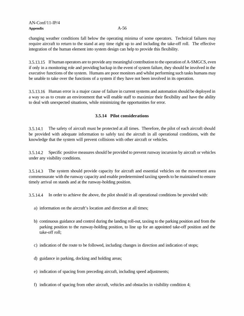
AN-Conf/11-IP/4Appendix A-56
changing weather conditions fall below the operating minima of some operators. Technical failures mayrequire aircraft to return to the stand at any time right up to and including the take-off roll. The effectiveintegration of the human element into system design can help to provide this flexibility.
3.5.13.15 If human operators are to provide any meaningful contribution to the operation of A-SMGCS, evenif only in a monitoring role and providing backup in the event of system failure, they should be involved in theexecutive functions of the system. Humans are poor monitors and whilst performing such tasks humans maybe unable to take over the functions of a system if they have not been involved in its operation.
3.5.13.16 Human error is a major cause of failure in current systems and automation should be deployed ina way so as to create an environment that will enable staff to maximize their flexibility and have the abilityto deal with unexpected situations, while minimizing the opportunities for error.
3.5.14 Pilot considerations
3.5.14.1 The safety of aircraft must be protected at all times. Therefore, the pilot of each aircraft shouldbe provided with adequate information to safely taxi the aircraft in all operational conditions, with theknowledge that the system will prevent collisions with other aircraft or vehicles.
3.5.14.2 Specific positive measures should be provided to prevent runway incursion by aircraft or vehiclesunder any visibility conditions.
3.5.14.3 The system should provide capacity for aircraft and essential vehicles on the movement areacommensurate with the runway capacity and enable predetermined taxiing speeds to be maintained to ensuretimely arrival on stands and at the runway-holding position.
3.5.14.4 In order to achieve the above, the pilot should in all operational conditions be provided with:
a) information on the aircraft’s location and direction at all times;
b) continuous guidance and control during the landing roll-out, taxiing to the parking position and from theparking position to the runway-holding position, to line up for an appointed take-off position and thetake-off roll;
c) indication of the route to be followed, including changes in direction and indication of stops;
d) guidance in parking, docking and holding areas;
e) indication of spacing from preceding aircraft, including speed adjustments;
f) indication of spacing from other aircraft, vehicles and obstacles in visibility condition 4;

AN-Conf/11-IP/4A-57 Appendix
g) indication of the sequencing;
h) information to prevent effects of jet blast or propeller/rotor wash;
i) identification of areas to be avoided;
j) information to prevent collision with other aircraft, vehicles or known obstacles;
k) information on system failures affecting safety;
l) the location of active runways;
m) alert of incursion onto runways and taxiways; and
n) the extent of critical and sensitive areas.
Note.— Most of the foregoing requirements may be satisfied by ground visual aids.
3.5.14.5 Any technological solution to achieving situational awareness should be fully compatible withdevelopments of avionics and other technologies e.g. enhanced vision systems that are being considered forother modes of all weather operations.
3.5.14.6 In using A-SMGCS the operational procedures should be standardized, with no significantvariations, at all aerodromes where all weather operations are conducted.
3.5.14.7 Pilots require precise guidance on touching down on the runway to assist in their deceleration, toidentify and locate the designated rapid exit taxiway, and then follow an unambiguous route on the taxiwayto the assigned stand. When leaving the stand they again require an unambiguous route to the designatedholding position for the assigned runway with additional guidance to line up on the centre line of the runway.
3.5.14.8 The guidance at holding positions and on the apron should be adequate for aircraft to bemanoeuvred in the same close proximity as in unrestricted visibility. The guidance on taxiways should beadequate for the aircraft to follow the taxiway centre line. It should incorporate positive measures to preventerroneous routing and specifically to prevent unauthorized entry (incursion) onto an active runway. Currentsystems of high intensity green centre line lighting are generally adequate for all but the lowest visibility.Systems that can be switched to indicate the designated route, and that use stop bars to control conflictingtraffic from converging routes, are advantageous. The use of additional stop bars at intervals along adesignated route to prevent aircraft from catching up, is likely to restrict capacity and the resulting stop/startprocedures are uneconomical.
3.5.14.9 Supplementary or alternative technical solutions to provide more precise guidance may beoperationally acceptable if they can be economically justified and not result in significantly different visualpresentations to pilots from one aerodrome to another.
AN-Conf/11-IP/4Appendix A-58
3.5.14.10 The system may need to be augmented by equipment in the aircraft or vehicle for operations invisibility condition 4.
3.5.14.11 Pilots require unambiguous and direct conflict-free routings between the runway and the stands.The selection of these routes will be a control authority responsibility. To achieve adequate capacity it maybe necessary to implement unidirectional routes to and from the runway. If data link is used it should satisfythe pilots’ requirements for the receipt and display of routing, situational awareness and conflict detection andresolution.
3.5.14.12 The detection and resolution of conflicts will mainly be a system function. The pilots of the aircraftconcerned and/or the drivers of the vehicles concerned should be advised of all relevant conflicts. Thefollowing situations may require action:
a) active runway ahead;
b) crossing or stationary aircraft/vehicle ahead or close to one side;
c) preceding or diverging, slower moving, aircraft/vehicle;
d) converging aircraft/vehicle; and
e) head-on conflict.
3.5.14.13 At an aerodrome with a high traffic density there is likely to be a number of conflicts arisingsimultaneously. These will be beyond the capability of a single controller to resolve. The system will needto detect and display the situation and the resolution either to the control authority or to the pilot in such termsas:
a) stop or reduce speed;
b) wait until detected visually;
c) re-route via ...;
d) wait until situation resolved; and
e) go around.
3.5.14.14 To maintain capacity, the control authority may deliberately route aircraft or vehicles in closeproximity to each other. In low visibility conditions, visual detection alone may not be adequate. In these
AN-Conf/11-IP/4A-59 Appendix
cases the system should provide adequate spacing between the aircraft/vehicles involved. The pilotrequirements for this are:
a) to be advised of the relative location of proximate aircraft, vehicles or obstructions;
b) to be instructed by the control authority on the action to take; and
c) to be provided with adequate guidance to maintain the required spacing from aircraft or vehicles inclose proximity.
3.5.14.15 In very low visibility conditions, these actions may require additional equipment on the aircraft toenable manoeuvres such as:
a) to follow a preceding aircraft along a taxiway at a predetermined distance; and
b) to pass closely by another aircraft or vehicle.
3.5.15 Vehicle driver considerations
3.5.15.1 A vehicle driver operating on the movement area, with the exception of passive and empty standsand controlled taxiway road crossings, should be provided with radiotelephony capability and adequateinformation to enable the driver to operate the vehicle in all operational conditions, with the knowledge thatthe system will prevent a collision with aircraft and vehicles.
3.5.15.2 Specific positive measures should be provided to prevent incursion by vehicles onto an activerunway under any visibility conditions.
3.5.15.3 Specific positive measures should be provided to prevent incursion onto the movement area byunauthorized vehicles.
3.5.15.4 The system should provide guidance and control for rescue and fire fighting vehicles for them toreach any point on the movement area within the required response time. The system should also providefor operational vehicles carrying out essential duties on the movement area e.g. surface inspections, birdcontrol, de-icing and snow clearance.
3.5.15.5 Authorized vehicles permitted only on apron roads (including controlled and uncontrolledcrossings), passive and empty stands, should not be subject to control by an A-SMGCS.

AN-Conf/11-IP/4Appendix A-60
3.5.15.6 Facilities should be provided for the drivers of all vehicles to be aware of their proximity to themovement area. Additionally, facilities should be provided for the driver of each controlled vehicle to beaware of:
a) the location and direction of the vehicle on the movement area;
b) the assigned route to follow, in particular when that route includes taxiways and/or runways;
c) the relative proximity of any possible conflict on the movement area;
d) the location of any active runway;
e) the extent of runway clear and graded area and strip; and
f) the extent of navigation aid critical and sensitive areas.
3.5.15.7 In most situations, situational awareness could be provided by the use of standard signs, markingsand traffic lights.
3.5.15.8 All vehicle drivers who are required to drive on the movement area should receive formal trainingand certification that they are qualified to drive the types of vehicles or equipment which they will operate.Such training should include all rules and procedures applicable to the aerodrome and knowledge of thoseaspects of an A-SMGCS which applies to vehicle drivers, including use of radiotelephony, when applicable.
3.5.15.9 All vehicle drivers who are required to drive on the movement area need to be tested to ensurethat they meet medical requirements including hearing and colour vision.
3.5.16 Apron management/airport authority considerations
3.5.16.1 At aerodromes operating an A-SMGCS, all vehicles required to move on the movement areashould be equipped to use the system. However, it is unnecessary and uneconomical for vehicles servicingaircraft on the stand only, to be so equipped, because they only move onto the stand once the aircraft hasparked.
3.5.16.2 An “active stand” is included in the movement area whilst a “passive stand” is not. A vacantstand is defined as an "empty stand” and is excluded from the movement area. Therefore, the status ofstands is as follows:
a) active stand — a stand which is occupied by a stationary aircraft with engines operating or on whichan aircraft is moving or which is being approached by an aircraft. When an aircraft is being pushed

AN-Conf/11-IP/4A-61 Appendix
back or is under tow, the stand is also active. When a stand is active all vehicles must remain clear ofthat stand or within designated areas on the stand.
b) passive stand — a stand that is occupied by a stationary aircraft with engines not operating. At thistime, vehicles not under individual control may leave designated roadways and parking areas and movein the proximity of the aircraft to perform servicing tasks.
c) empty stand — a vacant stand not being approached by an aircraft. This stand is available for allocationto incoming aircraft; until then the movement of vehicles on the stand is not restricted.
3.5.16.3 It is not practicable to exercise total control over all traffic on the movement area. On the apron,A-SMGCS applies only to those areas where manoeuvring aircraft may come into conflict with each otheror with vehicles. Therefore, one requirement is to restrict the movement of vehicles on the apron todesignated areas and routes. It is also necessary to keep service vehicles away from an active stand. Thiscan be achieved through painted lines to outline the areas to be left clear when a stand is active. Alternatemeans of protecting an active stand might become available through technology. It is important that any newsolutions retain flexibility to enable A-SMGCS to operate fully during aircraft movements and also permitservice vehicles access to the stand once the aircraft has parked.
3.5.16.4 Authority to change the status of each stand to match its activity will normally be vested in theappropriate control authority. It may be necessary to introduce distinctive coloured light signals at each standto indicate its status.
3.5.16.5 At aerodromes where the movements of aircraft and vehicles are authorized in conditions of verylow visibility conditions (<75 m RVR), conventionally painted demarcation lines in the vicinity of stands mayrequire additional fixed (selectable) lighting to ensure segregation between aircraft and vehicles.
3.5.16.6 When adequate visibility permits the “see and be seen” principle to be applied, it may not benecessary to strictly enforce the declaration and updating of the status of each stand. However, at least ataerodromes where the procedure is implemented in low visibility conditions, it may be considered goodoperating practice to continue to apply these procedure in all visibility conditions.
3.5.16.7 The A-SMGCS functions established for the apron should be compatible with those for all otherareas to ensure the safe and orderly transition of aircraft and vehicles from the apron to other areas.
3.5.17 Automation
3.5.17.1 The use of automation is one of the main differences between SMGCS and A-SMGCS. SMGCSwill evolve to include elements of the A-SMGCS control function, guidance and route assignment.
3.5.17.2 The evolution to an automated system will mean a safer and more efficient operationalenvironment but at the same time, it may mean a more complex environment for human interaction.

AN-Conf/11-IP/4Appendix A-62
3.5.17.3 Any automation should undergo a thorough validation process to ensure that the operationalrequirements are met. The validation process needs to encompass all environmental and failure conditions,including the reversion to manual control.
3.5.18 Human-machine interface (HMI)
3.5.18.1 Although they do not specifically address A-SMGCS, the contents of the ICAO Human FactorsDigests are applicable to the various stages of development, introduction, management, training etc. ofadvanced technologies.
3.5.18.2 At least for the foreseeable future there is a requirement for pilots to continue to operate theiraircraft with no external steering or control facilities during normal taxi operations. The guidance and controlelements of A-SMGCS should, therefore, be optimized for use by the pilots. Additionally, if the flexibility ofhuman operators within A-SMGCS is to be maximized, then human factors issues are equally important.
3.5.18.3 The basic limitation and a primary design factor is the ability of pilots, vehicle drivers and systemoperators to interpret the guidance and control elements of A-SMGCS and to carry out their respectiveresponsibilities.
3.5.18.4 The flight deck tasks are composed of a sequence of visual, audio and tactile operations. Careshould be taken in the balance of these actions to ensure that there is not an overload in any one area. Theneed for the crew to retain control of the aircraft has already been stated. The difficulty of navigating in lowvisibility conditions will place a high workload in the visual area, with a high degree of concentration required.Care should be taken that no one factor is used to the limit.
3.5.18.5 The factors mentioned in 3.5.18.4 apply equally to the tasks of the staff operating the system.Although direct observation is restricted during times of low visibility, this does not remove the need for thistask. It is envisaged that A-SMGCS will not only be in operation during times of low visibility conditions, butalso in all weather conditions to maximize the capacity of the aerodrome. At the very least there will besituations, during transition to and from low visibility conditions, when visual observations will be possible andwill be a necessary part of the operation.
3.5.18.6 ATC should always have the capability to observe the aerodrome activity. Speech and audio inputenables the operator to carry out other tasks, including observation, whilst keyboard and message displaysrequire a higher level of visual concentration and tactile actions. Advanced technology will require the useof such interfaces, but their use should be balanced so as not to detract from other essential tasks.
3.5.18.7 It is recommended that users and operators of systems should be involved in the design of relevantsystem elements at an early stage, so that operational functions can be optimized for their use. This will becritical to the efficiency and effectiveness of the system.
3.5.19 Interfaces

AN-Conf/11-IP/4A-63 Appendix
3.5.19.1 The aerodrome operation is an integral part of the overall ATM system. Aerodrome capacityshould be matched to the ability of the surrounding airspace system to handle the generated air traffic. Thereshould be a seamless exchange of information between A-SMGCS and ATM systems.
3.5.19.2 There are three prime users of A-SMGCS: controllers, pilots and vehicle drivers. Each of themneeds to be able to interface with the system. Additionally, the system will need to interface with othersystems.
3.5.19.3 System interface with pilots and vehicle drivers should, in principle, be based on visual aids andradiotelephony with the possibility in the future of augmentation with on-board displays and air-ground datalinks.
3.5.19.4 Information required by the A-SMGCS from other systems include, but is not restricted to, thefollowing:
a) runway allocation;
b) arrival/departure sequence;
c) aircraft type;
d) aircraft identification;
e) estimated time of arrival (ETA) and estimated time of departure (ETD);
f) stand allocation (if done by a different system);
g) meteorological data;
h) emergency situations;
i) priorities;
j) slot allocation; and
k) infrastructure limits (e.g. maintenance purposes, aircraft de-icing etc.).
AN-Conf/11-IP/4Appendix A-64
3.5.19.5 Information required to be passed by an A-SMGCS to other systems includes, but is not restrictedto, the following:
a) actual time of arrival/departure;
b) data to enable actual aerodrome capacity to be monitored;
c) aerodrome equipment, services and procedures available;
d) aeronautical ground light status;
e) surface movement emergency situations;
f) real time of stand allocation;
g) estimated early stand arrival; and
h) aborted take-off situations;
3.5.19.6 The need to automatically register all communication data affecting operations should be studied.
3.6 SYSTEM REQUIREMENTS
3.6.1 Accuracy
3.6.1.1 The term accuracy generally describes the degree of conformance between a true position andspeed and its estimated position and speed.
3.6.1.2 The accuracy requirement of an A-SMGCS will depend on several factors including:
a) the category of the aerodrome;
b) the functional complexity of the A-SMGCS design; and
c) the level of dependency on automation.
3.6.1.3 The true value of the accuracy requirement of an A-SMGCS should be determined by a safetyassessment carried out for the specific aerodrome.
AN-Conf/11-IP/4A-65 Appendix
3.6.2 Integrity
3.6.2.1 Integrity relates to the trust which can be placed in the correctness of the information providedby an A-SMGCS. Integrity includes the ability of an A-SMGCS to provide timely and valid alerts to the userswhen an A-SMGCS should not be used.
3.6.2.2 In the event of any failure, an appropriate alert including the operational significance of the failureshould be provided.
3.6.2.3 A safety assessment should be carried out on the level of integrity and should be directly relatedto the TLS. Other integrity requirements include:
a) determination of the integrity risk — the probability of an undetected failure, event or occurrence withina given time interval;
b) error identification — an error detection process should be deployed that will maintain the required levelof integrity;
c) error classification — each detected error should be analysed and a corrective or error processingmethod should be initiated within a specified time;
d) error handling — specifies the number of attempts or retries allowed within a given time period tocomplete an error free function, transaction or process before a failure is declared;
e) data integrity and validation — latent data within an A-SMGCS should be continuously checked for itsintegrity. This includes data that have a specified life cycle and that are contained within databases;and
f) information errors — the prevention of the propagation of hazardous or misleading information.
3.6.2.4 Access to an A-SMGCS and the ability to perform certain functions (such as systemconfiguration) should be restricted to authorized personnel only. The service providers should ensure that anA-SMGCS integrity level addresses the hazard posed by unlawful, accidental or other unauthorized access.Procedures should be in place for the detection of access violation and the consequence of such action.
3.6.3 Availability
3.6.3.1 In case of a system failure that has a long-term effect on the availability, appropriate action (e.g.promulgation of NOTAM) should be taken to notify all users of the system status.
AN-Conf/11-IP/4Appendix A-66
3.6.3.2 An A-SMGCS is an integral part of the overall aerodrome operations and a significant part of theATM system. The required level of availability should therefore be equal to or better than the availability ofother integral systems within the aerodrome or the ATM system.
3.6.3.3 During essential maintenance, the availability of all the functions within an A-SMGCS should notbe affected at the same time. Fault tolerance and maintainability should be maximized so that an A-SMGCSwith reduced capability would still be able to offer a safe and efficient level of service.
3.6.3.4 When an A-SMGCS is designed such that one or more of its functionalities depend on on-boardequipment, the system should have the ability to safely handle aircraft with unserviceable equipment.
3.6.3.5 The operational needs of an individual aerodrome include:
a) weather conditions under which take-off and landing can be performed;
b) necessity for improved surveillance, routing, guidance or control capabilities that are not achievable withconventional SMGCS;
c) any safety aspects under any weather condition;
d) consideration of interrelation between functions; and
e) consideration of interrelation between functions on destination and alternate.
3.6.4 Continuity
3.6.4.1 Continuity is the ability of an A-SMGCS to perform its required function without non-scheduledinterruption during the intended operation.
3.6.4.2 In accordance with the system performance and safety requirements, an A-SMGCS should bedesigned such that the probability of an interruption during the performance of a critical function or servicewill not exceed the acceptable limit.
3.6.5 Reliability
3.6.5.1 There is a very close link between the required integrity of an A-SMGCS and the reliability of thesystem. In order to get a highly reliable system with high integrity it is sometimes necessary to duplicate oreven triple components, thereby increasing the cost and complexity. Also, at some point there is usually afailure transfer mechanism which, being a common mode failure point, could be detrimental to the reliability.Often a compromise is reached depending on the criticality of the component and its functionality.

AN-Conf/11-IP/4A-67 Appendix
3.6.5.2 Important reliability aspects to consider are:
a) the criticality of a system component with regard to the functionality;
b) how a failure is detected;
c) that all critical failures will be detected;
d) how a failure impacts upon the system functionality;
e) how a failure is contained or handled; and
f) how the user is notified of the failure.
____________________

AN-Conf/11-IP/4Appendix A-68
Chapter 4
PERFORMANCE REQUIREMENTS
4.1 SYSTEM REQUIREMENTS
4.1.1 General
4.1.1.1 Prior to the implementation of an A-SMGCS, the system performance and functional requirementsshould be demonstrated in order to assure that the design specifications or requirements have been met.
Safety
4.1.2 The A-SMGCS target level of safety (TLS) should be 1 x 10⁻⁸ collisions per operation involving aircrafton the ground.
4.1.3 The function risk has been estimated as:
a) guidance: 3.0 x 10⁻⁹ per operation;
b) surveillance: 3.0 x 10⁻⁹ per operation;
c) control: 3.0 x 10⁻⁹ per operation; and
d) routing: 1.0 x 10⁻⁹ per operation.
Coverage
4.1.4 The A-SMGCS should cover at least the movement area of the aerodrome and aircraft on approachto each runway at such a distance that inbound aircraft can be integrated into the A-SMGCS operations.
Capacity
4.1.5 The A-SMGCS should be able to handle all aircraft and vehicles that are on the movement area at anytime.

AN-Conf/11-IP/4A-69 Appendix
4.1.6 The determination of the maximum number of aircraft on the manoeuvring area should be based onthe assumed peak traffic at the aerodrome. The A-SMGCS capacity should be sufficient to cater forincreased capacity and be reviewed on a regular basis to ensure that it is sufficient.
Speeds
4.1.7 The A-SMGCS should accommodate with sufficient accuracy all aircraft/vehicle speeds that will beused within the coverage area.
4.1.8 The A-SMGCS should be able to accommodate the following speeds determined to within ± 2 km/h(1 kt):
a) 0 to 93 km/h (50 kt) for aircraft on straight taxiways;
b) 0 to 36 km/h (20 kt) for aircraft on taxiway curves;
c) 0 to 150 km/h (80 kt) for aircraft on runway exits;
d) 0 to 460 km/h (250 kt) for aircraft on final approach, missed approach and runways;
e) 0 to 150 km/h (80 kt) for vehicles on the movement area; and
f) 0 to 20 km/h (10 kt) for aircraft and vehicles on stands and stand taxi-lanes.
4.1.9 For all aircraft/vehicles moving at speeds within the ranges described above, the A-SMGCS shouldbe able to perform the surveillance and guidance functions in accordance with, and without degradation of,the control and routing functions. This is particularly relevant to the switching of visual aids and human-relatedfunctions.
4.1.9 The A-SMGCS should determine the direction of movement in terms of magnetic heading of eachparticipating aircraft and vehicle to within ± 1E.
4.2 SURVEILLANCE REQUIREMENTS
Note.— It is expected that more than one type of surveillance sensor will be needed to meet therequirements.

AN-Conf/11-IP/4Appendix A-70
4.2.1 A reference point on aircraft and vehicles is required to enable the A-SMGCS to determine theirpositions. Although this requirement applies to the surveillance function, it is used predominantly in the controland guidance functions.
4.2.2 The actual position of an aircraft, vehicle or obstacle on the surface should be determined within aradius of 7.5 m.
4.2.3 Where airborne traffic participates in the A-SMGCS, the level of an aircraft when airborne should bedetermined to within ±10 m.
4.2.4 The surveillance function should be capable of detecting aircraft, vehicles and obstacles.
4.2.5 Methods should be employed to reduce adverse effects such as signal reflections and shadowing toa minimum.
4.2.6 The position and identification data of aircraft and vehicles should be updated at least once per second.
4.2.7 The latency and validation of surveillance position data for aircraft and vehicles should not exceed 1second.
4.2.8 The latency and validation of identification data for aircraft and vehicles should not exceed 3 seconds.
4.3 ROUTING REQUIREMENTS
4.3.1 The requirements listed in Table 4-1 should be used in the design of the routing function.
Table 4-1. Routing maximum failure rate requirements
VisibilityCondition
Requirement(Failures per hour)
1 1.5E-032 1.5E-043 3.0E-064 1.5E-06
4.3.2 The time taken to process an initial route should not exceed 10 seconds. Reprocessing to account fortactical changes once the aircraft or vehicle is in motion should not exceed 1 second.

AN-Conf/11-IP/4A-71 Appendix
4.3.3 In the processing of optimized routes, the length of taxi distances should be computed to a resolutionbetter than 10 m, and timing to a resolution better than 1 second.
4.4 GUIDANCE REQUIREMENTS
4.4.1 The overall response time of initiation of the guidance to verification that the correct route orinformation has been provided, should not exceed 2 seconds.
4.4.2.2 The reversion time should be maximum 0.5 seconds.
4.5 CONTROL REQUIREMENTS
4.5.1 The probability of detection of an alert situation (PDA) should be greater than 99.9 per cent. Theprobability of false alert (PFA) should be less than 103.
4.5.2 The response time of any control function should be less than 0.5s.
4.5.3 Longitudinal spacing (See Figure 3-2) should be based on the following typical numerical values:
a) Va = 55 km/h (30 kt);
b) Vb = 55 km/h (30 kt);
c) Aa = 1-2 m/s2 (depending on aircraft weight, friction coefficient etc.);
d) Ab= 1-2 m/s2 (depending on aircraft weight, friction coefficient etc.);
e) Pir = 1 sec;
f) Cor = 1 sec;
g) Syr = 2 sec;
h) Sar = 1 sec.
4.5.4 On the basis of calculations using the above data, it can be concluded that:

AN-Conf/11-IP/4Appendix A-72
a) a design taxi speed of 55 km/h (30 kt) is practicable;
b) a longitudinal spacing (St) of approximately 200 m, with aircraft taxiing in trail, will be required toachieve the minima specified below; and
c) a minimum spacing when the aircraft have stopped (Ss + Lj) of approximately 60 - 15 m can beprovided by the system, with the lower figure applying to holding positions.
____________________
AN-Conf/11-IP/4A-73 Appendix
Chapter 5
IMPLEMENTATION ISSUES
5.1 INTRODUCTION
5.1.1 The following paragraphs outline some of the activities that might be done prior to and during thedesign and implementation of an A-SMGCS, particularly with respect to the assurance that the A-SMGCSwill meet the requirements of the aerodrome and provide a solution to the safety and/or capacity problemsat the aerodrome.
5.2 CAPACITY ASSESSMENT
5.2.1 General
5.2.1.1 It should be ensured that the system will always have sufficient capacity to accommodate theaerodrome traffic demand maintaining a predetermined capacity margin, i.e. to ensure a correct capacitydemand balance (CDB).
5.2.1.2 The CDB should also be used to alert when demand drops below capacity in such a way thatmeasures could be taken to save resources.
5.2.2 Capacity management
5.2.2.1 The following different capacities should be taken into account:
a) theoretical capacity — calculated for existing facilities (layouts, systems, etc.), it will comprise:
1) apron capacity — maximum number of aircraft (with indication of types) that can be parked;
2) taxiway capacity — maximum number of aircraft that can be operating on the taxiways at thesame time;
3) runway capacity — maximum number of runway movements per hour; and
4) approach capacity — maximum number of transfers between the aerodrome controller andapproach controller.
AN-Conf/11-IP/4Appendix A-74
Each of the above-mentioned capacities should be calculated using both design and operational values andreferred to predetermined units of time.
b) downgraded capacity — aerodrome capacity derived from the theoretical capacity reduced due tofacility limitations (failures, maintenance, weather conditions, local regulations etc.);
1) different values should be calculated taking into account the following;
i) long term — activities related to stored flight plan arrivals and departures;
ii) short term — activities related to en-route, inbound or pre-departure aircraft; and
iii) real time — activities related to actual aircraft movements on and in the vicinity of theaerodrome.
5.2.3 Demand management
5.2.3.1 As for capacity, the demand should be allocated to the different aerodrome areas (apron, taxiwayand runway), taking into consideration arriving, departing and parked aircraft.
5.2.3.2 To obtain the different demand values throughout the complete time horizon, the system should takein account not only the flight plans and aircrew or airline requests, but also temporary constraints as well asunusual traffic peaks and unexpected arrivals due to restrictions at other aerodromes.
5.2.4 Mechanisms for balancing demand and capacity
5.2.4.1 Problems will arise whenever the ratio between capacity and demand gets closer to one.
5.2.4.2 The value of the predetermined margin, which will reflect the uncertainties in assessments of demandand capacity, must be given to the system in the implementation phase and afterwards modified to reflectexperience gained.
5.2.4.3 The time available for anticipating problems is a key factor in determining which actions should betaken. The further in advance predictions can be made, the wider the range of options which can be applied.
5.2.4.4 Depending on the time horizons, from months in advance to the actual situation, different actions canbe taken to either modify the demand or the capacity.

AN-Conf/11-IP/4A-75 Appendix
5.2.4.5 The following present some of the possible actions:
a) for the long term:
1) increase capacity of the critical (bottleneck) resource; and/or
2) reduce demand for that resource by modification of stored flight plans (only after confirmationthat there is no other solution);
b) for the short term:
1) modification of flight plans of en-route, inbound or departing aircraft;
2) diversions to other aerodromes of arriving aircraft (only after confirmation that there is no othersolution).
c) for real time:
1) re-allocation of slots for departing aircraft.
5.3 COST/BENEFIT ASSESSMENT
5.3.1 General
5.3.1.1 The use of cost/benefit analyses help decision makers to determine the best alternative to systemdevelopment and deployment of equipment and services supporting A-SMGCS. While the complexity ofaerodrome surface movement increases as visibility decreases, the benefits may accrue in increments notdirectly related to visibility. For example, if the sharing of information on take-off delays can produceefficiencies in air traffic management, this benefit could be realized in any visibility condition. Thoseaerodromes developing A-SMGCS capabilities should consider visibility conditions in their cost and benefitanalyses, but not as the only factor.
5.3.1.2 Risk analyses can measure the improvements expected through changes in procedures or additionof technology. Risk analyses produce a probability of an event (i.e. runway incursion, surface collision, etc.).An improvement proposed on the aerodrome should show a reduction in risk.
5.3.1.3 Benefits, expressed in terms of cost avoidance, aircraft loss, loss of life, disruption to aerodromeservices, cost of investigation, etc. can be used to turn risk reduction into a quantitative value. However,

AN-Conf/11-IP/4Appendix A-76
because surface accidents are rare, these cost avoidance savings may be “soft” savings, meaning that theymay or may not be realized.
5.3.1.4 Quantifiable benefits tied to efficiency can be determined and improvements assessed against thesebenefits. Savings expected can be measured after the procedural change or addition of technology. Theaerodrome users can validate expected savings in terms of reduced delay, taxi in and taxi out time, aircraftturn around time at the gate, improved aircraft servicing, improved aerodrome capacity (in terms of throughputexpressed as operations per hour), or reduced operating costs. Efficiency benefits accrue with everyoperation, while safety benefits may remain unseen. Regarding safety benefits, there are no guarantees thatan accident will not occur, even though risk is reduced.
5.3.1.5 The conduct of cost/benefit assessments will vary with standard economic practices of States andaerodromes. The described assessment should provide the basis for modifying the approach to fit the needs.Those doing cost/benefit analyses can vary from the assessment methodology proposed, provided the groundrules, assumptions, and data are provided. This will allow aerodrome users and others to apply their ownmethodology to determine benefit for their operations.
5.3.2 Cost/benefit guidelines
5.3.2.1 The primary benefits for operators are related to improved operating efficiencies. Aerodromes andair traffic control benefits include both safety and efficiency. Safety and efficiency benefits should besegregated in the analyses to facilitate decision making.
5.3.2.2 Define and provide measures of changes in capacity to the maximum extent possible. This will allowthe aerodrome user to determine whether the capacity gain warrants improved aircraft equipage.
5.3.2.3 Consider benefits which may occur due to avoidance of costs associated with diversions andcancellations, including cost of getting passengers to their final destination.
5.3.2.4 Identify hourly costs of taxi time, which may be different from hourly block time costs traditionallyused in cost/benefit analyses. The taxi time cost is more representative of surface operations cost.
5.3.2.5 Consider benefits which may occur due to improved command and control, not just air trafficmanagement improvements. The sharing of surveillance information can provide command and controlbenefits for the aerodrome operator and service providers on the aerodrome.
5.3.2.6 Use aerodrome traffic growth forecasts or national growth forecasts to estimate future demand.
5.3.2.7 Use historical weather data for projected operating hours in visibility conditions 1 through 4.

AN-Conf/11-IP/4A-77 Appendix
5.3.2.8 Wherever possible, incremental analyses should be undertaken, so that only the additional benefitsof a new initiative, net of any previous initiatives, can be determined. Modular addition of capabilities toimprove services is the basis of any A-SMGCS implementation. Cost/benefit analyses should be equallymodular to capture incremental improvements.
5.3.2.9 Use current and projected costs and determine overall cost using life-cycle costing. A life-cycle costestimate includes the cost of research, engineering and development, acquisition, operation, decommissioning,and disposal costs. In the event that an alternative or project requires user equipage, these costs must beincluded. Both non-recurring and recurring costs should be considered. The source of the cost data shouldbe explained for each major cost element.
5.3.2.10 The method of computing cost and benefit values should be explained, including discounting,proportional distribution of benefits, yearly distribution of costs and benefits, and timing for realizing benefitsor incurring costs.
5.3.2.11 A module in an A-SMGCS may have value for operations beyond surface movement. Therefore,analyses should define how benefit and cost segments are attributed to surface applications.
5.3.2.12 Previously procured systems were justified based on their own merits. The cost of sustainingan operational surface movement radar should not be charged against A-SMGCS unless a new radar wouldbe required with improved performance. In this case, a replacement system should be considered as one ofthe modules for cost/benefit analyses.
5.3.2.13 Non-personnel related cost avoidance may include maintenance savings, reducedtelecommunications costs, leases, rents, utilities, and the deferral or elimination of the need to make a capitalinvestment.
5.3.2.14 Secondary user benefits should be identified. An A-SMGCS produces information as a product.Whether it be improved surface surveillance, scheduling information, gate allocations etc. this information hasvalue to service providers beyond air traffic control, the aerodrome users, and the aerodrome operator.
5.3.2.15 System performance trade-offs should be considered in balancing cost and benefit. There maybe opportunities to meet the goals of A-SMGCS through trade-offs in technology and procedures. A goodcost/benefit analysis will consider each alternative and the modules defined within the envisioned system.These trade-offs should be clearly defined so that others reviewing the analysis and the decision makers canconsider these trade-offs.
5.3.3 Identifying benefits
5.3.3.1 Benefits are improvements realized over the existing baseline capability. Starting with the operationalrequirements given in this document, add local, site-specific user and aerodrome requirements. Compare theexisting baseline operating capabilities to those proposed in the new operational requirements for A-SMGCS.

AN-Conf/11-IP/4Appendix A-78
Define who gets the benefits. This allocation of benefits will help in quantifying both benefit and cost. Theallocation will also help in developing the assumptions which will be used in the analyses.
5.3.3.2 Table 5-1 provides a representative breakdown of benefits. This table should be modified, asnecessary, for each particular aerodrome.
5.3.3.3 Table 5-2 provides a listing of potential users of information provided by A-SMGCS. The table wasdeveloped to identify primary and secondary users of information. Some aerodrome authorities may restrictthe access to information.
5.3.4 Identifying cost
5.3.4.1 Cost should be defined as life-cycle cost. In the past, air traffic control systems have been developedwith an expected life-cycle of 20 years This trend is changing with the introduction of improved, cost-effective automation and reliance on commercial products. An air traffic control hardware life of 5 to 10years is becoming more common. Commercial airlines expect a 20 year life cycle for equipment installed bythe aircraft manufacturer. For airline-installed equipment, the life cycle is in the order of 5 to 7 years foravionics while the cost recovery for avionics is typically 3 to 5 years; however, in periods of slow airlinegrowth, cost recovery in 12 to 18 months is expected.
5.3.4.2 Table 5-3 contains the user cost breakdown. Potential sources of project cost are provided in Table 5-4.
5.3.4.3 These cost tables show examples of potential sources of cost. Each A-SMGCS may producedifferent cost sources. The primary objective is to develop a list of applicable cost sources early in theanalyses. As in the benefits analyses, it is important to solicit participation from all affected service providersand users early in the process.
5.3.4.4 Another metric for economic justification is net present value, the discounted value of expected netbenefits (i.e. benefits minus costs). In order to compute net present value, benefit and cost streams arediscounted by a specified rate. This discount rate may vary with each State. The rate also differs within theuser community.
5.3.5 Recommended outline for cost-benefit analysis and report
5.3.5.1 A brief summary of objectives, costs, alternatives investigated, methodology, and benefits and costsassessed.
5.3.5.2. Discussion of any historical data that helps to define the shortfall in capabilities and applicationof any previous cost-benefit studies which will be used.

AN-Conf/11-IP/4A-79 Appendix
5.3.5.3 A description of the current baseline, shortfalls in the existing system, and proposed solutions toovercoming these shortfalls.
5.3.5.4 Technical and procedural alternatives which can fulfil mission needs, the characteristics of eachalternative, and whether each alternative meets all or a portion of the mission need.
5.3.5.5 A description of each ground rule and assumption used in identifying cost and benefits, includingfactors used to discount values.
5.3.5.6 A description of methods used to estimate benefits and costs, equations used, and data sourcesreferenced.
5.3.5.7 Life-cycle costs should be assessed consistent with the ground rules and assumptions used.Parametric, vendor quotes, and analogy methods should be used to estimate life-cycle costs and extrapolatecosts over the life-cycle.
5.3.5.8 A description of benefits identified, presented in a modular fashion so that incremental benefits canbe understood.
5.3.5.9 A comparison of benefits and costs for each alternative with a ranking in terms of most benefit forleast cost.
5.3.5.10 Levels of confidence of benefit and cost information as determined by probabilistic analysis. Theeffects of varying the values of key assumptions should also be tested.

AN-Conf/11-IP/4Appendix A-80
Table 5-1. Benefits breakdownService provider benefitsATM service providers *Controller productivity
*Maintenance productivity*Leased communications savings*Rent, utility, other savings*Liability cost savings*Future capital cost avoidance
Other air navigation service providers *Productivity *Maintenance productivity*Leased communications savings*Rent, utility, other savings*Liability cost savings*Future capital cost avoidance*Reduced service cost to user
Aerodrome service providers *Increased capacity (operations per hour)*Operations productivity*Maintenance productivity*Improved passenger handling*Improved rescue response*Reduced time when runway(s) unusable
User benefitsDelay savings Air carrier *Aircraft operating cost savings
*Diversion avoidance*Reduced flight cancels
Commuter and air taxi *Aircraft operating cost savings*Diversion avoidance*Reduced flight cancels
General aviation *Aircraft operating cost savingsMilitary aviation *Aircraft operating cost savings
*Improved all weather capabilitySafety *Fatalities avoided
*Injuries avoided
*Aircraft losses avoided
*Aircraft damage avoided
*Ground vehicle damages avoidedEfficiency Air carrier *Aircraft operating cost savings
*Aircraft turn time reduced
*Personnel savings
*Maintenance savings
*Avoided capital investment costCommuter and air taxi *Aircraft operating cost savings
*Aircraft turn time reduced
*Personnel savings
*Training savings
*Maintenance savings
*Avoided capital investment costGeneral aviation *Aircraft operating cost savings
*Aircraft turn time reducedMilitary *Aircraft operating cost savings
*Aircraft turn time reduced
*Personnel savings
*Maintenance savings
*Avoided capital investment costInformation user efficiencies *Improvements in command and control
*Improved level of service
*Personnel savings
*Training savings
*Maintenance savings

AN-Conf/11-IP/4A-81 Appendix
*Aircraft turn time reduced
*Passenger/cargo throughput improvements

AN-Conf/11-IP/4Appendix A-82
Table 5-2. Information users
User Terminal surveillance Surface surveillance Flight plan data Arrival data listAir traffic control x x xApron management x x xOperations (airline) x x x xOperations (aerodrome) x x x xMaintenance aerodrome x x xSnow removal team x x x xRescue and fire fighting xNoise monitoring xFinance (landing fees) xFlight information display systems x xGround transportation x xBaggage handling x xFuelling x xCatering x xCustoms and immigration x xLodging facilities x x
Note.— 1 Terminal surveillance allows position and time to be reported for aircraft in the terminal area.
Note.— 2. Surface surveillance reports position of aircraft and vehicles in the manoeuvring areas. If surveillance coverage is extended to theramp area, then surface surveillance will have increased value for control.
Note.— 3. Flight plan data provides departure information with gate/stand identified.
Note.— 4. Arrival data list contains the expected landing time and gate/stand arrival time, with gate identified.
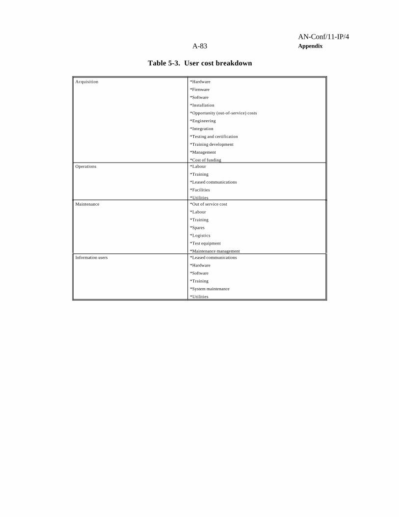
AN-Conf/11-IP/4A-83 Appendix
Table 5-3. User cost breakdown
Acquisition *Hardware
*Firmware
*Software
*Installation
*Opportunity (out-of-service) costs
*Engineering
*Integration
*Testing and certification
*Training development
*Management
*Cost of fundingOperations *Labour
*Training
*Leased communications
*Facilities
*UtilitiesMaintenance *Out of service cost
*Labour
*Training
*Spares
*Logistics
*Test equipment
*Maintenance managementInformation users *Leased communications
*Hardware
*Software
*Training
*System maintenance
*Utilities

AN-Conf/11-IP/4Appendix A-84
Table 5-4. Cost breakdownProject management *Management efforts
*Financial management
*Planning and scheduling
*Contract management
*Data managementSystems engineering *Engineering management
*Interface management
*Configuration management
*Quality assurance
*Production management
*Transition management
*Technical monitoring
*Operational requirements
*System designPre-production *Proof of concept
*Prototype development
*Deployment costsPrime mission equipment *Hardware
*Firmware
*Software
*Integration
*Production/assemblyTesting *Test programme
*Developmental testing and evaluation
*Operational test and evaluationData *Technical manuals
*Engineering data
*Data depository
*Other documentationTraining *Training requirements analysis
*Training manuals
*Management
*Course development
*Course deliveryIntegrated logistics *Logistics management
*Support equipment
*Spares
*Warehousing
*Facility requirementsSite activation *Site procurement
*Site survey
*Environmental assessments
*Site preparation
*Site installation and checkoutOperational support *Contractor maintenance
*Direct work maintenance
*Supply support
*Support equipment
*Training and training support
*Leased communications
*Facilities
*Utilities
*Periodic inspection and/or certificationDisposal *Disposal management
*Dismantle/decommission
*Demolition
*Environmental audits
*Hazardous waste management
*Facility construction or conversion

AN-Conf/11-IP/4A-85 Appendix
*Site restoration
*Salvage value recovery
5.4 GENERIC METHODOLOGY FOR ASSESSING CAPABILITIES
OF SPECIFIC SYSTEMS TO MEET A-SMGCS REQUIREMENTS
5.4.1 Introduction
5.4.1.1 The assessment of specific technologies should preferably use a standardized methodology so as tohave a baseline reference for each technology that will be assessed. The assessment is an iterative process,which should take place in close cooperation between those involved i.e. authorities, service providers,operators and manufacturers.
5.4.1.2 The feasibility of application of various technologies and systems should be proven by a feasibilityassessment, which determines whether a selected technology meet the requirements. This feasibilityassessment could comprise various techniques, such as a theoretical analysis, simulation, or simply by datacollection.
5.4.1.3 If the assessment takes place according to a standardized methodology, the documented results ofthe assessment could serve as an element of a certification process and as evidence of the performance ofthe system or part thereof up to the operational requirement.
5.4.2 Generic technology assessment methodology
5.4.2.1 The information flow in the assessment process is illustrated in the flow diagram (Figure 5-6).Important first steps include the definition of the technology to be assessed, the specific architecture of thistechnology, and the role (e.g., the guidance function) that this technology is proposed to fulfil in the A-SMGCS. It is possible that this architecture may change during the assessment process as difficulties insatisfying certain requirements become apparent. When such a change occurs, it is important to documentthe revised architecture completely and restart the assessment process from the beginning.
5.4.2.2 In documenting the technology, the architecture, and the role in A-SMGCS to be assessed, a tabularformat may be useful to support the text.
5.4.3 Generic assessment parameters
5.4.3.1 The operational and performance requirements for the A-SMGCS should be dissolved intoquantitative performance parameters and qualitative design guidelines. Where available, a metric has beenassociated with each performance parameter. The resulting generic matrix is intended to provide the basisfor assessing a technology, which is proposed for application in the A-SMGCS.

AN-Conf/11-IP/4Appendix A-86
OperationalRequirements
(OR)
Begin
DefineTechnology
andArchitecture
DefineRole of Technology
inA-SMGCS
SelectFunction
andOperational Requirement
IdentifyParameters
IdentifyNumerical Value
Required
DeterminePerformance
ofTechnology/Architecture
Is the PerformanceOK?
AcceptSystem for this
Functionand OR
All Functionsand OR
Assessed?
End
RejectSystem for this
Functionand OR
PerformanceRequirements
Feasability Assessment:
Theoretical Analysis:- Failure Mode Analysis- Hazard AnalysisSimulation:- Monte Carlo Technique- Real Time- Fast TimeData Collection:- Actual Operation Simulated
YES
NO
NO
YES
Figure 9. Flow diagram generic technology assessment methodology

AN-Conf/11-IP/4A-87 Appendix
5.5 SAFETY ASSESSMENT
5.5.1 Introduction
5.5.1.1 Before an A-SMGCS is declared operational, a safety assessment should be made to understand thesafety impact caused by the application of the system and also the safety impact in case of failure of elementsof the system. The safety assessment should be supported by relevant documentation, which should be ina format that enables easy updating after system modification. The documentation should clearly indicateagainst which objectives the assessment took place and if these safety objectives were fully met.
5.5.1.2 The safety assessment is not only meant to convince the authority of the safety of the system but alsoto clearly indicate aspects like training and controls upon which the safety depends so that the required safetylevel can be maintained.
5.5.2 System description
5.5.2.1 In order to perform a safety assessment a description of the total system is required. This descriptionstarts with a description of the system to be assessed. This should include:
a) the intended functions of the system including its modes of operation;
b) the system performance parameters and their allowable limits (e.g. what constitutes a failure);
c) the functional and physical boundaries of the system and its components;
d) the environmental conditions which the system needs to withstand;
e) the interfaces with other systems and with human operators (controllers, pilots and vehicle drivers);and
f) functional block diagrams of the system and its interfaces.
5.5.3 Hazard analysis
5.5.3.1 The hazard analysis should indicate what constitutes a failure condition of the system. The hazardanalysis should focus on the functions and vulnerabilities of the system and include:
a) the consequences of a failure of an A-SMGCS or a part thereof to function within its specifiedperformance limits;
b) the consequences of other possible malfunctions of the system and their effects on other systems;

AN-Conf/11-IP/4Appendix A-88
c) the consequences to an A-SMGCS of failures in other systems;
d) the identification of possible common-mode or cascade failures (e.g. a failure of a guidance systemthat causes several aircraft to loose their guidance); and
e) the identification of possible sources for errors by human operators.
5.5.3.2 The result of the hazard analysis may well be an indication for the need of a system (or part thereof)re-design.
5.5.4 Failure mode analysis
5.5.4.1 A failure analysis of the total system is needed to demonstrate compliance with the operationalrequirements.
5.5.5 Risk allocation
5.5.5.1 For each element of the system it is required to indicate the probability of a failure of that part of thesystem so as to ensure a proper assessment of the overall safety of the system.
5.5.6 Example of safety assessment methodology
5.5.6.1 Each procedure developed for use with an A-SMGCS should undergo a generic safety or riskassessment. However, the implementation of the procedures at an aerodrome should require a site-specificrisk assessment to ensure that all local safety issues are addressed. One method of conducting such a riskassessment is described in the following paragraphs.
5.5.6.2 Risk assessments should be performed prior to a change to an existing procedure or the introductionof a new procedure, system or equipment. The risk assessment should assess all functions and systems andchanges to them, for their safety significance. Any risks identified during system introduction are consistentwith the level of safety established for that procedure, system or equipment. The methodology used and theresults should be fully documented and preferably presented by the service provider to the safety regulatorfor approval.
5.5.6.3 For a given function, the level of risk for any failure in a function can be derived and associated withmaximum allowable rates of occurrence. The final step is to identify the tools or techniques that need to beapplied to the specification, design and testing of the procedures or systems to provide the required safetyassurance.
5.5.6.4 To tolerate a risk means that it is not regarded as negligible or something that might be ignored, butrather as something that needs to be monitored and reduced if possible.
Risk assessment process

AN-Conf/11-IP/4A-89 Appendix
5.5.6.5 The generic process is as follows:
a) identify possible safety hazards that could arise, including the failure of any relevant procedure,system or equipment;
b) classify the risk of the identified safety hazard in terms of probability of occurrence and the criticalityof effect on aircraft;
c) assess if the risk of the identified safety hazard is tolerable; and
d) if the risk is not tolerable, establish mitigating action.
5.5.6.6 The methodology used and the results of the risk assessment process should be compiled in a report,which also should describe the new system, procedure or amendment. For each significant risk that isdetermined, a rationale or “argument” for the tolerability of the risk, and the details of any mitigation used,should be provided. The report should also outline the management process whereby safety is monitored andmanaged. The report should be submitted to the safety regulator for assessment/approval.
Risk classification
5.5.6.7 In order to ensure that the risk assessment is valid, it is necessary to have a set of appropriate andconsistently applied definitions of probability of occurrence and criticality.
5.5.6.8 Risk classification models are already in use in many safety related industries. Probabilities ofoccurrence definitions and safety criticality categories used by some States are presented in Table 5-5 andTable 5-6. Other models may be used with the agreement of the safety regulator.
Note 1.— Some risks are dependent on the number of hours that an aircraft is exposed to risk(per flight hour) and the duration of a flight has an effect on the risk. Thus, the term “per hour” isemployed. For aerodrome operations it is usually more appropriate to use “per operation” as systemfunctionality is normally not time-dependent.
Note 2.— The probability of occurrence is defined in both qualitative and quantitative terms.In certain applications a numerical analysis may not be practical: e.g. the rate of failure of a humancannot be expressed numerically with confidence. Also, qualitative assessment may be sufficient forevents classified as minor or major.
Risk tolerability matrix
5.5.6.9 A risk tolerability matrix defines the maximum rate of occurrence allowed for any particular effector event. An example is shown in Table 5-7.
Note 1.— Minor effects are not usually a concern in certification, but may well be
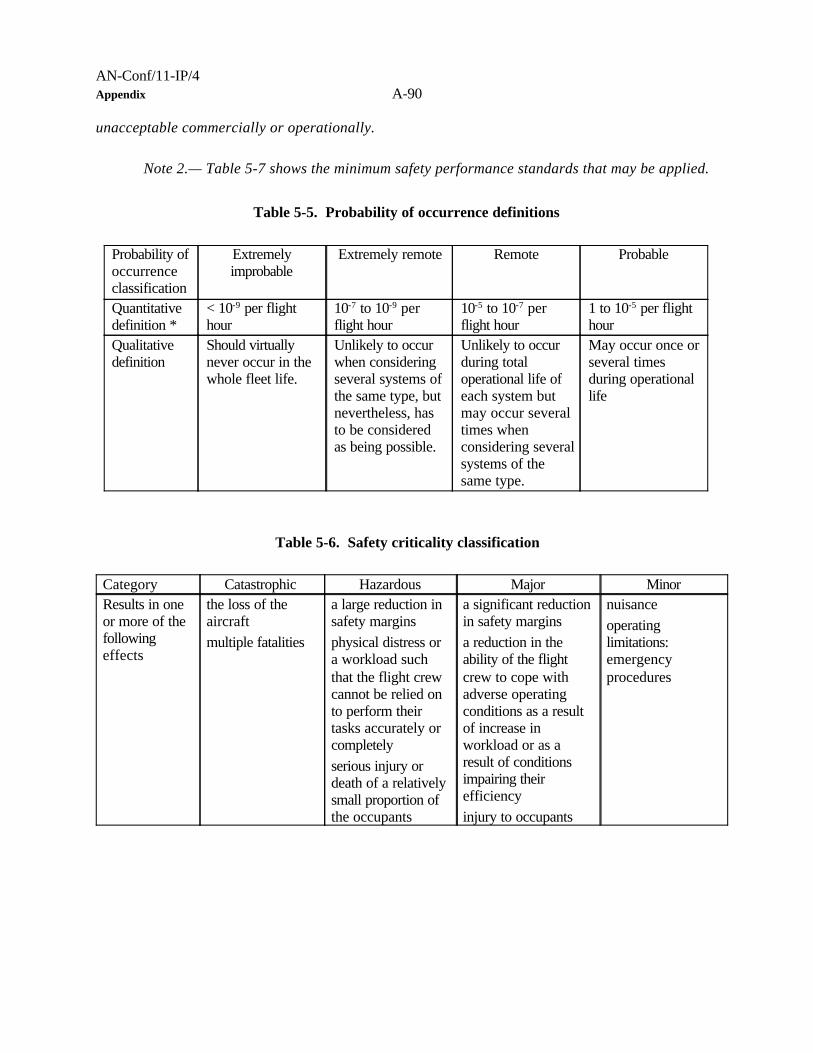
AN-Conf/11-IP/4Appendix A-90
unacceptable commercially or operationally.
Note 2.— Table 5-7 shows the minimum safety performance standards that may be applied.
Table 5-5. Probability of occurrence definitions
Probability ofoccurrenceclassification
Extremelyimprobable
Extremely remote Remote Probable
Quantitativedefinition *
< 10-9 per flighthour
10-7 to 10-9 perflight hour
10-5 to 10-7 perflight hour
1 to 10-5 per flighthour
Qualitativedefinition
Should virtuallynever occur in thewhole fleet life.
Unlikely to occurwhen consideringseveral systems ofthe same type, butnevertheless, hasto be consideredas being possible.
Unlikely to occurduring totaloperational life ofeach system butmay occur severaltimes whenconsidering severalsystems of thesame type.
May occur once orseveral timesduring operationallife
Table 5-6. Safety criticality classification
Category Catastrophic Hazardous Major MinorResults in oneor more of thefollowingeffects
the loss of theaircraft multiple fatalities
a large reduction insafety marginsphysical distress ora workload suchthat the flight crewcannot be relied onto perform theirtasks accurately orcompletelyserious injury ordeath of a relativelysmall proportion ofthe occupants
a significant reductionin safety marginsa reduction in theability of the flightcrew to cope withadverse operatingconditions as a resultof increase inworkload or as aresult of conditionsimpairing theirefficiencyinjury to occupants
nuisanceoperatinglimitations:emergencyprocedures

AN-Conf/11-IP/4A-91 Appendix
Table 5-7. Risk tolerability matrix
Quantitativeprobability ofoccurrence
1 10-1 10-2 10-3 10-4 10-5 10-6 10-7 10-8 10-9
*JAR 25Qualitative
probability ofoccurrence
Frequent Reasonablyprobable
Remote Extremelyremote
Extremelyimprobable
Classificationof effect
Minor Major Hazardous Catastrophic
5.6 CERTIFICATION
5.6.1 All ground equipment that forms an essential element of an A-SMGCS should be certified for its useand be regularly inspected or reviewed. The aerodrome operator should have certified maintenanceprocedures established for the ground equipment that is essential to the performance of an A-SMGCS.
5.6.2 The certification of airborne equipment should be covered by aircraft certification procedures.
5.6.3 All software used for an A-SMGCS should be certified through a standard software certificationprocedure.
5.6.4 Any new application or change to an A-SMGCS should be evaluated by the regulatory authority forcompliance of the system with the operational requirements. The evaluation should be followed by a formalapproval. Additional requirements or limitations of the operational use could be stated.
5.6.5 The aerodrome operator and the ATC service provider have responsibility for the training andmaintenance procedures for personnel and equipment under its jurisdiction. In the certification process, theyshould be able to demonstrate that they can perform all tasks required for the proper functioning of an A-SMGCS.
5.6.6 The manufacturer of an A-SMGCS has responsibility for the proper documentation of the systemconcept and design. Furthermore, evidence of system capabilities should be provided. Depending on the localsituation, the manufacturer could have to deal either with the regulatory authority or with the purchasingorganization.
____________________

AN-Conf/11-IP/4Appendix A-92
GLOSSARY
Note.— Some terms provided below are taken from existing ICAO documents, e.g. Annex 14.
Advanced surface movement guidance and control system (A-SMGCS). A system providing routing,guidance and surveillance for the control of aircraft and vehicles in order to maintain the declared surfacemovement rate under all weather conditions within the aerodrome visibility operational level (AVOL) whilstmaintaining the required level of safety.
Aerodrome. A defined area on land or water (including any buildings, installations, and equipment) intendedto be used either wholly or in part for arrival, departure and surface movement of aircraft.
Aerodrome visibility operational level (AVOL). The minimum visibility at or above which the declaredmovement rate can be sustained.
Airport authority. The entity responsible for the operational management of the airport.
Alert. An indication of an existing or pending situation during aerodrome operations, or an indication ofabnormal A-SMGCS operation, that requires attention and/or action.
Note.— The term alert covers warnings, cautions, advisories and alarms reflecting different levelsof urgency or equipment performance.
Apron. A defined area, on a land aerodrome, intended to accommodate aircraft for purposes of loading orunloading passengers, mail or cargo, fuelling, parking or maintenance.
Apron management service. A service provided to regulate the activities and movement of aircraft andvehicles on an apron.
A-SMGCS capacity. The maximum number of simultaneous movements of aircraft and vehicles that thesystem can safely support with an acceptable delay commensurate with the runway and taxiway capacityat a particular aerodrome.
Conflict. A situation where there is a risk for collision between aircraft and/or vehicles.
Identification. The correlation of a known aircraft or vehicle call sign with the displayed target of thataircraft or vehicle on the display of the surveillance system.
Incursion. The unauthorized or unplanned entry by an aircraft, vehicle or obstacle into the protected areassurrounding an active runway, taxiway or apron.

AN-Conf/11-IP/4A-93 Appendix
Manoeuvring area. That part of an aerodrome to be used for the take-off, landing and taxiing of aircraft,excluding aprons.
Movement area. That part of an aerodrome to be used for the take-off, landing and taxiing of aircraft,consisting of the manoeuvring area and apron(s).
Note.— For A-SMGCS, the movement area does not include passive stands, empty stands and thoseareas of the apron(s) that are exclusively designated to vehicle movements.
Obstacle. All fixed (whether temporary or permanent) and mobile obstacles, or parts thereof, that are locatedon an area intended for the surface movement of aircraft or that extend above a defined surface intendedto protect aircraft in flight.
Reversion time. Maximum time for reversion to manual light control to be completed.
Road. An established surface route on the movement area meant for the exclusive use of vehicles.
Route. A track from a defined starting point to a defined endpoint on the movement area.
Stand. A designated area on an apron intended to be used for the parking of an aircraft. These stands canbe:
a) active stand — a stand which is occupied by a stationary aircraft with engines operating or on which anaircraft is moving or which is being approached by an aircraft;
b) passive stand — a stand which is occupied by a stationary aircraft with engines not operating; or
c) empty stand — a stand which is vacant and not being approached by an aircraft.
Surveillance. A function of the system which provides identification and accurate position information onaircraft, vehicles and obstacles within the designated area.
System accuracy. A degree of conformance between the estimated or measured value and the true value.
Note.- For A-SMGCS this includes the position and the speed.
System availability. The ability of an A-SMGCS to perform a required function at the initiation of theintended operation within an area covered by an A-SMGCS.
System continuity. The ability of an A-SMGCS to perform its required function without non-scheduled

AN-Conf/11-IP/4Appendix A-94
interruption during the intended operation in an area covered by an A-SMGCS.
System integrity. System integrity relates to the trust which can be placed in the correctness of theinformation provided by an A-SMGCS. This includes the ability of an A-SMGCS to provide timely and validalerts to the user(s) when an A-SMGCS must not be used for the intended operation.
System reliability. The ability of an A-SMGCS to perform a required function under given conditions fora given time interval.
Target. An aircraft, vehicle or obstacle, which is displayed on a surveillance display.
Target level of safety (TLS). The probability of an accident (fatal or hull loss) during aircraft movement onthe aerodrome.
____________________

AN-Conf/11-IP/4A-95 Appendix
Appendix A
A-SMGCS CATEGORIZATION
1. INTRODUCTION
1.1 To provide guidance on the level of A-SMGCS appropriate to a specific aerodrome it is necessary toconsider:
a) visibility conditions;b) traffic density; andc) aerodrome layout.
1.2 The criteria proposed for traffic density and visibility conditions are based on the Manual of SurfaceMovement Guidance and Control Systems (SMGCS) (Doc 9476).
2. VISIBILITY CONDITIONS
2.1 An additional low visibility condition has been included to take into account the conditions below thesecurrently specified in Doc 9476. The visibility conditions are as follows:
a) Visibility condition 1
Visibility sufficient for the pilot to taxi and to avoid collision with other traffic on taxiways and atintersections by visual reference, and for personnel of control units to exercise control over all trafficon the basis of visual surveillance;
b) Visibility condition 2
Visibility sufficient for the pilot to taxi and to avoid collision with other traffic on taxiways and atintersections by visual reference, but insufficient for personnel of control units to exercise controlover all traffic on the basis of visual surveillance;
c) Visibility condition 3
Visibility sufficient for the pilot to taxi but insufficient for the pilot to avoid collision with other trafficon taxiways and at intersections by visual reference, and insufficient for personnel of control unitsto exercise control over all traffic on the basis of visual surveillance. For taxiing this is normally takenas visibilities equivalent to a RVR of less than 400 m but more than 75 m; and

AN-Conf/11-IP/4Appendix A-96
d) Visibility condition 4
Visibility insufficient for the pilot to taxi by visual guidance only. This is normally taken as a RVRof 75 m or less.
Note.— The above visibility conditions apply for both day and night operations.
2.2 In selecting A-SMGCS modules for a particular aerodrome, in addition to the main criteria describedabove, effects of short-term transitory factors, such as low angle sun glare, twilight, differing day and nightviewing conditions etc. should also be considered.
2.3 Aerodrome movement rates may include short term peak loads in excess of normal movement rates,which may result in difficulty for ATC in maintaining awareness of the traffic situation by visual means alone.
3. TRAFFIC DENSITY
3.1 Traffic density is measured from the mean busy hour independent of visibility condition.
3.2 Traffic density is divided into three categories:
a) Light (L)
No more than 15 movements per runway or typically less than 20 total aerodrome movements;
a) Medium (M)
16 to 25 movements per runway or typically between 20 to 35 total aerodrome movements; and
c) Heavy (H)
26 or more movements per runway or typically more than 35 total aerodrome movements.
4. AERODROME LAYOUT
4.1 For aerodrome layout, three levels have been established as follows:
a) Basic (B)
An aerodrome with one runway with one taxiway to one apron area;
b) Simple (S)

AN-Conf/11-IP/4A-97 Appendix
An aerodrome with one runway, having more than one taxiway to one or more apron areas;
c) Complex (C)
An aerodrome with more than one runway, having many taxiways to one or more apron areas.
5. Aerodrome types
5.1 By identifying each of the appropriate criteria it is possible to determine the necessary SMGCS or A-SMGCS modules to support the operational requirements at a specific aerodrome based on the intendedminimum visibility for operations.
5.2 Considering the criteria at 2.1 , 3.2 and 4.1 above, there are 36 combinations which may be related to anaerodrome type and these can be grouped for each visibility condition as shown below.
Visibility conditions
1 2 3 4
T-1:(B)(L) T-10:(B)(L) T-19:(B)(L) T-28:(B)(L)
T-2:(B)(M) T-11:(B)(M) T-20:(B)(M) T-29:(B)(M)
T-3:(B)(H) T-12:(B)(H) T-21:(B)(H) T-30:(B)(H)
T-4:(S)(L) T-13:(S)(L) T-22:(S)(L) T-31:(S)(L)
T-5:(S)(M) T-14:(S)(M) T-23:(S)(M) T-32:(S)(M)
T-6:(S)(H) T-15:(S)(H) T-24:(S)(H) T-33:(S)(H)
T-7:(C)(L) T-16:(C)(L) T-25:(C)(L) T-34:(C)(L)
T-8:(C)(M) T-17:(C)(M) T-26:(C)(M) T-35:(C)(M)
T-9:(C)(H) T-18:(C)(H) T-27:(C)(H) T-36:(C)(H)
Note.— Appendix C shows a grouping of the aerodrome types appropriate to the level ofimplementation of A-SMGCS after considering the necessary functional requirements to maintainA-SMGCS capacity.
____________________

AN-Conf/11-IP/4Appendix A-98
Appendix B
A-SMGCS IMPLEMENTATION LEVELS
Criteria for the categorization of aerodromes on the basis of visibility conditions, traffic density andaerodrome layout are given in Appendix B. The appropriate level of functional implementation for a particularaerodrome can be addressed through an identification of the criteria that apply. There are 36 possibleaerodrome type criteria combinations, 4 functional criteria and 3 user groups to consider. Overall the numberof options is too large to be of practical assistance to anyone tasked with defining the level of implementationthat is appropriate for a given aerodrome. The table below is offered as one means of grouping A-SMGCSimplementation into 5 levels that together cover all cases. It shows that the 4 basic functions are providedat all levels. Within the table, the role played by automation and avionics increases progressively through thelevels. Level V is related to the most demanding aerodrome requirements where the level of automation isthe highest.
Aerodrome types
User Surveillance Control Routing
Guidance Level
Conflictprediction
and/ordetection
Conflictanalysi
s
Conflictresolution
Ground Onboar
d
1* 2* 3* 4*
T-1: 1:(B)(L)
T-2: 1:(B)(M)
T-3: 1:(B)(H)
T-4: 1:(S)(L)
Controller X X X X X I
P i l o t / V e h i c l edriver
X X X X
System
T-5: 1:(S)(M)
T-6: 1:(S)(H)
T-7: 1:(C)(L)
T-10: 2:(B)(L)
T-11: 2:(B)(M)
T-13: 2:(S)(L)
Controller X X X X X II
P i l o t / V e h i c l edriver
X X X X X
System X X
T-8: 1:(C)(M)
T-12: 2:(B)(H)
T-14: 2:(S)(M)
T-16: 2:(C)(L)
T-19: 3:(B)(L)
T-20: 3:(B)(M)
T-22: 3:(S)(L)
Controller X X X X III
P i l o t / V e h i c l edriver
X X1) X1) X
System X X X X X

AN-Conf/11-IP/4A-99 Appendix
T-9: 1:(C)(H)
T-15: 2:(S)(H)
T-17: 2:(C)(M)
T-18: 2:(C)(H)
T-21: 3:(B)(H)
T-23: 3:(S)(M)
T-24: 3:(S)(H)
T-25: 3:(C)(L)
T-26: 3:(C)(M)
T-27: 3:(C)(H)
Controller X X X IV
P i l o t / V e h i c l edriver
X X1) X1) X
System X X X X X X
T-28: 4:(B)(L)
T-29: 4:(B)(M)
T-30: 4:(B)(H)
T-31: 4:(S)(L)
T-32: 4:(S)(M)
T-33: 4:(S)(H)
T-34: 4:(C)(L)
T-35: 4:(C)(M)
T-36: 4:(C)(H)
Controller X X X V
P i l o t / V e h i c l edriver
X X
System X X X X X X
1* Painted centre line and taxiway guidance signs Note 1): Does not apply in visibility condition 3
2* Fixed centre line lights
3* Manual switched centre line lights
4* Automatic switched centre line lights
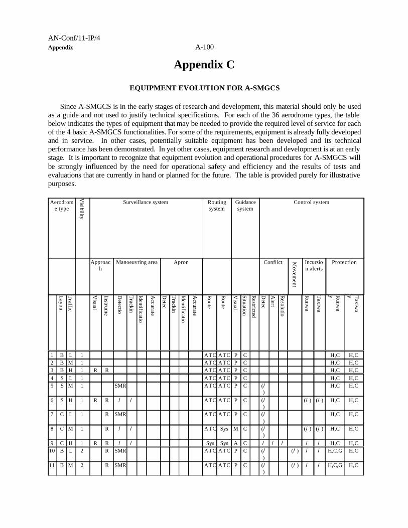
AN-Conf/11-IP/4Appendix A-100
Appendix C
EQUIPMENT EVOLUTION FOR A-SMGCS
Since A-SMGCS is in the early stages of research and development, this material should only be usedas a guide and not used to justify technical specifications. For each of the 36 aerodrome types, the tablebelow indicates the types of equipment that may be needed to provide the required level of service for eachof the 4 basic A-SMGCS functionalities. For some of the requirements, equipment is already fully developedand in service. In other cases, potentially suitable equipment has been developed and its technicalperformance has been demonstrated. In yet other cases, equipment research and development is at an earlystage. It is important to recognize that equipment evolution and operational procedures for A-SMGCS willbe strongly influenced by the need for operational safety and efficiency and the results of tests andevaluations that are currently in hand or planned for the future. The table is provided purely for illustrativepurposes.
Aerodrome type
Visibility
Surveillance system Routingsystem
Guidancesystem
Control system
Approach
Manoeuvring area Apron Conflict Movem
ent
Incursion alerts
Protection
Layou
Traffic
Visual
Instrume
Detectio
Trackin
Identificatio
Accurate
Detec
Trackin
Identificatio
Accurate
Route
Route
Visual
Situation
Restricted
Detec
Alert
Resolutio
Runw
a
Taxiw
a
Runw
ay T
axiwa
y
1 B L 1 ATC ATC P C H,C H,C2 B M 1 ATC ATC P C H,C H,C3 B H 1 R R ATC ATC P C H,C H,C4 S L 1 ATC ATC P C H,C H,C5 S M 1 SMR ATC ATC P C (/
)H,C H,C
6 S H 1 R R / / ATC ATC P C (/)
(/) (/) H,C H,C
7 C L 1 R SMR ATC ATC P C (/)
H,C H,C
8 C M 1 R / / ATC Sys M C (/)
(/) (/) H,C H,C
9 C H 1 R R / / Sys Sys A C / / / / / H,C H,C10 B L 2 R SMR ATC ATC P C (/
)(/) / / H,C,G H,C
11 B M 2 R SMR ATC ATC P C (/)
(/) / / H,C,G H,C

AN-Conf/11-IP/4A-101 Appendix
12 B H 2 R R / / ATC Sys M C (/)
(/) / / H,C,G H,C
13 S L 2 R SMR ATC ATC P C (/)
(/) / / H,C,G H,C
14 S M 2 R / / / ATC Sys M C (/)
(/) / / H,C,G H,C
15 S H 2 R R / / / Sys Sys A C / / / (/) / / H,C,G H,C16 C L 2 R / / / ATC Sys M C (/
)(/) / / H,C,G H,C
17 C M 2 R / / / Sys Sys A C / / / (/) / / H,C,G,S
H,C,T
18 C H 2 R R / / / Sys Sys A C / / / / / / H,C,G,S
H,C,T
19 B L 3 R / / / / ATC Sys M C (/)
/ / / / / H,C,G,S
H,C,T
20 B M 3 R / / / / ATC Sys M C (/)
/ / / / / H,C,G,S
H,C,T
21 B H 3 R / / / / / / / / Sys Sys A C / / / / / / H,C,G,S
H,C,T
22 S L 3 R / / / / / ATC Sys M C (/)
/ / / / / H,C,G,S
H,C,T
23 S M 3 R / / / / / / / / Sys Sys A C / / / / / / H,C,G,S
H,C,T
24 S H 3 R / / / / / / / / Sys Sys A C / / / / / / H,C,G,S
H,C,T
25 C L 3 R / / / / / / / / Sys Sys A C / / / / / / H,C,G,S
H,C,T
26 C M 3 R / / / / / / / / Sys Sys A C / / / / /,E /,E H,C,G,S
H,C,T
27 C H 3 R / / / / / / / / Sys Sys A C / / / / /,E /,E H,C,G,S
H,C,T
28-
36
All
All 4 R / / / / / / / / Sys Sys A,E
C,E
E / / / /,E /,E /,E H,C,G,S,E
H,C,T,E
Aerodrome types: System Modules:
Layout B = Basic R Approach radar S Switched stop bar 1)
Layout S = Simple SMR Surface movement radar 1) T Traffic lights
Layout C = Complex P Painted centre line with/without lights 1) ATC Air traffic controller
Traffic L = Light M Manually switched (block of) centre line lights 1) Sys System
Traffic M = Medium A Automatic switched centre line lights / New development required
Traffic H = Heavy C Aerodrome chart & signs 1) (/) New development desirableH Holding position marking 1) E Enhanced cockpit display
G Runway guard lights 1)
Note 1): For details see Table 2-2 of DOC 9476

AN-Conf/11-IP/4Appendix A-102
Appendix D
TARGET LEVEL OF SAFETY
1. Introduction
1.1 This appendix details the background information that was used to determine the A-SMGCS targetlevel of safety (TLS). It is necessary to allocate a portion of the TLS for an entire flight (one accident per107 operations) to the A-SMGCS taxi phase. The method chosen to determine an appropriate TLS for anoperation was to base it on the historical accident and movement rates within the European Civil AviationConference (ECAC) area. A similar exercise conducted in the United States is also outlined. Both producecomparable results.
2. ECAC accident data
2.1 This study [Ref. 1] was based on the ICAO “Accident/Incident Data Reporting System” (ADREP)database and the number of movements on ECAC aerodromes extracted from ICAO statistics yearbooks,Doc 9180. Flight data from the EUROCONTROL Central Flight Management Unit (CFMU) were used toanalyse the number of movements but, since this information refers to flights since 1992, was only used asreference information.
2.2 The ADREP database was used to collect the number and characteristics of ground movementaccidents in overall ECAC members’ States since 1980. There are 627 recorded accidents from 27 ECACStates; of which 52 accidents were fatal or caused total aircraft destruction. Of these fatal or hull-lossaccidents, 2 occurred as a result of taxi or runway operations.
Note 1.— An accident in Armenia in 1998 was not included because there was no movementdata concerning this State. The other 575 accidents, even if they had serious consequences or were“near-misses”, were not included.
Note 2.— The accident on Tenerife in 1977 involving two B747s was not included because oflack of accident and traffic data before 1980. Similarly, the fatal runway incursion at Paris in 2000was not included due to lack of traffic data.
2.3 From 1980 to 1996, there were 150,612,893 movements in the ECAC area. However, data have yetto be published for the period 1997 to 1999; therefore, an annual growth of 5 per cent was estimated. Sincethe data refers to principal aerodromes only, a factor of 10 per cent was applied to the total number of aircraftmovements to take into consideration the traffic at non-principal aerodromes. This gives a total number ofmovements of 165,674,182.
2.4 The above data give an ECAC-wide taxi accident rate of 2/165674182 = 1.2 x 10⁻⁸ per operation. Ifwe consider that the average taxi time of an aircraft does not exceed 6 minutes, the risk per hour will be 1.2x 10⁻⁶ per hour. This value compares with similar analysis, conducted in the United States for A-SMGCSTLS using worldwide and United States’ accident data, which is outlined below.

AN-Conf/11-IP/4A-103 Appendix
3. Worldwide and United States accident data
3.1 An analysis to determine a TLS for A-SMGCS that was performed by a subgroup of the ICAO AllWeather Operations Panel in 1997 [Ref. 3] considered accident data for the landing and taxi phases of flightand compared the calculated risk of a fatal accident within the global aerodrome operations TLS of 107..3.2 An analysis of worldwide accident data revealed a fatal accident rate (1985 to 1994) of 1.8 x 10⁻⁶
per operation and taxi accidents account for 5 per cent of fatal accidents. Therefore the worldwide fatal taxiaccident rate is 9.0 x 10⁻⁸ per operation.
3.3 An analysis of National Transportation Safety Board (NTSB) data reveals a fatal accident rate (1985to 1994) is 0.56 x 10⁻⁶ per operation and fatal taxi accidents account for 11 per cent of all fatal accidents.Therefore, the United States’ fatal taxi accident rate is 6.2 x 10⁻⁸ per operation.
3.4 The total TLS defined in developing the approach and landing required navigation performance (RNP)was 1.5 x 10⁻⁷ per mission. The final approach and landing allocation was 1.0x10⁻⁸ per operation.
3.5 The TLS for A-SMGCS, encompassing the taxi phase of the total flight operations, must fit withinthis overall mission TLS. Another factor is that the accident data reflect accidents due to all causes, whereasA-SMGCS related accidents would constitute only a portion of taxi accidents. Therefore the A-SMGCS TLSshould not receive the entire allocation of risk related to the taxi phase of operation.
3.6 From worldwide accident data and NTSB data for aircraft operations in the United States, the fataltaxi accident rates are similar (9.0 vs. 6.2 x 10⁻⁸ per operation). As stated before, the total mission TLS istargeted to be 1.0 x 10⁻⁷. The final approach and landing phase was allocated 1.0 x 10⁻⁸. Similarly, the otherphases of flight have allocations that use only a small portion of the overall TLS. Therefore, the taxi phaseshould be allocated a comparable portion. Based on the above considerations, the A-SMGCS TLS is 1.0 x10⁻⁸ (per operation). Although the time periods over which the data have been evaluated, it was consideredthat the margin of 6-9 over the historical accident rate was is in line with the allocations of TLS to the variousphases of flight used for the approach and landing RNP and, therefore, may be considered a fair conclusion.
____________________

AN-Conf/11-IP/4Appendix A-104
1 European Commission DG VII: Air Transport/Airports/Task 4.3.1/44
Appendix E
A-SMGCS RESEARCH
1. Introduction
1.1 This appendix describes some of the A-SMGCSs that have been the subject of research projects oroperational trials in Europe and the United States.
1.2 The purpose of this appendix is not only to describe A-SMGCS but to provide some information onthe type of components or sub-systems that may be used to develop an A-SMGCS suitable for an individualaerodrome.
2. Demonstration Facilities for Aerodrome Movement Management (DEFAMM)
2.1 The Demonstration Facilities for Aerodrome Movement Management (DEFAMM1) was a researchproject carried out by fifteen European partners from industry, research institutes, aerodrome and ATCauthorities and sponsored by the European Commission. In DEFAMM, various prototype sub-systemscovering all A-SMGCS main functions were demonstrated in operational environments, including fourEuropean aerodromes. This was the first large-scale integrated system demonstration for aerodrome surfacetraffic management on a European level. The project commenced on 1 December 1995 and ended on 31March 1999.
2.2 Four aerodromes participated in the demonstration of the A-SMGCS. Not all of the functions wereimplemented at each demonstration site. This was because the total range of the DEFAMM functions formeda complex system and a single test site, being also an operational aerodrome, would have been completelyoverloaded. Furthermore, it was desirable to demonstrate that an A-SMGCS could be profitably embeddedin different environments with a variety of aerodrome facilities and topological constraints. A furtheradvantage was the ability to use several independent test environments for systems such as positioningreference and digitized aerodrome maps.
2.3 DEFAMM functional demonstration
Surveillance function
2.3.1 As the architecture in Figure 4 shows, the surveillance function was realized by two non-cooperativesensors and two cooperative sensors. The two non-cooperative sensors were the existing surface movementradar (SMR) with the new radar data extractor electronic scanning radar directly delivering digital targetreports. The two cooperative sensors comprised the prototype Mode S multi-lateration system with a ModeS central station (mainly for aircraft detection and identification) and a differential global navigation satellitesystem (D-GNSS) subsystem with a D-GNSS central station (mainly for vehicles). A cooperative sensor for

AN-Conf/11-IP/4A-105 Appendix
vehicles was also demonstrated to enhance the surveillance capabilities.
2.3.2 The sensor data fusion was implemented on the sensor data processing, which combined the foursensor types and used data from the aerodrome surveillance radar (ASR) to deliver a unique picture of thetraffic situation. The sensor data fusion is a software product, and its task is to track and filter thesurveillance data, to provide identification information of controlled vehicles and to monitor the trafficsituation.
Control function
2.3.3 The subsystem for conflict handling was realized on a workstation of the sensor data processingcomputers. The main functions implemented were the detection and handling of:
a) area violation and intrusion;
b) runway incursion;
c) crossing conflicts;
d) roll-up and opposite traffic conflicts;
e) deviation from assigned route; and
f) deviation from assigned time slots.
Planning function
2.3.4 The following basic planning functions were implemented:
a) proposed movement plans (routes and time slots) provided to the controller for:
1) arriving aircraft when it arrived at final approach;
2) departing aircraft after start-up request;
3) selected aircraft or vehicle on request;
b) the means to edit and modify the plans at any time in terms of:
1) route change for new destination;
AN-Conf/11-IP/4Appendix A-106
2) route change for the same destination;
3) change the plans with respect to new time slots;
c) the means to negotiate the plans with the controller:
1) issue plan proposals to the HMI;
2) change status when the plan is accepted by the controller;
3) change status when the plan is cleared by the controller; and
d) cleared plans to the guidance processing function.
Guidance function
2.3.5 The guidance processor permitted:
a) manual or automated switching of centre line light segments and stop bars according to the taxiplan and the current situation of the aircraft or vehicles; and
b) clearance negotiation and automated transmission of taxi plan and guidance commands via datalink and the on-board display system.
2.3.6 Guidance with the aerodrome ground lighting was implemented to:
a) guide the aircraft or vehicles according to the route of the cleared plan with selectivelyswitchable taxiway centre line lights;
b) allow manual switching of the taxiway centre line lights; and
c) allow manual switching of the stop bars.
2.3.7 Guidance with the on-board display (pilot/driver assistance system) was implemented to:
a) display the aircraft or vehicles’ own position on the aerodrome with respect to the assigned route;
b) support the negotiation of taxi plans (request clearance, receive clearance, accept clearance);and
c) display the cleared movement plan (taxi route and time slots).
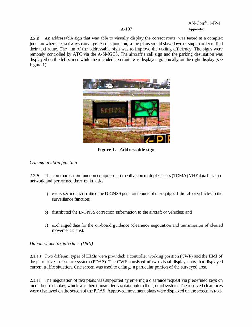
AN-Conf/11-IP/4A-107 Appendix
Figure 1. Addressable sign
2.3.8 An addressable sign that was able to visually display the correct route, was tested at a complexjunction where six taxiways converge. At this junction, some pilots would slow down or stop in order to findtheir taxi route. The aim of the addressable sign was to improve the taxiing efficiency. The signs wereremotely controlled by ATC via the A-SMGCS. The aircraft’s call sign and the parking destination wasdisplayed on the left screen while the intended taxi route was displayed graphically on the right display (seeFigure 1).
Communication function
2.3.9 The communication function comprised a time division multiple access (TDMA) VHF data link sub-network and performed three main tasks:
a) every second, transmitted the D-GNSS position reports of the equipped aircraft or vehicles to thesurveillance function;
b) distributed the D-GNSS correction information to the aircraft or vehicles; and
c) exchanged data for the on-board guidance (clearance negotiation and transmission of clearedmovement plans).
Human-machine interface (HMI)
2.3.10 Two different types of HMIs were provided: a controller working position (CWP) and the HMI ofthe pilot driver assistance system (PDAS). The CWP consisted of two visual display units that displayedcurrent traffic situation. One screen was used to enlarge a particular portion of the surveyed area.
2.3.11 The negotiation of taxi plans was supported by entering a clearance request via predefined keys onan on-board display, which was then transmitted via data link to the ground system. The received clearanceswere displayed on the screen of the PDAS. Approved movement plans were displayed on the screen as taxi-

AN-Conf/11-IP/4Appendix A-108
route, with time slots at way-points. The positions of the aircraft or vehicle and other equipped aircraft orvehicles were also displayed on the PDAS screen.
3. Operational benefit evaluation by testing an A-SMGCS (BETA project)
3.1 The BETA project was also funded by the European Commission during 2000/2001. The projectinvolved the operational testing of system components, based on early drafts of this manual, installed at threeEuropean airports. The systems comprised surveillance sensor equipment and computers from differentmanufacturers, integrated with the existing airport and ATC equipment and infrastructure, to provide the firstfull-scale implementation of A-SMGCS within Europe. See Figure 5.
3.2 The system testing covered the following aspects:
a) surveillance;
1) detection and presentation of traffic and obstacles on the aerodrome movement area andapproaches;
2) automatic identification of suitably equipped cooperating traffic, including arriving aircraft;
3) departing aircraft, if equipped with active Mode-S transponders;
4) participating vehicles (GP&C and/or Mode-S equipped test vans and service vehicles);
5) manual identification of other targets;
b) alerting;
1) runway occupied/runway incursion alerting for arrivals and departures;
2) restricted area intrusion alerting;
3) crossed stop bar alerting;
4) route deviation alerting;
c) planning;
1) flight plan presentation;
2) creation, modification, and editing of flight plans (including VFR and vehicles);

AN-Conf/11-IP/4A-109 Appendix
2 “1998 Airport Surface Operations Safety Plan to Prevent Runway Incursions and Improve Surface Operations,” Runway Incursion ProgramOffice (ATO-102), FAA; 1998.
3) electronic flight strips;
4) handover;
5) departure sequence proposal;
6) selection of taxiway route;
d) guidance;
1) stop bars;
2) on board guidance;
3) clearance delivery;
4) route indication;
e) controller HMI;
1) traffic situation display; and
2) planning display.
3.3 The BETA equipment was provided in a non-redundant configuration, focussing on data integrity,accuracy and usability.
4. FAA runway incursion reduction programme
4.1 Trials started in year 2000 in the United States under the FAA Runway Incursion ReductionProgramme2 (RIRP) to evaluate new technologies for A-SMGCS.
4.2 RIRP surveillance system
4.2.1 Figure 6 shows a block diagram of the RIRP surveillance system. At the heart of the system is thesurface surveillance data server (SSDS). The SSDS receives surveillance and flight plan information froma variety of sources and “fuses” the information into one optimal report for user display. The surveillanceinformation comes from a variety of cooperative and non-cooperative sensors, including terminal and surface

AN-Conf/11-IP/4Appendix A-110
radar, inductive loops, automatic dependent surveillance—broadcast (ADS-B), and multi-lateration. The flightplan information is received from the local automation system, an automated radar terminal system (ARTS)via the flight plan unit. The majority of information is passed between subsystems over the LAN. It isexpected that the system will be modular to meet the surveillance requirements of various aerodromes in theUnited States.
4.3 Sensor inputs
4.3.1 The RIRP prototype demonstration system will accept various surveillance inputs, including thefollowing:
a) ASDE-3
The ASDE-3 is a primary radar intended for aerodrome surface surveillance. It maintains a one-second update rate and will provide the SSDS with raw digitized video. The raw video will beprocessed within the SSDS and position reports will be provided for fusion.
b) ASR-9
The ASR-9 is a terminal radar system that covers a 110 km (60 NM) range. The ASR-9maintains an approximate five-second update rate. The RIRP system will utilize position data onarriving aircraft from the ASR-9.
c) aerodrome target identification system (ATIDS)
ATIDS is a multi-lateration system designed to track and provide identification of aircraft in thecovered area of the aerodrome surface. This includes the complete surface movement area(taxiways and runways), 3 km arrival corridors and 90 m (300 ft) above the surface. Mode Stransponder equipped aircraft are tracked using the “squitters” periodically transmitted from theaircraft. Transmissions are then received by receiver/transmitters located around the aerodrome.Time difference of arrival (TDOA) calculations is performed on the receptions to produce aposition report. Additionally, ATIDS can receive ADS-B transmissions on the 1090 MHzfrequency to attain position and other information contained in the aircraft transmissions.
d) loop technology
The RIRP system also utilizes loop technology in the loop sensor sub-system (LSS), to aid in thereduction of gaps in coverage. Inductive loops, similar to those used in automotive traffic systems(e.g. traffic light triggering), are placed in the taxiway. An aircraft or vehicle passing over a loopproduces nose and tail detection that can be processed into position reports by the surveillanceserver.
e) vehicle ADS-B

AN-Conf/11-IP/4A-111 Appendix
The vehicle ADS-B system utilizes ADS-B concepts to provide surveillance of aerodromesurface vehicles to controllers as well as to provide situational awareness to vehicle operators.Each equipped vehicle determines its own position utilizing D-GNSS technology and broadcaststhe vehicle position and its identification to three base stations covering the aerodrome. A masterbase station that interfaces with the RIRP LAN via the data link manager gathers this positionand identification information.
f) ARTS-IIIE
The ARTS-IIIE automation system provides flight plan information for arriving and departingaircraft.
g) local area augmentation system (LAAS)
A LAAS ground station provides D-GNSS corrections. These corrections will be available onthe LAN through the data link manager for various systems to up-link them to aircraft andvehicles.
4.4 Outputs
4.4.1 The system also has the capability to provide situational awareness of aircraft and other targets fromthe SSDS, as well as runway hold bar information, to users, including the following:
a) aircraft displays
traffic and safety alerts can be up-linked, via the data link manager utilizing the vehicle ADS-Bsystem, from the SSDS to developmental displays in aircraft. Figures 2 and 3 illustrate twomoving map displays for use in aircraft or vehicles to indicate routing and conflict alertinformation.

AN-Conf/11-IP/4Appendix A-112
Figure 2. Cockpit arrival moving map display
Figure 3. Cockpit departure moving mapdisplay
b) controller displays

AN-Conf/11-IP/4A-113 Appendix
the SSDS will provide a colour display for ATC. For each aircraft, the display will show anoptimal position report and identification. Additionally, the display will show incursion alerts andholding position information.
c) data link manager (DLM)
the DLM serves as a gateway between the RIRP LAN and external systems. These systemsinclude the vehicle ADS-B system, the LAAS ground station, and future data link communicationprojects. The DLM provides an interface for target reports to be exchanged between the vehicleADS-B system and the RIRP LAN, as well as providing the safety alerts from the RIRP systemto be up-linked to vehicles and aircraft.
d) vehicle operator displays
as previously mentioned, the vehicle ADS-B system will provide position, identification and safetyalert information to vehicle operators.
4.5 On board guidance
4.5.1 The RIRP system trials included the ability of an aircraft (or vehicle) to perform and maintain a taxi-route in visibility conditions of 75 m RVR or less.
4.5.2 In visibility condition 4, the operational and performance requirements for the surveillance, routingand control functions should account for the ability of an aircraft to self-navigate on the movement area.These functions may be wholly contained within the avionics or provided, by datalink, from an aerodrome A-SMGCS.
4.5.3 Position estimation error values, as outlined in Table 10 are based on an allocation of the total systemerrors relative to minimum aerodrome runway, taxiway and apron design requirements specified in Annex14, Volume 1.
4.5.4 The allocations are made to accommodate sufficient path steering errors for various aircraft typesand based on operational and simulator performance data.
4.5.5 The longitudinal position estimation errors assigned in Table 1 are based on the assumption that theguidance sensor achieves the same level of performance in all horizontal directions.
Table 1. Lateral and longitudinal position estimation errors required for on-board guidance
Aerodrome code
Lateral and longitudinal positionestimation errors (95%, m)

AN-Conf/11-IP/4Appendix A-114
Rapidexit,
normaland aprontaxiways
Standtaxi-lane
Stand
A 0.4 0.4 0.3B 0.6 0.4 0.3C 0.8 0.5 0.4D 1.1 0.6 0.5E 1.1 0.6 0.5
4.5.6 As an example, Figure 7 illustrates the key taxiway design standards for aerodrome reference codeletter E, which gives a 15.5 m margin between the wing tips and any objects, including the wings of aircrafton parallel taxiways. The minimum margin between the main wheels and taxiway edge is 4.5 m. Thestandards also recommend a 10.5 m shoulder, thus yielding a 15 m margin between the wheels and outer edgeof the shoulder. The result is that the aircraft can deviate by 15 m from the taxiway centre line before thereis risk of an incident, and therefore the containment limit is defined to be this value.
4.5.6 The containment limit of 15 m is applicable only to aerodromes of codes D and E. Since the marginis less for aerodromes of codes A, B and C, the containment limit for those cases is accordingly defined tobe 8 m.
____________________
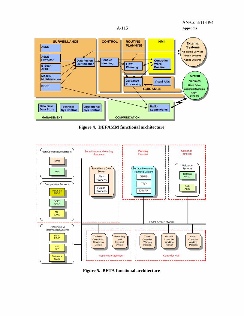
AN-Conf/11-IP/4A-115 Appendix
AircraftCtrl. Vehicles
Pilot / DriverAssistant Systems
DGPSSensors
Aircraft
VehiclesPilot / Driver
Assistant Systems
DGPSSensors
SURVEILLANCE HMI
MANAGEMENT
GUIDANCE
CONTROL ROUTINGPLANNING
Data FusionIdentification
ControllerWorkPosition
Data BaseData Store
Visual Aids
COMMUNICATION
RadioSubnetworks
ExternalSystems
Air Traffic ServicesAirport SystemsAirline Systems
ExternalSystems
Air Traffic Services
Airport Systems
Airline Systems
E-ScanASDE
Mode SMultilateration
ASDEExtractor Conflict
Handling
ASDE
TechnicalSys Control
GuidanceProcessing
FlowPlanning
OperationalSys Control
DGPS
Figure 4. DEFAMM functional architecture
TowerControllerWorkingPosition
SMR
ASRE2000
DGPSGP&C
MODE-S /ADS-B
NRN
FDPSESUP
DatalinkGP&C
ReferenceClock
AGLAMS
Co-operative Sensors
Non Co-operative Sensors
AlertProcess
FusionProcess
Surveillance DataServer
METIDP
Airport/ATMInformation Systems
GuidanceSystems
GroundControllerWorkingPosition
ApronControllerWorkingPosition
Recordingand
PlaybackSystem
TechnicalControl andMonitoring
System
Surveillance and AlertingFunctions
PlanningFunction
GuidanceFunction
System Management Controller HMI
Local Area Network
Surface MovementPlanning System
GDPS
D-MAN
TRP
Figure 5. BETA functional architecture

AN-Conf/11-IP/4Appendix A-116
Terminal AutomationInterface Unit (TAIU)
ARTS-IIIE
ATIDS
ASDE-3
AMASS
FPU
Data LinkManager
Engineering Display
LAAS
LAN
SurveillanceServer
LoopTechnology
ASR-9
Existing Equipment
Vehicle ADS-B Aircraft Display
position (blind spot)
position & identification
position, ID & alerts
position
position, ID & alerts
DGPS correctionsDGPS correction, alerts,situational awareness,position & ID
flight identification,flight plan,Arrival position
Flight plan(arrival & departure)
flight IDarrivalposition
arrivalposition& flight ID(arrival only)
Figure 6. RIRP system block diagram
Wingspan = 65m, Wheel Span = 14m
Taxiway Shoulder Width = 10.5m
Taxiway Width = 23m
Taxiway Centerline (Desired Path)
Outer Wheels Taxiway EdgeSafety Margin = 4.5m
Containment Region =Object Free Area (OFA) = ±47.5m
Wingtip to ObjectSafety Margin = 15.5m
Outer Wheels to ShoulderSafety Margin = 15m
Containment Limit
Figure 7. Taxiway design standards for aerodrome Code letter E aircraft
— END —


