60
© Retsch GmbH, 42781 Haan, Retsch-Allee 1-5, Germany 26.03.2015 0001 Manual Planetary Ball Mill PM400 Translation

© Retsch GmbH, 42781 Haan, Retsch-Allee 1-5, Germany 26.03.2015 0001
Manual
Planetary Ball Mill PM400
Translation

2
Copyright © Copyright by Retsch GmbH Haan, Retsch-Allee 1-5 D-42781 Haan Federal Republic of Germany

3

4
1 Notes on the Operating Manual ............................................................................................................ 7
1.1 Explanations of the safety warnings .................................................................................................. 8
1.2 General safety instructions ................................................................................................................ 9
1.3 Repairs ............................................................................................................................................. 10
2 Confirmation ......................................................................................................................................... 11
3 Transport, scope of delivery, installation .......................................................................................... 12
3.1 Packaging ........................................................................................................................................ 12
3.2 Transport.......................................................................................................................................... 12
3.3 Temperature fluctuations and condensed water ............................................................................. 12
3.4 Conditions for the place of installation ............................................................................................. 12
3.5 Installation of the machine ............................................................................................................... 13
3.6 Type plate description ...................................................................................................................... 13
3.7 Electrical connection ........................................................................................................................ 13
3.8 Creating interface connection .......................................................................................................... 14
3.9 Transport.......................................................................................................................................... 15
3.10 Installation of the machine ............................................................................................................... 17
3.11 Installation of the machine ............................................................................................................... 17
4 Technical data ....................................................................................................................................... 19
4.1 Use of the machine for the intended purpose.................................................................................. 19
4.2 Number of grinding stations ............................................................................................................. 20
4.3 Receptacle volume .......................................................................................................................... 20
4.4 Feed size ......................................................................................................................................... 20
4.5 Rated power .................................................................................................................................... 20
4.6 Electrical connection ........................................................................................................................ 20
4.7 Emissions......................................................................................................................................... 21
4.7.1 Noise levels .................................................................................................................................. 21
4.7.2 Measurement conditions .............................................................................................................. 21
4.8 Degree of protection ........................................................................................................................ 21
4.9 Protective equipment ....................................................................................................................... 21
4.10 Dimensions and weight .................................................................................................................... 21
4.11 Required floor space ........................................................................................................................ 21
5 Operating the machine ........................................................................................................................ 22
5.1 Views of the Instrument ................................................................................................................... 22
5.2 Overview table of the parts of the device ........................................................................................ 24
5.3 Operating elements and displays .................................................................................................... 25
5.4 Overview Table of the Operating Elements and the Display ........................................................... 25
5.5 Opening the device .......................................................................................................................... 25
5.6 Closing the device ........................................................................................................................... 25
5.7 Emergency unlocking ...................................................................................................................... 26
5.8 Inserting the grinding jar .................................................................................................................. 27
5.8.1 Clamping bolt ............................................................................................................................... 28
5.8.2 Inserting the grinding jar .............................................................................................................. 30
5.8.3 Inserting the clamping unit ........................................................................................................... 31
5.8.4 Function of the locking sleeve ..................................................................................................... 31
5.9 Releasing the grinding jar clamping mechanism ............................................................................. 32
5.10 Opening the grinding jar clamping mechanism with a counter wrench ........................................... 32

5
5.11 Power failure during grinding ........................................................................................................... 33
5.12 Mahlbehälterauswahl für unterschiedlichen Probenmaterialien ...................................................... 33
5.13 Sample quantity ............................................................................................................................... 33
5.13.1 Guides for material quantity and balls ..................................................................................... 34
5.14 Ultrafine grinding .............................................................................................................................. 34
5.15 Stacking the grinding jars ................................................................................................................ 34
5.15.1 Stacking 50ml grinding jars ...................................................................................................... 34
5.15.2 Stacking grinding jars smaller than 50ml ................................................................................. 35
5.16 Handling grinding jars ...................................................................................................................... 35
5.16.1 Carrying and gripping .............................................................................................................. 35
5.16.2 Anti-rotation device .................................................................................................................. 35
5.16.3 Heating the grinding jars .......................................................................................................... 35
5.17 Grinding jar – identification .............................................................................................................. 36
5.18 Grinding jar cleaning ........................................................................................................................ 36
5.18.1 Drying the grinding jars ............................................................................................................ 36
5.19 Closing the grinding jar .................................................................................................................... 37
6 Display and operation .......................................................................................................................... 39
6.1 Symbols in the Display Unit ............................................................................................................. 39
6.2 Display unit – operation of the device .............................................................................................. 40
6.2.1 Adjustment options using the display menu ................................................................................ 40
6.2.2 Navigating between operating modes ......................................................................................... 40
6.3 Direct access to the language menu ............................................................................................... 40
6.4 Menu structure ................................................................................................................................. 42
6.5 Operating modes ............................................................................................................................. 42
6.5.1 Manual operation ......................................................................................................................... 42
6.5.2 Program 01 to 10 ......................................................................................................................... 42
6.5.3 Basic settings ............................................................................................................................... 42
6.6 Manual operation ............................................................................................................................. 43
6.6.1 Grinding time................................................................................................................................ 43
6.6.2 Speed ........................................................................................................................................... 43
6.6.3 Interval ......................................................................................................................................... 43
6.6.4 Direction reversal ......................................................................................................................... 43
6.6.5 Pause time ................................................................................................................................... 43
6.6.6 Save parameters ......................................................................................................................... 43
6.6.7 Start in .......................................................................................................................................... 44
6.7 Programs ......................................................................................................................................... 44
6.7.1 Change program .......................................................................................................................... 44
6.7.2 Delete program ............................................................................................................................ 44
6.8 Basic settings ................................................................................................................................... 44
6.8.1 Automatic opening ....................................................................................................................... 45
6.8.2 Language ..................................................................................................................................... 45
6.8.3 Brightness .................................................................................................................................... 45
6.8.4 Date ............................................................................................................................................. 45
6.8.5 Time ............................................................................................................................................. 45
6.8.6 Acoustic warning signal ............................................................................................................... 45
6.8.7 Service ......................................................................................................................................... 45
6.8.7.1 Operating hours ................................................................................................................... 45

6
6.8.7.2 Software version of display .................................................................................................. 45
6.8.7.3 Software version of the controller ........................................................................................ 45
6.8.7.4 Update software ................................................................................................................... 45
6.8.7.4.1 Display ........................................................................................................................... 45
6.8.7.4.2 Controller ....................................................................................................................... 46
6.8.8 Safety notice ................................................................................................................................ 46
7 Fault messages ..................................................................................................................................... 47
8 Cleaning, wear and service ................................................................................................................. 48
8.1 Service .............................................................................................................................................. 48
8.1.1 Servicing the clamping unit .......................................................................................................... 49
8.1.2 Wear to the bases of the clamping unit ....................................................................................... 49
8.1.3 Rubber washer on the pressure plate ......................................................................................... 50
8.1.4 Wear to latching bracket .............................................................................................................. 50
8.2 Replacing the machine fuses ............................................................................................................ 50
8.3 Returning for service and maintenance ............................................................................................ 51
9 Disposal ................................................................................................................................................. 53
10 Index ...................................................................................................................................................... 54
Appendix .................................................................................................................................. following page

Notes on the Operating Manual
7
1 Notes on the Operating Manual
This operating manual is a technical guide on how to operate the device safely and it contains all the information required for the areas specified in the table of contents. This technical documentation is a reference and instruction manual. The individual chapters are complete in themselves.
Familiarity (of the respective target groups defined according to area) with the relevant chapters is a precondition for the safe and appropriate use of the device.
This operating manual does not contain any repair instructions. If faults arise or repairs are necessary, please contact your supplier or get in touch with Retsch GmbH directly.
Application technology information relating to samples to be processed is not included but can be read on the Internet on the respective device’s page at www.retsch.com.
Changes
Subject to technical changes.
Copyright
Disclosure or reproduction of this documentation, use and disclosure of its contents are only permitted with the express permission of Retsch GmbH.
Infringements will result in damage compensation liability.

Notes on the Operating Manual
8
1.1 Explanations of the safety warnings
In this Operating Manual we give you the following safety warnings
Serious injury may result from failing to heed these safety warnings. We give you the following warnings and corresponding content.
WARNING
Type of danger / personal injury Source of danger
– Possible consequences if the dangers are not observed.
• Instructions on how the dangers are to be avoided.
We also use the following signal word box in the text or in the instructions on action to be taken:
WARNING
Moderate or mild injury may result from failing to heed these safety warnings. We give you the following warnings and corresponding content.
CAUTION
Type of danger / personal injury Source of danger
– Possible consequences if the dangers are not observed.
• Instructions on how the dangers are to be avoided.
We also use the following signal word box in the text or in the instructions on action to be taken:
CAUTION
In the event of possible property damage we inform you with the word “Instructions” and the corresponding content.
NOTICE
Nature of the property damage Source of property damage
– Possible consequences if the instructions are not observed.
• Instructions on how the dangers are to be avoided.
We also use the following signal word in the text or in the instructions on action to be taken:
NOTICE

Notes on the Operating Manual
9
1.2 General safety instructions
CAUTION
Read the Operating Manual Non-observance of these operating instructions
– The non-observance of these operating instructions can result in personal injuries.
• Read the operating manual before using the device.
• We use the adjacent symbol to draw attention to the necessity of knowing the contents of this operating manual.
Target group : All persons concerned with the machine in any form
This machine is a modern, high performance product from Retsch GmbH and complies with the state of the art. Operational safety is given if the machine is handled for the intended purpose and attention is given to this technical documentation.
You, as the owner/managing operator of the machine, must ensure that the people entrusted with working on the machine: • have noted and understood all the regulations regarding safety, • are familiar before starting work with all the operating instructions and
specifications for the target group relevant for them, • have easy access always to the technical documentation for this machine, • and that new personnel before starting work on the machine are familiarised
with the safe handling of the machine and its use for its intended purpose, either by verbal instructions from a competent person and/or by means of this technical documentation.
Improper operation can result in personal injuries and material damage. You are responsible for your own safety and that of your employees. Make sure that no unauthorised person has access to the machine.
CAUTION
Changes to the machine
– Changes to the machine may lead to personal injury.
• Do not make any change to the machine and use spare parts and accessories that have been approved by Retsch exclusively.
NOTICE
Changes to the machine
– The conformity declared by Retsch with the European Directives will lose its validity.
– You lose all warranty claims.
• Do not make any change to the machine and use spare parts and accessories that have been approved by Retsch exclusively.
Notes on the Operating Manual
10
Reperatur en
1.3 Repairs
This operating manual does not contain any repair instructions. For your own safety, repairs may only be carried out by Retsch GmbH or an authorized representative or by Retsch service engineers.
In that case please inform:
The Retsch representative in your country
Your supplier
Retsch GmbH directly
Your Service Address:

Confirmation
11
Bestätigung
2 Confirmation
This operating manual contains essential instructions for operating and maintaining the device which must be strictly observed. It is essential that they be read by the operator and by the qualified staff responsible for the device before the device is commissioned. This operating manual must be available and accessible at the place of use at all times.
The user of the device herewith confirms to the managing operator (owner) that (s)he has received sufficient instructions about the operation and maintenance of the system. The user has received the operating manual, has read and taken note of its contents and consequently has all the information required for safe operation and is sufficiently familiar with the device. As the owner/managing operator you should for your own protection have your employees confirm that they have received the instructions about the operation of the machine.
I have read and taken note of the contents of all chapters in this operating manual as well as all safety instructions and warnings.
User
Surname, first name (block letters)
Position in the company
Signature
Service technician or operator
Surname, first name (block letters)
Position in the company
Place, date and signature

Transport, scope of delivery, installation
12
3 Transport, scope of delivery, installation
3.1 Packaging
The packaging has been adapted to the mode of transport. It complies with the generally applicable packaging guidelines.
NOTICE
Storage of packaging
– In the event of a complaint or return, your warranty claims may be endangered if the packaging is inadequate or the machine has not been secured correctly.
• Please keep the packaging for the duration of the warranty period.
3.2 Transport
NOTICE
Transport
– Mechanical or electronic components may be damaged.
• The machine may not be knocked, shaken or thrown during transport.
NOTICE H0014
Complaints
– The forwarding agent and Retsch GmbH must be notified immediately in the event of transport damage. It is otherwise possible that subsequent complaints will not be recognised.
• Notify your forwarding agent and Retsch GmbH within 24h
3.3 Temperature fluctuations and condensed water
NOTICE
Temperature fluctuations
The machine may be subject to strong temperature fluctuations during transport (e.g. aircraft transport)
– The resultant condensed water may damage electronic components.
• Protect the machine from condensed water.
3.4 Conditions for the place of installation
Ambient temperature: 5°C to 40°C
Transport, scope of delivery, installation
13
NOTICE
Ambient temperature
– Electronic and mechanical components may be damaged and the performance data alter to an unknown extent.
• Do not exceed or fall below the permitted temperature range of the machine (5°C to 40°C / ambient temperature).
3.5 Installation of the machine
Installation height: maximum 2000 m above sea level
3.6 Type plate description
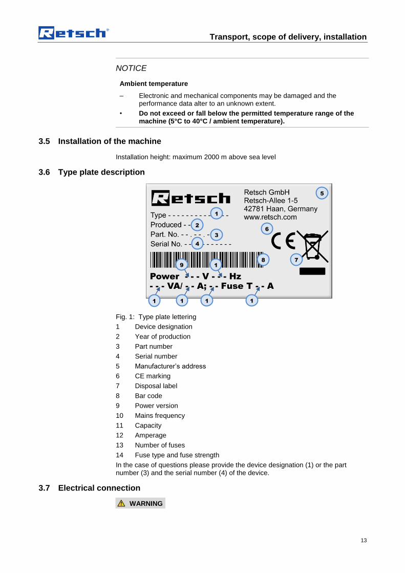
Fig. 1: Type plate lettering
1 Device designation
2 Year of production
3 Part number
4 Serial number
5 Manufacturer’s address
6 CE marking
7 Disposal label
8 Bar code
9 Power version
10 Mains frequency
11 Capacity
12 Amperage
13 Number of fuses
14 Fuse type and fuse strength
In the case of questions please provide the device designation (1) or the part number (3) and the serial number (4) of the device.
3.7 Electrical connection
WARNING
1
2
3
4
5
6
7 8
9 1
0
1
1
1
2
1
4
1
3
Transport, scope of delivery, installation
14
When connecting the power cable to the mains supply, use an external fusethat complies with the regulations applicable to the place of installation .
• Please check the type plate for details on the necessary voltage and frequency for the device.
• Make sure the levels agree with the existing mains power supply.
• Use the supplied connection cable to connect the device to the mains power supply.
• Make sure that the voltage and frequency of your mains connection corresponds to that on the type plate of the RS200.
– The mains connection must be fused to at least 16A
– An electrical connection without protective earth PE is not permitted.
The drive of the device is equipped with a frequency converter . In order to satisfy the EMC Directive , this is fitted with a mains filter and shielded cables to the motor. If your mains connection includes a residual current protection device, the suppressor capacitor wiring of the frequency converter when this is switched on (it is switched on by closing the grinding chamber hood) can lead to accidental triggering of the residual current protection device without any error being present on the device or in the mains installation.
In accordance with the state of the art, selective all current sensitive residual current protection devices are recommended for such cases. The tripping current must be sufficiently dimensioned because capacitive compensating current (shielded cable, mains filter) which only occurs for a short time can easily lead to accidental triggering.
In certain circumstances it may be necessary to operate the device without a residual current protection device. It is then necessary, however, to check that this does not contravene the local regulations of the electricity company or other institutions and the applicable standards.
3.8 Creating interface connection
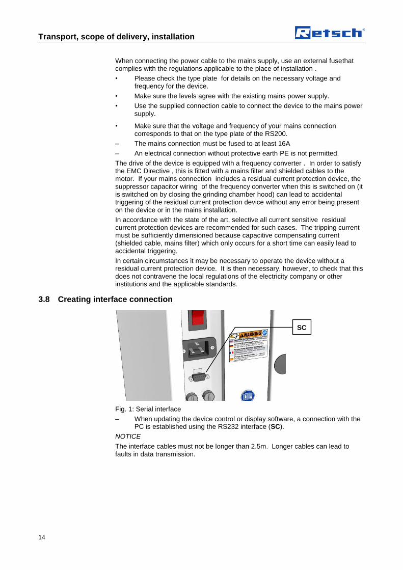
Fig. 1: Serial interface
– When updating the device control or display software, a connection with the PC is established using the RS232 interface (SC).
NOTICE
The interface cables must not be longer than 2.5m. Longer cables can lead to faults in data transmission.
SC

Transport, scope of delivery, installation
15
3.9 Transport
WARNING
Serious personal injury Falling loads
– The appliance is very heavy and can therefore cause serious personal injuries if it falls down.
• Lifting above head height is not permissible!
NOTICE
Transport
– Mechanical or electronic components may be damaged.
• The machine may not be knocked, shaken or thrown during transport.
NOTICE
Transport safeguard
– Components may be damaged.
• Operate the machine only without the transport safeguard or transport the machine only with transport safeguard.
Fig. 2: Unscrewing the transport lock from the transport pallet
The device is secured to the transport pallet by the transport lock and four nuts.
• Use a 13mm spanner to unscrew the four nuts.

Transport, scope of delivery, installation
16
Fig. 3: Removing the transport lock from the device
Four bolts secure the transport lock underneath the device.
• Use a 13mm spanner to unscrew the four bolts.
Fig. 4: Mounting the transport screws
The device should only be lifted and transported using the 4 transport screws (TS) provided. Net weight approx. 210 kg
TS
Transport, scope of delivery, installation
17
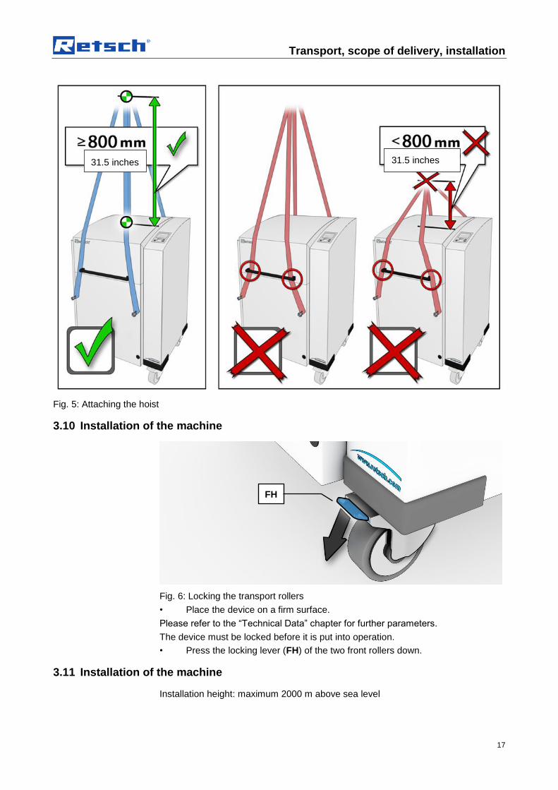
Fig. 5: Attaching the hoist
3.10 Installation of the machine
Fig. 6: Locking the transport rollers
• Place the device on a firm surface.
Please refer to the “Technical Data” chapter for further parameters.
The device must be locked before it is put into operation.
• Press the locking lever (FH) of the two front rollers down.
3.11 Installation of the machine
Installation height: maximum 2000 m above sea level
FH
31.5 inches 31.5 inches
Transport, scope of delivery, installation
18
NOTE
Installation
– Depending on the operating status of the mill, there may be slight vibrations.
• Place the mill on an even, flat and balanced supporting surface only. The supporting surface must be stable and must not vibrate.
NOTICE
Installation of the machine
– It must be possible to disconnet the machine from the mains at any time.
• Install the machine such that the connection for the mains cable is easily accessible.
Technical data
19
4 Technical data
4.1 Use of the machine for the intended purpose
CAUTION 1.V0004
Risk of explosion or fire Changing sample properties
– Consider that the properties and therefore also the hazardousness of your sample can change during the grinding process.
• Do not use any substances in this device which carry the risk of explosion or fire.
CAUTION
Risk of explosion or fire
– On account of its design, the device is not suitable for use in hazardous (potentially explosive) atmospheres.
• Do not operate the device in a hazardous atmosphere.
CAUTION
Danger of personal injury Dangerous nature of the sample
– Depending on the dangerous nature of your sample, take the necessary measures to rule out any danger to persons.
• Observe the safety guidelines and datasheets of your sample material.
Target group: Operating companies, operators
Machine type designation: PM400
Retsch ball mills are used to grind and mix soft, medium hard and extremely hard, brittle and fibrous materials. Dry and wet grinding are possible. Minerals, ores, alloys, chemicals, glass, ceramics, parts of plants, soil, sewage sludge, house or industrial waste and many other substances can be ground simply, quickly and without loss. The ball mills are used successfully in almost all areas of industry and research. This applies in particular where there are high demands in terms of hygiene, speed, fineness and reproducibility.
NOTICE
Area of use of the machine
– This machine is a laboratory machine designed for 8-hour single-shift operation.
• This machine may not be used as a production machine nor is it intended for continuous operation.
Technical data
20
4.2 Number of grinding stations
2 or 4 depending on the model
The grinding stations must be operated with the identical grinding jars and with the same weight during each grinding process.
NOTICE H0068
Strong vibration and loud noise Uneven load
– The device can produce very high levels of vibrations and noise when loading is uneven.
• Always use 2 or 4 grinding jars opposite each other.
• When using 2 grinding jars, the two free grinding stations must be secured using a clamping bolt and a lead frame.
• The grinding stations must be operated with the identical grinding jars and with the same weight during each grinding process.
• Switch the device off immediately if there are high levels of vibration and noise, and check the number and net weight of the jars.
4.3 Receptacle volume
Up to 4 times 300ml, depending on the grinding jar volume.
4.4 Feed size
Up to <10 mm, however this depends on the material.
4.5 Rated power
1500W
Make sure that the voltage and frequency of your mains connection correspond to that on the type plate of the device. The mains connection must be fused to at least 16A .
4.6 Electrical connection
WARNING
When connecting the power cable to the mains supply, use an external fusethat complies with the regulations applicable to the place of installation .
• Please check the type plate for details on the necessary voltage and frequency for the device.
• Make sure the levels agree with the existing mains power supply.
• Use the supplied connection cable to connect the device to the mains power supply.

Technical data
21
4.7 Emissions
CAUTION
Damage to hearing The level of noise can be high depending on the type of material, the knife used, the speed set and the duration of the grinding process.
- Noise that is excessive in terms of level and duration can cause impaired or permanently damaged hearing.
• Ensure suitable sound-proofing measures or wear hearing protection.
4.7.1 Noise levels
Noise measurement in accordance with DIN 45635-31-01-KL3
The noise levels are largely influenced by the machine speed, the grinding jar size and the diameter of the grinding balls used.
Workplace-related emissions LpAeq = up to 85dB(A)
4.7.2 Measurement conditions
Grinding set: 4x 500ml special steel with 5 balls each Ø30mm TC (tungsten carbide)
Sample material: quartz, 135g each
Speed: 380 min-1
4.8 Degree of protection
IP40
4.9 Protective equipment
This device is equipped with automatic lid closing which prevents it being started in an unsafe state.
– The device can only be started with closed lid.
– The lid can only be opened when the device has come to a halt.
4.10 Dimensions and weight
Height: up to approx. 1220 mm / Width: 836 mm / Depth:up to approx. 780 mm
Weight : PM400 net approx. 290 kg
4.11 Required floor space
Height (open cover): 1900mm / Width: 1400mm / Depth: 900mm;
NOTICE
A clearance distance of 100mm is necessary at the back to allow the fans to operate.

Operating the machine
22
5 Operating the machine
5.1 Views of the Instrument
Fig. 7: View of the front of the device
Fig. 8: Close-up of the grinding chamber
N
P
I
O
Q
N1
A
B
J
M
L
K
I
H
AK

Operating the machine
23
Fig. 9: View of the back of the device
S
T
U
V
W
X
Y

Operating the machine
24
5.2 Overview table of the parts of the device
Element Description Function
A Cover Closes the grinding chamber
B Damper for cover Secures the cover when it is open
H Clamping unit for grinding chamber Clamps grinding jar on the support
I Grinding jar Sample vessel
J Turntable Support for the grinding jar plate
K Pin closing mechanism Safety lock for the cover
L Control panel Device controller
M Closing mechanism Support for pin closing mechanism
N Handle for clamping unit (lead frame) Handle to clamp the grinding jars
N1 Locking sleeve Prevents the twist grip from being turned accidentally
O Safety Slider Safety component – checking whether the clamping unit is inserted and clamped
P Display window Displays the safety function
Q Latching bracket Supports the clamping unit
S Main switch Disconnects the device from the mains
T IEC socket Power supply for the power cable
U Serial interface Interface for communication with the device
V Support for safety fuse Access to the device fuse
W Type plate Description of device parameters
X Warning sign to pull out the plug Warning of electric shock
Y Sign with instruction to read the operating manual
Sign pointing out the need to read the operating manual

Operating the machine
25
5.3 Operating elements and displays
Fig. 10: View of the control panel
5.4 Overview Table of the Operating Elements and the Display
Element Description Function
F Control knob (rotary/push button) Rotary control to operate the device settings
G Button to open the cover Unlocks the cover
C Display Displays the control functions and parameters
D START button Starts grinding
E STOP button Stops grinding
5.5 Opening the device
The following steps are necessary in order to be able to use and clamp the grinding jar.
• Connect the device to the mains.
• Switch on the main switch at the back of the device.
• Press the button.
The safety lock opens and the lid can be lifted up
5.6 Closing the device
It is only possible to lock the grinding chamber if the device has been connected to the power supply and the main switch at the back of the device has been switched on.
• Shut the housing lid.
– A sensor detects the closing pin of the housing lid and the motorised lid closing mechanism is switched on.
– The housing lid is locked automatically.
G
C
D
E
F

Operating the machine
26
5.7 Emergency unlocking
CAUTION
Emergency Unlocking Drive continuing to run
– There is a substantial risk of injury if the drive and associated device parts run on a long time without being braked!
• Activate the emergency unlocking only when the machine has come to a complete stop and is disconnected from the power supply.
Fig. 11: Emergency release
A key is provided with device delivery. This can be used to open the device manually in the case of a power failure .
• Remove the cap (AK).
• Place the key (SN) in the opening (NR).
– To unlock the gear mechanism, it is necessary to push the key in further using a little force.
NR
AK
SN

Operating the machine
27
Fig. 12: Emergency release procedure
• At the same time as pushing the key (SN) in, rotate it in a clockwise direction as far as it will go.
– The lock is open and the lid can be lifted up.
5.8 Inserting the grinding jar
CAUTION V0049
Ejected objects Grinding jar not clamped
– Grinding jars or clamping mechanisms can be ejected. This results in a risk of injury.
• Never leave loose clamping devices without clamped grinding jars in the grinding jar support.
• Before starting the machine, ensure that all grinding jars are clamped.
• Ensure that the red sleeve of the clamping mechanism is clicked into place.
• In the case of extended grinding processes, check that the grinding jars are secure at the following intervals:
After 3 min, after 1h, after 5h then every 10-12h.
CAUTION
Scalding/burns Hot grinding jar
– Depending on the grinding process, the material being ground and accordingly the grinding jar can become very hot.
• Wear appropriate protection always when touching the grinding jar if it is hot.
NOTICE H0068
Strong vibration and loud noise Uneven load
– The device can produce very high levels of vibrations and noise when loading is uneven.
• Always use 2 or 4 grinding jars opposite each other.
• When using 2 grinding jars, the two free grinding stations must be secured using a clamping bolt and a lead frame.
• The grinding stations must be operated with the identical grinding jars and with the same weight during each grinding process.
• Switch the device off immediately if there are high levels of vibration and noise, and check the number and net weight of the jars.

Operating the machine
28
5.8.1 Clamping bolt
Fig. 13: Correct loading of the device – 4 or 2 grinding jars
Fig. 14: Incorrect loading of the device
Operating the machine
29
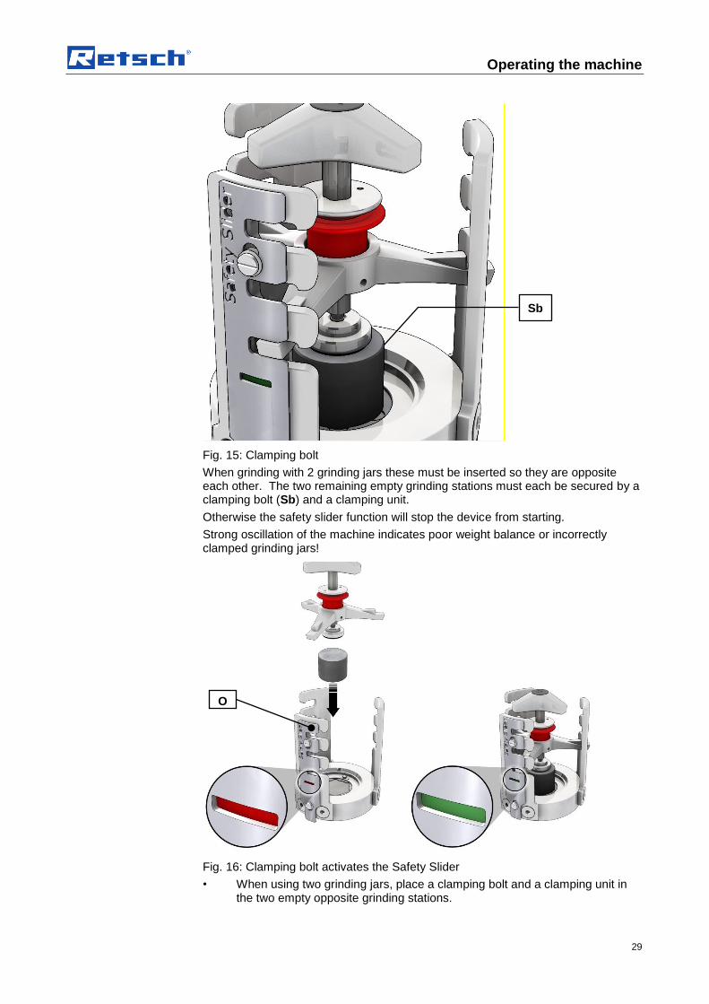
Fig. 15: Clamping bolt
When grinding with 2 grinding jars these must be inserted so they are opposite each other. The two remaining empty grinding stations must each be secured by a clamping bolt (Sb) and a clamping unit.
Otherwise the safety slider function will stop the device from starting.
Strong oscillation of the machine indicates poor weight balance or incorrectly clamped grinding jars!
Fig. 16: Clamping bolt activates the Safety Slider
• When using two grinding jars, place a clamping bolt and a clamping unit in the two empty opposite grinding stations.
Sb
O

Operating the machine
30
– The insertion and clamping of the clamping unit pushes the Safety Slider (O) upwards, thereby activating it.
After the machine has started, the device checks this safety function for approx. 15 seconds.
The device aborts the starting process and emits an error message if
– you have not clamped the clamping unit;
– you have not inserted any clamping unit or clamping bolts; or
– if the grinding jar is missing.
5.8.2 Inserting the grinding jar
Fig. 17: Clamping the grinding jar
• If necessary clean the grinding jar base (Mt) and the anti-rotation pin (Vs).
• Turn the grinding jar label (I) to the same side as the anti-rotation pin.
• Place the grinding jar in the grinding jar support.
– Pay attention to the anti-rotation device when using 250 and 500 ml grinding jars. The hole drilled in the bottom of the grinding jar to support the anti-rotation pin (Vs) is situated on the side of the lettering areas (I).
I
Vs
Mt

Operating the machine
31
5.8.3 Inserting the clamping unit
Fig. 18: Inserting the clamping unit
• Insert the clamping unit (H) in the three latching brackets (Q).
5.8.4 Function of the locking sleeve
Fig. 19: Function of the locking sleeve
• Pull the red sleeve (N1) upwards and clamp the grinding jar by twisting the three-star grip to the right.
• Allow the red sleeve (N1) to audibly click down into place, if necessary tightening slightly using the three-star grip.
• It should no longer be possible to turn the three-star grip.
– The locking sleeve now in the blocked position stops the threaded spindle from coming loose automatically.
H
Q
O
N1
open blocked

Operating the machine
32
5.9 Releasing the grinding jar clamping mechanism
Fig. 20: Releasing the grinding jar clamping mechanism
• Pull the red sleeve (5) upwards.
• Turn the three-star grip to the left to release the grinding jar.
• Keep turning the three-star grip to the left until the grinding jar clamping mechanism can be removed.
5.10 Opening the grinding jar clamping mechanism with a counter wrench
Fig. 21: Inserting the counter wrench
• The counter wrench (Ks) [accessory] can be used to loosen or tighten the clamping unit (H).
– When inserting the counter wrench (Ks), the locking sleeve (N1) is pushed upwards and released.
Ks
H
N1

Operating the machine
33
Fig. 22: Loosening the clamping unit
• Rest the counter wrench (Ks) on the latching bracket (Q) during closing and loosening.
5.11 Power failure during grinding
If the power fails during grinding, grinding will be interrupted. All parameters are retained, and the remaining grinding time is saved. When the device is switched on again, a corresponding message appears in the display.
You can continue the process by pressing the START button. The automatic saving of the remaining grinding time means the grinding then continues until the end of the originally set grinding time.
For safety reasons the device must be opened and the grinding chamber inspected. Grinding then continues automatically when the lid is closed.
The process is aborted by pressing the STOP button.
5.12 Mahlbehälterauswahl für unterschiedlichen Probenmaterialien
This device is only suitable for use with grinding jars from Retsch GmbH with a nominal volume of 12 ml - 500 ml.
They are available in the following materials:
• Agate
• Sintered corundum
• Zirconium oxide
• Stainless steel
• Special steel
• Tungsten carbide
5.13 Sample quantity
NOTICE
If the fill level in the grinding jar is too high or too low, this will impair the milling result and may cause damage (increased abrasion) to the grinding set.
Ks
Q

Operating the machine
34
5.13.1 Guides for material quantity and balls
Grinding jar volume
Sample volume
Max. feed size Ball filling (unit)
10mm 20mm 30mm 40mm
12 ml Up to 5 ml 1 mm 5 units - - -
25 ml Up to 10 ml 1 mm 8 units - - -
50 ml 5 – 20 ml 3 mm 10 units 3 units - -
80 ml 10 – 35 ml 4 mm 25 units 5 units - -
125 ml 15 – 50 ml 4 mm 30 units 7 units - -
250 ml 25 – 120 ml 6 mm 50 units 15 units 6 units -
500 ml 75 – 220 ml 10 mm 100 units 25 units 8 units 4 units
5.14 Ultrafine grinding
High degrees of fineness can frequently only be achieved using wet grinding.
Improved final fineness can be achieved in dry grinding by adding a few drops of stearin or acetic acid and by using grinding balls with a Ø<10mm and a fill level of 70-80% of the grinding jar volume.
5.15 Stacking the grinding jars
5.15.1 Stacking 50ml grinding jars
Fig. 23:
You can also stack two 50ml grinding jars on top of one another.
You will need the optional adapter to stack the grinding jars.
Stacking process:
• Place the grinding jar (M1) in the grinding jar base
• Place the adapter (A1) on the lid of M1
• Place grinding jar (M2) on the adapter
• Clamp the grinding jars as described in the chapter “Clamping the grinding jars”.
M2
A1
M1

Operating the machine
35
5.15.2 Stacking grinding jars smaller than 50ml
Fig. 24:
Grinding jars with a capacity of less than 50ml can be stacked on top of each other directly without the use of accessories.
Stacking process:
• Place the grinding jar (M2) directly on top of grinding jar (M1).
• Clamp the grinding jars as described in the chapter “Clamping the grinding jars”.
5.16 Handling grinding jars
5.16.1 Carrying and gripping
Fig. 25: Grinding jar
The gripping flanges (Gr) on the grinding jar lid permit secure handling.
5.16.2 Anti-rotation device
All 250ml and 500ml grinding jars have a drilled hole underneath the grinding jar as anti-rotation device. The anti-rotation device is only used with the PM400 and is located on the side of the grinding jar casing with lettering.
5.16.3 Heating the grinding jars
Depending on the grinding time and the fill level, the grinding jars can be heated to a temperature of up to 150°C during grinding.
This temperature change causes the pressure inside the grinding jar to increase. When unscrewing the lid, please note that this excess pressure is released by a sudden escape of air. This may be accompanied by particles of sample material.
Gr
Gr
M2
M1

Operating the machine
36
When grinding jars have been left to cool, a vacuum is created inside them which can make them difficult to open. The grinding jars can be prised open between the gripping flanges on the lid and the grinding jar, e.g. using a flat wooden stick (Hb).
5.17 Grinding jar – identification
All grinding jars can be identified by lettering which shows the article number and material.
5.18 Grinding jar cleaning
Fig. 26: Removing the O-ring
The O-ring (Or) on the groove (Nu) on the underneath of the lid can be lifted out easily to clean the grinding jar.
Grinding jars, including those with glued ceramic inserts, can be cleaned using alcohol, benzine or normal household detergents
NOTICE
When cleaning, do not expose grinding jars with ceramic inserts to sudden temperature differences.
Sudden temperature fluctuations can cause the ceramic inserts to crack.
5.18.1 Drying the grinding jars
After cleaning, the grinding jars can be dried in the drier cabinet at the temperatures specified below.
Grinding jar material Temperature
Special steel Up to 200°C
Or
Nu
Hb

Operating the machine
37
Stainless steel Up to 200°C
Tungsten carbide (TC) Up to 150°C
Sintered corundum Up to 120°C
Agate Up to 120°C
Zirconium oxide Up to 120°C
Silicon nitride Up to 120°C
5.19 Closing the grinding jar
After filling the grinding jars, they should be closed using the locking mechanisms available as an accessory.
Fig. 27: Locking mechanism
In the case of grinding jars with material inserts made of ceramics or TC, only use locking mechanisms that support the material insert in the grinding jar lid. This is essential due to the expected internal pressure.
NOTICE
During wet grinding in grinding jars with material inserts, do not use the older locking mechanisms. Older locking mechanisms only clamp the gripping flanges of the grinding jars, which means that the material inserts may be pushed out if internal pressure arises.
Use of agate grinding jars for wet grinding with solvents should in particular be reconsidered because of the internal pressure that arises and the inhomogeneous material properties of a natural product.
Tighten the clamping screws on the locking mechanism to 2.5 Nm. Only with this initial tension are internal pressures of up to 5 bar permissible.
NOTICE
Damage to the grinding jar lid and the device
The three screws on the safety clip of the aeration cover may become loose and damage the inside of the device.
After tightening the safety clamping device, check that the three screws on the safety clip are still screwed tight.
Please note that the grinding jars may heat up to over 100°C depending on the grinding jar size, the ball filling, the speed and the grinding time.

Operating the machine
38
The PM400 is fitted with a fan which extracts the waste heat created during grinding directly out of the grinding chamber. The extraction volume per hour is greater than 20 times the grinding chamber volume. The fan has standstill monitoring with signalling.
The airflow from the fan during grinding can be discharged into an extractor hood if necessary.
Check that the locking mechanism is secure before removing the grinding jar.
Only remove grinding jars with locking mechanism, and only open after cooling when in a safe position (extraction device).

Display and operation
39
6 Display and operation
6.1 Symbols in the Display Unit
Fig. 28: View of the menu on the display unit
Element Description Function
C1 Menu navigation Switching between manual operating mode, program and basic settings
C2 Specification of grinding parameters
Displaying and setting grinding parameters
C3 Icons for device functions Displaying the function statuses of sound, automatic opening and grinding jar recognition
C4 Icon for scrolling direction Displays the possible scrolling directions
C5 Grinding parameters Display of values
Automatic opening switched on
Automatic opening switched off
Direction reversal switched on
Direction reversal switched off
Motor or frequency converter too hot
Power Grinding output display
Acoustic warning signal on
Acoustic warning signal off
Scrolling upwards or downwards possible
Only scrolling upwards possible
C4
C1
C5
C2
C3
Display and operation
40
Only scrolling downwards possible
6.2 Display unit – operation of the device
This device offers a new, very convenient user inteface. All relevant data can be entered and retrieved using a graphics display with one-button operation. The menu is available in different languages.
6.2.1 Adjustment options using the display menu
The selection bar in the display should be operated as follows:
Rotating function I)
• Rotate the operating button to get to the different menu items. The selected menu items are marked by the dark selection bar. Areas that cannot be changed are skipped.
Rotating function II)
• Rotate the operating button to change numerical values and decisions in the menu items.
Press I)
• Press the operating button to open selected menu items.
Press II)
• Press the operating button to confirm settings.
Press III)
• Keeping the operating button pressed for longer takes you back to the basic screen (Level 1).
6.2.2 Navigating between operating modes
• Rotate the operating button in a clockwise direction until the dark line cursor is in the navigation menu (C1).
• Press the operating button (F).
– The icon for the scrolling direction (C4) changes from
to .
• By pressing the operating button, navigate between manual operation, Programs 01 to 10 and the basic settings operating modes.
• Press the operating button (F) to activate the selected operating mode.
– The icon for the scrolling direction (C4) changes from
to .
• By rotating the operating button, switch to the sub-items of the selected menu item.
6.3 Direct access to the language menu
If you have unintentionally set the wrong language, you can go straight to the language menu by following the steps below.

Display and operation
41
• Switch the device off at the main switch.
• Switch the device on while simultaneously pressing the buttons START - STOP – Open hood.
• After selecting the correct language, switch the device off and then immediately back on.
• Confirm your selection by pressing the operating button.
The device is now set permanently to your language and you are in the main menu.

Display and operation
42
6.4 Menu structure
Complete summary of all menu options:
MANUAL OPERATING MODE
Grinding time
Speed
Interval
Direction reversal
Pause time
Save parameters
Program
Save
Back
Start in
Start in:
Screen notice: To cancel press STOP
Back
PROGRAM [01 - 10]
Grinding time
Speed
Change program
Program
Grinding time
Speed
Save
Back
Delete program
Program
Delete
Back
BASIC SETTINGS
Automatic opening
Language
Brightness
Date
Time
Acoustic signal
Service
Operating hours
Software version of display
Software version of controller
Update software
Display
Software update starts automatically
Controller
Software update starts automatically
Back
Back
6.5 Operating modes
You can select the following operating modes using the menu navigation (C1):
6.5.1 Manual operation
When this function has been set you can access and change all parameters and functions at any time. This is also possible during grinding.
6.5.2 Program 01 to 10
In programs 01 to 10 the previously set parameters for grinding time and speed can be saved to a memory.
6.5.3 Basic settings
You can adjust the following device settings in this settings menu:
Display and operation
43
– Automatic opening
– Language
– Brightness
– Date
– Time
– Acoustic warning signal
– Service
6.6 Manual operation
6.6.1 Grinding time
00:01:59 to 99:59:59 (hours : minutes : seconds)
The device is started with the preselected grinding time and at the last speed used. Direction reversal with pause time has not been switched on
6.6.2 Speed
30 to 400 rpm
The device is started with the preselected grinding time and at the last speed used. Direction reversal with pause time has not been switched on
6.6.3 Interval
00:00:01 to 99:59:59 (hours : minutes : seconds)
The interval time can be set here according to the grinding time. If no interval has been set, no direction reversal can be set.
6.6.4 Direction reversal
On/off
The device is started with the preselected grinding time, speed and direction reversal. The machine rotates in one direction for the set interval time, comes to a halt and starts again immediately in the other direction without a pause time.
6.6.5 Pause time
00:00:01 to 99:59:59 (hours : minutes : seconds)
The pause time between intervals can be set here.
No pause time can be set if no interval has been set.
The device is started with the preselected grinding time, speed and direction reversal. The machine rotates in one direction for the set interval time and comes to a halt; once it has stopped at the set interval time, the previously set pause time is displayed and counts down to 00:00:00.
The device starts again in the other direction when the pause time has expired.
6.6.6 Save parameters
The previously set parameters such as grinding time and speed can be saved in a memory here.
• Set the desired parameters.
• By turning the control knob (F), switch to the Save parameters menu option.
• Press the control knob (F).
– The Save parameters menu opens and the dark cursor line is on Program.
• Press the control knob (F) to select a program memory location.
• By turning the control knob (F), switch to the desired memory location.
• Press the control knob (F) to exit the memory location selection.
• Select either

Display and operation
44
- Save to save settings or
- Back to cancel without saving.
6.6.7 Start in
00:00:01 to 99:59:59 (hours : minutes : seconds)
You can set a countdown for starting the device.
• Press the STOP button to cancel the countdown.
6.7 Programs
6.7.1 Change program
You can change the saved parameters for any program in this menu.
• By turning the control knob (F), switch to the Change program menu option.
• Press the control knob (F).
– The Save parameters menu opens and the dark cursor line is on Program.
NOTICE You can change the active program or any other program.
• Press the control knob (F) to activate the program selection.
• By turning the control knob (F), switch to the desired memory location.
• Press the control knob (F) to exit the memory location selection.
• Adjust the desired grinding parameters.
• Finally select either
- Save to save settings or
- Back to cancel without saving.
– This takes you back to the Program level.
NOTICE It is not possible to start a program that has not been saved.
6.7.2 Delete program
You can delete the saved parameters for any program in this menu
NOTICE
Only the saved parameters for the program concerned are deleted. The program memory location continues to exist.
• By turning the control knob (F), switch to the Delete program menu option.
• Press the control knob (F).
– The Delete program menu opens and the dark cursor line is on Program.
• Press the control knob (F) to activate the program selection.
• By turning the control knob (F), switch to the desired program.
• Press the control knob (F) to exit the program selection.
• Finally select either
- Delete to delete the settings or
- Back to cancel without deleting.
– This takes you back to the Program level.
6.8 Basic settings
NOTICE
It is not possible to begin grinding while the basic settings menu is active.

Display and operation
45
6.8.1 Automatic opening
In this menu you can set whether the grinding jar lid opens automatically when grinding ends or only when the button is pressed.
If the function is switched off, the following pictogram appears on the display as confirmation.
Fig. 29: Automatic opening pictogram
6.8.2 Language
You can select the menu language here. After selecting and pressing the control knob, the entire menu structure is displayed in your language.
NOTICE
The language menu is displayed when the device is switched on for the first time.
• Select the desired language by turning the control knob. – Press to confirm the selection; “open lid” appears on the display.
6.8.3 Brightness
The brightness can be adjusted to suit the respective user or environment (sunshine, glare etc.).
6.8.4 Date
The current date can be entered here.
The device can be disconnected from the mains for up to 30 days before the settings are lost.
6.8.5 Time
The time can be entered here.
The time then appears in the stand-by monitor.
The device can be disconnected from the mains for up to 30 days before the settings are lost.
6.8.6 Acoustic warning signal
Error messages indicating incorrect operation can be supported by an acoustic warning signal. The corresponding pictogram appears if the function has been switched off
6.8.7 Service
6.8.7.1 Operating hours
Grinding hours are counted, i.e. the total times between START and STOP. It is not possible to manipulate the times.
6.8.7.2 Software version of display
Shows the software version of the display.
6.8.7.3 Software version of the controller
Shows the version of the operating software .
6.8.7.4 Update software
6.8.7.4.1 Display
– The target display unit is selected on the PC using a selection menu for updating software.

Display and operation
46
– The data are transmitted from the connected PC to the controller circuit board using an interface cable (RS232). The controller circuit board forwards the data to the boot loader of the display unit.
6.8.7.4.2 Controller
– The target device controller is selected on the PC using a selection menu for updating software.
– The data are transmitted from the connected PC to the controller circuit board using an interface cable (RS232). The controller circuit board forwards the data to the boot loader of the device controller.
6.8.8 Safety notice
For many years the grinding jar clamping mechanism has been a proven, easy to use and reliable device. The basic prerequisite both for the safety of the operator and for the life of the machine components is careful clamping of the grinding jars.
Please remember that this device involves grinding equipment which applies very high amounts of energy into the sample material, and that the grinding set therefore needs to be locked into position carefully.
Correct securing of the grinding jar is always queried prior to starting the machine in order to prevent operating errors.
Employees who have been especially trained and who are familiar with operation of the PM can also permanently fade out this safety notice. We do not recommend this course of action, particularly when there are changes in operating staff!
The device software is set up such that the message about the need to confirm clamping of the grinding jars is always displayed when the start button is actuated prior to starting the machine.
The grinding process begins after confirmation.
This safety notice can be faded out in the “Settings” menu.

Fault messages
47
7 Fault messages
Error code (FEHLER) BESCHREIBUNG DEFECT DESCRIPTION TRANSLATION
E10 ANTRIEB ÜBERLASTET DRIVE OVERLOAD
E11 FEHLER ANTRIEB/MOTOR FAILURE DRIVE/MOTOR
E20 FEHLER STEUERUNG FAILURE CONTROLLER
E23 FEHELR LÜFTER FAILURE FAN
E26 FEHLER FREQUENZUMRICHTER FAILURE FREQUENCY CONVERTER
E41 FEHLER DREHZAHLSENSOR FAILURE SPEED SENSOR
E50 FEHLER SICHERHEITSKREIS FAILURE IN SAFETY CIRCUIT
H10 ANTRIEB ABKÜHLEN LASSEN! ALLOW DRIVE TO COOL DOWN
H13 BELASTUNGSGRENZE! DREHZAHL REDUZIEREN! OVERLOAD! REDUCE SPEED!
H14 BELASTUNGSGRENZE ÜBERSCHRITTEN! DREHZAHL
WURDE REDUZIERT! OVERLOAD! SPEED HAS BEEN REDUCED!
H42 DECKEL/HAUBE ÖFFNEN UND SCHLIESSEN OPEN AND CLOSE LID/COVER

Cleaning, wear and service
48
8 Cleaning, wear and service
WARNING
Risk of a fatal electric shock
- An electric shock can cause injuries in the form of burns and cardiac arrhythmia, respiratory arrest or cardiac arrest.
• Do not clean the blender under running water. Use only a cloth dampened with water.
• Disconnect the power supply plug before cleaning the blender.
WARNING W0012
The device must always be switched off and disconnected from the mains before any interventions for cleaning or servicing purposes.
8.1 Service
Fig. 30: Closing pin maintenance
The following maintenance work should be carried out at regular intervals, and at least monthly to guarantee the operational safety of the device:
• Check roller (1) of the closing pin for free movement, and oil where necessary, e.g. using sewing machine oil.
• Clean the magnets (2) on the closing pin.
Cleaning, wear and service
49
8.1.1 Servicing the clamping unit
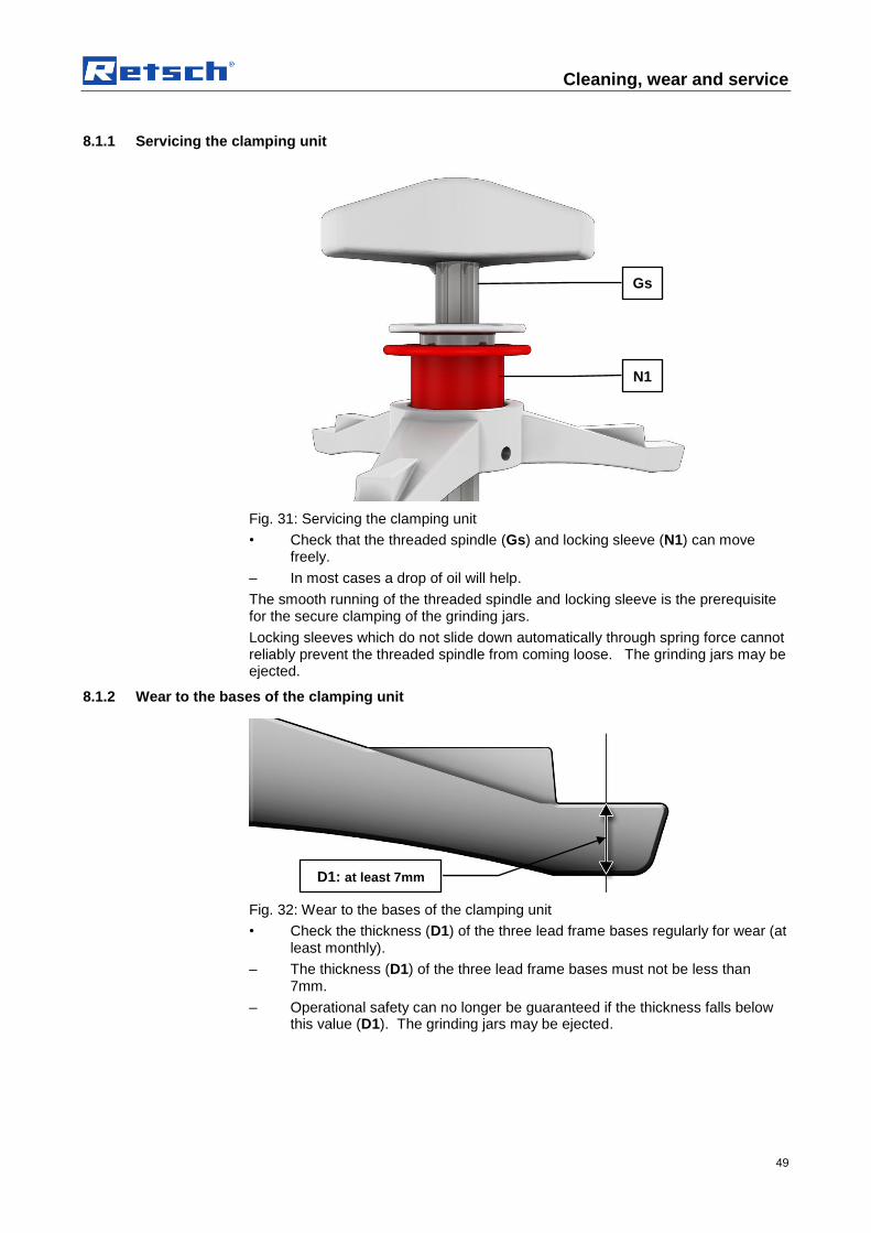
Fig. 31: Servicing the clamping unit
• Check that the threaded spindle (Gs) and locking sleeve (N1) can move freely.
– In most cases a drop of oil will help.
The smooth running of the threaded spindle and locking sleeve is the prerequisite for the secure clamping of the grinding jars.
Locking sleeves which do not slide down automatically through spring force cannot reliably prevent the threaded spindle from coming loose. The grinding jars may be ejected.
8.1.2 Wear to the bases of the clamping unit
Fig. 32: Wear to the bases of the clamping unit
• Check the thickness (D1) of the three lead frame bases regularly for wear (at least monthly).
– The thickness (D1) of the three lead frame bases must not be less than 7mm.
– Operational safety can no longer be guaranteed if the thickness falls below this value (D1). The grinding jars may be ejected.
Gs
N1
D1: at least 7mm

Cleaning, wear and service
50
8.1.3 Rubber washer on the pressure plate
Fig. 33: Rubber washer on the pressure plate
• Check the O-ring (Or) on the pressure plate regularly for wear and to ensure it is secure.
8.1.4 Wear to latching bracket
Fig. 34: Wear to the latching bracket
• Check the thickness (H1) of the twelve latching brackets (Q) regularly for wear (at least monthly).
– The thickness (H1) of the twelve latching brackets (Q) must not be less than 15mm.
– Operational safety can no longer be guaranteed if the thickness falls below this value (H1). The grinding jars may be ejected.
8.2 Replacing the machine fuses
WARNING W00014
Mortal danger from electric shock Exposed power contacts
– When replacing fuses on the cutout or fuse adapter you may come into contact with live contacts. An electric shock can lead to burns and to cardiac arrhythmias or to respiratory arrest and cardiac arrest.
Or
H1: at least 15mm

Cleaning, wear and service
51
• Remove the mains cable before replacing fuses.
Fig. 35: Changing the fuses
NOTICE
Always replace all 4 fuses (TB).
– Type of fuse: 4 x 200mA T 250V
• Unscrew the 4 fuse holders (TC).
• Remove the fuse from the fuse holders and insert the new fuses.
• Place the fuse holders with the inserted fuses in the openings (TA).
8.3 Returning for service and maintenance
Fig. 2: Returned goods dispatch note
TC
TB
TA

Cleaning, wear and service
52
RETSCH devices and accessories can only be accepted for repair, maintenance or calibration if the returned goods despatch note has been correctly completed in full.
• When returning a device, attach the returned goods dispatch note to the outside of the packaging.
In order to eliminate any health risk to our employees, we reserve the right to refuse acceptance and to return the respective delivery at the expense of the sender.

Disposal
53
9 Disposal
Please observe the respective statutory requirements with respect to disposal.
Information on disposal of electrical and electronic machines in the European Community.
Within the European Community the disposal of electrically operated devices is regulated by national provisions that are based on the EU Directive 2002/96/EC on Waste Electrical and Electronic Equipment (WEEE).
Accordingly, all machines supplied after 13.08.2005 in the business-to-business area to which this product is classified, may no longer be disposed of with municipal or household waste. To document this they have the following label:
Fig. 3: Disposal label
Since the disposal regulations within the EU may differ from country to country we would request you to consult your supplier.

54
10 Index
>
>Mains connection 14
1
16A 20
A
Acoustic warning signal 45 Adjustment options using the display menu 40 Agate 33 all current sensitive 14 all current sensitive 14 Ambient temperature 12 Amperage 13 Anti-rotation device 35 Automatic lid closing 21 Automatic opening 45
B
Ball quantity 33 size 33
Ball filling 33 Bar code 13 Basic settings 42, 44 Brightness 45
C
Capacity 13 CE marking 13 Change program 44 Changes 7 Clamping bolt 28 Clamping mechanism
opening 32 releasing 32
Clamping unit servicing 49 wear 49
Cleaning the grinding jars 36 Cleaning, wear and service 48 Clearance distance 21 Close-up of the grinding chamber 22 Closing pin 25 Closing the grinding jar 37 Conditions for the place of installation 12 Confirmation 11 Connection cable 14, 20 Controller 46 Copyright 7 counter wrench 32 Counter wrench 32 creating interface connection 14
D
Date 45 Degree of protection 21 Delete program 44 Depth 21 Description 24, 25, 39 Device
closing 25 open 25
Device designation 13 Dimensions and weight 21 DIN 45635-31-01-KL3 21 Direct access to the language menu 40 Direction reversal 43 Display 45 Display and operation 39 Display unit – operation of the device 40 Disposal 53 Disposal label 13 Disposal label 53
E
Electrical connection 13, 20 EMC Directive 14 Emergency release 26 Emergency unlocking 26 Emissions 21 Emissions 21 Error code 47 Error messages 47 Errors 47 Explanations of the safety warnings 8 External fuse 14, 20
F
Fault messages 47 feed size 20 Feed sizes 33 Frequency converter 14 Function 24, 25, 39 Function of the locking sleeve 31 Fuse strength 13 Fuse type 13
G
General safety instructions 9 Grinding chamber inspection 33 Grinding jar – identification 36 Grinding jar cleaning 36 Grinding jar volume 33 Grinding time 43
H
Handling grinding jars 35 Height 21

55
Hoist attaching 17
I
Inserting the clamping unit 31 Inserting the grinding jar 27, 30 Installation height 13, 17 Installation of the machine 13, 17 Interval 43 IP40 21
L
Latching bracket wear 50
Lid closing 21 Lid closing mechanism 25 Locking sleeve 32 Locking the transport rollers 17 LpAeq 21
M
Machine type designation 19 Mahlbehälter Auswahl 33 Mains frequency 13 Manual operation 42 Manual operation 43 Manufacturer’s address 13 Measurement conditions 21 Measurement of noise levels 21 Menu structure 42 Messages
errors 47 Moderate or mild injury 8 Mounting the transport screws 16
N
Noise levels 21 Nominal volume 33 Notes on the Operating Manual 7 Number of fuses 13 Number of grinding stations 20
O
Operating elements and displays 25 Operating hours 45 Operating modes 42 Operating software version 45 Operating the machine 22 Operation 39 Overview Table of the Operating Elements and
the Display 25 Overview table of the parts of the device 24
P
Packaging 12 Part number 13 Pause time 43 Power 33 Power failure 26, 33
Power failure during grinding 33 Power version 13 Pressure plate 50 Probenmaterialien 33 Program 01 to 10 42 Programs 44 property damage 8 Protective earth 14 Protective equipment 21
Q
Quantity ball 33
R
Rated power 20 Receptacle volume 20 Regulations for the place of installation 14, 20 Releasing the grinding jar clamping mechanism
32 Remaining grinding time 33 Removing the O-ring 36 Repairs 10 Replacing the machine fuses 50 Required floor space 21 Residual current protection device 14 Return goods dispatch note 51 Returning for service and maintenance 51 RS232 46 Rubber washer 50
S
Safety notice 46 Safety warnings 8 Sample quantity 33 Sample volumes 33 Save parameters 43 Selection bar 40 Serial number 13 serious injury 8 Service 45 Service 48 Service Address 10 Set language 45 shielded cable 14 Sintered corundum 33 Software
update 45 Software version of controller 45 Software version of display 45 Special steel 33 Speed 43 Stacking the grinding jars 34 Stainless steel 33 Start in 44 Suppressor capacitor wiring 14 Symbols in the Display Unit 39

56
T
Target group 19 Target group 9 Technical data 19 Temperature fluctuation and condensed water 12 Time 45 Transport 12, 15 Transport lock
removing from the device 16 Transport, scope of delivery, installation 12 Tripping current 14 Tungsten carbide 33 Type plate 14, 20 type plate description 13 Type plate lettering 13
U
Ultrafine grinding 34 Unscrewing the transport lock from the transport
pallet 16
Use of the machine for the intended purpose 19
V
View of the back of the device 23 View of the control panel 25 View of the front of the device 22 View of the menu on the display unit 39 Views of the Instrument 22
W
Weight 21 Width 21 Workplace-related emissions 21 wrong language 40
Y
Year of production 13
Z
Zirconium oxide 33
Authorized person for the compilation of technical documents: J. Bunke (technical documentation)
The following records are held by Retsch GmbH in the form of Technical Documentation:
Detailed records of engineering development, construction plans, study (analysis) of the measures required for conformity assurance, analysis of the residual risks involved and operating instructions in due form according to the approved regulations for preparation of user information data.
The CE-conformity of the Retsch Planetary Ball Mill Type PM 400 is assured herewith. In case of a modification to the machine not previously agreed with us as well as the use of not licensed spare parts and accessories this certificate will lose its validity. Retsch GmbH Haan, January 2010 Dr. Stefan Mähler Manager technical services
R e t s c h G m bH R e ts c h - Al l e e 1 - 5 4 2 7 81 H a a n G e r m a n y w w w . r e t s ch . c om
PLANETARY BALL MILL PM 400
FB
-EW
-805-0
54 (
E)
Änderu
ngssta
nd
C 01.2
012
CERTIFICATE OF CE-CONFORMITY Translation
Certificate of CE-Conformity according to: EC Mechanical Engineering Directive 2006/42/EC Applied harmonized standards, in particular: DIN EN ISO 12100 Security of machines EC Directive Electromagnetic Compatibility 2004/108/EC Applied standards, in particular: EN 61000-3-2/-3 Electromagnetic compatibility (EMC) EN 61236 Electrical measuring, operating, controlling and laboratory equipment –
EMC-requirements in conjunction with EN 61000 EN 55011 Limit values and measuring procedures for noise suppression of industrial,
scientific and medical high frequency devices Additional applied standards, in particular DIN EN 61010 Safety prescriptions concerning measuring-, operating-, controlling- and
laboratory equipment


Copyright ® Copyright by Retsch GmbH Haan, Retsch-Allee 1-5 D-42781 Haan Federal Republic of Germany


