28
Manual These instructions are to be left with the user POWER SHOWER MANUAL Installation and User Guide
1
Manual
These instructions are to be left with the user
POWER SHOWERMANUAL
Installation and User Guide
2
CONTENTSIntroduction .............................................................................................3
Patents .................................................................................................3Important Safety Information .................................................................4
Warning! ...............................................................................................4Caution! ................................................................................................6
Pack Contents .........................................................................................7Dimensions ..............................................................................................8Specifications ..........................................................................................9Installation Requirements ....................................................................10Installation ............................................................................................. 11
General ............................................................................................... 11Electrical ............................................................................................. 11Plumbing ............................................................................................12
Commissioning .....................................................................................19Operation ...............................................................................................20Fault Diagnosis ......................................................................................21
Fault Diagnosis - User Maintenance ..................................................21Fault Diagnosis - Installer Maintenance .............................................22
Maintenance ...........................................................................................24Cleaning .............................................................................................24Handset ..............................................................................................24
Spare Parts ............................................................................................25Accessories ...........................................................................................26Notes ......................................................................................................27Customer Service ..................................................................................28
3
The Mira Vigour Manual Power Shower is an all-in-one power shower with an integral mains voltage pump, and separate controls for flow and temperature. It features a 15 mm dual entry push-fit manifold which supports various inlet supply configurations. The manifold includes inlet filters and check valves.Designed to be surface mounted, the Mira Vigour Manual Power Shower comes complete with an adjustable spray handset with three settings, flexible hose, adjustable slider, sliding rail, soap tray and bracket.
INTRODUCTION
GuaranteeFor domestic installations, Mira Showers guarantee the Mira Vigour against any defect in materials or workmanship for a period of one year from the date of purchase (shower fittings for one year).For non-domestic installations, Mira Showers guarantee the Mira Vigour against any defect in materials or workmanship for a period of one year from the date of purchase.For terms and conditions refer to the back cover of this guide.
PatentsPatents GB: 2 340 210
If you experience any difficulty with the installation or operation of your new Power Shower, please refer to ‘Fault Diagnosis’, before contacting Kohler Mira Ltd. Our telephone and fax numbers can be found in the back of this guide.
Application Power Shower Power Shower withFittings
Domestic
Light Commercial
Heavy Commercial
Recommended Usage
4
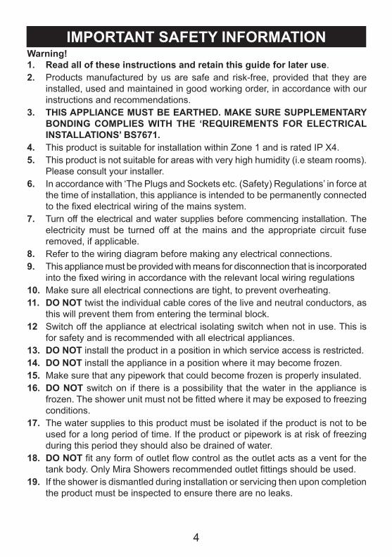
IMPORTANT SAFETY INFORMATIONWarning!1. Read all of these instructions and retain this guide for later use.2. Products manufactured by us are safe and risk-free, provided that they are
installed, used and maintained in good working order, in accordance with our instructions and recommendations.
3. THIS APPLIANCE MUST BE EARTHED. MAKE SURE SUPPLEMENTARY BONDING COMPLIES WITH THE ‘REQUIREMENTS FOR ELECTRICAL INSTALLATIONS’ BS7671.
4. This product is suitable for installation within Zone 1 and is rated IP X4.5. This product is not suitable for areas with very high humidity (i.e steam rooms).
Please consult your installer.6. In accordance with ‘The Plugs and Sockets etc. (Safety) Regulations’ in force at
the time of installation, this appliance is intended to be permanently connected to the fixed electrical wiring of the mains system.
7. Turn off the electrical and water supplies before commencing installation. The electricity must be turned off at the mains and the appropriate circuit fuse removed, if applicable.
8. Refer to the wiring diagram before making any electrical connections.9. This appliance must be provided with means for disconnection that is incorporated
into the fixed wiring in accordance with the relevant local wiring regulations10. Make sure all electrical connections are tight, to prevent overheating.11. DO NOT twist the individual cable cores of the live and neutral conductors, as
this will prevent them from entering the terminal block.12 Switch off the appliance at electrical isolating switch when not in use. This is
for safety and is recommended with all electrical appliances.13. DO NOT install the product in a position in which service access is restricted.14. DO NOT install the appliance in a position where it may become frozen. 15. Make sure that any pipework that could become frozen is properly insulated.16. DO NOT switch on if there is a possibility that the water in the appliance is
frozen. The shower unit must not be fitted where it may be exposed to freezing conditions.
17. The water supplies to this product must be isolated if the product is not to be used for a long period of time. If the product or pipework is at risk of freezing during this period they should also be drained of water.
18. DO NOT fit any form of outlet flow control as the outlet acts as a vent for the tank body. Only Mira Showers recommended outlet fittings should be used.
19. If the shower is dismantled during installation or servicing then upon completion the product must be inspected to ensure there are no leaks.
5
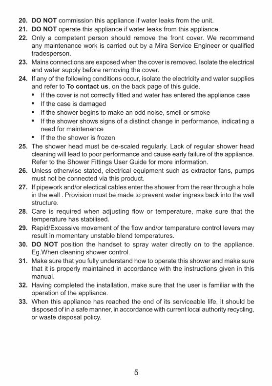
20. DO NOT commission this appliance if water leaks from the unit.21. DO NOT operate this appliance if water leaks from this appliance.22. Only a competent person should remove the front cover. We recommend
any maintenance work is carried out by a Mira Service Engineer or qualified tradesperson.
23. Mains connections are exposed when the cover is removed. Isolate the electrical and water supply before removing the cover.
24. If any of the following conditions occur, isolate the electricity and water supplies and refer to To contact us, on the back page of this guide.• If the cover is not correctly fitted and water has entered the appliance case• If the case is damaged• If the shower begins to make an odd noise, smell or smoke• If the shower shows signs of a distinct change in performance, indicating a
need for maintenance• If the the shower is frozen
25. The shower head must be de-scaled regularly. Lack of regular shower head cleaning will lead to poor performance and cause early failure of the appliance. Refer to the Shower Fittings User Guide for more information.
26. Unless otherwise stated, electrical equipment such as extractor fans, pumps must not be connected via this product.
27. If pipework and/or electical cables enter the shower from the rear through a hole in the wall . Provision must be made to prevent water ingress back into the wall structure.
28. Care is required when adjusting flow or temperature, make sure that the temperature has stabilised.
29. Rapid/Excessive movement of the flow and/or temperature control levers may result in momentary unstable blend temperatures.
30. DO NOT position the handset to spray water directly on to the appliance. Eg.When cleaning shower control.
31. Make sure that you fully understand how to operate this shower and make sure that it is properly maintained in accordance with the instructions given in this manual.
32. Having completed the installation, make sure that the user is familiar with the operation of the appliance.
33. When this appliance has reached the end of its serviceable life, it should be disposed of in a safe manner, in accordance with current local authority recycling, or waste disposal policy.
6
Caution!1. Read all of these instructions and retain this guide for later use.2. Make sure that this guide is left with the user. Pass on this guide in the event
of change of ownership of the installation site.3. Follow all warnings, cautions and instructions contained in this guide, and on
or inside the shower.4. Installation must be carried out in accordance with these instructions, and must
be conducted by designated, qualified and competent personnel.5. The electrical installation must comply to ‘BS 7691 Requirements for Electrical
Installations’ (commonly referred to as the IEE Wiring Regulations Part 7, or any particular regulations and practices, specified by the local electricity supply company) in force at the time of installation. The installation should be carried out by an electrician or contractor who is registered, or is a member of, an association such as:• National Inspection Council for Electrical Installation and Contracting
(NICEIC), throughout the UK• The Electrical Contractors Association (ECA), England and Wales• The Electrical Contractors Association of Scotland (ECAS)
6. The plumbing installation must comply with the requirements of UK Water Regulations/Bye-laws (Scotland), Building Regulations or any particular regulations and practices, specified by the local water company or water undertakers. The installation should be carried out by a plumber or contractor who is registered, or is a member of, an association such as:• Institute of Plumbing (IOP), throughout the UK• National Association of Plumbing, Heating and Mechanical Services
Contractors (NAPH & MSC), England and Wales• Scottish and Northern Ireland Plumbing Employers’ Federation (SNIPEF),
Scotland and Northern Ireland7. This appliance is not thermostatic and can produce scalding temperatures if not
operated in accordance with the instructions given in this manual.
8. This appliance is not intended for use by persons (including children) with reduced physical, sensory or mental capabilities, or lack of experience and knowledge, unless they have been given supervision or instruction concerning the use of the appliance by a person responsible for their safety.
9. Children should be supervised to make sure that they do not play with the appliance.
10. Sunburn or skin conditions can increase your sensitivity to hot water.
7
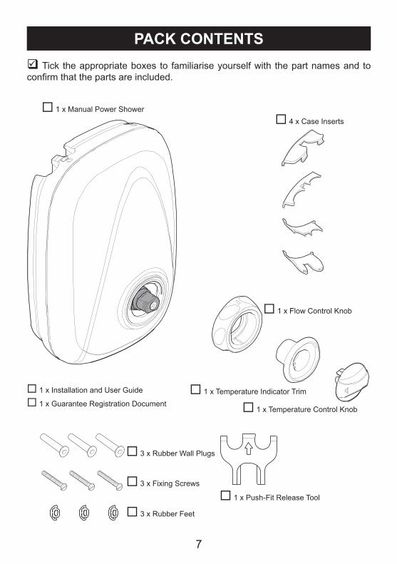
PACK CONTENTS Tick the appropriate boxes to familiarise yourself with the part names and to confirm that the parts are included.
1 x Manual Power Shower 4 x Case Inserts
1 x Flow Control Knob
1 x Temperature Control Knob
1 x Temperature Indicator Trim
1 x Push-Fit Release Tool
3 x Rubber Wall Plugs
3 x Rubber Feet
3 x Fixing Screws
1 x Installation and User Guide
1 x Guarantee Registration Document
8
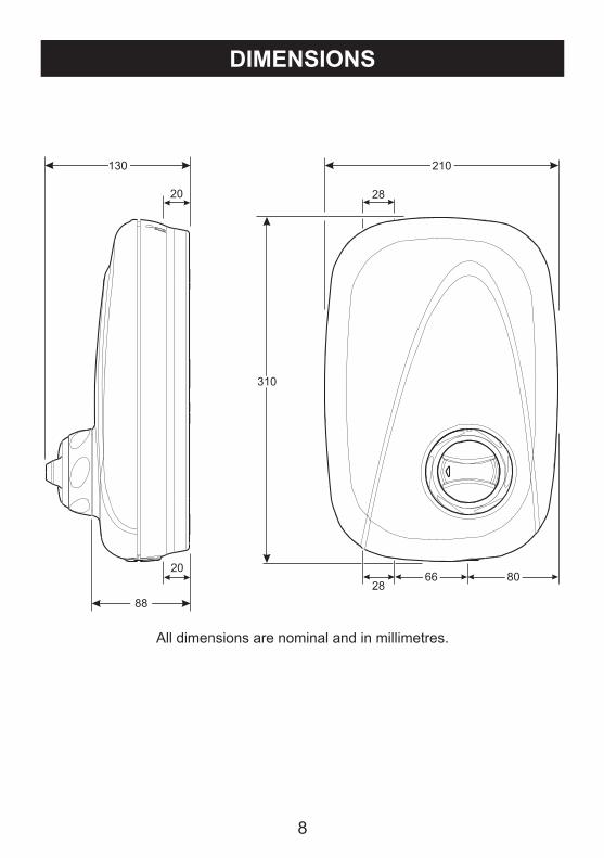
DIMENSIONS
All dimensions are nominal and in millimetres.
28
28
20
20
130
88
66 80
310
210
9
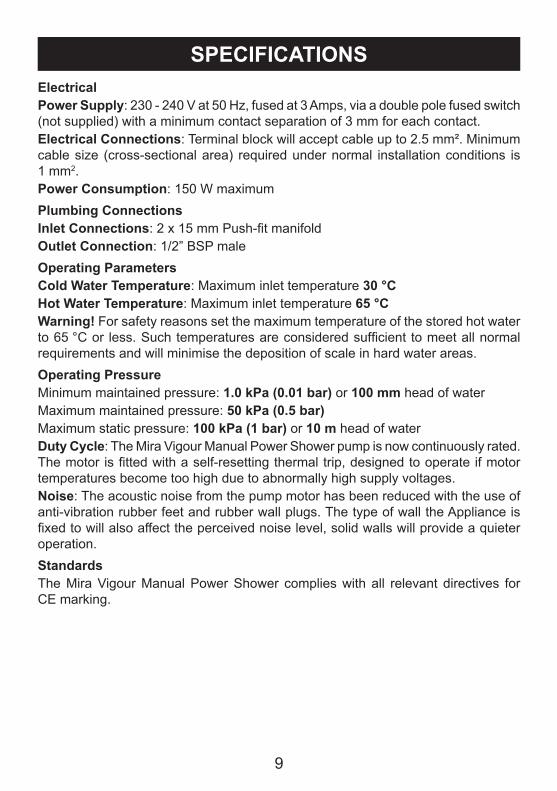
ElectricalPower Supply: 230 - 240 V at 50 Hz, fused at 3 Amps, via a double pole fused switch (not supplied) with a minimum contact separation of 3 mm for each contact.Electrical Connections: Terminal block will accept cable up to 2.5 mm². Minimum cable size (cross-sectional area) required under normal installation conditions is 1 mm2.Power Consumption: 150 W maximumPlumbing ConnectionsInlet Connections: 2 x 15 mm Push-fit manifoldOutlet Connection: 1/2” BSP maleOperating ParametersCold Water Temperature: Maximum inlet temperature 30 °CHot Water Temperature: Maximum inlet temperature 65 °CWarning! For safety reasons set the maximum temperature of the stored hot water to 65 °C or less. Such temperatures are considered sufficient to meet all normal requirements and will minimise the deposition of scale in hard water areas.Operating PressureMinimum maintained pressure: 1.0 kPa (0.01 bar) or 100 mm head of waterMaximum maintained pressure: 50 kPa (0.5 bar)Maximum static pressure: 100 kPa (1 bar) or 10 m head of waterDuty Cycle: The Mira Vigour Manual Power Shower pump is now continuously rated. The motor is fitted with a self-resetting thermal trip, designed to operate if motor temperatures become too high due to abnormally high supply voltages.Noise: The acoustic noise from the pump motor has been reduced with the use of anti-vibration rubber feet and rubber wall plugs. The type of wall the Appliance is fixed to will also affect the perceived noise level, solid walls will provide a quieter operation.StandardsThe Mira Vigour Manual Power Shower complies with all relevant directives for CE marking.
SPECIFICATIONS
10
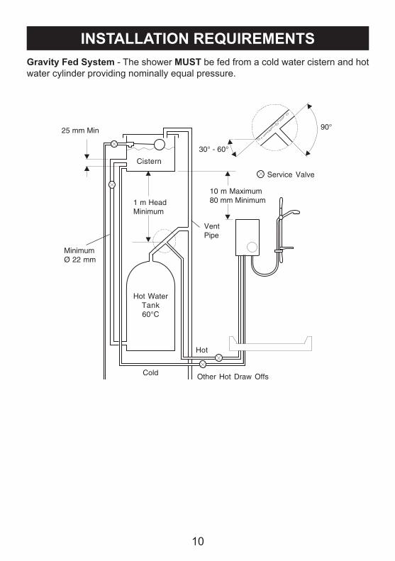
Gravity Fed System - The shower MUST be fed from a cold water cistern and hot water cylinder providing nominally equal pressure.
INSTALLATION REQUIREMENTS
25 mm Min
Cistern
30° - 60°
90°
Service Valve
10 m Maximum80 mm Minimum
VentPipe
Other Hot Draw Offs
Hot
Cold
Hot WaterTank60°C
1 m HeadMinimum
MinimumØ 22 mm
11
INSTALLATIONGeneral1. Do not take risks with plumbing or electrical equipment.2. Do not install the shower unit in a position where it could become frozen.3. Isolate electrical and water supplies before proceeding with the installation of
the shower unit.4. The shower unit must be fed from a cold water storage cistern and hot water
cylinder with equal pressures. The shower unit must not be connected to a mains cold water supply, unvented high pressure systems or multi-point/combination gas water heaters.
5. The installation must be carried out by a competent installer.6. Decide on a suitable position for the shower unit (minimum distance of 200 mm
from the ceiling to allow for the fitting and removal of the cover). The position of the appliance and the shower fittings must provide a minimum gap of 25 mm between the spillover level of the shower tray/bath and the handset, to prevent backsiphonage.
7. Avoid layouts where the hose will be sharply kinked. This may reduce the life of the hose.
8. The shower unit is designed for surface mounting only and must not be recessed into any wall or cavity, or tiled up to, as this prevents air circulating to the rear of the unit.
Electrical1. The shower unit must be earthed by connecting the supply cable earth
conductor to the earth terminal. Supplementary bonding: Within the bathroom or shower room, all accessible
conductive parts of electrical equipment and extraneous conductive parts that are likely to introduce earth potential, must be electrically bonded to earth using a minimum cable size of 4.0 mm2 if the cable is not mechanically protected (2.5 mm2 if mechanically protected).
2. Power supply cable must have a minimum cross sectional area of 1 mm².3. Power supply must be 230-240 V at 50 Hz. The isolating switch must be double
pole switched, fused at 3 Amps, with at least a 3 mm contact separation gap to each pole.
4. Do not turn the electrical supply on until all plumbing connections have been made and the shower unit has been commissioned as the unit must not be operated dry.
5. A 30 mA RCD (residual current device) must be fitted. This may be part of the consumer unit or a separate unit.
6. Fuses do not give personal protection against electric shock.
12
Plumbing1. A minimum storage capacity of cold water of 230 litres (50 gallons) is required
to provide adequate showering time. Insufficient storage may result in the pump being run dry.
2. Layout and sizing of pipework must be such that nominally equal inlet supply pressures are achieved and the effects on the shower performance of other draw-offs are minimised. Make sure the shower unit is the first draw-off from the water supply.
3. Avoid routing the high level hot feed pipe upward to the same level as the cold tank e.g. into loft space, as air locks may result.
4. Do not solder supply pipework connected to the shower unit as heat transfer may damage plastic components.
5. Do not use jointing compounds on the shower unit joints, they may cause damage to the mechanism inside.
6. Do not insert fingers into the push fit connections.7. The supply pipe ends must be free from burrs, as these will damage the push
fit seals.8. Do not use stainless steel piping for inlet pipework.9. If plated tubing is used for inlet pipework remove the plating from the last 25 mm
of the tube to make sure of a good seal.10. 15 mm polythene plastic pipe suitable for hot water may be used to supply the
shower unit, but internal pipe supports must be used.11. Supplies must be thoroughly flushed to remove any debris before connecting
the shower unit.12. Fit non-restrictive (free-flowing) isolating valves in the inlet pipework to the
appliance. Make sure isolating valves can be accessed easily.
13
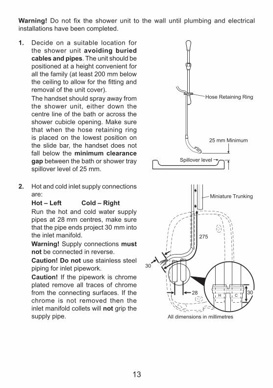
Warning! Do not fix the shower unit to the wall until plumbing and electrical installations have been completed.
1. Decide on a suitable location for the shower unit avoiding buried cables and pipes. The unit should be positioned at a height convenient for all the family (at least 200 mm below the ceiling to allow for the fitting and removal of the unit cover).
The handset should spray away from the shower unit, either down the centre line of the bath or across the shower cubicle opening. Make sure that when the hose retaining ring is placed on the lowest position on the slide bar, the handset does not fall below the minimum clearance gap between the bath or shower tray spillover level of 25 mm.
2. Hot and cold inlet supply connections are:
Hot – Left Cold – Right Run the hot and cold water supply
pipes at 28 mm centres, make sure that the pipe ends project 30 mm into the inlet manifold.
Warning! Supply connections must not be connected in reverse.
Caution! Do not use stainless steel piping for inlet pipework.
Caution! If the pipework is chrome plated remove all traces of chrome from the connecting surfaces. If the chrome is not removed then the inlet manifold collets will not grip the supply pipe.
25 mm Minimum
Spillover level
Hose Retaining Ring
All dimensions in millimetres
Miniature Trunking
275
28
30
30H C
14
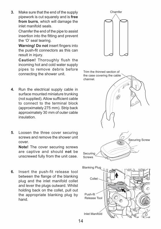
3. Make sure that the end of the supply pipework is cut squarely and is free from burrs, which will damage the inlet manifold seals.
Chamfer the end of the pipe to assist insertion into the fitting and prevent the ‘O’ seal tearing.
Warning! Do not insert fingers into the push-fit connectors as this can result in injury.
Caution! Thoroughly flush the incoming hot and cold water supply pipes to remove debris before connecting the shower unit.
4. Run the electrical supply cable in surface mounted miniature trunking (not supplied). Allow sufficient cable to connect to the terminal block (approximately 275 mm). Strip back approximately 30 mm of outer cable insulation.
5. Loosen the three cover securing screws and remove the shower unit cover.
Note! The cover securing screws are captive and should not be unscrewed fully from the unit case.
6. Insert the push-fit release tool between the flange of the blanking plug and the inlet manifold collet and lever the plugs outward. Whilst holding back on the collet, pull out the appropriate blanking plug by hand.
Chamfer
Trim the thinned section of the case covering the cable channel.
Push-fit Release Tool
Blanking Plug
Inlet Manifold
Collet
Securing Screws
Securing Screw
15
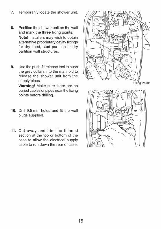
7. Temporarily locate the shower unit.
8. Position the shower unit on the wall and mark the three fixing points.
Note! Installers may wish to obtain alternative proprietary cavity fixings for dry lined, stud partition or dry partition wall structures.
9. Use the push-fit release tool to push the grey collars into the manifold to release the shower unit from the supply pipes.
Warning! Make sure there are no buried cables or pipes near the fixing points before drilling.
10. Drill 9.5 mm holes and fit the wall plugs supplied.
11. Cut away and trim the thinned section at the top or bottom of the case to allow the electrical supply cable to run down the rear of case.
Fixing Points
16
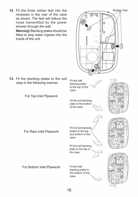
12. Fit the three rubber feet into the recesses in the rear of the case as shown. The feet will reduce the noise transmitted by the power shower through the wall.
Warning! Blanking plates should be fitted to stop water ingress into the inside of the unit.
13. Fit the blanking plates to the unit case in the following manner.
For Top Inlet Pipework
For Rear Inlet Pipework
For Bottom Inlet Pipework
Rubber Feet
Fit the full blanking plates to the top and bottom of the case.
Fit the full blanking plate to the bottom of the case.
Fit the half blanking plate to the top of the case.
Fit the half blanking plate to the bottom of the case.
Fit the full blanking plate to the top of the case.
17
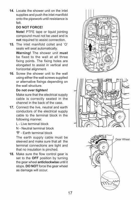
14. Locate the shower unit on the inlet supplies and push the inlet manifold onto the pipework until resistance is felt.
DO NOT FORCE! Note! PTFE tape or liquid jointing
compound must not be used and is not required to assist connection.
15. The inlet manifold collet and ‘O’ seals will seal automatically.
Warning! The shower unit must be fixed to the wall at all three fixing points. The fixing holes are elongated to assist in vertical and horizontal alignment.
16. Screw the shower unit to the wall using either the wall screws supplied or alternative fixings depending on the wall structure.
Do not over tighten! Make sure that the electrical supply
cable is correctly seated in the channel in the back of the case.
17. Connect the live, neutral and earth conductors of the electrical supply cable to the terminal block in the following manner.
L - Live terminal block N - Neutral terminal block - Earth terminal block The earth supply cable must be
sleeved and make sure that all the terminal connections are tight and that no insulation is pinched.
18. Make sure the flow control gear is set to the OFF position by turning the gear wheel anticlockwise until it stops. DO NOT force the gear wheel as damage will occur.
Gear Wheel
18
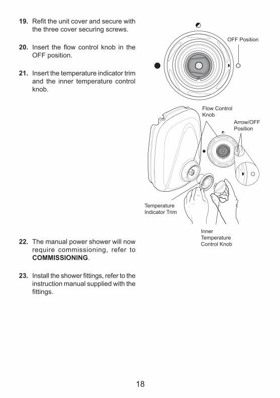
19. Refit the unit cover and secure with the three cover securing screws.
20. Insert the flow control knob in the OFF position.
21. Insert the temperature indicator trim and the inner temperature control knob.
22. The manual power shower will now require commissioning, refer to COMMISSIONING.
23. Install the shower fittings, refer to the instruction manual supplied with the fittings.
Inner Temperature Control Knob
Temperature Indicator Trim
OFF Position
Flow Control Knob
Arrow/OFF Position
19
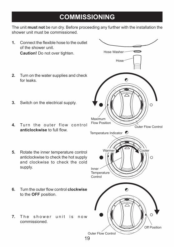
COMMISSIONINGThe unit must not be run dry. Before proceeding any further with the installation the shower unit must be commissioned.
1. Connect the flexible hose to the outlet of the shower unit.
Caution! Do not over tighten.
2. Turn on the water supplies and check for leaks.
3. Switch on the electrical supply.
4. Tu rn t he ou te r f l ow con t ro l anticlockwise to full flow.
5. Rotate the inner temperature control anticlockwise to check the hot supply and clockwise to check the cold supply.
6. Turn the outer flow control clockwise to the OFF position.
7. T h e s h o w e r u n i t i s n o w commissioned.
Inner Temperature Control
Temperature Indicator
CoolerWarmer
Outer Flow Control
Maximum Flow Position
Outer Flow Control
Off Position
Hose Washer
Hose
20
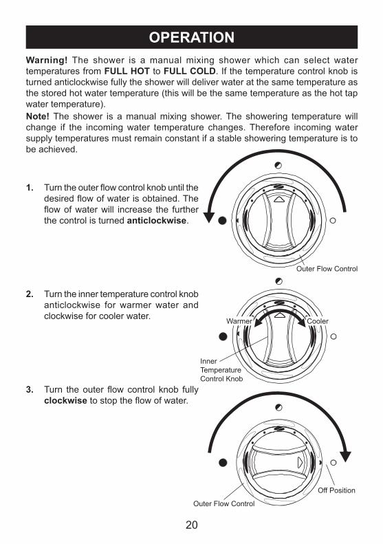
OPERATION
1. Turn the outer flow control knob until the desired flow of water is obtained. The flow of water will increase the further the control is turned anticlockwise.
2. Turn the inner temperature control knob anticlockwise for warmer water and clockwise for cooler water.
3. Turn the outer flow control knob fully clockwise to stop the flow of water.
Warning! The shower is a manual mixing shower which can select water temperatures from FULL HOT to FULL COLD. If the temperature control knob is turned anticlockwise fully the shower will deliver water at the same temperature as the stored hot water temperature (this will be the same temperature as the hot tap water temperature).Note! The shower is a manual mixing shower. The showering temperature will change if the incoming water temperature changes. Therefore incoming water supply temperatures must remain constant if a stable showering temperature is to be achieved.
Inner Temperature Control Knob
CoolerWarmer
Outer Flow Control
Outer Flow Control
Off Position

21
FAULT DIAGNOSISFault Diagnosis - User MaintenanceThe appliance is fully performance tested after assembly. Providing it has been correctly installed and is operated as advised, difficulties should not arise. In the unlikely event that you experience problems with your appliance then the following procedure will enable you to undertake basic fault finding before contacting the person responsible for installing your shower.
Malfunction Cause RemedyThe shower temperature is too cold.
The hot water cylinder temperature is less than 12 °C above the shower temperature.
Adjust the cylinder temperature. Note! It is recommended that stored water temperatures does not exceed 65 °C.
The blend temperature is unstable.
The spray plate is blocked.
The inlet filters are blocked.The isolating valve is partially closed.Faulty plumbing system.
Clean the spray plate. Refer to the instruction manual supplied with the shower fittings.Contact your installer.Open the isolating valve.
Contact your installer.The pump does not operate.
Electrical supply failure.PCB failure.Potentiometer failure.The motor overheated and the thermal switch operated.
Contact your installer.Contact your installer.Contact your installer.If the thermal switch operates repeatedly, contact customer service for further advice.
Low or no water flow.
Isolating valves are closed.Inlet filters blocked.Check the isolating valves are fitted incorrectly.The appliance is sited above cold water storage cistern.
Faulty plumbing system (airlock).
Open the isolating valves.Contact your installer.Contact your installer.
The appliance is not suitable for negative head installations. Refer to INSTALLATION REQUIREMENTS.Contact your installer.
22
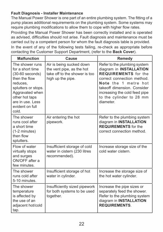
Fault Diagnosis - Installer MaintenanceThe Manual Power Shower is one part of an entire plumbing system. The fitting of a pump places additional requirements on the plumbing system. Some systems may require plumbing modifications to allow them to cope with higher flow rates. Providing the Manual Power Shower has been correctly installed and is operated as advised, difficulties should not arise. Fault diagnosis and maintenance must be carried out by a competent person for whom the fault diagnosis table is provided.In the event of any of the following tests failing, re-check as appropriate before contacting the Customer Support Department, (refer to the Back Cover).
Malfunction Cause RemedyThe shower runs for a short time (30-60 seconds) then the flow reduces, splutters or stops. Aggravated when other hot taps are in use. Less evident on full cold.
Air is being sucked down the vent pipe, as the hot take off to the shower is too high up the pipe.
Refer to the plumbing system diagram in INSTALLATION REQUIREMENTS for the correct connection method. Note t he 1 met re ho t takeoff dimension. Consider increasing the cold feed pipe to the cylinder to 28 mm diameter.
The shower runs cool after a short time (1-2 minutes) then flow splutters.
Air entering the hot pipework.
Refer to the plumbing system diagram in INSTALLATION REQUIREMENTS for the correct connection method.
Flow of water virtually stops and surges ON/OFF after a few minutes.
Insufficient storage of cold water in cistern (230 litres recommended).
Increase storage size of the cold water cistern.
The shower runs cold after 5-10 minutes.
Insufficient storage of hot water in cylinder.
Increase the storage size of the hot water cylinder.
The shower temperature is affected by the use of an adjacent hot/cold tap.
Insufficiently sized pipework for both systems to be used together.
Increase the pipe sizes or separately feed the shower. Refer to the plumbing system diagram in INSTALLATION REQUIREMENTS.
23
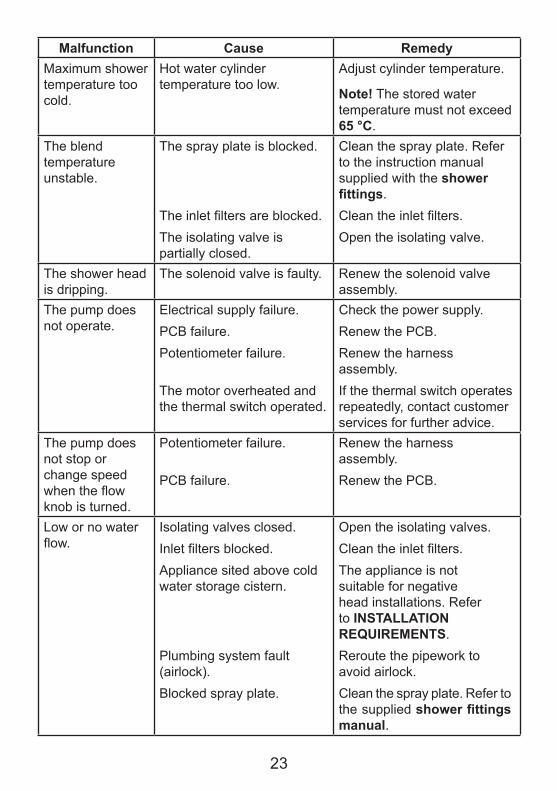
Malfunction Cause RemedyMaximum shower temperature too cold.
Hot water cylinder temperature too low.
Adjust cylinder temperature.
Note! The stored water temperature must not exceed 65 °C.
The blend temperature unstable.
The spray plate is blocked.
The inlet filters are blocked.The isolating valve is partially closed.
Clean the spray plate. Refer to the instruction manual supplied with the shower fittings.Clean the inlet filters.Open the isolating valve.
The shower head is dripping.
The solenoid valve is faulty. Renew the solenoid valve assembly.
The pump does not operate.
Electrical supply failure.PCB failure.Potentiometer failure.
The motor overheated and the thermal switch operated.
Check the power supply.Renew the PCB.Renew the harness assembly.If the thermal switch operates repeatedly, contact customer services for further advice.
The pump does not stop or change speed when the flow knob is turned.
Potentiometer failure.
PCB failure.
Renew the harness assembly.Renew the PCB.
Low or no water flow.
Isolating valves closed.Inlet filters blocked.Appliance sited above cold water storage cistern.
Plumbing system fault (airlock).Blocked spray plate.
Open the isolating valves.Clean the inlet filters.The appliance is not suitable for negative head installations. Refer to INSTALLATION REQUIREMENTS.Reroute the pipework to avoid airlock.Clean the spray plate. Refer to the supplied shower fittings manual.
24
Warning! There are no user serviceable components beneath the cover of the appliance. Only a competent tradesperson should remove the cover.Before removing the cover the electricity supply must be turned off at the mains and, if applicable, the appropriate circuit fuse removed. Mains electrical connections are exposed when the cover is removed.Before replacing any parts make sure that the underlying cause of the malfunction has been resolved.
CleaningMany household cleaners contain abrasives and chemical substances, and should not be used for cleaning plated or plastic fittings. These finishes should be cleaned with a mild washing up detergent or soap solution, and then wiped dry using a soft cloth.
HandsetPoor shower performance can be avoided by regular cleaning of the handset. Use your thumb or soft cloth to wipe the rubber nozzles. The handset must also be descaled regularly.
MAINTENANCE
25
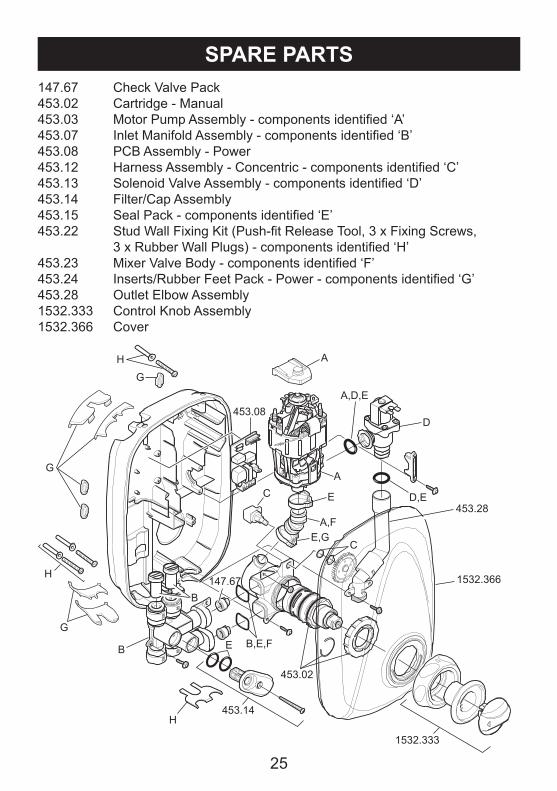
SPARE PARTS147.67 Check Valve Pack453.02 Cartridge - Manual 453.03 Motor Pump Assembly - components identified ‘A’453.07 Inlet Manifold Assembly - components identified ‘B’453.08 PCB Assembly - Power453.12 Harness Assembly - Concentric - components identified ‘C’453.13 Solenoid Valve Assembly - components identified ‘D’453.14 Filter/Cap Assembly453.15 Seal Pack - components identified ‘E’453.22 Stud Wall Fixing Kit (Push-fit Release Tool, 3 x Fixing Screws,
3 x Rubber Wall Plugs) - components identified ‘H’453.23 Mixer Valve Body - components identified ‘F’453.24 Inserts/Rubber Feet Pack - Power - components identified ‘G’453.28 Outlet Elbow Assembly1532.333 Control Knob Assembly1532.366 Cover
147.67
453.02
453.14
A
453.08
B
H
A,D,E
D,E
B
D
1532.333
G
453.28A,F
A
E,G
E
B,E,FE
C
C
G
G
H
H 1532.366
26
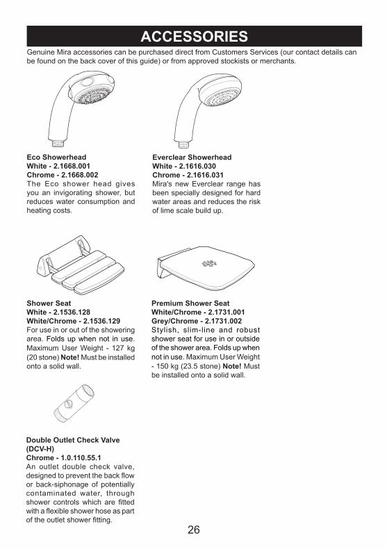
ACCESSORIESGenuine Mira accessories can be purchased direct from Customers Services (our contact details can be found on the back cover of this guide) or from approved stockists or merchants.
Eco ShowerheadWhite - 2.1668.001Chrome - 2.1668.002The Eco shower head gives you an invigorating shower, but reduces water consumption and heating costs.
Everclear ShowerheadWhite - 2.1616.030Chrome - 2.1616.031Mira's new Everclear range has been specially designed for hard water areas and reduces the risk of lime scale build up.
Premium Shower SeatWhite/Chrome - 2.1731.001Grey/Chrome - 2.1731.002Stylish, slim-line and robust shower seat for use in or outside of the shower area. Folds up when not in use. Maximum User Weight - 150 kg (23.5 stone) Note! Must be installed onto a solid wall.
Double Outlet Check Valve(DCV-H)Chrome - 1.0.110.55.1An outlet double check valve, designed to prevent the back flow or back-siphonage of potentially contaminated water, through shower controls which are fitted with a flexible shower hose as part of the outlet shower fitting.
Shower SeatWhite - 2.1536.128White/Chrome - 2.1536.129For use in or out of the showering area. Folds up when not in use. Maximum User Weight - 127 kg (20 stone) Note! Must be installed onto a solid wall.

27
NOTES
281088850-W2-F (B85M) © Kohler Mira Limited, April 2016
CUSTOMER SERVICE
Mira is a registered trade mark of Kohler Mira Limited.
The company reserves the right to alter
14648
Guarantee
guarantee which starts from date of purchase. This guarantee only applies in the United Kingdom and Republic of Ireland. To activate this guarantee, please return your completed registration card, visit our website or free phone 0800 5978551 within 30 days of purchase (UK only).Within the guarantee period we will resolve defects in materials or workmanship, free of charge, by repairing or replacing parts or product as we may choose.This guarantee is in addition to your statutory rights and is subject to the following conditions :
● The guarantee applies solely to the original installation under normal use and to the original purchaser only. The product must be installed and maintained in accordance with the instructions given in this guide.
● Servicing must only be undertaken by us or our appointed representative. Note! If a service visit is required the product mustbe fully installed and connected to services.
● Repair under this guarantee does not extend the original expiry date. The guarantee on any replacement parts or product ends at the original expiry date.
● reserve the right to supply replacement parts only.
The guarantee does not cover:● Call out charges for non product faults (such as
damage or performance issues arising from incorrect installation, improper use, inappropriate cleaning, lack of maintenance, build up of limescale, frost damage, chemical attack,
where no fault has been found with the product.● Water or electrical supply, waste and isolation
issues.● Compensation for loss of use of the product or
consequential or indirect loss of any kind.● Damage or defects caused if the product is
us or our appointed representative.●
● Accidental or wilful damage. ● Products purchased ex-showroom display.
What to do if something goes wrongIf your product does not work correctly refer to this manual for fault diagnosis and check that it is installed and commissioned in accordance with our instructions.If this does not resolve the issue, contact us for help and advice.
Helpdesk ServiceContact our Customer Services Team for product advice, to purchase spare parts or
accessories or to set up service visit. You can contact us via phone or e-mail - contact details below.Please provide your model name, power rating (if applicable) and date of purchase.
Mira Showers Website (www.mirashowers.co.uk)Visit our website to register your guarantee,
download user guides, diagnose faults, purchase our full range of accessories and popular spares, or request a service visit.
Spares and AccessoriesWe hold the largest stocks of genuine Mira spares and accessories.Contact us for a
price or visit our website to purchase items from our accessory range and popular spares. (Only available in the United Kingdom )
Service/RepairsNo one knows our products better than our nationwide team of Service Technicians. We
can carry out service or repair work to your product both during and after the guarantee period. (Only available in the United Kingdom and Republic of
To Contact Us: Eire Only01 531 9337
E-mail: [email protected]
To Contact Us: UK0844 571 5000Calls cost 7p per minute plus your phone company’s access chargeFax: 01242 282595
Email – Visit www.mirashowers.co.uk/contactus
By Post: Mira Customer Services Dept, Cromwell Road, Cheltenham, Gloucestershire GL52 5EP
Your product has the benefit of our manufacturer’s
For shower fittings or consumable items we
corrosion, system debris or blocked filters) or
repaired or modified by persons not authorised by
TMV3 healthcare schemes
Routine maintenance or replacement parts torepaired or modified by persons not authorised bycomply with the requirements of theTMV2 orrepaired or modified by persons not authorised by
product specifications without notice.
Ireland) Ask about our fixed price service repairs.


