474
Compass OWNER’ S MANUAL 2010
| Date post: | 01-Nov-2014 |
| Category: |
Documents |
| Upload: | rafael-monzon |
| View: | 69 times |
| Download: | 0 times |

CompassOWNE R ’ S MANUAL
2 0 1 0
TABLE OF CONTENTSSECTION PAGE
1 INTRODUCTION . . . . . . . . . . . . . . . . . . . . . . . . . . . . . . . . . . . . . . . . . . . . . . . . . . . . . . . . . . . . 3
2 THINGS TO KNOW BEFORE STARTING YOUR VEHICLE . . . . . . . . . . . . . . . . . . . . . . . . . . . . . .9
3 UNDERSTANDING THE FEATURES OF YOUR VEHICLE . . . . . . . . . . . . . . . . . . . . . . . . . . . . . 85
4 UNDERSTANDING YOUR INSTRUMENT PANEL . . . . . . . . . . . . . . . . . . . . . . . . . . . . . . . . . . 177
5 STARTING AND OPERATING . . . . . . . . . . . . . . . . . . . . . . . . . . . . . . . . . . . . . . . . . . . . . . . . 273
6 WHAT TO DO IN EMERGENCIES . . . . . . . . . . . . . . . . . . . . . . . . . . . . . . . . . . . . . . . . . . . . . 357
7 MAINTAINING YOUR VEHICLE . . . . . . . . . . . . . . . . . . . . . . . . . . . . . . . . . . . . . . . . . . . . . . 375
8 MAINTENANCE SCHEDULES . . . . . . . . . . . . . . . . . . . . . . . . . . . . . . . . . . . . . . . . . . . . . . . . . 425
9 IF YOU NEED CONSUMER ASSISTANCE . . . . . . . . . . . . . . . . . . . . . . . . . . . . . . . . . . . . . . . . 445
10 INDEX . . . . . . . . . . . . . . . . . . . . . . . . . . . . . . . . . . . . . . . . . . . . . . . . . . . . . . . . . . . . . . . . . . . 455
1
2
3
4
5
6
7
8
9
10

INTRODUCTION
CONTENTS
� Introduction . . . . . . . . . . . . . . . . . . . . . . . . . . . 4
� Rollover Warning . . . . . . . . . . . . . . . . . . . . . . . 4
� How To Use This Manual . . . . . . . . . . . . . . . . . . 5
� Warnings And Cautions . . . . . . . . . . . . . . . . . . . 7
� Vehicle Identification Number . . . . . . . . . . . . . . 7
� Vehicle Modifications/Alterations . . . . . . . . . . . . 8
1

INTRODUCTIONCongratulations on selecting your new Chrysler GroupLLC vehicle. Be assured that it represents precisionworkmanship, distinctive styling, and high quality - allessentials that are traditional to our vehicles.
This Owner’s Manual has been prepared with the assis-tance of service and engineering specialists to acquaintyou with the operation and maintenance of your vehicle.It is supplemented by a Warranty Information Booklet,located on the DVD, and various customer-orienteddocuments. Please take the time to read these publica-tions carefully. Following the instructions and recom-mendations in this manual will help assure safe andenjoyable operation of your vehicle.
NOTE: After you read the manual, it should be storedin the vehicle for convenient referencing and remainwith the vehicle when sold, so that the new owner willbe aware of all safety warnings.
When it comes to service, remember that your authorizeddealer knows your vehicle best, has factory-trained tech-nicians and genuine MOPAR� parts, and cares aboutyour satisfaction.
ROLLOVER WARNINGUtility vehicles have a significantly higher rollover ratethan other types of vehicles. This vehicle has a higherground clearance and a higher center of gravity thanmany passenger cars. It is capable of performing better ina wide variety of off-road applications. Driven in anunsafe manner, all vehicles can go out of control. Becauseof the higher center of gravity, if this vehicle is out ofcontrol it may roll over when some other vehicles maynot.
Do not attempt sharp turns, abrupt maneuvers, or otherunsafe driving actions that can cause loss of vehicle
4 INTRODUCTION

control. Failure to operate this vehicle safely may resultin an accident, rollover of the vehicle, and severe or fatalinjury. Drive carefully.
Failure to use driver and passenger seat belts providedis a major cause of severe or fatal injury. In fact, the U.S.government notes that the universal use of existing seat
belts could cut the highway death toll by 10,000 or moreeach year and could reduce disabling injuries by twomillion annually. In a rollover crash, an unbelted personis significantly more likely to die than a person wearinga seat belt. Always buckle up.
HOW TO USE THIS MANUALConsult the Table of Contents to determine which sectioncontains the information you desire.
Since the specification of your vehicle depends on theitems of equipment ordered, certain descriptions andillustrations may differ from your vehicle’s equipment
The detailed index at the back of this Owner’s Manualcontains a complete listing of all subjects.
Consult the following table for a description of thesymbols that may be used on your vehicle or throughoutthis Owner’s Manual:
Rollover Warning Label
1
INTRODUCTION 5

6 INTRODUCTION

WARNINGS AND CAUTIONSThis Owner’s Manual contains WARNINGS against op-erating procedures that could result in an accident orbodily injury. It also contains CAUTIONS against proce-dures that could result in damage to your vehicle. If youdo not read this entire manual, you may miss importantinformation. Observe all Warnings and Cautions.
VEHICLE IDENTIFICATION NUMBERThe Vehicle Identification Number (VIN) is found on theleft front corner of the instrument panel, visible throughthe windshield. This number also appears on the vehicleregistration and title. Vehicle Identification Number
1
INTRODUCTION 7

VEHICLE MODIFICATIONS/ALTERATIONS
WARNING!
Any modifications or alterations to this vehicle couldseriously affect its roadworthiness and safety andmay lead to an accident resulting in serious injury ordeath.
8 INTRODUCTION
THINGS TO KNOW BEFORE STARTING YOUR VEHICLE
CONTENTS
� A Word About Your Keys . . . . . . . . . . . . . . . . . 12
▫ Ignition Key Removal . . . . . . . . . . . . . . . . . . 12
▫ Locking Doors With A Key . . . . . . . . . . . . . . 15
▫ Key-In-Ignition Reminder . . . . . . . . . . . . . . . 15
� Sentry Key� . . . . . . . . . . . . . . . . . . . . . . . . . . 15
▫ Replacement Keys . . . . . . . . . . . . . . . . . . . . . 16
▫ Customer Key Programming . . . . . . . . . . . . . 17
▫ General Information . . . . . . . . . . . . . . . . . . . 18
� Vehicle Security Alarm — If Equipped . . . . . . . . 18
▫ To Set The Security Alarm . . . . . . . . . . . . . . . 18
▫ To Disarm The System . . . . . . . . . . . . . . . . . 19
▫ Vehicle Security Alarm Manual Override . . . . . 19
� Remote Keyless Entry (RKE) — If Equipped . . . 19
▫ To Unlock The Doors And Liftgate . . . . . . . . . 20
▫ Remote Key Unlock, Driver Door/All FirstPress . . . . . . . . . . . . . . . . . . . . . . . . . . . . . . 20
▫ Illuminated Approach — If Equipped . . . . . . . 21
2

▫ To Lock The Doors And Liftgate . . . . . . . . . . 21
▫ Sound Horn With Remote Key Lock . . . . . . . . 21
▫ Flash Lights With Remote Key Lock/Unlock . . 22
▫ Using The Panic Alarm . . . . . . . . . . . . . . . . . 23
▫ Programming Additional Transmitters . . . . . . 23
▫ General Information . . . . . . . . . . . . . . . . . . . 23
▫ Transmitter Battery Replacement . . . . . . . . . . 24
� Remote Starting System — If Equipped . . . . . . . 25
▫ How To Use Remote Start . . . . . . . . . . . . . . . 25
� Door Locks . . . . . . . . . . . . . . . . . . . . . . . . . . . 28
▫ Manual Door Locks . . . . . . . . . . . . . . . . . . . 28
▫ Power Door Locks . . . . . . . . . . . . . . . . . . . . 29
▫ Child-Protection Door Lock System(Rear Doors) . . . . . . . . . . . . . . . . . . . . . . . . . 32
� Power Windows — If Equipped . . . . . . . . . . . . 33
▫ Power Window Switches . . . . . . . . . . . . . . . . 33
▫ Auto-Down . . . . . . . . . . . . . . . . . . . . . . . . . 34
▫ Window Lockout Switch . . . . . . . . . . . . . . . . 35
� Liftgate . . . . . . . . . . . . . . . . . . . . . . . . . . . . . 35
� Occupant Restraints . . . . . . . . . . . . . . . . . . . . . 37
▫ Lap/Shoulder Belts . . . . . . . . . . . . . . . . . . . . 39
▫ Adjustable Upper Shoulder Belt Anchorage . . . 44
▫ Second Row Center Lap/Shoulder BeltOperating Instructions . . . . . . . . . . . . . . . . . . 45
▫ Lap/Shoulder Belt Untwisting Procedure . . . . 48
10 THINGS TO KNOW BEFORE STARTING YOUR VEHICLE
▫ Automatic Locking Retractors (ALR)Mode — If Equipped . . . . . . . . . . . . . . . . . . . 48
▫ Seat Belt Pretensioners — If Equipped . . . . . . 49
▫ Supplemental Rear Impact Active HeadRestraints (AHR) . . . . . . . . . . . . . . . . . . . . . . 49
▫ Enhanced Seat Belt Use Reminder System(BeltAlert�) . . . . . . . . . . . . . . . . . . . . . . . . . 53
▫ Seat Belt Extender . . . . . . . . . . . . . . . . . . . . . 55
▫ Seat Belts And Pregnant Women . . . . . . . . . . 55
▫ Supplemental Restraint System (SRS) -Airbags . . . . . . . . . . . . . . . . . . . . . . . . . . . . 56
▫ Advanced Front Airbag Features . . . . . . . . . . 58
▫ Airbag Deployment Sensors And Controls . . . 63
▫ Event Data Recorder (EDR) . . . . . . . . . . . . . . 70
▫ Child Restraint . . . . . . . . . . . . . . . . . . . . . . . 72
� Engine Break-In Recommendations . . . . . . . . . . 80
� Safety Tips . . . . . . . . . . . . . . . . . . . . . . . . . . . 81
▫ Transporting Passengers . . . . . . . . . . . . . . . . 81
▫ Exhaust Gas . . . . . . . . . . . . . . . . . . . . . . . . . 81
▫ Safety Checks You Should Make Inside TheVehicle . . . . . . . . . . . . . . . . . . . . . . . . . . . . . 82
▫ Periodic Safety Checks You Should MakeOutside The Vehicle . . . . . . . . . . . . . . . . . . . 83
2
THINGS TO KNOW BEFORE STARTING YOUR VEHICLE 11

A WORD ABOUT YOUR KEYSThe authorized dealer that sold you your new vehicle hasthe key code numbers for your vehicle locks. Thesenumbers can be used to order duplicate keys. Ask yourauthorized dealer for these numbers and keep them in asafe place.
Ignition Key Removal
Automatic Transmission — If Equipped
1. Place the shift lever in PARK.
2. Turn the ignition switch to the ACC (Accessory)position.
3. Push the key and cylinder inward and rotate the key tothe LOCK position.
4. Remove the key from the ignition switch lock cylinder.
Vehicle Key
12 THINGS TO KNOW BEFORE STARTING YOUR VEHICLE

NOTE: If you try to remove the key before you place theshift lever in PARK, the key may become trapped tem-porarily in the ignition switch cylinder. If this occurs,rotate the key to the right slightly, then remove the key asdescribed. If a malfunction occurs, the system will trapthe key in the ignition cylinder to warn you that thissafety feature is inoperable. The engine can be startedand stopped but the key cannot be removed until youobtain service.
WARNING!
Never leave children alone in a vehicle. Leavingunattended children in a vehicle is dangerous for anumber of reasons. A child or others could be seri-ously or fatally injured. Do not leave the keys in theignition. A child could operate power windows,other controls, or move the vehicle.
Ignition Switch Positions
1 — LOCK 3 — ON2 — ACC (ACCESSORY) 4 — START
2
THINGS TO KNOW BEFORE STARTING YOUR VEHICLE 13
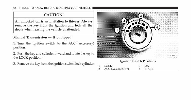
CAUTION!
An unlocked car is an invitation to thieves. Alwaysremove the key from the ignition and lock all thedoors when leaving the vehicle unattended.
Manual Transmission — If Equipped
1. Turn the ignition switch to the ACC (Accessory)position.
2. Push the key and cylinder inward and rotate the key tothe LOCK position.
3. Remove the key from the ignition switch lock cylinder.Ignition Switch Positions
1 — LOCK 3 — ON2 — ACC (ACCESSORY) 4 — START
14 THINGS TO KNOW BEFORE STARTING YOUR VEHICLE

Locking Doors With A KeyYou can insert the key with either side up. To lock thedoor, turn the key to the right. To unlock the door, turnthe key to the left. Refer to “Maintenance Procedures” in“Maintaining Your Vehicle” for further information.
Key-In-Ignition ReminderOpening the driver’s door when the key is in the ignitionand the ignition position is LOCK or ACC, sounds asignal to remind you to remove the key.
NOTE: With the driver’s door open and the key in theignition, the power door locks will not lock and RemoteKeyless Entry (RKE) transmitter will not function.
SENTRY KEY�The Sentry Key� Immobilizer System prevents unautho-rized vehicle operation by disabling the engine. Thesystem does not need to be armed or activated. Operationis automatic, regardless of whether the vehicle is lockedor unlocked.
The system uses ignition keys that have an embeddedelectronic chip (transponder) to prevent unauthorizedvehicle operation. Therefore, only keys that are pro-grammed to the vehicle can be used to start and operatethe vehicle. The system will shut the engine off in twoseconds if someone uses an invalid key to try to start theengine.
NOTE: A key that has not been programmed is alsoconsidered an invalid key, even if it is cut to fit theignition switch lock cylinder for that vehicle.
During normal operation, after turning on the ignitionswitch, the Vehicle Security Light will turn on for threeseconds for a bulb check. If the light remains on after thebulb check, it indicates that there is a problem with theelectronics. In addition, if the Vehicle Security Lightbegins to flash after the bulb check, it indicates thatsomeone used an invalid key to try to start the engine.Either of these conditions will result in the engine beingshut off after two seconds.
2
THINGS TO KNOW BEFORE STARTING YOUR VEHICLE 15
If the Vehicle Security Light turns on during normalvehicle operation (vehicle running for longer than 10 sec-onds), it indicates that there is a fault in the electronics.Should this occur, have the vehicle serviced as soon aspossible by an authorized dealer.
NOTE: The Sentry Key� Immobilizer System is notcompatible with some aftermarket remote starting sys-tems. Use of these systems may result in vehicle startingproblems and loss of security protection.
All of the keys provided with your new vehicle havebeen programmed to the vehicle electronics.
Replacement Keys
NOTE: Only keys that are programmed to the vehicleelectronics can be used to start and operate the vehicle.Once a Sentry Key� is programmed to a vehicle, it cannotbe programmed to any other vehicle.
CAUTION!
Always remove the Sentry Keys� from the vehicleand lock all doors when leaving the vehicle unat-tended.
At the time of purchase, the original owner is providedwith a four-digit Personal Identification Number (PIN).Keep the PIN in a secure location. This number isrequired for authorized dealer replacement of keys. Du-plication of keys may be performed at an authorizeddealer or by following the customer key programmingprocedure. This procedure consists of programming ablank key to the vehicle electronics. A blank key is onethat has never been programmed.
NOTE: When having the Sentry Key� ImmobilizerSystem serviced, bring all vehicle keys with you to anauthorized dealer.
16 THINGS TO KNOW BEFORE STARTING YOUR VEHICLE

Customer Key ProgrammingIf you have two valid Sentry Keys�, you can programnew Sentry Keys� to the system by performing thefollowing procedure:
1. Cut the additional Sentry Key� Transponder blank(s)to match the ignition switch lock cylinder key code.
2. Insert the first valid key into the ignition switch. Turnthe ignition switch to the ON position for at least threeseconds, but no longer than 15 seconds. Then, turn theignition switch to the LOCK position and remove the firstkey.
3. Insert the second valid key into the ignition switch.Turn the ignition switch to the ON position within15 seconds. After 10 seconds, a chime will sound. Inaddition, the Vehicle Security Light will begin to flash.Turn the ignition switch to the LOCK position andremove the second key.
4. Insert a blank Sentry Key� into the ignition switch.Turn the ignition switch to the ON position within60 seconds. After 10 seconds, a single chime will sound.In addition, the Vehicle Security Light will stop flashing.To indicate that programming is complete, the VehicleSecurity Light will turn on again for three seconds andthen turn off.
The new Sentry Key� is programmed. The RemoteKeyless Entry (RKE) transmitter will also be pro-grammed during this procedure.
Repeat this procedure to program up to eight keys. If youdo not have a programmed Sentry Key�, contact yourauthorized dealer for details.
NOTE: If a programmed key is lost, see your authorizeddealer to have all remaining keys erased from the sys-tem’s memory. This will prevent the lost key fromstarting your vehicle. The remaining keys must then be
2
THINGS TO KNOW BEFORE STARTING YOUR VEHICLE 17

reprogrammed. All vehicle keys must be taken to anauthorized dealer at the time of service to bereprogrammed.
General InformationThe Sentry Key� system complies with FCC rules Part 15and with RSS-210 of Industry Canada. Operation issubject to the following conditions:
• This device may not cause harmful interference.
• This device must accept any interference that may bereceived, including interference that may cause undes-ired operation.
VEHICLE SECURITY ALARM — IF EQUIPPEDThis Vehicle Security Alarm monitors the doors, liftgate,and ignition switch for unauthorized operation.
When the alarm is activated, the Vehicle Security Alarmprovides both audio and visual signals. The horn willsound, the headlights, park lamps and/or turn signals
will flash repeatedly for three minutes. If the disturbanceis still present (driver’s door, passenger door, other doors,ignition) after three minutes, the parking lights and taillights will flash for an additional 15 minutes.
To Set The Security Alarm
1. Remove the key from the ignition switch and get outof the vehicle.
2. Lock the door using either the power door LOCKswitch or the Remote Keyless Entry (RKE) transmitterand close all doors.
3. The Vehicle Security Light in the instrument clusterwill flash rapidly for approximately 16 seconds. Thisshows that the Vehicle Security Alarm is arming. Duringthis period, if a door is opened, the ignition switch isturned ON, or the power door locks are unlocked in anymanner, the Vehicle Security Alarm will automatically
18 THINGS TO KNOW BEFORE STARTING YOUR VEHICLE
disarm. After approximately 16 seconds, the VehicleSecurity Light will flash slowly. This shows that theVehicle Security Alarm is fully armed.
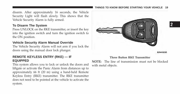
To Disarm The SystemPress UNLOCK on the RKE transmitter, or insert the keyinto the ignition switch and turn the ignition switch tothe ON position.
Vehicle Security Alarm Manual OverrideThe Vehicle Security Alarm will not arm if you lock thedoors using the manual door lock plunger.
REMOTE KEYLESS ENTRY (RKE) — IFEQUIPPEDThis system allows you to lock or unlock the doors andliftgate or activate the Panic Alarm from distances up toapproximately 66 ft (20 m) using a hand-held RemoteKeyless Entry (RKE) transmitter. The RKE transmitterdoes not need to be pointed at the vehicle to activate thesystem.
NOTE: The line of transmission must not be blockedwith metal objects.
Three Button RKE Transmitter
2
THINGS TO KNOW BEFORE STARTING YOUR VEHICLE 19
To Unlock The Doors And LiftgatePress and release the UNLOCK button on the RKEtransmitter once to unlock the driver’s door, or twicewithin five seconds to unlock all doors and liftgate. Theturn signal lights will flash to acknowledge the unlocksignal. The illuminated entry system will also turn on.
Remote Key Unlock, Driver Door/All First PressThis feature lets you program the system to unlock eitherthe driver’s door or all doors on the first press of theUNLOCK button on the RKE transmitter. To change thecurrent setting, proceed as follows:
• For vehicles equipped with the Electronic VehicleInformation Center (EVIC), refer to “Electronic VehicleInformation Center (EVIC)/Personal Settings (Cus-tomer-Programmable Features)” in “UnderstandingYour Instrument Panel” for further information.
• For vehicles not equipped with the EVIC, perform thefollowing steps:
1. Press and hold the LOCK button on a programmedRKE transmitter for at least 4 seconds, but no longer than10 seconds. Then, press and hold the UNLOCK buttonwhile still holding the LOCK button.
2. Release both buttons at the same time.
3. Test the feature while outside of the vehicle by press-ing the LOCK/UNLOCK buttons on the RKE transmitterwith the ignition switch in the LOCK position and thekey removed.
4. Repeat these steps if you want to return this feature toits previous setting.
NOTE: Pressing the LOCK button on the RKE transmit-ter while you are inside the vehicle will activate theVehicle Security Alarm. Opening a door with the Vehicle
20 THINGS TO KNOW BEFORE STARTING YOUR VEHICLE
Security Alarm activated will cause the alarm to sound.Press the UNLOCK button to deactivate the VehicleSecurity Alarm.
Illuminated Approach — If EquippedThis feature activates the headlights for up to 90 secondswhen the doors are unlocked with the RKE transmitter.The time for this feature is programmable on vehiclesequipped with the EVIC. Refer to “Electronic VehicleInformation Center (EVIC)/Personal Settings (Customer-Programmable Features)” in “Understanding Your In-strument Panel” for further information.
To Lock The Doors And LiftgatePress and release the LOCK button on the RKE transmit-ter to lock all doors and liftgate. The turn signal lightswill flash and the horn will chirp to acknowledge thesignal.
Sound Horn With Remote Key Lock
This feature will cause the horn to chirp when the doorsare locked with the RKE transmitter. This feature can beturned on or turned off. To change the current setting,proceed as follows:
• For vehicles equipped with the EVIC, refer to “Elec-tronic Vehicle Information Center (EVIC)/PersonalSettings (Customer-Programmable Features)” in “Un-derstanding Your Instrument Panel” for further infor-mation.
• For vehicles not equipped with the EVIC, perform thefollowing steps:
1. Press the LOCK button on a programmed RKE trans-mitter for at least 4 seconds, but no longer than 10 sec-onds. Then, press the PANIC button while still holdingthe LOCK button.
2. Release both buttons at the same time.
2
THINGS TO KNOW BEFORE STARTING YOUR VEHICLE 21
3. Test the feature while outside of the vehicle by press-ing the LOCK button on the RKE transmitter with theignition switch in the LOCK position and the key re-moved.
4. Repeat these steps if you want to return this feature toits previous setting.
NOTE: Pressing the LOCK button on the RKE transmit-ter while you are in the vehicle will activate the VehicleSecurity Alarm. Opening a door with the Vehicle SecurityAlarm activated will cause the alarm to sound. Press theUNLOCK button to deactivate the Vehicle SecurityAlarm.
Flash Lights With Remote Key Lock/Unlock
This feature will cause the turn signal lights to flash whenthe doors are locked or unlocked with the RKE transmit-ter. This feature can be turned on or turned off. To changethe current setting, proceed as follows:
• For vehicles equipped with the EVIC, refer to “Elec-tronic Vehicle Information Center (EVIC)/PersonalSettings (Customer-Programmable Features)” in “Un-derstanding Your Instrument Panel” for further infor-mation.
• For vehicles not equipped with the EVIC, perform thefollowing steps:
1. Press and hold the UNLOCK button on a programmedRKE transmitter for at least 4 seconds, but no longer than10 seconds. Then, press and hold the LOCK button whilestill holding the UNLOCK button.
2. Release both buttons at the same time.
22 THINGS TO KNOW BEFORE STARTING YOUR VEHICLE
3. Test the feature while outside of the vehicle by press-ing the LOCK/UNLOCK buttons on the RKE transmitterwith the ignition switch in the LOCK position and thekey removed.
4. Repeat these steps if you want to return this feature toits previous setting.
NOTE: Pressing the LOCK button on the RKE transmit-ter while you are in the vehicle will activate the VehicleSecurity Alarm. Opening a door with the Vehicle SecurityAlarm activated will cause the alarm to sound. Press theUNLOCK button to deactivate the Vehicle SecurityAlarm.
Using The Panic AlarmTo turn the Panic Alarm feature ON or OFF, press andhold the PANIC button on the RKE transmitter for atleast one second and release. When the Panic Alarm is on,the headlights and park lights will flash, the horn willpulse on and off and the interior lights will turn on.
The Panic Alarm will stay on for three minutes unlessyou turn it off by pressing the PANIC button a secondtime or if the vehicle speed is 5 mph (8 km/h) or greater.
NOTE: When you turn off the Panic Alarm by pressingthe PANIC button a second time, you may have to becloser to the vehicle due to the radio frequency noises ofthe system.
Programming Additional TransmittersRefer to Sentry Key� “Customer Key Programming.”
If you do not have a programmed RKE transmitter,contact your authorized dealer for details.
General InformationThis device complies with Part 15 of FCC rules and withRS-210 of Industry Canada. Operation is subject to thefollowing conditions:
1. This device may not cause harmful interference.
2
THINGS TO KNOW BEFORE STARTING YOUR VEHICLE 23

2. This device must accept any interference that may bereceived including interference that may cause undesiredoperation.
NOTE: Changes or modifications not expressly ap-proved by the party responsible for compliance couldvoid the user’s authority to operate the equipment.
If your RKE transmitter fails to operate from a normaldistance, check for these two conditions:
1. Weak battery in the RKE transmitter. The expected lifeof battery is five years.
2. Closeness to a radio transmitter such as a radio stationtower, airport transmitter, military base, and some mobileor CB radios.
Transmitter Battery Replacement
NOTE: Perchlorate Material – special handling may ap-ply. See “www.dtsc.ca.gov/hazardouswaste/perchlorate.”
The recommended replacement battery is CR2032.
1. If the RKE transmitter is equipped with a screw,remove the screw. With the RKE transmitter buttonsfacing down, use a flat blade to pry the two halves of theRKE transmitter apart. Make sure not to damage theelastomer seal during removal.
Separating RKE Transmitter Halves
24 THINGS TO KNOW BEFORE STARTING YOUR VEHICLE

2. Remove and replace the battery. Avoid touching thenew battery with your fingers. Skin oils may causebattery deterioration. If you touch a battery, clean it withrubbing alcohol.
3. To reassemble the RKE transmitter case, snap the twohalves together.
NOTE: If the RKE transmitter is equipped with a screw,reinstall and tighten the screw until snug.
REMOTE STARTING SYSTEM — IF EQUIPPEDThis system uses the Remote Keyless Entry(RKE) transmitter to start the engine conve-niently from outside the vehicle while stillmaintaining security. The system has a range of
approximately 328 ft (100 m).
NOTE: The vehicle must be equipped with an auto-matic transmission to be equipped with Remote Start.
How to Use Remote StartAll of the following conditions must be met before theengine will remote start:
• Shift lever in PARK
• Doors closed
• Hood closed
• Hazard switch off
• Brake switch inactive (brake pedal not pressed)
• Ignition key removed from ignition switch
• Battery at an acceptable charge level
• RKE PANIC button not pressed
2
THINGS TO KNOW BEFORE STARTING YOUR VEHICLE 25
WARNING!
• Do not start or run an engine in a closed garage orconfined area. Exhaust gas contains Carbon Mon-oxide (CO) which is odorless and colorless. Car-bon Monoxide is poisonous and can cause seriousinjury or death when inhaled.
• Keep Remote Keyless Entry (RKE) transmittersaway from children. Operation of the Remote StartSystem, windows, door locks or other controlscould cause serious injury or death.
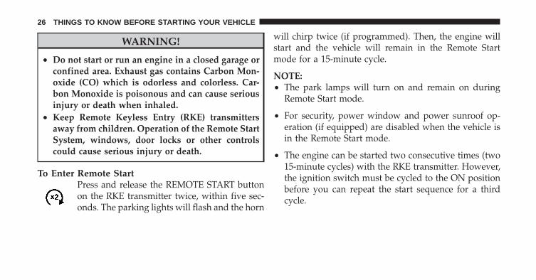
To Enter Remote StartPress and release the REMOTE START buttonon the RKE transmitter twice, within five sec-onds. The parking lights will flash and the horn
will chirp twice (if programmed). Then, the engine willstart and the vehicle will remain in the Remote Startmode for a 15-minute cycle.
NOTE:• The park lamps will turn on and remain on during
Remote Start mode.
• For security, power window and power sunroof op-eration (if equipped) are disabled when the vehicle isin the Remote Start mode.
• The engine can be started two consecutive times (two15-minute cycles) with the RKE transmitter. However,the ignition switch must be cycled to the ON positionbefore you can repeat the start sequence for a thirdcycle.
26 THINGS TO KNOW BEFORE STARTING YOUR VEHICLE

Remote start will also cancel if any of the following occur:
• The engine stalls or RPM exceeds 2500
• Any engine warning lamps come on
• The hood is opened
• The hazard switch is pressed
• The transmission is moved out of PARK
• The brake pedal is pressed
To Exit Remote Start Mode without Driving theVehiclePress and release the REMOTE START button one time,or allow the engine to run for the entire 15-minute cycle.
NOTE: To avoid unintentional shut downs, the systemwill disable the one time press of the REMOTE STARTbutton for two seconds after receiving a valid RemoteStart request.
To Exit Remote Start Mode and Drive the VehicleBefore the end of the 15-minute cycle, press and releasethe UNLOCK button on the RKE transmitter to unlockthe doors and disarm the Vehicle Security Alarm (ifequipped). Then, insert the key into the ignition switchand turn the switch to the ON position.
NOTE: The ignition switch must be in the ON positionin order to drive the vehicle.
2
THINGS TO KNOW BEFORE STARTING YOUR VEHICLE 27

DOOR LOCKS
Manual Door LocksUse the manual door lock plunger to lock the doors frominside the vehicle. If the plunger is down when the dooris closed, the door will lock. Make sure the keys are notinside the vehicle before closing the door.
WARNING!
• For personal security and safety in the event of anaccident, lock the vehicle doors as you drive aswell as when you park and leave the vehicle.
• When leaving the vehicle, always remove the keyfrom the ignition lock and lock your vehicle. Donot leave unattended children in the vehicle orwith access to an unlocked vehicle. Unsuperviseduse of vehicle equipment may cause severe per-sonal injuries and death.
CAUTION!
An unlocked vehicle is an invitation to thieves.Always remove the key from the ignition and lock allof the doors when leaving the vehicle unattended.
Manual Door Lock Plunger
28 THINGS TO KNOW BEFORE STARTING YOUR VEHICLE
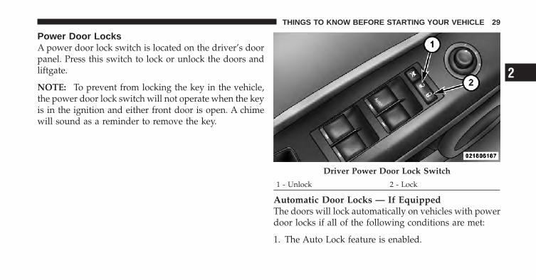
Power Door LocksA power door lock switch is located on the driver’s doorpanel. Press this switch to lock or unlock the doors andliftgate.
NOTE: To prevent from locking the key in the vehicle,the power door lock switch will not operate when the keyis in the ignition and either front door is open. A chimewill sound as a reminder to remove the key.
Automatic Door Locks — If EquippedThe doors will lock automatically on vehicles with powerdoor locks if all of the following conditions are met:
1. The Auto Lock feature is enabled.
Driver Power Door Lock Switch
1 - Unlock 2 - Lock
2
THINGS TO KNOW BEFORE STARTING YOUR VEHICLE 29

2. The transmission is in gear.
3. All doors are closed.
4. The throttle is pressed.
5. The vehicle speed is above 15 mph (24 km/h).
6. The doors were not previously locked using the powerdoor lock switch or Remote Keyless Entry (RKE)transmitter.
Automatic Door Locks ProgrammingThe Automatic Door Locks feature can be enabled ordisabled as follows:
• For vehicles equipped with the Electronic VehicleInformation Center (EVIC), refer to “Electronic VehicleInformation Center (EVIC) — If Equipped/PersonalSettings (Customer-Programmable Features)” in “Un-derstanding Your Instrument Panel” for further infor-mation.
• For vehicles not equipped with the EVIC, perform thefollowing procedure:
1. Close all doors and place the key in the ignitionswitch.
2. Within 15 seconds, cycle the ignition switch betweenLOCK and ON and then back to LOCK four times endingup in the LOCK position (do not start the engine).
3. Within 30 seconds, press the power door LOCK switchto lock the doors.
4. A single chime will indicate the completion of theprogramming.
5. Repeat these steps if you want to return this feature toits previous setting.
30 THINGS TO KNOW BEFORE STARTING YOUR VEHICLE

NOTE:• If you do not hear the chime it means that the system
did not enter the programming mode and you willneed to repeat the procedure.
• Use the Automatic Door Locks feature in accordancewith local laws.
Automatic Unlock Doors on ExitThe doors will unlock automatically if:
1. The Automatic Unlock Doors On Exit feature is en-abled.
2. The transmission was in gear and the vehicle speedreturned to 0 mph (0 km/h).
3. The transmission is in NEUTRAL or PARK.
4. The driver’s door is opened.
5. The doors were not previously unlocked.
Automatic Unlock Doors on Exit ProgrammingThe Automatic Unlock Doors On Exit feature can beenabled or disabled as follows:
• For vehicles equipped with the EVIC, refer to “Elec-tronic Vehicle Information Center (EVIC) — IfEquipped/Personal Settings (Customer-Program-mable Features)” in “Understanding Your InstrumentPanel” for further information.
• For vehicles not equipped with the EVIC, perform thefollowing procedure:
1. Close all doors and place the key in the ignition.
2. Within 15 seconds, cycle the ignition switch betweenLOCK and ON and then back to LOCK four times endingup in the LOCK position (do not start the engine).
3. Within 30 seconds, press the power door UNLOCKswitch to unlock the doors.
2
THINGS TO KNOW BEFORE STARTING YOUR VEHICLE 31

4. A single chime will indicate the completion of theprogramming.
5. Repeat these steps if you want to return this feature toits previous setting.
NOTE:• If you do not hear the chime it means that the system
did not enter the programming mode and you willneed to repeat the procedure.
• Use the Automatic Unlock Doors On Exit feature inaccordance with local laws.
Child-Protection Door Lock System (Rear Doors)Insert the tip of the ignition key into the lock and rotateto the LOCK or UNLOCK position.
Child-Protection Door Lock Location
32 THINGS TO KNOW BEFORE STARTING YOUR VEHICLE

WARNING!
Avoid trapping anyone in a vehicle in a collision.Remember that the rear doors can only be openedfrom the outside when the child protection locks areengaged.
NOTE: For emergency exit with the system engaged,move the lock plunger up (unlocked position), roll downthe window and open the door with the outside doorhandle.
POWER WINDOWS — IF EQUIPPED
Power Window SwitchesThe window controls on the driver’s door trim panelcontrol all the door windows. There are single windowcontrols on each passenger door trim panel, which oper-ate the passenger door windows. The window controlswill operate when the ignition switch is in the ON orACC position.
NOTE:• For vehicles not equipped with the Electronic Vehicle
Information Center (EVIC), the power windowswitches will remain active for 45 seconds after theignition switch is turned to the LOCK position. Open-ing either front door will cancel this feature.
Child-Protection Door Lock Function
2
THINGS TO KNOW BEFORE STARTING YOUR VEHICLE 33

• For vehicles equipped with the EVIC, the powerwindow switches will remain active for up to 10 min-utes after the ignition switch is turned to the LOCKposition. Opening either front door will cancel thisfeature. The time for this feature is programmable.Refer to “Electronic Vehicle Information Center(EVIC)/Personal Settings (Customer-ProgrammableFeatures)” in “Understanding Your Instrument Panel”for further information.
WARNING!
Never leave children in a vehicle with the key in theignition switch. Occupants, particularly unattendedchildren, can become entrapped by the windowswhile operating the power window switches. Suchentrapment may result in serious injury or death.
Auto-DownThe driver’s door window switch has an Auto-Downfeature. Push the window switch past the first detent,release, and the window will go down automatically. Tocancel the Auto-Down movement, operate the switch ineither the up or down direction and release the switch.
Power Window Switch Location
34 THINGS TO KNOW BEFORE STARTING YOUR VEHICLE

Window Lockout SwitchThe window lockout switch on the driver’s door allowsyou to disable the window control on the other doors. Todisable the window controls on the other doors, press thewindow LOCKOUT switch. To enable the window con-trols, press the window LOCKOUT switch a second time.
LIFTGATE
NOTE: The key that is used to start the vehicle is alsoused to lock or unlock the doors and open the liftgate.
To unlock the liftgate, insert the key into the lock andturn it to the right (manual lock models only). The liftgatecan also be unlocked using the Remote Keyless Entry(RKE) transmitter or by activating the power door lockswitches located on the front doors. The central locking/unlocking feature (if equipped) can also be activatedfrom the liftgate key cylinder.
Window Lockout Switch
2
THINGS TO KNOW BEFORE STARTING YOUR VEHICLE 35
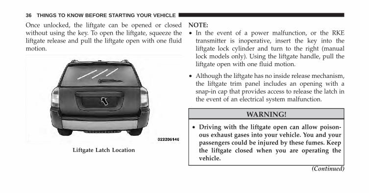
Once unlocked, the liftgate can be opened or closedwithout using the key. To open the liftgate, squeeze theliftgate release and pull the liftgate open with one fluidmotion.
NOTE:• In the event of a power malfunction, or the RKE
transmitter is inoperative, insert the key into theliftgate lock cylinder and turn to the right (manuallock models only). Using the liftgate handle, pull theliftgate open with one fluid motion.
• Although the liftgate has no inside release mechanism,the liftgate trim panel includes an opening with asnap-in cap that provides access to release the latch inthe event of an electrical system malfunction.
WARNING!
• Driving with the liftgate open can allow poison-ous exhaust gases into your vehicle. You and yourpassengers could be injured by these fumes. Keepthe liftgate closed when you are operating thevehicle.
(Continued)
Liftgate Latch Location
36 THINGS TO KNOW BEFORE STARTING YOUR VEHICLE

WARNING! (Continued)• If you are required to drive with the liftgate open,
make sure that all windows are closed, and theclimate control blower switch is set at high speed.DO NOT use the recirculation mode.
Gas props support the liftgate in the open position.However, because the gas pressure drops with tempera-ture, it may be necessary to assist the props whenopening the liftgate in cold weather.
OCCUPANT RESTRAINTSSome of the most important safety features in yourvehicle are the restraint systems:
• Three-point lap and shoulder belts for all seatingpositions
• Advanced Front Airbags for driver and front passen-ger
• Supplemental Rear Impact Active Head Restraints(AHR) located on top of the front seats (integrated intothe head restraint)
• Supplemental Side Airbag Inflatable Curtains (SABIC)for the driver and passengers seated next to a window
• Supplemental Side Seat Airbags — if equipped
• An energy-absorbing steering column and steeringwheel
• Knee bolsters/blockers for front seat occupants
• Front seat belts incorporate pretensioners to enhanceoccupant protection by managing occupant energyduring an impact event — if equipped
• All seat belt systems (except the driver’s) includeAutomatic Locking Retractors (ALRs), which lock theseat belt webbing into position by extending the belt
2
THINGS TO KNOW BEFORE STARTING YOUR VEHICLE 37
all the way out and then adjusting the belt to thedesired length to restrain a child seat or secure a largeitem in a seat — if equipped
If you will be carrying children too small for adult-sizedseat belts, the seat belts or the Lower Anchors and Tetherfor CHildren (LATCH) feature also can be used to holdinfant and child restraint systems. For more informationon LATCH, see Lower Anchors and Tether for CHildren(LATCH).
NOTE: The Advanced Front Airbags have a multistageinflator design. This allows the airbag to have differentrates of inflation based on severity and type of collision.
Please pay close attention to the information in thissection. It tells you how to use your restraint systemproperly, to keep you and your passengers as safe aspossible.
WARNING!
In a collision, you and your passengers can suffermuch greater injuries if you are not properly buckledup. You can strike the interior of your vehicle or otherpassengers, or you can be thrown out of the vehicle.Always be sure you and others in your vehicle arebuckled up properly.
Buckle up even though you are an excellent driver, evenon short trips. Someone on the road may be a poor driverand cause a collision that includes you. This can happenfar away from home or on your own street.
Research has shown that seat belts save lives, and theycan reduce the seriousness of injuries in a collision. Someof the worst injuries happen when people are thrownfrom the vehicle. Seat belts reduce the possibility of
38 THINGS TO KNOW BEFORE STARTING YOUR VEHICLE
ejection and the risk of injury caused by striking theinside of the vehicle. Everyone in a motor vehicle shouldbe belted at all times.
Lap/Shoulder BeltsAll the seats in your vehicle are equipped with Lap/Shoulder belts.
The belt webbing retractor is designed to lock duringvery sudden stops or collisions. This feature allows theshoulder part of the belt to move freely with you undernormal conditions. But in a collision, the belt will lockand reduce the risk of you striking the inside of thevehicle or being thrown out.
WARNING!
• It is extremely dangerous to ride in a cargo area,inside or outside of a vehicle. In a collision, peopleriding in these areas are more likely to be seri-ously injured or killed.
• Do not allow people to ride in any area of yourvehicle that is not equipped with seats and seatbelts.
• Be sure everyone in your vehicle is in a seat andusing a seat belt properly.
• Wearing a seat belt incorrectly is dangerous. Seatbelts are designed to go around the large bones ofyour body. These are the strongest parts of yourbody and can take the forces of a collision the best.
(Continued)
2
THINGS TO KNOW BEFORE STARTING YOUR VEHICLE 39

WARNING! (Continued)• Wearing your belt in the wrong place could make
your injuries in a collision much worse. You mightsuffer internal injuries, or you could even slide outof part of the belt. Follow these instructions towear your seat belt safely and to keep your pas-sengers safe, too.
• Two people should never be belted into a singleseat belt. People belted together can crash into oneanother in an accident, hurting one another badly.Never use a lap/shoulder belt or lap belt for morethan one person, no matter what their size.
Lap/Shoulder Belt Operating Instructions
1. Enter the vehicle and close the door. Sit back andadjust the seat.
2. The seat belt latch plate is along side the pillar near theback of your seat. Grasp the latch plate and pull out thebelt. Slide the latch plate up the webbing as far asnecessary to allow the belt to go around your lap.
3. When the belt is long enough to fit, insert the latchplate into the buckle until you hear a “click.”
Pulling Out The Latch Plate
40 THINGS TO KNOW BEFORE STARTING YOUR VEHICLE

WARNING!
• A belt that is buckled into the wrong buckle willnot protect you properly. The lap portion couldride too high on your body, possibly causinginternal injuries. Always buckle your belt into thebuckle nearest you.
• A belt that is too loose will not protect you as well.In a sudden stop you could move too far forward,increasing the possibility of injury. Wear your seatbelt snugly.
(Continued)Inserting Latch Plate Into Buckle
2
THINGS TO KNOW BEFORE STARTING YOUR VEHICLE 41

WARNING! (Continued)• A belt that is worn under your arm is very danger-
ous. Your body could strike the inside surfaces ofthe vehicle in a collision, increasing head and neckinjury. A belt worn under the arm can causeinternal injuries. Ribs aren’t as strong as shoulderbones. Wear the belt over your shoulder so thatyour strongest bones will take the force in acollision.
• A shoulder belt placed behind you will not protectyou from injury during a collision. You are morelikely to hit your head in a collision if you do notwear your shoulder belt. The lap and shoulder beltare meant to be used together.
4. Position the lap belt across your thighs, below yourabdomen. To remove slack in the lap belt portion, pull upon the shoulder belt. To loosen the lap belt if it is too tight,tilt the latch plate and pull on the lap belt. A snug beltreduces the risk of sliding under the belt in a collision.
Positioning Lap Belt
42 THINGS TO KNOW BEFORE STARTING YOUR VEHICLE

WARNING!
• A lap belt worn too high can increase the risk ofinternal injury in a collision. The belt forces won’tbe at the strong hip and pelvic bones, but acrossyour abdomen. Always wear the lap belt as low aspossible and keep it snug.
• A twisted belt can’t do its job as well. In acollision, it could even cut into you. Be sure thebelt is straight. If you can’t straighten a belt inyour vehicle, take it to your authorized dealer andhave it fixed.
5. Position the shoulder belt on your chest so that it iscomfortable and not resting on your neck. The retractorwill withdraw any slack in the belt.
6. To release the belt, push the red button on the buckle.The belt will automatically retract to its stowed position.If necessary, slide the latch plate down the webbing toallow the belt to retract fully.
WARNING!
A frayed or torn belt could rip apart in a collision andleave you with no protection. Inspect the belt systemperiodically, checking for cuts, frays, or loose parts.Damaged parts must be replaced immediately. Donot disassemble or modify the system. Seat beltassemblies must be replaced after a collision if theyhave been damaged (bent retractor, torn webbing,etc.).
2
THINGS TO KNOW BEFORE STARTING YOUR VEHICLE 43

Adjustable Upper Shoulder Belt AnchorageIn the front seat, the shoulder belt can be adjustedupward or downward to position the belt away fromyour neck. Push the anchorage button to release theanchorage, and move it up or down to the position thatfits you best.
NOTE: The adjustable upper shoulder belt anchorage isequipped with an Easy Up feature. This feature allowsthe shoulder belt anchorage to be adjusted in the upwardposition without pressing the release button. To verifythe shoulder belt anchorage is latched, pull downwardon the shoulder belt anchorage until it is locked intoposition. As a guide, if you are shorter than average you will
prefer a lower position, and if you are taller than averageyou will prefer a higher position. When you release theanchorage, try to move it down to make sure that it islocked in position.
Adjustable Anchorage
44 THINGS TO KNOW BEFORE STARTING YOUR VEHICLE

In the rear seat, move toward the center of the seat toposition the belt away from your neck.
Second Row Center Lap/Shoulder Belt OperatingInstructionsThe second row center lap/shoulder belt features athree-point seat belt with a mini-latch and buckle, whichallows the shoulder belt to detach from the lower anchorwhen the seat is folded. The mini-buckle and shoulderbelt can then be stored out of the way in the right sidetrim panel for added convenience.
1. Remove the mini-latch and regular latch from itsstowed position in the right rear side trim panel.
2. Grasp the mini-latch plate and pull the belt over theseat.
Mini-Latch Stowage
2
THINGS TO KNOW BEFORE STARTING YOUR VEHICLE 45
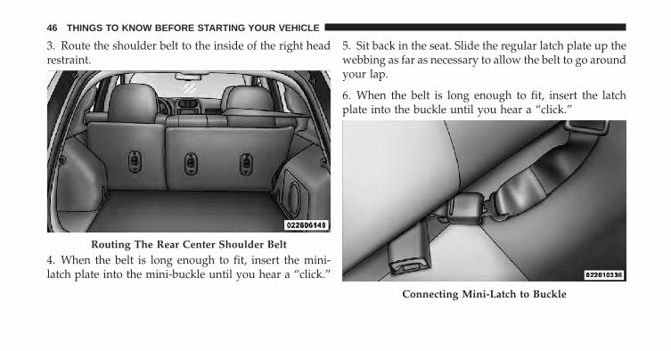
3. Route the shoulder belt to the inside of the right headrestraint.
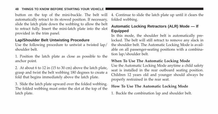
4. When the belt is long enough to fit, insert the mini-latch plate into the mini-buckle until you hear a “click.”
5. Sit back in the seat. Slide the regular latch plate up thewebbing as far as necessary to allow the belt to go aroundyour lap.
6. When the belt is long enough to fit, insert the latchplate into the buckle until you hear a “click.”
Routing The Rear Center Shoulder Belt
Connecting Mini-Latch to Buckle
46 THINGS TO KNOW BEFORE STARTING YOUR VEHICLE

7. Position the lap belt across your thighs, below yourabdomen. To remove slack in the lap belt portion, pull upon the shoulder belt. To loosen the lap belt if it is too tight,pull on the lap belt. A snug belt reduces the risk of slidingunder the belt in a collision.
8. Position the shoulder belt on your chest so that it iscomfortable and not resting on your neck. The retractorwill withdraw any slack in the belt.
9. To release the belt, push the red button on the buckle.
10. To disengage the mini-latch from the mini-buckle forstorage, insert the regular latch plate into the black
Rear Center Seat Belt BuckledDetaching Mini-Latch And Buckle
2
THINGS TO KNOW BEFORE STARTING YOUR VEHICLE 47
button on the top of the mini-buckle. The belt willautomatically retract to its stowed position. If necessary,slide the latch plate down the webbing to allow the beltto retract fully. Insert the mini-latch plate into the slotprovided in the trim panel.
Lap/Shoulder Belt Untwisting ProcedureUse the following procedure to untwist a twisted lap/shoulder belt.
1. Position the latch plate as close as possible to theanchor point.
2. At about 6 to 12 in (15 to 30 cm) above the latch plate,grasp and twist the belt webbing 180 degrees to create afold that begins immediately above the latch plate.
3. Slide the latch plate upward over the folded webbing.The folded webbing must enter the slot at the top of thelatch plate.
4. Continue to slide the latch plate up until it clears thefolded webbing.
Automatic Locking Retractors (ALR) Mode — IfEquippedIn this mode, the shoulder belt is automatically pre-locked. The belt will still retract to remove any slack inthe shoulder belt. The Automatic Locking Mode is avail-able on all passenger-seating positions with a combina-tion lap/shoulder belt.
When To Use The Automatic Locking ModeUse the Automatic Locking Mode anytime a child safetyseat is installed in the rear outboard seating position.Children 12 years old and younger should always beproperly restrained in the rear seat.
How To Use The Automatic Locking Mode
1. Buckle the combination lap and shoulder belt.
48 THINGS TO KNOW BEFORE STARTING YOUR VEHICLE
2. Grasp the shoulder portion and pull downward untilthe entire belt is extracted.
3. Allow the belt to retract. As the belt retracts, you willhear a clicking sound. This indicates the safety belt isnow in the Automatic Locking Mode.
How to Disengage The Automatic Locking ModeDisconnect the combination lap/shoulder belt from thebuckle and allow it to retract completely to disengage theAutomatic Locking Mode and activate the vehicle sensi-tive (emergency) locking mode.
Seat Belt Pretensioners — If EquippedThe seat belts for both front seating positions may beequipped with pretensioning devices that are designed toremove slack from the seat belt in the event of a collision.These devices improve the performance of the seat beltby assuring that the belt is tight about the occupant earlyin a collision. Pretensioners work for all size occupants,including those in child restraints.
NOTE: These devices are not a substitute for proper seatbelt placement by the occupant. The seat belt still must beworn snugly and positioned properly.
The pretensioners are triggered by the Occupant Re-straint Controller (ORC). Like the airbags, the pretension-ers are single use items. After a collision deploys theairbags and/or pretensioners, a deployed airbag and/orpretensioner must be replaced immediately.
Supplemental Rear Impact Active Head Restraints(AHR)These head restraints are passive, deployable compo-nents, and vehicles with this equipment can not bereadily identified by any markings, only through visualinspection of the head restraint. The head restraint will besplit in two halves, with the front half being soft foamand trim, the back half being decorative plastic.
2
THINGS TO KNOW BEFORE STARTING YOUR VEHICLE 49
How the Active Head Restraints (AHR) WorkThe Occupant Restraint Controller (ORC) determineswhether the severity or type of rear impact require theActive Head Restraints (AHR) to deploy. In case of AHRdeployment both driver and front passenger seat AHR’swill be deployed.
When AHR’s deploy during a rear impact, the headrestraint front half extends forward to minimize the gapbetween the back of the head and the AHR. This systemis designed to help prevent or reduce the extent ofinjuries the driver and front passenger in certain types ofrear end impacts.
NOTE: The Active Head Restraints (AHR) may or maynot deploy in the event of a front or side impact.However if during a front impact, a secondary rearimpact occurs, the AHR may deploy based on the sever-ity and type of the impact.
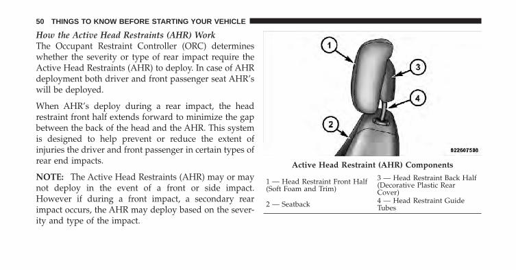
Active Head Restraint (AHR) Components
1 — Head Restraint Front Half(Soft Foam and Trim)
3 — Head Restraint Back Half(Decorative Plastic RearCover)
2 — Seatback 4 — Head Restraint GuideTubes
50 THINGS TO KNOW BEFORE STARTING YOUR VEHICLE
CAUTION!
All occupants, including the driver, should not oper-ate a vehicle or sit in a vehicle’s seat until the headrestraints are placed in their proper positions in orderto minimize the risk of neck injury in the event of anaccident.
NOTE: For more information on properly adjusting andpositioning the head restraint, refer to “Adjusting ActiveHead Restraints” in “Understanding The Features OfYour Vehicle”.
Resetting Active Head Restraints (AHR)If the Active Head Restraints are triggered in an accident,you must reset the head restraint on the driver’s andfront passenger seat. You can recognize when the ActiveHead Restraint has been triggered by the fact that theyhave moved forward (as shown in step three of theresetting procedure).
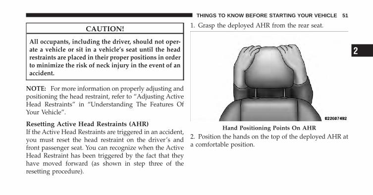
1. Grasp the deployed AHR from the rear seat.
2. Position the hands on the top of the deployed AHR ata comfortable position.
Hand Positioning Points On AHR
2
THINGS TO KNOW BEFORE STARTING YOUR VEHICLE 51

3. Pull down then rearward towards the rear of thevehicle then down to engage the locking mechanism.
4. The AHR front soft foam and trim half should lockinto the back decorative plastic half.
1 — Downward Movement2 — Rearward Movement
3 — Final Downward Movement To Engage Locking Mecha-nism
52 THINGS TO KNOW BEFORE STARTING YOUR VEHICLE
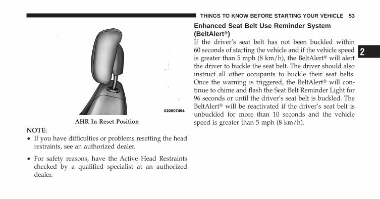
NOTE:• If you have difficulties or problems resetting the head
restraints, see an authorized dealer.
• For safety reasons, have the Active Head Restraintschecked by a qualified specialist at an authorizeddealer.
Enhanced Seat Belt Use Reminder System(BeltAlert�)If the driver’s seat belt has not been buckled within60 seconds of starting the vehicle and if the vehicle speedis greater than 5 mph (8 km/h), the BeltAlert� will alertthe driver to buckle the seat belt. The driver should alsoinstruct all other occupants to buckle their seat belts.Once the warning is triggered, the BeltAlert� will con-tinue to chime and flash the Seat Belt Reminder Light for96 seconds or until the driver’s seat belt is buckled. TheBeltAlert� will be reactivated if the driver’s seat belt isunbuckled for more than 10 seconds and the vehiclespeed is greater than 5 mph (8 km/h).AHR In Reset Position
2
THINGS TO KNOW BEFORE STARTING YOUR VEHICLE 53
BeltAlert� ProgrammingBeltAlert� can be enabled or disabled by your authorizeddealer or by performing the following procedure:
NOTE: The following steps must occur within the first60 seconds of the ignition switch being turned to the ONor START position. Chrysler Group LLC does not recom-mend deactivating BeltAlert�.
1. Turn the ignition switch to the LOCK position andbuckle the driver’s seat belt.
2. Turn the ignition switch to the ON position and waitfor the Seat Belt Reminder Light to turn off.
3. Unbuckle and then re-buckle the driver’s seat belt atleast three times within 10 seconds, ending with the seatbelt buckled.
NOTE: Watch for the Seat Belt Reminder Light to turnon while unbuckling and off while re-buckling the seatbelt. It may be necessary to retract the seat belt.
4. Turn the ignition switch to the LOCK position. Asingle chime will sound to signify that you have success-fully completed the programming.
BeltAlert� can be reactivated by repeating this procedure.
NOTE: Although BeltAlert� has been deactivated, theSeat Belt Reminder Light will continue to illuminatewhile the driver’s seat belt remains unbuckled.
54 THINGS TO KNOW BEFORE STARTING YOUR VEHICLE

Seat Belt ExtenderIf a seat belt is too short, even when fully extended, andwhen the adjustable upper shoulder belt anchorage (ifequipped) is in its lowest position, your authorizeddealer can provide you with a seat belt extender. Thisextender should be used only if the existing belt is notlong enough. When it is not required, remove the ex-tender and store it.
WARNING!
Using a seat belt extender when not needed canincrease the risk of injury in a collision. Only usewhen the seat belt is not long enough when it is wornlow and snug, and in the recommended seatingpositions. Remove and store the extender when notneeded.
Seat Belts And Pregnant WomenWe recommend that pregnant women use the seat beltsthroughout their pregnancy. Keeping the mother safe isthe best way to keep the baby safe.
Pregnant women should wear the lap part of the beltacross the thighs and as snug across the hips as possible.Keep the belt low so that it does not come across theabdomen. That way the strong bones of the hips will takethe force if there is a collision.
2
THINGS TO KNOW BEFORE STARTING YOUR VEHICLE 55

Supplemental Restraint System (SRS) - AirbagsThis vehicle has airbags for both the driver and frontpassenger as a supplement to the seat belt restraintsystems. The driver’s front airbag is mounted in thecenter of the steering wheel. The passenger’s front airbagis mounted in the instrument panel, above the glovecompartment. The words SRS AIRBAG are embossed onthe airbag covers.
NOTE: These airbags are certified to the new Federalregulations for Advanced Airbags.
The Advanced Front Airbags have a multistage inflatordesign. This allows the airbag to have different rates ofinflation that are based on the severity and type ofcollision.
Front Airbags and Knee Bolsters
1 — Driver and Passenger Airbag 2 — Knee Boltser
56 THINGS TO KNOW BEFORE STARTING YOUR VEHICLE

This vehicle is equipped with Supplemental Side AirbagInflatable Curtains (SABIC) to protect the driver, front,and rear passengers sitting next to a window. The SABICare located above the side windows. The trim coveringthe side airbags is labeled SRS AIRBAG.
NOTE: Airbag covers may not be obvious in the interiortrim; but they will open during airbag deployment.
Airbag System ComponentsThe airbag system consists of the following:
• Occupant Restraint Controller (ORC)
• Airbag Warning Light
• Driver Front Airbag
• Front Passenger Airbag
• Supplemental Rear Impact Active Head Restraint forDriver and Front Passenger
• Supplemental Side Airbag Inflatable Curtains (SABIC)
• Supplemental Side Seat Airbags — If Equipped
• Front and Side Impact Sensors
• Steering Wheel and Column
• Instrument Panel
• Knee Impact Bolster
• Front Seat Belt Pretensioners — if equipped
2
THINGS TO KNOW BEFORE STARTING YOUR VEHICLE 57

Advanced Front Airbag FeaturesThe Advanced Front Airbag system has multistage driverand front passenger airbags. This system provides outputappropriate to the severity and type of collision asdetermined by the Occupant Restraint Controller (ORC),which may receive information from the impact sensorsat the front of the car.
The first stage inflator is triggered immediately during animpact that requires airbag deployment. The timing ofthe second stage determines whether the output force islow, medium, or high. If a low output is sufficient to meetthe need, the remaining gas in the inflator is expended.
WARNING!
• No objects should be placed over or near theairbag on the instrument panel, because any suchobjects could cause harm if the vehicle is in a crashsevere enough to cause the airbag to inflate.
• Do not put anything on or around the airbag coversor attempt to open them manually. You may dam-age the airbags and you could be injured becausethe airbags may no longer be functional. Theprotective covers for the airbag cushions are de-signed to open only when the airbags are inflating.
• Do not drill, cut or tamper with the knee bolster inany way.
• Do not mount any accessories to the knee bolstersuch as alarm lights, stereos, citizen band radios,etc.
58 THINGS TO KNOW BEFORE STARTING YOUR VEHICLE

Supplemental Side Seat Airbags — If EquippedSupplemental side seat airbags provide enhanced protec-tion and work together with supplemental Side AirbagInflatable Curtains (SABIC) to help protect an occupantduring a side impact. The supplemental side seat airbagis marked with an airbag label sewn into the outboardside of the seat.
When the bag deploys, it opens the seam between thefront and side of the seat’s trim cover. Each bag deploysindependently, that is a left side impact deploys the leftbag only and a right-side impact deploys only the rightbag.
Supplemental Side Seat Airbag Label
2
THINGS TO KNOW BEFORE STARTING YOUR VEHICLE 59

Supplemental Side Airbag Inflatable Curtain(SABIC)SABIC airbags offer side-impact and vehicle rolloverprotection to front and rear seat outboard occupants inaddition to that provided by the body structure. Eachairbag features inflated chambers placed adjacent to thehead of each outboard occupant that reduce the potentialfor side-impact head injuries. The SABIC airbags deploydownward, covering both windows on the impact side.
NOTE:• Should a vehicle rollover occur, the pretensioners
and/or SABIC curtains on both sides of the vehiclemay deploy.
• Airbag covers may not be obvious in the interior trim;but they will open during airbag deployment.
Side Curtain Airbag Label Location
60 THINGS TO KNOW BEFORE STARTING YOUR VEHICLE

The system includes sensors adjacent to both front andrear seat occupants that are calibrated to deploy theSABIC airbags during impacts that require airbag occu-pant protection.
WARNING!
• If your vehicle is equipped with left and right SideAirbag Inflatable Curtain (SABIC), do not stackluggage or other cargo up high enough to blockthe location of the SABIC. The area where the sidecurtain airbag is located should remain free fromany obstructions.
• Do not use accessory seat covers or place objectsbetween you and the side airbags; the performancecould be adversely affected and/or objects couldbe pushed into you, causing serious injury.
Knee Impact BolstersThe Knee Impact Bolsters help protect the knees of thedriver and the front passenger, and position everyone forthe best interaction with the Advanced Front Airbag.
Along with seat belts and pretensioners, Advanced FrontAirbags work with the knee bolsters to provide improvedprotection for the driver and front passenger. Side airbagsalso work with seat belts to improve occupant protection.
Here are some simple steps you can take to minimize therisk of harm from a deploying airbag:
1. Children 12 years old and younger should alwaysride buckled up in a rear seat.
2
THINGS TO KNOW BEFORE STARTING YOUR VEHICLE 61

WARNING!
Infants in rear facing child restraints should NEVERride in the front seat of a vehicle with a passengerfront airbag. An airbag deployment can cause severeinjury or death to infants in that position.
Children that are not big enough to wear the vehicle seatbelt properly (see section on Child Restraints) should besecured in the rear seat in child restraints or belt-positioning booster seats. Older children who do not usechild restraints or belt-positioning booster seats shouldride properly buckled up in the rear seat. Never allowchildren to slide the shoulder belt behind them or undertheir arm.
If a child from 1 to 12 years old (not in a rear facing childseat) must ride in the front passenger seat, move the seatas far back as possible and use the proper child restraint.(Refer to “Child Restraints”)
You should read the instructions provided with yourchild restraint to make sure that you are using it properly.
2. All occupants should ALWAYS wear their lap andshoulder belts properly.
3. The driver and front passenger seats should bemoved back as far as practical to allow the AdvancedFront Airbags room to inflate.
4. Do not lean against the door. If your vehicle has sideairbags, and deployment occurs, the side airbags willinflate forcefully into the space between you and thedoor.
5. If the airbag system in this vehicle needs to bemodified to accommodate a disabled person, contactthe Customer Center. Phone numbers are providedunder �If You Need Assistance�.
62 THINGS TO KNOW BEFORE STARTING YOUR VEHICLE
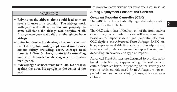
WARNING!
• Relying on the airbags alone could lead to moresevere injuries in a collision. The airbags workwith your seat belt to restrain you properly. Insome collisions, the airbags won’t deploy at all.Always wear your seat belts even though you haveairbags.
• Being too close to the steering wheel or instrumentpanel during front airbag deployment could causeserious injury, including death. Airbags needroom to inflate. Sit back, comfortably extendingyour arms to reach the steering wheel or instru-ment panel.
• Side airbags also need room to inflate. Do not leanagainst the door. Sit upright in the center of theseat.
Airbag Deployment Sensors and Controls
Occupant Restraint Controller (ORC)The ORC is part of a Federally regulated safety systemrequired for this vehicle.
The ORC determines if deployment of the front and/orside airbags in a frontal or side collision is required.Based on the impact sensors signals, a central electronicORC deploys the Advanced Front Airbags, SABIC air-bags, Supplemental Side Seat Airbags — if equipped, andfront seat belt pretensioners — if equipped, as required,depending on severity and type of impact.
Advanced Front Airbags are designed to provide addi-tional protection by supplementing the seat belts incertain frontal collisions depending on the severity andtype of collision. Advanced Front Airbags are not ex-pected to reduce the risk of injury in rear, side, or rollovercollisions.
2
THINGS TO KNOW BEFORE STARTING YOUR VEHICLE 63
The Advanced Front Airbags will not deploy in all frontalcollisions, including some that may produce substantialvehicle damage — for example, some pole collisions,truck underrides, and angle offset collisions. On the otherhand, depending on the type and location of impact,Advanced Front Airbags may deploy in crashes withlittle vehicle front-end damage but that produce a severeinitial deceleration.
The side airbags will not deploy in all side collisions. Sideairbag deployment will depend on the severity and typeof collision.
Because airbag sensors measure vehicle deceleration overtime, vehicle speed and damage by themselves are notgood indicators of whether or not an airbag should havedeployed.
Seat belts are necessary for your protection in all colli-sions, and also are needed to help keep you in position,away from an inflating airbag.
The ORC monitors the readiness of the electronic parts ofthe system whenever the ignition switch is in the STARTor ON position. If the key is in the OFF position, in theACC position, or not in the ignition, the airbags are noton and will not inflate.
The ORC contains a backup power supply system thatmay deploy the airbags even if the battery loses power orit becomes disconnected prior to deployment.
Also, the ORC turns on the Airbag WarningLight in the instrument panel for approxi-mately six to eight seconds for a self-checkwhen the ignition is first turned on. After the
self-check, the Airbag Warning Light will turn off. If theORC detects a malfunction in any part of the system, itturns on the Airbag Warning Light, either momentarilyor continuously. A single chime will sound if the lightcomes on again after initial startup.
64 THINGS TO KNOW BEFORE STARTING YOUR VEHICLE
It also includes diagnostics that will illuminate the instru-ment cluster Airbag Warning Light if a malfunction isnoted. The diagnostics also record the nature of themalfunction.
WARNING!
Ignoring the Airbag Warning Light in your instru-ment panel could mean you won’t have the airbags toprotect you in a collision. If the light does not comeon, stays on after you start the vehicle, or if it comeson as you drive, have the airbag system checked rightaway.
Driver and Passenger Airbag Inflator UnitsThe Driver and Passenger Airbag/Inflator Units arelocated in the center of the steering wheel and the rightside of the instrument panel. When the ORC detects acollision requiring the airbags, it signals the inflator units.A large quantity of non-toxic gas is generated to inflate
the Advanced Front Airbags. Different airbag inflationrates are possible, based on the collision type and sever-ity. The steering wheel hub trim cover and the upperright side of the instrument panel separate and fold outof the way as the bags inflate to their full size. The bagsfully inflate in about 50 to 70 milliseconds. This is abouthalf of the time it takes to blink your eyes. The bags thenquickly deflate while helping to restrain the driver andfront passenger.
The driver front airbag gas is vented through the ventholes in the sides of the airbag. The passenger frontairbag gas is vented through the vent holes in the sides ofthe airbag. In this way, the airbags do not interfere withyour control of the vehicle.
Supplemental Side Seat Airbag Inflator Units — IfEquippedThe Side Impact (SRS) Seat-Mounted Side Airbags aredesigned to activate only in certain side collisions.
2
THINGS TO KNOW BEFORE STARTING YOUR VEHICLE 65
The ORC determines if a side collision requires the sideairbags to inflate based on the severity and type ofcollision.
The ORC monitors the readiness of the electronic parts ofthe system whenever the ignition switch is in the STARTor ON positions. These include all of the items previouslymentioned.
Based on the severity and type of collision, the sideairbag inflator on the crash side of the vehicle may betriggered, releasing a quantity of non-toxic gas. Theinflating side airbag exits through the seat seam into thespace between the occupant and the door. The sideairbags fully inflate in about 10 milliseconds. The sideairbag moves at a very high speed and with such a highforce, that it could injure you if you are not seatedproperly, or if items are positioned in the area where theside airbag inflates. This especially applies to children.
Supplemental Side Airbag Inflatable Curtain(SABIC) Inflator Units — If EquippedDuring collisions where the impact is confined to aparticular area of the side of the vehicle, the ORC maydeploy the SABIC airbags, depending on severity andtype of collision. In these events, the ORC will deploy theSABIC only on the impact side of the vehicle.
A quantity of non-toxic gas is generated to inflate the sidecurtain airbag. The inflating side curtain airbag pushesthe outside edge of the headliner out of the way andcovers the window. The airbag inflates in about 30 ms(about one-quarter of the time that it takes to blink youreyes) with enough force to injure you if you are not beltedand seated properly, or if items are positioned in the areawhere the side curtain airbag inflates. This especiallyapplies to children. The side curtain airbag is only about3-1/2 in (9 cm) thick when it is inflated.
66 THINGS TO KNOW BEFORE STARTING YOUR VEHICLE
Because airbag sensors estimate deceleration over time,vehicle speed and damage are not good indicators ofwhether or not an airbag should have deployed.
NOTE: In a rollover the pretensioners and/or SABICairbags may deploy on both sides of the vehicle.
Front and Side Impact SensorsIn front and side impacts, impact sensors aid the ORC indetermining appropriate response to impact events. Ad-ditional sensors in the ORC determine the level of airbagdeployment and provide verification.
Enhanced Accident Response SystemIn the event of an impact causing airbag deployment, ifthe communication network remains intact, and thepower remains intact, depending on the nature of theevent the ORC will determine whether to have theEnhanced Accident Response System perform the follow-ing functions:
• Cut off fuel to the engine.
• Flash hazard lights as long as the battery has power oruntil the ignition key is turned off.
• Turn on the interior lights, which remain on as long asthe battery has power or until the ignition key isremoved.
• Unlock the doors automatically.
If a Deployment OccursThe airbags are designed to deflate immediately afterdeployment.
NOTE: Front and/or side airbags will not deploy in allcollisions. This does not mean something is wrong withthe airbag system.
2
THINGS TO KNOW BEFORE STARTING YOUR VEHICLE 67
If you do have a collision, which deploys the airbags, anyor all of the following may occur:
• The nylon airbag material may sometimes cause abra-sions and/or skin reddening to the driver and frontpassenger as the airbags deploy and unfold. Theabrasions are similar to friction rope burns or thoseyou might get sliding along a carpet or gymnasiumfloor. They are not caused by contact with chemicals.They are not permanent and normally heal quickly.However, if you haven’t healed significantly within afew days, or if you have any blistering, see your doctorimmediately.
• As the airbags deflate, you may see some smoke-likeparticles. The particles are a normal by-product of theprocess that generates the non-toxic gas used forairbag inflation. These airborne particles may irritatethe skin, eyes, nose, or throat. If you have skin or eyeirritation, rinse the area with cool water. For nose or
throat irritation, move to fresh air. If the irritationcontinues, see your doctor. If these particles settle onyour clothing, follow the garment manufacturer’s in-structions for cleaning.
Do not drive your vehicle after the airbags have de-ployed. If you are involved in another collision, theairbags will not be in place to protect you.
WARNING!
Deployed airbags and seat belt pretensioners cannotprotect you in another collision. Have the airbags,seat belt pretensioners, and the front passenger seatbelt retractor assembly replaced by an authorizeddealer as soon as possible. Also, have the OccupantRestraint Controller System serviced as well.
68 THINGS TO KNOW BEFORE STARTING YOUR VEHICLE
Maintaining Your Airbag System
WARNING!
• Modifications to any part of the airbag systemcould cause it to fail when you need it. You couldbe injured if the airbag system is not there toprotect you. Do not modify the components orwiring, including adding any kind of badges orstickers to the steering wheel hub trim cover or theupper right side of the instrument panel. Do notmodify the front bumper, vehicle body structure,or add aftermarket side steps or running boards.
• It is dangerous to try to repair any part of theairbag system yourself. Be sure to tell anyone whoworks on your vehicle that it has an airbag system.
(Continued)
WARNING! (Continued)• Do not attempt to modify any part of your ad-
vanced airbag system. The airbag may inflateaccidentally or may not function properly if modi-fications are made. Take your vehicle to an autho-rized dealer for any advanced airbag system ser-vice. If your seat including your trim cover andcushion needs to be serviced in any way (includ-ing removal or loosening/tightening of seat attach-ment bolts), take the vehicle to your authorizeddealer. Only manufacturer approved seat accesso-ries may be used. If it is necessary to modify anadvanced airbag system for persons with disabili-ties, contact your authorized dealer.
2
THINGS TO KNOW BEFORE STARTING YOUR VEHICLE 69

Airbag Warning LightYou will want to have the airbags ready toinflate for your protection in a collision. Whilethe airbag system is designed to be mainte-nance free, if any of the following occurs, have
an authorized dealer service the system immediately.
• The Airbag Warning Light does not come on duringthe six to eight seconds when the ignition switch isfirst turned on.
• The light remains on after the six to eight secondinterval.
• The light comes on and remains on while driving.
NOTE: If the speedometer, tachometer, or any enginerelated gauges are not working, the Occupant RestraintController (ORC) may also be disabled. The airbags maynot be ready to inflate for your protection. Promptlycheck the fuse block for blown fuses. Refer to the label
located on the inside of the fuse block cover for theproper airbag fuses. See your authorized dealer if thefuse is good.
Event Data Recorder (EDR)In the event of an accident, your vehicle is designed torecord up to five seconds of specific vehicle data param-eters (see list below) in an event data recorder prior to themoment of airbag deployment, or near deployment (ifapplicable), and up to a quarter second of either high-speed deceleration data or change in velocity duringand/or after airbag deployment or near-deployment.EDR data is ONLY recorded if an airbag deploys, ornearly deploys, and is otherwise unavailable.
NOTE:1. A near-deployment event occurs when the airbagsensor detects severe vehicle deceleration usually indica-tive of a crash, but not severe enough to warrant airbagdeployment.
70 THINGS TO KNOW BEFORE STARTING YOUR VEHICLE
2. Under certain circumstances, EDR data may not berecorded (e.g., loss of battery power).
In conjunction with other data gathered during a com-plete accident investigation, the electronic data may beused by Chrysler Group LLC and others to learn moreabout the possible causes of crashes and associatedinjuries in order to assess and improve vehicle perfor-mance. In addition to crash investigations initiated byChrysler Group LLC, such investigations may be re-quested by customers, insurance carriers, governmentofficials, and professional crash researchers, such as thoseassociated with universities, and with hospital and insur-ance organizations.
In the event that an investigation is undertaken byChrysler Group LLC (regardless of initiative), the com-pany or its designated representative will first obtainpermission of the appropriate custodial entity for thevehicle (usually the vehicle owner or lessee) before
accessing the electronic data stored, unless ordered todownload data by a court with legal jurisdiction (i.e.,pursuant to a warrant). A copy of the data will beprovided to the custodial entity upon request. Generaldata that does not identify particular vehicles or crashesmay be released for incorporation in aggregate crashdatabases, such as those maintained by the U.S. govern-ment and various states. Data of a potentially sensitivenature, such as would identify a particular driver, ve-hicle, or crash, will be treated confidentially. Confidentialdata will not be disclosed by Chrysler Group LLC to anythird party except when:
1. Used for research purposes, such as to match datawith a particular crash record in an aggregate database,provided confidentiality of personal data is thereafterpreserved.
2. Used in defense of litigation involving a ChryslerGroup LLC product.
2
THINGS TO KNOW BEFORE STARTING YOUR VEHICLE 71

3. Requested by police under a legal warrant.
4. Otherwise required by law.
Data parameters that are recorded:
• Diagnostic trouble code(s) and warning light status forelectronically-controlled safety systems, including theairbag system
• Vehicle speed
• Engine RPM
• Brake switch status
• Pedal position
• And other parameters depending on vehicleconfiguration
Child RestraintEveryone in your vehicle needs to be buckled up at alltimes, including babies and children. Every state in the
United States and all Canadian provinces require thatsmall children ride in proper restraint systems. This is thelaw, and you can be prosecuted for ignoring it.
Children 12 years and younger should ride properlybuckled up in a rear seat, if available. According to crashstatistics, children are safer when properly restrained inthe rear seats, rather than in the front.
WARNING!
In a collision, an unrestrained child, even a tiny baby,can become a projectile inside the vehicle. The forcerequired to hold even an infant on your lap couldbecome so great that you could not hold the child, nomatter how strong you are. The child and otherscould be badly injured. Any child riding in yourvehicle should be in a proper restraint for the child’ssize.
72 THINGS TO KNOW BEFORE STARTING YOUR VEHICLE

Infants and Child RestraintsThere are different sizes and types of restraints forchildren from newborn size to the child almost largeenough for an adult safety belt. Always check the childseat owner’s manual to ensure you have the correct seatfor your child. Use the restraint that is correct for yourchild.
• Safety experts recommend that children ride rearward-facing in the vehicle until they are at least one year oldand weigh at least 20 lbs (9 kg). Two types of childrestraints can be used rearward-facing infant carriersand convertible child seats. Both types of child re-straints are held in the vehicle by the lap/shoulder beltor the LATCH child restraint anchorage system. Referto �LATCH — Child Seat Anchorage System (LowerAnchors and Tether for CHildren)�.
• The infant carrier is only used rearward-facing in thevehicle. It is recommended for children who weigh up
to about 20 lbs (9 kg). Convertible child seats can beused either rearward-facing or forward-facing in thevehicle. Convertible child seats often have a higherweight limit in the rearward-facing direction thaninfant carriers do, so they can be used rearward-facingby children who weigh more than 20 lbs (9 kg) but areyounger than one year old.
• Rearward-facing child seats must NEVER be used inthe front seat of a vehicle with a front passengerairbag. An airbag deployment could cause severeinjury or death to infants in this position.
Older Children and Child Restraints
• Children who weigh more than 20 lbs (9 kg) and whoare older than one year can ride forward-facing in thevehicle. Forward-facing child seats and convertiblechild seats used in the forward-facing direction are forchildren who weigh 20 to 40 lbs (9 to 18 kg) and whoare older than one year. These child seats are also held
2
THINGS TO KNOW BEFORE STARTING YOUR VEHICLE 73
in the vehicle by the lap/shoulder belt or the LATCHchild restraint anchorage system. Refer to �LATCH —Child Seat Anchorage System (Lower Anchors andTether for CHildren)�.
• The belt-positioning booster seat is for children weigh-ing more than 40 lbs (18 kg), but who are still too smallto fit the vehicle’s seat belts properly. If the childcannot sit with knees bent over the vehicle’s cushionwhile the child’s back is against the seatback; theyshould use a Belt Positioning Booster Seat. The childand booster seat are held in the vehicle by the lap/shoulder belt.
NOTE: For additional information, refer towww.seatcheck.org or call 1–866–SEATCHECK. Cana-dian residents, should refer to Transport Canada’s web-site for additional information. http://www.tc.gc.ca/roadsafety/safedrivers/childsafety/index.htm
WARNING!
• Improper installation can lead to failure of aninfant or child restraint. It could come loose in acollision. The child could be badly injured orkilled. Follow the manufacturer’s directions ex-actly when installing an infant or child restraint.
• A rearward-facing child restraint should only beused in a rear seat. A rearward-facing child re-straint in the front seat may be struck by a deploy-ing passenger airbag which may cause severe orfatal injury to the infant.
Here are some tips on getting the most out of your childrestraint:
• Before buying any restraint system, make sure that ithas a label certifying that it meets all applicable SafetyStandards. We also recommend that you make sure
74 THINGS TO KNOW BEFORE STARTING YOUR VEHICLE
that you can install the child restraint in the vehiclewhere you will use it, before you buy it.
• The restraint must be appropriate for your child’sweight and height. Check the label on the restraint forweight and height limits.
• Carefully follow the instructions that come with therestraint. If you install the restraint improperly, it maynot work when you need it.
Installing Child Restraints Using the Vehicle SeatBeltThe seat belts in the passenger seating positions areequipped with either an Automatic Locking Retractor(ALR) or a cinching latch plate or both. Both types ofseatbelts are designed to keep the lap portion of the seatbelt tight around the child restraint so that it is notnecessary to use a locking clip. The ALR will make aratcheting noise if you extract the entire belt from the
retractor and then allow the belt to retract into theretractor. For additional information on ALR, refer to“Automatic Locking Mode”.
• Buckle the child into the seat according to the childrestraint manufacturer’s directions.
• When your child restraint is not in use, secure it in thevehicle with the seat belt or remove it from the vehicle.Do not leave it loose in the vehicle. In a sudden stop orcollision, it could strike the occupants or seatbacks andcause serious personal injury.
• To install a child restraint, first, pull enough of the seatbelt webbing from the retractor to route it through thebelt path of the child restraint and slide the latch plateinto the buckle. Next, extract all the seat belt webbingout of the retractor and then allow the belt to retractinto the retractor. Finally, pull on any excess webbingto tighten the lap portion around the child restraint.
2
THINGS TO KNOW BEFORE STARTING YOUR VEHICLE 75
Any seat belt system will loosen with time, so checkthe belt occasionally, and pull it tight if necessary.
• In the rear seat, you may have trouble tightening thelap/shoulder belt on the child restraint because thebuckle or latch plate is too close to the belt pathopening on the restraint. Disconnect the latch platefrom the buckle and twist the short buckle end of thebelt several times to shorten it. Insert the latch plateinto the buckle with the release button facing out.
• If the belt still can’t be tightened, or if pulling andpushing on the restraint loosens the belt, disconnectthe latch plate from the buckle, turn the latch platearound, and insert the latch plate into the buckleagain. If you still can’t make the child restraint secure,try a different seating position.
Children too Large for Booster SeatsChildren who are large enough to wear the shoulder beltcomfortably and whose legs are long enough to bend
over the front of the seat when their back is against theseatback should use the lap/shoulder belt in a rear seat.
• Make sure that the child is upright in the seat.
• The lap portion should be low on the hips and as snugas possible.
• Check belt fit periodically. A child’s squirming orslouching can move the belt out of position.
• If the shoulder belt contacts the face or neck, move thechild closer to the center of the vehicle. Never allow achild to put the shoulder belt under an arm or behindtheir back.
Lower Anchors and Tether for CHildren (LATCH)Your vehicle is equipped with the child restraint anchor-age system called LATCH, which stands for LowerAnchors and Tether for CHildren. The LATCH systemprovides for the installation of the child restraint withoutusing the vehicle seat belt. All three rear seating positions
76 THINGS TO KNOW BEFORE STARTING YOUR VEHICLE

have lower anchorages that are capable of accommodat-ing LATCH-compatible child seats having flexible,webbing-mounted lower attachments. Child seats withfixed lower attachments must be installed in the out-board positions only. Regardless of the specific type oflower attachment, NEVER install LATCH-compatiblechild seats such that two seats share a common loweranchorage. If you are installing LATCH-compatible childrestraints in adjacent rear seating positions, you can usethe LATCH anchors or the vehicle’s seat belt for theoutboard position, but you must use the vehicle’s seatbelt at the center position. If your child restraints are notLATCH-compatible, you can only install the child re-straints using the vehicle’s seat belts. Please refer to“Installing the Child Restraint System” for typical instal-lation instructions.
Child restraints systems having attachments designed toconnect to the lower anchorages are now available. Childrestraints having tether straps and hooks for connectionto the top tether anchorage, have been available for sometime. In fact, many child restraint manufacturers will
Rear Seat LATCH
2
THINGS TO KNOW BEFORE STARTING YOUR VEHICLE 77

provide add-on tether strap kits for some of their olderproducts. Tether anchorage kits are also available formost older vehicles.
Because the lower anchorages are to be introduced topassenger carrying vehicles over a period of years, childrestraint systems having attachments for those anchor-ages will continue to have features for installation invehicles using the lap or lap/shoulder belt. They will alsohave tether straps, and you are urged to take advantageof all of the available attachments provided with yourchild restraint in any vehicle.
NOTE: When using the LATCH attaching system toinstall a child restraint, please ensure that all seat beltsnot being used for occupant restraints are stowed and outof reach of children. It is recommended that beforeinstalling the child restraint, buckle the seat belt so theseat belt is tucked behind the child restraint and out ofreach. If the buckled seat belt interferes with the child
restraint installation, instead of tucking the seat beltbehind the child restraint, route the seat belt through thechild restraint belt path and then buckle it. This shouldstow the seat belt out of the reach of an inquisitive child.Remind all children in the vehicle that the seat belts arenot toys and should not be played with, and never leaveyour child unattended in the vehicle.
Installing the Child Restraint SystemWe urge you to carefully follow the directions of themanufacturer when installing your child restraint. Many,but not all, restraint systems will be equipped withseparate straps on each side, with each having a hook orconnector, and a means for adjusting the tension in thestrap. Forward-facing toddler restraints and somerearward-facing infant restraints will also be equippedwith a tether strap with a hook and means for adjustingthe tension in the strap.
78 THINGS TO KNOW BEFORE STARTING YOUR VEHICLE
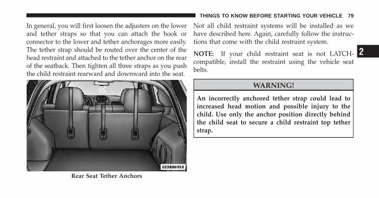
In general, you will first loosen the adjusters on the lowerand tether straps so that you can attach the hook orconnector to the lower and tether anchorages more easily.The tether strap should be routed over the center of thehead restraint and attached to the tether anchor on the rearof the seatback. Then tighten all three straps as you pushthe child restraint rearward and downward into the seat.
Not all child restraint systems will be installed as wehave described here. Again, carefully follow the instruc-tions that come with the child restraint system.
NOTE: If your child restraint seat is not LATCH-compatible, install the restraint using the vehicle seatbelts.
WARNING!
An incorrectly anchored tether strap could lead toincreased head motion and possible injury to thechild. Use only the anchor position directly behindthe child seat to secure a child restraint top tetherstrap.
Rear Seat Tether Anchors
2
THINGS TO KNOW BEFORE STARTING YOUR VEHICLE 79

Transporting PetsAirbags deploying in the front seat could harm your pet.An unrestrained pet will be thrown about and possiblyinjured, or injure a passenger during panic braking or ina collision.
Pets should be restrained in the rear seat in pet harnessesor pet carriers that are secured by seat belts.
ENGINE BREAK-IN RECOMMENDATIONSA long break-in period is not required for the engine anddrivetrain (transmission and axle) in your vehicle.
Drive moderately during the first 300 miles (500 km).After the initial 60 miles (100 km), speeds up to 50 or55 mph (80 or 90 km/h) are desirable.
While cruising, brief full-throttle acceleration within thelimits of local traffic laws, contributes to a good break-in.Wide-open throttle acceleration in low gear can be detri-mental and should be avoided.
The engine oil installed in the engine at the factory is ahigh-quality energy conserving type lubricant. Oilchanges should be consistent with anticipated climateconditions under which vehicle operations will occur. Forthe recommended viscosity and quality grades refer to“Maintenance Procedures” in “Maintaining Your Ve-hicle”. NON-DETERGENT OR STRAIGHT MINERALOILS MUST NEVER BE USED.
A new engine may consume some oil during its first fewthousand miles (kilometers) of operation. This should beconsidered a normal part of the break-in and not inter-preted as an indication of difficulty.
80 THINGS TO KNOW BEFORE STARTING YOUR VEHICLE

SAFETY TIPS
Transporting PassengersNEVER TRANSPORT PASSENGERS IN THE CARGOAREA.
WARNING!
• It is extremely dangerous to ride in a cargo area,inside or outside of a vehicle. In a collision, peopleriding in these areas are more likely to be seri-ously injured or killed.
• Do not allow people to ride in any area of yourvehicle that is not equipped with seats and seatbelts.
• Be sure everyone in your vehicle is in a seat andusing a seat belt properly.
Exhaust Gas
WARNING!
Exhaust gases can injure or kill. They contain carbonmonoxide (CO), which is colorless and odorless.Breathing it can make you unconscious and caneventually poison you. To avoid breathing (CO)follow these safety tips:
Do not run the engine in a closed garage or in confinedareas any longer than needed to move your vehicle in orout of the area.
If it is necessary to sit in a parked vehicle with the enginerunning, adjust your heating or cooling controls to forceoutside air into the vehicle. Set the blower at high speed.
2
THINGS TO KNOW BEFORE STARTING YOUR VEHICLE 81

If you are required to drive with the trunk/liftgate open,make sure that all windows are closed and the climatecontrol BLOWER switch is set at high speed. DO NOTuse the recirculation mode.
The best protection against carbon monoxide entry intothe vehicle body is a properly maintained engine exhaustsystem.
Whenever a change is noticed in the sound of the exhaustsystem, when exhaust fumes can be detected inside thevehicle, or when the underside or rear of the vehicle isdamaged, have a competent mechanic inspect the com-plete exhaust system and adjacent body areas for broken,damaged, deteriorated, or mispositioned parts. Openseams or loose connections could permit exhaust fumesto seep into the passenger compartment. In addition,inspect the exhaust system each time the vehicle is raisedfor lubrication or oil change. Replace as required.
Safety Checks You Should Make Inside theVehicle
Seat BeltsInspect the belt system periodically, checking for cuts,frays, and loose parts. Damaged parts must be replacedimmediately. Do not disassemble or modify the system.
Front seat belt assemblies must be replaced after acollision. Rear seat belt assemblies must be replaced aftera collision if they have been damaged (i.e., bent retractor,torn webbing, etc.). If there is any question regarding beltor retractor condition, replace the belt.
Airbag Warning LightThe light should come on and remain on for six to eightseconds as a bulb check when the ignition switch is firstturned ON. If the light is not lit during starting, see yourauthorized dealer. If the light stays on, flickers, or comeson while driving, have the system checked by an autho-rized dealer.
82 THINGS TO KNOW BEFORE STARTING YOUR VEHICLE
DefrosterCheck operation by selecting the defrost mode and placethe blower control on high speed. You should be able tofeel the air directed against the windshield. See yourauthorized dealer for service if your defroster isinoperable.
Periodic Safety Checks You Should Make Outsidethe Vehicle
TiresExamine tires for excessive tread wear and uneven wearpatterns. Check for stones, nails, glass, or other objectslodged in the tread. Inspect the tread and sidewall forcuts and cracks. Check the wheel nuts for tightness.Check the tires (including spare) for proper pressure.
LightsHave someone observe the operation of exterior lightswhile you work the controls. Check turn signal and highbeam indicator lights on the instrument panel.
Door LatchesCheck for positive closing, latching, and locking.
Fluid LeaksCheck area under vehicle after overnight parking for fuel,engine coolant, oil, or other fluid leaks. Also, if gasolinefumes are detected or if fuel, power steering fluid, orbrake fluid leaks are suspected, the cause should belocated and corrected immediately.
2
THINGS TO KNOW BEFORE STARTING YOUR VEHICLE 83


UNDERSTANDING THE FEATURES OF YOUR VEHICLE
CONTENTS
� Mirrors . . . . . . . . . . . . . . . . . . . . . . . . . . . . . . 89
▫ Inside Day/Night Mirror . . . . . . . . . . . . . . . . 89
▫ Automatic Dimming Mirror — If Equipped . . . 89
▫ Outside Mirror — Driver Side . . . . . . . . . . . . 90
▫ Outside Mirror — Passenger Side . . . . . . . . . . 90
▫ Power Mirrors . . . . . . . . . . . . . . . . . . . . . . . 91
▫ Heated Mirrors — If Equipped . . . . . . . . . . . . 92
▫ Vanity Mirrors — If Equipped . . . . . . . . . . . . 92
▫ Sun Visor Sliding Feature . . . . . . . . . . . . . . . 92
� Uconnect™ phone — If Equipped . . . . . . . . . . . 93
▫ Operation . . . . . . . . . . . . . . . . . . . . . . . . . . 95
▫ Phone Call Features . . . . . . . . . . . . . . . . . . 103
▫ Uconnect™ phone Features . . . . . . . . . . . . . 106
▫ Advanced Phone Connectivity . . . . . . . . . . . 110
▫ Things You Should Know About YourUconnect™ phone . . . . . . . . . . . . . . . . . . . . 112
▫ General Information . . . . . . . . . . . . . . . . . . 121
3

� Voice Command — If Equipped . . . . . . . . . . . 121
▫ Voice Command System Operation . . . . . . . . 121
▫ Commands . . . . . . . . . . . . . . . . . . . . . . . . 123
▫ Voice Training . . . . . . . . . . . . . . . . . . . . . . 126
� Seats . . . . . . . . . . . . . . . . . . . . . . . . . . . . . . 126
▫ Front Seat Adjustment . . . . . . . . . . . . . . . . . 126
▫ Manual Seat Height Adjustment —If Equipped . . . . . . . . . . . . . . . . . . . . . . . . 128
▫ Manual Lumbar — If Equipped . . . . . . . . . . 128
▫ Driver’s Seatback Recline . . . . . . . . . . . . . . . 129
▫ Six-Way Power Seats — If Equipped . . . . . . . 130
▫ Heated Seats — If Equipped . . . . . . . . . . . . 131
▫ Fold-Flat Front Passenger Seat . . . . . . . . . . . 132
▫ Adjusting Active Head Restraints . . . . . . . . . 133
▫ Folding Rear Seat . . . . . . . . . . . . . . . . . . . . 136
� To Open And Close The Hood . . . . . . . . . . . . 138
� Lights . . . . . . . . . . . . . . . . . . . . . . . . . . . . . 140
▫ Multifunction Lever . . . . . . . . . . . . . . . . . . 140
▫ Headlights And Parking Lights . . . . . . . . . . 140
▫ Instrument Panel Dimming . . . . . . . . . . . . . 141
▫ Lights-On Reminder . . . . . . . . . . . . . . . . . . 141
▫ Fog Lights — If Equipped . . . . . . . . . . . . . . 142
▫ Daytime Running Lights — If Equipped . . . . 142
▫ Turn Signals . . . . . . . . . . . . . . . . . . . . . . . . 142
▫ Lane Change Assist . . . . . . . . . . . . . . . . . . . 143
▫ High/Low Beam Switch . . . . . . . . . . . . . . . 143
86 UNDERSTANDING THE FEATURES OF YOUR VEHICLE

▫ Flash-To-Pass . . . . . . . . . . . . . . . . . . . . . . . 143
▫ Map/Reading Lights . . . . . . . . . . . . . . . . . . 144
� Windshield Wipers And Washers . . . . . . . . . . 144
▫ Windshield Wiper Operation . . . . . . . . . . . . 145
▫ Intermittent Wiper System . . . . . . . . . . . . . . 146
▫ Windshield Washers . . . . . . . . . . . . . . . . . . 146
▫ Mist Feature . . . . . . . . . . . . . . . . . . . . . . . . 147
� Tilt Steering Column . . . . . . . . . . . . . . . . . . . 147
� Electronic Speed Control — If Equipped . . . . . 148
▫ To Activate . . . . . . . . . . . . . . . . . . . . . . . . . 149
▫ To Set a Desired Speed . . . . . . . . . . . . . . . . 150
▫ To Deactivate . . . . . . . . . . . . . . . . . . . . . . . 150
▫ To Resume Speed . . . . . . . . . . . . . . . . . . . . 150
▫ To Vary The Speed Setting . . . . . . . . . . . . . . 150
▫ Manual Transaxle . . . . . . . . . . . . . . . . . . . . 151
▫ To Accelerate For Passing . . . . . . . . . . . . . . 151
� Garage Door Opener — If Equipped . . . . . . . . 152
▫ Programming HomeLink� . . . . . . . . . . . . . . 153
▫ Gate Operator/Canadian Programming . . . . 156
▫ Using HomeLink� . . . . . . . . . . . . . . . . . . . 156
▫ Reprogramming A SingleHomeLink� Button . . . . . . . . . . . . . . . . . . . 157
▫ Security . . . . . . . . . . . . . . . . . . . . . . . . . . . 157
▫ Troubleshooting Tips . . . . . . . . . . . . . . . . . . 157
▫ General Information . . . . . . . . . . . . . . . . . . 158
� Power Sunroof — If Equipped . . . . . . . . . . . . 158
3
UNDERSTANDING THE FEATURES OF YOUR VEHICLE 87

▫ Opening The Sunroof . . . . . . . . . . . . . . . . . 159
▫ Closing The Sunroof . . . . . . . . . . . . . . . . . . 159
▫ Pinch Protect Feature . . . . . . . . . . . . . . . . . 160
▫ Pinch Protect Override . . . . . . . . . . . . . . . . 160
▫ Venting Sunroof — Express . . . . . . . . . . . . . 160
▫ Sunshade Operation . . . . . . . . . . . . . . . . . . 160
▫ Wind Buffeting . . . . . . . . . . . . . . . . . . . . . . 161
▫ Sunroof Maintenance . . . . . . . . . . . . . . . . . 161
▫ Ignition Off Operation . . . . . . . . . . . . . . . . . 161
� Electrical Power Outlets . . . . . . . . . . . . . . . . . 161
� Power Inverter — If Equipped . . . . . . . . . . . . 163
� Cupholders . . . . . . . . . . . . . . . . . . . . . . . . . . 165
� Storage . . . . . . . . . . . . . . . . . . . . . . . . . . . . . 166
▫ Glove Compartment And Storage Bin . . . . . . 166
▫ Door Storage . . . . . . . . . . . . . . . . . . . . . . . 167
� Console Features . . . . . . . . . . . . . . . . . . . . . . 168
� Cargo Area Features . . . . . . . . . . . . . . . . . . . 169
▫ Cargo Light/Removable Self-RechargingFlashlight . . . . . . . . . . . . . . . . . . . . . . . . . . 169
▫ Cargo Cover . . . . . . . . . . . . . . . . . . . . . . . . 170
▫ Removable Load Floor . . . . . . . . . . . . . . . . 172
▫ Cargo Tie-Down Loops . . . . . . . . . . . . . . . . 173
▫ Fold Down Speakers — If Equipped . . . . . . . 174
� Rear Window Features . . . . . . . . . . . . . . . . . . 174
▫ Rear Window Wiper/Washer . . . . . . . . . . . . 174
▫ Rear Window Defroster . . . . . . . . . . . . . . . . 175
� Roof Luggage Rack — If Equipped . . . . . . . . . 176
88 UNDERSTANDING THE FEATURES OF YOUR VEHICLE
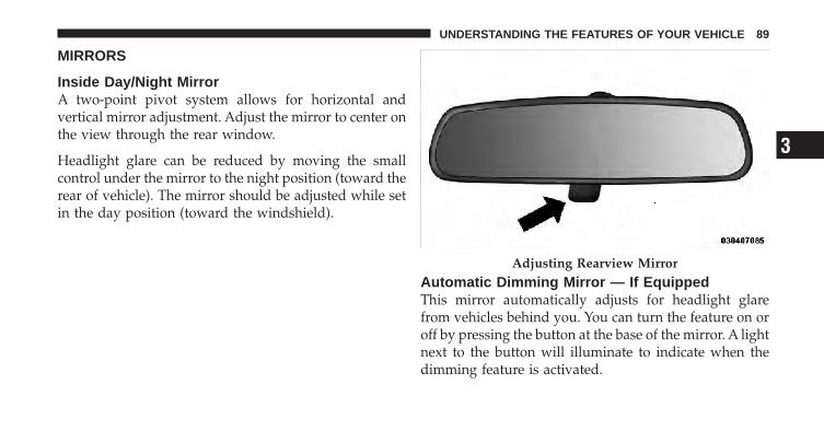
MIRRORS
Inside Day/Night MirrorA two-point pivot system allows for horizontal andvertical mirror adjustment. Adjust the mirror to center onthe view through the rear window.
Headlight glare can be reduced by moving the smallcontrol under the mirror to the night position (toward therear of vehicle). The mirror should be adjusted while setin the day position (toward the windshield).
Automatic Dimming Mirror — If EquippedThis mirror automatically adjusts for headlight glarefrom vehicles behind you. You can turn the feature on oroff by pressing the button at the base of the mirror. A lightnext to the button will illuminate to indicate when thedimming feature is activated.
Adjusting Rearview Mirror
3
UNDERSTANDING THE FEATURES OF YOUR VEHICLE 89
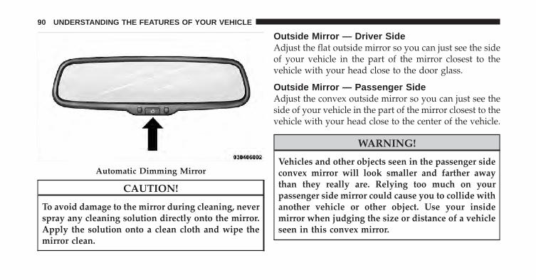
CAUTION!
To avoid damage to the mirror during cleaning, neverspray any cleaning solution directly onto the mirror.Apply the solution onto a clean cloth and wipe themirror clean.
Outside Mirror — Driver SideAdjust the flat outside mirror so you can just see the sideof your vehicle in the part of the mirror closest to thevehicle with your head close to the door glass.
Outside Mirror — Passenger SideAdjust the convex outside mirror so you can just see theside of your vehicle in the part of the mirror closest to thevehicle with your head close to the center of the vehicle.
WARNING!
Vehicles and other objects seen in the passenger sideconvex mirror will look smaller and farther awaythan they really are. Relying too much on yourpassenger side mirror could cause you to collide withanother vehicle or other object. Use your insidemirror when judging the size or distance of a vehicleseen in this convex mirror.
Automatic Dimming Mirror
90 UNDERSTANDING THE FEATURES OF YOUR VEHICLE

Power MirrorsThe control for the power mirrors is located on thedriver’s door trim panel.
To adjust a mirror, turn the control wand toward the leftor right mirror positions indicated. Tilt the control wandin the direction you want the mirror to move. Whenfinished adjusting the mirror, turn the control to thecenter position to prevent accidentally moving a mirror.
Power Mirror Control
Mirror Directions
3
UNDERSTANDING THE FEATURES OF YOUR VEHICLE 91

WARNING!
Vehicles and other objects seen in the passenger sideconvex mirror will look smaller and farther awaythan they really are. Relying too much on yourpassenger side mirror could cause you to collide withanother vehicle or other object. Use your insidemirror when judging the size or distance of a vehicleseen in this convex mirror.
Heated Mirrors — If EquippedThese mirrors are heated to melt frost or ice. Thisfeature is activated whenever you turn on the rear
window defroster. Refer to “Rear Window Features” in“Understanding the Features of Your Vehicle” for furtherinformation.
Vanity Mirrors — If EquippedTo use the vanity mirror, rotate the sun visor down andswing the mirror cover upward.
Sun Visor Sliding FeatureThe sun visors may be extended out to provide morecoverage of the side glass.
Vanity Mirror
92 UNDERSTANDING THE FEATURES OF YOUR VEHICLE
Uconnect™ Phone — IF EQUIPPEDUconnect™ Phone is a voice-activated, hands-free, in-vehicle communications system. Uconnect™ Phone al-lows you to dial a phone number with your cellularphone using simple voice commands (e.g., �Call” �“Mike” �”Work� or �Dial” � “248-555-1212�). Your cellularphone’s audio is transmitted through your vehicle’saudio system; the system will automatically mute yourradio when using the Uconnect™ Phone.
NOTE: The Uconnect™ Phone requires a cellular phoneequipped with the Bluetooth� �Hands-Free Profile,� Ver-sion 0.96 or higher. See the Uconnect™ website forsupported phones.
For Uconnect™ customer support, visit the followingwebsites:
• www.chrysler.com/uconnect
• www.dodge.com/uconnect
• www.jeep.com/uconnect
• or call 1–877–855–8400
Uconnect™ Phone allows you to transfer calls betweenthe system and your cellular phone as you enter or exityour vehicle and enables you to mute the system’smicrophone for private conversation.
The Uconnect™ Phone is driven through your Bluetooth�“Hands-Free Profile” cellular phone. Uconnect™ featuresBluetooth� technology - the global standard that enablesdifferent electronic devices to connect to each other with-out wires or a docking station, so Uconnect™ Phoneworks no matter where you stow your cellular phone (beit your purse, pocket, or briefcase), as long as your phoneis turned on and has been paired to the vehicle’sUconnect™ Phone. The Uconnect™ Phone allows up toseven cellular phones to be linked to the system. Only one
3
UNDERSTANDING THE FEATURES OF YOUR VEHICLE 93

linked (or paired) cellular phone can be used with thesystem at a time. The system is available in English,Spanish, or French languages.
WARNING!
Any voice commanded system should be used onlyin safe driving conditions following local laws andphone use. All attention should be kept on theroadway ahead. Failure to do so may result in anaccident causing serious injury or death.
Uconnect™ Phone ButtonDepending on the vehicle options, eitherthe radio or the mirror will contain the twocontrol buttons (Uconnect™ Phone but-ton) and (Voice Command button) that
will enable you to access the system.
Voice Command ButtonActual button location may vary with the ra-dio. The individual buttons are described in the“Operation” section.
The Uconnect™ Phone can be used with any Hands-FreeProfile certified Bluetooth� cellular phone. See theUconnect™ website for supported phones. If your cellu-lar phone supports a different profile (e.g., HeadsetProfile) you may not be able to use any Uconnect™Phone features. Refer to your cellular service provider orthe phone manufacturer for details.
The Uconnect™ Phone is fully integrated with the vehi-cle’s audio system. The volume of the Uconnect™ Phonecan be adjusted either from the radio volume controlknob or from the steering wheel radio control (rightswitch), if so equipped.
94 UNDERSTANDING THE FEATURES OF YOUR VEHICLE
The radio display will be used for visual prompts fromthe Uconnect™ Phone such as �CELL� or caller ID oncertain radios.
OperationVoice commands can be used to operate the Uconnect™Phone and to navigate through the Uconnect™ Phonemenu structure. Voice commands are required after mostUconnect™ Phone prompts. You will be prompted for aspecific command and then guided through the availableoptions.
• Prior to giving a voice command, one must wait forthe beep, which follows the �Ready� prompt or anotherprompt.
• For certain operations, compound commands can beused. For example, instead of saying �Setup� and then�Phone Pairing,� the following compound commandcan be said: �Setup Phone Pairing.�
• For each feature explanation in this section, only thecombined form of the voice command is given. Youcan also break the commands into parts and say eachpart of the command when you are asked for it. Forexample, you can use the combined form voice com-mand �Phonebook New Entry,� or you can break thecombined form command into two voice commands:�Phonebook� and �New Entry.� Please remember, theUconnect™ Phone works best when you talk in anormal conversational tone, as if speaking to someonesitting a few feet/meters away from you.
Voice Command TreeRefer to “Voice Tree” in this section.
Help CommandIf you need assistance at any prompt, or if you want toknow your options at any prompt, say �Help� followingthe beep. The Uconnect™ Phone will play all the optionsat any prompt if you ask for help.
3
UNDERSTANDING THE FEATURES OF YOUR VEHICLE 95

To activate the Uconnect™ Phone from idle, simply pressthe button and follow the audible prompts fordirections. All Uconnect™ Phone sessions begin with apress of the button on the radio control head.
Cancel CommandAt any prompt, after the beep, you can say �Cancel� andyou will be returned to the main menu. However, in afew instances the system will take you back to theprevious menu.
Pair (Link) Uconnect™ Phone to a Cellular PhoneTo begin using your Uconnect™ Phone, you must pairyour compatible Bluetooth� enabled cellular phone.
To complete the pairing process, you will need to refer-ence your cellular phone Owner’s Manual. TheUconnect™ website may also provide detailed instruc-tions for pairing.
The following are general phone to Uconnect™ Phonepairing instructions:
• Press the button to begin.
• After the �Ready� prompt and the following beep, say�Setup Phone Pairing.�
• When prompted, after the beep, say �Pair a Phone� andfollow the audible prompts.
• You will be asked to say a four-digit Personal Identi-fication Number (PIN), which you will later need toenter into your cellular phone. You can enter anyfour-digit PIN. You will not need to remember this PINafter the initial pairing process.
• For identification purposes, you will be prompted togive the Uconnect™ Phone a name for your cellularphone. Each cellular phone that is paired should begiven a unique phone name.
96 UNDERSTANDING THE FEATURES OF YOUR VEHICLE
• You will then be asked to give your cellular phone apriority level between one and seven, with one beingthe highest priority. You can pair up to seven cellularphones to your Uconnect™ Phone. However, at anygiven time, only one cellular phone can be in use,connected to your Uconnect™ Phone. The priorityallows the Uconnect™ Phone to know which cellularphone to use if multiple cellular phones are in thevehicle at the same time. For example, if priority threeand priority five phones are present in the vehicle, theUconnect™ Phone will use the priority three cellularphone when you make a call. You can select to use alower priority cellular phone at any time (refer to�Advanced Phone Connectivity� in this section).
Dial by Saying a Number
• Press the button to begin.
• After the �Ready� prompt and the following beep, say�Dial.�
• The system will prompt you to say the number youwant to call.
• For example, you can say �234-567-8901�.
• The Uconnect™ Phone will confirm the phone numberand then dial. The number will appear in the displayof certain radios.
Call by Saying a Name
• Press the button to begin.
• After the �Ready� prompt and the following beep, say“Call.�
• The system will prompt you to say the name of theperson you want to call.
• After the �Ready� prompt and the following beep, saythe name of the person you want to call. For example,you can say �John Doe,� where John Doe is a previ-ously stored name entry in the Uconnect™ phonebook
3
UNDERSTANDING THE FEATURES OF YOUR VEHICLE 97

or downloaded phonebook. To learn how to store aname in the phonebook, refer to �Add Names to YourUconnect™ Phonebook,� in the phonebook.
• The Uconnect™ system will confirm the name andthen dial the corresponding phone number, whichmay appear in the display of certain radios.
Add Names to Your Uconnect™ Phonebook
NOTE: Adding names to the Uconnect™ Phonebook isrecommended when the vehicle is not in motion.
• Press the button to begin.
• After the �Ready� prompt and the following beep, say�Phonebook New Entry.�
• When prompted, say the name of the new entry. Use oflong names helps the Voice Command and it is recom-mended. For example, say �Robert Smith� or �Robert�instead of �Bob.�
• When prompted, enter the number designation (e.g.,�Home,� �Work,� �Mobile,� or �Pager�). This will allowyou to store multiple numbers for each phonebookentry, if desired.
• When prompted, recite the phone number for thephonebook entry that you are adding.
After you are finished adding an entry into the phone-book, you will be given the opportunity to add morephone numbers to the current entry or to return to themain menu.
The Uconnect™ Phone will allow you to enter up to 32names in the phonebook with each name having up tofour associated phone numbers and designations. Eachlanguage has a separate 32-name phonebook accessibleonly in that language. In addition, if equipped andsupported by your phone, Uconnect™ Phone automati-cally downloads your cellular phone’s phonebook.
98 UNDERSTANDING THE FEATURES OF YOUR VEHICLE

Phonebook Download – Automatic PhonebookTransfer From Cellular PhoneIf equipped and specifically supported by your phone,Uconnect™ Phone automatically downloads names (textnames) and number entries from the cellular phone’sphonebook. Specific Bluetooth� Phones with Phone BookAccess Profile may support this feature. See Uconnect™website for supported phones.
• To call a name from downloaded (or Uconnect™)Phonebook, follow the procedure in “Call by Saying aName” section.
• Automatic download and update, if supported, beginsas soon as the Bluetooth� wireless phone connection ismade to the Uconnect™ Phone, for example, after youstart the vehicle.
• A maximum of 1000 entries per phone will be down-loaded and updated every time a phone is connectedto the Uconnect™ Phone.
• Depending on the maximum number of entries down-loaded, there may be a short delay before the latestdownloaded names can be used. Until then, if avail-able, the previous downloaded phonebook is availablefor use.
• Only the phonebook of the currently connected cellu-lar phone is accessible.
• Only the cellular phone’s phonebook is downloaded.SIM card phonebook is not part of the Mobile phone-book.
• This downloaded phonebook cannot be edited ordeleted on the Uconnect™ Phone. These can only beedited on the cellular phone. The changes are trans-ferred and updated to Uconnect™ Phone on the nextphone connection.
3
UNDERSTANDING THE FEATURES OF YOUR VEHICLE 99

Phonebook Download — Single EntryIf equipped and supported by your phone, Uconnect™Phone allows the user to download entries from theirphone via Bluetooth�. To use this feature, press thebutton and say “Phonebook Download.” The systemprompts, “Ready to accept “V” card entry viaBluetooth�…” The system is now ready to accept phone-book entries from your phone using the Bluetooth�Object Exchange Profile (OBEX). Please see your phoneOwner’s Manual for specific instructions on how to sendthese entries from your phone.
NOTE:• The phone handset must support Bluetooth� OBEX
transfers of phonebook entries to use this feature.
• Some phones cannot send phonebook entries if theyare already connected to any system via Bluetooth�,and you may see a message on the phone display thatthe Bluetooth� link is busy. In this case, the user must
first disconnect or drop the Bluetooth� connection tothe Uconnect™ Phone, and then send the addressbook entry via Bluetooth�. Please see your phoneOwner’s Manual for specific instructions on how todrop the Bluetooth� connection.
• If the phonebook entry is longer than 24 characters, itwill only use the first 24 characters.
Edit Uconnect™ Phonebook Entries
NOTE:• Editing names in the phonebook is recommended
when the vehicle is not in motion.
• Automatic downloaded phonebook entries cannot bedeleted or edited.
• Press the button to begin.
• After the �Ready� prompt and the following beep, say�Phonebook Edit.�
100 UNDERSTANDING THE FEATURES OF YOUR VEHICLE

• You will then be asked for the name of the phonebookentry that you wish to edit.
• Next, choose the number designation (home, work,cellular, or pager) that you wish to edit.
• When prompted, recite the new phone number for thephonebook entry that you are editing.
After you are finished editing an entry in the phonebook,you will be given the opportunity to edit another entry inthe phonebook, call the number you just edited, or returnto the main menu.
�Phonebook Edit� can be used to add another phonenumber to a name entry that already exists in thephonebook. For example, the entry John Doe may have acellular and a home number, but you can add ”JohnDoe’s” work number later using the �Phonebook Edit�feature.
Delete Uconnect™ Phonebook Entry
NOTE: Editing phonebook entries is recommendedwhen the vehicle is not in motion.
• Press the button to begin.
• After the �Ready� prompt and the following beep, say�Phonebook Delete.�
• After you enter the Phonebook Delete menu, you willthen be asked for the name of the entry that you wishto delete. You can either say the name of a phonebookentry that you wish to delete or you can say �ListNames� to hear a list of the entries in the phonebookfrom which you choose. To select one of the entriesfrom the list, press the button while theUconnect™ Phone is playing the desired entry and say�Delete.�
3
UNDERSTANDING THE FEATURES OF YOUR VEHICLE 101
• After you enter the name, the Uconnect™ Phone willask you which designation you wish to delete: home,work, cellular, pager, or all. Say the designation youwish to delete.
• Note that only the phonebook entry in the currentlanguage is deleted.
• Automatic downloaded phonebook entries cannot bedeleted or edited.
Delete/Erase “All” Uconnect™ Phonebook Entries
• Press the button to begin.
• After the �Ready� prompt and the following beep, say�Phonebook Erase All.�
• The Uconnect™ Phone will ask you to verify that youwish to delete all the entries from the phonebook.
• After confirmation, the phonebook entries will bedeleted.
• Note that only the phonebook in the current languageis deleted.
• Automatic downloaded phonebook entries cannot bedeleted or edited.
List All Names in the Uconnect™ Phonebook
• Press the button to begin.
• After the �Ready� prompt and the following beep, say�Phonebook List Names.�
• The Uconnect™ Phone will play the names of all thephonebook entries, including the downloaded phone-book entries, if available.
• To call one of the names in the list, press thebutton during the playing of the desired name, andsay �Call.�
NOTE: The user can also exercise �Edit� or �Delete�operations at this point.
102 UNDERSTANDING THE FEATURES OF YOUR VEHICLE

• The Uconnect™ Phone will then prompt you as to thenumber designation you wish to call.
• The selected number will be dialed.
Phone Call FeaturesThe following features can be accessed through theUconnect™ Phone if the feature(s) are available on yourcellular service plan. For example, if your cellular serviceplan provides three-way calling, this feature can beaccessed through the Uconnect™ Phone. Check withyour cellular service provider for the features that youhave.
Answer or Reject an Incoming Call - No CallCurrently in ProgressWhen you receive a call on your cellular phone, theUconnect™ Phone will interrupt the vehicle audio sys-tem, if on, and will ask if you would like to answer thecall. Press the button to accept the call. To reject the
call, press and hold the button until you hear asingle beep, indicating that the incoming call wasrejected.
Answer or Reject an Incoming Call - CallCurrently in ProgressIf a call is currently in progress and you have anotherincoming call, you will hear the same network tones forcall waiting that you normally hear when using yourcellular phone. Press the button to place the currentcall on hold and answer the incoming call.
NOTE: The Uconnect™ Phone compatible phones in themarket today do not support rejecting an incoming callwhen another call is in progress. Therefore, the user canonly answer an incoming call or ignore it.
Making a Second Call While Current Call is inProgressTo make a second call while you are currently on a call,press the button and say �Dial� or �Call� followed
3
UNDERSTANDING THE FEATURES OF YOUR VEHICLE 103
by the phone number or phonebook entry you wish tocall. The first call will be on hold while the second call isin progress. To go back to the first call, refer to �TogglingBetween Calls� in this section. To combine two calls, referto �Conference Call� in this section.
Place/Retrieve a Call From HoldTo put a call on hold, press the button until you heara single beep. This indicates that the call is on hold. Tobring the call back from hold, press and hold thebutton until you hear a single beep.
Toggling Between CallsIf two calls are in progress (one active and one on hold),press the button until you hear a single beep,indicating that the active and hold status of the two callshave switched. Only one call can be placed on hold at atime.
Conference CallWhen two calls are in progress (one active and one onhold), press and hold the button until you hear adouble beep indicating that the two calls have beenjoined into one conference call.
Three-Way CallingTo initiate three-way calling, press the buttonwhile a call is in progress, and make a second phone call,as described under �Making a Second Call While CurrentCall is in Progress.� After the second call has established,press and hold the button until you hear a doublebeep, indicating that the two calls have been joined intoone conference call.
104 UNDERSTANDING THE FEATURES OF YOUR VEHICLE

Call TerminationTo end a call in progress, momentarily press thebutton. Only the active call(s) will be terminated and ifthere is a call on hold, it will become the new active call.If the active call is terminated by the phone far end, a callon hold may not become active automatically. This is cellphone-dependent. To bring the call back from hold, pressand hold the button until you hear a single beep.
Redial
• Press the button to begin.
• After the �Ready� prompt and the following beep, say�Redial.�
• The Uconnect™ Phone will call the last number thatwas dialed from your cellular phone.
NOTE: This may not be the last number dialed from theUconnect™ Phone.
Call ContinuationCall continuation is the progression of a phone call on theUconnect™ Phone after the vehicle ignition key has beenswitched to OFF. Call continuation functionality avail-able on the vehicle can be any one of three types:
• After the ignition key is switched to OFF, a call cancontinue on the Uconnect™ Phone either until the callends, or until the vehicle battery condition dictatescessation of the call on the Uconnect™ Phone andtransfer of the call to the cellular phone.
• After the ignition key is switched to OFF, a call cancontinue on the Uconnect™ Phone for a certain dura-tion, after which the call is automatically transferredfrom the Uconnect™ Phone to the cellular phone.
• An active call is automatically transferred to thecellular phone after the ignition key is switched toOFF.
3
UNDERSTANDING THE FEATURES OF YOUR VEHICLE 105

Uconnect™ Phone Features
Language SelectionTo change the language that the Uconnect™ Phone isusing:
• Press the button to begin.
• After the �Ready� prompt and the following beep, saythe name of the language you wish to switch toEnglish, Espanol, or Francais.
• Continue to follow the system prompts to completethe language selection.
After selecting one of the languages, all prompts andvoice commands will be in that language.
NOTE: After every Uconnect™ Phone language changeoperation, only the language-specific 32-name phone-book is usable. The paired phone name is not language-specific and usable across all languages.
Emergency AssistanceIf you are in an emergency and the cellular phone isreachable:
• Pick up the phone and manually dial the emergencynumber for your area.
If the phone is not reachable and the Uconnect™ Phone isoperational, you may reach the emergency number asfollows:
• Press the button to begin.
• After the �Ready� prompt and the following beep, say�Emergency� and the Uconnect™ Phone will instructthe paired cellular phone to call the emergency num-ber. This feature is supported in the U.S., Canada, andMexico.
NOTE:• The emergency number dialed is based on the country
where the vehicle is purchased (911 for the U.S. and
106 UNDERSTANDING THE FEATURES OF YOUR VEHICLE
Canada and 060 for Mexico). The number dialed maynot be applicable with the available cellular serviceand area.
• If supported, this number may be programmable onsome systems. To do this, press the button andsay ‘Setup’, followed by ‘Emergency’.
• The Uconnect™ Phone does slightly lower yourchances of successfully making a phone call as to thatfor the cellular phone directly.
WARNING!
Your phone must be turned on and paired to theUconnect™ Phone to allow use of this vehicle featurein emergency situations, when the cellular phone hasnetwork coverage and stays paired to the Uconnect™Phone.
Towing AssistanceIf you need towing assistance:
• Press the button to begin.
• After the �Ready� prompt and the following beep, say�Towing Assistance.�
NOTE:• The towing assistance number dialed is based on the
country where the vehicle is purchased (1-800-528-2069 for the U.S., 1-877-213-4525 for Canada, 55-14-3454 for Mexico City and 1-800-712-3040 for outsideMexico City in Mexico). Please refer to the 24-Hour�Towing Assistance� coverage details on the DVD inthe Warranty Information Booklet and the 24-HourTowing Assistance references.
• If supported, this number may be programmable onsome systems. To do this, press the button andsay “Setup”, followed by “Towing Assistance”.
3
UNDERSTANDING THE FEATURES OF YOUR VEHICLE 107

PagingTo learn how to page, refer to �Working with AutomatedSystems.� Paging works properly except for pagers ofcertain companies, which time out a little too soon towork properly with the Uconnect™ Phone.
Voice Mail CallingTo learn how to access your voice mail, refer to �Workingwith Automated Systems.�
Working with Automated SystemsThis method is used in instances where one generally hasto press numbers on the cellular phone keypad whilenavigating through an automated telephone system.
You can use your Uconnect™ Phone to access a voicemail system or an automated service, such as a pagingservice or automated customer service line. Some ser-vices require immediate response selection. In someinstances, that may be too quick for use of theUconnect™ Phone.
When calling a number with your Uconnect™ Phone thatnormally requires you to enter in a touch-tone sequenceon your cellular phone keypad, you can press thebutton and say the sequence you wish to enter, followedby the word �Send.� For example, if required to enteryour PIN followed with a pound, (3 7 4 6 #), you canpress the button and say, �3 7 4 6 # Send.� Sayinga number, or sequence of numbers, followed by �Send,� isalso to be used for navigating through an automatedcustomer service center menu structure, and to leave anumber on a pager.
You can also send stored Uconnect™ phonebook entriesas tones for fast and easy access to voice mail and pagerentries. To use this feature, dial the number you wish tocall and then press the button and say, “Send.” Thesystem will prompt you to enter the name or number andsay the name of the phonebook entry you wish to send.
108 UNDERSTANDING THE FEATURES OF YOUR VEHICLE
The Uconnect™ Phone will then send the correspondingphone number associated with the phonebook entry, astones over the phone.
NOTE:• You may not hear all of the tones due to cellular phone
network configurations. This is normal.
• Some paging and voice mail systems have system timeout settings that are too short and may not allow theuse of this feature.
Barge In - Overriding PromptsThe “Voice Command” button can be used when youwish to skip part of a prompt and issue your voicecommand immediately. For example, if a prompt isasking �Would you like to pair a phone, clear a...,� youcould press the button and say, �Pair a Phone� toselect that option without having to listen to the rest ofthe voice prompt.
Turning Confirmation Prompts ON/OFFTurning confirmation prompts off will stop the systemfrom confirming your choices (e.g., the Uconnect™Phone will not repeat a phone number before you dial it).
• Press the button to begin.
• After the �Ready� prompt and the following beep, say�Setup Confirmations.� The Uconnect™ Phone willplay the current confirmation prompt status and youwill be given the choice to change it.
Phone and Network Status IndicatorsIf available on the radio and/or on a premium displaysuch as the instrument panel cluster, and supported byyour cellular phone, the Uconnect™ Phone will providenotification to inform you of your phone and networkstatus when you are attempting to make a phone callusing Uconnect™ Phone. The status is given for roaming,network signal strength, phone battery strength, etc.
3
UNDERSTANDING THE FEATURES OF YOUR VEHICLE 109
Dialing Using the Cellular Phone KeypadYou can dial a phone number with your cellular phonekeypad and still use the Uconnect™ Phone (while dialingvia the cellular phone keypad, the user must exercisecaution and take precautionary safety measures). Bydialing a number with your paired Bluetooth� cellularphone, the audio will be played through your vehicle’saudio system. The Uconnect™ Phone will work the sameas if you dial the number using Voice Command.
NOTE: Certain brands of cellular phones do not sendthe dial ring to the Uconnect™ Phone to play it on thevehicle audio system, so you will not hear it. Under thissituation, after successfully dialing a number the usermay feel that the call did not go through even though thecall is in progress. Once your call is answered, you willhear the audio.
Mute/Un-Mute (Mute OFF)When you mute the Uconnect™ Phone, you will still beable to hear the conversation coming from the otherparty, but the other party will not be able to hear you. Inorder to mute the Uconnect™ Phone:
• Press the button.
• Following the beep, say �Mute.�
In order to un-mute the Uconnect™ Phone:
• Press the button.
• Following the beep, say �Mute off.�
Advanced Phone Connectivity
Transfer Call to and from Cellular PhoneThe Uconnect™ Phone allows ongoing calls to be trans-ferred from your cellular phone to the Uconnect™ Phonewithout terminating the call. To transfer an ongoing call
110 UNDERSTANDING THE FEATURES OF YOUR VEHICLE
from your Uconnect™ Phone paired cellular phone to theUconnect™ Phone or vice versa, press the buttonand say �Transfer Call.�
Connect or Disconnect Link Between theUconnect™ Phone and Cellular PhoneYour cellular phone can be paired with many differentelectronic devices, but can only be actively �connected�with one electronic device at a time.
If you would like to connect or disconnect the Bluetooth�connection between a Uconnect™ Phone paired cellularphone and the Uconnect™ Phone, follow the instructionsdescribed in your cellular phone User’s Manual.
List Paired Cellular Phone Names
• Press the button to begin.
• After the “Ready” prompt and the following beep, say“Setup Phone Pairing.”
• When prompted, say �List Phones.�
• The Uconnect™ Phone will play the phone names ofall paired cellular phones in order from the highest tothe lowest priority. To “select” or “delete” a pairedphone being announced, press the button andsay “Select” or “Delete.” Also, see the next two sec-tions for an alternate way to “select” or “delete” apaired phone.
Select Another Cellular PhoneThis feature allows you to select and start using anotherphone paired with the Uconnect™ Phone.
• Press the button to begin.
• After the �Ready� prompt and the following beep, say�Setup Select Phone� and follow the prompts.
• You can also press the button at any time whilethe list is being played, and then choose the phone thatyou wish to select.
3
UNDERSTANDING THE FEATURES OF YOUR VEHICLE 111
• The selected phone will be used for the next phonecall. If the selected phone is not available, theUconnect™ Phone will return to using the highestpriority phone present in or near (approximatelywithin 30 ft (9 m)) the vehicle.
Delete Uconnect™ Phone Paired Cellular Phones
• Press the button to begin.
• After the �Ready� prompt and the following beep, say�Setup Phone Pairing.�
• At the next prompt, say �Delete� and follow theprompts.
• You can also press the button at any time whilethe list is being played, and then choose the phone youwish to delete.
Things You Should Know About Your Uconnect™Phone
Uconnect™ Phone TutorialTo hear a brief tutorial of the system features, pressthe button and say “Uconnect™ Tutorial.”
Voice TrainingFor users experiencing difficulty with the system recog-nizing their voice commands or numbers, the Uconnect™Phone Voice Training feature may be used. To enter thistraining mode, follow one of the two following proce-dures:
From outside the Uconnect™ Phone mode (e.g., fromradio mode):
• Press and hold the button for five seconds untilthe session begins, or,
• Press the button and say the �Setup, VoiceTraining� command.
112 UNDERSTANDING THE FEATURES OF YOUR VEHICLE

Repeat the words and phrases when prompted by theUconnect™ Phone. For best results, the Voice Trainingsession should be completed when the vehicle is parkedwith the engine running, all windows closed, and theblower fan switched off.
This procedure may be repeated with a new user. Thesystem will adapt to the last trained voice only.
To restore the Voice Command system to factory defaultsettings, enter the Voice Training session via the aboveprocedure and follow the prompts.
Voice Command
• For best performance, adjust the rearview mirror toprovide at least 1⁄2 in (1 cm) gap between the overheadconsole (if equipped) and the mirror.
• Always wait for the beep before speaking.
• Speak normally, without pausing, just as you wouldspeak to a person sitting a few feet/meters away fromyou.
• Make sure that no one other than you is speakingduring a Voice Command period.
• Performance is maximized under:
• low-to-medium blower setting,
• low-to-medium vehicle speed,
• low road noise,
• smooth road surface,
• fully closed windows,
• dry weather condition.
• Even though the system is designed for users speakingin North American English, French, and Spanish ac-cents, the system may not always work for some.
3
UNDERSTANDING THE FEATURES OF YOUR VEHICLE 113

• When navigating through an automated system suchas voice mail, or when sending a page, at the end ofspeaking the digit string, make sure to say �Send.�
• Storing names in the phonebook when the vehicle isnot in motion is recommended.
• It is not recommended to store similar soundingnames in the Uconnect™ Phonebook.
• Phonebook (Downloaded and Uconnect™ Phone Lo-cal) name recognition rate is optimized when theentries are not similar.
• Numbers must be spoken in single digits. “800” mustbe spoken “eight-zero-zero” not “eight hundred”.
• You can say �O� (letter �O�) for �0� (zero).
• Even though international dialing for most numbercombinations is supported, some shortcut dialingnumber combinations may not be supported.
• In a convertible vehicle, system performance may becompromised with the convertible top down.
Phone Far End Audio Performance
• Audio quality is maximized under:
• low-to-medium blower setting,
• low-to-medium vehicle speed,
• low road noise,
• smooth road surface,
• fully closed windows,
• dry weather conditions, and
• operation from the driver’s seat.
114 UNDERSTANDING THE FEATURES OF YOUR VEHICLE

• Performance, such as audio clarity, echo, and loudnessto a large degree rely on the phone and network, andnot the Uconnect™ Phone.
• Echo at the phone far end can sometimes be reducedby lowering the in-vehicle audio volume.
• In a convertible vehicle, system performance may becompromised with the convertible top down.
Bluetooth� Communication LinkCellular phones have been found to lose connection tothe Uconnect™ Phone. When this happens, the connec-tion can generally be reestablished by switching thephone off/on. Your cellular phone is recommended toremain in Bluetooth� ON mode.
Power-UpAfter switching the ignition key from OFF to either theON or ACC position, or after a language change, youmust wait at least five seconds prior to using the system.
3
UNDERSTANDING THE FEATURES OF YOUR VEHICLE 115

116 UNDERSTANDING THE FEATURES OF YOUR VEHICLE
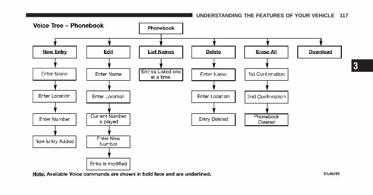
3
UNDERSTANDING THE FEATURES OF YOUR VEHICLE 117

118 UNDERSTANDING THE FEATURES OF YOUR VEHICLE

Voice CommandsPrimary Alternate(s)zeroonetwothreefourfivesixseveneightninestar (*)plus (+)pound (#)add locationall
Voice CommandsPrimary Alternate(s)callcancelconfirmation promptscontinuedeletedialdownloadeditemergencyEnglisherase allEspanolFrancaishelphome
3
UNDERSTANDING THE FEATURES OF YOUR VEHICLE 119
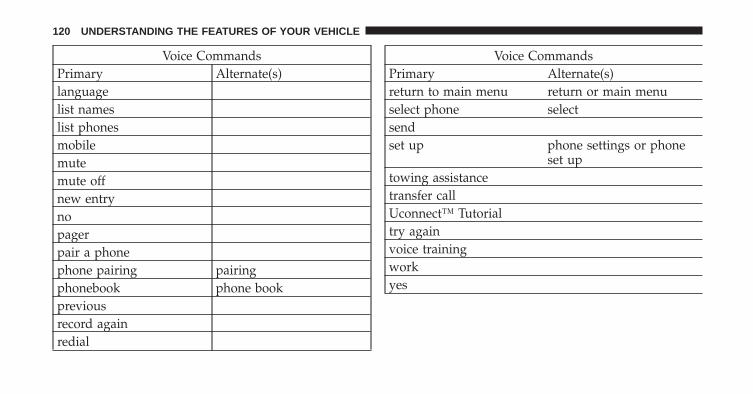
Voice CommandsPrimary Alternate(s)languagelist nameslist phonesmobilemutemute offnew entrynopagerpair a phonephone pairing pairingphonebook phone bookpreviousrecord againredial
Voice CommandsPrimary Alternate(s)return to main menu return or main menuselect phone selectsendset up phone settings or phone
set uptowing assistancetransfer callUconnect™ Tutorialtry againvoice trainingworkyes
120 UNDERSTANDING THE FEATURES OF YOUR VEHICLE

General InformationThis device complies with Part 15 of the FCC rules andRSS 210 of Industry Canada. Operation is subject to thefollowing conditions:
• Changes or modifications not expressly approved bythe party responsible for compliance could void theuser’s authority to operate the equipment.
• This device may not cause harmful interference.
• This device must accept any interference received,including interference that may cause undesiredoperation.
VOICE COMMAND — IF EQUIPPED
Voice Command System OperationThis Voice Command system allows you tocontrol your AM, FM radio, satellite radio, discplayer, and a memo recorder.
NOTE: Take care to speak into the Voice InterfaceSystem as calmly and normally as possible. The ability ofthe Voice Interface System to recognize user voice com-mands may be negatively affected by rapid speaking or araised voice level.
WARNING!
Any voice commanded system should be used onlyin safe driving conditions following local laws andphone use. All attention should be kept on theroadway ahead. Failure to do so may result in anaccident causing serious injury or death.
When you press the Voice Command button, youwill hear a beep. The beep is your signal to give acommand.
3
UNDERSTANDING THE FEATURES OF YOUR VEHICLE 121

NOTE: If you do not say a command within a fewseconds, the system will present you with a list ofoptions.
If you ever wish to interrupt the system while it listsoptions, press the Voice Command button, listenfor the beep, and say your command.
Pressing the Voice Command button while thesystem is speaking is known as “barging in.” The systemwill be interrupted, and after the beep, you can add orchange commands. This will become helpful once youstart to learn the options.
NOTE: At any time, you can say the words “Cancel”,“Help” or “Main Menu”.
These commands are universal and can be used from anymenu. All other commands can be used depending uponthe active application.
For example, if you are in the disc menu and you arelistening to FM radio, you can speak commands from thedisc menu or from the FM radio menu.
When using this system, you should speak clearly and ata normal speaking volume.
The system will best recognize your speech if the win-dows are closed, and the heater/air conditioning fan isset to low.
At any point, if the system does not recognize one of yourcommands, you will be prompted to repeat it.
To hear the first available Menu, press the VoiceCommand button and say “Help” or “MainMenu”.
122 UNDERSTANDING THE FEATURES OF YOUR VEHICLE

CommandsThe Voice Command system understands two types ofcommands. Universal commands are available at alltimes. Local commands are available if the supportedradio mode is active.
Changing the Volume
1. Start a dialogue by pressing the Voice Commandbutton.
2. Say a command (e.g., “Help”).
3. Use the ON/OFF VOLUME rotary knob to adjust thevolume to a comfortable level while the Voice Commandsystem is speaking. Please note the volume setting forVoice Command is different than the audio system.
Main MenuStart a dialogue by pressing the Voice Commandbutton. You may say “Main Menu” to switch to the mainmenu.
In this mode, you can say the following commands:
• “Radio” (to switch to the radio mode)
• “Disc” (to switch to the disc mode)
• “Memo” (to switch to the memo recorder)
• “System Setup” (to switch to system setup)
Radio AM (or Radio Long Wave or Radio MediumWave — If Equipped)To switch to the AM band, say “AM” or “Radio AM”. Inthis mode, you may say the following commands:
• “Frequency” (to change the frequency)
• “Next Station” (to select the next station)
• “Previous Station” (to select the previous station)
• “Radio Menu” (to switch to the radio menu)
• “Main Menu” (to switch to the main menu)
3
UNDERSTANDING THE FEATURES OF YOUR VEHICLE 123

Radio FMTo switch to the FM band, say “FM” or “Radio FM”. Inthis mode, you may say the following commands:
• “Frequency” (to change the frequency)
• “Next Station” (to select the next station)
• “Previous Station” (to select the previous station)
• “Radio Menu” (to switch to the radio menu)
• “Main Menu” (to switch to the main menu)
Satellite RadioTo switch to satellite radio mode, say “Sat” or “SatelliteRadio”. In this mode, you may say the following com-mands:
• “Channel Number” (to change the channel by itsspoken number)
• “Next Channel” (to select the next channel)
• “Previous Channel” (to select the previous channel)
• “List Channel” (to hear a list of available channels)
• “Select Name” (to say the name of a channel)
• “Radio Menu” (to switch to the radio menu)
• “Main Menu” (to switch to the main menu)
DiscTo switch to the disc mode, say “Disc”. In this mode, youmay say the following commands:
• “Track” (#) (to change the track)
• “Next Track” (to play the next track)
• “Previous Track” (to play the previous track)
• “Main Menu” (to switch to the main menu)
124 UNDERSTANDING THE FEATURES OF YOUR VEHICLE

MemoTo switch to the voice recorder mode, say “Memo”. Inthis mode, you may say the following commands:
• “New Memo” (to record a new memo) — During therecording, you may press the Voice Commandbutton to stop recording. You proceed by saying one ofthe following commands:
− “Save” (to save the memo)
− “Continue” (to continue recording)
− “Delete” (to delete the recording)
• “Play Memos” (to play previously recorded memos)— During the playback you may press the VoiceCommand button to stop playing memos. Youproceed by saying one of the following commands:
− “Repeat” (to repeat a memo)
− “Next” (to play the next memo)
− “Previous” (to play the previous memo)
− “Delete” (to delete a memo)
• “Delete All” (to delete all memos)
System SetupTo switch to system setup, say “Setup”. In this mode, youmay say the following commands:
• “Language German”
• “Language Dutch”
• “Language Italian”
• “Language English”
• “Language French”
• “Language Spanish”
• “Tutorial”
• “Voice Training”
3
UNDERSTANDING THE FEATURES OF YOUR VEHICLE 125
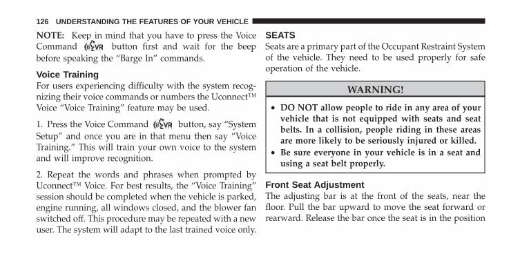
NOTE: Keep in mind that you have to press the VoiceCommand button first and wait for the beepbefore speaking the “Barge In” commands.
Voice TrainingFor users experiencing difficulty with the system recog-nizing their voice commands or numbers the Uconnect™Voice “Voice Training” feature may be used.
1. Press the Voice Command button, say “SystemSetup” and once you are in that menu then say “VoiceTraining.” This will train your own voice to the systemand will improve recognition.
2. Repeat the words and phrases when prompted byUconnect™ Voice. For best results, the “Voice Training”session should be completed when the vehicle is parked,engine running, all windows closed, and the blower fanswitched off. This procedure may be repeated with a newuser. The system will adapt to the last trained voice only.
SEATSSeats are a primary part of the Occupant Restraint Systemof the vehicle. They need to be used properly for safeoperation of the vehicle.
WARNING!
• DO NOT allow people to ride in any area of yourvehicle that is not equipped with seats and seatbelts. In a collision, people riding in these areasare more likely to be seriously injured or killed.
• Be sure everyone in your vehicle is in a seat andusing a seat belt properly.
Front Seat AdjustmentThe adjusting bar is at the front of the seats, near thefloor. Pull the bar upward to move the seat forward orrearward. Release the bar once the seat is in the position
126 UNDERSTANDING THE FEATURES OF YOUR VEHICLE

desired. Then, using body pressure, move forward andrearward on the seat to be sure that the seat adjustershave latched.
WARNING!
Adjusting a seat while the vehicle is moving isdangerous. The sudden movement of the seat couldcause you to lose control. The seat belt might not beproperly adjusted and you could be injured. Adjustthe seat only while the vehicle is parked.
Front Seat Adjustment
3
UNDERSTANDING THE FEATURES OF YOUR VEHICLE 127
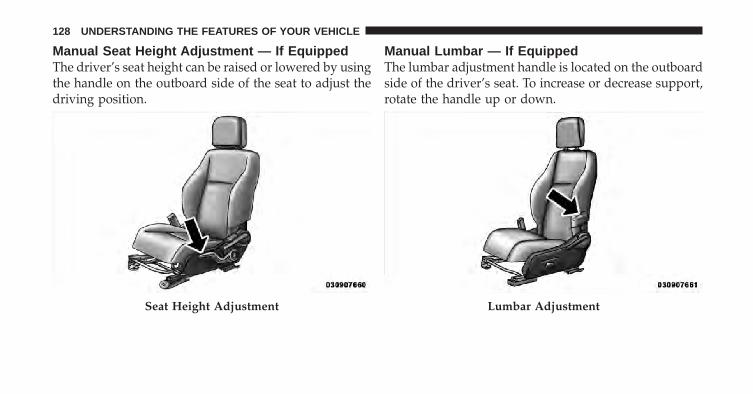
Manual Seat Height Adjustment — If EquippedThe driver’s seat height can be raised or lowered by usingthe handle on the outboard side of the seat to adjust thedriving position.
Manual Lumbar — If EquippedThe lumbar adjustment handle is located on the outboardside of the driver’s seat. To increase or decrease support,rotate the handle up or down.
Seat Height Adjustment Lumbar Adjustment
128 UNDERSTANDING THE FEATURES OF YOUR VEHICLE

Driver’s Seatback ReclineTo recline the seatback, lean forward before lifting thehandle, then lean back to the desired position and releasethe handle. Lift the handle to return the seatback to anupright position.
WARNING!
Do not ride with the seatback reclined so that theshoulder belt is no longer resting against your chest.In a collision you could slide under the seat belt andbe seriously or even fatally injured. Use the reclineronly when the vehicle is parked.
Reclining Seat
3
UNDERSTANDING THE FEATURES OF YOUR VEHICLE 129
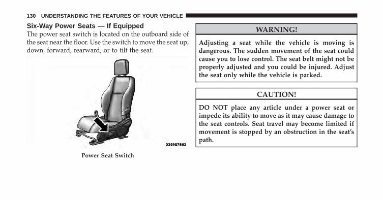
Six-Way Power Seats — If EquippedThe power seat switch is located on the outboard side ofthe seat near the floor. Use the switch to move the seat up,down, forward, rearward, or to tilt the seat.
WARNING!
Adjusting a seat while the vehicle is moving isdangerous. The sudden movement of the seat couldcause you to lose control. The seat belt might not beproperly adjusted and you could be injured. Adjustthe seat only while the vehicle is parked.
CAUTION!
DO NOT place any article under a power seat orimpede its ability to move as it may cause damage tothe seat controls. Seat travel may become limited ifmovement is stopped by an obstruction in the seat’spath.
Power Seat Switch
130 UNDERSTANDING THE FEATURES OF YOUR VEHICLE

Heated Seats — If EquippedThis feature heats the front driver and passenger seats.The heaters provide the same heat level for both the seatcushion and the seatback. The controls for the frontheated seats are located on the center instrument panelarea.
After turning the ignition ON, you can choose from High,Low, or Off heat settings. Amber indicator lights in eachswitch indicate the level of heat in use. Two indicatorlights will illuminate for High, one for Low, and none forOff.
Press the switch once to select High-level heat-ing. Press the switch a second time to selectLow-level heating. Press the switch a third timeto shut the heating elements Off.
If High-level heating is selected, the system automaticallyswitches to Low-level heating and turns one indicatorlight Off after 30 minutes of continuous operation. It will
turn the heater and the remaining indicator light off afteran additional 30 minutes of continuous operation. IfLow-level heating is selected, the system automaticallyturns the heater and the indicator light Off after 30 min-utes of continuous operation.
NOTE: Once a heat setting is selected, heat will be feltwithin two to five minutes.
WARNING!
• Persons who are unable to feel pain to the skinbecause of advanced age, chronic illness, diabetes,spinal cord injury, medication, alcohol use, ex-haustion or other physical condition must exercisecare when using the seat heater. It may cause burnseven at low temperatures, especially if used forlong periods of time.
(Continued)
3
UNDERSTANDING THE FEATURES OF YOUR VEHICLE 131

WARNING! (Continued)• Do not place anything on the seat that insulates
against heat, such as a blanket or cushion. Thismay cause the seat heater to overheat. Sitting in aseat that has been overheated could cause seriousburns due to the increased surface temperature ofthe seat.
CAUTION!
Repeated overheating of the seat could damage theheating element and/or degrade the material of theseat.
Fold-Flat Front Passenger SeatTo fold the front passenger seat, lift the recliner handle tothe full upward position and push the seatback forwarduntil it rests on the seat cushion.
Fold-Flat Front Passenger Seat Handle
132 UNDERSTANDING THE FEATURES OF YOUR VEHICLE
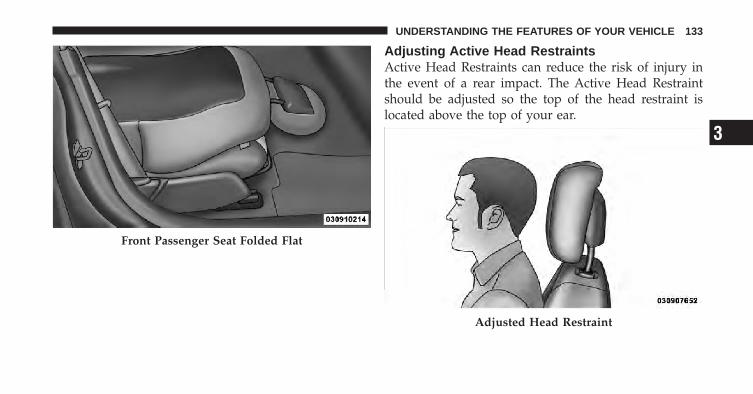
Adjusting Active Head RestraintsActive Head Restraints can reduce the risk of injury inthe event of a rear impact. The Active Head Restraintshould be adjusted so the top of the head restraint islocated above the top of your ear.
Front Passenger Seat Folded Flat
Adjusted Head Restraint
3
UNDERSTANDING THE FEATURES OF YOUR VEHICLE 133

To raise the head restraint, pull upward on the headrestraint (on some models, you may need to press thepush button). To lower the head restraint, press the pushbutton, located at the base of the head restraint, and pushdownward on the head restraint.
For comfort the Active Head Restraints can be tiltedforward and backward. To tilt the head restraint closer tothe back of your head, pull outward on the bottom of thehead restraint. Push rearward on the bottom of the headrestraint to move the head restraint away from yourhead.
Push ButtonActive Head Restraint (Normal Position)
134 UNDERSTANDING THE FEATURES OF YOUR VEHICLE
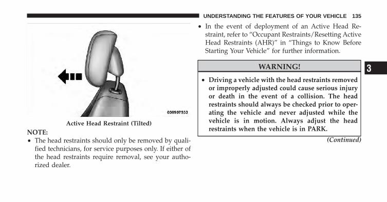
NOTE:• The head restraints should only be removed by quali-
fied technicians, for service purposes only. If either ofthe head restraints require removal, see your autho-rized dealer.
• In the event of deployment of an Active Head Re-straint, refer to “Occupant Restraints/Resetting ActiveHead Restraints (AHR)” in “Things to Know BeforeStarting Your Vehicle” for further information.
WARNING!
• Driving a vehicle with the head restraints removedor improperly adjusted could cause serious injuryor death in the event of a collision. The headrestraints should always be checked prior to oper-ating the vehicle and never adjusted while thevehicle is in motion. Always adjust the headrestraints when the vehicle is in PARK.
(Continued)
Active Head Restraint (Tilted)
3
UNDERSTANDING THE FEATURES OF YOUR VEHICLE 135

WARNING! (Continued)• Do not place items over the top of the Active Head
Restraint, such as coats, seat covers or portableDVD players. These items may interfere with theoperation of the Active Head Restraint in the eventof an accident and could result in serious injury ordeath.
• Active Head Restraints may be deployed if theyare struck by an object such as a hand, foot or loosecargo. To avoid accidental deployment of the Ac-tive Head Restraint ensure that all cargo is se-cured, as loose cargo could contact the Active HeadRestraint during sudden stops. Failure to followthis warning could cause personal injury if theActive Head Restraint is deployed.
Folding Rear SeatTo provide additional storage area, each rear seatback canbe folded forward. Pull the strap forward to move theseat forward and flat.
Folding Rear Seat
136 UNDERSTANDING THE FEATURES OF YOUR VEHICLE

To raise the seatback, pull the strap forward and lift theseatback into its upright position.
WARNING!
Be certain that the seatback is securely locked intoposition. If the seatback is not securely locked intoposition the seat will not provide the proper stabilityfor child seats and/or passengers. An improperlylatched seat could cause serious injury.
Reclining Rear Seat — If EquippedFor additional comfort, pull the strap forward justenough to release the seatback latch. Then push theseatback to a reclined position, approximately 35 degreesmaximum, and release the strap.Rear Seats Folded Flat
3
UNDERSTANDING THE FEATURES OF YOUR VEHICLE 137
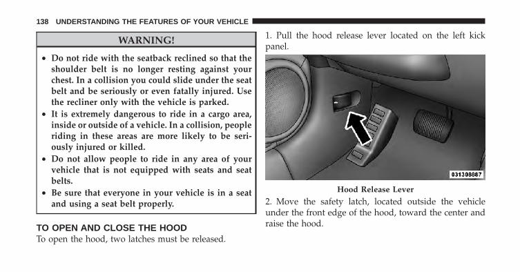
WARNING!
• Do not ride with the seatback reclined so that theshoulder belt is no longer resting against yourchest. In a collision you could slide under the seatbelt and be seriously or even fatally injured. Usethe recliner only with the vehicle is parked.
• It is extremely dangerous to ride in a cargo area,inside or outside of a vehicle. In a collision, peopleriding in these areas are more likely to be seri-ously injured or killed.
• Do not allow people to ride in any area of yourvehicle that is not equipped with seats and seatbelts.
• Be sure that everyone in your vehicle is in a seatand using a seat belt properly.
TO OPEN AND CLOSE THE HOODTo open the hood, two latches must be released.
1. Pull the hood release lever located on the left kickpanel.
2. Move the safety latch, located outside the vehicleunder the front edge of the hood, toward the center andraise the hood.
Hood Release Lever
138 UNDERSTANDING THE FEATURES OF YOUR VEHICLE
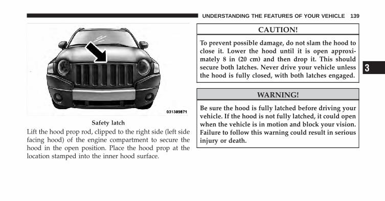
Lift the hood prop rod, clipped to the right side (left sidefacing hood) of the engine compartment to secure thehood in the open position. Place the hood prop at thelocation stamped into the inner hood surface.
CAUTION!
To prevent possible damage, do not slam the hood toclose it. Lower the hood until it is open approxi-mately 8 in (20 cm) and then drop it. This shouldsecure both latches. Never drive your vehicle unlessthe hood is fully closed, with both latches engaged.
WARNING!
Be sure the hood is fully latched before driving yourvehicle. If the hood is not fully latched, it could openwhen the vehicle is in motion and block your vision.Failure to follow this warning could result in seriousinjury or death.
Safety latch
3
UNDERSTANDING THE FEATURES OF YOUR VEHICLE 139
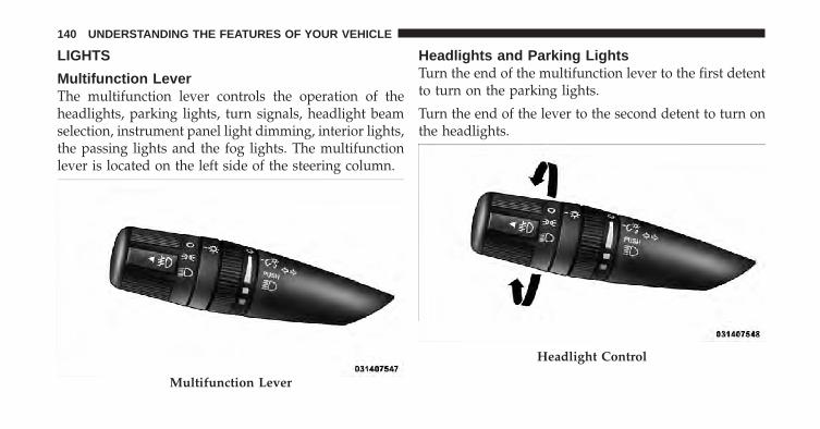
LIGHTS
Multifunction LeverThe multifunction lever controls the operation of theheadlights, parking lights, turn signals, headlight beamselection, instrument panel light dimming, interior lights,the passing lights and the fog lights. The multifunctionlever is located on the left side of the steering column.
Headlights and Parking LightsTurn the end of the multifunction lever to the first detentto turn on the parking lights.
Turn the end of the lever to the second detent to turn onthe headlights.
Multifunction Lever
Headlight Control
140 UNDERSTANDING THE FEATURES OF YOUR VEHICLE
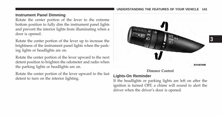
Instrument Panel DimmingRotate the center portion of the lever to the extremebottom position to fully dim the instrument panel lightsand prevent the interior lights from illuminating when adoor is opened.
Rotate the center portion of the lever up to increase thebrightness of the instrument panel lights when the park-ing lights or headlights are on.
Rotate the center portion of the lever upward to the nextdetent position to brighten the odometer and radio whenthe parking lights or headlights are on.
Rotate the center portion of the lever upward to the lastdetent to turn on the interior lighting.
Lights-On ReminderIf the headlights or parking lights are left on after theignition is turned OFF, a chime will sound to alert thedriver when the driver’s door is opened.
Dimmer Control
3
UNDERSTANDING THE FEATURES OF YOUR VEHICLE 141

Fog Lights — If EquippedThe front fog light switch is on the multifunctionlever. To activate the front fog lights, turn on theparking lights or the low beam headlights and pull
out the end of the multifunction lever.
NOTE: The fog lights will only operate with the head-lights on low beam. Selecting high beam headlights willturn off the fog lights.
Daytime Running Lights — If EquippedThe high beam lights will come on as Daytime RunningLights (lower intensity), whenever the ignition is ON, theengine is running, the headlight switch is off, the parkingbrake is off, the turn signal is off, and the shift lever is inany position except PARK.
Turn SignalsMove the multifunction lever up or down and the arrowson each side of the instrument cluster flash to showproper operation of the front and rear turn signal lights.
Front Fog Lights Control
142 UNDERSTANDING THE FEATURES OF YOUR VEHICLE
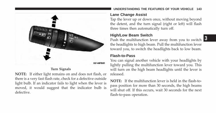
NOTE: If either light remains on and does not flash, orthere is a very fast flash rate, check for a defective outsidelight bulb. If an indicator fails to light when the lever ismoved, it would suggest that the indicator bulb isdefective.
Lane Change AssistTap the lever up or down once, without moving beyondthe detent, and the turn signal (right or left) will flashthree times then automatically turn off.
High/Low Beam SwitchPush the multifunction lever away from you to switchthe headlights to high beam. Pull the multifunction levertoward you, to switch the headlights back to low beam.
Flash-to-PassYou can signal another vehicle with your headlights bylightly pulling the multifunction lever toward you. Thiswill turn on the high beam headlights until the lever isreleased.
NOTE: If the multifunction lever is held in the flash-to-pass position for more than 30 seconds, the high beamswill shut off. If this occurs, wait 30 seconds for the nextflash-to-pass operation.
Turn Signals
3
UNDERSTANDING THE FEATURES OF YOUR VEHICLE 143

Map/Reading LightsThese lights are mounted between the sun visors abovethe rear view mirror. Each light is turned on by pressingthe button. Press the button a second time to turn thelight off. The lights also come on when a door is openedor the dimmer control is turned fully upward, past thesecond detent.
NOTE: The lights will remain on until the switch ispressed a second time, so be sure they have been turnedoff before leaving the vehicle. They will not turn offautomatically.
WINDSHIELD WIPERS AND WASHERSThe windshield wiper/washer control lever islocated on the right side of the steering column.The front wipers are operated by rotating a
switch, located on the end of the lever. For informationon the rear wiper/washer, refer to “Rear Window Fea-tures” in “Understanding the Features of Your Vehicle”.
Map/Reading Lights
144 UNDERSTANDING THE FEATURES OF YOUR VEHICLE

Windshield Wiper OperationRotate the end of the lever upward to the LO position forlow-speed wiper operation.
Rotate the end of the lever upward to the HI position forhigh-speed wiper operation.
Wiper/Washer Control Lever
Wiper Control
3
UNDERSTANDING THE FEATURES OF YOUR VEHICLE 145

Intermittent Wiper SystemUse the intermittent wiper when weather conditionsmake a single wiping cycle, with a variable pause be-tween cycles, desirable. Select the delay interval byturning the end of the lever. Rotate the end of the leverupward (clockwise) to decrease the delay time anddownward (counterclockwise) to increase the delay time.The delay can be regulated from a maximum of approxi-mately 18 seconds between cycles, to a cycle everysecond.
NOTE: The wiper delay times depend on vehicle speed.If the vehicle is moving less than 10 mph (16 km/h),delay times will be doubled.
Windshield WashersTo use the washer, pull the control lever toward you andhold while spray is desired. If the lever is pulled while inthe delay range, the wiper will operate in low-speed fortwo wipe cycles after the lever is released, and thenresume the intermittent interval previously selected.
If the lever is pulled while in the off position, the wiperswill operate for two wipe cycles, then turn off.
WARNING!
Sudden loss of visibility through the windshieldcould lead to an accident. You might not see othervehicles or other obstacles. To avoid sudden icing ofthe windshield during freezing weather, warm thewindshield with the defroster before and duringwindshield washer use.
146 UNDERSTANDING THE FEATURES OF YOUR VEHICLE

Mist FeaturePush down on the control lever to activate a single wipeto clear the windshield of road mist or spray from apassing vehicle. As long as the lever is held down, thewipers will continue to operate.
CAUTION!
In cold weather, always turn off the wiper switch andallow the wipers to return to the park position beforeturning off the engine. If the wiper switch is left onand the wipers freeze to the windshield, damage tothe wiper motor may occur when the vehicle isrestarted.
TILT STEERING COLUMNThis feature allows you to tilt the steering columnupward or downward. The tilt control handle is locatedon the left side of the steering column, below the turnsignal lever.
Mist Control
3
UNDERSTANDING THE FEATURES OF YOUR VEHICLE 147

Push down on the lever to unlock the steering column.With one hand firmly on the steering wheel, move thesteering column up or down, as desired. Push the leverup to lock the steering column firmly in place.
WARNING!
Do not adjust the steering column while driving.Adjusting the steering column while driving or driv-ing with the steering column unlocked, could causethe driver to lose control of the vehicle. Be sure thesteering column is locked before driving your ve-hicle. Failure to follow this warning may result inserious injury or death.
ELECTRONIC SPEED CONTROL — IF EQUIPPEDWhen engaged, Electronic Speed Control takes overaccelerator operation at speeds greater than 25 mph(40 km/h). The Electronic Speed Control lever is locatedon the right side of the steering wheel.
Tilting Steering Column Control
148 UNDERSTANDING THE FEATURES OF YOUR VEHICLE

NOTE: In order to ensure proper operation, the Elec-tronic Speed Control System has been designed to shutdown if multiple Speed Control functions are operated
simultaneously. If this occurs, the Electronic Speed Con-trol System can be reactivated by pushing the ElectronicSpeed Control ON/OFF button and resetting the desiredvehicle set speed.
To ActivatePush the ON/OFF button. The CRUISE indicator in theinstrument cluster will illuminate. To turn the system off,push the ON/OFF button a second time. The CRUISEindicator will turn off. The system should be turned offwhen not in use.
WARNING!
Leaving the Electronic Speed Control system onwhen not in use is dangerous. You could accidentallyset the system or cause it to go faster than you want.You could lose control and have an accident. Alwaysleave the system OFF when you are not using it.
Electronic Speed Control Lever
3
UNDERSTANDING THE FEATURES OF YOUR VEHICLE 149

To Set a Desired SpeedWhen the vehicle has reached the desired speed, pressdown on the lever and release. Release the acceleratorand the vehicle will operate at the selected speed.
NOTE: The vehicle should be traveling at a steadyspeed and on level ground before pressing the SET lever.
To DeactivateA soft tap on the brake pedal, pulling the speed controllever toward you “CANCEL”, normal braking, or clutchpressure while slowing the vehicle, will deactivate speedcontrol without erasing the set speed memory. Pressingthe ON/OFF button or turning off the ignition switcherases the set speed memory.
To Resume SpeedTo resume a previously set speed, push the RESUMEACCEL lever up and release. Resume can be used at anyspeed above 20 mph (32 km/h).
To Vary the Speed SettingWhen the Electronic Speed Control is set, you can in-crease speed by pushing up and holding the RESUMEACCEL lever. If the lever is continually held in theRESUME ACCEL position, the set speed will continue toincrease until the lever is released, then the new set speedwill be established.
Tapping RESUME ACCEL once will result in a 1 mph(1.6 km/h) speed increase. Each time the lever is tapped,speed increases so that tapping the lever three times willincrease speed by 3 mph (4.8 km/h), etc.
To decrease speed while the Electronic Speed Control isset, push down and hold the SET DECEL lever. If thelever is continually held in the SET DECEL position, theset speed will continue to decrease until the lever isreleased. Release the lever when the desired speed isreached, and the new set speed will be established.
150 UNDERSTANDING THE FEATURES OF YOUR VEHICLE

Tapping the SET DECEL lever once will result in a 1 mph(1.6 km/h) speed decrease. Each time the lever is tapped,speed decreases.
Manual TransaxlePressing the clutch pedal will disengage the ElectronicSpeed Control. A slight increase in engine RPM before thespeed control disengages is normal.
Vehicles equipped with manual transaxles may need tobe shifted into a lower gear to climb hills without speedloss.
WARNING!
Electronic Speed Control can be dangerous where thesystem cannot maintain a constant speed. Your ve-hicle could go too fast for the conditions, and youcould lose control. An accident could be the result.Do not use Electronic Speed Control in heavy trafficor on roads that are winding, icy, snow-covered orslippery.
To Accelerate for PassingPress the accelerator as you would normally. When thepedal is released, the vehicle will return to the set speed.
Using Electronic Speed Control On Hills
NOTE: The Electronic Speed Control system maintainsspeed up and down hills. A slight speed change onmoderate hills is normal.
3
UNDERSTANDING THE FEATURES OF YOUR VEHICLE 151

On steep hills a greater speed loss or gain may occur soit may be preferable to drive without Electronic SpeedControl.
WARNING!
Electronic Speed Control can be dangerous where thesystem cannot maintain a constant speed. Your ve-hicle could go too fast for the conditions, and youcould lose control. An accident could be the result.Do not use Electronic Speed Control in heavy trafficor on roads that are winding, icy, snow-covered orslippery.
GARAGE DOOR OPENER — IF EQUIPPEDHomeLink� replaces up to three remote controls (hand-held transmitters) that operate devices such as garagedoor openers, motorized gates, lighting or home securitysystems. The HomeLink� unit operates off your vehicle’sbattery.
The HomeLink� buttons that are located in the headlineror sun visor designate the three different HomeLink�channels.
NOTE: HomeLink� is disabled when the Vehicle Secu-rity Alarm is active.
HomeLink� Buttons
152 UNDERSTANDING THE FEATURES OF YOUR VEHICLE

WARNING!
• Your motorized door or gate will open and closewhile you are training the Universal Transceiver.Do not train the transceiver if people, pets or otherobjects are in the path of the door or gate. Only usethis transceiver with a garage door opener that hasa “stop and reverse” feature as required by Federalsafety standards. This includes most garage dooropener models manufactured after 1982. Do notuse a garage door opener without these safetyfeatures. Call toll-free 1–800–355–3515 or, on theInternet at www.HomeLink.com for safety infor-mation or assistance.
• Vehicle exhaust contains carbon monoxide, a dan-gerous gas. Do not run your vehicle in the garagewhile training the transceiver. Exhaust gas cancause serious injury or death.
Programming HomeLink�
Before You BeginIf you have not trained any of the HomeLink� buttons,erase all channels before you begin training.
To do this, press and hold the two outside buttons for20 seconds until the red indicator flashes.
It is recommended that a new battery be placed in thehandheld transmitter of the device that is being copied toHomeLink� for more efficient training and accuratetransmission of the radio-frequency signal.
Your vehicle should be parked outside of the garagewhen programming.
1. Turn the ignition switch to the ON/RUN position.
2. Hold the battery side of the handheld transmitteraway from the HomeLink� button you wish to program.
3
UNDERSTANDING THE FEATURES OF YOUR VEHICLE 153

Place the handheld transmitter 1–3 in (3-8 cm) away fromthe HomeLink� button you wish to program whilekeeping the indicator light in view.
3. Simultaneously press and hold both the chosenHomeLink� button and the handheld transmitter buttonuntil the HomeLink� indicator changes from a slow to arapidly blinking light, then release both the HomeLink�and handheld transmitter buttons.
Watch for the HomeLink� indicator to change flash rates.When it changes, it is programmed. It may take up to30 seconds or longer in rare cases. The garage door mayopen and close while you train.
NOTE:• Some gate operators and garage door openers may
require you to replace Step 3 with procedures noted inthe “Gate Operator/Canadian Programming” section.
• After training a HomeLink� channel, if the garagedoor does not operate with HomeLink� and the ga-rage door opener was manufactured after 1995, thegarage door opener may have a rolling code. If so,proceed to the heading “Programming A Rolling CodeSystem.”
4. Press and hold the just-trained HomeLink� buttonand observe the indicator light.
If the indicator light stays on constantly, programming iscomplete and the garage door (or device) should activatewhen the HomeLink� button is pressed.
If the indicator light blinks rapidly for two seconds, andthen turns to a constant light, continue with program-ming for a Rolling Code.
5. PROGRAMMING A ROLLING CODE SYSTEMAt the garage door opener motor (in the garage), locatethe “Learn” or “Training” button.
154 UNDERSTANDING THE FEATURES OF YOUR VEHICLE

This can usually be found where the hanging antennawire is attached to the garage door opener motor (it isNOT the button normally used to open and close thedoor).
6. Firmly press and release the LEARN or TRAININGbutton. The name and color of the button may vary bymanufacturer.
NOTE: You have 30 seconds in which to initiate the nextstep after the LEARN button has been pressed.
7. Return to the vehicle and press the programmedHomeLink� button twice (holding the button for twoseconds each time). If the device is plugged in andactivates, programming is complete.
If the device does not activate, press the button a thirdtime (for two seconds) to complete the training.
If you have any problems, or require assistance, pleasecall toll-free 1–800–355–3515 or, on the Internet atwww.HomeLink.com for information or assistance.
To program the remaining two HomeLink� buttons,repeat each step for each remaining button. DO NOTerase the channels.
1 — Garage Door Opener2 — Training Button
3
UNDERSTANDING THE FEATURES OF YOUR VEHICLE 155

Gate Operator/Canadian ProgrammingCanadian radio-frequency laws require transmitter sig-nals to “time-out” (or quit) after several seconds oftransmission – which may not be long enough forHomeLink� to pick up the signal during programming.Similar to this Canadian law, some U.S. gate operators aredesigned to “time-out” in the same manner.
It may be helpful to unplug the device during the cyclingprocess to prevent possible overheating of the garagedoor or gate motor.
If you are having difficulties programming a garage dooropener or a gate operator, replace “ProgrammingHomeLink�” Step 3 with the following:
3. Continue to press and hold the HomeLink� button,while you press and release (“cycle”), your handheldtransmitter every two seconds until HomeLink� has
successfully accepted the frequency signal. The indica-tor light will flash slowly and then rapidly when fullytrained.
If you unplugged the device for training, plug it back inat this time.
Then proceed with Step 4 under “ProgrammingHomeLink�” earlier in this section.
Using HomeLink�To operate, press and release the programmedHomeLink� button. Activation will now occur for thetrained device (i.e., garage door opener, gate operator,Security system, entry door lock, home/office lighting,etc.,). The handheld transmitter of the device may also beused at any time.
156 UNDERSTANDING THE FEATURES OF YOUR VEHICLE
Reprogramming A Single HomeLink� ButtonTo reprogram a channel that has been previously trained,follow these steps:
1. Turn the ignition switch to the ON/RUN position.
2. Press and hold the desired HomeLink� button untilthe indicator light begins to flash after 20 seconds. Do notrelease the button.
3. Without releasing the button, proceed with Program-ming HomeLink� Step 2 and follow all remaining steps.
SecurityIt is advised to erase all channels before you sell or turnin your vehicle.
To do this, press and hold the two outside buttons for20 seconds until the red indicator flashes. Note that allchannels will be erased. Individual channels cannot beerased.
The HomeLink� Universal Transceiver is disabled whenthe Vehicle Security Alarm is active.
Troubleshooting TipsIf you are having trouble programming HomeLink�, hereare some of the most common solutions:
• Replace the battery in the original transmitter.
• Press the LEARN button on the Garage Door Openerto complete the training for a Rolling Code.
• Did you unplug the device for training, and rememberto plug it back in?
If you have any problems, or require assistance, pleasecall toll-free 1–800–355–3515 or, on the Internet atwww.HomeLink.com for information or assistance.
3
UNDERSTANDING THE FEATURES OF YOUR VEHICLE 157

General InformationThis device complies with FCC rules Part 15 and IndustryCanada RSS-210. Operation is subject to the followingtwo conditions:
1. This device may not cause harmful interference.
2. This device must accept any interference that may bereceived including interference that may cause undesiredoperation.
NOTE: The transmitter has been tested and it complieswith FCC and IC rules. Changes or modifications notexpressly approved by the party responsible for compli-ance could void the user’s authority to operate thedevice.
The term IC before the certification/registration numberonly signifies that Industry Canada technical specifica-tions were met.
POWER SUNROOF — IF EQUIPPEDThe power sunroof switch is located in the reading light.
Power Sunroof Switch
158 UNDERSTANDING THE FEATURES OF YOUR VEHICLE

WARNING!
• Never leave children in a vehicle with the key inthe ignition switch. Occupants, particularly unat-tended children, can become entrapped by thepower sunroof while operating the power sunroofswitch. Such entrapment may result in seriousinjury or death.
• In an accident, there is a greater risk of beingthrown from a vehicle with an open sunroof. Youcould also be seriously injured or killed. Alwaysfasten your seat belt properly and make sure allpassengers are properly secured too.
• Do not allow small children to operate the sun-roof. Never allow your fingers, other body parts, orany object to project through the sunroof opening.Injury may result.
Opening the Sunroof
Manual ModeTo open the sunroof, press and hold the switch rearwardto full open. Any release of the switch will stop themovement and the sunroof will remain in a partial opencondition until the switch is pushed and held rearwardagain.
Express ModePress the switch rearward and release, and the sunroofwill open automatically from any position. The sunroofwill open fully, and stop automatically, this is called“Express Open”. During Express Open operation anymovement of the sunroof switch will stop the sunroof.
Closing the Sunroof
Manual ModeTo close the sunroof, press and hold the switch in theforward position. Again, any release of the switch will
3
UNDERSTANDING THE FEATURES OF YOUR VEHICLE 159
stop the movement and the sunroof will remain in apartial close condition until the switch is pushed andheld forward again. To ensure sunroof is fully closed,press and hold switch until sunroof has completelystopped moving.
Express ModePress the switch forward and release, and the sunroofwill close automatically from any position. The sunroofwill close fully, and stop automatically, this is called“Express Close”. During Express Close operation, anymovement of the switch will stop the sunroof.
Pinch Protect FeatureThis feature will detect an obstruction in the opening ofthe sunroof during Express Close operation. If an ob-struction in the path of the sunroof is detected, thesunroof will automatically retract. Remove obstructionand press the switch forward and release to ExpressClose.
Pinch Protect OverrideIf a known obstruction (ice, debris, etc.) prevents closing,press the switch forward and hold for two seconds afterthe reversal occurs. This allows the sunroof to movetowards the close position.
NOTE: Pinch protection is disabled while the switch ispressed.
Venting Sunroof — ExpressPress and hold the “Vent” button, and the sunroof willopen to the vent position. This is called “Express Vent”,and will occur regardless of the sunroof position. DuringExpress Vent operation, any movement of the switch willstop the sunroof.
Sunshade OperationThe sunshade can be opened manually. However, thesunshade will open automatically as the sunroof opens.
NOTE: The sunshade cannot be closed if the sunroof isopen.
160 UNDERSTANDING THE FEATURES OF YOUR VEHICLE

Wind BuffetingWind buffeting can be described as the perception ofpressure on the ears or a helicopter-type sound in theears. Your vehicle may exhibit wind buffeting with thewindows down, or the sunroof (if equipped) in certainopen or partially open positions. This is a normal occur-rence and can be minimized. If the buffeting occurs withthe rear windows open, open the front and rear windowstogether to minimize the buffeting. If the buffeting occurswith the sunroof open, adjust the sunroof opening tominimize the buffeting or open any window.
Sunroof MaintenanceUse only a non-abrasive cleaner and a soft cloth to cleanthe glass panel.
Ignition Off OperationThe sunroof will also operate up to 45 seconds after theignition has been turned OFF. The sunroof operation willbe canceled if either of the front doors are opened duringthe 45 second time period.
ELECTRICAL POWER OUTLETSThere is a standard 12 Volt (13 Amp) power outlet locatedin the instrument panel for added convenience. Thispower outlet can power cellular phones, electronics andother low power devices.
12 Volt Power Outlet
3
UNDERSTANDING THE FEATURES OF YOUR VEHICLE 161
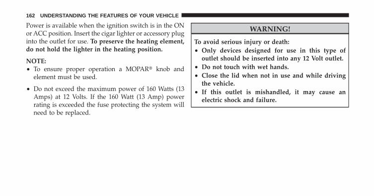
Power is available when the ignition switch is in the ONor ACC position. Insert the cigar lighter or accessory pluginto the outlet for use. To preserve the heating element,do not hold the lighter in the heating position.
NOTE:• To ensure proper operation a MOPAR� knob and
element must be used.
• Do not exceed the maximum power of 160 Watts (13Amps) at 12 Volts. If the 160 Watt (13 Amp) powerrating is exceeded the fuse protecting the system willneed to be replaced.
WARNING!
To avoid serious injury or death:• Only devices designed for use in this type of
outlet should be inserted into any 12 Volt outlet.• Do not touch with wet hands.• Close the lid when not in use and while driving
the vehicle.• If this outlet is mishandled, it may cause an
electric shock and failure.
162 UNDERSTANDING THE FEATURES OF YOUR VEHICLE

CAUTION!
• Many accessories that can be plugged in drawpower from the vehicle’s battery, even when not inuse (i.e., cellular phones, etc.). Eventually, ifplugged in long enough, the vehicle’s battery willdischarge sufficiently to degrade battery lifeand/or prevent the engine from starting.
• Accessories that draw higher power (i.e., coolers,vacuum cleaners, lights, etc.) will degrade thebattery even more quickly. Only use these inter-mittently and with great caution.
• After the use of high power draw accessories, orlong periods of the vehicle not being started (withaccessories still plugged in), the vehicle must bedriven a sufficient length of time to allow thegenerator to recharge the vehicle’s battery.
POWER INVERTER — IF EQUIPPEDA 115 Volt (150 Watt) AC power inverter is located on thefront of the center console for added convenience. Thisoutlet can power cellular phones, electronics and otherlow power devices requiring power up to 150 Watts.Certain high-end video games, such as Playstation3 andXBox360 will exceed this power limit, as will most powertools.
The power inverter is designed with built-in overloadprotection. If the power rating of 150 Watts is exceeded,the power inverter will automatically shut down. Oncethe electrical device has been removed from the outlet theinverter should automatically reset. If the power ratingexceeds approximately 170 Watts, the power invertermay have to be reset manually. To reset the inverter
3
UNDERSTANDING THE FEATURES OF YOUR VEHICLE 163

manually, unplug the device and plug it in again. Toavoid overloading the circuit, check the power ratings onelectrical devices prior to using the inverter.
WARNING!
To avoid serious injury or death:• Do not use a three-prong adaptor.• Do not insert any objects into the receptacles.• Do not touch with wet hands.• Close the lid when not in use.• If this outlet is mishandled, it may cause an
electric shock and failure.
CAUTION!
• Many accessories that can be plugged in drawpower from the vehicle’s battery, even when not inuse (i.e., cellular phones, etc.). Eventually, ifplugged in long enough, the vehicle’s battery willdischarge sufficiently to degrade battery lifeand/or prevent engine starting.
(Continued)
115 Volt Power Outlet
164 UNDERSTANDING THE FEATURES OF YOUR VEHICLE

CAUTION! (Continued)• Accessories that draw higher power (i.e., coolers,
vacuum cleaners, lights, etc.) will degrade thebattery even more quickly. Only use these inter-mittently and with great caution.
• After the use of high power draw accessories, orlong periods of the vehicle not being started (withaccessories still plugged in), the vehicle must bedriven a sufficient length of time to allow thegenerator to recharge the vehicle’s battery.
CUPHOLDERSYour vehicle is equipped with four cupholders. There aretwo illuminated cupholders located in the front.
Illuminated Front Cupholders
3
UNDERSTANDING THE FEATURES OF YOUR VEHICLE 165
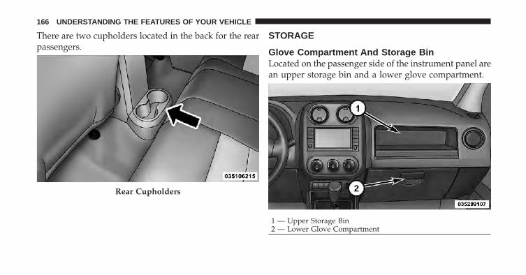
There are two cupholders located in the back for the rearpassengers.
STORAGE
Glove Compartment And Storage BinLocated on the passenger side of the instrument panel arean upper storage bin and a lower glove compartment.
Rear Cupholders
1 — Upper Storage Bin2 — Lower Glove Compartment
166 UNDERSTANDING THE FEATURES OF YOUR VEHICLE
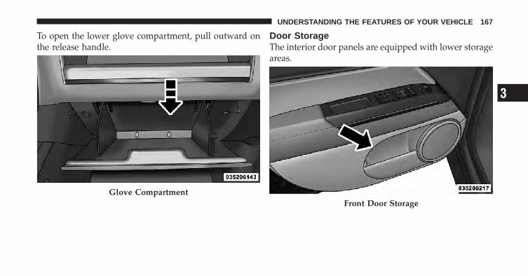
To open the lower glove compartment, pull outward onthe release handle.
Door StorageThe interior door panels are equipped with lower storageareas.
Glove CompartmentFront Door Storage
3
UNDERSTANDING THE FEATURES OF YOUR VEHICLE 167

CONSOLE FEATURESThe floor console contains both an upper and lowerstorage compartment.
To open the upper storage compartment, push inward onthe upper handle to unlatch the upper lid and lift the lidopen.
To open the lower storage compartment, lift upward onthe lower handle to unlatch the lower storage compart-ment and lift the lid open.
Rear Door Storage Upper Storage Compartment
168 UNDERSTANDING THE FEATURES OF YOUR VEHICLE

WARNING!
Do not operate this vehicle with a console compart-ment lid in the open position. Cellular phones, musicplayers, and other handheld electronic devicesshould be stowed while driving. Use of these deviceswhile driving can cause an accident due to distrac-tion, resulting in death or injury.
CARGO AREA FEATURES
Cargo Light/Removable Self-RechargingFlashlightThe dual-function light is mounted in the headlinerabove the cargo area to illuminate the cargo area, andpart of it snaps out of the bezel to serve as a flashlightwhen needed. The flashlight features two bright LEDlight bulbs and is powered by rechargeable lithiumbatteries that recharge when snapped back into place forconvenience.
Lower Storage Compartment
3
UNDERSTANDING THE FEATURES OF YOUR VEHICLE 169
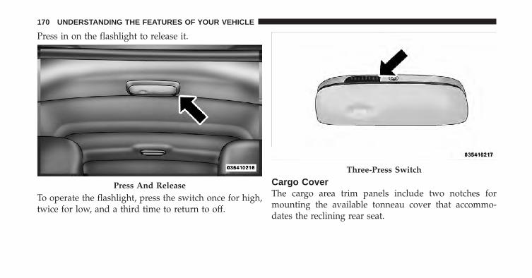
Press in on the flashlight to release it.
To operate the flashlight, press the switch once for high,twice for low, and a third time to return to off.
Cargo CoverThe cargo area trim panels include two notches formounting the available tonneau cover that accommo-dates the reclining rear seat.
Press And Release
Three-Press Switch
170 UNDERSTANDING THE FEATURES OF YOUR VEHICLE

To install the Cargo Cover, insert either end of the coverinto one of the two notches located in the rear trimpanels. With one of the cover ends installed, push inwardon the opposite end and install it into the same notchlocation of the rear trim panel.
Using the handle, pull the cover toward you and guidethe rear cover posts into the guides located on both sidesof the rear trim panel.
Rear Trim Notches
Cargo Cover Guides
3
UNDERSTANDING THE FEATURES OF YOUR VEHICLE 171

WARNING!
In an accident a cargo cover loose in the vehicle couldcause injury. It could fly around in a sudden stop andstrike someone in the vehicle. Do not store the cargocover on the cargo floor or in the passenger compart-ment. Remove the cover from the vehicle when takenfrom its mounting. Do not store in the vehicle.
Removable Load FloorThe cargo area load floor is removable and can bewashed with mild soap and water.
Cargo Load Floor
172 UNDERSTANDING THE FEATURES OF YOUR VEHICLE

Cargo Tie-Down LoopsThere are four D-rings installed in the cargo area forsecuring cargo.
WARNING!
• Cargo tie-down loops are not safe anchors for achild seat tether strap. In a sudden stop or collisiona loop could pull loose and allow the child seat tocome loose. A child could be badly injured. Useonly the anchors provided for child seat tethers.
• The weight and position of cargo and passengerscan change the vehicle center of gravity and ve-hicle handling. To avoid loss of control resultingin personal injury, follow these guidelines forloading your vehicle:
• Always place cargo evenly on the cargo floor. Putheavier objects as low and as far forward aspossible.
(Continued)D-Rings
3
UNDERSTANDING THE FEATURES OF YOUR VEHICLE 173

WARNING! (Continued)• Place as much cargo as possible in front of the rear
axle. Too much weight or improperly placedweight over or behind the rear axle can cause therear of the vehicle to sway.
• Do not pile luggage or cargo higher than the top ofthe seatback. This could impair visibility or be-come a dangerous projectile in a sudden stop orcollision.
• To help protect against personal injury, passengersshould not be seated in the rear cargo area. Therear cargo space is intended for load carryingpurposes only, not for passengers, who should sitin seats and use seat belts.
Fold Down Speakers — If EquippedWhen the liftgate is open, the speakers can swing downoff the trim panel to face rearward, for tailgating andother activities.
REAR WINDOW FEATURES
Rear Window Wiper/WasherThe rear wiper/washer is controlled by a rotary switchlocated on the center portion of the control lever. Thecontrol lever is located on the right side of the steeringcolumn.
Fold-Down Speakers
174 UNDERSTANDING THE FEATURES OF YOUR VEHICLE
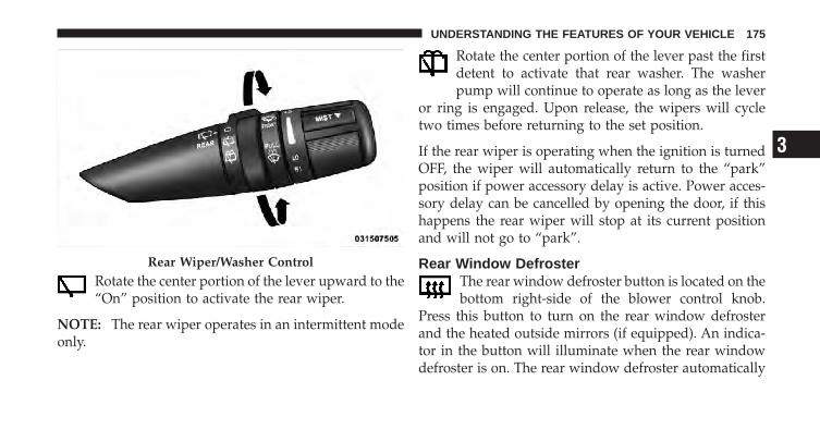
Rotate the center portion of the lever upward to the“On” position to activate the rear wiper.
NOTE: The rear wiper operates in an intermittent modeonly.
Rotate the center portion of the lever past the firstdetent to activate that rear washer. The washerpump will continue to operate as long as the lever
or ring is engaged. Upon release, the wipers will cycletwo times before returning to the set position.
If the rear wiper is operating when the ignition is turnedOFF, the wiper will automatically return to the “park”position if power accessory delay is active. Power acces-sory delay can be cancelled by opening the door, if thishappens the rear wiper will stop at its current positionand will not go to “park”.
Rear Window DefrosterThe rear window defroster button is located on thebottom right-side of the blower control knob.
Press this button to turn on the rear window defrosterand the heated outside mirrors (if equipped). An indica-tor in the button will illuminate when the rear windowdefroster is on. The rear window defroster automatically
Rear Wiper/Washer Control
3
UNDERSTANDING THE FEATURES OF YOUR VEHICLE 175

turns off after approximately 10 minutes. For an addi-tional five minutes of operation, press the button asecond time.
NOTE: To prevent excessive battery drain, use the rearwindow defroster only when the engine is operating.
CAUTION!
Failure to follow these cautions can cause damage tothe heating elements:• Use care when washing the inside of the rear
window. Do not use abrasive window cleaners onthe interior surface of the window. Use a soft clothand a mild washing solution, wiping parallel tothe heating elements. Labels can be peeled offafter soaking with warm water.
(Continued)
CAUTION! (Continued)• Do not use scrapers, sharp instruments, or abra-
sive window cleaners on the interior surface of thewindow.
• Keep all objects a safe distance from the window.
ROOF LUGGAGE RACK — IF EQUIPPEDAn optional authorized-dealer installed roof rack withcross rails is available through MOPAR� for added cargoversatility.
176 UNDERSTANDING THE FEATURES OF YOUR VEHICLE

UNDERSTANDING YOUR INSTRUMENT PANEL
CONTENTS
� Instrument Panel Features . . . . . . . . . . . . . . . 181
� Instrument Cluster . . . . . . . . . . . . . . . . . . . . 182
� Instrument Cluster Descriptions . . . . . . . . . . . 183
� Electronic Vehicle Information Center (EVIC) —If Equipped . . . . . . . . . . . . . . . . . . . . . . . . . . 196
▫ Engine Oil Change Indicator System —If Equipped . . . . . . . . . . . . . . . . . . . . . . . . 198
▫ EVIC Functions . . . . . . . . . . . . . . . . . . . . . 199
▫ Compass/Temperature/Audio . . . . . . . . . . . 200
▫ Average Fuel Economy . . . . . . . . . . . . . . . . 200
▫ Distance To Empty (DTE) . . . . . . . . . . . . . . 200
▫ Tire Pressure Monitor (TPM) . . . . . . . . . . . . 200
▫ Elapsed Time . . . . . . . . . . . . . . . . . . . . . . . 201
▫ Personal Settings(Customer-Programmable Features) . . . . . . . 201
� Media Center 230 (REQ) — AM/FM StereoRadio And 6–Disc CD/DVD Changer(MP3/WMA AUX Jack) . . . . . . . . . . . . . . . . . . 206
▫ Operating Instructions - Radio Mode . . . . . . 206
4

▫ Operation Instructions - (Disc Mode For CDAnd MP3/WMA Audio Play, DVD-Video) . . . 214
▫ Notes On Playing MP3/WMA Files . . . . . . . 216
▫ List Button(Disc Mode For MP3/WMA Play) . . . . . . . . . 219
▫ Info Button(Disc Mode For MP3/WMA Play) . . . . . . . . . 219
� Media Center 730N/430 (RER/REN/RBZ) —AM/FM Stereo Radio And CD/DVD/HDD/NAV — If Equipped . . . . . . . . . . . . . . . . . . . . 221
▫ Operating Instructions — Voice CommandSystem — If Equipped . . . . . . . . . . . . . . . . . 222
▫ Operating Instructions —Uconnect™ phone — If Equipped . . . . . . . . 222
▫ Clock Setting Procedure — RBZ Radio . . . . . 222
▫ Clock Setting Procedure —RER/REN Radio . . . . . . . . . . . . . . . . . . . . . 224
� Media Center 130 (RES) — AM/FM StereoRadio With CD Player (MP3 AUX Jack). . . . . . . 226
▫ Operating Instructions — Radio Mode . . . . . 226
▫ Operation Instructions — CD Mode For CDAnd MP3 Audio Play . . . . . . . . . . . . . . . . . 229
▫ Notes On Playing MP3 Files . . . . . . . . . . . . 232
▫ Operation Instructions - Auxiliary Mode . . . . 234
� Media Center 130 (RES/RSC) — AM/FMStereo Radio With CD Player (MP3 AUX Jack)And Sirius Radio . . . . . . . . . . . . . . . . . . . . . . 235
▫ Operating Instructions — Radio Mode . . . . . 235
▫ Operation Instructions — CD Mode For CDAnd MP3 Audio Play . . . . . . . . . . . . . . . . . 241
178 UNDERSTANDING YOUR INSTRUMENT PANEL
▫ Notes On Playing MP3 Files . . . . . . . . . . . . 243
▫ List Button (CD Mode For MP3 Play) . . . . . . 245
▫ Info Button (CD Mode For MP3 Play) . . . . . . 246
� Universal Consumer Interface (UCI) —If Equipped . . . . . . . . . . . . . . . . . . . . . . . . . . 247
▫ Connecting The iPod� . . . . . . . . . . . . . . . . . 247
▫ Using This Feature . . . . . . . . . . . . . . . . . . . 248
▫ Controlling The iPod� UsingRadio Buttons . . . . . . . . . . . . . . . . . . . . . . . 248
▫ Play Mode . . . . . . . . . . . . . . . . . . . . . . . . . 248
▫ List Or Browse Mode . . . . . . . . . . . . . . . . . 250
� Uconnect™ Multimedia (Satellite Radio) —If Equipped (REN/REQ/RER/RES/REU/RBZRadios Only) . . . . . . . . . . . . . . . . . . . . . . . . . 252
▫ System Activation . . . . . . . . . . . . . . . . . . . . 252
▫ Electronic Serial Number/SiriusIdentification Number (ESN/SID) . . . . . . . . . 252
▫ Selecting Uconnect™ Multimedia (Satellite)Mode . . . . . . . . . . . . . . . . . . . . . . . . . . . . . 253
▫ Satellite Antenna . . . . . . . . . . . . . . . . . . . . . 253
▫ Reception Quality . . . . . . . . . . . . . . . . . . . . 253
▫ Operating Instructions — Uconnect™Multimedia (Satellite) Mode . . . . . . . . . . . . . 254
▫ Operating Instructions — Uconnect™ phone(If Equipped) . . . . . . . . . . . . . . . . . . . . . . . 257
4
UNDERSTANDING YOUR INSTRUMENT PANEL 179

▫ Operating Instructions — VideoEntertainment System(VES)™ (If Equipped) . . . . . . . . . . . . . . . . . 257
� Remote Sound System Controls —If Equipped . . . . . . . . . . . . . . . . . . . . . . . . . . 257
▫ Radio Operation . . . . . . . . . . . . . . . . . . . . . 258
▫ CD Player . . . . . . . . . . . . . . . . . . . . . . . . . 258
� CD/DVD Disc Maintenance . . . . . . . . . . . . . . 258
� Radio Operation And Cellular Phones . . . . . . . 259
� Climate Controls . . . . . . . . . . . . . . . . . . . . . . 259
▫ Manual Heating And Air Conditioning . . . . . 260
▫ Automatic Temperature Control (ATC) —If Equipped . . . . . . . . . . . . . . . . . . . . . . . . 264
▫ Operating Tips . . . . . . . . . . . . . . . . . . . . . . 270
180 UNDERSTANDING YOUR INSTRUMENT PANEL
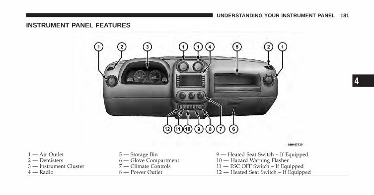
INSTRUMENT PANEL FEATURES
1 — Air Outlet 5 — Storage Bin 9 — Heated Seat Switch – If Equipped2 — Demisters 6 — Glove Compartment 10 — Hazard Warning Flasher3 — Instrument Cluster 7 — Climate Controls 11 — ESC OFF Switch – If Equipped4 — Radio 8 — Power Outlet 12 — Heated Seat Switch – If Equipped
4
UNDERSTANDING YOUR INSTRUMENT PANEL 181
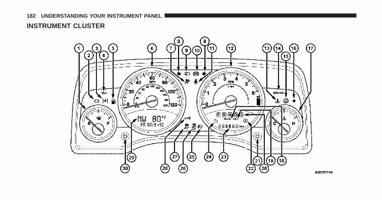
INSTRUMENT CLUSTER
182 UNDERSTANDING YOUR INSTRUMENT PANEL
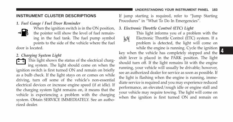
INSTRUMENT CLUSTER DESCRIPTIONS
1. Fuel Gauge / Fuel Door ReminderWhen the ignition switch is in the ON position,the pointer will show the level of fuel remain-ing in the fuel tank. The fuel pump symbolpoints to the side of the vehicle where the fuel
door is located.
2. Charging System LightThis light shows the status of the electrical charg-ing system. The light should come on when the
ignition switch is first turned ON and remain on brieflyas a bulb check. If the light stays on or comes on whiledriving, turn off some of the vehicle’s non-essentialelectrical devices or increase engine speed (if at idle). Ifthe charging system light remains on, it means that thevehicle is experiencing a problem with the chargingsystem. Obtain SERVICE IMMEDIATELY. See an autho-rized dealer.
If jump starting is required, refer to “Jump StartingProcedures” in “What To Do In Emergencies”.
3. Electronic Throttle Control (ETC) LightThis light informs you of a problem with theElectronic Throttle Control (ETC) system. If aproblem is detected, the light will come onwhile the engine is running. Cycle the ignition
key when the vehicle has completely stopped and theshift lever is placed in the PARK position. The lightshould turn off. If the light remains lit with the enginerunning, your vehicle will usually be drivable; however,see an authorized dealer for service as soon as possible. Ifthe light is flashing when the engine is running, imme-diate service is required and you may experience reducedperformance, an elevated/rough idle or engine stall andyour vehicle may require towing. The light will come onwhen the ignition is first turned ON and remain on
4
UNDERSTANDING YOUR INSTRUMENT PANEL 183

briefly as a bulb check. If the light does not come onduring starting, have the system checked by an autho-rized dealer.
4. Oil Pressure Warning LightThis light indicates low engine oil pressure. Thelight should turn on momentarily when the engine
is started. If the light turns on while driving, stop thevehicle and shut off the engine as soon as possible. Achime will sound for four minutes when this light turnson.
Do not operate the vehicle until the cause is corrected.This light does not indicate how much oil is in the engine.The engine oil level must be checked under the hood.
5. Low Fuel LightWhen the fuel level reaches approximately 2.0 gal(7.8 L) this light will turn on, and remain on untilfuel is added.
6. SpeedometerThe Speedometer shows the vehicle speed in miles perhour and/or kilometers per hour (mph/kph).
7. Airbag Warning LightThis light turns on and remains on for six toeight seconds as a bulb check when the ignitionswitch is first turned ON. If the light is not onduring starting, stays on, or turns on while
driving, have the system inspected by an authorizeddealer as soon as possible. Refer to “Occupant Restraints”in “Things To Know Before Starting Your Vehicle” forfurther information.
8. Turn Signal IndicatorsThe arrow will flash with the exterior turn signalwhen the turn signal lever is operated.
If the vehicle electronics sense that the vehicle hastraveled about 1 mile (1.6 km) with the turn signals on, a
184 UNDERSTANDING YOUR INSTRUMENT PANEL

continuous chime will sound to alert you to turn thesignals off. If either indicator flashes at a rapid rate, checkfor a defective outside light bulb.
9. High Beam IndicatorThis indicator shows that the high beam head-lights are on. Push the multifunction lever forward
to switch the headlights to high beam, and pull towardyourself (normal position) to return to low beam.
10. Anti-Lock Brake (ABS) LightThis light monitors the Anti-Lock Brake System(ABS). The light will turn on when the ignitionswitch is turned to the ON position and maystay on for as long as four seconds.
If the ABS light remains on or turns on while driving, itindicates that the Anti-Lock portion of the brake systemis not functioning and that service is required. However,the conventional brake system will continue to operatenormally if the BRAKE warning light is not on.
If the ABS light is on, the brake system should be servicedas soon as possible to restore the benefits of Anti-Lockbrakes. If the ABS light does not turn on when theignition switch is turned to the ON position, have thelight inspected by an authorized dealer.
11. Seat Belt Reminder LightWhen the ignition switch is first turned ON, thislight will turn on for five to eight seconds as a bulbcheck. During the bulb check, if the driver’s seat
belt is unbuckled, a chime will sound. After the bulbcheck or when driving, if the driver’s seat belt remainsunbuckled, the Seat Belt Reminder Light will illuminateand the chime will sound. Refer to “Occupant Restraints”in “Things To Know Before Starting Your Vehicle” forfurther information.
4
UNDERSTANDING YOUR INSTRUMENT PANEL 185

12. TachometerThe white area of the scale shows the permissible enginerevolutions-per-minute (RPM x 1000) for each gear range.Before reaching the red area, ease up on the accelerator toprevent engine damage.
13. Engine Temperature Warning LightThis light warns of an overheated engine condi-tion. As temperatures rise and the gauge ap-proaches H, this indicator will illuminate and a
single chime will sound after reaching a set threshold.Further overheating will cause the temperature gauge topass H, the indicator will continuously flash and acontinuous chime will occur until the engine is allowedto cool.
If the light turns on while driving, safely pull over andstop the vehicle. If the A/C system is on, turn it off. Also,shift the transmission into NEUTRAL and idle the ve-hicle. If the temperature reading does not return to
normal, turn the engine off immediately and call forservice. Refer to “If Your Engine Overheats” in “What ToDo In Emergencies” for further information.
14. Brake Warning LightThis light monitors various brake functions,including brake fluid level and parking brakeapplication. If the brake light turns on, it mayindicate that the parking brake is applied, that
the brake fluid level is low, or that there is a problem withthe anti-lock brake system reservoir.
If the light remains on when the parking brake has beendisengaged, and the fluid level is at the full mark on themaster cylinder reservoir, it indicates a possible brakehydraulic system malfunction or that a problem with theBrake Booster has been detected by the Anti-Lock BrakeSystem (ABS) / Electronic Stability Control (ESC) system.In this case, the light will remain on until the conditionhas been corrected. If the problem is related to the brake
186 UNDERSTANDING YOUR INSTRUMENT PANEL
booster, the ABS pump will run when applying the brakeand a brake pedal pulsation may be felt during each stop.
The dual brake system provides a reserve braking capac-ity in the event of a failure to a portion of the hydraulicsystem. A leak in either half of the dual brake system isindicated by the Brake Warning Light, which will turn onwhen the brake fluid level in the master cylinder hasdropped below a specified level.
The light will remain on until the cause is corrected.
NOTE: The light may flash momentarily during sharpcornering maneuvers, which change fluid level condi-tions. The vehicle should have service performed, andthe brake fluid level checked.
If brake failure is indicated, immediate repair is neces-sary.
WARNING!
Driving a vehicle with the red brake light on isdangerous. Part of the brake system may have failed.It will take longer to stop the vehicle. You could havean accident. Have the vehicle checked immediately.
Vehicles equipped with the Anti-Lock Brake System(ABS), are also equipped with Electronic Brake ForceDistribution (EBD). In the event of an EBD failure, theBrake Warning Light will turn on along with the ABSLight. Immediate repair to the ABS system is required.
Operation of the Brake Warning Light can be checked byturning the ignition switch from the OFF position to theON position. The light should illuminate for approxi-mately two seconds. The light should then turn off unlessthe parking brake is applied or a brake fault is detected.If the light does not illuminate, have the light inspectedby an authorized dealer.
4
UNDERSTANDING YOUR INSTRUMENT PANEL 187
The light also will turn on when the parking brake isapplied with the ignition switch in the ON position.
NOTE: This light shows only that the parking brake isapplied. It does not show the degree of brake application.
15. Transmission Temperature Warning LightDuring sustained high speed driving or trailertowing up long grades on hot days, the auto-matic transaxle oil may become too hot. Whenthe transmission overheat warning light turns
on, you will experience reduced vehicle performanceuntil the automatic transaxle cools down. Once thetransaxle has cooled down and the light turns off, youmay continue to drive normally. If the high speed ismaintained, the overheating will continue to occur.
If the overheating continues, it may become necessary tostop the vehicle and run the engine at idle with thetransaxle in NEUTRAL until the light turns off.
CAUTION!
Continuous driving with the Transmission Tempera-ture Warning Light illuminated will eventually causesevere transmission damage or transmission failure.
WARNING!
In some circumstances a Transmission TemperatureWarning Light, under continued operation, couldcause the fluid to boil over, come in contact with hotengine or exhaust components and cause a fire.
16. Vehicle Security Light — If EquippedThis light will flash at a fast rate for approxi-mately 16 seconds, when the vehicle securityalarm is arming, and then will flash slowlyuntil the vehicle is disarmed.
188 UNDERSTANDING YOUR INSTRUMENT PANEL
17. Temperature GaugeThe temperature gauge shows engine coolant tempera-ture. Any reading within the normal range indicates thatthe engine cooling system is operating satisfactorily.
The gauge pointer will likely indicate a higher tempera-ture when driving in hot weather, up mountain grades,or when towing a trailer. It should not be allowed toexceed the upper limits of the normal operating range.
CAUTION!
Driving with a hot engine cooling system coulddamage your vehicle. If temperature gauge reads “H”pull over and stop the vehicle. Idle the vehicle withthe air conditioner turned off until the pointer dropsback into the normal range. If the pointer remains onthe “H” and you hear continuous chimes, turn theengine off immediately, and call an authorized deal-ership for service.
WARNING!
A hot engine cooling system is dangerous. You orothers could be badly burned by steam or boilingcoolant. You may want to call an authorized dealer-ship for service if your vehicle overheats. If youdecide to look under the hood yourself, see “Main-taining Your Vehicle”. Follow the warnings under theCooling System Pressure Cap paragraph.
18. Cruise Indicator — If EquippedThis indicator shows that the Electronic SpeedControl System is ON.
19. 4WD Indicator — If EquippedThis light indicates the vehicle is in 4WD.
4
UNDERSTANDING YOUR INSTRUMENT PANEL 189

20. Shift Lever IndicatorThe Shift Lever Indicator is self-contained within theinstrument cluster. It displays the gear position of theautomatic transmission.
NOTE: You must apply the brakes before shifting fromPARK.
21. Odometer/Trip Odometer Reset ButtonPress this button to change the display from odometer toeither of the two trip odometer settings. Trip A or Trip Bwill appear when in the trip odometer mode. Push in andhold the button for two seconds to reset the trip odometerto 0 miles or kilometers. The odometer must be in Tripmode to reset.
22. Tire Pressure Monitoring Telltale LightEach tire, including the spare (if provided),should be checked monthly, when cold andinflated to the inflation pressure recommendedby the vehicle manufacturer on the vehicle
placard or tire inflation pressure label. (If your vehiclehas tires of a different size than the size indicated on thevehicle placard or tire inflation pressure label, you shoulddetermine the proper tire inflation pressure for thosetires.)
As an added safety feature, your vehicle has beenequipped with a Tire Pressure Monitoring System(TPMS) that illuminates a low tire pressure telltale whenone or more of your tires is significantly under-inflated.Accordingly, when the low tire pressure telltale illumi-nates, you should stop and check your tires as soon aspossible, and inflate them to the proper pressure. Drivingon a significantly under-inflated tire causes the tire tooverheat and can lead to tire failure. Under-inflation alsoreduces fuel efficiency and tire tread life, and may affectthe vehicle’s handling and stopping ability.
Please note that the TPMS is not a substitute for propertire maintenance, and it is the driver’s responsibility to
190 UNDERSTANDING YOUR INSTRUMENT PANEL
maintain correct tire pressure, even if under-inflation hasnot reached the level to trigger illumination of the TPMSlow tire pressure telltale.
Your vehicle has also been equipped with a TPMSmalfunction indicator to indicate when the system is notoperating properly. The TPMS malfunction indicator iscombined with the low tire pressure telltale. When thesystem detects a malfunction, the telltale will flash forapproximately one minute and then remain continuouslyilluminated. This sequence will continue upon subse-quent vehicle start-ups as long as the malfunction exists.When the malfunction indicator is illuminated, the sys-tem may not be able to detect or signal low tire pressureas intended. TPMS malfunctions may occur for a varietyof reasons, including the installation of replacement oralternate tires or wheels on the vehicle that prevent theTPMS from functioning properly. Always check theTPMS malfunction telltale after replacing one or more
tires or wheels on your vehicle, to ensure that thereplacement or alternate tires and wheels allow the TPMSto continue to function properly.
CAUTION!
The TPMS has been optimized for the originalequipment tires and wheels. TPMS pressures andwarning have been established for the tire sizeequipped on your vehicle. Undesirable system opera-tion or sensor damage may result when using re-placement equipment that is not of the same size,type, and/or style. Aftermarket wheels can causesensor damage. Do not use tire sealant from a can, orbalance beads if your vehicle is equipped with aTPMS, as damage to the sensors may result.
4
UNDERSTANDING YOUR INSTRUMENT PANEL 191

23. Odometer / Trip Odometer Display AreaThis display indicates the total distance the vehicle hasbeen driven.
NOTE: U.S. Federal regulations require that upon trans-fer of vehicle ownership, the seller certify to the pur-chaser the correct mileage that the vehicle has beendriven. If your odometer needs to be repaired or serviced,the repair technician should leave the odometer readingthe same as it was before the repair or service. If s/hecannot do so, then the odometer must be set at zero, anda sticker must be placed in the door jamb stating what themileage was before the repair or service. It is a good ideafor you to make a record of the odometer reading beforethe repair/service, so that you can be sure that it isproperly reset, or that the door jamb sticker is accurate ifthe odometer must be reset at zero.
Vehicle Odometer MessagesWhen the appropriate conditions exist, the followingodometer messages will display:door . . . . . . . . . . . . . . . . . . . . . . . . . . . . . Door Ajargate . . . . . . . . . . . . . . . . . . . . . . . . . . . . . . Gate AjargASCAP . . . . . . . . . . . . . . . . . . . . . . . Fuel Cap FaultLo tIrE . . . . . . . . . . . . . . . . . . . . . . Low Tire PressureCHAngE OIL . . . . . . . . . . . . . . . Oil Change Required
NOTE: If the vehicle is equipped with the optionalElectronic Vehicle Information Center (EVIC) in the in-strument cluster, all warnings including “Door Ajar”, and“Gate Ajar” will only be displayed in the EVIC display.For additional information, refer to “Electronic VehicleInformation Center — If Equipped”.
gASCAPIf the vehicle diagnostic system determines that the fuelfiller cap is loose, improperly installed, or damaged, a“gASCAP” message will display in the odometer display
192 UNDERSTANDING YOUR INSTRUMENT PANEL
area. Tighten the fuel filler cap properly and press theTRIP ODOMETER button to turn off the message. If theproblem continues, the message will appear the next timethe vehicle is started.
A loose, improperly installed, or damaged fuel filler capmay also turn on the Malfunction Indicator Light (MIL).
Lo tIrEWhen tire pressure is low, the odometer display willtoggle between Lo and tIrE for three cycles.
CHAngE OIL MessageYour vehicle is equipped with an engine oil changeindicator system. The “CHAngE OIL” message will flashin the instrument cluster odometer for approximately12 seconds after a single chime has sounded to indicatethe next scheduled oil change interval. The engine oilchange indicator system is duty-cycle based, whichmeans the engine oil change interval may fluctuatedependent upon your personal driving style. Unless
reset, this message will continue to display each time youturn the ignition switch to the ON/RUN position. To turnoff the message temporarily, press and release the TripOdometer button on the instrument cluster. To reset theoil change indicator system (after performing the sched-uled maintenance), refer to the following procedure:
1. Turn the ignition switch to the ON position (do notstart the engine).
2. Fully depress the accelerator pedal, slowly, threetimes within 10 seconds.
3. Turn the ignition switch to the OFF/LOCK position.
NOTE: If the indicator message illuminates when youstart the engine, the oil change indicator system did notreset. If necessary repeat this procedure.
4
UNDERSTANDING YOUR INSTRUMENT PANEL 193

24. Malfunction Indicator Light (MIL)The Malfunction Indicator Light (MIL) is part ofan Onboard Diagnostic system called OBD II thatmonitors emissions, engine, and automatic trans-
mission control systems. The light will illuminate whenthe key is in the ON/RUN position before engine start. Ifthe bulb does not come on when turning the key fromOFF to ON/RUN, have the condition checked promptly.
Certain conditions such as a loose or missing gas cap,poor fuel quality, etc., may illuminate the light afterengine start. The vehicle should be serviced if the lightstays on through several of your typical driving cycles. Inmost situations, the vehicle will drive normally and willnot require towing.
CAUTION!
Prolonged driving with the MIL on could causedamage to the engine control system. It also couldaffect fuel economy and drivability. If the MIL isflashing, severe catalytic converter damage andpower loss will soon occur. Immediate service isrequired.
WARNING!
A malfunctioning catalytic converter, as referencedabove, can reach higher temperatures than in normaloperating conditions. This can cause a fire if youdrive slowly or park over flammable substances suchas dry plants or wood or cardboard, etc. This couldresult in death or serious injury to the driver, occu-pants or others.
194 UNDERSTANDING YOUR INSTRUMENT PANEL

25. Front Fog Light Indicator — If EquippedThis indicator will illuminate when the front foglights are on.
26. Electronic Stability Control (ESC) OFF IndicatorLight — If Equipped
This light indicates the Electronic Stability Con-trol system (ESC) has been turned off by thedriver.
27. Electronic Stability Control (ESC) IndicatorLight — If Equipped
The “ESC Indicator Light” in the instrumentcluster will come on when the ignition switchis turned to the ON position. It should go outwith the engine running. If the “ESC Indicator
Light” comes on continuously with the engine running, amalfunction has been detected in the ESC system. If thislight remains on after several ignition cycles, and thevehicle has been driven several miles (kilometers) at
speeds greater than 30 mph (48 km/h), see your autho-rized dealer as soon as possible to have the problemdiagnosed and corrected.
NOTE:• The “ESC Indicator Light” come on momentarily each
time the ignition switch is turned ON.
• Each time the ignition is turned ON, the ESC systemwill be ON even if it was turned off previously.
• The ESC system will make buzzing or clicking soundswhen it is active. This is normal; the sounds will stopwhen ESC becomes inactive following the maneuverthat caused the ESC activation.
28. 4WD! Warning Light — If EquippedThis light monitors the 4-Wheel Drive (4WD)system. The light will come on, for a bulbcheck, when the ignition key is turned to theON position and may stay on for as long as
three seconds.
4
UNDERSTANDING YOUR INSTRUMENT PANEL 195
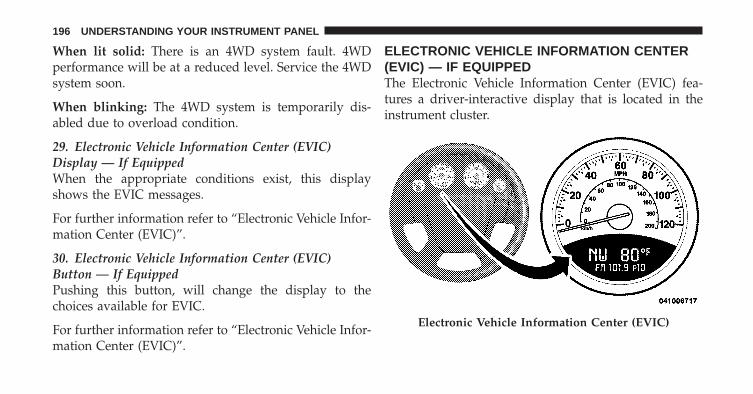
When lit solid: There is an 4WD system fault. 4WDperformance will be at a reduced level. Service the 4WDsystem soon.
When blinking: The 4WD system is temporarily dis-abled due to overload condition.
29. Electronic Vehicle Information Center (EVIC)Display — If EquippedWhen the appropriate conditions exist, this displayshows the EVIC messages.
For further information refer to “Electronic Vehicle Infor-mation Center (EVIC)”.
30. Electronic Vehicle Information Center (EVIC)Button — If EquippedPushing this button, will change the display to thechoices available for EVIC.
For further information refer to “Electronic Vehicle Infor-mation Center (EVIC)”.
ELECTRONIC VEHICLE INFORMATION CENTER(EVIC) — IF EQUIPPEDThe Electronic Vehicle Information Center (EVIC) fea-tures a driver-interactive display that is located in theinstrument cluster.
Electronic Vehicle Information Center (EVIC)
196 UNDERSTANDING YOUR INSTRUMENT PANEL

The EVIC consists of the following:
• System status
• Vehicle information warning message displays
• Personal Settings (Customer-Programmable Features)
• Compass heading
• Outside temperature display
• Trip computer functions
• Uconnect™ Phone displays (if equipped)
• Audio mode display
• Tire Pressure Monitor (TPM)
When the appropriate conditions exist, the EVIC displaysthe following messages:
• Turn Signal On (with a continuous warning chimeafter 1 mile (1.6 km) of distance travelled)
• Left Front Turn Signal Light Out (with a single chime)
• Left Rear Turn Signal Light Out (with a single chime)
• Right Front Turn Signal Light Out (with a singlechime)
• Right Rear Turn Signal Light Out (with a single chime)
• RKE Battery Low (with a single chime)
• Personal Settings Not Available – Vehicle not in PARK(automatic transmission) or vehicle is in motion(manual transmission).
• Left/Right Front Door Ajar (one or more, with a singlechime if speed is above 1 mph/1 km/h)
• Left/Right Rear Door Ajar (one or more, with a singlechime if speed is above 1 mph/1 km/h)
• Door(s) Ajar (with a single chime if vehicle is inmotion)
4
UNDERSTANDING YOUR INSTRUMENT PANEL 197

• Gate Ajar (with a single chime)
• Headlamps or Park Lamps On
• Key In Ignition
• Check TPM System
Engine Oil Change Indicator System —If Equipped
Oil Change RequiredYour vehicle is equipped with an engine oil changeindicator system. The “Oil Change Required” messagewill flash in the EVIC display for approximately fiveseconds after a single chime has sounded, to indicate thenext scheduled oil change interval. The engine oil changeindicator system is duty-cycle based, which means theengine oil change interval may fluctuate dependent uponyour personal driving style.
Unless reset, this message will continue to display eachtime you turn the ignition switch to the ON/RUNposition. To turn off the message temporarily, press andrelease the Trip Odometer button on the instrumentcluster. To reset the oil change indicator system (afterperforming the scheduled maintenance) refer to the fol-lowing procedure.
1. Turn the ignition switch to the ON position. Do notstart the engine.
2. Fully depress the accelerator pedal, slowly, three timeswithin 10 seconds.
3. Turn the ignition switch to the OFF/LOCK position.
NOTE: If the indicator message illuminates when youstart the vehicle, the oil change indicator system did notreset. If necessary repeat this procedure.
198 UNDERSTANDING YOUR INSTRUMENT PANEL
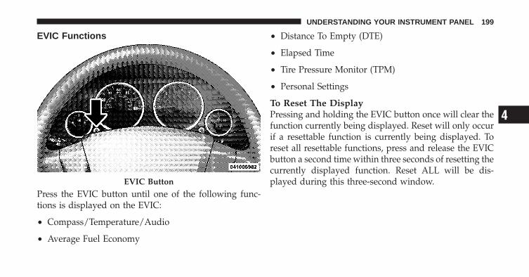
EVIC Functions
Press the EVIC button until one of the following func-tions is displayed on the EVIC:
• Compass/Temperature/Audio
• Average Fuel Economy
• Distance To Empty (DTE)
• Elapsed Time
• Tire Pressure Monitor (TPM)
• Personal Settings
To Reset The DisplayPressing and holding the EVIC button once will clear thefunction currently being displayed. Reset will only occurif a resettable function is currently being displayed. Toreset all resettable functions, press and release the EVICbutton a second time within three seconds of resetting thecurrently displayed function. Reset ALL will be dis-played during this three-second window.EVIC Button
4
UNDERSTANDING YOUR INSTRUMENT PANEL 199

Compass/Temperature/Audio
Press and release the EVIC button to display one of eightcompass headings to indicate the direction the vehicle isfacing, the outside temperature, and the current radiostation.
For additional information regarding the compass, referto Personal Settings (Customer-Programmable Features).
Average Fuel EconomyShows the average fuel economy since the last reset.When the fuel economy is reset, the display will read“RESET” or show dashes for two seconds. Then, thehistory information will be erased, and the averaging willcontinue from the last fuel reading before the reset.
Distance To Empty (DTE)Shows the estimated distance that can be traveled withthe fuel remaining in the tank. This estimated distance is
determined by a weighted average of the instantaneousand average fuel economy, according to the current fueltank level. This is not resettable.
NOTE: Significant changes in driving style or vehicleloading will greatly affect the actual drivable distance ofthe vehicle, regardless of the DTE displayed value.
When the DTE value is less than 30 miles (48 km)estimated driving distance, the DTE display will changeto a text display of �LOW FUEL�. This display willcontinue until the vehicle runs out of fuel. Adding asignificant amount of fuel to the vehicle will turn off the�LOW FUEL� text and a new DTE value will be dis-played, based on the current values in the DTE calcula-tion and the current fuel tank level.
Tire Pressure Monitor (TPM)Refer to “Starting And Operating”, “Tire Pressure Moni-toring System (TPMS)” for system operation.
200 UNDERSTANDING YOUR INSTRUMENT PANEL

Elapsed TimeShows the total elapsed time of travel since the last resetwhen the ignition switch is in the ACC position. Elapsedtime will increment when the ignition switch is in the ONor START position.
Personal Settings(Customer-Programmable Features)This allows the driver to set and recall features when thetransmission is in PARK (automatic transmission) or thevehicle is stopped (manual transmission).
Press and release the EVIC button until “Personal Set-tings” is displayed in the EVIC.
Use the EVIC button to display one of the followingchoices:
LanguageWhen in this display you may select different languagesfor all display nomenclature, including the trip functions.
Pressing the EVIC button while in this display selectsEnglish, Espanol, Deutsch, Italiano, Francais or NL de-pending on availability. As you continue, the displayedinformation will be shown in the selected language.
NOTE: Uconnect™ language will not change using theEVIC. Please refer to “Language Selection” in Uconnect™Phone — If Equipped for details.
Auto Lock Doors at 15 mph (24 km/h)When ON is selected, all doors lock automatically whenthe speed of the vehicle reaches 15 mph (24 km/h). Pressand hold the EVIC button when in this display until“ON” or “OFF” appears to make your selection.
Auto Unlock On ExitWhen ON is selected, all the vehicle’s doors will unlockwhen the driver’s door is opened, if the vehicle isstopped (manual transmission) or the vehicle is stoppedand the transmission is in the PARK or NEUTRAL
4
UNDERSTANDING YOUR INSTRUMENT PANEL 201
position (automatic transmission). Press and hold theEVIC button when in this display until “ON” or “OFF”appears to make your selection.
RKE Unlock Driver’s Door 1stWhen Driver’s Door 1st is selected only the driver’s doorwill unlock on the first press of the Remote Keyless Entry(RKE) transmitter UNLOCK button and require a secondpress to unlock the remaining locked doors. When Re-mote Unlock All Doors is selected, all of the doors willunlock at the first press of the RKE transmitter UNLOCKbutton. Press and hold the EVIC button when in thisdisplay until “Driver’s Door 1st” or “All Doors” appearsto make your selection.
Flash Lamps with LockWhen ON is selected, the front and rear turn signals willflash when the doors are locked or unlocked using theRKE transmitter. This feature may be selected with orwithout the sound horn on lock feature selected. Press
and hold the EVIC button when in this display until“ON” or “OFF” appears to make your selection.
Sound Horn with LockWhen ON is selected, a short horn sound will occur whenthe RKE transmitter LOCK button is pressed. This featuremay be selected with or without the Flash Lights withLock feature. Press and hold the EVIC button when inthis display until “ON” or “OFF” appears to make yourselection.
Headlamp Off DelayWhen this feature is selected the driver can choose tohave the headlights remain on for 0, 30, 60, or 90 secondswhen exiting the vehicle. Press and hold the EVIC buttonwhen in this display until 0, 30, 60, or 90 appears to makeyour selection.
Key Off Power DelayWhen this feature is selected the power windowswitches, radio, Uconnect™ Phone, power sunroof, and
202 UNDERSTANDING YOUR INSTRUMENT PANEL
power outlets will remain active for up to 10 minutesafter the ignition switch has been turned OFF. Opening avehicle door will cancel this feature. Press and hold theEVIC button when in this display until “OFF”, “45 sec.”,“5 min.”, or “10 min.” appears to make your selection.
Illuminated ApproachWhen this feature is selected the headlights will activateand remain on for up to 90 seconds when the doors areunlocked using the RKE transmitter. Press and hold theEVIC button when in this display until “OFF”, “30 sec.”,“60 sec.”, or “90 sec.” appears to make your selection.
Hill Start Assist (HSA) — If EquippedWhen on is selected, the HSA system is active. Refer to“Electronic Brake Control System” in “Starting AndOperating” for system function and operating informa-tion. To make your selection, press and release the EVICbutton until “On” or “Off” appears.
Display Units InThe EVIC, odometer, and Uconnect™ gps system unitscan be changed between English and Metric.
Press and hold the EVIC button when in this display until“ENGLISH” or “METRIC” appears to make yourselection.
Confirmation of Voice Commands — If EquippedWhen ON is selected, all voice commands from theUconnect™ system are confirmed. Press and hold theEVIC button when in this display until “ON” or “OFF”appears to make your selection.
Automatic Compass CalibrationWhen the vehicle is new, the compass may appear erraticand the EVIC will display “CAL” until the compass iscalibrated. You may also calibrate the compass by com-pleting one or more 360 degree turns (in an area free from
4
UNDERSTANDING YOUR INSTRUMENT PANEL 203

large metal or metallic objects) until the “CAL” messagedisplayed in the EVIC turns off. The compass will nowfunction normally.
NOTE: A good calibration requires a level surface andan environment free from large metallic objects such asbuildings, bridges, underground cables, railroad tracks,etc.
Compass VarianceCompass Variance is the difference between MagneticNorth and Geographic North. To ensure compass accu-racy, the compass variance should be properly set accord-ing to the variance map for the zone where the vehiclewill be driven. When properly set, the compass willautomatically account for this difference.
NOTE: Magnetic and battery powered devices, (such ascell phones, iPod’s, radar detectors, PDA’s and laptops)should be kept away from the top of the instrument
panel. This is where the compass module is located andsuch devices may interfere and cause false compassreadings.
To Set the Variance With the ignition in the ON position,quickly (less than one second) press and release the EVIC
Compass Variance Map
204 UNDERSTANDING YOUR INSTRUMENT PANEL
button several times until you have displayed the Per-sonal Settings (Customer-Programmable Features) menu.Once in the Personal Settings (Customer-ProgrammableFeatures) menu, press and release (less than one second)the EVIC button several times until “Compass Variance”is displayed. The “Compass Variance” message and thecurrent variance zone number will be displayed. Tochange the zone, press and hold (longer than two sec-onds) the EVIC button to increment the variance onestep. Repeat as necessary, with individual long (for atleast 1 second) EVIC button presses for each increment,until the desired variance is achieved. To exit the Vari-ance Programming, press the EVIC button with a short(less than one second) button press.
NOTE: The factory default is Zone 8. During program-ming, the zone value will wrap around from Zone 15 toZone 1.
Compass CalibrationIf the compass appears erratic or inaccurate, and thevariance has been properly set, you may wish to manu-ally recalibrate the compass. To manually calibrate thecompass:
1. Start the engine and leave the transmission in thePARK position.
2. Press and release the EVIC button (less than onesecond) several times until the EVIC displays the “Per-sonal Settings (Customer-Programmable Features)”menu.
3. Once in the “Personal Settings (Customer-Program-mable Features)” menu, press and release the EVICbutton (less than one second) several times until “Cali-brate Compass (Yes)” is displayed.
4. Press the EVIC button (more than one second), thiswill place the Compass in calibration mode. The CAL
4
UNDERSTANDING YOUR INSTRUMENT PANEL 205

indicator will come on continuously in the EVIC displayto indicate that the compass is now in the calibrationmode, and that the vehicle can now be driven to calibrate.
5. To complete the compass calibration, drive the vehiclein one or more complete 360–degree circle under 5 mph(8 km/h) in an area free from power lines and largemetallic objects, until the “CAL” indicator turns off. Thecompass will now function normally.
NOTE: Press the EVIC button (less than one second)from the �Calibrate Compass (Yes)� screen will exit theEVIC Customer-Programmable Features, and return it toits normal operating mode.
MEDIA CENTER 230 (REQ) — AM/FM STEREORADIO AND 6–DISC CD/DVD CHANGER(MP3/WMA AUX JACK)
NOTE: The radio sales code is located on the lower rightside of the radio faceplate.
Operating Instructions - Radio Mode
NOTE: The ignition switch must be in the ON or ACCposition to operate the radio.
REQ Radio
206 UNDERSTANDING YOUR INSTRUMENT PANEL

Power Switch/Volume Control (Rotary)Push the ON/VOLUME control knob to turn on theradio. Press the ON/VOLUME control knob a secondtime to turn off the radio.
Electronic Volume ControlThe electronic volume control turns continuously (360degrees) in either direction without stopping. Turning theON/VOLUME control knob to the right increases thevolume and to the left decreases it.
When the audio system is turned ON, the sound will beset at the same volume level as last played.
SEEK ButtonsPress and release the SEEK buttons to search for the nextlistenable station in AM/FM mode. Press the right switchto seek up and the left switch to seek down. The radiowill remain tuned to the new station until you makeanother selection. Holding either button will bypassstations without stopping until you release it.
SCAN ButtonPressing the SCAN button causes the tuner to search forthe next listenable station in AM, FM or Satellite (ifequipped) frequencies, pausing for five seconds at eachlistenable station before continuing to the next. To stopthe search, press the SCAN button a second time.
Voice Command Button Uconnect™ Phone — IfEquippedPress this button to operate the Uconnect™ Phone feature(if equipped). Refer to “Uconnect™ Phone” in “Under-standing The Features Of Your Vehicle”.
If your vehicle is not equipped with or this feature is notavailable on your vehicle, a “Not Equipped WithUconnect” message will display on the radio screen.
Phone Button Uconnect™ Phone — If EquippedPress this button to operate the Uconnect™ Phone feature(if equipped). Refer to “Uconnect™ Phone” in “Under-standing The Features Of Your Vehicle”.
4
UNDERSTANDING YOUR INSTRUMENT PANEL 207

If your vehicle is not equipped with or this feature is notavailable on your vehicle, a “Not Equipped WithUconnect” message will display on the radio screen.
TIME ButtonPress the TIME button to alternate locations of the timeand frequency display.
Clock Setting Procedure
1. Press and hold the TIME button until the hours blink.
2. Adjust the hours by turning the right side TUNE/SCROLL control knob.
3. After adjusting the hours, press the right side TUNE/SCROLL control knob to set the minutes. The minuteswill begin to blink.
4. Adjust the minutes using the right side TUNE/SCROLL control knob. Press the TUNE/SCROLL controlknob to save the time change.
5. To exit, press any button/knob or wait five seconds.
The clock can also be set by pressing the SETUP buttonand selecting the “SET HOME CLOCK” entry. Once inthis display follow the above procedure, starting atstep 2.
INFO ButtonPress the INFO button for an RDS station (one with callletters displayed). The radio will return a Radio Textmessage broadcast from an FM station (FM mode only).
RW/FFPressing the RW (Rewind) or FF (Fast Forward) buttonscauses the tuner to search for the next frequency in thedirection of the arrows. This feature operates in AM, FMor Satellite (if equipped) frequencies.
TUNE ControlTurn the rotary TUNE/SCROLL control knob clockwiseto increase or counterclockwise to decrease the frequency.
208 UNDERSTANDING YOUR INSTRUMENT PANEL
Setting the Tone, Balance, and FadePush the rotary TUNE/SCROLL control knob and BASSwill display. Turn the TUNE/SCROLL control knob tothe right or left to increase or decrease the bass tones.
Push the rotary TUNE/SCROLL control knob a secondtime and MID will display. Turn the TUNE/SCROLLcontrol knob to the right or left to increase or decrease themid-range tones.
Push the rotary TUNE/SCROLL control knob a thirdtime and TREBLE will display. Turn the TUNE/SCROLLcontrol knob to the right or left to increase or decrease thetreble tones.
Push the rotary TUNE/SCROLL control knob a fourthtime and BALANCE will display. Turn the TUNE/SCROLL control knob to the right or left to adjust thesound level from the right or left side speakers.
Push the rotary TUNE/SCROLL control knob a fifth timeand FADE will display. Turn the TUNE/SCROLL controlknob to the left or right to adjust the sound level betweenthe front and rear speakers.
Push the rotary TUNE/SCROLL control knob again toexit setting tone, balance, and fade.
MUSIC TYPE ButtonPressing this button once will turn on the Music Typemode for five seconds. Pressing the MUSIC TYPE buttonor turning the TUNE/SCROLL control knob within fiveseconds will allow the program format type to be se-lected. Many radio stations do not currently broadcastMusic Type information.
4
UNDERSTANDING YOUR INSTRUMENT PANEL 209
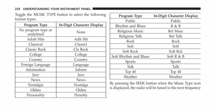
Toggle the MUSIC TYPE button to select the followingformat types:
Program Type 16-Digit Character DisplayNo program type or
undefined None
Adult Hits Adlt HitClassical Classicl
Classic Rock Cls RockCollege CollegeCountry Country
Foreign Language LanguageInformation Inform
Jazz JazzNews News
Nostalgia NostalgaOldies Oldies
Personality Persnlty
Program Type 16-Digit Character DisplayPublic Public
Rhythm and Blues R & BReligious Music Rel MuscReligious Talk Rel Talk
Rock RockSoft Soft
Soft Rock Soft RckSoft Rhythm and Blues Soft R & B
Sports SportsTalk Talk
Top 40 Top 40Weather Weather
By pressing the SEEK button when the Music Type iconis displayed, the radio will be tuned to the next frequency
210 UNDERSTANDING YOUR INSTRUMENT PANEL

station with the same selected Music Type name. TheMusic Type function only operates when in the FMmode.
If a preset button is activated while in the Music Type(Program Type) mode, the Music Type mode will beexited and the radio will tune to the preset station.
SETUP ButtonPressing the SETUP button allows you to select betweenthe following items:
NOTE: Turn the TUNE/SCROLL control knob to scrollthrough the entries. Push the AUDIO/SELECT button toselect an entry and make changes.
• DVD Enter - When the disc is in DVD Menu mode,selecting DVD Enter will allow you to play the currenthighlighted selection. Use the remote control to scrollup and down the menu (if equipped).
• DISC Play/Pause - You can toggle betweenplaying the DVD and pausing the DVD bypushing the SELECT button (if equipped).
• DVD Play Options - Selecting the DVD Play Optionswill display the following:
• Subtitle – Repeatedly pressing SELECT will switchsubtitles to different subtitle languages that areavailable on the disc (if equipped).
• Audio Stream – Repeatedly pressing SELECT willswitch to different audio languages (if supported onthe disc) (if equipped).
• Angle – Repeatedly pressing SELECT will changethe viewing angle if supported by the DVD disc (ifequipped).
4
UNDERSTANDING YOUR INSTRUMENT PANEL 211

NOTE:• The available selections for each of the above entries
varies depending upon the disc.
• These selections can only be made while playing aDVD.
• VES™ Power - Allows you to turn VES™ ON andOFF (if equipped).
• VES™ Lock - Locks out rear VES™ remote controls (ifequipped).
• VES™ CH1/CH2 - Allows the user to change themode of either the IR1 or IR2 wireless headphones bypressing the AUDIO/SELECT button (if equipped).
• Set Home Clock - Pressing the SELECT button allowsyou to set the clock. Turn the TUNE/SCROLL controlknob to adjust the hours and then press and turn the
TUNE/SCROLL control knob to adjust the minutes.Press the TUNE/SCROLL control knob again to savechanges.
• Player Defaults - Selecting this item will allow theuser to scroll through the following items and setdefaults according to customer preference.
Menu Language — If EquippedSelecting this item will allow the user to choose thedefault startup DVD menu language (effective only iflanguage supported by disc). If you want to select alanguage not listed, then scroll down and select �other.�Enter the four-digit country code using the TUNE/SCROLL control knob to scroll up and down to select thenumber and then push to select.
Audio Language — If EquippedSelecting this item allows you to choose a default audiolanguage (effective only if the language is supported bythe disc). You can select a language not listed by scrolling
212 UNDERSTANDING YOUR INSTRUMENT PANEL
down and selecting �other.� Enter the country code usingthe TUNE/SCROLL control knob to scroll up and downto select the number and then push to select.
Subtitle Language — If EquippedSelecting this item allows you to choose a default subtitlelanguage (effective only if the language is supported bythe disc). You can select a language not listed by scrollingdown and selecting �other.� Enter the country code usingthe TUNE/SCROLL control knob to scroll up and downto select the number and then push to select.
Subtitles — If EquippedSelecting this item allows you to choose between subtitleOff or On.
Audio DRC — If EquippedSelecting this item allows you to limit maximum audiodynamic range. The default is set to �High,� and underthis setting, dialogues will play at 11 db higher than if thesetting is �Normal.�
Aspect Ratio — If EquippedSelecting this item allows you to choose between widescreen, pan scan, and letter box.
AutoPlay — If EquippedWhen this is set to On and a DVD video is inserted, it willbypass the DVD menu screen and automatically play themovie. In some rare cases, the DVD player may notauto-play the main title. In such cases, use the MENUbutton on the remote control to select desired title to play.
NOTE: The user will have to set these defaults beforeloading a disc. If changes are made to these settings aftera disc is loaded, changes will not be effective. Also, thedefaults are effective only if the disc supports thecustomer-preferred settings.
AM and FM ButtonsPress the buttons to select AM or FM mode.
4
UNDERSTANDING YOUR INSTRUMENT PANEL 213

SET Button — To Set the Pushbutton MemoryWhen you are receiving a station that you wish tocommit to pushbutton memory, press the SET button.The symbol SET 1 will now show in the display window.Select the button (1-6) you wish to lock onto this stationand press and release that button. If a button is notselected within five seconds after pressing the SET but-ton, the station will continue to play but will not bestored into pushbutton memory.
You may add a second station to each pushbutton byrepeating the above procedure with this exception: Pressthe SET button twice and SET 2 will show in the displaywindow. Each button can be set for SET 1 and SET 2 inboth AM and FM. This allows a total of 12 AM, 12 FM,and 12 Satellite (if equipped) stations to be stored intopushbutton memory. The stations stored in SET 2memory can be selected by pressing the pushbuttontwice.
Every time a preset button is used, a correspondingbutton number will display.
Buttons 1 - 6These buttons tune the radio to the stations that youcommit to pushbutton memory {12 AM, 12 FM, and 12Satellite (if equipped) stations}.
DISC ButtonPressing the DISC button will allow you to switch fromAM/FM modes to Disc modes.
Operation Instructions - (DISC MODE for CD andMP3/WMA Audio Play, DVD-VIDEO)The radio DVD player and many DVD discs are coded bygeographic region. These region codes must match inorder for the disc to play. If the region code for the DVDdisc does not match the region code for the radio DVDplayer, it will not play the disc. Customers may take theirvehicle to an authorized dealer to change the region codeof the player a maximum of five times.
214 UNDERSTANDING YOUR INSTRUMENT PANEL

CAUTION!
The radio may shut down during extremely hotconditions. When this occurs, the radio will indicate“Disc Hot” and shut off until a safe temperature isreached. This shutdown is necessary to protect theoptics of the DVD player and other radio internalcomponents.
NOTE: The ignition switch must be in the ON or ACCposition to operate the radio.
LOAD Button — Loading Compact Disc(s)Press the LOAD button and the pushbutton with thecorresponding number (1-6) where the CD is beingloaded. The radio will display PLEASE WAIT andprompt when to INSERT DISC. After the radio displays�INSERT DISC,� insert the CD into the player.
Radio display will show �LOADING DISC� when the discis loading and “READING DISC” when the radio isreading the disc.
CAUTION!
This CD player will accept 4–3/4 in (12 cm) discs only.The use of other sized discs may damage the CDplayer mechanism.
Eject Button — Ejecting Compact Disc(s)Press the EJECT button and the pushbuttonwith the corresponding number (1-6) where theCD was loaded and the disc will unload andmove to the entrance for easy removal. Radio
display will show �EJECTING DISC� when the disc isbeing ejected and prompt the user to remove the disc.
Press and hold the EJECT button for five seconds and allCDs will be ejected from the radio.
4
UNDERSTANDING YOUR INSTRUMENT PANEL 215

The disc can be ejected with the radio and ignition OFF.
SEEK Button (CD MODE)Press the right SEEK button for the next selection on theCD. Press the left SEEK button to return to the beginningof the current selection, or return to the beginning of theprevious selection if the CD is within the first second ofthe current selection. Pressing and holding the SEEKbutton will allow you to scroll through the tracks faster inCD and MP3/MWA modes.
SCAN Button (CD MODE)Press the SCAN button to scan through each track on theCD currently playing.
TIME Button (CD MODE)Press this button to change the display from a large CDplaying time display to a small CD playing time display.
RW/FF (CD MODE)Press and hold FF (Fast Forward) and the CD player willbegin to fast forward until FF is released, or RW oranother CD button is pressed. The RW (Rewind) buttonworks in a similar manner.
AM or FM Button (CD MODE)Switches the radio into the AM or FM radio mode.
Notes On Playing MP3/WMA FilesThe radio can play MP3/WMA files; however, acceptableMP3/WMA file recording media and formats are limited.When writing MP3/WMA files, pay attention to thefollowing restrictions.
Supported Media (Disc Types)The MP3/WMA file recording media supported by theradio are CDDA, CD-R, CD-RW, MP3,WMA, DVD Video,DVD-R, DVD-RW, DVD+R, DVD+RW, and CDDA+MP3.
216 UNDERSTANDING YOUR INSTRUMENT PANEL
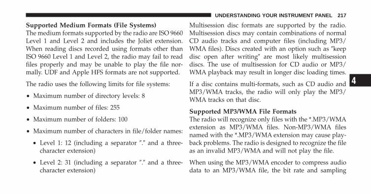
Supported Medium Formats (File Systems)The medium formats supported by the radio are ISO 9660Level 1 and Level 2 and includes the Joliet extension.When reading discs recorded using formats other thanISO 9660 Level 1 and Level 2, the radio may fail to readfiles properly and may be unable to play the file nor-mally. UDF and Apple HFS formats are not supported.
The radio uses the following limits for file systems:
• Maximum number of directory levels: 8
• Maximum number of files: 255
• Maximum number of folders: 100
• Maximum number of characters in file/folder names:
• Level 1: 12 (including a separator �.� and a three-character extension)
• Level 2: 31 (including a separator �.� and a three-character extension)
Multisession disc formats are supported by the radio.Multisession discs may contain combinations of normalCD audio tracks and computer files (including MP3/WMA files). Discs created with an option such as �keepdisc open after writing� are most likely multisessiondiscs. The use of multisession for CD audio or MP3/WMA playback may result in longer disc loading times.
If a disc contains multi-formats, such as CD audio andMP3/WMA tracks, the radio will only play the MP3/WMA tracks on that disc.
Supported MP3/WMA File FormatsThe radio will recognize only files with the *.MP3/WMAextension as MP3/WMA files. Non-MP3/WMA filesnamed with the *.MP3/WMA extension may cause play-back problems. The radio is designed to recognize the fileas an invalid MP3/WMA and will not play the file.
When using the MP3/WMA encoder to compress audiodata to an MP3/WMA file, the bit rate and sampling
4
UNDERSTANDING YOUR INSTRUMENT PANEL 217
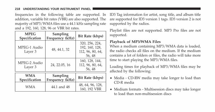
frequencies in the following table are supported. Inaddition, variable bit rates (VBR) are also supported. Themajority of MP3/WMA files use a 44.1 kHz sampling rateand a 192, 160, 128, 96 or VBR bit rates.
MPEGSpecification
SamplingFrequency (kHz) Bit Rate (kbps)
MPEG-1 AudioLayer 3 48, 44.1, 32
320, 256, 224,192, 160, 128,
112, 96, 80, 64,56, 48
MPEG-2 AudioLayer 3 24, 22.05, 16
160, 128, 144,112, 96, 80, 64,
56, 48
WMASpecification
SamplingFrequency (kHz) Bit Rate (kbps)
WMA 44.1 and 48 48, 64, 96, 128,160, 192 VBR
ID3 Tag information for artist, song title, and album titleare supported for ID3 version 1 tags. ID3 version 2 is notsupported by the radios.
Playlist files are not supported. MP3 Pro files are notsupported.
Playback of MP3/WMA FilesWhen a medium containing MP3/WMA data is loaded,the radio checks all files on the medium. If the mediumcontains a lot of folders or files, the radio will take moretime to start playing the MP3/WMA files.
Loading times for playback of MP3/WMA files may beaffected by the following:
• Media - CD-RW media may take longer to load thanCD-R media
• Medium formats - Multisession discs may take longerto load than non-multisession discs
218 UNDERSTANDING YOUR INSTRUMENT PANEL

• Number of files and folders - Loading times willincrease with more files and folders
To increase the speed of disc loading, it is recommendedto use CD-R media and single-session discs. To create asingle-session disc, enable the “Disc at Once” optionbefore writing to the disc.
LIST Button (DISC Mode for MP3/WMA Play)Pressing the LIST button will bring up a list of all folderson the disc. Scrolling up or down the list is done byturning the TUNE/SCROLL control knob. Selecting afolder by pressing the TUNE/SCROLL control knob willbegin playing the files contained in that folder (or thenext folder in sequence if the selection does not containplayable files).
The folder list will time out after five seconds.
INFO Button (DISC Mode for MP3/WMA Play)Pressing the INFO button repeatedly will scroll throughthe following TAG information: Song Title, Artist, FileName, and Folder Name (if available).
Press the INFO button once more to return to �elapsedtime� priority mode.
Press and hold the INFO button for three seconds ormore and radio will display song titles for each file.
Press and hold the INFO button again for three secondsto return to �elapsed time� display.
Operation Instructions - Auxiliary ModeThe auxiliary (AUX) jack is an audio input jack whichallows the user to plug in a portable device such as anMP3/WMA player, cassette player, or microphone andutilize the vehicle’s audio system to amplify the sourceand play through the vehicle speakers.
4
UNDERSTANDING YOUR INSTRUMENT PANEL 219
Pressing the AUX button will change the mode to auxil-iary device if the AUX jack is connected.
NOTE: The AUX device must be turned on and thedevice’s volume set to the proper level. If the AUX audiois not loud enough, turn the device’s volume up. If theAUX audio sounds distorted, turn the device’s volumedown.
SEEK Button (Auxiliary Mode)No function.
SCAN Button (Auxiliary Mode)No function.
EJECT Button (Auxiliary Mode)No function.
TIME Button (Auxiliary Mode)Press the TIME button to change the display fromelapsed playing time to time of day. The time of day willdisplay for five seconds.
RW/FF (Auxiliary Mode)No function.
SET Button (Auxiliary Mode)No function.
Operating Instructions — Voice Command System(If Equipped)For the radio, refer to “Voice Command” in “Understand-ing The Features Of Your Vehicle”.
For Uconnect™ “Voice Command,” refer to “Uconnect™Phone” in “Understanding The Features Of YourVehicle”.
220 UNDERSTANDING YOUR INSTRUMENT PANEL

Operating Instructions - Uconnect™ Phone(If Equipped)Refer to “Uconnect™ Phone” in “Understanding TheFeatures Of Your Vehicle”.
Operating Instructions - Uconnect™ Multimedia(Satellite Radio) (If Equipped)Refer to “Uconnect™ Multimedia (Satellite Radio)”.
Operating Instructions - Video EntertainmentSystem (VES)™ (If Equipped)Refer to separate “Video Entertainment System (VES)™Guide.”
Dolby�Manufactured under license from Dolby� Laboratories.�Dolby�� and the double-D symbol are trademarks ofDolby� Laboratories.
MacrovisionThis product incorporates copyright protection technol-ogy that is protected by U.S. patents and other intellec-tual property rights. Use of this copyright protectiontechnology must be authorized by Macrovision, and isintended for home and other limited viewing uses only,unless otherwise authorized by Macrovision. Reverseengineering or disassembly is prohibited.
DTS™�DTS™� and �DTS™ 2.0� are trademarks of Digital The-ater Systems, Inc.
MEDIA CENTER 730N/430 (RER/REN/RBZ) —AM/FM STEREO RADIO AND CD/DVD/HDD/NAV —IF EQUIPPED
NOTE: The sales code is located on the lower right sideof the unit’s faceplate.
4
UNDERSTANDING YOUR INSTRUMENT PANEL 221

The REN, RER and RBZ radios contain a CD/DVDplayer, USB port, and a 30-gigabyte hard drive (HDD).Sirius Satellite Radio is optional. The 6.5 in (16.5 cm)touch screen allows for easy menu selection.
The RER radio also contains a Global Positioning System(GPS)-based Navigation system.
Refer to your Uconnect™ Multimedia REN, RER or RBZuser’s manual for detailed operating instructions.
Operating Instructions — Voice CommandSystem — If EquippedFor the radio, refer to “Voice Command” in “Understand-ing The Features Of Your Vehicle”.
Operating Instructions — Uconnect™ Phone —If EquippedRefer to “Uconnect™ Phone” in “Understanding TheFeatures Of Your Vehicle”.
Clock Setting Procedure — RBZ Radio
To Manually Set the Clock
1. Turn on the radio.
2. Touch the screen where the time is displayed, the clocksetting menu will appear on the screen.
3. To move the hour forward, touch the screen where theword “Hour” with the arrow pointing upward is dis-played. To move the hour backward, touch the screenwhere the word “Hour” with the arrow pointing down-ward is displayed.
4. To move the minute forward, touch the screen wherethe word “Min” with the arrow pointing upward isdisplayed. To move the minute backward, touch thescreen where the word “Min” with the arrow pointingdownward is displayed.
222 UNDERSTANDING YOUR INSTRUMENT PANEL

5. To save the new time setting, touch the screen wherethe word “Save” is displayed.
Changing Daylight Savings TimeWhen selected, this feature will display the time of day indaylight savings time. Proceed as follows to change thecurrent setting:
1. Turn on the radio.
2. Touch the screen where the time is displayed. Theclock setting menu will appear on the screen.
3. When this feature is on, a check mark will appear inthe box next to the words “Daylight Savings.” Touch thescreen where the words “Daylight Savings” are dis-played to change the current setting.
Show Time if Radio is OffWhen selected, this feature will display the time of dayon the touch screen when the radio is turned off. Proceedas follows to change the current setting:
1. Turn on the radio.
2. Touch the screen where the time is displayed. Theclock setting menu will appear on the screen.
3. When this feature is on, a check mark will appear inthe box next to the words “Show Time if Radio is Off.”Touch the screen where the words “Show Time if Radio isOff” are displayed to change the current setting.
Changing the Time Zone
1. Turn on the radio.
2. Touch the screen where the time is displayed. Theclock setting menu will appear on the screen.
4
UNDERSTANDING YOUR INSTRUMENT PANEL 223

3. Touch the screen where the words “Set Time Zone” aredisplayed. The time zone selection menu will appear onthe screen.
4. Select a time zone by touching the screen where yourselection appears. If you do not see a time zone that youwant to select, touch the screen where the word “Page” isdisplayed to view additional time zones in the menu.
5. Touch the screen where the word “Save” is displayed.
Clock Setting Procedure — RER/REN Radio
Uconnect� gps — RER OnlyThe GPS receiver used in this system is synchronized tothe time data being transmitted by the GPS satellite. Thesatellite clock is Greenwich Mean Time (GMT). This is theworldwide standard for time. This makes the system’sclock very accurate once the appropriate time zone anddaylight savings information is set.
To Manually Set the Clock — RER/REN
1. Turn on the radio.
2. Touch the screen where the time is displayed.
3. Touch the screen where “User Clock” is displayed, theclock setting menu will appear on the screen.
4. To move the hour forward, touch the screen where theword “Hour” with the arrow pointing upward is dis-played. To move the hour backward, touch the screenwhere the word “Hour” with the arrow pointing down-ward is displayed.
5. To move the minute forward, touch the screen wherethe word “Min” with the arrow pointing upward isdisplayed. To move the minute backward, touch thescreen where the word “Min” with the arrow pointingdownward is displayed.
224 UNDERSTANDING YOUR INSTRUMENT PANEL
6. To save the new time setting, touch the screen wherethe word “Save” is displayed.
Changing Daylight Savings TimeWhen selected, this feature will display the time of day indaylight savings time. Proceed as follows to change thecurrent setting:
1. Turn on the radio.
2. Touch the screen where “User Clock” is displayed, theclock setting menu will appear on the screen.
3. When this feature is on, a check mark will appear inthe box next to the words “Daylight Savings.” Touch thescreen where the words “Daylight Savings” are dis-played to change the current setting.
Show Time if Radio is OffWhen selected, this feature will display the time of dayon the touch screen when the radio is turned off. Proceedas follows to change the current setting:
1. Turn on the radio.
2. Touch the screen where the time is displayed.
3. Touch the screen where “User Clock” is displayed, theclock setting menu will appear on the screen.
4. When this feature is on, a check mark will appear inthe box next to the words “Show Time if Radio is Off.”Touch the screen where the words “Show Time if Radio isOff” are displayed to change the current setting.
Changing the Time Zone
1. Turn on the radio.
2. Touch the screen where the time is displayed.
4
UNDERSTANDING YOUR INSTRUMENT PANEL 225
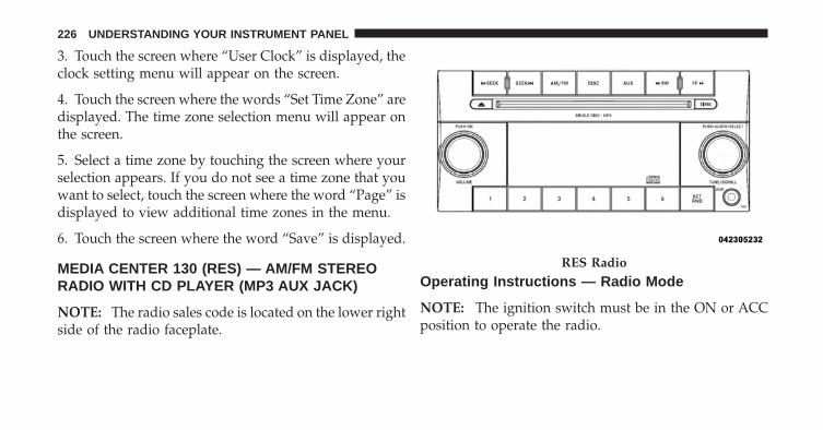
3. Touch the screen where “User Clock” is displayed, theclock setting menu will appear on the screen.
4. Touch the screen where the words “Set Time Zone” aredisplayed. The time zone selection menu will appear onthe screen.
5. Select a time zone by touching the screen where yourselection appears. If you do not see a time zone that youwant to select, touch the screen where the word “Page” isdisplayed to view additional time zones in the menu.
6. Touch the screen where the word “Save” is displayed.
MEDIA CENTER 130 (RES) — AM/FM STEREORADIO WITH CD PLAYER (MP3 AUX JACK)
NOTE: The radio sales code is located on the lower rightside of the radio faceplate.
Operating Instructions — Radio Mode
NOTE: The ignition switch must be in the ON or ACCposition to operate the radio.
RES Radio
226 UNDERSTANDING YOUR INSTRUMENT PANEL

Power Switch/Volume Control (Rotary)Push the ON/VOLUME control knob to turn on theradio. Push the ON/VOLUME control knob a secondtime to turn off the radio.
Electronic Volume ControlThe electronic volume control turns continuously (360degrees) in either direction, without stopping. Turningthe ON/VOLUME control knob to the right increases thevolume, and to the left decreases it.
When the audio system is turned on, the sound will beset at the same volume level as last played.
SEEK ButtonsPress and release the SEEK buttons to search for the nextlistenable station in AM/FM mode. Press the right switchto seek up and the left switch to seek down. The radiowill remain tuned to the new station until you makeanother selection. Holding either button will bypassstations without stopping, until you release it.
TIME ButtonPress the TIME button to alternate display of the timeand radio frequency.
Clock Setting Procedure
1. Press and hold the TIME button until the hours blink.
2. Adjust the hours by turning the right side TUNE/SCROLL control knob.
3. After adjusting the hours, press the right side TUNE/SCROLL control knob to set the minutes. The minuteswill begin to blink.
4. Adjust the minutes using the right side TUNE/SCROLL control knob. Press the TUNE/SCROLL controlknob to save time change.
5. To exit, press any button/knob, or wait five seconds.
4
UNDERSTANDING YOUR INSTRUMENT PANEL 227

RW/FFPressing the RW (Rewind) or FF (Fast Forward) buttonscauses the tuner to search for the next frequency in thedirection of the arrows. This feature operates in eitherAM or FM frequencies.
TUNE ControlTurn the rotary TUNE/SCROLL control knob clockwiseto increase or counterclockwise to decrease the frequency.
Setting the Tone, Balance, and FadePush the rotary TUNE/SCROLL control knob and BASSwill display. Turn the TUNE/SCROLL control knob tothe right or left to increase or decrease the bass tones.
Push the rotary TUNE/SCROLL control knob a secondtime and MID will display. Turn the TUNE/SCROLLcontrol knob to the right or left to increase or decrease themid-range tones.
Push the rotary TUNE/SCROLL control knob a thirdtime and TREBLE will display. Turn the TUNE/SCROLLcontrol knob to the right or left to increase or decrease thetreble tones.
Push the rotary TUNE/SCROLL control knob a fourthtime and BALANCE will display. Turn the TUNE/SCROLL control knob to the right or left to adjust thesound level from the right or left side speakers.
Push the rotary TUNE/SCROLL control knob a fifth timeand FADE will display. Turn the TUNE/SCROLL controlknob to the left or right to adjust the sound level betweenthe front and rear speakers.
Push the rotary TUNE/SCROLL control knob again toexit setting tone, balance, and fade.
AM/FM ButtonPress the buttons to select either AM or FM mode.
228 UNDERSTANDING YOUR INSTRUMENT PANEL

SET/RND Button — To Set the PushbuttonMemoryWhen you are receiving a station that you wish tocommit to pushbutton memory, press the SET/RNDbutton. The symbol SET 1 will now show in the displaywindow. Select the button (1 to 6) you wish to lock ontothis station and press and release that button. If a buttonis not selected within five seconds after pressing theSET/RND button, the station will continue to play butwill not be stored into pushbutton memory.
You may add a second station to each pushbutton byrepeating the above procedure with this exception: Pressthe SET/RND button twice and SET 2 will show in thedisplay window. Each button can be set for SET 1 andSET 2 in both AM and FM. This allows a total of 12 AMand 12 FM stations to be stored into pushbutton memory.The stations stored in SET 2 memory can be selected bypressing the pushbutton twice.
Every time a preset button is used, a correspondingbutton number will display.
Buttons 1 - 6These buttons tune the radio to the stations that youcommit to pushbutton memory (12 AM and 12 FMstations).
DISC ButtonPressing the DISC button will allow you to switch fromAM/FM modes to Disc modes.
Operation Instructions — CD MODE For CD AndMP3 Audio Play
NOTE:• The ignition switch must be in the ON or ACC
position to operate the radio.
4
UNDERSTANDING YOUR INSTRUMENT PANEL 229

• This radio is capable of playing compact discs (CD),recordable compact discs (CD-R), rewritable compactdiscs (CD-RW), compact discs with MP3 tracks andmultisession compact discs with CD and MP3 tracks.
Inserting Compact Disc(s)Gently insert one CD into the CD player with the CDlabel facing up. The CD will automatically be pulled intothe CD player and the CD icon will illuminate on theradio display. If a CD does not go into the slot more than1.0 in (2.5 cm), a disc may already be loaded and must beejected before a new disc can be loaded.
If you insert a disc with the ignition ON and the radioON, the unit will switch from radio to CD mode andbegin to play when you insert the disc. The display willshow the track number, and index time in minutes andseconds. Play will begin at the start of track 1.
CAUTION!
• This CD player will accept 4-3/4 in (12 cm) discsonly. The use of other sized discs may damage theCD player mechanism.
• Do not use adhesive labels. These labels can peelaway and jam the player mechanism.
• RES is a single CD player. Do not attempt to inserta second CD if one is already loaded.
• Dual-media disc types (one side is a DVD, theother side is a CD) should not be used, and theycan cause damage to the player.
EJECT Button - Ejecting a CDPress the EJECT button to eject the CD.
230 UNDERSTANDING YOUR INSTRUMENT PANEL
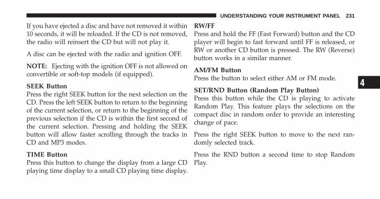
If you have ejected a disc and have not removed it within10 seconds, it will be reloaded. If the CD is not removed,the radio will reinsert the CD but will not play it.
A disc can be ejected with the radio and ignition OFF.
NOTE: Ejecting with the ignition OFF is not allowed onconvertible or soft-top models (if equipped).
SEEK ButtonPress the right SEEK button for the next selection on theCD. Press the left SEEK button to return to the beginningof the current selection, or return to the beginning of theprevious selection if the CD is within the first second ofthe current selection. Pressing and holding the SEEKbutton will allow faster scrolling through the tracks inCD and MP3 modes.
TIME ButtonPress this button to change the display from a large CDplaying time display to a small CD playing time display.
RW/FFPress and hold the FF (Fast Forward) button and the CDplayer will begin to fast forward until FF is released, orRW or another CD button is pressed. The RW (Reverse)button works in a similar manner.
AM/FM ButtonPress the button to select either AM or FM mode.
SET/RND Button (Random Play Button)Press this button while the CD is playing to activateRandom Play. This feature plays the selections on thecompact disc in random order to provide an interestingchange of pace.
Press the right SEEK button to move to the next ran-domly selected track.
Press the RND button a second time to stop RandomPlay.
4
UNDERSTANDING YOUR INSTRUMENT PANEL 231

Notes on Playing MP3 FilesThe radio can play MP3 files; however, acceptable MP3file recording media and formats are limited. Whenwriting MP3 files, pay attention to the following restric-tions.
Supported Media (Disc Types)The MP3 file recording media supported by the radio areCDDA, CD-R, CD-RW, MP3, and CDDA+MP3.
Supported Medium Formats (File Systems)The medium formats supported by the radio are ISO 9660Level 1 and Level 2 and includes the Joliet extension.When reading discs recorded using formats other thanISO 9660 Level 1 and Level 2, the radio may fail to readfiles properly and may be unable to play the file nor-mally. UDF and Apple HFS formats are not supported.
The radio uses the following limits for file systems:
• Maximum number of folder levels: 8
• Maximum number of files: 255
• Maximum number of folders. (The radio display of filenames and folder names is limited. For large numbersof files and/or folders, the radio may be unable todisplay the file name and folder name, and will assigna number instead. With a maximum number of files,exceeding 20 folders will result in this display. With200 files, exceeding 50 folders will result in thisdisplay.)
• Maximum number of characters in file/folder names:
• Level 1: 12 (including a separator �.� and a three-character extension)
• Level 2: 31 (including a separator �.� and a three-character extension)
232 UNDERSTANDING YOUR INSTRUMENT PANEL
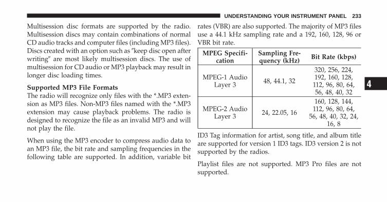
Multisession disc formats are supported by the radio.Multisession discs may contain combinations of normalCD audio tracks and computer files (including MP3 files).Discs created with an option such as �keep disc open afterwriting� are most likely multisession discs. The use ofmultisession for CD audio or MP3 playback may result inlonger disc loading times.
Supported MP3 File FormatsThe radio will recognize only files with the *.MP3 exten-sion as MP3 files. Non-MP3 files named with the *.MP3extension may cause playback problems. The radio isdesigned to recognize the file as an invalid MP3 and willnot play the file.
When using the MP3 encoder to compress audio data toan MP3 file, the bit rate and sampling frequencies in thefollowing table are supported. In addition, variable bit
rates (VBR) are also supported. The majority of MP3 filesuse a 44.1 kHz sampling rate and a 192, 160, 128, 96 orVBR bit rate.
MPEG Specifi-cation
Sampling Fre-quency (kHz) Bit Rate (kbps)
MPEG-1 AudioLayer 3 48, 44.1, 32
320, 256, 224,192, 160, 128,
112, 96, 80, 64,56, 48, 40, 32
MPEG-2 AudioLayer 3 24, 22.05, 16
160, 128, 144,112, 96, 80, 64,
56, 48, 40, 32, 24,16, 8
ID3 Tag information for artist, song title, and album titleare supported for version 1 ID3 tags. ID3 version 2 is notsupported by the radios.
Playlist files are not supported. MP3 Pro files are notsupported.
4
UNDERSTANDING YOUR INSTRUMENT PANEL 233

Playback of MP3 FilesWhen a medium containing MP3 data is loaded, theradio checks all files on the medium. If the mediumcontains a lot of folders or files, the radio will take moretime to start playing the MP3 files.
Loading times for playback of MP3 files may be affectedby the following:
• Media - CD-RW media may take longer to load thanCD-R media
• Medium formats - Multisession discs may take longerto load than non-multisession discs
• Number of files and folders - Loading times willincrease with more files and folders
To increase the speed of disc loading, it is recommendedto use CD-R media and single-session discs. To create asingle-session disc, enable the “Disc at Once” optionbefore writing to the disc.
Operation Instructions - Auxiliary ModeThe auxiliary (AUX) jack is an audio input jack, whichallows the user to plug in a portable device, such as anMP3 player, or cassette player, and utilize the vehicle’saudio system to amplify the source and play through thevehicle speakers.
Pressing the DISC/AUX button will change the mode toauxiliary device if the AUX jack is connected.
NOTE: The AUX device must be turned on and thedevice’s volume set to proper level. If the AUX audio isnot loud enough, turn the device’s volume up. If the AUXaudio sounds distorted, turn the device’s volume down.
TIME Button (Auxiliary Mode)Press this button to change the display to time of day. Thetime of day will display for five seconds (when ignition isOFF).
234 UNDERSTANDING YOUR INSTRUMENT PANEL
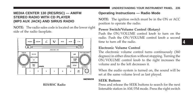
MEDIA CENTER 130 (RES/RSC) — AM/FMSTEREO RADIO WITH CD PLAYER(MP3 AUX JACK) AND SIRIUS RADIO
NOTE: The radio sales code is located on the lower rightside of the radio faceplate.
Operating Instructions — Radio Mode
NOTE: The ignition switch must be in the ON or ACCposition to operate the radio.
Power Switch/Volume Control (Rotary)Push the ON/VOLUME control knob to turn on theradio. Push the ON/VOLUME control knob a secondtime to turn off the radio.
Electronic Volume ControlThe electronic volume control turns continuously (360degrees) in either direction without stopping. Turning theON/VOLUME control knob to the right increases thevolume and to the left decreases it.
When the audio system is turned on, the sound will beset at the same volume level as last played.
SEEK ButtonsPress and release the SEEK buttons to search for the nextlistenable station in AM/FM mode. Press the right switch
RES/RSC Radio
4
UNDERSTANDING YOUR INSTRUMENT PANEL 235

to seek up and the left switch to seek down. The radiowill remain tuned to the new station until you makeanother selection. Holding either button will bypassstations without stopping until you release it.
Voice Command System (Radio) — If EquippedRefer to “Voice Command” in “Understanding The Fea-tures If Your Vehicle”.
Voice Command Button Uconnect™ Phone —If EquippedPress this button to operate the Uconnect™ Phone feature(if equipped). Refer to “Uconnect™ Phone” in “Under-standing The Features If Your Vehicle”.
If your vehicle is not equipped with or this feature is notavailable on your vehicle, a “Not Equipped WithUconnect” message will display on the radio screen.
Phone Button Uconnect™ Phone — If EquippedPress this button to operate the Uconnect™ Phone feature(if equipped). Refer to “Uconnect™ Phone” in “Under-standing The Features If Your Vehicle”.
If your vehicle is not equipped with or this feature is notavailable on your vehicle, a “Not Equipped WithUconnect” message will display on the radio screen.
TIME ButtonPress the TIME button to alternate display of the timeand radio frequency.
Clock Setting Procedure
1. Press and hold the TIME button until the hours blink.
2. Adjust the hours by turning the right side TUNE/SCROLL control knob.
236 UNDERSTANDING YOUR INSTRUMENT PANEL

3. After adjusting the hours, press the right side TUNE/SCROLL control knob to set the minutes. The minuteswill begin to blink.
4. Adjust the minutes using the right side TUNE/SCROLL control knob. Press the TUNE/SCROLL controlknob to save time change.
5. To exit, press any button/knob or wait five seconds.
The clock can also be set by pressing the SETUP button.For vehicles equipped with satellite radio, press theSETUP button, use the TUNE/SCROLL control to selectSET CLOCK, and then follow the above procedure,starting at Step 2. For vehicles not equipped with satelliteradio, press the SETUP button and then follow the aboveprocedure, starting at Step 2.
INFO ButtonPress the INFO button for an RDS station (one with callletters displayed). The radio will return a Radio Textmessage broadcast from an FM station (FM mode only).
RW/FFPressing the RW (Rewind) or FF (Fast Forward) buttonscauses the tuner to search for the next frequency in thedirection of the arrows. This feature operates in eitherAM or FM frequencies.
TUNE ControlTurn the rotary TUNE/SCROLL control knob clockwiseto increase or counterclockwise to decrease the frequency.
Setting the Tone, Balance, and FadePush the rotary TUNE/SCROLL control knob and BASSwill display. Turn the TUNE/SCROLL control knob tothe right or left to increase or decrease the bass tones.
4
UNDERSTANDING YOUR INSTRUMENT PANEL 237

Push the rotary TUNE/SCROLL control knob a secondtime and MID will display. Turn the TUNE/SCROLLcontrol knob to the right or left to increase or decrease themid-range tones.
Push the rotary TUNE/SCROLL control knob a thirdtime and TREBLE will display. Turn the TUNE/SCROLLcontrol knob to the right or left to increase or decrease thetreble tones.
Push the rotary TUNE/SCROLL control knob a fourthtime and BALANCE will display. Turn the TUNE/SCROLL control knob to the right or left to adjust thesound level from the right or left side speakers.
Push the rotary TUNE/SCROLL control knob a fifth timeand FADE will display. Turn the TUNE/SCROLL controlknob to the left or right to adjust the sound level betweenthe front and rear speakers.
Push the rotary TUNE/SCROLL control knob again toexit setting tone, balance, and fade.
MUSIC TYPE ButtonPressing this button once will turn on the Music Typemode for five seconds. Pressing the MUSIC TYPE buttonor turning the TUNE/SCROLL control knob within fiveseconds will allow the program format type to be se-lected. Many radio stations do not currently broadcastMusic Type information.
Toggle the MUSIC TYPE button to select the followingformat types:
Program Type 16-Digit Character DisplayNo program type or
undefined None
Adult Hits Adlt HitClassical Classicl
Classic Rock Cls RockCollege CollegeCountry Country
Foreign Language Language
238 UNDERSTANDING YOUR INSTRUMENT PANEL

Program Type 16-Digit Character DisplayInformation Inform
Jazz JazzNews News
Nostalgia NostalgaOldies Oldies
Personality PersnltyPublic Public
Rhythm and Blues R & BReligious Music Rel MuscReligious Talk Rel Talk
Rock RockSoft Soft
Soft Rock Soft RckSoft Rhythm and Blues Soft R&B
Sports SportsTalk Talk
Program Type 16-Digit Character DisplayTop 40 Top 40
Weather Weather
By pressing the SEEK button when the Music Type iconis displayed, the radio will be tuned to the next frequencystation with the same selected Music Type name. TheMusic Type function only operates when in the FMmode.
If a preset button is activated while in the Music Type(Program Type) mode, the Music Type mode will beexited and the radio will tune to the preset station.
SETUP ButtonPressing the SETUP button allows you to select betweenthe following items:
• Set Clock — Pressing the SELECT button will allowyou to set the clock. Adjust the hours by turning theTUNE/SCROLL control knob. After adjusting the
4
UNDERSTANDING YOUR INSTRUMENT PANEL 239
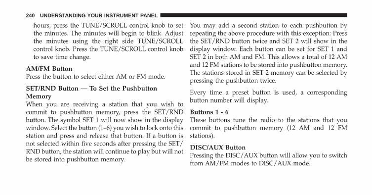
hours, press the TUNE/SCROLL control knob to setthe minutes. The minutes will begin to blink. Adjustthe minutes using the right side TUNE/SCROLLcontrol knob. Press the TUNE/SCROLL control knobto save time change.
AM/FM ButtonPress the button to select either AM or FM mode.
SET/RND Button — To Set the PushbuttonMemoryWhen you are receiving a station that you wish tocommit to pushbutton memory, press the SET/RNDbutton. The symbol SET 1 will now show in the displaywindow. Select the button (1–6) you wish to lock onto thisstation and press and release that button. If a button isnot selected within five seconds after pressing the SET/RND button, the station will continue to play but will notbe stored into pushbutton memory.
You may add a second station to each pushbutton byrepeating the above procedure with this exception: Pressthe SET/RND button twice and SET 2 will show in thedisplay window. Each button can be set for SET 1 andSET 2 in both AM and FM. This allows a total of 12 AMand 12 FM stations to be stored into pushbutton memory.The stations stored in SET 2 memory can be selected bypressing the pushbutton twice.
Every time a preset button is used, a correspondingbutton number will display.
Buttons 1 - 6These buttons tune the radio to the stations that youcommit to pushbutton memory (12 AM and 12 FMstations).
DISC/AUX ButtonPressing the DISC/AUX button will allow you to switchfrom AM/FM modes to DISC/AUX mode.
240 UNDERSTANDING YOUR INSTRUMENT PANEL
Operation Instructions — CD MODE for CD andMP3 Audio Play
NOTE:• The ignition switch must be in the ON or ACC
position to operate the radio.
• This radio is capable of playing compact discs (CD),recordable compact discs (CD-R), rewritable compactdiscs (CD-RW), compact discs with MP3 tracks andmultisession compact discs with CD and MP3 tracks.
Inserting Compact Disc(s)Gently insert one CD into the CD player with the CDlabel facing up. The CD will automatically be pulled intothe CD player and the CD icon will illuminate on theradio display. If a CD does not go into the slot more than1.0 in (2.5 cm), a disc may already be loaded and must beejected before a new disc can be loaded.
If you insert a disc with the ignition ON and the radioON, the unit will switch from radio to CD mode andbegin to play when you insert the disc. The display willshow the track number, and index time in minutes andseconds. Play will begin at the start of track 1.
CAUTION!
• This CD player will accept 4–3/4 in (12 cm) discsonly. The use of other sized discs may damage theCD player mechanism.
• Do not use adhesive labels. These labels can peelaway and jam the player mechanism.
• RES is a single CD player. Do not attempt to inserta second CD if one is already loaded.
• Dual-media disc types (one side is a DVD, theother side is a CD) should not be used, and theycan cause damage to the player.
4
UNDERSTANDING YOUR INSTRUMENT PANEL 241
EJECT Button - Ejecting a CDPress the EJECT button to eject the CD.
If you have ejected a disc and have not removed it within10 seconds, it will be reloaded. If the CD is not removed,the radio will reinsert the CD but will not play it.
A disc can be ejected with the radio and ignition OFF.
NOTE: Ejecting with the ignition OFF is not allowed onconvertible or soft-top models (if equipped).
SEEK ButtonPress the right SEEK button for the next selection on theCD. Press the left SEEK button to return to the beginningof the current selection, or return to the beginning of theprevious selection if the CD is within the first second of
the current selection. Pressing and holding the SEEKbutton will allow faster scrolling through the tracks inCD and MP3 modes.
TIME ButtonPress this button to change the display from a large CDplaying time display to a small CD playing time display.
RW/FFPress and hold FF (Fast Forward) and the CD player willbegin to fast forward until FF is released or RW oranother CD button is pressed. The RW (Reverse) buttonworks in a similar manner.
AM/FM ButtonPress the button to select either AM or FM mode.
242 UNDERSTANDING YOUR INSTRUMENT PANEL

SET/RND Button (Random Play Button)Press this button while the CD is playing to activateRandom Play. This feature plays the selections on thecompact disc in random order to provide an interestingchange of pace.
Press the right SEEK button to move to the next ran-domly selected track.
Press the SET/RND button a second time to stop Ran-dom Play.
Notes On Playing MP3 FilesThe radio can play MP3 files; however, acceptable MP3file recording media and formats are limited. Whenwriting MP3 files, pay attention to the following restric-tions.
Supported Media (Disc Types)The MP3 file recording media supported by the radio areCDDA, CD-R, CD-RW, MP3, and CDDA+MP3.
Supported Medium Formats (File Systems)The medium formats supported by the radio are ISO 9660Level 1 and Level 2 and includes the Joliet extension.When reading discs recorded using formats other thanISO 9660 Level 1 and Level 2, the radio may fail to readfiles properly and may be unable to play the file nor-mally. UDF and Apple HFS formats are not supported.
The radio uses the following limits for file systems:
• Maximum number of folder levels: 8
• Maximum number of files: 255
• Maximum number of folders. (The radio display of filenames and folder names is limited. For large numbersof files and/or folders, the radio may be unable todisplay the file name and folder name and will assigna number instead. With a maximum number of files,exceeding 20 folders will result in this display. With 200files, exceeding 50 folders will result in this display.)
4
UNDERSTANDING YOUR INSTRUMENT PANEL 243

• Maximum number of characters in file/folder names:
• Level 1: 12 (including a separator �.� and a three-character extension)
• Level 2: 31 (including a separator �.� and a three-character extension)
Multisession disc formats are supported by the radio.Multisession discs may contain combinations of normalCD audio tracks and computer files (including MP3 files).Discs created with an option such as �keep disc open afterwriting� are most likely multisession discs. The use ofmultisession for CD audio or MP3 playback may result inlonger disc loading times.
Supported MP3 File FormatsThe radio will recognize only files with the *.MP3 exten-sion as MP3 files. Non-MP3 files named with the *.MP3
extension may cause playback problems. The radio isdesigned to recognize the file as an invalid MP3 and willnot play the file.
When using the MP3 encoder to compress audio data toan MP3 file, the bit rate and sampling frequencies in thefollowing table are supported. In addition, variable bitrates (VBR) are also supported. The majority of MP3 filesuse a 44.1 kHz sampling rate and a 192, 160, 128, 96 orVBR bit rates.
MPEGSpecification
SamplingFrequency (kHz) Bit Rate (kbps)
MPEG-1 AudioLayer 3 48, 44.1, 32
320, 256, 224,192, 160, 128,
112, 96, 80, 64,56, 48, 40, 32
MPEG-2 AudioLayer 3 24, 22.05, 16
160, 128, 144,112, 96, 80, 64,
56, 48, 40, 32, 24,16, 8
244 UNDERSTANDING YOUR INSTRUMENT PANEL

ID3 Tag information for artist, song title, and album titleare supported for version 1 ID3 tags. ID3 version 2 is notsupported by the radios.
Playlist files are not supported. MP3 Pro files are notsupported.
Playback of MP3 FilesWhen a medium containing MP3 data is loaded, theradio checks all files on the medium. If the mediumcontains a lot of folders or files, the radio will take moretime to start playing the MP3 files.
Loading times for playback of MP3 files may be affectedby the following:
• Media - CD-RW media may take longer to load thanCD-R media
• Medium formats - Multisession discs may take longerto load than non-multisession discs
• Number of files and folders - Loading times willincrease with more files and folders
To increase the speed of disc loading, it is recommendedto use CD-R media and single-session discs. To create asingle-session disc, enable the “Disc at Once” optionbefore writing to the disc.
LIST Button (CD Mode for MP3 Play)Pressing the LIST button will bring up a list of all folderson the disc. Scrolling up or down the list is done byturning the TUNE/SCROLL control knob. Selecting afolder by pressing the TUNE/SCROLL control knob willbegin playing the files contained in that folder (or thenext folder in sequence if the selection does not containplayable files).
The folder list will time out after five seconds.
4
UNDERSTANDING YOUR INSTRUMENT PANEL 245

INFO Button (CD Mode for MP3 Play)Pressing the INFO button repeatedly will scroll throughthe following TAG information: Song Title, Artist, FileName, and Folder Name (if available).
Press the INFO button once more to return to �elapsedtime� priority mode.
Press and hold the INFO button for three seconds ormore and the radio will display song titles for each file.
Press and hold the INFO button again for three secondsto return to �elapsed time� display.
Operation Instructions - Auxiliary ModeThe auxiliary (AUX) jack is an audio input jack whichallows the user to plug in a portable device such as anMP3 player or cassette player and utilize the vehicle’saudio system to amplify the source and play through thevehicle speakers.
Pressing the AUX button will change the mode to auxil-iary device if the AUX jack is connected.
NOTE: The AUX device must be turned on and thedevice’s volume set to the proper level. If the AUX audio isnot loud enough, turn the device’s volume up. If the AUXaudio sounds distorted, turn the device’s volume down.
TIME Button (Auxiliary Mode)Press this button to change the display to time of day. Thetime of day will display for five seconds (when theignition is OFF).
Operating Instructions - Uconnect™ Phone(If Equipped)Refer to “Uconnect™ Phone” in “Understanding TheFeatures If Your Vehicle”.
Operating Instructions - Uconnect™ Multimedia(Satellite Radio) (If Equipped)Refer to “Uconnect™ Multimedia (Satellite Radio)”.
246 UNDERSTANDING YOUR INSTRUMENT PANEL
UNIVERSAL CONSUMER INTERFACE (UCI) — IFEQUIPPED
NOTE: This section is for sales code RES and REQ/REL/RET radios only with uconnect™. For sales codeRER, RBZ, REN, REP, REW, RB2 or REZ touch-screenradio UCI feature, refer to the separate RER, REN, RBZ,RB2 or REZ User’s Manual. UCI is available only ifequipped as an option with these radios.
This feature allows you to plug an iPod� into thevehicle’s sound system through a 16–pin connector, usingthe provided interface cable.
UCI supports Mini, 4G, Photo, Nano, 5G iPod� andiPhone� devices. Some iPod� software versions may notfully support the UCI features. Please visit Apple’swebsite for software updates.
NOTE:• If the radio has a USB port, connecting an iPod� to this
port does not play the media. For playing an iPod�,use the separate 16–pin connector port (in the glovecompartment on some vehicles).
• Connecting an iPod� to the AUX port located in theradio faceplate, plays media, but does not use the UCIfeature to control the connected device.
Connecting The iPod�Use the provided connection cable to connect an iPod� tothe vehicle’s 16–pin connector port (which is located inthe glove compartment on some vehicles). Once theiPod� is connected and synchronized to the vehicle’s UCIsystem (iPod� may take a few seconds to connect), theiPod� starts charging and is ready for use by pressingradio switches, as described below.
4
UNDERSTANDING YOUR INSTRUMENT PANEL 247

NOTE:• You may have to remove the connector pin protection
cap from the 16–pin connector port, prior to connect-ing the cable.
• If the iPod� battery is completely discharged, it maynot communicate with the UCI system until a mini-mum charge is attained. Leaving the iPod� connectedto the UCI system may charge it to the required level.
Using This FeatureBy using the provided connection cable to connect aniPod� to the vehicle’s UCI 16–pin connector port:
• The iPod� audio can be played on the vehicle’s soundsystem, providing metadata (artist, track title, album,etc.) information on the radio display.
• The iPod� can be controlled using the radio buttons toPlay, Browse, and List the iPod� contents.
• The iPod� battery charges when plugged into the UCIconnector (if supported by the specific iPod� device)
Controlling The iPod� Using Radio ButtonsTo get into the UCI (iPod�) mode and access a connectediPod�, press the “AUX” button on the radio faceplate.Once in the UCI (iPod�) mode, iPod� audio tracks (ifavailable from iPod�) start playing over the vehicle’saudio system.
Play ModeWhen switched to UCI mode, the iPod� automaticallystarts Play mode. In Play mode, you may use thefollowing buttons on the radio faceplate to control theiPod� and display data:
• Use the TUNE control knob to select the next orprevious track.
• Turning it clockwise (forward) by one click, whileplaying a track, skips to the next track.
248 UNDERSTANDING YOUR INSTRUMENT PANEL

• Turning it counterclockwise (backward) by oneclick, during the first two seconds of the track, willjump to the previous track in the list. Turning thisbutton at any other time in the track, will jump tothe beginning of the current track.
• Jump backward in the current track by pressing andholding the << RW button. Holding the << RWbutton long enough will take you to the beginningof the current track.
• Jump forward in the current track by pressing andholding the FF >> button.
• A single press backward << RW or forward FF >> willjump backward or forward respectively, for fiveseconds.
• Use the << SEEK and SEEK >> buttons to jump to theprevious or next track. If the << SEEK button ispressed during the first two seconds of the track, it will
jump to the previous track in the list; if you press thisbutton at any other time in the track, it will jump to thebeginning of the track. If you press the SEEK >>button during play mode, it will jump to the next trackin the list.
• While a track is playing, press the INFO button to seethe associated metadata (artist, track title, album, etc.)for that track. Pressing the INFO button again jumpsto the next screen of data for that track. Once you haveseen all screens, the last INFO button press will takeyou back to the play mode screen on the radio.
• Pressing the REPEAT button will change the iPod�mode to repeat the current playing track.
• Press the SCAN button to use iPod� scan mode, whichwill play the first five seconds of each track in thecurrent list and then forward to the next song. To stopSCAN mode and start playing the desired track, whenit is playing the track, press the SCAN button again.
4
UNDERSTANDING YOUR INSTRUMENT PANEL 249
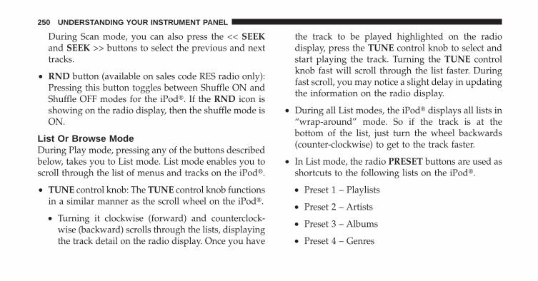
During Scan mode, you can also press the << SEEKand SEEK >> buttons to select the previous and nexttracks.
• RND button (available on sales code RES radio only):Pressing this button toggles between Shuffle ON andShuffle OFF modes for the iPod�. If the RND icon isshowing on the radio display, then the shuffle mode isON.
List Or Browse ModeDuring Play mode, pressing any of the buttons describedbelow, takes you to List mode. List mode enables you toscroll through the list of menus and tracks on the iPod�.
• TUNE control knob: The TUNE control knob functionsin a similar manner as the scroll wheel on the iPod�.
• Turning it clockwise (forward) and counterclock-wise (backward) scrolls through the lists, displayingthe track detail on the radio display. Once you have
the track to be played highlighted on the radiodisplay, press the TUNE control knob to select andstart playing the track. Turning the TUNE controlknob fast will scroll through the list faster. Duringfast scroll, you may notice a slight delay in updatingthe information on the radio display.
• During all List modes, the iPod� displays all lists in“wrap-around” mode. So if the track is at thebottom of the list, just turn the wheel backwards(counter-clockwise) to get to the track faster.
• In List mode, the radio PRESET buttons are used asshortcuts to the following lists on the iPod�.
• Preset 1 – Playlists
• Preset 2 – Artists
• Preset 3 – Albums
• Preset 4 – Genres
250 UNDERSTANDING YOUR INSTRUMENT PANEL
• Preset 5 – Audiobooks
• Preset 6 – Podcasts
• Pressing a PRESET button will display the currentlist on the top line and the first item in that list onthe second line.
• To Exit List mode without selecting a track, press thesame PRESET button again to go back to Playmode.
• LIST button: The LIST button will display the toplevel menu of the iPod�. Turn the TUNE control knobto list the top-menu item you wish to select and pressthe TUNE control knob. This will display the nextsub-menu list item on the iPod� then you can followthe same steps to go to the desired track in that list.Not all iPod� sub-menu levels are available on thissystem.
• MUSIC TYPE button: The MUSIC TYPE button isanother shortcut button to the genre listing on youriPod�.
CAUTION!
• Leaving the iPod� (or any supported device) any-where in the vehicle in extreme heat or cold canalter the operation or damage the device. Followthe device manufacturer’s guidelines.
• Placing items on the iPod�, or connections to theiPod� in the vehicle, can cause damage to thedevice and/or to the connectors.
WARNING!
Do not plug in or remove the iPod� while driving.Failure to follow this warning could result in anaccident.
4
UNDERSTANDING YOUR INSTRUMENT PANEL 251
Uconnect™ Multimedia (SATELLITE RADIO) — IFEQUIPPED (REN/REQ/RER/RES/REU/RBZRADIOS ONLY)Satellite radio uses direct satellite-to-receiver broadcast-ing technology to provide clear digital sound, coast tocoast. The subscription service provider is Sirius SatelliteRadio. This service offers over 130 channels of music,sports, news, entertainment, and programming for chil-dren, directly from its satellites and broadcasting studios.
NOTE: Sirius service is not available in Hawaii and haslimited coverage in Alaska.
System ActivationSirius Satellite Radio service is pre-activated and youmay begin listening immediately to the one year of audioservice that is included with the factory-installed satelliteradio system in your vehicle. Sirius will supply a wel-come kit that contains general information, includinghow to setup your on-line listening account. For further
information, call the toll-free number 888-539-7474, orvisit the Sirius web site at www.sirius.com, or at www-.siriuscanada.ca for Canadian residents.
Electronic Serial Number/Sirius IdentificationNumber (ESN/SID)Please have the following information available whencalling:
1. The Electronic Serial Number/Sirius IdentificationNumber (ESN/SID).
2. Your Vehicle Identification Number.
To access the ESN/SID, refer to the following steps:
ESN/SID Access With REQ/RES RadiosWith the ignition switch in the ON/RUN or ACC posi-tion and the radio on, press the SETUP button and scrollusing the TUNE/SCROLL control knob until Sirius ID isselected. Press the TUNE/SCROLL control knob and the
252 UNDERSTANDING YOUR INSTRUMENT PANEL
Sirius ID number will display. The Sirius ID numberdisplay will time out in two minutes. Press any button onthe radio to exit this screen.
ESN/SID Access With REN/RER/RBZ RadiosWhile in SAT mode, press the MENU button on the radiofaceplate.
Next, touch the SUBSCRIPTION tab on the touch screen.All the ESNs that apply to your vehicle will display.
ESN/SID Access With REU RadioWhile in SAT mode, press the MENU button on the radiofaceplate.
Next, turn the knob surrounding the joystick in the centerof the radio to scroll to Subscription, and then press andrelease the joystick. All of the ESNs that apply to yourvehicle will display.
Selecting Uconnect™ Multimedia (Satellite) ModePress the SAT button until �SAT� appears in the display. ACD may remain in the radio while in the Satellite radiomode.
Satellite AntennaTo ensure optimum reception, do not place items on theroof around the rooftop antenna location or strap items tothe trunk lid around the trunk lid antenna (if equipped).Metal objects placed within the line of sight of theantenna will cause decreased performance. Larger lug-gage items such as bikes should be placed as far rearwardas possible, within the loading design of the rack. Do notplace items directly on or above the antenna.
Reception QualitySatellite reception may be interrupted due to one of thefollowing reasons:
• The vehicle is parked in an underground parkingstructure or under a physical obstacle.
4
UNDERSTANDING YOUR INSTRUMENT PANEL 253

• Dense tree coverage may interrupt reception in theform of short audio mutes.
• Driving under wide bridges or along tall buildings cancause intermittent reception.
• Placing objects over or too close to the antenna cancause signal blockage.
Operating Instructions — Uconnect™ Multimedia(Satellite) Mode
NOTE: The ignition switch must be in the ON or ACCposition to operate the radio.
SEEK ButtonsPress and release the SEEK buttons to search for the nextchannel in Satellite mode. Press the right switch to seekup and the left switch to seek down. The radio willremain tuned to the new channel until you make anotherselection. Holding either button will bypass channelswithout stopping until you release it.
SCAN Button (When Equipped)Pressing the SCAN button causes the tuner to search forthe next channel, pausing for eight seconds before con-tinuing to the next. To stop the search, press the SCANbutton a second time.
INFO Button — Except REU RadioPressing the INFO button will cycle the display informa-tion between Artist, Song Title, and Composer (if avail-able). Also, pressing and holding the INFO button for anadditional three seconds will make the radio display thesong title all of the time (press and hold again to return tonormal display).
INFO Button — REU RadioPressing the INFO button will display information aboutArtist, Song Title, and Composer (if available). Pressingthe INFO button again will close the INFO screen.
254 UNDERSTANDING YOUR INSTRUMENT PANEL
RW/FFPressing the RW (Rewind) or FF (Fast Forward) buttonscauses the tuner to search for the next channel in thedirection of the arrows.
TUNE Control (Rotary)Turn the rotary TUNE/SCROLL control knob clockwiseto increase or counterclockwise to decrease the channel.
MUSIC TYPE Button — Except REU RadioPressing this button once will turn on the Music Typemode for five seconds. Pressing the MUSIC TYPE buttonor turning the TUNE/SCROLL control knob within fiveseconds will allow the program format type to be se-lected.
Toggle the MUSIC TYPE button again to select the musictype.
By pressing the SEEK button when the Music Typefunction is active, the radio will be tuned to the nextchannel with the same selected Music Type name.
If a preset button is activated while in the Music Type(Program Type) mode, the Music Type mode will beexited and the radio will tune to the preset channel.
MUSIC TYPE Button — REU RadioPressing this button provides a Music Type list fromwhich you can make a selection. Once a selection ismade, you can seek up or down or scan the channels andthe radio will tune to the next station matching theselected format. There is no time-out for this screen.Pressing the MUSIC TYPE button again will close theMusic Type screen. Once closed, seek up, seek down, andscan will no longer be based on your selection.
4
UNDERSTANDING YOUR INSTRUMENT PANEL 255

SETUP ButtonPressing the SETUP button allows you to select thefollowing items:
• Display Sirius ID number — Press the AUDIO/SELECT button to display the Sirius ID number. Thisnumber is used to activate, deactivate, or change theSirius subscription.
SET Button – To Set the Pushbutton MemoryWhen you are receiving a channel that you wish tocommit to pushbutton memory, press the SET button.The symbol SET 1 will now show in the display window.Select the button (1-6) you wish to lock onto this channeland press and release that button. If a button is notselected within five seconds after pressing the SET but-ton, the channel will continue to play but will not bestored into pushbutton memory.
You may add a second channel to each pushbutton byrepeating the above procedure with this exception: Pressthe SET button twice and SET 2 will show in the displaywindow. Each button can be set for SET 1 and SET 2. Thisallows a total of 12 Satellite channels to be stored intopushbutton memory. The channels stored in SET 2memory can be selected by pressing the pushbuttontwice.
Every time a preset button is used, a correspondingbutton number will display.
Buttons 1 - 6These buttons tune the radio to the channels that youcommit to pushbutton memory (12 Satellite stations).
256 UNDERSTANDING YOUR INSTRUMENT PANEL

Operating Instructions — Uconnect™ Phone(If Equipped)Refer to “Uconnect™ Phone” in “Understanding TheFeatures Of Your Vehicle”.
Operating Instructions — Video EntertainmentSystem (VES)™ (If Equipped)Refer to separate “Video Entertainment System (VES)™Guide.”
REMOTE SOUND SYSTEM CONTROLS — IFEQUIPPEDThe remote sound system controls are located on the rearsurface of the steering wheel. Reach behind the wheel toaccess the switches.
The right-hand control is a rocker type switch with apushbutton in the center. Pressing the top of the switchwill increase the volume, and pressing the bottom of theswitch will decrease the volume.
Remote Sound System Controls(Back View Of Steering Wheel)
4
UNDERSTANDING YOUR INSTRUMENT PANEL 257
The button located in the center of the right-hand controlwill switch modes to Radio or CD.
The left-hand control is a rocker type switch with apushbutton in the center. The function of the left-handcontrol is different depending on which mode you are in.
The following describes the left-hand control operation ineach mode.
Radio OperationPress the top of the switch to SEEK up for the nextlistenable station. Press the bottom of the switch to SEEKdown for the next listenable station.
The button located in the center of the left-hand controlwill tune to the next preset station that you have pro-grammed in the radio preset pushbuttons.
CD PlayerPress the top of the switch once to go to the next track onthe CD. Press the bottom of the switch once to go to the
beginning of the current track or to the beginning of theprevious track, if it is within one second after the currenttrack begins to play.
If you press the switch up or down twice it plays thesecond track, three times, it will play the third, etc.
The button in the center of the left-hand switch changesCD’s on the 6–Disc in-dash CD changer radio. Thisbutton does not function for all other radios.
CD/DVD DISC MAINTENANCETo keep a CD/DVD in good condition, take the followingprecautions:
1. Handle the disc by its edge; avoid touching thesurface.
2. If the disc is stained, clean the surface with a soft cloth,wiping from center to edge.
258 UNDERSTANDING YOUR INSTRUMENT PANEL
3. Do not apply paper or tape to the disc; avoid scratch-ing the disc.
4. Do not use solvents such as benzene, thinner, cleaners,or anti-static sprays.
5. Store the disc in its case after playing.
6. Do not expose the disc to direct sunlight.
7. Do not store the disc where temperatures may becometoo high.
NOTE: If you experience difficulty in playing a particu-lar disc, it may be damaged (i.e., scratched, reflectivecoating removed, a hair, moisture or dew on the disc)oversized, or have protection encoding. Try a knowngood disc before considering disc player service.
RADIO OPERATION AND CELLULAR PHONESUnder certain conditions, the cellular phone being on inyour vehicle can cause erratic or noisy performance fromyour radio. This condition may be lessened or eliminatedby relocating the cellular phone antenna. This conditionis not harmful to the radio. If your radio performancedoes not satisfactorily “clear” by the repositioning of theantenna, it is recommended that the radio volume beturned down or off during cellular phone operation.
CLIMATE CONTROLSThe Air Conditioning and Heating System is designed tomake you comfortable in all types of weather.
4
UNDERSTANDING YOUR INSTRUMENT PANEL 259
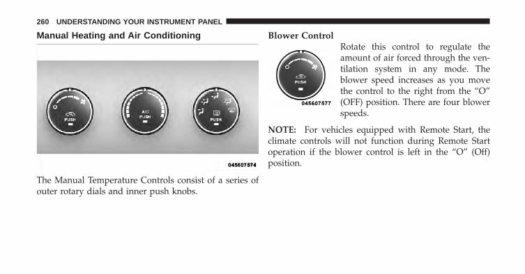
Manual Heating and Air Conditioning
The Manual Temperature Controls consist of a series ofouter rotary dials and inner push knobs.
Blower ControlRotate this control to regulate theamount of air forced through the ven-tilation system in any mode. Theblower speed increases as you movethe control to the right from the “O”(OFF) position. There are four blowerspeeds.
NOTE: For vehicles equipped with Remote Start, theclimate controls will not function during Remote Startoperation if the blower control is left in the “O” (Off)position.
260 UNDERSTANDING YOUR INSTRUMENT PANEL

Temperature ControlRotate this control to regulate the tem-perature of the air inside the passengercompartment. Rotating the dial leftinto the blue area of the scale indicatescooler temperatures while rotatingright into the red area indicateswarmer temperatures.
NOTE: If your air conditioning performance seemslower than expected, check the front of the A/C con-denser located in front of the radiator for an accumula-tion of dirt or insects. Clean with a gentle water sprayfrom behind the radiator and through the condenser.Fabric front fascia protectors may reduce airflow to thecondenser, reducing air conditioning performance.
Mode Control (Air Direction)Rotate this control to choose from sev-eral patterns of air distribution. Youcan select either a primary mode asidentified by the symbols on the con-trol, or a blend of two of these modes.The closer the setting is to a particularsymbol, the more air distribution you
receive from that mode.
PanelAir is directed through the outlets in the instrumentpanel. These outlets can be adjusted to direct airflow.
NOTE: The center instrument panel outlets can beaimed so that they are directed toward the rear seatpassengers for maximum airflow to the rear.
Bi-LevelAir is directed through the panel and floor outlets.
4
UNDERSTANDING YOUR INSTRUMENT PANEL 261

NOTE: For all settings except full cold or full hot, thereis a difference in temperature between the upper andlower outlets. The warmer air flows to the floor outlets.This feature gives improved comfort during sunny butcool conditions.
FloorAir is directed through the floor outlets with asmall amount flowing through the defrost and side
window demist outlets.
MixAir is directed through the floor, defrost, and sidewindow demist outlets. This setting works best incold or snowy conditions that require extra heat to
the windshield. This setting is good for maintainingcomfort while reducing moisture on the windshield.
DefrostAir is directed through the windshield and sidewindow demist outlets. Use this mode with maxi-
mum blower and temperature settings for best wind-shield and side window defrosting.
NOTE: The air conditioning compressor operates inMix, Defrost, or a blend of these modes, even if the AirConditioning (A/C) button is not pressed. This dehu-midifies the air to help dry the windshield. To improvefuel economy, use these modes only when necessary.
Recirculation ControlPressing the Recirculation Control button willput the system in recirculation mode. This canbe used when outside conditions such assmoke, odors, dust, or high humidity are
present. Activating recirculation will cause the LED in thecontrol button to illuminate.
262 UNDERSTANDING YOUR INSTRUMENT PANEL
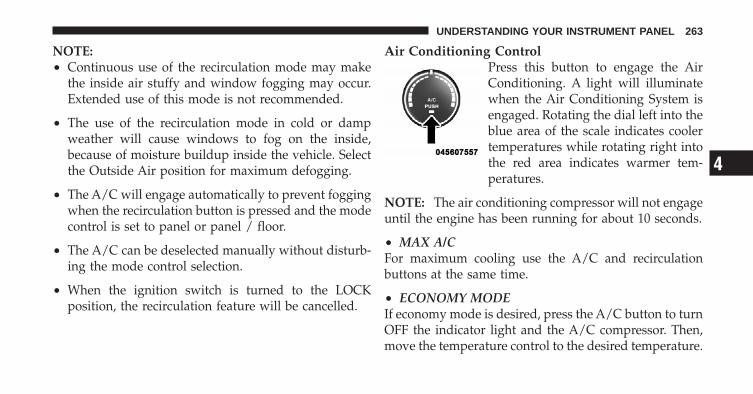
NOTE:• Continuous use of the recirculation mode may make
the inside air stuffy and window fogging may occur.Extended use of this mode is not recommended.
• The use of the recirculation mode in cold or dampweather will cause windows to fog on the inside,because of moisture buildup inside the vehicle. Selectthe Outside Air position for maximum defogging.
• The A/C will engage automatically to prevent foggingwhen the recirculation button is pressed and the modecontrol is set to panel or panel / floor.
• The A/C can be deselected manually without disturb-ing the mode control selection.
• When the ignition switch is turned to the LOCKposition, the recirculation feature will be cancelled.
Air Conditioning ControlPress this button to engage the AirConditioning. A light will illuminatewhen the Air Conditioning System isengaged. Rotating the dial left into theblue area of the scale indicates coolertemperatures while rotating right intothe red area indicates warmer tem-peratures.
NOTE: The air conditioning compressor will not engageuntil the engine has been running for about 10 seconds.
• MAX A/CFor maximum cooling use the A/C and recirculationbuttons at the same time.
• ECONOMY MODEIf economy mode is desired, press the A/C button to turnOFF the indicator light and the A/C compressor. Then,move the temperature control to the desired temperature.
4
UNDERSTANDING YOUR INSTRUMENT PANEL 263

Automatic Temperature Control (ATC) —If EquippedThe Automatic Temperature Control system automati-cally maintains the climate in the cabin of the vehicle atthe comfort levels desired by the driver and passenger.
Automatic OperationOperation of the system is quite simple.
1. Turn the Mode Control knob (on the right) and theBlower Control knob (on the left) to AUTO.
NOTE: The AUTO position performs best for front seatoccupants only.
2. Dial in the temperature you wouldlike the system to maintain by rotatingthe Temperature Control knob. Oncethe comfort level is selected, the sys-tem will maintain that level automati-cally using the heating system. Shouldthe desired comfort level require air
conditioning, the system will automatically make theadjustment.
Automatic Temperature Control
264 UNDERSTANDING YOUR INSTRUMENT PANEL

You will experience the greatest efficiency by simplyallowing the system to function automatically. Selectingthe “O” (OFF) position on the blower control stops thesystem completely and closes the outside air intake.
The recommended setting for maximum comfort for theaverage person is 72°F (22°C); however, this may vary.
NOTE:• The temperature setting can be adjusted at anytime
without affecting automatic operation.
• Pressing the Air Conditioning Control button while inAUTO mode will cause the LED in the control buttonto flash three times and then turn off. This indicatesthat the system is in AUTO mode and requesting theair conditioning is not necessary.
• If your air conditioning performance seems lower thanexpected, check the front of the A/C condenser locatedin front of the radiator for an accumulation of dirt orinsects. Clean with a gentle water spray from behindthe radiator and through the condenser. Fabric frontfascia protectors may reduce airflow to the condenser,reducing air conditioning performance.
4
UNDERSTANDING YOUR INSTRUMENT PANEL 265

Blower ControlFor full automatic operation or forautomatic blower operation turn theknob to AUTO position. In manualmode there are seven blower speedsthat can be individual selected. In offposition the blower will shut off.
Manual OperationThis system offers a full complement of manual overridefeatures, which consist of Blower Preferred Automatic,Mode Preferred Automatic, or Blower and Mode Pre-ferred Automatic. This means the operator can overridethe blower, the mode, or both. There is a manual blowerrange for times when the AUTO setting is not desired.The blower can be set to any fixed blower speed byrotating the Blower Control knob (on the left).
NOTE: Please read the Automatic Temperature ControlOperation Chart that follows for details.
266 UNDERSTANDING YOUR INSTRUMENT PANEL

4
UNDERSTANDING YOUR INSTRUMENT PANEL 267
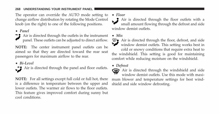
The operator can override the AUTO mode setting tochange airflow distribution by rotating the Mode Controlknob (on the right) to one of the following positions.
• PanelAir is directed through the outlets in the instrumentpanel. These outlets can be adjusted to direct airflow.
NOTE: The center instrument panel outlets can beaimed so that they are directed toward the rear seatpassengers for maximum airflow to the rear.
• Bi-LevelAir is directed through the panel and floor outlets.
NOTE: For all settings except full cold or full hot, thereis a difference in temperature between the upper andlower outlets. The warmer air flows to the floor outlets.This feature gives improved comfort during sunny butcool conditions.
• FloorAir is directed through the floor outlets with asmall amount flowing through the defrost and side
window demist outlets.
• MixAir is directed through the floor, defrost, and sidewindow demist outlets. This setting works best incold or snowy conditions that require extra heat to
the windshield. This setting is good for maintainingcomfort while reducing moisture on the windshield.
• DefrostAir is directed through the windshield and sidewindow demist outlets. Use this mode with maxi-
mum blower and temperature settings for best wind-shield and side window defrosting.
268 UNDERSTANDING YOUR INSTRUMENT PANEL

• Air Conditioner ControlPress this button to turn on the airconditioning during manual operationonly. When the air conditioning isturned on, cool dehumidified air willflow through the outlets selected withthe Mode control dial. Press this but-ton a second time to turn OFF the air
conditioning. An LED in the button illuminates whenmanual compressor operation is selected.
• Recirculation ControlThe system will automatically control recircu-lation. However, pressing the RecirculationControl button will put the system in recircu-lation mode. This can be used when outside
conditions such as smoke, odors, dust, or high humidityare present. Activating recirculation will cause the LED inthe control button to illuminate.
NOTE:• When the ignition switch is turned to the LOCK
position, the recirculation feature will be cancelled.
• In cold weather, use of the Recirculation mode maylead to excessive window fogging. The Recirculationmode is not allowed in the floor, defrost, or defrost/floor mode in order to improve window clearing.Recirculation will be disabled automatically if thesemodes are selected.
• Extended use of recirculation may cause the windowsto fog. If the interior of the windows begins to fog,press the Recirculation button to return to outside air.Some temp/humidity conditions will cause capturedinterior air to condense on windows and hampervisibility. For this reason, the system will not allowRecirculation to be selected while in floor, defrost, ordefrost/floor mode. Attempting to use the recircula-tion while in these modes will cause the LED in thecontrol button to blink and then turn off.
4
UNDERSTANDING YOUR INSTRUMENT PANEL 269

• Most of the time, when in Automatic Operation, youcan temporarily put the system into RecirculationMode by pressing the Recirculation button. However,under certain conditions, while in Automatic Mode,the system is blowing air out the defrost vents. Whenthese conditions are present, and the Recirculationbutton is pressed, the indicator will flash and then turnoff. This tells you that you are unable to go intoRecirculation Mode at this time. If you would like thesystem to go into Recirculation Mode, you must firstmove the Mode knob to Panel, Panel/Floor and thenpress the Recirculation button. This feature reduces thepossibility of window fogging.
Operating Tips
NOTE: Refer to the chart at the end of this section forsuggested control settings for various weather condi-tions.
Summer OperationThe engine cooling system in air-conditioned vehiclesmust be protected with a high-quality antifreeze coolantto provide proper corrosion protection and to protectagainst engine overheating. A solution of 50% ethyleneglycol antifreeze coolant and 50% water is recommended.Refer to “Maintenance Procedures” in “Maintaining YourVehicle” for proper coolant selection.
Winter OperationUse of the air Recirculation Mode during winter months isnot recommended because it may cause window fogging.
Vacation StorageAnytime you store your vehicle, or keep it out of service(i.e., vacation) for two weeks or more, run the airconditioning system at idle for about five minutes in thefresh air and high blower settings. This will ensureadequate system lubrication to minimize the possibilityof compressor damage when the system is started again.
270 UNDERSTANDING YOUR INSTRUMENT PANEL

Window FoggingInterior fogging on the windshield can be quickly re-moved by turning the mode selector to Defrost. TheDefrost/Floor mode can be used to maintain a clearwindshield and provide sufficient heating. If side win-dow fogging becomes a problem, increase blower speed.Vehicle windows tend to fog on the inside in mild butrainy or humid weather.
NOTE: Recirculate without A/C should not be used forlong periods as fogging may occur.
Side Window DemistersA side window demister outlet is located at each end ofthe instrument panel. These non-adjustable outlets directair toward the side windows when the system is in theFLOOR, MIX, or DEFROST mode. The air is directed atthe area of the windows through which you view theoutside mirrors.
Outside Air IntakeMake sure the air intake, located directly in front of thewindshield, is free of obstructions such as leaves. Leavescollected in the air intake may reduce airflow, and if theyenter the plenum, they could plug the water drains. Inwinter months, make sure the air intake is clear of ice,slush, and snow.
A/C Air Filter — If EquippedThe A/C Filter prevents most dust and pollen fromentering the cabin. The filter acts on air coming fromoutside the vehicle and recirculated air within the pas-senger compartment. Refer to “Maintenance Procedures”in “Maintaining Your Vehicle” for A/C Air Filter serviceinformation or see your authorized dealer for service.Refer to “Maintenance Schedules” for filter serviceintervals.
4
UNDERSTANDING YOUR INSTRUMENT PANEL 271
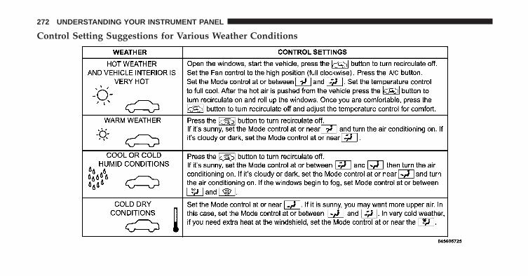
Control Setting Suggestions for Various Weather Conditions
272 UNDERSTANDING YOUR INSTRUMENT PANEL

STARTING AND OPERATING
CONTENTS
� Starting Procedures . . . . . . . . . . . . . . . . . . . . 277
▫ Manual Transaxle – If Equipped . . . . . . . . . . 277
▫ Automatic Transaxle – If Equipped . . . . . . . . 277
▫ Normal Starting . . . . . . . . . . . . . . . . . . . . . 278
▫ Extreme Cold Weather(Below �20°F Or �29°C) . . . . . . . . . . . . . . . 278
▫ If Engine Fails To Start . . . . . . . . . . . . . . . . 279
▫ After Starting . . . . . . . . . . . . . . . . . . . . . . . 279
� Engine Block Heater — If Equipped . . . . . . . . 279
� Manual Transaxle — If Equipped . . . . . . . . . . 280
▫ Five–Speed Manual Transaxle . . . . . . . . . . . 280
▫ Recommended Shift Speeds . . . . . . . . . . . . . 281
▫ Downshifting . . . . . . . . . . . . . . . . . . . . . . . 281
� Automatic Transaxle — If Equipped . . . . . . . . 282
▫ Brake/Transmission Interlock System . . . . . . 283
▫ Automatic Transaxle Ignition InterlockSystem . . . . . . . . . . . . . . . . . . . . . . . . . . . . 283
▫ Gear Ranges . . . . . . . . . . . . . . . . . . . . . . . . 284
5
� AutoStick� — If Equipped . . . . . . . . . . . . . . . 285
▫ Operation . . . . . . . . . . . . . . . . . . . . . . . . . 286
▫ General Information . . . . . . . . . . . . . . . . . . 286
� Four-Wheel Drive Operation — If Equipped . . 287
� Driving On Slippery Surfaces . . . . . . . . . . . . . 288
▫ Acceleration . . . . . . . . . . . . . . . . . . . . . . . . 288
▫ Traction . . . . . . . . . . . . . . . . . . . . . . . . . . . 288
� Driving Through Water . . . . . . . . . . . . . . . . . 289
▫ Flowing/Rising Water . . . . . . . . . . . . . . . . . 289
▫ Shallow Standing Water . . . . . . . . . . . . . . . 289
� On-Road Driving Tips . . . . . . . . . . . . . . . . . . 291
� Power Steering . . . . . . . . . . . . . . . . . . . . . . . 291
▫ Power Steering Fluid Check . . . . . . . . . . . . . 293
� Parking Brake . . . . . . . . . . . . . . . . . . . . . . . . 293
� Brake System . . . . . . . . . . . . . . . . . . . . . . . . 296
▫ Anti-Lock Brake System (ABS) . . . . . . . . . . . 297
� Electronic Brake Control System . . . . . . . . . . . 299
▫ Anti-Lock Brake System (ABS) . . . . . . . . . . . 299
▫ Traction Control System (TCS) . . . . . . . . . . . 299
▫ Brake Assist System (BAS) . . . . . . . . . . . . . . 300
▫ Electronic Roll Mitigation (ERM) . . . . . . . . . 301
▫ Hill Start Assist (HSA) – Manual TransaxleOnly . . . . . . . . . . . . . . . . . . . . . . . . . . . . . 302
▫ Electronic Stability Control (ESC) . . . . . . . . . 303
� Tire Safety Information . . . . . . . . . . . . . . . . . 308
▫ Tire Markings . . . . . . . . . . . . . . . . . . . . . . . 308
274 STARTING AND OPERATING

▫ Tire Identification Number (TIN) . . . . . . . . . 311
▫ Tire Terminology And Definitions . . . . . . . . . 312
▫ Tire Loading And Tire Pressure . . . . . . . . . . 313
� Tires — General Information . . . . . . . . . . . . . 317
▫ Tire Pressure . . . . . . . . . . . . . . . . . . . . . . . 317
▫ Tire Inflation Pressures . . . . . . . . . . . . . . . . 318
▫ Tire Pressures For High Speed Operation . . . 319
▫ Radial Ply Tires . . . . . . . . . . . . . . . . . . . . . 320
▫ Compact Spare Tire – If Equipped . . . . . . . . 320
▫ Tire Spinning . . . . . . . . . . . . . . . . . . . . . . . 321
▫ Tread Wear Indicators . . . . . . . . . . . . . . . . . 322
▫ Life Of Tire . . . . . . . . . . . . . . . . . . . . . . . . 323
▫ Replacement Tires . . . . . . . . . . . . . . . . . . . . 323
� Tire Chains . . . . . . . . . . . . . . . . . . . . . . . . . . 324
� Snow Tires . . . . . . . . . . . . . . . . . . . . . . . . . . 325
� Tire Rotation Recommendations . . . . . . . . . . . 325
� Tire Pressure Monitoring System (TPMS) . . . . . 326
▫ Base System . . . . . . . . . . . . . . . . . . . . . . . . 329
▫ Premium System – If Equipped . . . . . . . . . . 331
▫ General Information . . . . . . . . . . . . . . . . . . 334
� Fuel Requirements . . . . . . . . . . . . . . . . . . . . . 335
▫ Reformulated Gasoline . . . . . . . . . . . . . . . . 335
▫ Gasoline/Oxygenate Blends . . . . . . . . . . . . . 336
▫ E85 Usage In Non-Flex Fuel Vehicles . . . . . . 336
▫ MMT In Gasoline . . . . . . . . . . . . . . . . . . . . 337
▫ Materials Added To Fuel . . . . . . . . . . . . . . . 337
5
STARTING AND OPERATING 275
▫ Fuel System Cautions . . . . . . . . . . . . . . . . . 338
▫ Carbon Monoxide Warnings . . . . . . . . . . . . 339
� Adding Fuel . . . . . . . . . . . . . . . . . . . . . . . . . 339
▫ Fuel Filler Cap (Gas Cap) . . . . . . . . . . . . . . 339
▫ Loose Fuel Filler Cap Message . . . . . . . . . . . 341
� Vehicle Loading . . . . . . . . . . . . . . . . . . . . . . 341
▫ Vehicle Certification Label . . . . . . . . . . . . . . 342
� Trailer Towing . . . . . . . . . . . . . . . . . . . . . . . . 344
▫ Common Towing Definitions . . . . . . . . . . . . 344
▫ Trailer Hitch Classification . . . . . . . . . . . . . . 346
▫ Trailer Towing Weights(Maximum Trailer Weight Ratings) . . . . . . . . 347
▫ Trailer And Tongue Weight . . . . . . . . . . . . . 347
▫ Towing Requirements . . . . . . . . . . . . . . . . . 348
▫ Towing Tips . . . . . . . . . . . . . . . . . . . . . . . . 353
� Recreational Towing(Behind Motorhome, Etc.) . . . . . . . . . . . . . . . . 355
▫ Towing This Vehicle Behind Another Vehicle(Flat Towing With All Four Wheels On TheGround) . . . . . . . . . . . . . . . . . . . . . . . . . . . 355
276 STARTING AND OPERATING

STARTING PROCEDURESBefore starting your vehicle, adjust your seat, adjust bothinside and outside mirrors, and fasten your seat belts.
WARNING!
Never leave children alone in a vehicle. Leavingunattended children in a vehicle is dangerous for anumber of reasons. A child or others could be seri-ously or fatally injured. Do not leave the key in theignition. A child could operate power windows,other controls, or move the vehicle.
Manual Transaxle – If EquippedBefore starting the engine fully apply the parking brake,press the clutch pedal to the floor, and place the shiftlever in NEUTRAL.
NOTE:• The engine will not start unless the clutch pedal is
pressed to the floor.
• If the key will not turn and the steering wheel islocked, rotate the wheel in either direction to relievepressure on the locking mechanism and then turn thekey.
Automatic Transaxle – If EquippedThe shift lever must be in the PARK or NEUTRALposition before you can start the engine. Apply the brakesbefore shifting to any driving gear.
NOTE: You must press the brake pedal before shiftingout of PARK.
Tip Start
NOTE: Normal starting of either a cold or a warmengine is obtained without pumping or pressing theaccelerator pedal.
5
STARTING AND OPERATING 277
Do not press the accelerator. Turn the ignition switch tothe START position and release it as soon as the starterengages. The starter motor will continue to run, and itwill disengage automatically when the engine is running.If the engine fails to start, the starter will disengageautomatically in 10 seconds. If this occurs, turn theignition switch to the LOCK position, wait 10 to 15 sec-onds, then repeat the “Normal Starting” procedure.
Normal StartingNormal starting of either a cold or a warm engine doesnot require pumping or pressing the accelerator pedal.Simply turn the ignition switch to the START positionand release when the engine starts. If the engine fails tostart within 15 seconds, turn the ignition switch to theOFF position, wait 10 to 15 seconds, then repeat the“Normal Starting” procedure.
WARNING!
Do not attempt to push or tow your vehicle to get itstarted. Vehicles equipped with an automatic trans-axle cannot be started this way. Unburned fuel couldenter the catalytic converter and once the engine hasstarted, ignite and damage the converter and vehicle.If the vehicle has a discharged battery, booster cablesmay be used to obtain a start from another vehicle.This type of start can be dangerous if done improp-erly, so follow the procedure carefully. Refer to“Jump Starting” in “What To Do In Emergencies” forfurther information.
Extreme Cold Weather (Below �20°F Or �29°C)To ensure reliable starting at these temperatures, use ofan externally powered electric engine block heater (avail-able from your authorized dealer) is recommended.
278 STARTING AND OPERATING
If Engine Fails to StartIf the engine fails to start after you have followed the“Normal Starting” and “Extreme Cold Weather” proce-dures, it may be flooded. Push the accelerator pedal allthe way to the floor and hold it there. Crank the enginefor no more than 15 seconds. This should clear any excessfuel in case the engine is flooded. Leave the ignition keyin the ON position, release the accelerator pedal andrepeat the “Normal Starting” procedure.
WARNING!
Never pour fuel or other flammable liquid into thethrottle body air inlet opening in an attempt to startthe vehicle. This could result in flash fire causingserious personal injury.
CAUTION!
To prevent damage to the starter, do not crank theengine for more than 15 seconds at a time. Wait 10 to15 seconds before trying again.
After StartingThe idle speed will automatically decrease as the enginewarms up.
ENGINE BLOCK HEATER — IF EQUIPPEDThe engine block heater warms engine coolant andpermits quicker starts in cold weather. Connect the cordto a standard 110-115 Volt AC electrical outlet with agrounded, three-wire extension cord.
5
STARTING AND OPERATING 279

WARNING!
Remember to disconnect the cord before driving.Damage to the 110-115 Volt electrical cord could causeelectrocution.
MANUAL TRANSAXLE — IF EQUIPPED
Five–Speed Manual Transaxle
WARNING!
You or others could be injured if you leave thevehicle unattended without having the parkingbrake fully applied. The parking brake should al-ways be applied when the driver is not in the vehicle,especially on an incline.
Fully press the clutch pedal before you shift gears. As yourelease the clutch pedal, lightly press the acceleratorpedal.
Shift Pattern
280 STARTING AND OPERATING
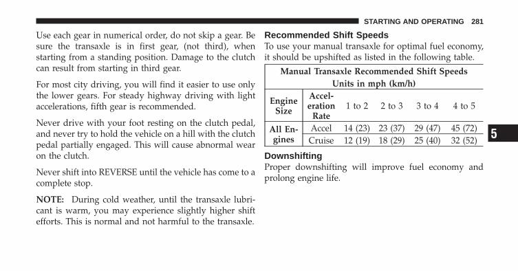
Use each gear in numerical order, do not skip a gear. Besure the transaxle is in first gear, (not third), whenstarting from a standing position. Damage to the clutchcan result from starting in third gear.
For most city driving, you will find it easier to use onlythe lower gears. For steady highway driving with lightaccelerations, fifth gear is recommended.
Never drive with your foot resting on the clutch pedal,and never try to hold the vehicle on a hill with the clutchpedal partially engaged. This will cause abnormal wearon the clutch.
Never shift into REVERSE until the vehicle has come to acomplete stop.
NOTE: During cold weather, until the transaxle lubri-cant is warm, you may experience slightly higher shiftefforts. This is normal and not harmful to the transaxle.
Recommended Shift SpeedsTo use your manual transaxle for optimal fuel economy,it should be upshifted as listed in the following table.
Manual Transaxle Recommended Shift SpeedsUnits in mph (km/h)
EngineSize
Accel-eration
Rate1 to 2 2 to 3 3 to 4 4 to 5
All En-gines
Accel 14 (23) 23 (37) 29 (47) 45 (72)Cruise 12 (19) 18 (29) 25 (40) 32 (52)
DownshiftingProper downshifting will improve fuel economy andprolong engine life.
5
STARTING AND OPERATING 281
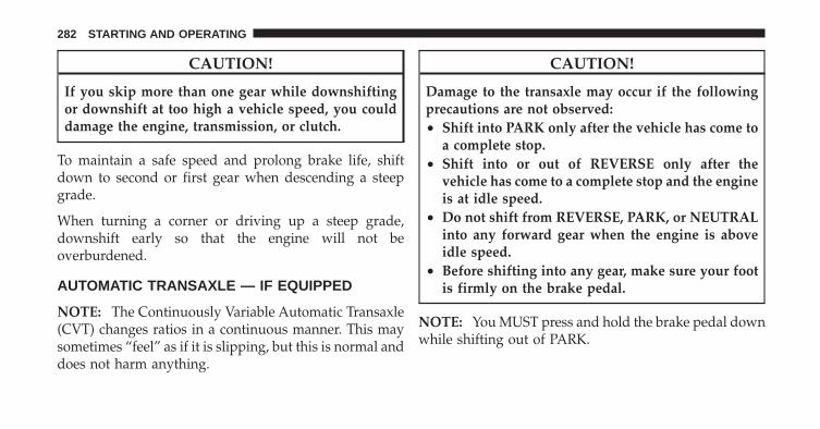
CAUTION!
If you skip more than one gear while downshiftingor downshift at too high a vehicle speed, you coulddamage the engine, transmission, or clutch.
To maintain a safe speed and prolong brake life, shiftdown to second or first gear when descending a steepgrade.
When turning a corner or driving up a steep grade,downshift early so that the engine will not beoverburdened.
AUTOMATIC TRANSAXLE — IF EQUIPPED
NOTE: The Continuously Variable Automatic Transaxle(CVT) changes ratios in a continuous manner. This maysometimes “feel” as if it is slipping, but this is normal anddoes not harm anything.
CAUTION!
Damage to the transaxle may occur if the followingprecautions are not observed:• Shift into PARK only after the vehicle has come to
a complete stop.• Shift into or out of REVERSE only after the
vehicle has come to a complete stop and the engineis at idle speed.
• Do not shift from REVERSE, PARK, or NEUTRALinto any forward gear when the engine is aboveidle speed.
• Before shifting into any gear, make sure your footis firmly on the brake pedal.
NOTE: You MUST press and hold the brake pedal downwhile shifting out of PARK.
282 STARTING AND OPERATING
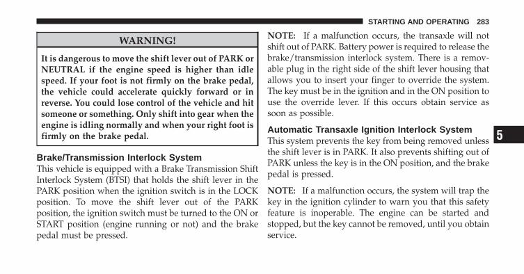
WARNING!
It is dangerous to move the shift lever out of PARK orNEUTRAL if the engine speed is higher than idlespeed. If your foot is not firmly on the brake pedal,the vehicle could accelerate quickly forward or inreverse. You could lose control of the vehicle and hitsomeone or something. Only shift into gear when theengine is idling normally and when your right foot isfirmly on the brake pedal.
Brake/Transmission Interlock SystemThis vehicle is equipped with a Brake Transmission ShiftInterlock System (BTSI) that holds the shift lever in thePARK position when the ignition switch is in the LOCKposition. To move the shift lever out of the PARKposition, the ignition switch must be turned to the ON orSTART position (engine running or not) and the brakepedal must be pressed.
NOTE: If a malfunction occurs, the transaxle will notshift out of PARK. Battery power is required to release thebrake/transmission interlock system. There is a remov-able plug in the right side of the shift lever housing thatallows you to insert your finger to override the system.The key must be in the ignition and in the ON position touse the override lever. If this occurs obtain service assoon as possible.
Automatic Transaxle Ignition Interlock SystemThis system prevents the key from being removed unlessthe shift lever is in PARK. It also prevents shifting out ofPARK unless the key is in the ON position, and the brakepedal is pressed.
NOTE: If a malfunction occurs, the system will trap thekey in the ignition cylinder to warn you that this safetyfeature is inoperable. The engine can be started andstopped, but the key cannot be removed, until you obtainservice.
5
STARTING AND OPERATING 283

Gear RangesDO NOT race the engine when shifting from PARK orNEUTRAL positions into another gear range.
PARKThis range supplements the parking brake by locking thetransmission. The engine can be started in this range.Never use PARK while the vehicle is in motion. Applythe parking brake when leaving the vehicle in this range.Always apply the parking brake first, and then place theshift lever in the PARK position.
WARNING!
Unintended movement of a vehicle could injurethose in and near the vehicle. As with all vehicles,you should never exit a vehicle while the engine isrunning. Before exiting a vehicle, you should alwaysshift the vehicle into PARK, remove the key from theignition, and apply the parking brake. Once the keyis removed from the ignition, the shift lever is lockedin the PARK position, securing the vehicle againstunwanted movement. Furthermore, you should neverleave unattended children inside a vehicle.
The following indicators should be used to ensure thatyou have engaged the shift lever into the PARK position:
• When shifting into PARK, firmly move the shift leverall the way forward until it stops.
284 STARTING AND OPERATING
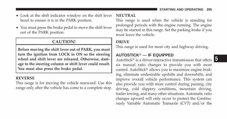
• Look at the shift indicator window on the shift leverbezel to ensure it is in the PARK position.
• You must press the brake pedal to move the shift leverout of the PARK position.
CAUTION!
Before moving the shift lever out of PARK, you mustturn the ignition from LOCK to ON so the steeringwheel and shift lever are released. Otherwise, dam-age to the steering column or shift lever could result.You must also press the brake pedal.
REVERSEThis range is for moving the vehicle rearward. Use thisrange only after the vehicle has come to a complete stop.
NEUTRALThis range is used when the vehicle is standing forprolonged periods with the engine running. The enginemay be started in this range. Set the parking brake if youmust leave the vehicle.
DRIVEThis range is used for most city and highway driving.
AUTOSTICK� — IF EQUIPPEDAutoStick� is a driver-interactive transmission that offerssix manual ratio changes to provide you with morecontrol. AutoStick� allows you to maximize engine brak-ing, eliminate undesirable upshifts and downshifts, andimprove overall vehicle performance. This system canalso provide you with more control during passing, citydriving, cold slippery conditions, mountain driving,trailer towing, and many other situations. Automatic ratiochanges upward will only occur to protect the Continu-ously Variable Automatic Transaxle (CVT) and/or the
5
STARTING AND OPERATING 285

engine from overspeed. Changes down will only happenat minimum engine speed to prevent stalling.
Operation
NOTE: AutoStick� is not functional until the CVTwarms up in cold weather.
AutoStick� operation is activated in the DRIVE positionby moving the shift lever side-to-side. Moving the shiftlever to the (+) side will activate AutoStick� and shift upto the next higher manual ratio, unless you are alreadyoperating in or near Overdrive, in which case sixth gearratio will be selected. In like manner, moving the shiftlever to (-) will activate AutoStick� and shift to the nextlower manual ratio. After AutoStick� is activated, themanual ratio selected is displayed in the transmissionratio display and tipping the shift lever to the (+) or (-)direction will cause an upshift or downshift by one ratio.
AutoStick� is deactivated:
• By holding the shift lever to (+) momentarily
• When the shift lever is shifted out of DRIVE
• When in sixth position, touching the shift lever to theright
• When heavy Anti-Lock Brake System (ABS) applica-tion is detected
General Information
• If a ratio other than first is selected and the vehicle isbrought to a stop, the transaxle control logic willautomatically select the first gear ratio.
• If a low range is selected and the engine accelerates tothe rev limit, the transaxle will automatically select thenext higher ratio.
286 STARTING AND OPERATING

• If a downshift would cause the engine to overspeed,that shift will not occur until it is safe for the engine.However. the CVT will stay in the manually selectedratio.
• If the system detects powertrain overheating, thetransmission will revert to the automatic shift modeand remain in that mode until the powertrain cools off.
• If the system detects a problem, it will disable theAutoStick� mode and the transmission will return tothe automatic mode until the problem is corrected.
FOUR-WHEEL DRIVE OPERATION — IFEQUIPPEDThis feature provides full time, on-demand, four–wheeldrive (4WD).
Where one or more wheels have wheel spin or if addi-tional traction is needed in sand, deep snow, or loosetraction surfaces, activate the “4WD LOCK” switch bypulling up once and releasing. This locks the centercoupling allowing more torque to be sent to the rearwheels. The “4WD Indicator Light” will come on in the
Four-Wheel Drive Switch
5
STARTING AND OPERATING 287

cluster. This can be done on the fly, at any vehicle speed.To deactivate, simply pull on the switch one more time.The “4WD Indicator Light” will then go out.
NOTE: Refer to “Electronic Brake Control System/Electronic Stability Control (ESC)” in “Starting and Op-erating” for further information.
DRIVING ON SLIPPERY SURFACES
AccelerationRapid acceleration on snow covered, wet, or other slip-pery surfaces may cause the front wheels to pull errati-cally to the right or left. This phenomenon occurs whenthere is a difference in the surface traction under the front(driving) wheels.
WARNING!
Rapid acceleration on slippery surfaces is dangerous.Unequal traction can cause sudden pulling of thefront wheels. You could lose control of the vehicleand possibly have an accident. Accelerate slowly andcarefully whenever there is likely to be poor traction(ice, snow, wet, mud, loose sand, etc.).
TractionWhen driving on wet or slushy roads, it is possible for awedge of water to build up between the tire and roadsurface. This is hydroplaning and may cause partial orcomplete loss of vehicle control and stopping ability. Toreduce this possibility, the following precautions shouldbe observed:
1. Slow down during rainstorms or when roads areslushy.
288 STARTING AND OPERATING
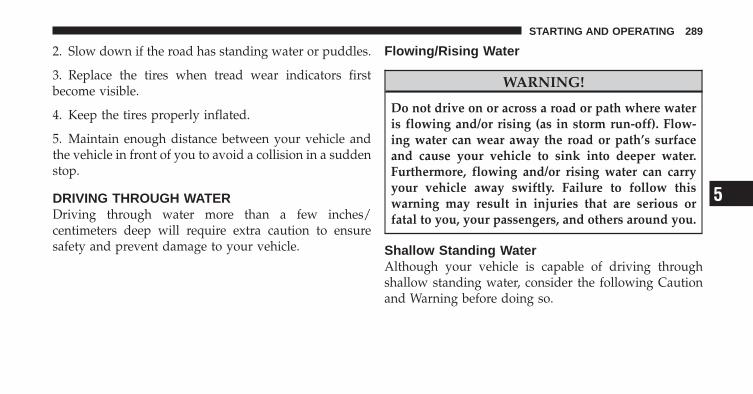
2. Slow down if the road has standing water or puddles.
3. Replace the tires when tread wear indicators firstbecome visible.
4. Keep the tires properly inflated.
5. Maintain enough distance between your vehicle andthe vehicle in front of you to avoid a collision in a suddenstop.
DRIVING THROUGH WATERDriving through water more than a few inches/centimeters deep will require extra caution to ensuresafety and prevent damage to your vehicle.
Flowing/Rising Water
WARNING!
Do not drive on or across a road or path where wateris flowing and/or rising (as in storm run-off). Flow-ing water can wear away the road or path’s surfaceand cause your vehicle to sink into deeper water.Furthermore, flowing and/or rising water can carryyour vehicle away swiftly. Failure to follow thiswarning may result in injuries that are serious orfatal to you, your passengers, and others around you.
Shallow Standing WaterAlthough your vehicle is capable of driving throughshallow standing water, consider the following Cautionand Warning before doing so.
5
STARTING AND OPERATING 289
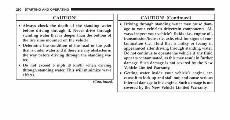
CAUTION!
• Always check the depth of the standing waterbefore driving through it. Never drive throughstanding water that is deeper than the bottom ofthe tire rims mounted on the vehicle.
• Determine the condition of the road or the paththat is under water and if there are any obstacles inthe way before driving through the standing wa-ter.
• Do not exceed 5 mph (8 km/h) when drivingthrough standing water. This will minimize waveeffects.
(Continued)
CAUTION! (Continued)• Driving through standing water may cause dam-
age to your vehicle’s drivetrain components. Al-ways inspect your vehicle’s fluids (i.e., engine oil,transmission/transaxle, axle, etc.) for signs of con-tamination (i.e., fluid that is milky or foamy inappearance) after driving through standing water.Do not continue to operate the vehicle if any fluidappears contaminated, as this may result in furtherdamage. Such damage is not covered by the NewVehicle Limited Warranty.
• Getting water inside your vehicle’s engine cancause it to lock up and stall out, and cause seriousinternal damage to the engine. Such damage is notcovered by the New Vehicle Limited Warranty.
290 STARTING AND OPERATING

WARNING!
• Driving through standing water limits your vehi-cle’s traction capabilities. Do not exceed 5 mph(8 km/h) when driving through standing water.
• Driving through standing water limits your vehi-cle’s braking capabilities, which increases stop-ping distances. Therefore, after driving throughstanding water, drive slowly and lightly press onthe brake pedal several times to dry the brakes.
• Getting water inside your vehicle’s engine cancause it to lock up and stall out, and leave youstranded.
• Failure to follow these warnings may result ininjuries that are serious or fatal to you, yourpassengers, and others around you.
ON-ROAD DRIVING TIPSUtility vehicles have higher ground clearance and anarrower track to make them capable of performing in awide variety of off-road applications. Specific designcharacteristics give them a higher center of gravity thanordinary cars.
An advantage of the higher ground clearance is a betterview of the road, allowing you to anticipate problems.They are not designed for cornering at the same speeds asconventional two-wheel drive vehicles any more thanlow-slung sports cars are designed to perform satisfacto-rily in off-road conditions. If at all possible, avoid sharpturns or abrupt maneuvers. As with other vehicles of thistype, failure to operate this vehicle correctly may result inloss of control or vehicle rollover.
POWER STEERINGThe standard power steering system will give you goodvehicle response and increased ease of maneuverability
5
STARTING AND OPERATING 291

in tight spaces. The system will provide mechanicalsteering capability if power assist is lost.
If for some reason the power assist is interrupted, it willstill be possible to steer your vehicle. Under these condi-tions, you will observe a substantial increase in steeringeffort, especially at very low vehicle speeds and duringparking maneuvers.
NOTE:• Increased noise levels at the end of the steering wheel
travel are considered normal and do not indicate thatthere is a problem with the power steering system.
• Upon initial start-up in cold weather, the power steer-ing pump may make noise for a short amount of time.This is due to the cold, thick fluid in the steeringsystem. This noise should be considered normal, and itdoes not in any way damage the steering system.
WARNING!
Continued operation with reduced power steeringassist could pose a safety risk to yourself and others.Service should be obtained as soon as possible.
CAUTION!
Prolonged operation of the steering system at the endof the steering wheel travel will increase the steeringfluid temperature and it should be avoided whenpossible. Damage to the power steering pump mayoccur.
292 STARTING AND OPERATING
Power Steering Fluid CheckChecking the power steering fluid level at a definedservice interval is not required. The fluid should only bechecked if a leak is suspected, abnormal noises areapparent, and/or the system is not functioning as antici-pated. Coordinate inspection efforts through an autho-rized dealer.
CAUTION!
Do not use chemical flushes in your power steeringsystem as the chemicals can damage your powersteering components. Such damage is not covered bythe New Vehicle Limited Warranty.
WARNING!
Fluid level should be checked on a level surface andwith the engine off to prevent injury from movingparts and to ensure accurate fluid level reading. Donot overfill. Use only manufacturer’s recommendedpower steering fluid.
If necessary, add fluid to restore to the proper indicatedlevel. With a clean cloth, wipe any spilled fluid from allsurfaces. Refer to “Fluids, Lubricants, and GenuineParts” in “Maintaining Your Vehicle” for furtherinformation.
PARKING BRAKEBefore leaving the vehicle, make sure that the parkingbrake is fully applied. Also, be certain to leave anautomatic transaxle in PARK, or manual transaxle inREVERSE or first gear.
5
STARTING AND OPERATING 293
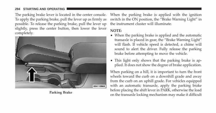
The parking brake lever is located in the center console.To apply the parking brake, pull the lever up as firmly aspossible. To release the parking brake, pull the lever upslightly, press the center button, then lower the levercompletely.
When the parking brake is applied with the ignitionswitch in the ON position, the “Brake Warning Light” inthe instrument cluster will illuminate.
NOTE:• When the parking brake is applied and the automatic
transaxle is placed in gear, the “Brake Warning Light”will flash. If vehicle speed is detected, a chime willsound to alert the driver. Fully release the parkingbrake before attempting to move the vehicle.
• This light only shows that the parking brake is ap-plied. It does not show the degree of brake application.
When parking on a hill, it is important to turn the frontwheels toward the curb on a downhill grade and awayfrom the curb on an uphill grade. For vehicles equippedwith an automatic transaxle, apply the parking brakebefore placing the shift lever in PARK, otherwise the loadon the transaxle locking mechanism may make it difficult
Parking Brake
294 STARTING AND OPERATING
to move the shift lever out of PARK. The parking brakeshould always be applied whenever the driver is not inthe vehicle.
WARNING!
• Never leave children alone in a vehicle. Leavingunattended children in a vehicle is dangerous for anumber of reasons. A child or others could beseriously or fatally injured.
• Do not leave the key in the ignition switch. A childcould operate power windows, other controls, ormove the vehicle.
• Be sure the parking brake is fully disengagedbefore driving; failure to do so can lead to brakefailure and an accident.
(Continued)
WARNING! (Continued)• Always fully apply the parking brake when leav-
ing your vehicle or it may roll and cause damage orinjury. Also, be certain to leave an automatictransaxle in PARK, a manual transaxle in RE-VERSE or first gear. Failure to do so may cause thevehicle to roll and cause damage or injury.
CAUTION!
If the Brake System Warning Light remains on withthe parking brake released, a brake system malfunc-tion is indicated. Have the brake system serviced byan authorized dealer immediately.
5
STARTING AND OPERATING 295
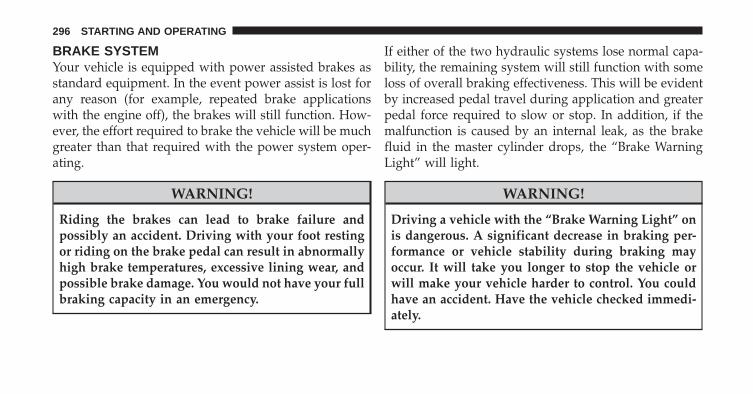
BRAKE SYSTEMYour vehicle is equipped with power assisted brakes asstandard equipment. In the event power assist is lost forany reason (for example, repeated brake applicationswith the engine off), the brakes will still function. How-ever, the effort required to brake the vehicle will be muchgreater than that required with the power system oper-ating.
WARNING!
Riding the brakes can lead to brake failure andpossibly an accident. Driving with your foot restingor riding on the brake pedal can result in abnormallyhigh brake temperatures, excessive lining wear, andpossible brake damage. You would not have your fullbraking capacity in an emergency.
If either of the two hydraulic systems lose normal capa-bility, the remaining system will still function with someloss of overall braking effectiveness. This will be evidentby increased pedal travel during application and greaterpedal force required to slow or stop. In addition, if themalfunction is caused by an internal leak, as the brakefluid in the master cylinder drops, the “Brake WarningLight” will light.
WARNING!
Driving a vehicle with the “Brake Warning Light” onis dangerous. A significant decrease in braking per-formance or vehicle stability during braking mayoccur. It will take you longer to stop the vehicle orwill make your vehicle harder to control. You couldhave an accident. Have the vehicle checked immedi-ately.
296 STARTING AND OPERATING
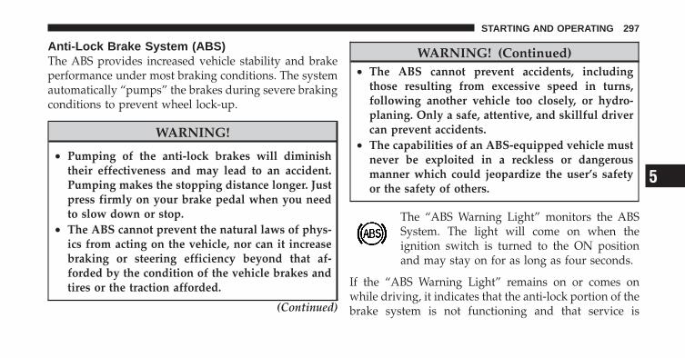
Anti-Lock Brake System (ABS)The ABS provides increased vehicle stability and brakeperformance under most braking conditions. The systemautomatically “pumps” the brakes during severe brakingconditions to prevent wheel lock-up.
WARNING!
• Pumping of the anti-lock brakes will diminishtheir effectiveness and may lead to an accident.Pumping makes the stopping distance longer. Justpress firmly on your brake pedal when you needto slow down or stop.
• The ABS cannot prevent the natural laws of phys-ics from acting on the vehicle, nor can it increasebraking or steering efficiency beyond that af-forded by the condition of the vehicle brakes andtires or the traction afforded.
(Continued)
WARNING! (Continued)• The ABS cannot prevent accidents, including
those resulting from excessive speed in turns,following another vehicle too closely, or hydro-planing. Only a safe, attentive, and skillful drivercan prevent accidents.
• The capabilities of an ABS-equipped vehicle mustnever be exploited in a reckless or dangerousmanner which could jeopardize the user’s safetyor the safety of others.
The “ABS Warning Light” monitors the ABSSystem. The light will come on when theignition switch is turned to the ON positionand may stay on for as long as four seconds.
If the “ABS Warning Light” remains on or comes onwhile driving, it indicates that the anti-lock portion of thebrake system is not functioning and that service is
5
STARTING AND OPERATING 297
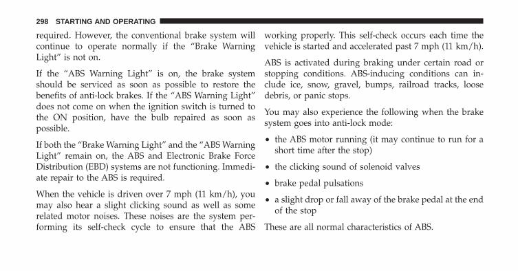
required. However, the conventional brake system willcontinue to operate normally if the “Brake WarningLight” is not on.
If the “ABS Warning Light” is on, the brake systemshould be serviced as soon as possible to restore thebenefits of anti-lock brakes. If the “ABS Warning Light”does not come on when the ignition switch is turned tothe ON position, have the bulb repaired as soon aspossible.
If both the “Brake Warning Light” and the “ABS WarningLight” remain on, the ABS and Electronic Brake ForceDistribution (EBD) systems are not functioning. Immedi-ate repair to the ABS is required.
When the vehicle is driven over 7 mph (11 km/h), youmay also hear a slight clicking sound as well as somerelated motor noises. These noises are the system per-forming its self-check cycle to ensure that the ABS
working properly. This self-check occurs each time thevehicle is started and accelerated past 7 mph (11 km/h).
ABS is activated during braking under certain road orstopping conditions. ABS-inducing conditions can in-clude ice, snow, gravel, bumps, railroad tracks, loosedebris, or panic stops.
You may also experience the following when the brakesystem goes into anti-lock mode:
• the ABS motor running (it may continue to run for ashort time after the stop)
• the clicking sound of solenoid valves
• brake pedal pulsations
• a slight drop or fall away of the brake pedal at the endof the stop
These are all normal characteristics of ABS.
298 STARTING AND OPERATING

WARNING!
The Anti-Lock Brake System (ABS) contains sophis-ticated electronic equipment that may be susceptibleto interference caused by improperly installed orhigh output radio transmitting equipment. This in-terference can cause possible loss of Anti-Lock brak-ing capability. Installation of such equipment shouldbe performed by qualified professionals.
All vehicle wheels and tires must be the same size andtype and tires must be properly inflated to produceaccurate signals for the computer.
ELECTRONIC BRAKE CONTROL SYSTEMYour vehicle may be equipped with an optional ad-vanced electronic brake control system that includesAnti-Lock Brake System (ABS), Traction Control System
(TCS), Brake Assist System (BAS), Electronic Roll Mitiga-tion (ERM), Hill Start Assist (HSA), and Electronic Sta-bility Control (ESC). All systems work together to en-hance vehicle stability and control in various drivingconditions and are commonly referred to as ESC.
Anti-Lock Brake System (ABS)This system aids the driver in maintaining vehicle controlunder adverse braking conditions. The system controlshydraulic brake pressure to prevent wheel lockup andhelp avoid skidding on slippery surfaces during braking.Refer to “Anti-Lock Brake System” in “Starting andOperating” for further information.
Traction Control System (TCS)This system monitors the amount of wheel spin of each ofthe driven wheels. If wheel spin is detected, brake pres-sure is applied to the slipping wheel(s) and engine poweris reduced to provide enhanced acceleration and stability.A feature of the TCS system functions similar to a limited
5
STARTING AND OPERATING 299

slip differential and controls the wheel spin across adriven axle. If one wheel on a driven axle is spinningfaster than the other, the system will apply the brake ofthe spinning wheel. This will allow more engine torque tobe applied to the wheel that is not spinning. This featureremains active even if TCS and ESC are in either the“Partial Off” or “Full Off” modes. Refer to “ElectronicStability Control (ESC)” in this section of this manual.
Brake Assist System (BAS)The BAS is designed to optimize the vehicle’s brakingcapability during emergency braking maneuvers. Thesystem detects an emergency braking situation by sens-ing the rate and amount of brake application and thenapplies optimum pressure to the brakes. This can helpreduce braking distances. The BAS complements theAnti-Lock Brake System (ABS). Applying the brakes veryquickly results in the best BAS assistance. To receive thebenefit of the system, you must apply continuous brak-ing pressure during the stopping sequence (do not
“pump” the brakes). Do not reduce brake pedal pressureunless braking is no longer desired. Once the brake pedalis released, the BAS is deactivated.
WARNING!
• The Brake Assist System (BAS) cannot prevent thenatural laws of physics from acting on the vehicle,nor can it increase the traction afforded by prevail-ing road conditions.
• The BAS cannot prevent accidents, includingthose resulting from excessive speed in turns,driving on very slippery surfaces, or hydroplan-ing. Only a safe, attentive, and skillful driver canprevent accidents.
• The capabilities of a BAS-equipped vehicle mustnever be exploited in a reckless or dangerousmanner which could jeopardize the user’s safetyor the safety of others.
300 STARTING AND OPERATING

Electronic Roll Mitigation (ERM)This system anticipates the potential for wheel lift bymonitoring the driver’s steering wheel input and thespeed of the vehicle. When ERM determines that the rateof change of the steering wheel angle and vehicles speedare sufficient to potentially cause wheel lift, it applies thebrake of the appropriate wheel and may also reduceengine power to lessen the chance that wheel lift willoccur. ERM will only intervene during very severe orevasive driving maneuvers.
ERM can only reduce the chance of wheel lift occurringduring severe or evasive driving maneuvers. It can notprevent wheel lift due to other factors such as roadconditions, leaving the roadway or striking objects orother vehicles.
NOTE: Anytime the ESC system is in the “Full Off”mode, ERM is disabled. Refer to “Electronic StabilityControl (ESC)” in this section for a complete explanationof the available ESC modes.
WARNING!
Many factors, such as vehicle loading, road condi-tions and driving conditions, influence the chancethat wheel lift or rollover may occur. ERM cannotprevent all wheel lift or roll overs, especially thosethat involve leaving the roadway or striking objectsor other vehicles. Only a safe, attentive, and skillfuldriver can prevent accidents. The capabilities of anERM-equipped vehicle must never be exploited in areckless or dangerous manner which could jeopar-dize the user’s safety or the safety of others.
5
STARTING AND OPERATING 301

Hill Start Assist (HSA) – Manual Transaxle OnlyThe HSA system is designed to assist the driver whenstarting a vehicle from a stop on a hill. HSA will maintainthe level of brake pressure the driver applied for a shortperiod of time after the driver takes their foot off of thebrake pedal. If the driver does not apply the throttleduring this short period of time, the system will releasebrake pressure and the vehicle will roll down the hill. Thesystem will release brake pressure in proportion toamount of throttle applied as the vehicle starts to move inthe intended direction of travel.
HSA Activation CriteriaThe following criteria must be met in order for HSA toactivate:
• Vehicle must be stopped.
• Vehicle must be on a 7% grade or greater hill.
• Gear selection matches vehicle uphill direction (i.e.,vehicle facing uphill is in forward gear; vehicle back-ing uphill is in REVERSE gear).
WARNING!
There may be situations on minor hills (i.e., less than8%), with a loaded vehicle, or while pulling a trailer,when the system will not activate and slight rollingmay occur. This could cause a collision with anothervehicle or object. Always remember the driver isresponsible for braking the vehicle.
Disabling/Enabling HSAIf you wish to turn on or off the HSA system, it can bedone using the Customer Programmable Features in theElectronic Vehicle Information Center (EVIC). Refer to“Electronic Vehicle Information Center (EVIC)” in “Un-derstanding Your Instrument Panel” for further informa-tion.
302 STARTING AND OPERATING

For vehicles not equipped with the EVIC, perform thefollowing steps:
NOTE: You must complete Steps 1 through 8 within90 seconds.
1. Center the steering wheel (front wheels pointingstraight forward).
2. Shift the transaxle into NEUTRAL.
3. Apply the parking brake.
4. Start the engine.
5. Release the clutch pedal.
6. Rotate the steering wheel one-half turn to the left.
7. Press the “ESC Off” switch (located in the lowerswitch bank below the climate controls) four times within20 seconds. The “ESC Off Indicator Light” should turn onand turn off two times.
8. Rotate the steering wheel back to center and then anadditional half-turn to the right.
9. Turn the ignition switch to the OFF position and thenback to the ON position. If the sequence was completedproperly, the “ESC Off Indicator Light” will blink severaltimes to confirm HSA is disabled.
10. Repeat these steps if you want to return this featureto it’s previous setting.
Electronic Stability Control (ESC)
This system enhances directional control and stability ofthe vehicle under various driving conditions. ESC cor-rects for over-steering or under-steering of the vehicle byapplying the brake of the appropriate wheel to assist incounteracting the over-steering or under-steering condi-tion. Engine power may also be reduced to help thevehicle maintain the desired path. ESC uses sensors inthe vehicle to determine the vehicle path intended by the
5
STARTING AND OPERATING 303
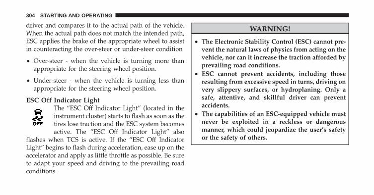
driver and compares it to the actual path of the vehicle.When the actual path does not match the intended path,ESC applies the brake of the appropriate wheel to assistin counteracting the over-steer or under-steer condition
• Over-steer - when the vehicle is turning more thanappropriate for the steering wheel position.
• Under-steer - when the vehicle is turning less thanappropriate for the steering wheel position.
ESC Off Indicator LightThe “ESC Off Indicator Light” (located in theinstrument cluster) starts to flash as soon as thetires lose traction and the ESC system becomesactive. The “ESC Off Indicator Light” also
flashes when TCS is active. If the “ESC Off IndicatorLight” begins to flash during acceleration, ease up on theaccelerator and apply as little throttle as possible. Be sureto adapt your speed and driving to the prevailing roadconditions.
WARNING!
• The Electronic Stability Control (ESC) cannot pre-vent the natural laws of physics from acting on thevehicle, nor can it increase the traction afforded byprevailing road conditions.
• ESC cannot prevent accidents, including thoseresulting from excessive speed in turns, driving onvery slippery surfaces, or hydroplaning. Only asafe, attentive, and skillful driver can preventaccidents.
• The capabilities of an ESC-equipped vehicle mustnever be exploited in a reckless or dangerousmanner, which could jeopardize the user’s safetyor the safety of others.
304 STARTING AND OPERATING
ESC Malfunction Indicator LightThe “ESC Malfunction Indicator Light” in theinstrument cluster will come on when theignition switch is turned to the ON position. Itshould go out with the engine running. If the
“ESC Malfunction Indicator Light” comes on continu-ously with the engine running, a malfunction has beendetected in the ESC system. If this light remains on afterseveral ignition cycles, and the vehicle has been drivenseveral miles (kilometers) at speeds greater than 30 mph(48 km/h), see your authorized dealer as soon as possibleto have the problem diagnosed and corrected.
NOTE:• The “ESC Off Indicator Light” and the “ESC Malfunc-
tion Indicator Light” come on momentarily each timethe ignition switch is turned ON.
• Each time the ignition is turned ON, the ESC systemwill be ON even if it was turned off previously.
• The ESC system will make buzzing or clicking soundswhen it is active. This is normal; the sounds will stopwhen ESC becomes inactive following the maneuverthat caused the ESC activation.
ESC Operating ModesThe ESC system has three available operating modes forfour–wheel drive equipped vehicles and two availableoperating modes for two–wheel drive equipped vehicles.
Full On (Four-Wheel Drive Models) or On (Two-WheelDrive Models)This is the normal operating mode for ESC. Wheneverthe vehicle is started the ESC system will be in this “On”mode. This mode should be used for most drivingsituations. ESC should only be turned to “Partial Off” or“ESC Off” for specific reasons as noted below.
5
STARTING AND OPERATING 305
Partial Off (Four-Wheel Drive Models) or On(Two-Wheel Drive Models)This mode is entered by momentarily pressing the “ESCOff” switch. When in “Partial Off” mode, the TCS portionof ESC, except for the “limited slip” feature described inthe TCS section, has been disabled and the “ESP/TCSIndicator Light” will be illuminated. All other stabilityfeatures of ESC function normally. This mode is intendedto be used if the vehicle is in deep snow, sand or gravelconditions and more wheel spin than ESC would nor-mally allow is required to gain traction.
To turn ESC on again, momentarily press the “ESC Off”switch. This will restore the normal “ESC On” mode ofoperation.
NOTE: To improve the vehicle’s traction when drivingwith snow chains, or starting off in deep snow, sand orgravel, it may be desirable to switch to the “Partial Off”
mode by pressing the “ESC Off” switch. Once the situa-tion requiring ESC to be switched to the “Partial Off”mode is overcome, turn ESC back on by momentarilypressing the “ESC Off” switch. This may be done whilethe vehicle is in motion.
Full Off (Four-Wheel Drive Models Only)This mode is intended for off-highway or off-road usewhen ESC stability features could inhibit vehicle maneu-verability due to trail conditions. This mode is entered bypressing and holding the “ESC Off” switch for fiveseconds when the vehicle is stopped and the engine isrunning. After five seconds, the “ESP/TCS IndicatorLight” will illuminate and the “ESC OFF” message willappear in the odometer. Press and release the TripOdometer button located on the instrument cluster toclear this message.
In this mode, ESC and TCS, except for the “limited slip”feature described in the TCS section, are turned off until
306 STARTING AND OPERATING

the vehicle reaches a speed of 35 mph (56 km/h). At35 mph (56 km/h) the system returns to “Partial Off”mode, as described above. TCS remains off. When thevehicle speed drops below 30 mph (48 km/h) the ESCsystem shuts off. ESC is deactivated at low vehicle speedsso that it will not interfere with off-road driving however,ESC function returns to provide the stability feature atspeeds above 35 mph (56 km/h). The “ESP/TCS Indica-tor Light” will always be illuminated when ESC is off.
To turn ESC on again, momentarily press the “ESC Off”switch. This will restore the “ESC On” mode of operation.
NOTE: The “ESC OFF” message will display and anaudible chime will sound when the shift lever is placedinto the PARK position from any other position, and thenmoved out of the PARK position. This will occur even ifthe message was previously cleared.
WARNING!
With the ESC switched off, the enhanced vehiclestability offered by ESC is unavailable. In an emer-gency evasive maneuver, the ESC system will notengage to assist in maintaining stability. “ESC Off”mode is intended for off-highway or off-road useonly.
5
STARTING AND OPERATING 307

TIRE SAFETY INFORMATION
Tire Markings
NOTE:• P (Passenger) - Metric tire sizing is based on U.S.
design standards. P-Metric tires have the letter “P”molded into the sidewall preceding the size designa-tion. Example: P215/65R15 95H.
• European-Metric tire sizing is based on Europeandesign standards. Tires designed to this standard havethe tire size molded into the sidewall beginning withthe section width. The letter �P� is absent from this tiresize designation. Example: 215/65R15 96H.
• LT (Light Truck) - Metric tire sizing is based on U.S.design standards. The size designation for LT-Metrictires is the same as for P-Metric tires except for theletters “LT” that are molded into the sidewall preced-ing the size designation. Example: LT235/85R16.
• Temporary spare tires are high-pressure compactspares designed for temporary emergency use only.
1 — U.S. DOT Safety Stan-dards Code (TIN)
4 — Maximum Load
2 — Size Designation 5 — Maximum Pressure3 — Service Description 6 — Treadwear, Traction and
Temperature Grades
308 STARTING AND OPERATING

Tires designed to this standard have the letter “T”molded into the sidewall preceding the size designa-tion. Example: T145/80D18 103M.
• High flotation tire sizing is based on U.S. designstandards and it begins with the tire diameter moldedinto the sidewall. Example: 31x10.5 R15 LT.
Tire Sizing Chart
EXAMPLE:Size Designation:
P = Passenger car tire size based on U.S. design standards�....blank....� = Passenger car tire based on European design standardsLT = Light truck tire based on U.S. design standardsT = Temporary spare tire31 = Overall diameter in inches (in)215 = Section width in millimeters (mm)65 = Aspect ratio in percent (%)
— Ratio of section height to section width of tire10.5 = Section width in inches (in)R = Construction code
— �R� means radial construction—�D� means diagonal or bias construction
15 = Rim diameter in inches (in)
5
STARTING AND OPERATING 309

EXAMPLE:Service Description:
95 = Load Index— A numerical code associated with the maximum load a tire can carry
H = Speed Symbol— A symbol indicating the range of speeds at which a tire can carry a load correspondingto its load index under certain operating conditions— The maximum speed corresponding to the speed symbol should only be achieved underspecified operating conditions (i.e., tire pressure, vehicle loading, road conditions, andposted speed limits)
Load Identification:�....blank....� = Absence of any text on the sidewall of the tire indicates a Standard Load (SL) tireExtra Load (XL) = Extra load (or reinforced) tireLight Load = Light load tireC, D, E = Load range associated with the maximum load a tire can carry at a specified pressure
Maximum Load — Maximum load indicates the maximum load this tire is designed to carryMaximum Pressure — Maximum pressure indicates the maximum permissible cold tire inflation pressure forthis tire
310 STARTING AND OPERATING
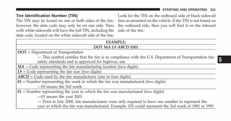
Tire Identification Number (TIN)The TIN may be found on one or both sides of the tire,however, the date code may only be on one side. Tireswith white sidewalls will have the full TIN, including thedate code, located on the white sidewall side of the tire.
Look for the TIN on the outboard side of black sidewalltires as mounted on the vehicle. If the TIN is not found onthe outboard side, then you will find it on the inboardside of the tire.
EXAMPLE:DOT MA L9 ABCD 0301
DOT = Department of Transportation— This symbol certifies that the tire is in compliance with the U.S. Department of Transportation tiresafety standards and is approved for highway use
MA = Code representing the tire manufacturing location (two digits)L9 = Code representing the tire size (two digits)ABCD = Code used by the tire manufacturer (one to four digits)03 = Number representing the week in which the tire was manufactured (two digits)
—03 means the 3rd week.01 = Number representing the year in which the tire was manufactured (two digits)
—01 means the year 2001— Prior to July 2000, tire manufacturers were only required to have one number to represent theyear in which the tire was manufactured. Example: 031 could represent the 3rd week of 1981 or 1991
5
STARTING AND OPERATING 311
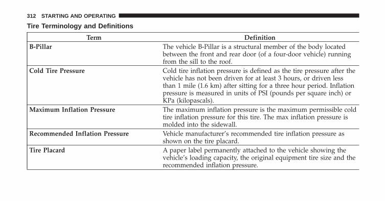
Tire Terminology and Definitions
Term DefinitionB-Pillar The vehicle B-Pillar is a structural member of the body located
between the front and rear door (of a four-door vehicle) runningfrom the sill to the roof.
Cold Tire Pressure Cold tire inflation pressure is defined as the tire pressure after thevehicle has not been driven for at least 3 hours, or driven lessthan 1 mile (1.6 km) after sitting for a three hour period. Inflationpressure is measured in units of PSI (pounds per square inch) orKPa (kilopascals).
Maximum Inflation Pressure The maximum inflation pressure is the maximum permissible coldtire inflation pressure for this tire. The max inflation pressure ismolded into the sidewall.
Recommended Inflation Pressure Vehicle manufacturer’s recommended tire inflation pressure asshown on the tire placard.
Tire Placard A paper label permanently attached to the vehicle showing thevehicle’s loading capacity, the original equipment tire size and therecommended inflation pressure.
312 STARTING AND OPERATING
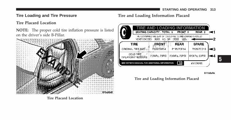
Tire Loading and Tire Pressure
Tire Placard Location
NOTE: The proper cold tire inflation pressure is listedon the driver’s side B-Pillar.
Tire and Loading Information Placard
Tire Placard Location
Tire and Loading Information Placard
5
STARTING AND OPERATING 313

This placard tells you important information aboutthe:1) number of people that can be carried in the vehicle2) total weight your vehicle can carry3) tire size designed for your vehicle4) cold tire inflation pressures for the front, rear, andspare tires.
LoadingThe vehicle maximum load on the tire must not exceedthe load carrying capacity of the tire on your vehicle. Youwill not exceed the tire’s load carrying capacity if youadhere to the loading conditions, tire size, and cold tireinflation pressures specified on the Tire and LoadingInformation placard and in the “Vehicle Loading” sectionof this manual.
NOTE: Under a maximum loaded vehicle condition,gross axle weight ratings (GAWRs) for the front and rear
axles must not be exceeded. For further information onGAWRs, vehicle loading, and trailer towing, refer to“Vehicle Loading” in this section.
To determine the maximum loading conditions of yourvehicle, locate the statement “The combined weight ofoccupants and cargo should never exceed XXX lbs orXXX kg” on the Tire and Loading Information placard.The combined weight of occupants, cargo/luggage andtrailer tongue weight (if applicable) should never exceedthe weight referenced here.
Steps for Determining Correct Load Limit
1. Locate the statement “The combined weight of occu-pants and cargo should never exceed XXX lbs or XXX kg”on your vehicle’s placard.
2. Determine the combined weight of the driver andpassengers that will be riding in your vehicle.
314 STARTING AND OPERATING

3. Subtract the combined weight of the driver and pas-sengers from XXX lbs or XXX kg.
4. The resulting figure equals the available amount ofcargo and luggage load capacity. For example, if “XXX”amount equals 1,400 lbs (635 kg) and there will be five150 lb (68 kg) passengers in your vehicle, the amount ofavailable cargo and luggage load capacity is 650 lbs(295 kg) (since 5 x 150 = 750, and 1400 – 750 = 650 lbs[295 kg]).
5. Determine the combined weight of luggage and cargobeing loaded on the vehicle. That weight may not safelyexceed the available cargo and luggage load capacitycalculated in Step 4.
6. If your vehicle will be towing a trailer, load from yourtrailer will be transferred to your vehicle. Consult thismanual to determine how this reduces the availablecargo and luggage load capacity of your vehicle.
NOTE:• The following table shows examples on how to calcu-
late total load, cargo/luggage, and towing capacitiesof your vehicle with varying seating configurationsand number and size of occupants. This table is forillustration purposes only and may not be accurate forthe seating and load carry capacity of your vehicle.
• For the following example, the combined weight ofoccupants and cargo should never exceed 865 lbs(392 kg). 5
STARTING AND OPERATING 315

316 STARTING AND OPERATING

WARNING!
Overloading of your tires is dangerous. Overloadingcan cause tire failure, affect vehicle handling, andincrease your stopping distance. Use tires of therecommended load capacity for your vehicle. Neveroverload them.
TIRES — GENERAL INFORMATION
Tire PressureProper tire inflation pressure is essential to the safe andsatisfactory operation of your vehicle. Three primaryareas are affected by improper tire pressure:
Safety
WARNING!
• Improperly inflated tires are dangerous and cancause accidents.
• Under-inflation increases tire flexing and can re-sult in over-heating and tire failure.
• Over-inflation reduces a tire’s ability to cushionshock. Objects on the road and chuckholes cancause damage that result in tire failure.
• Unequal tire pressures can cause steering prob-lems. You could lose control of your vehicle.
• Over-inflated or under-inflated tires can affectvehicle handling and can fail suddenly, resultingin loss of vehicle control.
(Continued)
5
STARTING AND OPERATING 317

WARNING! (Continued)• Unequal tire pressures from one side of the ve-
hicle to the other can cause the vehicle to drift tothe right or left.
• Always drive with each tire inflated to the recom-mended cold tire inflation pressure.
EconomyImproper inflation pressures can cause uneven wearpatterns to develop across the tire tread. These abnormalwear patterns will reduce tread life resulting in a need forearlier tire replacement. Under-inflation also increases tirerolling resistance and results in higher fuel consumption.
Ride Comfort and Vehicle StabilityProper tire inflation contributes to a comfortable ride.Over-inflation produces a jarring and uncomfortableride.
Tire Inflation PressuresThe proper cold tire inflation pressure is listed on thedriver’s side “B” Pillar.
Some vehicles may have Supplemental Tire PressureInformation for vehicle loads that are less than themaximum loaded vehicle condition. These pressure con-ditions will be found in the “Supplemental Tire PressureInformation” section of this manual.
The pressure should be checked and adjusted as well asinspecting for signs of tire wear or visible damage at leastonce a month. Use a good quality pocket-type gauge tocheck tire pressure. Do not make a visual judgementwhen determining proper inflation. Radial tires may lookproperly inflated even when they are under-inflated.
318 STARTING AND OPERATING

CAUTION!
After inspecting or adjusting the tire pressure, al-ways reinstall the valve stem cap. This will preventmoisture and dirt from entering the valve stem,which could damage the valve stem.
Inflation pressures specified on the placard are always“cold tire inflation pressure.” Cold tire inflation pressureis defined as the tire pressure after the vehicle has notbeen driven for at least three hours or driven less than1 mile (1.6 km) after a three hour period. The cold tireinflation pressure must not exceed the maximum infla-tion pressure molded into the tire sidewall.
Check tire pressures more often if subject to a wide rangeof outdoor temperatures as tire pressures vary withtemperature changes.
Tire pressures change by approximately 1 psi (7 kPa) per12°F (7°C) of air temperature change. Keep this in mindwhen checking tire pressure inside a garage, especially inthe Winter.
Example: If garage temperature = 68°F (20°C) and theoutside temperature = 32°F (0°C) then the cold tireinflation pressure should be increased by 3 psi (21 kPa),which equals 1 psi (7 kPa) for every 12°F (7°C) for thisoutside temperature condition.
Tire pressure may increase from 2 to 6 psi (13 to 40 kPa)during operation. Do not reduce this normal pressurebuild up or your tire pressure will be too low.
Tire Pressures for High Speed OperationThe manufacturer advocates driving at safe speedswithin posted speed limits. Where speed limits or condi-tions are such that the vehicle can be driven at highspeeds, maintaining correct tire inflation pressure is veryimportant. Increased tire pressure and reduced vehicle
5
STARTING AND OPERATING 319
loading may be required for high-speed vehicle opera-tion. Refer to original equipment or an authorized tiredealer for recommended safe operating speeds, loadingand cold tire inflation pressures.
WARNING!
High speed driving with your vehicle under maxi-mum load is dangerous. The added strain on yourtires could cause them to fail. You could have aserious accident. Do not drive a vehicle loaded to themaximum capacity at continuous speeds above75 mph (120 km/h).
Radial Ply Tires
WARNING!
Combining radial ply tires with other types of tireson your vehicle will cause your vehicle to handlepoorly. The instability could cause an accident. Al-ways use radial ply tires in sets of four. Nevercombine them with other types of tires.
Cuts and punctures in radial tires are repairable only inthe tread area because of sidewall flexing. Consult yourauthorized tire dealer for radial tire repairs.
Compact Spare Tire – If EquippedThe compact spare is for temporary emergency use withradial tires. It is engineered to be used on your stylevehicle only. Since this tire has limited tread life, theoriginal tire should be repaired (or replaced) and rein-stalled at the first opportunity.
320 STARTING AND OPERATING
WARNING!
• Temporary use spare tires are for emergency useonly. With these tires, do not drive more than50 mph (80 km/h).
• Temporary use spare tires have limited tread life.When the tread is worn to the tread wear indica-tors, the temporary use spare tire needs to bereplaced.
• Be sure to follow the warnings which apply toyour spare. Failure to do so could result in sparetire failure and loss of vehicle control.
Do not install a wheel cover or attempt to mount aconventional tire on the compact spare wheel, since thewheel is designed specifically for the compact spare.
Do not install more than one compact spare tire/wheelon the vehicle at any given time.
CAUTION!
Because of the reduced ground clearance, do not takeyour vehicle through an automatic car wash with thecompact spare installed. Damage to the vehicle mayresult.
Tire SpinningWhen stuck in mud, sand, snow, or ice conditions, do notspin your vehicle’s wheels faster than 30 mph (48 km/h)or for longer than 30 seconds continuously withoutstopping when you are stuck.
Refer to “Freeing A Stuck Vehicle” in “What To Do InEmergencies” for further information.
5
STARTING AND OPERATING 321

WARNING!
Fast spinning tires can be dangerous. Forces gener-ated by excessive wheel speeds may cause tire dam-age or failure. A tire could explode and injure some-one. Do not spin your vehicle’s wheels faster than30 mph (48 km/h) or for more than 30 secondscontinuously when you are stuck, and do not letanyone near a spinning wheel, no matter what thespeed.
Tread Wear IndicatorsTread wear indicators are in the original equipment tiresto help you in determining when your tires should bereplaced. These indicators are molded into the bottom of the tread
grooves. They will appear as bands when the tread depthbecomes 1/16 in (2 mm). When the tread is worn to thetread wear indicators, the tire should be replaced.
1 — Worn Tire2 — New Tire
322 STARTING AND OPERATING
Life of TireThe service life of a tire is dependent upon varyingfactors including, but not limited to:
• Driving style
• Tire pressure
• Distance driven
WARNING!
Tires and the spare tire should be replaced after sixyears, regardless of the remaining tread. Failure tofollow this warning can result in sudden tire failure.You could lose control and have an accident resultingin serious injury or death.
Keep dismounted tires in a cool, dry place with as littleexposure to light as possible. Protect tires from contactwith oil, grease, and gasoline.
Replacement TiresThe tires on your new vehicle provide a balance of manycharacteristics. They should be inspected regularly forwear and correct cold tire inflation pressure. The manu-facturer strongly recommends that you use tires equiva-lent to the originals in size, quality and performancewhen replacement is needed. (Refer to the paragraph on“Tread Wear Indicators”). Refer to the “Tire and LoadingInformation” placard for the size designation of your tire.The service description and load identification will befound on the original equipment tire. Failure to useequivalent replacement tires may adversely affect thesafety, handling, and ride of your vehicle. We recommendthat you contact your original equipment or an autho-rized tire dealer with any questions you may have on tirespecifications or capability.
5
STARTING AND OPERATING 323
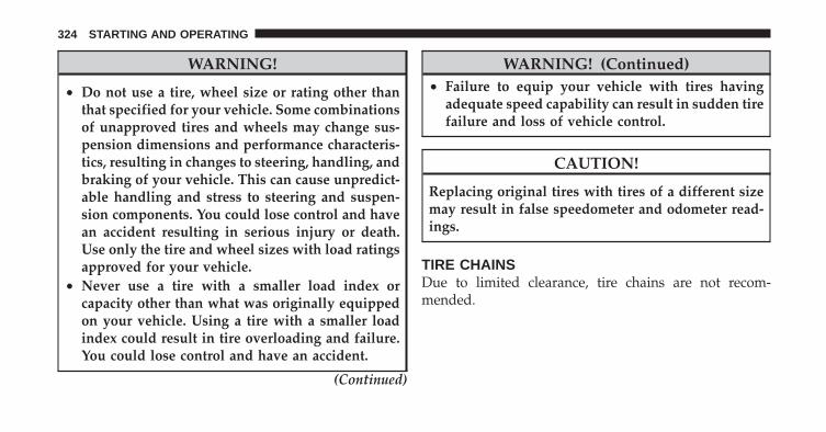
WARNING!
• Do not use a tire, wheel size or rating other thanthat specified for your vehicle. Some combinationsof unapproved tires and wheels may change sus-pension dimensions and performance characteris-tics, resulting in changes to steering, handling, andbraking of your vehicle. This can cause unpredict-able handling and stress to steering and suspen-sion components. You could lose control and havean accident resulting in serious injury or death.Use only the tire and wheel sizes with load ratingsapproved for your vehicle.
• Never use a tire with a smaller load index orcapacity other than what was originally equippedon your vehicle. Using a tire with a smaller loadindex could result in tire overloading and failure.You could lose control and have an accident.
(Continued)
WARNING! (Continued)• Failure to equip your vehicle with tires having
adequate speed capability can result in sudden tirefailure and loss of vehicle control.
CAUTION!
Replacing original tires with tires of a different sizemay result in false speedometer and odometer read-ings.
TIRE CHAINSDue to limited clearance, tire chains are not recom-mended.
324 STARTING AND OPERATING
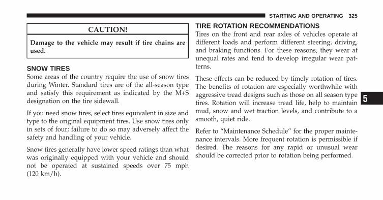
CAUTION!
Damage to the vehicle may result if tire chains areused.
SNOW TIRESSome areas of the country require the use of snow tiresduring Winter. Standard tires are of the all-season typeand satisfy this requirement as indicated by the M+Sdesignation on the tire sidewall.
If you need snow tires, select tires equivalent in size andtype to the original equipment tires. Use snow tires onlyin sets of four; failure to do so may adversely affect thesafety and handling of your vehicle.
Snow tires generally have lower speed ratings than whatwas originally equipped with your vehicle and shouldnot be operated at sustained speeds over 75 mph(120 km/h).
TIRE ROTATION RECOMMENDATIONSTires on the front and rear axles of vehicles operate atdifferent loads and perform different steering, driving,and braking functions. For these reasons, they wear atunequal rates and tend to develop irregular wear pat-terns.
These effects can be reduced by timely rotation of tires.The benefits of rotation are especially worthwhile withaggressive tread designs such as those on all season typetires. Rotation will increase tread life, help to maintainmud, snow and wet traction levels, and contribute to asmooth, quiet ride.
Refer to “Maintenance Schedule” for the proper mainte-nance intervals. More frequent rotation is permissible ifdesired. The reasons for any rapid or unusual wearshould be corrected prior to rotation being performed.
5
STARTING AND OPERATING 325

The suggested rotation method is shown in the followingdiagram.
TIRE PRESSURE MONITORING SYSTEM (TPMS)The Tire Pressure Monitor System (TPMS) will warn thedriver of a low tire pressure based on the vehicle recom-mended cold placard pressure.
The tire pressure will vary with temperature by about1 psi (6.9 kPa) for every 12°F (6.5°C). This means thatwhen the outside temperature decreases, the tire pressurewill decrease. Tire pressure should always be set basedon “cold inflation tire pressure”. This is defined as the tirepressure after the vehicle has not been driven for at leastthree hours, or driven less than 1 mile (1.6 km) after athree hour period. The cold tire inflation pressure mustnot exceed the maximum inflation pressure molded intothe tire sidewall. Refer to “Tires – General Information”in “Starting and Operating” for information on how toproperly inflate the vehicle’s tires. The tire pressure willalso increase as the vehicle is driven - this is normal andthere should be no adjustment for this increased pres-sure.
The TPMS will warn the driver of a low tire pressure ifthe tire pressure falls below the low-pressure warninglimit for any reason, including low temperature effects, ornatural pressure loss through the tire.
Tire Rotation
326 STARTING AND OPERATING
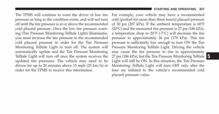
The TPMS will continue to warn the driver of low tirepressure as long as the condition exists, and will not turnoff until the tire pressure is at or above the recommendedcold placard pressure. Once the low tire pressure warn-ing (Tire Pressure Monitoring Telltale Light) illuminates,you must increase the tire pressure to the recommendedcold placard pressure in order for the Tire PressureMonitoring Telltale Light to turn off. The system willautomatically update and the Tire Pressure MonitoringTelltale Light will turn off once the system receives theupdated tire pressures. The vehicle may need to bedriven for up to 20 minutes above 15 mph (25 km/h) inorder for the TPMS to receive this information.
For example, your vehicle may have a recommendedcold (parked for more than three hours) placard pressureof 30 psi (207 kPa). If the ambient temperature is 68°F(20°C) and the measured tire pressure is 27 psi (186 kPa),a temperature drop to 20°F (-7°C) will decrease the tirepressure to approximately 26 psi (179 kPa). This tirepressure is sufficiently low enough to turn ON the TirePressure Monitoring Telltale Light. Driving the vehiclemay cause the tire pressure to rise to approximately27 psi (186 kPa), but the Tire Pressure Monitoring TelltaleLight will still be ON. In this situation, the Tire PressureMonitoring Telltale Light will turn OFF only after thetires are inflated to the vehicle’s recommended coldplacard pressure value.
5
STARTING AND OPERATING 327
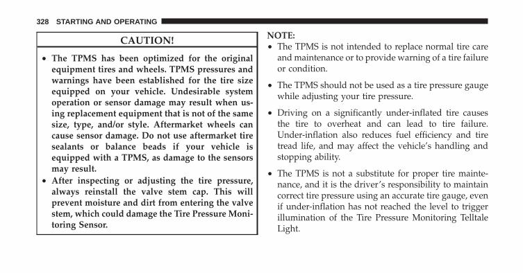
CAUTION!
• The TPMS has been optimized for the originalequipment tires and wheels. TPMS pressures andwarnings have been established for the tire sizeequipped on your vehicle. Undesirable systemoperation or sensor damage may result when us-ing replacement equipment that is not of the samesize, type, and/or style. Aftermarket wheels cancause sensor damage. Do not use aftermarket tiresealants or balance beads if your vehicle isequipped with a TPMS, as damage to the sensorsmay result.
• After inspecting or adjusting the tire pressure,always reinstall the valve stem cap. This willprevent moisture and dirt from entering the valvestem, which could damage the Tire Pressure Moni-toring Sensor.
NOTE:• The TPMS is not intended to replace normal tire care
and maintenance or to provide warning of a tire failureor condition.
• The TPMS should not be used as a tire pressure gaugewhile adjusting your tire pressure.
• Driving on a significantly under-inflated tire causesthe tire to overheat and can lead to tire failure.Under-inflation also reduces fuel efficiency and tiretread life, and may affect the vehicle’s handling andstopping ability.
• The TPMS is not a substitute for proper tire mainte-nance, and it is the driver’s responsibility to maintaincorrect tire pressure using an accurate tire gauge, evenif under-inflation has not reached the level to triggerillumination of the Tire Pressure Monitoring TelltaleLight.
328 STARTING AND OPERATING

• Seasonal temperature changes will affect tire pressure,and the TPMS will monitor the actual tire pressure inthe tire.
Base SystemThis is the TPMS warning indicator located in theinstrument cluster.
The TPMS uses wireless technology with wheel rimmounted electronic sensors to monitor tire pressure lev-els. Sensors, mounted to each wheel as part of the valvestem, transmit tire pressure readings to the ReceiverModule.
NOTE: It is particularly important for you to check thetire pressure in all of the tires on your vehicle regularlyand to maintain the proper pressure.
The TPMS consists of the following components:
• Receiver Module
• Four Tire Pressure Monitoring Sensors
• Tire Pressure Monitoring Telltale Light
Tire Pressure Monitoring Low Pressure WarningsThe Tire Pressure Monitoring Telltale Light will illumi-nate in the instrument cluster, and an audible chime willbe activated when one or more of the four active road tirepressures are low. Should this occur, you should stop assoon as possible, check the inflation pressure of each tireon your vehicle, and inflate each tire to the vehicle’srecommended cold placard pressure value. The systemwill automatically update and the Tire Pressure Monitor-ing Light will extinguish once the updated tire pressureshave been received. The vehicle may need to be drivenfor up to 20 minutes above 15 mph (25 km/h) to receivethis information.
Check TPMS WarningsThe Tire Pressure Monitoring Telltale Light will flash onand off for 75 seconds and remain on solid when a system
5
STARTING AND OPERATING 329
fault is detected. The system fault will also sound achime. If the ignition key is cycled, this sequence willrepeat providing the system fault still exists. The TirePressure Monitoring Telltale Light will turn off when thefault condition no longer exists. A system fault can occurwith any of the following scenarios:
1. Jamming due to electronic devices or driving next tofacilities emitting the same radio frequencies as the TPMsensors.
2. Installing some form of aftermarket window tintingthat affects radio wave signals.
3. Snow or ice around the wheels or wheel housings.
4. Using tire chains on the vehicle.
5. Using wheels/tires not equipped with TPM sensors.
NOTE: Your vehicle is equipped with a compact sparewheel and tire assembly.
1. The compact spare tire does not have a tire pressuremonitoring sensor. Therefore, the TPMS will not monitorthe tire pressure in the compact spare tire.
2. If you install the compact spare tire in place of a roadtire that has a pressure below the low-pressure warninglimit, upon the next ignition key cycle, a chime willsound and the Tire Pressure Monitoring Telltale Lightwill still turn ON due to the low tire.
3. However, after driving the vehicle for up to 20 min-utes above 15 mph (25 km/h), the Tire Pressure Moni-toring Telltale Light will flash on and off for 75 secondsand then remain on solid.
4. For each subsequent ignition key cycle, a chime willsound and the Tire Pressure Monitoring Telltale Lightwill flash on and off for 75 seconds and then remain onsolid.
330 STARTING AND OPERATING

5. Once you repair or replace the original road tire andreinstall it on the vehicle in place of the compact sparetire, the TPMS will update automatically and the TirePressure Monitoring Telltale Light will turn OFF, as longas no tire pressure is below the low-pressure warninglimit in any of the four active road tires. The vehicle mayneed to be driven for up to 20 minutes above 15 mph(25 km/h) in order for the TPMS to receive thisinformation.
Premium System – If EquippedThe TPMS uses wireless technology with wheel rimmounted electronic sensors to monitor tire pressure lev-els. Sensors, mounted to each wheel as part of the valvestem, transmit tire pressure readings to the receivermodule.
NOTE: It is particularly important for you to check thetire pressure in all of your tires regularly and to maintainthe proper pressure.
The TPMS consists of the following components:
• Receiver Module
• Four Tire Pressure Monitoring Sensors
• Three Trigger Modules (mounted in three of the fourwheel wells)
• Various Tire Pressure Monitoring System Messages,which display in the Electronic Vehicle InformationCenter (EVIC)
• Yellow Tire Pressure Monitoring Telltale Light
Tire Pressure Monitoring Low Pressure WarningsThe Tire Pressure Monitoring Telltale Light will illumi-nate in the instrument cluster and an audible chime willbe activated when one or more of the four active road tirepressures are low. The audible chime will sound once
5
STARTING AND OPERATING 331

every ignition cycle for each condition that it detects. Inaddition, the EVIC will display a graphic of the pressurevalue(s) with the low tire(s) flashing.
Should a low tire condition occur on any of the fouractive road tire(s), you should stop as soon as possibleand inflate all tires that are flashing on the graphic
display to the vehicle’s recommended cold placard pres-sure value. The system will automatically update, thegraphic display of the pressure value(s) will stop flash-ing, and the Tire Pressure Monitoring Light will extin-guish once the updated tire pressure(s) have been re-ceived. The vehicle may need to be driven for up to20 minutes above 15 mph (25 km/h) to receive thisinformation.
Check TPMS MessageThe Tire Pressure Monitoring Telltale Light will flash onand off for 75 seconds, and remain on solid when asystem fault is detected. The system fault will also sounda chime. The EVIC will display a “CHECK TPM SYS-TEM” message for three seconds. This text message isthen followed by a graphic display, with “- -“ in place ofthe pressure value(s) indicating which Tire PressureMonitoring Sensor(s) is not being received.
Low Tire Pressure Display
332 STARTING AND OPERATING

If the ignition key is cycled, this sequence will repeat,providing the system fault still exists. If the system faultno longer exists, the Tire Pressure Monitoring TelltaleLight will no longer flash, the �CHECK TPM SYSTEM�text message will not be present, and a pressure value
will be displayed instead of dashes. A system fault canoccur with any of the following scenarios:
1. Jamming due to electronic devices or driving next tofacilities emitting the same radio frequencies as the TPMsensors.
2. Installing some form of aftermarket window tintingthat affects radio wave signals.
3. Snow or ice around the wheels or wheel housings.
4. Using tire chains on the vehicle.
5. Using wheels/tires not equipped with TPM sensors.
NOTE: Your vehicle is equipped with a compact sparewheel and tire assembly.
1. The compact spare tire does not have a tire pressuremonitoring sensor. Therefore, the TPMS will not monitorthe tire pressure in the compact spare tire.
Check TPM System Display
5
STARTING AND OPERATING 333

2. If you install the compact spare tire in place of a roadtire that has a pressure below the low-pressure warninglimit, upon the next ignition key cycle, a chime willsound and the Tire Pressure Monitoring Telltale Lightwill still turn ON due to the low tire.
3. However, after driving the vehicle for up to 20 min-utes above 15 mph (25 km/h), the Tire Pressure Moni-toring Telltale Light will flash on and off for 75 secondsand then remain on solid. In addition, the EVIC willdisplay a “CHECK TPM SYSTEM” message for threeseconds and then display dashes (- -) in place of thepressure values.
4. For each subsequent ignition key cycle, a chime willsound and the Tire Pressure Monitoring Telltale Lightwill flash on and off for 75 seconds and then remain onsolid, and the EVIC will display a “CHECK TPM SYS-TEM” message for three seconds and then display dashes(- -) in place of the pressure values.
5. Once you repair or replace the original road tire andreinstall it on the vehicle in place of the compact sparetire, the TPMS will update automatically and the TirePressure Monitoring Telltale Light will turn OFF, as longas no tire pressure is below the low-pressure warninglimit in any of the four active road tires. The vehicle mayneed to be driven for up to 20 minutes above 15 mph(25 km/h) in order for the TPMS to receive thisinformation.
General InformationThis device complies with Part 15 of the FCC rules andRSS 210 of Industry Canada. Operation is subject to thefollowing conditions:
• This device may not cause harmful interference.
• This device must accept any interference received,including interference that may cause undesiredoperation.
334 STARTING AND OPERATING

The tire pressure sensors are covered under one of thefollowing licenses:
United States . . . . . . . . . . . . . . . . . . . . . KR5S120123Canada . . . . . . . . . . . . . . . . . . . . . . . . 2671-S120123
FUEL REQUIREMENTSYour vehicle is designed to meet all emis-sion regulations and provide excellent fueleconomy when using high-quality regularunleaded gasoline with an octane rating of87. The use of premium gasoline is notrecommended, as it will not provide any
benefit over regular gasoline in these engines.
Light spark knock at low engine speeds is not harmful toyour engine. However, continued heavy spark knock athigh speeds can cause damage and immediate service isrequired.
Poor quality gasoline can cause problems such as hardstarting, stalling and hesitations. If you experience thesesymptoms, try another brand of gasoline (with the ap-propriate octane rating for your engine) before consider-ing service for the vehicle.
Reformulated GasolineMany areas of the country require the use of cleanerburning gasoline referred to as “Reformulated Gasoline.”Reformulated gasoline contains oxygenates and are spe-cifically blended to reduce vehicle emissions and im-prove air quality.
The manufacturer supports the use of reformulated gaso-line. Properly blended reformulated gasoline will pro-vide excellent performance and durability of engine andfuel system components.
5
STARTING AND OPERATING 335

Gasoline/Oxygenate BlendsSome fuel suppliers blend unleaded gasoline with oxy-genates such as 10% ethanol, MTBE, and ETBE. Oxygen-ates are required in some areas of the country during thewinter months to reduce carbon monoxide emissions.Fuels blended with these oxygenates may be used inyour vehicle.
CAUTION!
DO NOT use gasoline containing Methanol or E85Ethanol. Use of these blends may result in startingand driveability problems and may damage criticalfuel system components.
Problems that result from using methanol/gasolineblends are not the responsibility of the manufacturer.While MTBE is an oxygenate made from Methanol, itdoes not have the negative effects of Methanol.
E85 Usage In Non-Flex Fuel VehiclesNon-FFV vehicles are compatible with gasoline contain-ing 10% ethanol (E10). Gasoline with higher ethanolcontent may void the vehicle’s warranty.
If a Non-FFV vehicle is inadvertently fueled with E85fuel, the engine will have some or all of these symptoms:
• operate in a lean mode
• OBD II “Malfunction Indicator Light” on
• poor engine performance
• poor cold start and cold driveability
• increased risk for fuel system component corrosion
To fix a Non-FFV vehicle inadvertently fueled once withE85 perform the following:
• drain the fuel tank (see your authorized dealer)
• change the engine oil and oil filter
336 STARTING AND OPERATING

• disconnect and reconnect the battery to reset theengine controller memory
More extensive repairs will be required for prolongedexposure to E85 fuel.
MMT In GasolineMMT is a manganese containing metallic additive that isblended into some gasoline to increase the octane num-ber. Gasoline blended with MMT offers no performanceadvantage beyond gasoline of the same octane numberwithout MMT. Gasoline blended with MMT have beenshown to reduce spark plug life and reduce emissionsystem performance in some vehicles. The manufacturerrecommends using gasoline without MMT. Since theMMT content of gasoline may not be indicated on thepump, you should ask your gasoline retailer whether ornot their gasoline contains MMT.
It is even more important to look for gasoline withoutMMT in Canada, because MMT can be used at levelshigher than those allowed in the United States.
MMT is prohibited in Federal and California reformu-lated gasoline.
Materials Added To FuelAll gasoline sold in the United States is required tocontain effective detergent additives. Use of additionaldetergents or other additives is not needed under normalconditions and would result in additional cost. Thereforeyou should not have to add anything to the fuel.
5
STARTING AND OPERATING 337
Fuel System Cautions
CAUTION!
Follow these guidelines to maintain your vehicle’sperformance:• The use of leaded gas is prohibited by Federal law.
Using leaded gasoline can impair engine perfor-mance and damage the emission control system.
• An out-of-tune engine, or certain fuel or ignitionmalfunctions, can cause the catalytic converter tooverheat. If you notice a pungent burning odor orsome light smoke, your engine may be out of tuneor malfunctioning and may require immediateservice. Contact your authorized dealer for serviceassistance.
(Continued)
CAUTION! (Continued)• The use of fuel additives, which are now being
sold as octane enhancers, is not recommended.Most of these products contain high concentra-tions of Methanol. Fuel system damage or vehicleperformance problems resulting from the use ofsuch fuels or additives is not the responsibility ofthe manufacturer.
NOTE: Intentional tampering with emissions controlsystems can result in civil penalties being assessedagainst you.
338 STARTING AND OPERATING
Carbon Monoxide Warnings
WARNING!
Carbon monoxide (CO) in exhaust gases is deadly.Follow the precautions below to prevent carbonmonoxide poisoning:• Do not inhale exhaust gases. They contain carbon
monoxide, a colorless and odorless gas which cankill. Never run the engine in a closed area, such asa garage, and never sit in a parked vehicle with theengine running for an extended period of time. Ifthe vehicle is stopped in an open area with theengine running for more than a short period,adjust the ventilation system to force fresh, out-side air into the vehicle.
(Continued)
WARNING! (Continued)• Guard against carbon monoxide with proper
maintenance. Have the exhaust system inspectedevery time the vehicle is raised. Have any abnor-mal conditions repaired promptly. Until repaired,drive with all side windows fully open.
• Keep the liftgate closed when driving your vehicleto prevent carbon monoxide and other poisonousexhaust gases from entering the vehicle.
ADDING FUEL
Fuel Filler Cap (Gas Cap)
The gas cap is behind the fuel filler door, on the left sideof the vehicle. If the gas cap is lost or damaged, be surethe replacement cap is for use with this vehicle.
5
STARTING AND OPERATING 339
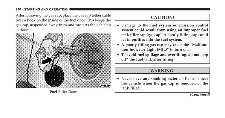
After removing the gas cap, place the gas cap tether cableover a hook on the inside of the fuel door. This keeps thegas cap suspended away from and protects the vehicle’ssurface.
CAUTION!
• Damage to the fuel system or emission controlsystem could result from using an improper fueltank filler cap (gas cap). A poorly fitting cap couldlet impurities into the fuel system.
• A poorly fitting gas cap may cause the “Malfunc-tion Indicator Light (MIL)” to turn on.
• To avoid fuel spillage and overfilling, do not “topoff” the fuel tank after filling.
WARNING!
• Never have any smoking materials lit in or nearthe vehicle when the gas cap is removed or thetank filled.
(Continued)Fuel Filler Door
340 STARTING AND OPERATING

WARNING! (Continued)• Never add fuel when the engine is running. This is
in violation of most state and Federal fire regula-tions and may cause the MIL to turn on.
• A fire may result if gasoline is pumped into aportable container that is inside of a vehicle. Youcould be burned. Always place gas containers onthe ground while filling.
NOTE:• When the fuel nozzle “clicks” or shuts off, the fuel
tank is full.
• Tighten the gas cap about 1/4 turn until you hear oneclick. This is an indication that cap is properly tight-ened.
• If the gas cap is not tighten properly, the MIL willcome on. Be sure the gas cap is tightened every timethe vehicle is refueled.
Loose Fuel Filler Cap MessageIf the vehicle diagnostic system determines that the fuelfiller cap is loose or improperly installed, a “gASCAP”message will be displayed in the Odometer/Trip Odom-eter in the instrument cluster. Refer to “InstrumentCluster Description” in “Understanding Your InstrumentPanel” for further information. Tighten the fuel filler capproperly and press the odometer/trip odometer RESETbutton to turn the message off. If the problem continues,the message will appear the next time the vehicle isstarted. Refer to “Onboard Diagnostic System” in “Main-taining Your Vehicle” for further information.
VEHICLE LOADINGAs required by National Highway Traffic Safety Admin-istration regulations, your vehicle has a certification labelaffixed to the driver’s side door or B-Pillar.
5
STARTING AND OPERATING 341

Vehicle Certification LabelYour vehicle has a Vehicle Certification Label attached tothe driver’s door B-Pillar.
The label contains the following information:
• Name of manufacturer
• Month and year of manufacture
• Gross Vehicle Weight Rating (GVWR)
• Vehicle Identification Number (VIN)
• Type of Vehicle
• Month, Day and Hour of Manufacture (MDH)
The bar code allows a computer scanner to read theVehicle Identification Number (VIN).
Gross Vehicle Weight Rating (GVWR)The GVWR is the total allowable weight of your vehicle.This includes driver, passengers, and cargo. The totalload must be limited so that you do not exceed theGVWR.
Tire SizeThe tire size on the Vehicle Certification Label representsthe actual tire size on your vehicle. Replacement tiresmust be equal to the load capacity of this tire size.
Rim SizeThis is the rim size that is appropriate for the tire sizelisted.
Inflation PressureThis is the cold tire inflation pressure for your vehicle, forall loading conditions.
342 STARTING AND OPERATING

Curb WeightThe curb weight of a vehicle is defined as the total weightof the vehicle with all fluids, including vehicle fuel, at fullcapacity conditions, and with no occupants or cargoloaded into the vehicle. The front and rear curb weightvalues are determined by weighing your vehicle on acommercial scale before any occupants or cargo areadded.
OverloadingThe load carrying components (springs, tires, wheels,etc.) of your vehicle will provide satisfactory service aslong as you do not exceed the GVWR.
The best way to figure out the total weight of yourvehicle is to weigh it when it is fully loaded and ready foroperation. Weigh it on a commercial scale to ensure thatit is not over the GVWR.
Overloading can cause potential safety hazards andshorten useful service life. Heavier suspension compo-nents do not necessarily increase the vehicle’s GVWR.
LoadingTo load your vehicle properly, first figure out its emptyweight. Store heavier items down low and be sure youdistribute their weight as evenly as possible. Stow allloose items securely before driving. Improper weightdistribution can have an adverse effect on the way yourvehicle steers and handles, and the way the brakesoperate.
CAUTION!
Do not load your vehicle any heavier than theGVWR. If you do, parts on your vehicle can break, orit can change the way your vehicle handles. Thiscould cause you to lose control. Also, overloading canshorten the life of your vehicle.
5
STARTING AND OPERATING 343

TRAILER TOWINGIn this section you will find safety tips and informationon limits to the type of towing you can reasonably dowith your vehicle. Before towing a trailer, carefullyreview this information to tow your load as efficientlyand safely as possible.
To maintain warranty coverage, follow the requirementsand recommendations in this manual concerning ve-hicles used for trailer towing.
Common Towing DefinitionsThe following trailer towing related definitions will assistyou in understanding the information:
Gross Vehicle Weight Rating (GVWR)The GVWR is the total allowable weight of your vehicle.This includes driver, passengers, cargo and tongueweight. The total load must be limited so that you do notexceed the GVWR.
Gross Trailer Weight (GTW)The GTW is the weight of the trailer plus the weight of allcargo, consumables and equipment (permanent or tem-porary) loaded in or on the trailer in its �loaded andready for operation� condition. The recommended way tomeasure GTW is to put your fully loaded trailer on avehicle scale. The entire weight of the trailer must besupported by the scale.
Gross Combination Weight Rating (GCWR)The GCWR is the total permissible weight of your vehicleand trailer when weighed in combination.
NOTE: The GCWR rating includes a 150 lbs (68 kg)allowance for the presence of a driver.
Gross Axle Weight Rating (GAWR)The GAWR is the maximum capacity of the front and rearaxles. Distribute the load over the front and rear axlesevenly. Make sure that you do not exceed either front orrear GAWR.
344 STARTING AND OPERATING
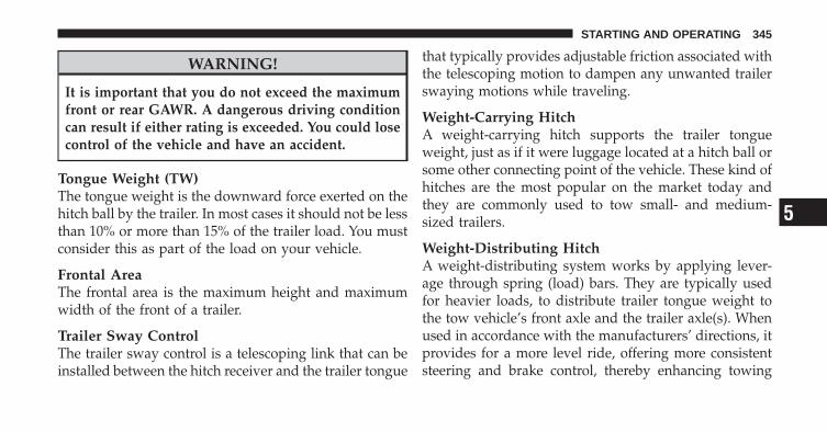
WARNING!
It is important that you do not exceed the maximumfront or rear GAWR. A dangerous driving conditioncan result if either rating is exceeded. You could losecontrol of the vehicle and have an accident.
Tongue Weight (TW)The tongue weight is the downward force exerted on thehitch ball by the trailer. In most cases it should not be lessthan 10% or more than 15% of the trailer load. You mustconsider this as part of the load on your vehicle.
Frontal AreaThe frontal area is the maximum height and maximumwidth of the front of a trailer.
Trailer Sway ControlThe trailer sway control is a telescoping link that can beinstalled between the hitch receiver and the trailer tongue
that typically provides adjustable friction associated withthe telescoping motion to dampen any unwanted trailerswaying motions while traveling.
Weight-Carrying HitchA weight-carrying hitch supports the trailer tongueweight, just as if it were luggage located at a hitch ball orsome other connecting point of the vehicle. These kind ofhitches are the most popular on the market today andthey are commonly used to tow small- and medium-sized trailers.
Weight-Distributing HitchA weight-distributing system works by applying lever-age through spring (load) bars. They are typically usedfor heavier loads, to distribute trailer tongue weight tothe tow vehicle’s front axle and the trailer axle(s). Whenused in accordance with the manufacturers’ directions, itprovides for a more level ride, offering more consistentsteering and brake control, thereby enhancing towing
5
STARTING AND OPERATING 345

safety. The addition of a friction/hydraulic sway controlalso dampens sway caused by traffic and crosswinds andcontributes positively to tow vehicle and trailer stability.Trailer sway control and a weight distributing (loadequalizing) hitch are recommended for heavier TongueWeights (TW) and may be required depending on Vehicleand Trailer configuration/loading to comply with GrossAxle Weight Rating (GAWR) requirements.
Trailer Hitch ClassificationYour vehicle may be factory equipped for safe towing oftrailers weighing over 2,000 lbs (907 kg) with the optionalTrailer Tow Prep Package. See your authorized dealer forpackage content.
The following chart provides the industry standard forthe maximum trailer weight a given trailer hitch class cantow and should be used to assist you in selecting thecorrect trailer hitch for your intended towing condition.
Refer to the Trailer Towing Weights (Maximum TrailerWeight Ratings) chart for the maximum GTW towable foryour given drivetrain.
Trailer Hitch Classification DefinitionsClass Max. Trailer Hitch Industry
StandardsClass I - Light Duty 2,000 lbs (907 kg)Class II - MediumDuty
3,500 lbs (1 587 kg)
Class III - Heavy Duty 5,000 lbs (2 268 kg)Class IV - ExtraHeavy Duty
10,000 lbs (4 540 kg)
Refer to the “Trailer Towing Weights (MaximumTrailer Weight Ratings)” chart for the MaximumGross Trailer Weight (GTW) towable for your givendrivetrain.
All trailer hitches should be professionally installed onyour vehicle.
346 STARTING AND OPERATING

Trailer Towing Weights (Maximum Trailer Weight Ratings)The following chart provides the maximum trailer weight ratings towable for your given drivetrain.
Engine/Transaxle Frontal Area Max. GTW (Gross Trailer Wt.) Max. Tongue Wt. (See Note 1)2.0L Auto/Man 22 sq ft (2.04 sq m) 1,000 lbs (450 kg) 150 lbs (50 kg)2.4L Auto/Man 22 sq ft (2.04 sq m) 1,000 lbs (450 kg) 150 lbs (50 kg)2.4L Auto/Man withTrailer Tow PrepPackage (AHC)
32 sq ft (3.0 sq m) 2,000 lbs (907 kg) 300 lbs (136 kg)
Refer to local laws for maximum trailer towing speeds.
Note 1 – The trailer tongue weight must be considered aspart of the combined weight of occupants and cargo, andshould never exceed the weight referenced on the Tireand Loading Information placard. Refer to “Tire SafetyInformation” in “Starting and Operating” for furtherinformation.
Trailer and Tongue WeightAlways load a trailer with 60% to 65% of the weight inthe front of the trailer. This places 10% to 15% of theGross Trailer Weight (GTW) on the tow hitch of yourvehicle. Loads balanced over the wheels or heavier in therear can cause the trailer to sway severely from side-to-side which will cause loss of control of the vehicle andtrailer. Failure to load trailers heavier in front is the causeof many trailer accidents.
5
STARTING AND OPERATING 347

Never exceed the maximum trailer tongue weightstamped on your bumper or trailer hitch.
Consider the following items when computing theweight on the rear axle of the vehicle:
• The trailer tongue weight of the trailer.
• The weight of any other type of cargo or equipmentput in or on your vehicle.
• The weight of the driver and all passengers.
NOTE: Remember that everything put into or on thetrailer adds to the load on your vehicle. Also, additionalfactory-installed options, or authorized dealer-installedoptions, must be considered as part of the total load onyour vehicle. Refer to the Tire and Loading Informationplacard in “Tire Safety Information” for the maximumcombined weight of occupants and cargo for yourvehicle.
Towing RequirementsTo promote proper break-in of your vehicle drivetraincomponents, the following guidelines are recommended:
CAUTION!
• Do not tow a trailer at all during the first 500 miles(805 km) the new vehicle is driven. The engine,axle or other parts could be damaged.
(Continued)
348 STARTING AND OPERATING

CAUTION! (Continued)• Then, during the first 500 miles (805 km) that a
trailer is towed, do not drive over 50 mph(80 km/h) and do not make starts at full throttle.This helps the engine and other parts of thevehicle wear in at the heavier loads.
Perform the maintenance listed in the “MaintenanceSchedule.” Refer to “Maintenance Schedule” for furtherinformation. When towing a trailer, never exceed theGAWR, or GCWR, ratings.
WARNING!
Improper towing can lead to an injury accident.Follow these guidelines to make your trailer towingas safe as possible:
(Continued)
WARNING! (Continued)• Make certain that the load is secured in the trailer
and will not shift during travel. When traileringcargo that is not fully secured, dynamic load shiftscan occur that may be difficult for the driver tocontrol. You could lose control of your vehicle andhave an accident.
• When hauling cargo or towing a trailer, do notoverload your vehicle or trailer. Overloading cancause a loss of control, poor performance or dam-age to brakes, axle, engine, transaxle, steering,suspension, chassis structure or tires.
• Safety chains must always be used between yourvehicle and trailer. Always connect the chains tothe frame or hook retainers of the vehicle hitch.Cross the chains under the trailer tongue andallow enough slack for turning corners.
(Continued)
5
STARTING AND OPERATING 349

WARNING! (Continued)• Vehicles with trailers should not be parked on a
grade. When parking, apply the parking brake onthe tow vehicle. Put the tow vehicle automatictransmission in PARK. Always block or �chock�the trailer wheels.
• GCWR must not be exceeded.• Total weight must be distributed between the tow
vehicle and the trailer such that the following fourratings are not exceeded:1. GVWR2. GTW3. GAWR4. Tongue weight rating for the trailer hitch uti-lized (This requirement may limit the ability toalways achieve the 10% to 15% range of tongueweight as a percentage of total trailer weight).
Towing Requirements – Tires
− Do not attempt to tow a trailer while using a compactspare tire.
− Proper tire inflation pressures are essential to the safeand satisfactory operation of your vehicle. Refer to“Tires – General Information” in “Starting and Oper-ating” for proper tire inflation procedures.
− Check the trailer tires for proper tire inflation pres-sures before trailer usage.
− Check for signs of tire wear or visible tire damagebefore towing a trailer. Refer to “Tires – GeneralInformation” in “Starting and Operating” for theproper inspection procedure.
− When replacing tires, refer to “Tires – General Infor-mation” in “Starting and Operating” for proper tire
350 STARTING AND OPERATING
replacement procedures. Replacing tires with a higherload carrying capacity will not increase the vehicle’sGVWR and GAWR limits.
Towing Requirements – Trailer Brakes
− Do not interconnect the hydraulic brake system orvacuum system of your vehicle with that of the trailer.This could cause inadequate braking and possiblepersonal injury.
− An electronically actuated trailer brake controller isrequired when towing a trailer with electronicallyactuated brakes. When towing a trailer equipped witha hydraulic surge actuated brake system, an electronicbrake controller is not required.
− Trailer brakes are recommended for trailers over1,000 lbs (454 kg) and required for trailers in excess of2,000 lbs (907 kg).
CAUTION!
If the trailer weighs more than 1,000 lbs (454 kg)loaded, it should have its own brakes and theyshould be of adequate capacity. Failure to do thiscould lead to accelerated brake lining wear, higherbrake pedal effort, and longer stopping distances.
WARNING!
• Do not connect trailer brakes to your vehicle’shydraulic brake lines. It can overload your brakesystem and cause it to fail. You might not havebrakes when you need them and could have anaccident.
• Towing any trailer will increase your stopping dis-tance. When towing you should allow for additionalspace between your vehicle and the vehicle in frontof you. Failure to do so could result in an accident.
(Continued)
5
STARTING AND OPERATING 351

Towing Requirements – Trailer Lights and WiringYour authorized dealer offers a trailer wiring harnessdesigned specifically for your vehicle.
Whenever you pull a trailer, regardless of the trailer size,stop lights and turn signals on the trailer are required formotoring safety.
The Trailer Tow Package may include a four- and seven-pin wiring harness. Use a factory approved trailer har-ness and connector.
NOTE: Do not cut or splice wiring into the vehicleswiring harness.
The electrical connections are all complete to the vehiclebut you must mate the harness to a trailer connector.Refer to the following illustrations.
Four-Pin Connector
1 — Female Pins 4 — Park2 — Male Pin 5 — Left Stop/Turn3 — Ground 6 — Right Stop/Turn
352 STARTING AND OPERATING
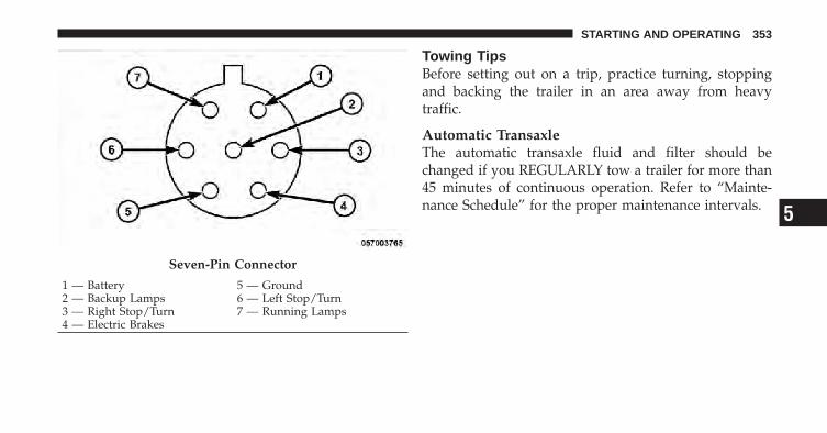
Towing TipsBefore setting out on a trip, practice turning, stoppingand backing the trailer in an area away from heavytraffic.
Automatic TransaxleThe automatic transaxle fluid and filter should bechanged if you REGULARLY tow a trailer for more than45 minutes of continuous operation. Refer to “Mainte-nance Schedule” for the proper maintenance intervals.
Seven-Pin Connector
1 — Battery 5 — Ground2 — Backup Lamps 6 — Left Stop/Turn3 — Right Stop/Turn 7 — Running Lamps4 — Electric Brakes
5
STARTING AND OPERATING 353
Electronic Speed Control – If Equipped
− Do not use in hilly terrain or with heavy loads.
− When using the speed control, if you experience speeddrops greater than 10 mph (16 km/h), disengage untilyou can get back to cruising speed.
− Use speed control in flat terrain and with light loads tomaximize fuel efficiency.
Cooling SystemTo reduce the potential for engine and transaxle over-heating, take the following actions:
− City DrivingWhen stopped for short periods of time, shift the trans-axle into NEUTRAL but do not increase engine idlespeed.
− Highway DrivingReduce speed.
− Air ConditioningTurn off temporarily.
354 STARTING AND OPERATING
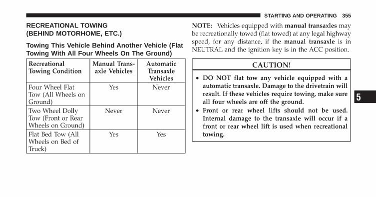
RECREATIONAL TOWING(BEHIND MOTORHOME, ETC.)
Towing This Vehicle Behind Another Vehicle (FlatTowing With All Four Wheels On The Ground)
RecreationalTowing Condition
Manual Trans-axle Vehicles
AutomaticTransaxleVehicles
Four Wheel FlatTow (All Wheels onGround)
Yes Never
Two Wheel DollyTow (Front or RearWheels on Ground)
Never Never
Flat Bed Tow (AllWheels on Bed ofTruck)
Yes Yes
NOTE: Vehicles equipped with manual transaxles maybe recreationally towed (flat towed) at any legal highwayspeed, for any distance, if the manual transaxle is inNEUTRAL and the ignition key is in the ACC position.
CAUTION!
• DO NOT flat tow any vehicle equipped with aautomatic transaxle. Damage to the drivetrain willresult. If these vehicles require towing, make sureall four wheels are off the ground.
• Front or rear wheel lifts should not be used.Internal damage to the transaxle will occur if afront or rear wheel lift is used when recreationaltowing.
5
STARTING AND OPERATING 355

WHAT TO DO IN EMERGENCIES
CONTENTS
� Hazard Warning Flasher . . . . . . . . . . . . . . . . 358
� If Your Engine Overheats . . . . . . . . . . . . . . . . 358
� Automatic Transaxle Overheating . . . . . . . . . . 360
� Jacking And Tire Changing . . . . . . . . . . . . . . . 360
▫ Jack Location . . . . . . . . . . . . . . . . . . . . . . . 361
▫ Spare Tire Stowage . . . . . . . . . . . . . . . . . . . 361
▫ Preparations For Jacking . . . . . . . . . . . . . . . 361
▫ Jacking Instructions . . . . . . . . . . . . . . . . . . . 362
� Jump-Starting Procedures . . . . . . . . . . . . . . . . 366
▫ Preparations For Jump-Start . . . . . . . . . . . . . 367
▫ Jump-Starting Procedure . . . . . . . . . . . . . . . 368
� Freeing A Stuck Vehicle . . . . . . . . . . . . . . . . . 370
� Towing A Disabled Vehicle . . . . . . . . . . . . . . . 371
▫ With Ignition Key . . . . . . . . . . . . . . . . . . . . 371
▫ Without The Ignition Key . . . . . . . . . . . . . . 373
6
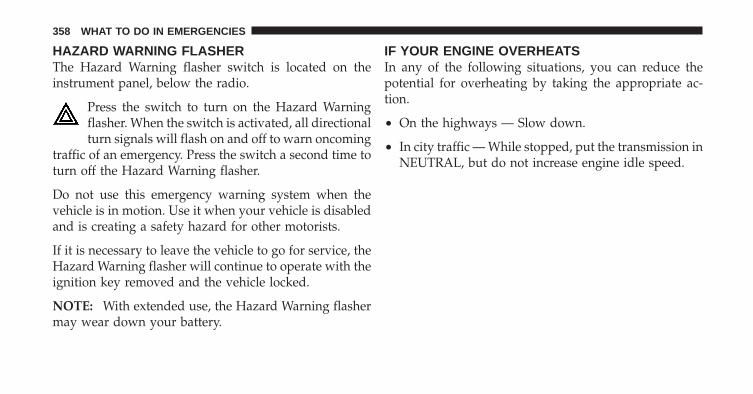
HAZARD WARNING FLASHERThe Hazard Warning flasher switch is located on theinstrument panel, below the radio.
Press the switch to turn on the Hazard Warningflasher. When the switch is activated, all directionalturn signals will flash on and off to warn oncoming
traffic of an emergency. Press the switch a second time toturn off the Hazard Warning flasher.
Do not use this emergency warning system when thevehicle is in motion. Use it when your vehicle is disabledand is creating a safety hazard for other motorists.
If it is necessary to leave the vehicle to go for service, theHazard Warning flasher will continue to operate with theignition key removed and the vehicle locked.
NOTE: With extended use, the Hazard Warning flashermay wear down your battery.
IF YOUR ENGINE OVERHEATSIn any of the following situations, you can reduce thepotential for overheating by taking the appropriate ac-tion.
• On the highways — Slow down.
• In city traffic — While stopped, put the transmission inNEUTRAL, but do not increase engine idle speed.
358 WHAT TO DO IN EMERGENCIES
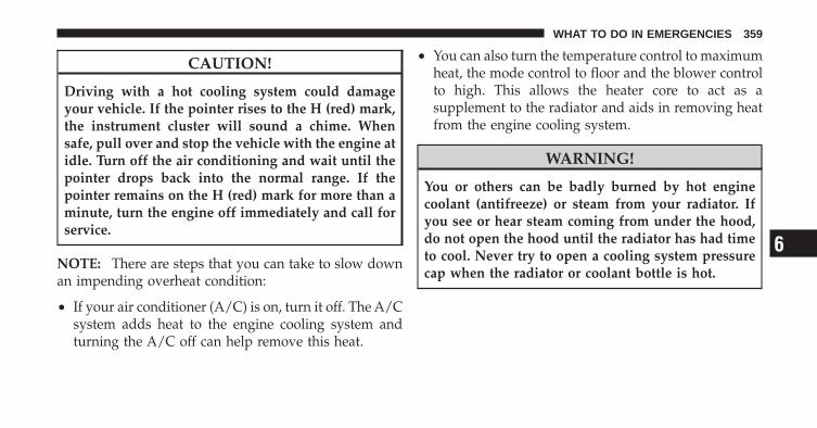
CAUTION!
Driving with a hot cooling system could damageyour vehicle. If the pointer rises to the H (red) mark,the instrument cluster will sound a chime. Whensafe, pull over and stop the vehicle with the engine atidle. Turn off the air conditioning and wait until thepointer drops back into the normal range. If thepointer remains on the H (red) mark for more than aminute, turn the engine off immediately and call forservice.
NOTE: There are steps that you can take to slow downan impending overheat condition:
• If your air conditioner (A/C) is on, turn it off. The A/Csystem adds heat to the engine cooling system andturning the A/C off can help remove this heat.
• You can also turn the temperature control to maximumheat, the mode control to floor and the blower controlto high. This allows the heater core to act as asupplement to the radiator and aids in removing heatfrom the engine cooling system.
WARNING!
You or others can be badly burned by hot enginecoolant (antifreeze) or steam from your radiator. Ifyou see or hear steam coming from under the hood,do not open the hood until the radiator has had timeto cool. Never try to open a cooling system pressurecap when the radiator or coolant bottle is hot.
6
WHAT TO DO IN EMERGENCIES 359
AUTOMATIC TRANSAXLE OVERHEATINGDuring sustained high speed driving or trailer towing uplong grades on hot days, the automatic transaxle oil maybecome too hot.
If this happens, the transmission overheat in-dicator light will come on, and the vehicle willslow slightly until the automatic transaxlecools down enough to allow a return to the
requested speed. If the high speed is maintained, theoverheating will reoccur, as before, in a cyclic fashion.
JACKING AND TIRE CHANGING
WARNING!
• Being under a jacked-up vehicle is dangerous. Thevehicle could slip off the jack and fall on you. Youcould be crushed. Never put any part of your bodyunder a vehicle that is on a jack. Never start or runthe engine while the vehicle is on a jack. If youneed to get under a raised vehicle, take it to aservice center where it can be raised on a lift.
• The jack is designed to use as a tool for changingtires only. The jack should not be used to lift thevehicle for service purposes. The vehicle shouldbe jacked on a firm level surface only. Avoid ice orslippery areas.
360 WHAT TO DO IN EMERGENCIES

Jack LocationThe jack and jack-handle are stowed under the load floorin the cargo area.
Spare Tire StowageThe compact spare tire is stowed under the rear load floorin the cargo area.
Spare Tire RemovalLift up the load floor cover and remove the hold down.
Preparations For Jacking
1. Park the vehicle on a firm level surface, avoiding ice orslippery areas.
WARNING!
Do not attempt to change a tire on the side of thevehicle close to moving traffic. Pull far enough offthe road to avoid the danger of being hit whenoperating the jack or changing the wheel.
2. Set the parking brake.
3. Place the shift lever in PARK (automatic transaxle) orREVERSE (manual transaxle).
4. Turn OFF the ignition.
Spare Tire and Jack Stowage
6
WHAT TO DO IN EMERGENCIES 361
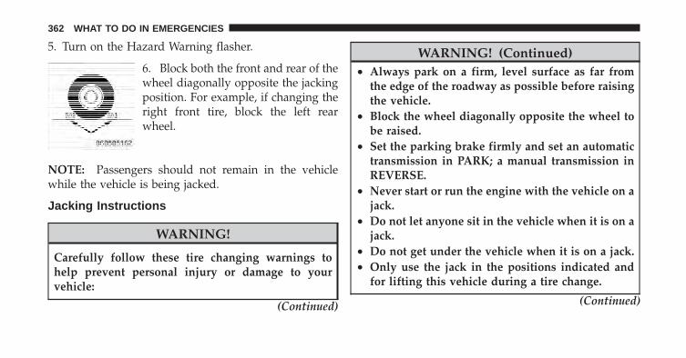
5. Turn on the Hazard Warning flasher.
6. Block both the front and rear of thewheel diagonally opposite the jackingposition. For example, if changing theright front tire, block the left rearwheel.
NOTE: Passengers should not remain in the vehiclewhile the vehicle is being jacked.
Jacking Instructions
WARNING!
Carefully follow these tire changing warnings tohelp prevent personal injury or damage to yourvehicle:
(Continued)
WARNING! (Continued)• Always park on a firm, level surface as far from
the edge of the roadway as possible before raisingthe vehicle.
• Block the wheel diagonally opposite the wheel tobe raised.
• Set the parking brake firmly and set an automatictransmission in PARK; a manual transmission inREVERSE.
• Never start or run the engine with the vehicle on ajack.
• Do not let anyone sit in the vehicle when it is on ajack.
• Do not get under the vehicle when it is on a jack.• Only use the jack in the positions indicated and
for lifting this vehicle during a tire change.
(Continued)
362 WHAT TO DO IN EMERGENCIES

WARNING! (Continued)• If working on or near a roadway, be extremely
careful of motor traffic.• To assure that spare tires, flat or inflated, are
securely stowed, spares must be stowed with thevalve stem facing the ground.
• Turn on the Hazard Warning flasher.
1. Remove the scissors jack and lug wrench from thespare wheel as an assembly. Turn the jack screw to the leftto loosen the lug wrench and remove the wrench fromthe jack assembly.
2. Loosen, but do not remove, the wheel nuts by turningthem to the left one turn while the wheel is still on theground.
Jack Warning LabelJacking Locations
6
WHAT TO DO IN EMERGENCIES 363

CAUTION!
Do not attempt to raise the vehicle by jacking onlocations other than those indicated in Step 3.
3. There are two front jacking locations and two rearjacking locations on each side of the body. The frontlocations are outlined by two triangular cutouts, the rearones by two rectangular cutouts. For vehicles equippedwith plastic trim, the plastic has been cut away to exposethe jacking locations in the body.
Do not raise the vehicle until you are sure the jack issecurely engaged.
4. Turn the jack screw to the left until the jack can beplaced under the jacking location. Once the jack ispositioned, turn the jack screw to the right until the jackhead is properly engaged with the lift area closest to thewheel to be changed.
WARNING!
Raising the vehicle higher than necessary can makethe vehicle less stable. It could slip off the jack andhurt someone near it. Raise the vehicle only enoughto remove the tire.
5. Using the swivel wrench raise the vehicle by turningthe jack screw to the right. Raise the vehicle only until thetire just clears the surface and enough clearance isobtained to install the spare tire. Minimum tire liftprovides maximum stability.
6. Remove the wheel nuts and pull the wheel and wheelcovers, where applicable, off the hub. Install the sparewheel and wheel nuts with the cone shaped end of thenuts toward the wheel. Lightly tighten the nuts. To avoidthe risk of forcing the vehicle off the jack, do not tightenthe nuts fully until the vehicle has been lowered.
364 WHAT TO DO IN EMERGENCIES

WARNING!
To avoid possible personal injury, handle the wheelcovers with care to avoid contact with any sharpedges.
NOTE: The wheel cover is held on the wheel by thewheel nuts. When reinstalling the original wheel, prop-erly align the wheel cover to the valve stem, place thewheel cover onto the wheel, then install the wheel nuts.
7. Lower the vehicle by turning the jack screw to the left.
8. Finish tightening the nuts. Push down on the wrenchwhile tightening the wheel nuts. Alternate nuts until eachnut has been tightened twice. The correct wheel nuttorque is 100 ft lbs (135 N·m). If you doubt that you havetightened the nuts correctly, have them checked with atorque wrench by your authorized dealer or servicestation.
9. Remove the wheel blocks and lower the jack until it isfree. Reassemble the lug wrench to the jack assembly andstow it in the spare tire area. Secure the assembly usingthe means provided.
WARNING!
A loose tire or jack thrown forward in a collision orhard stop could endanger the occupants of the ve-hicle. Always stow the jack parts and the spare tire inthe places provided.
10. Place the deflated (flat) tire in the cargo area, have thetire repaired or replaced as soon as possible.
WARNING!
A loose tire thrown forward in a collision or hard stopcould injure the occupants in the vehicle. Have thedeflated (flat) tire repaired or replaced immediately.
6
WHAT TO DO IN EMERGENCIES 365

11. Check the tire pressure as soon as possible. Correctthe tire pressure as required.
JUMP-STARTING PROCEDURESIf your vehicle has a discharged battery it can be jump-started using a set of jumper cables and a battery inanother vehicle or by using a portable battery boosterpack. Jump-starting can be dangerous if done improperlyso please follow the procedures in this section carefully.
NOTE: When using a portable battery booster packfollow the manufacturer’s operating instructions andprecautions.
CAUTION!
Do not use a portable battery booster pack or anyother booster source with a system voltage greaterthan 12 Volts or damage to the battery, starter motor,alternator or electrical system may occur.
WARNING!
When temperatures are below the freezing point,electrolyte in a discharged battery may freeze. Do notattempt jump-starting because the battery could rup-ture or explode and cause personal injury. Batterytemperature must be brought above the freezingpoint before attempting a jump-start.
366 WHAT TO DO IN EMERGENCIES
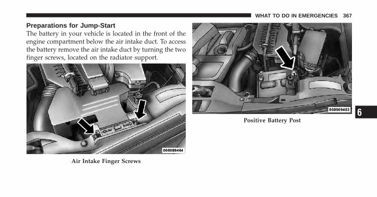
Preparations for Jump-StartThe battery in your vehicle is located in the front of theengine compartment below the air intake duct. To accessthe battery remove the air intake duct by turning the twofinger screws, located on the radiator support.
Air Intake Finger Screws
Positive Battery Post6
WHAT TO DO IN EMERGENCIES 367
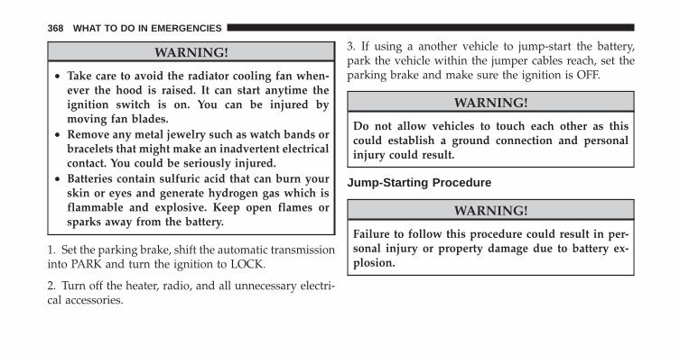
WARNING!
• Take care to avoid the radiator cooling fan when-ever the hood is raised. It can start anytime theignition switch is on. You can be injured bymoving fan blades.
• Remove any metal jewelry such as watch bands orbracelets that might make an inadvertent electricalcontact. You could be seriously injured.
• Batteries contain sulfuric acid that can burn yourskin or eyes and generate hydrogen gas which isflammable and explosive. Keep open flames orsparks away from the battery.
1. Set the parking brake, shift the automatic transmissioninto PARK and turn the ignition to LOCK.
2. Turn off the heater, radio, and all unnecessary electri-cal accessories.
3. If using a another vehicle to jump-start the battery,park the vehicle within the jumper cables reach, set theparking brake and make sure the ignition is OFF.
WARNING!
Do not allow vehicles to touch each other as thiscould establish a ground connection and personalinjury could result.
Jump-Starting Procedure
WARNING!
Failure to follow this procedure could result in per-sonal injury or property damage due to battery ex-plosion.
368 WHAT TO DO IN EMERGENCIES

CAUTION!
Failure to follow these procedures could result indamage to the charging system of the booster vehicleor the discharged vehicle.
1. Connect the positive (+) end of the jumper cable to thepositive (+) post of the discharged vehicle.
2. Connect the opposite end of the positive (+) jumpercable to the positive (+) post of the booster battery.
3. Connect the negative end (-) of the jumper cable to thenegative (-) post of the booster battery.
4. Connect the opposite end of the negative (-) jumpercable to a good engine ground (exposed metal part of thedischarged vehicle’s engine) away from the battery andthe fuel injection system.
WARNING!
Do not connect the cable to the negative post (-) of thedischarged battery. The resulting electrical sparkcould cause the battery to explode and could result inpersonal injury.
5. Start the engine in the vehicle that has the boosterbattery, let the engine idle a few minutes, and then startthe engine in the vehicle with the discharged battery.
Once the engine is started, remove the jumper cables inthe reverse sequence:
6. Disconnect the negative (-) jumper cable from theengine ground of the vehicle with the discharged battery.
7. Disconnect the negative end (-) of the jumper cablefrom the negative (-) post of the booster battery.
6
WHAT TO DO IN EMERGENCIES 369
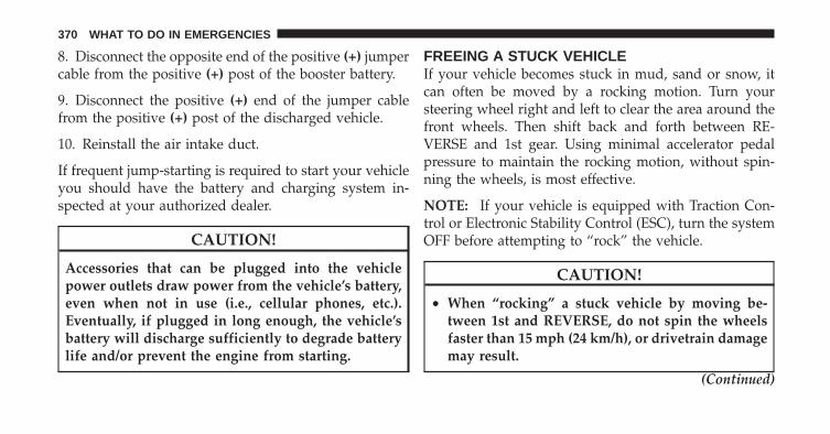
8. Disconnect the opposite end of the positive (+) jumpercable from the positive (+) post of the booster battery.
9. Disconnect the positive (+) end of the jumper cablefrom the positive (+) post of the discharged vehicle.
10. Reinstall the air intake duct.
If frequent jump-starting is required to start your vehicleyou should have the battery and charging system in-spected at your authorized dealer.
CAUTION!
Accessories that can be plugged into the vehiclepower outlets draw power from the vehicle’s battery,even when not in use (i.e., cellular phones, etc.).Eventually, if plugged in long enough, the vehicle’sbattery will discharge sufficiently to degrade batterylife and/or prevent the engine from starting.
FREEING A STUCK VEHICLEIf your vehicle becomes stuck in mud, sand or snow, itcan often be moved by a rocking motion. Turn yoursteering wheel right and left to clear the area around thefront wheels. Then shift back and forth between RE-VERSE and 1st gear. Using minimal accelerator pedalpressure to maintain the rocking motion, without spin-ning the wheels, is most effective.
NOTE: If your vehicle is equipped with Traction Con-trol or Electronic Stability Control (ESC), turn the systemOFF before attempting to “rock” the vehicle.
CAUTION!
• When “rocking” a stuck vehicle by moving be-tween 1st and REVERSE, do not spin the wheelsfaster than 15 mph (24 km/h), or drivetrain damagemay result.
(Continued)
370 WHAT TO DO IN EMERGENCIES
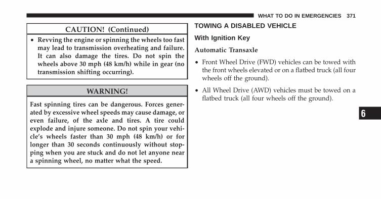
CAUTION! (Continued)• Revving the engine or spinning the wheels too fast
may lead to transmission overheating and failure.It can also damage the tires. Do not spin thewheels above 30 mph (48 km/h) while in gear (notransmission shifting occurring).
WARNING!
Fast spinning tires can be dangerous. Forces gener-ated by excessive wheel speeds may cause damage, oreven failure, of the axle and tires. A tire couldexplode and injure someone. Do not spin your vehi-cle’s wheels faster than 30 mph (48 km/h) or forlonger than 30 seconds continuously without stop-ping when you are stuck and do not let anyone neara spinning wheel, no matter what the speed.
TOWING A DISABLED VEHICLE
With Ignition Key
Automatic Transaxle
• Front Wheel Drive (FWD) vehicles can be towed withthe front wheels elevated or on a flatbed truck (all fourwheels off the ground).
• All Wheel Drive (AWD) vehicles must be towed on aflatbed truck (all four wheels off the ground).
6
WHAT TO DO IN EMERGENCIES 371
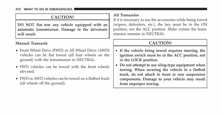
CAUTION!
DO NOT flat tow any vehicle equipped with anautomatic transmission. Damage to the drivetrainwill result.
Manual Transaxle
• Front Wheel Drive (FWD) or All Wheel Drive (AWD)vehicles can be flat towed (all four wheels on theground) with the transmission in NEUTRAL.
• FWD vehicles can be towed with the front wheelselevated.
• FWD or AWD vehicles can be towed on a flatbed truck(all wheels off the ground).
All TransaxlesIf it is necessary to use the accessories while being towed(wipers, defrosters, etc.), the key must be in the ONposition, not the ACC position. Make certain the trans-mission remains in NEUTRAL.
CAUTION!
• If the vehicle being towed requires steering, theignition switch must be in the ACC position, notin the LOCK position.
• Do not attempt to use sling-type equipment whentowing. When securing the vehicle to a flatbedtruck, do not attach to front or rear suspensioncomponents. Damage to your vehicle may resultfrom improper towing.
372 WHAT TO DO IN EMERGENCIES
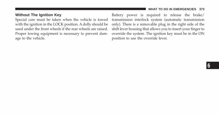
Without The Ignition KeySpecial care must be taken when the vehicle is towedwith the ignition in the LOCK position. A dolly should beused under the front wheels if the rear wheels are raised.Proper towing equipment is necessary to prevent dam-age to the vehicle.
Battery power is required to release the brake/transmission interlock system (automatic transmissiononly). There is a removable plug in the right side of theshift lever housing that allows you to insert your finger tooverride the system. The ignition key must be in the ONposition to use the override lever.
6
WHAT TO DO IN EMERGENCIES 373


MAINTAINING YOUR VEHICLE
CONTENTS
� Engine Compartment — 2.0L . . . . . . . . . . . . . 377
� Engine Compartment — 2.4L . . . . . . . . . . . . . 378
� Onboard Diagnostic System — OBD II . . . . . . 379
▫ Loose Fuel Filler Cap Message . . . . . . . . . . . 379
� Emissions Inspection And MaintenancePrograms . . . . . . . . . . . . . . . . . . . . . . . . . . . . 380
� Replacement Parts . . . . . . . . . . . . . . . . . . . . . 381
� Dealer Service . . . . . . . . . . . . . . . . . . . . . . . . 382
� Maintenance Procedures . . . . . . . . . . . . . . . . . 382
▫ Engine Oil . . . . . . . . . . . . . . . . . . . . . . . . . 383
▫ Engine Oil Filter . . . . . . . . . . . . . . . . . . . . . 386
▫ Engine Air Cleaner Filter . . . . . . . . . . . . . . . 386
▫ Maintenance-Free Battery . . . . . . . . . . . . . . 387
▫ Air Conditioner Maintenance . . . . . . . . . . . . 388
▫ Body Lubrication . . . . . . . . . . . . . . . . . . . . 389
▫ Windshield Wiper Blades . . . . . . . . . . . . . . . 390
▫ Adding Washer Fluid . . . . . . . . . . . . . . . . . 390
7
▫ Exhaust System . . . . . . . . . . . . . . . . . . . . . 391
▫ Cooling System . . . . . . . . . . . . . . . . . . . . . 393
▫ Brake System . . . . . . . . . . . . . . . . . . . . . . . 398
▫ Automatic Transaxle (CVT) – If Equipped . . . 400
▫ Manual Transaxle – If Equipped . . . . . . . . . . 401
▫ Rear Drive Assembly (RDA) – AWD/4WDModels Only . . . . . . . . . . . . . . . . . . . . . . . 402
▫ Power Transfer Unit (PTU) – AWD/4WDModels Only . . . . . . . . . . . . . . . . . . . . . . . 403
▫ Appearance Care And Protection FromCorrosion . . . . . . . . . . . . . . . . . . . . . . . . . . 403
� Fuses . . . . . . . . . . . . . . . . . . . . . . . . . . . . . . 408
▫ Integrated Power Module (IPM) . . . . . . . . . . 408
� Vehicle Storage . . . . . . . . . . . . . . . . . . . . . . . 411
� Replacement Bulbs . . . . . . . . . . . . . . . . . . . . 412
� Bulb Replacement . . . . . . . . . . . . . . . . . . . . . 413
▫ Headlamps . . . . . . . . . . . . . . . . . . . . . . . . 413
▫ Fog Lamps . . . . . . . . . . . . . . . . . . . . . . . . . 415
▫ Tail Lamp, Rear Turn Signal And BackupLamp . . . . . . . . . . . . . . . . . . . . . . . . . . . . . 416
▫ License Lamps . . . . . . . . . . . . . . . . . . . . . . 417
▫ Center High-Mounted Stoplamp . . . . . . . . . 419
▫ Off-Road Lamp . . . . . . . . . . . . . . . . . . . . . 419
� Fluid Capacities . . . . . . . . . . . . . . . . . . . . . . 421
� Fluids, Lubricants, And Genuine Parts . . . . . . . 422
▫ Engine . . . . . . . . . . . . . . . . . . . . . . . . . . . . 422
▫ Chassis . . . . . . . . . . . . . . . . . . . . . . . . . . . 423
376 MAINTAINING YOUR VEHICLE
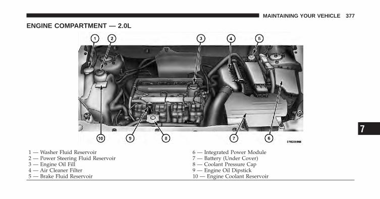
ENGINE COMPARTMENT — 2.0L
1 — Washer Fluid Reservoir 6 — Integrated Power Module2 — Power Steering Fluid Reservoir 7 — Battery (Under Cover)3 — Engine Oil Fill 8 — Coolant Pressure Cap4 — Air Cleaner Filter 9 — Engine Oil Dipstick5 — Brake Fluid Reservoir 10 — Engine Coolant Reservoir
7
MAINTAINING YOUR VEHICLE 377
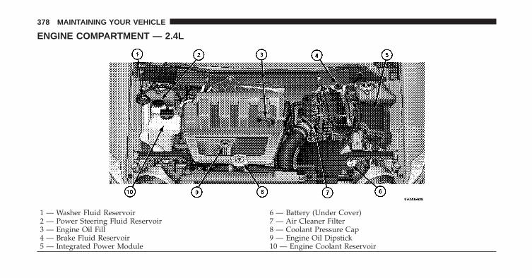
ENGINE COMPARTMENT — 2.4L
1 — Washer Fluid Reservoir 6 — Battery (Under Cover)2 — Power Steering Fluid Reservoir 7 — Air Cleaner Filter3 — Engine Oil Fill 8 — Coolant Pressure Cap4 — Brake Fluid Reservoir 9 — Engine Oil Dipstick5 — Integrated Power Module 10 — Engine Coolant Reservoir
378 MAINTAINING YOUR VEHICLE

ONBOARD DIAGNOSTIC SYSTEM — OBD IIYour vehicle is equipped with a sophisticated OnboardDiagnostic system called OBD II. This system monitorsthe performance of the emissions, engine, and automatictransaxle control systems. When these systems are oper-ating properly, your vehicle will provide excellent per-formance and fuel economy, as well as engine emissionswell within current government regulations.
If any of these systems require service, the OBD II systemwill turn on the “Malfunction Indicator Light (MIL).” Itwill also store diagnostic codes and other information toassist your service technician in making repairs. Al-though your vehicle will usually be drivable and notneed towing, see your authorized dealer for service assoon as possible.
CAUTION!
• Prolonged driving with the MIL on could causefurther damage to the emission control system. Itcould also affect fuel economy and drivability. Thevehicle must be serviced before any emissionstests can be performed.
• If the MIL is flashing while the engine is running,severe catalytic converter damage and power losswill soon occur. Immediate service is required.
Loose Fuel Filler Cap MessageAfter fuel is added, the vehicle diagnostic system candetermine if the fuel filler cap is possibly loose orimproperly installed. A “gASCAP” message will be dis-played in the instrument cluster. Tighten the gas cap untila �clicking� sound is heard. This is an indication that thegas cap is properly tightened. Press the trip odometerRESET button to turn off the message. If the problem
7
MAINTAINING YOUR VEHICLE 379
persists, the message will appear the next time thevehicle is started. This might indicate a damaged cap. Ifthe problem is detected twice in a row, the system willturn on the MIL. Resolving the problem will turn the MILlight off.
EMISSIONS INSPECTION AND MAINTENANCEPROGRAMSIn some localities, it may be a legal requirement to passan inspection of your vehicle’s emissions control system.Failure to pass could prevent vehicle registration.
For states that require an Inspection and Mainte-nance (I/M), this check verifies the “MalfunctionIndicator Light (MIL)” is functioning and is not
on when the engine is running, and that the OBD IIsystem is ready for testing.
Normally, the OBD II system will be ready. The OBD IIsystem may not be ready if your vehicle was recentlyserviced, recently had a dead battery or a battery replace-ment. If the OBD II system should be determined notready for the I/M test, your vehicle may fail the test.
Your vehicle has a simple ignition key-actuated test,which you can use prior to going to the test station. Tocheck if your vehicle’s OBD II system is ready, you mustdo the following:
1. Turn the ignition switch to the ON position, but do notcrank or start the engine.
2. If you crank or start the engine, you will have to startthis test over.
3. As soon as you turn the ignition switch to the ONposition, you will see the MIL symbol come on as part ofa normal bulb check.
380 MAINTAINING YOUR VEHICLE

4. Approximately 15 seconds later, one of two things willhappen:
a. The MIL will flash for about 10 seconds and thenreturn to being fully illuminated until you turn OFFthe ignition or start the engine. This means that yourvehicle’s OBD II system is not ready and you shouldnot proceed to the I/M station.
b. The MIL will not flash at all and will remain fullyilluminated until you turn OFF the ignition or start theengine. This means that your vehicle’s OBD II systemis ready and you can proceed to the I/M station.
If your OBD II system is not ready, you should see yourauthorized dealer or repair facility. If your vehicle wasrecently serviced or had a battery failure or replacement,you may need to do nothing more than drive yourvehicle as you normally would in order for your OBD IIsystem to update. A recheck with the above test routinemay then indicate that the system is now ready.
Regardless of whether your vehicle’s OBD II system isready or not, if the MIL is illuminated during normalvehicle operation you should have your vehicle servicedbefore going to the I/M station. The I/M station can failyour vehicle because the MIL is on with the enginerunning.
REPLACEMENT PARTSUse of genuine MOPAR� parts for normal/scheduledmaintenance and repairs is highly recommended to en-sure the designed performance. Damage or failurescaused by the use of non-MOPAR� parts for maintenanceand repairs will not be covered by the manufacturer’swarranty. 7
MAINTAINING YOUR VEHICLE 381

DEALER SERVICEYour authorized dealer has the qualified service person-nel, special tools, and equipment to perform all serviceoperations in an expert manner. Service Manuals areavailable which include detailed service information foryour vehicle. Refer to these manuals before attemptingany procedure yourself.
NOTE: Intentional tampering with emissions controlsystems may void your warranty and could result in civilpenalties being assessed against you.
WARNING!
You can be badly injured working on or around amotor vehicle. Only do service work for which youhave the knowledge and the proper equipment. Ifyou have any doubt about your ability to perform aservice job, take your vehicle to a competent me-chanic.
MAINTENANCE PROCEDURESThe pages that follow contain the required maintenanceservices determined by the engineers who designed yourvehicle.
Besides those maintenance items specified in the fixedmaintenance schedule, there are other components whichmay require servicing or replacement in the future.
CAUTION!
• Failure to properly maintain your vehicle or per-form repairs and service when necessary couldresult in more costly repairs, damage to othercomponents or negatively impact vehicle perfor-mance. Immediately have potential malfunctionsexamined by an authorized Chrysler Group LLCdealership or qualified repair center.
(Continued)
382 MAINTAINING YOUR VEHICLE
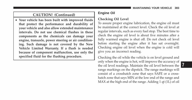
CAUTION! (Continued)• Your vehicle has been built with improved fluids
that protect the performance and durability ofyour vehicle and also allow extended maintenanceintervals. Do not use chemical flushes in thesecomponents as the chemicals can damage yourengine, transaxle, power steering or air condition-ing. Such damage is not covered by the NewVehicle Limited Warranty. If a flush is neededbecause of component malfunction, use only thespecified fluid for the flushing procedure.
Engine Oil
Checking Oil LevelTo assure proper engine lubrication, the engine oil mustbe maintained at the correct level. Check the oil level atregular intervals, such as every fuel stop. The best time tocheck the engine oil level is about five minutes after afully warmed engine is shut off. Do not check oil levelbefore starting the engine after it has sat overnight.Checking engine oil level when the engine is cold willgive you an incorrect reading.
Checking the oil while the vehicle is on level ground andonly when the engine is hot, will improve the accuracy ofthe oil level readings. Maintain the oil level between therange markings on the dipstick. The range markings willconsist of a crosshatch zone that says SAFE or a cross-hatch zone that says MIN at the low end of the range andMAX at the high end of the range. Adding 1 qt (1L) of oil
7
MAINTAINING YOUR VEHICLE 383

when the reading is at the low end of the indicated rangewill result in the oil level at the full end of the indicatorrange.
CAUTION!
Do not overfill the engine. Overfilling the engine asindicated by the range markings, as described above,on the engine oil dipstick will cause oil aeration,which can lead to loss of oil pressure and an increasein oil temperature. This could damage your engine.
Change Engine OilThe oil change indicator system will remind you that it istime to take your vehicle in for scheduled maintenance.Refer to “Maintenance Schedule” for further information.
NOTE: Under no circumstances should oil changeintervals exceed 6,000 miles (10 000 km) or six months,whichever occurs first.
Engine Oil SelectionFor best performance and maximum protection for allengines under all types of operating conditions, themanufacturer recommends engine oils that are API Cer-tified and meet the requirements of Chrysler MaterialStandard MS-6395.
American Petroleum Institute (API) Engine OilIdentification Symbol
This symbol means that the oil hasbeen certified by the AmericanPetroleum Institute (API). Themanufacturer only recommendsAPI Certified engine oils.
384 MAINTAINING YOUR VEHICLE
CAUTION!
Do not use chemical flushes in your engine oil as thechemicals can damage your engine. Such damage isnot covered by the New Vehicle Limited Warranty.
Engine Oil Viscosity (SAE Grade)SAE 5W-20 engine oil is recommended for all operatingtemperatures. This engine oil improves low temperaturestarting and vehicle fuel economy. Your engine oil fillercap also states the recommended engine oil viscositygrade for your engine.
Lubricants which do not have both the engine oil certi-fication mark and the correct SAE viscosity grade num-ber should not be used.
Synthetic Engine OilsYou may use synthetic engine oils provided the recom-mended oil quality requirements are met, and the recom-mended maintenance intervals for oil and filter changesare followed.
Materials Added to Engine OilsThe manufacturer strongly recommends against the ad-dition of any additives (other than leak detection dyes) tothe engine oil. Engine oil is an engineered product and itsperformance may be impaired by supplementaladditives.
Disposing Of Used Engine Oil and Oil FiltersCare should be taken in disposing of used engine oil andoil filtersfrom your vehicle. Used oil and oil filters,indiscriminately discarded, can present a problem to theenvironment. Contact your authorized dealer, service
7
MAINTAINING YOUR VEHICLE 385
station, or governmental agency for advice on how andwhere used oil and oil filters can be safely discarded inyour area.
Engine Oil FilterThe engine oil filter should be replaced at every engineoil change.
Engine Oil Filter SelectionAll of this manufacturer’s engines have a full-flow typedisposable oil filter. Use a filter of this type for replace-ment. The quality of replacement filters varies consider-ably. Only high quality filters should be used to assuremost efficient service. MOPAR� engine oil filters are highquality oil filters and are recommended.
Engine Air Cleaner FilterRefer to “Maintenance Schedule” for further information.
WARNING!
The air cleaner can provide a measure of protectionin the case of engine backfire. Do not remove the aircleaner unless such removal is necessary for repair ormaintenance. Make sure that no one is near theengine compartment before starting the vehicle withthe air cleaner removed. Failure to do so can result inserious personal injury.
Engine Air Cleaner Filter SelectionThe quality of replacement engine air cleaner filters variesconsiderably. Only high quality filters should be used toassure most efficient service. MOPAR� engine air cleanerfilters are a high quality filter and are recommended.
386 MAINTAINING YOUR VEHICLE
Maintenance-Free BatteryThe top of the maintenance-free battery is permanentlysealed. You will never have to add water, nor is periodicmaintenance required.
WARNING!
• Battery fluid is a corrosive acid solution and canburn or even blind you. Do not allow battery fluidto contact your eyes, skin, or clothing. Do not leanover a battery when attaching clamps. If acidsplashes in eyes or on skin, flush the area imme-diately with large amounts of water.
• Battery gas is flammable and explosive. Keepflame or sparks away from the battery. Do not usea booster battery or any other booster source withan output greater than 12 Volts. Do not allow cableclamps to touch each other.
(Continued)
WARNING! (Continued)• Battery posts, terminals, and related accessories
contain lead and lead compounds. Wash handsafter handling.
• The battery in this vehicle has a vent hose thatshould not be disconnected and should only bereplaced with a battery of the same type (vented).
CAUTION!
• It is essential when replacing the cables on thebattery that the positive cable is attached to thepositive post and the negative cable is attached tothe negative post. Battery posts are marked posi-tive (+) and negative (-) and are identified on thebattery case. Cable clamps should be tight on theterminal posts and free of corrosion.
(Continued)
7
MAINTAINING YOUR VEHICLE 387
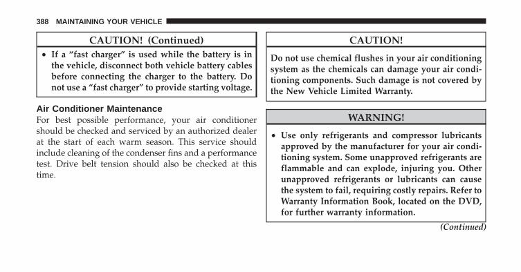
CAUTION! (Continued)• If a “fast charger” is used while the battery is in
the vehicle, disconnect both vehicle battery cablesbefore connecting the charger to the battery. Donot use a “fast charger” to provide starting voltage.
Air Conditioner MaintenanceFor best possible performance, your air conditionershould be checked and serviced by an authorized dealerat the start of each warm season. This service shouldinclude cleaning of the condenser fins and a performancetest. Drive belt tension should also be checked at thistime.
CAUTION!
Do not use chemical flushes in your air conditioningsystem as the chemicals can damage your air condi-tioning components. Such damage is not covered bythe New Vehicle Limited Warranty.
WARNING!
• Use only refrigerants and compressor lubricantsapproved by the manufacturer for your air condi-tioning system. Some unapproved refrigerants areflammable and can explode, injuring you. Otherunapproved refrigerants or lubricants can causethe system to fail, requiring costly repairs. Refer toWarranty Information Book, located on the DVD,for further warranty information.
(Continued)
388 MAINTAINING YOUR VEHICLE

WARNING! (Continued)• The air conditioning system contains refrigerant
under high pressure. To avoid risk of personalinjury or damage to the system, adding refrigerantor any repair requiring lines to be disconnectedshould be done by an experienced repairman.
Refrigerant Recovery And RecyclingR-134a air conditioning refrigerant is a hydrofluoro-carbon (HFC) that is endorsed by the EnvironmentalProtection Agency and is an ozone-saving product. How-ever, the manufacturer recommends that air conditioningservice be performed by authorized dealers or otherservice facilities using recovery and recycling equipment.
NOTE: Use only manufacturer approved A/C systemsealers, stop leak products, seal conditioners, compressoroil, or refrigerants.
Body LubricationLocks and all body pivot points, including such items asseat tracks, door hinge pivot points and rollers, liftgate,tailgate, sliding doors and hood hinges, should be lubri-cated periodically with a lithium based grease, such asMOPAR� Spray White Lube or equivalent to assurequiet, easy operation and to protect against rust andwear. Prior to the application of any lubricant, the partsconcerned should be wiped clean to remove dust andgrit; after lubricating excess oil and grease should beremoved. Particular attention should also be given tohood latching components to ensure proper function.When performing other underhood services, the hoodlatch, release mechanism and safety catch should becleaned and lubricated.
The external lock cylinders should be lubricated twice ayear, preferably in the Fall and Spring. Apply a small
7
MAINTAINING YOUR VEHICLE 389
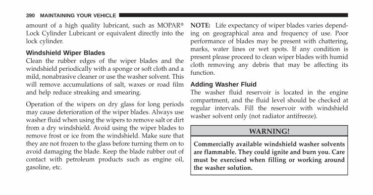
amount of a high quality lubricant, such as MOPAR�Lock Cylinder Lubricant or equivalent directly into thelock cylinder.
Windshield Wiper BladesClean the rubber edges of the wiper blades and thewindshield periodically with a sponge or soft cloth and amild, nonabrasive cleaner or use the washer solvent. Thiswill remove accumulations of salt, waxes or road filmand help reduce streaking and smearing.
Operation of the wipers on dry glass for long periodsmay cause deterioration of the wiper blades. Always usewasher fluid when using the wipers to remove salt or dirtfrom a dry windshield. Avoid using the wiper blades toremove frost or ice from the windshield. Make sure thatthey are not frozen to the glass before turning them on toavoid damaging the blade. Keep the blade rubber out ofcontact with petroleum products such as engine oil,gasoline, etc.
NOTE: Life expectancy of wiper blades varies depend-ing on geographical area and frequency of use. Poorperformance of blades may be present with chattering,marks, water lines or wet spots. If any condition ispresent please proceed to clean wiper blades with humidcloth removing any debris that may be affecting itsfunction.
Adding Washer FluidThe washer fluid reservoir is located in the enginecompartment, and the fluid level should be checked atregular intervals. Fill the reservoir with windshieldwasher solvent only (not radiator antifreeze).
WARNING!
Commercially available windshield washer solventsare flammable. They could ignite and burn you. Caremust be exercised when filling or working aroundthe washer solution.
390 MAINTAINING YOUR VEHICLE

Exhaust SystemThe best protection against carbon monoxide entry intothe vehicle body is a properly maintained engine exhaustsystem.
If you notice a change in the sound of the exhaust system,or if exhaust fumes can be detected inside the vehicle orwhen the underside or rear of the vehicle is damaged,have a competent technician inspect the complete ex-haust system and adjacent body areas for broken, dam-aged, deteriorated, or mispositioned parts. Open seamsor loose connections could permit exhaust fumes to seepinto the passenger compartment. In addition, inspect theexhaust system each time the vehicle is raised for an oilchange or lubrication. Replace as required.
WARNING!
Exhaust gases can injure or kill. They contain carbonmonoxide (CO) which is colorless and odorless.Breathing it can make you unconscious and caneventually poison you. To avoid breathing CO, referto “Safety Tips/Exhaust Gas” in “Things To KnowBefore Starting Your Vehicle” for further informa-tion.
CAUTION!
The catalytic converter requires the use of unleadedfuel only. Leaded gasoline will destroy the effective-ness of the catalyst as an emissions control deviceand may seriously reduce engine performance andcause serious damage to the engine.
7
MAINTAINING YOUR VEHICLE 391
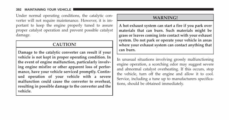
Under normal operating conditions, the catalytic con-verter will not require maintenance. However, it is im-portant to keep the engine properly tuned to assureproper catalyst operation and prevent possible catalystdamage.
CAUTION!
Damage to the catalytic converter can result if yourvehicle is not kept in proper operating condition. Inthe event of engine malfunction, particularly involv-ing engine misfire or other apparent loss of perfor-mance, have your vehicle serviced promptly. Contin-ued operation of your vehicle with a severemalfunction could cause the converter to overheat,resulting in possible damage to the converter and thevehicle.
WARNING!
A hot exhaust system can start a fire if you park overmaterials that can burn. Such materials might begrass or leaves coming into contact with your exhaustsystem. Do not park or operate your vehicle in areaswhere your exhaust system can contact anything thatcan burn.
In unusual situations involving grossly malfunctioningengine operation, a scorching odor may suggest severeand abnormal catalyst overheating. If this occurs, stopthe vehicle, turn off the engine and allow it to cool.Service, including a tune up to manufacturers specifica-tions, should be obtained immediately.
392 MAINTAINING YOUR VEHICLE
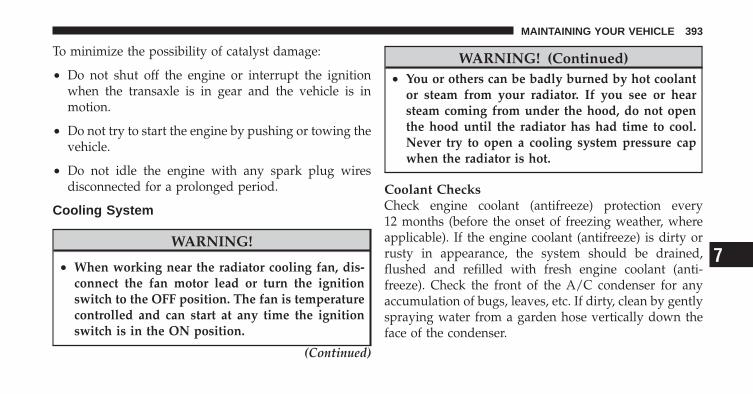
To minimize the possibility of catalyst damage:
• Do not shut off the engine or interrupt the ignitionwhen the transaxle is in gear and the vehicle is inmotion.
• Do not try to start the engine by pushing or towing thevehicle.
• Do not idle the engine with any spark plug wiresdisconnected for a prolonged period.
Cooling System
WARNING!
• When working near the radiator cooling fan, dis-connect the fan motor lead or turn the ignitionswitch to the OFF position. The fan is temperaturecontrolled and can start at any time the ignitionswitch is in the ON position.
(Continued)
WARNING! (Continued)• You or others can be badly burned by hot coolant
or steam from your radiator. If you see or hearsteam coming from under the hood, do not openthe hood until the radiator has had time to cool.Never try to open a cooling system pressure capwhen the radiator is hot.
Coolant ChecksCheck engine coolant (antifreeze) protection every12 months (before the onset of freezing weather, whereapplicable). If the engine coolant (antifreeze) is dirty orrusty in appearance, the system should be drained,flushed and refilled with fresh engine coolant (anti-freeze). Check the front of the A/C condenser for anyaccumulation of bugs, leaves, etc. If dirty, clean by gentlyspraying water from a garden hose vertically down theface of the condenser.
7
MAINTAINING YOUR VEHICLE 393

Check the coolant recovery bottle tubing for brittle rub-ber, cracking, tears, cuts and tightness of the connectionat the bottle and radiator. Inspect the entire system forleaks.
Cooling System – Drain, Flush And RefillRefer to “Maintenance Schedule” for further information.
If the engine coolant (antifreeze) is dirty or contains aconsiderable amount of sediment, clean and flush with areliable cooling system cleaner. Follow with a thoroughrinsing to remove all deposits and chemicals. Properlydispose of old engine coolant (antifreeze).
Selection Of CoolantRefer to “Fluids, Lubricants, and Genuine Parts” in“Maintaining Your Vehicle” for further information.
CAUTION!
• Mixing of engine coolant (antifreeze) other thanspecified Hybrid Organic Additive Technology(HOAT) engine coolant (antifreeze), may result inengine damage and may decrease corrosion pro-tection. If a non-HOAT engine coolant (antifreeze)is introduced into the cooling system in an emer-gency, it should be replaced with the specifiedengine coolant (antifreeze) as soon as possible.
• Do not use water alone or alcohol based enginecoolant (antifreeze) products. Do not use addi-tional rust inhibitors or antirust products, as theymay not be compatible with the radiator enginecoolant and may plug the radiator.
(Continued)
394 MAINTAINING YOUR VEHICLE

CAUTION! (Continued)• This vehicle has not been designed for use with
Propylene Glycol based engine coolant (anti-freeze). Use of Propylene Glycol based enginecoolant (antifreeze) is not recommended.
Adding CoolantYour vehicle has been built with an improved enginecoolant (antifreeze) that allows extended maintenanceintervals. This engine coolant (antifreeze) can be used upto five years or 102,000 miles (170 000 km) beforereplacement. To prevent reducing this extended mainte-nance period, it is important that you use the sameengine coolant (antifreeze) throughout the life of yourvehicle. Please review these recommendations for usingHybrid Organic Additive Technology (HOAT) enginecoolant (antifreeze).
When adding engine coolant (antifreeze), a minimumsolution of 50% recommended MOPAR� Antifreeze/Coolant 5 Year/100,000 Mile Formula HOAT (HybridOrganic Additive Technology), or equivalent, in watershould be used. Use higher concentrations (not to exceed70%) if temperatures below �34°F (�37°C) are antici-pated.
Use only high purity water such as distilled or deionizedwater when mixing the water/engine coolant (antifreeze)solution. The use of lower quality water will reduce theamount of corrosion protection in the engine coolingsystem.
Please note that it is the owner’s responsibility to main-tain the proper level of protection against freezing ac-cording to the temperatures occurring in the area wherethe vehicle is operated.
7
MAINTAINING YOUR VEHICLE 395
NOTE: Mixing engine coolant (antifreeze) types willdecrease the life of the engine coolant (antifreeze) andwill require more frequent coolant changes.
Cooling System Pressure CapThe cap must be fully tightened to prevent loss of enginecoolant (antifreeze) and to ensure that engine coolant(antifreeze) will return to the radiator from the coolantrecovery bottle.
The cap should be inspected and cleaned if there is anyaccumulation of foreign material on the sealing surfaces.
WARNING!
• The warning words “DO NOT OPEN HOT” onthe cooling system pressure cap are a safety pre-caution. Never add engine coolant (antifreeze)when the engine is overheated. Do not loosen orremove the cap to cool an overheated engine. Heatcauses pressure to build up in the cooling system.To prevent scalding or injury, do not remove thepressure cap while the system is hot or underpressure.
• Do not use a pressure cap other than the onespecified for your vehicle. Personal injury or en-gine damage may result.
Disposal Of Used Engine CoolantUsed ethylene glycol-based engine coolant (antifreeze) isa regulated substance requiring proper disposal. Checkwith your local authorities to determine the disposal
396 MAINTAINING YOUR VEHICLE

rules for your community. To prevent ingestion by ani-mals or children do not store ethylene glycol-basedengine coolant (antifreeze) in open containers or allow itto remain in puddles on the ground. If ingested by a childor pet, seek emergency assistance immediately. Clean upany ground spills immediately.
Coolant LevelThe coolant bottle provides a quick visual method fordetermining that the coolant level is adequate. With theengine idling and warm to normal operating tempera-ture, the level of the engine coolant (antifreeze) in thebottle should be between the “ADD” and “FULL” linesshown on the bottle.
The radiator normally remains completely full, so there isno need to remove the radiator cap unless checking forthe coolant freeze point or replacing the engine coolant(antifreeze). Advise your service attendant of this. As
long as the engine operating temperature is satisfactory,the coolant bottle need only be checked once a month.
When additional engine coolant (antifreeze) is needed tomaintain the proper level, it should be added to thecoolant bottle. Do not overfill.
Points to Remember
NOTE: When the vehicle is stopped after a few miles/kilometers of operation, you may observe vapor comingfrom the front of the engine compartment. This is nor-mally a result of moisture from rain, snow, or highhumidity accumulating on the radiator and being vapor-ized when the thermostat opens, allowing hot enginecoolant (antifreeze) to enter the radiator.
If an examination of your engine compartment shows noevidence of radiator or hose leaks, the vehicle may besafely driven. The vapor will soon dissipate.
• Do not overfill the coolant recovery bottle.
7
MAINTAINING YOUR VEHICLE 397

• Check the coolant freeze point in the radiator and inthe coolant recovery bottle. If engine coolant (anti-freeze) needs to be added, the contents of the coolantrecovery bottle must also be protected against freezing.
• If frequent engine coolant (antifreeze) additions arerequired, or if the level in the coolant recovery bottledoes not drop when the engine cools, the coolingsystem should be pressure tested for leaks.
• Maintain engine coolant (antifreeze) concentration at50% HOAT engine coolant (antifreeze) (minimum)and distilled water for proper corrosion protection ofyour engine which contains aluminum components.
• Make sure that the radiator and coolant recoverybottle overflow hoses are not kinked or obstructed.
• Keep the front of the radiator clean. If your vehicle isequipped with air conditioning, keep the front of thecondenser clean.
• Do not change the thermostat for Summer or Winteroperation. If replacement is ever necessary, installONLY the correct type thermostat. Other designs mayresult in unsatisfactory engine coolant (antifreeze) per-formance, poor gas mileage, and increased emissions.
Brake SystemIn order to assure brake system performance, all brakesystem components should be inspected periodically.Refer to “Maintenance Schedule” for further information.
WARNING!
Riding the brakes can lead to brake failure andpossibly an accident. Driving with your foot restingor riding on the brake pedal can result in abnormallyhigh brake temperatures, excessive lining wear, andpossible brake damage. You would not have your fullbraking capacity in an emergency.
398 MAINTAINING YOUR VEHICLE
Brake Master CylinderThe fluid level in the master cylinder should be checkedwhen performing under hood services, or immediately ifthe brake system warning light is on.
Be sure to clean the top of the master cylinder area beforeremoving the cap. If necessary, add fluid to bring thefluid level up to the requirements described on the brakefluid reservoir. Fluid level can be expected to fall as thebrake pads wear. The brake fluid level should be checkedwhen the pads are replaced. However, low fluid levelmay be caused by a leak and a checkup may be needed.
NOTE: If your vehicle is equipped with a manualtransaxle , the brake fluid reservoir supplies fluid to boththe brake system and the clutch release system. The twosystems are separated in the reservoir, and a leak in onesystem will not affect the other system. The manualtransaxle clutch release system should not require fluidreplacement during the life of the vehicle. If the brake
fluid reservoir is low and the brake system does notindicate any leaks or other problems, it may be a result ofa leak in the hydraulic clutch release system. See yourlocal authorized dealer for service.
Use only manufacturer’s recommended brake fluid. Re-fer to “Fluids, Lubricants, and Genuine Parts” in “Main-taining Your Vehicle” for further information.
WARNING!
• Use only manufacturer’s recommended brake fluid.Refer to “Fluids, Lubricants, and Genuine Parts” in“Maintaining Your Vehicle” for further informa-tion. Using the wrong type of brake fluid canseverely damage your brake system and/or impairits performance. The proper type of brake fluid foryour vehicle is also labeled on the original factoryinstalled hydraulic master cylinder reservoir.
(Continued)
7
MAINTAINING YOUR VEHICLE 399

WARNING! (Continued)• To avoid contamination from foreign matter or
moisture, use only new brake fluid or fluid thathas been in a tightly closed container. Keep themaster cylinder reservoir cap secured at all times.Brake fluid in a open container absorbs moisturefrom the air resulting in a lower boiling point.This may cause it to boil unexpectedly during hardor prolonged braking, resulting in sudden brakefailure. This could result in a accident.
• Overfilling the brake fluid reservoir can result inspilling brake fluid on hot engine parts, causingthe brake fluid to catch fire. Brake fluid can alsodamage painted and vinyl surfaces, care should betaken to avoid its contact with these surfaces.
(Continued)
WARNING! (Continued)• Do not allow petroleum based fluid to contami-
nate the brake fluid. Brake seal components couldbe damaged, causing partial or complete brakefailure. This could result in an accident.
CAUTION!
Use of improper brake fluids will affect overallclutch system performance. Improper brake fluidsmay damage the clutch system resulting in loss ofclutch function and the ability to shift the transaxle.
Automatic Transaxle (CVT) – If Equipped
Selection Of LubricantIt is important that the proper lubricant is used in thetransaxle to assure optimum transaxle performance. Useonly the manufacturer’s recommended transmission
400 MAINTAINING YOUR VEHICLE
fluid which has been formulated with special metal tometal friction coefficient additives to provide the propersteel belt traction on the drive and driven pulleys. Referto “Fluids, Lubricants, and Genuine Parts” in “Maintain-ing Your Vehicle” for further information.
CAUTION!
Using a transmission fluid other than the manufac-turer’s recommended fluid will cause belt slip andresult in a complete transaxle failure! Refer to “Flu-ids, Lubricants, and Genuine Parts” in “MaintainingYour Vehicle” for further information.
Fluid Level CheckThe fluid level in the automatic transaxle should bechecked only by a trained technician.
Fluid And Filter ChangesRefer to “Maintenance Schedule” for further information.
Special AdditivesDo not add any materials (other than leak detection dyes)to Continuously Variable Transaxle (CVT) Fluid(CVTF+4�). CVTF+4� is an engineered product and itsperformance may be impaired by supplemental addi-tives.
CAUTION!
Do not use chemical flushes in your transaxle as thechemicals can damage your transaxle components.Such damage is not covered by the New VehicleLimited Warranty.
Manual Transaxle – If Equipped
Lubricant SelectionUse only the manufacturers recommended transmissionfluid. Refer to “Fluids, Lubricants, and Genuine Parts” in“Maintaining Your Vehicle” for further information.
7
MAINTAINING YOUR VEHICLE 401
Fluid Level CheckCheck the fluid level by removing the fill plug. The fluidlevel should be between the bottom of the fill hole and apoint not more than 3/16 in (4.7 mm) below the bottomof the hole.
Add fluid, if necessary, to maintain the proper level.
Frequency Of Fluid ChangeUnder normal operating conditions, the fluid installed atthe factory will give satisfactory lubrication for the life ofthe vehicle. Fluid changes are not necessary unless lubri-cant has become contaminated with water.
NOTE: If contaminated with water, the fluid should bechanged immediately.
Rear Drive Assembly (RDA) – AWD/4WD ModelsOnly
Lubricant SelectionUse only the manufacturer’s recommended fluid. Referto “Fluids, Lubricants, and Genuine Parts” in “Maintain-ing Your Vehicle” for further information.
Fluid Level CheckVisually inspect the unit at each oil change for leakage. Ifleakage is detected, check the fluid level by removing thefill plug. The fluid level should be maintained betweenthe bottom of the fill hole to 1/8 in (4 mm) below the fillhole.
Add fluid, if necessary, to maintain the proper level.
Frequency Of Fluid ChangeRefer to “Maintenance Schedule” for further information.
402 MAINTAINING YOUR VEHICLE
Power Transfer Unit (PTU) – AWD/4WD ModelsOnly
Lubricant SelectionUse only the manufacturer’s recommended fluid. Referto “Fluids, Lubricants, and Genuine Parts” in “Maintain-ing Your Vehicle” for further information.
Fluid Level CheckVisually inspected the unit at each oil change for leakage.If leakage is detected, Check the fluid level by removingthe fill plug. The fluid level should be maintained be-tween the bottom of the fill hole to 1/8 in (4 mm) belowthe fill hole.
Add fluid, if necessary, to maintain the proper level.
Frequency Of Fluid ChangeRefer to “Maintenance Schedule” for further information.
Appearance Care and Protection from Corrosion
Protection of Body and Paint from CorrosionVehicle body care requirements vary according to geo-graphic locations and usage. Chemicals that make roadspassable in snow and ice and those that are sprayed ontrees and road surfaces during other seasons, are highlycorrosive to the metal in your vehicle. Outside parking,which exposes your vehicle to airborne contaminants,road surfaces on which the vehicle is operated, extremehot or cold weather and other extreme conditions willhave an adverse effect on paint, metal trim, and under-body protection.
The following maintenance recommendations will enableyou to obtain maximum benefit from the corrosionresistance built into your vehicle.
What Causes Corrosion?Corrosion is the result of deterioration or removal ofpaint and protective coatings from your vehicle.
7
MAINTAINING YOUR VEHICLE 403
The most common causes of corrosion are:
• Road salt, dirt and moisture accumulation.
• Stone and gravel impact.
• Insects, tree sap and tar.
• Salt in the air near sea coast localities.
• Atmospheric fallout/industrial pollutants.
Washing
• Wash your vehicle regularly. Always wash your ve-hicle in the shade using MOPAR� Car Wash or a mildcar wash soap, and rinse the panels completely withclear water.
• If insects, tar or other similar deposits have accumu-lated on your vehicle, use MOPAR� Super Kleen Bugand Tar Remover or equivalent to remove.
• Use a high quality cleaner wax, such as MOPAR�Cleaner Wax to remove road film, stains and to protectyour paint finish. Take care never to scratch the paint.
• Avoid using abrasive compounds and power buffingthat may diminish the gloss or thin out the paintfinish.
CAUTION!
Do not use abrasive or strong cleaning materials suchas steel wool or scouring powder, which will scratchmetal and painted surfaces.
Special Care
• If you drive on salted or dusty roads or if you drivenear the ocean, hose off the undercarriage at least oncea month.
404 MAINTAINING YOUR VEHICLE
• It is important that the drain holes in the lower edgesof the doors, rocker panels and trunk be kept clear andopen.
• If you detect any stone chips or scratches in the paint,touch them up immediately. The cost of such repairs isconsidered the responsibility of the owner.
• If your vehicle is damaged due to an accident orsimilar cause which destroys the paint and protectivecoating, have your vehicle repaired as soon as pos-sible. The cost of such repairs is considered the respon-sibility of the owner.
• If you carry special cargo such as chemicals, fertilizers,de-icer salt, etc., be sure that such materials are wellpackaged and sealed.
• If a lot of driving is done on gravel roads, considermud or stone shields behind each wheel.
• Use MOPAR� Touch Up Paint or equivalent onscratches as soon as possible. Your authorized dealerhas touch up paint to match the color of your vehicle.
Wheel And Wheel Trim CareAll wheels and wheel trim, especially aluminum andchrome-plated wheels, should be cleaned regularly witha mild soap and water to prevent corrosion. To removeheavy soil, use MOPAR� Wheel Cleaner or select anonabrasive, non-acidic cleaner. Do not use scouringpads, steel wool, a bristle brush or metal polishes. OnlyMOPAR� cleaners or equivalent are recommended. Donot use oven cleaner. Avoid automatic car washes thatuse acidic solutions or harsh brushes that may damagethe wheels’ protective finish.
7
MAINTAINING YOUR VEHICLE 405

Stain Repel Fabric Cleaning Procedure –If EquippedStain Repel seats may be cleaned in the following man-ner:
• Remove as much of the stain as possible by blottingwith a clean, dry towel.
• Blot any remaining stain with a clean, damp towel.
• For tough stains, apply MOPAR� Total Clean or a mildsoap solution to a clean, damp cloth and remove thestain. Use a fresh, damp towel to remove soap residue.
• For grease stains, apply MOPAR� Multi-PurposeCleaner or a equivalent high quality cleaner to a clean,damp cloth and remove the stain. Use a fresh, damptowel to remove soap residue.
• Do not use any harsh solvents or any other form ofprotectants on Stain Repel products.
Interior CareUse MOPAR� Total Clean or equivalent to clean fabricupholstery and carpeting.
Use MOPAR� Total Clean or equivalent to clean vinylupholstery.
MOPAR� Total Clean or equivalent is specifically recom-mended for leather upholstery.
Your leather upholstery can be best preserved by regularcleaning with a damp, soft cloth. Small particles of dirtcan act as an abrasive and damage the leather upholsteryand should be removed promptly with a damp cloth.Stubborn soils can be removed easily with a soft clothand MOPAR� Total Clean or equivalent. Care should betaken to avoid soaking your leather upholstery with anyliquid. Please do not use polishes, oils, cleaning fluids,solvents, detergents, or ammonia based cleaners to cleanyour leather upholstery. Application of a leather condi-tioner is not required to maintain the original condition.
406 MAINTAINING YOUR VEHICLE
WARNING!
Do not use volatile solvents for cleaning purposes.Many are potentially flammable, and if used inclosed areas, they may cause respiratory harm.
Cleaning HeadlightsYour vehicle has plastic headlights that are lighter andless susceptible to stone breakage than glass headlights.
Plastic is not as scratch resistant as glass and, therefore,different lens cleaning procedures must be followed.
To minimize the possibility of scratching the lenses andreducing light output, avoid wiping with a dry cloth. Toremove road dirt, wash with a mild soap solution fol-lowed by rinsing.
Do not use abrasive cleaning components, solvents, steelwool or other aggressive material to clean the lenses.
Glass SurfacesAll glass surfaces should be cleaned on a regular basiswith MOPAR� Glass Cleaner or any commercialhousehold-type glass cleaner. Never use an abrasive typecleaner. Use caution when cleaning the inside rear win-dow equipped with electric defrosters or the right rearquarter window equipped with the radio antenna. Donot use scrapers or other sharp instruments which mayscratch the elements. When cleaning the rearview mirror,spray cleaner on the towel or rag that you are using. Donot spray cleaner directly on the mirror.
Instrument Panel CoverThe instrument panel cover has a low glare surface whichminimizes reflections on the windshield. Do not useprotectants or other products which may cause undesir-able reflections. Use soap and warm water to restore thelow glare surface.
7
MAINTAINING YOUR VEHICLE 407
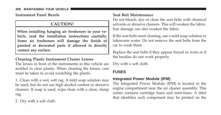
Instrument Panel Bezels
CAUTION!
When installing hanging air fresheners in your ve-hicle, read the installation instructions carefully.Some air fresheners will damage the finish ofpainted or decorated parts if allowed to directlycontact any surface.
Cleaning Plastic Instrument Cluster LensesThe lenses in front of the instruments in this vehicle aremolded in clear plastic. When cleaning the lenses, caremust be taken to avoid scratching the plastic.
1. Clean with a wet, soft rag. A mild soap solution maybe used, but do not use high alcohol content or abrasivecleaners. If soap is used, wipe clean with a clean, damprag.
2. Dry with a soft cloth.
Seat Belt MaintenanceDo not bleach, dye or clean the seat belts with chemicalsolvents or abrasive cleaners. This will weaken the fabric.Sun damage can also weaken the fabric.
If the seat belts need cleaning, use a mild soap solution orlukewarm water. Do not remove the seat belts from thecar to wash them.
Replace the seat belts if they appear frayed or worn or ifthe buckles do not work properly.
Dry with a soft cloth.
FUSES
Integrated Power Module (IPM)The Integrated Power Module (IPM) is located in theengine compartment near the air cleaner assembly. Thiscenter contains cartridge fuses and mini-fuses. A labelthat identifies each component may be printed on the
408 MAINTAINING YOUR VEHICLE
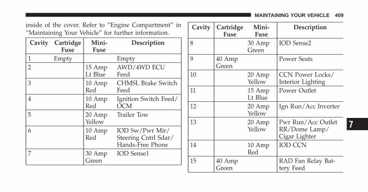
inside of the cover. Refer to “Engine Compartment” in“Maintaining Your Vehicle” for further information.
Cavity CartridgeFuse
Mini-Fuse
Description
1 Empty Empty2 15 Amp
Lt BlueAWD/4WD ECUFeed
3 10 AmpRed
CHMSL Brake SwitchFeed
4 10 AmpRed
Ignition Switch Feed/OCM
5 20 AmpYellow
Trailer Tow
6 10 AmpRed
IOD Sw/Pwr Mir/Steering Cntrl Sdar/Hands-Free Phone
7 30 AmpGreen
IOD Sense1
Cavity CartridgeFuse
Mini-Fuse
Description
8 30 AmpGreen
IOD Sense2
9 40 AmpGreen
Power Seats
10 20 AmpYellow
CCN Power Locks/Interior Lighting
11 15 AmpLt Blue
Power Outlet
12 20 AmpYellow
Ign Run/Acc Inverter
13 20 AmpYellow
Pwr Run/Acc OutletRR/Dome Lamp/Cigar Lighter
14 10 AmpRed
IOD CCN
15 40 AmpGreen
RAD Fan Relay Bat-tery Feed
7
MAINTAINING YOUR VEHICLE 409
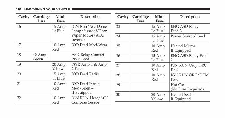
Cavity CartridgeFuse
Mini-Fuse
Description
16 15 AmpLt Blue
IGN Run/Acc DomeLamp/Sunroof/RearWiper Motor/ACCInverter
17 10 AmpRed
IOD Feed Mod-Wcm
18 40 AmpGreen
ASD Relay ContactPWR Feed
19 20 AmpYellow
PWR Amp 1 & Amp2 Feed
20 15 AmpLt Blue
IOD Feed Radio
21 10 AmpRed
IOD Feed IntrusMod/Siren –If Equipped
22 10 AmpRed
IGN RUN Heat/AC/Compass Sensor
Cavity CartridgeFuse
Mini-Fuse
Description
23 15 AmpLt Blue
ENG ASD RelayFeed 3
24 15 AmpLt Blue
Power Sunroof Feed
25 10 AmpRed
Heated Mirror –If Equipped
26 15 AmpLt Blue
ENG ASD Relay Feed2
27 10 AmpRed
IGN RUN Only ORCFeed
28 10 AmpRed
IGN RUN ORC/OCMFeed
29 Hot Car(No Fuse Required)
30 20 AmpYellow
Heated Seat –If Equipped
410 MAINTAINING YOUR VEHICLE

Cavity CartridgeFuse
Mini-Fuse
Description
31 10 AmpRed
Headlamp WasherRelay Control –If Equipped
32 30 AmpPink
ENG ASD ControlFeed 1
33 10 AmpRed
ABS MOD/J1962Conn/PCM
34 30 AmpPink
ABS Valve Feed
35 40 AmpGreen
ABS Pump Feed
36 30 AmpPink
Headlamp/WasherControl/SmartGlass – If Equipped
37 25 AmpNatural
Diesel FuelHeater – If Equipped
CAUTION!
• When installing the IPM cover, it is important toensure the cover is properly positioned and fullylatched. Failure to do so may allow water to getinto the IPM, and possibly result in an electricalsystem failure.
• When replacing a blown fuse, it is important touse only a fuse having the correct amperage rating.The use of a fuse with a rating other than indicatedmay result in a dangerous electrical system over-load. If a properly rated fuse continues to blow, itindicates a problem in the circuit that must becorrected.
VEHICLE STORAGEIf you will not be using your vehicle for more than21 days, you may want to take steps to preserve yourbattery.
7
MAINTAINING YOUR VEHICLE 411

• Disengage the mini-fuse in the Power DistributionCenter labeled IOD (Ignition Off-Draw).
• Disconnect the negative cable from the battery.
REPLACEMENT BULBSAll the inside bulbs are brass or glass wedge base.Aluminum base bulbs are not approved and should notbe used for replacement.
LIGHT BULBS – Interior Bulb NumberFront Header Lamp . . . . . . . . . . . . . . . . . . . . . . T578Center Dome Lamp . . . . . . . . . . . . . . . . . . . . . . T578Rear Cargo Lamp/Flashlight . . . . . . . . . . . . . 8–A35LF
LIGHTS BULBS – Exterior Bulb No.Low Beam/High Beam Headlamp . . . . . . . . . . . . H13Front Park/Turn Signal/Side Marker Lamp . . . 3757KAFront Fog Lamp . . . . . . . . . . . . . . . . . . . . . . PSX24WCenter High Mounted Stop Lamp(CHMSL) . . . . . . . . . . . . . . . . . . . . . . LED AssemblyRear Tail/Stop Lamp . . . . . . . . . . . . . . . . . . . . . 3157Rear Turn Lamp . . . . . . . . . . . . . . . 3157AK or 3157ABackup Lamp . . . . . . . . . . . . . . . . . . . . . W16W (921)License Lamp. . . . . . . . . . . . . . . . . . . . . . . . . . W5WOff-Road Lamp . . . . . . . . . . . . . . . . . . . . . . . . . . H3
412 MAINTAINING YOUR VEHICLE

BULB REPLACEMENT
Headlamps
1. Raise the hood and locate the connector behind theheadlamp.
2. Reach into the engine compartment and pull the redlock out at the green connector.
7
MAINTAINING YOUR VEHICLE 413
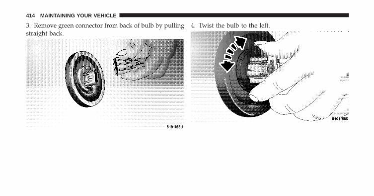
3. Remove green connector from back of bulb by pullingstraight back.
4. Twist the bulb to the left.
414 MAINTAINING YOUR VEHICLE
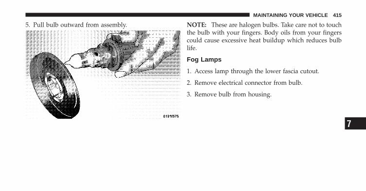
5. Pull bulb outward from assembly. NOTE: These are halogen bulbs. Take care not to touchthe bulb with your fingers. Body oils from your fingerscould cause excessive heat buildup which reduces bulblife.
Fog Lamps
1. Access lamp through the lower fascia cutout.
2. Remove electrical connector from bulb.
3. Remove bulb from housing.
7
MAINTAINING YOUR VEHICLE 415
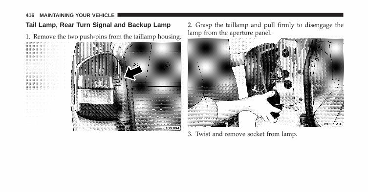
Tail Lamp, Rear Turn Signal and Backup Lamp
1. Remove the two push-pins from the taillamp housing.
2. Grasp the taillamp and pull firmly to disengage thelamp from the aperture panel.
3. Twist and remove socket from lamp.
416 MAINTAINING YOUR VEHICLE

4. Remove bulb from socket and replace. License Lamps
1. Use a screw driver to gently pry against the side of thesnap tab to remove the lamp from the liftgate.
7
MAINTAINING YOUR VEHICLE 417

2. Rotate the socket 1/4 turn counterclockwise. 3. Pull bulb from socket.
418 MAINTAINING YOUR VEHICLE
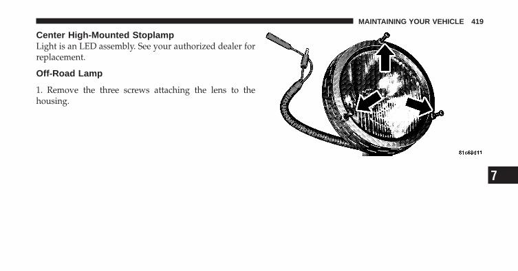
Center High-Mounted StoplampLight is an LED assembly. See your authorized dealer forreplacement.
Off-Road Lamp
1. Remove the three screws attaching the lens to thehousing.
7
MAINTAINING YOUR VEHICLE 419

2. Unlatch the wire clasp securing the bulb into thehousing and rotate it into the position shown.
3. Disconnect the bulb from the lamp harness to replacethe bulb.
420 MAINTAINING YOUR VEHICLE
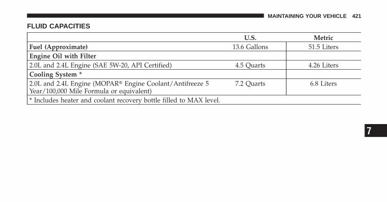
FLUID CAPACITIES
U.S. MetricFuel (Approximate) 13.6 Gallons 51.5 LitersEngine Oil with Filter2.0L and 2.4L Engine (SAE 5W-20, API Certified) 4.5 Quarts 4.26 LitersCooling System *2.0L and 2.4L Engine (MOPAR� Engine Coolant/Antifreeze 5Year/100,000 Mile Formula or equivalent)
7.2 Quarts 6.8 Liters
* Includes heater and coolant recovery bottle filled to MAX level.
7
MAINTAINING YOUR VEHICLE 421
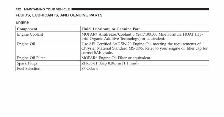
FLUIDS, LUBRICANTS, AND GENUINE PARTS
Engine
Component Fluid, Lubricant, or Genuine PartEngine Coolant MOPAR� Antifreeze/Coolant 5 Year/100,000 Mile Formula HOAT (Hy-
brid Organic Additive Technology) or equivalent.Engine Oil Use API Certified SAE 5W-20 Engine Oil, meeting the requirements of
Chrysler Material Standard MS-6395. Refer to your engine oil filler cap forcorrect SAE grade.
Engine Oil Filter MOPAR� Engine Oil Filter or equivalent.Spark Plugs ZFR5F-11 (Gap 0.043 in [1.1 mm])Fuel Selection 87 Octane
422 MAINTAINING YOUR VEHICLE
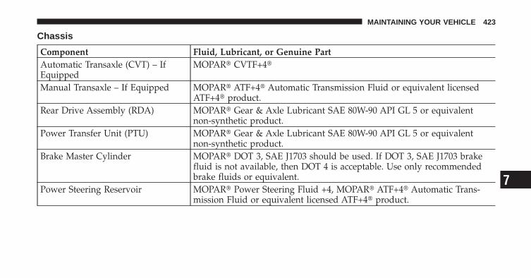
Chassis
Component Fluid, Lubricant, or Genuine PartAutomatic Transaxle (CVT) – IfEquipped
MOPAR� CVTF+4�
Manual Transaxle – If Equipped MOPAR� ATF+4� Automatic Transmission Fluid or equivalent licensedATF+4� product.
Rear Drive Assembly (RDA) MOPAR� Gear & Axle Lubricant SAE 80W-90 API GL 5 or equivalentnon-synthetic product.
Power Transfer Unit (PTU) MOPAR� Gear & Axle Lubricant SAE 80W-90 API GL 5 or equivalentnon-synthetic product.
Brake Master Cylinder MOPAR� DOT 3, SAE J1703 should be used. If DOT 3, SAE J1703 brakefluid is not available, then DOT 4 is acceptable. Use only recommendedbrake fluids or equivalent.
Power Steering Reservoir MOPAR� Power Steering Fluid +4, MOPAR� ATF+4� Automatic Trans-mission Fluid or equivalent licensed ATF+4� product.
7
MAINTAINING YOUR VEHICLE 423


MAINTENANCE SCHEDULES
CONTENTS
� Emissions Control System Maintenance . . . . . . 426
� Maintenance Schedule . . . . . . . . . . . . . . . . . . 426
▫ Required Maintenance Intervals . . . . . . . . . . 428
8
MAINTENANCE
SCHEDULES
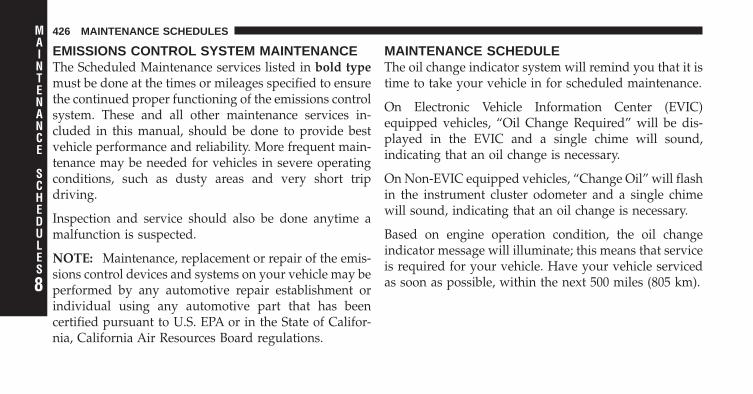
EMISSIONS CONTROL SYSTEM MAINTENANCEThe Scheduled Maintenance services listed in bold typemust be done at the times or mileages specified to ensurethe continued proper functioning of the emissions controlsystem. These and all other maintenance services in-cluded in this manual, should be done to provide bestvehicle performance and reliability. More frequent main-tenance may be needed for vehicles in severe operatingconditions, such as dusty areas and very short tripdriving.
Inspection and service should also be done anytime amalfunction is suspected.
NOTE: Maintenance, replacement or repair of the emis-sions control devices and systems on your vehicle may beperformed by any automotive repair establishment orindividual using any automotive part that has beencertified pursuant to U.S. EPA or in the State of Califor-nia, California Air Resources Board regulations.
MAINTENANCE SCHEDULEThe oil change indicator system will remind you that it istime to take your vehicle in for scheduled maintenance.
On Electronic Vehicle Information Center (EVIC)equipped vehicles, “Oil Change Required” will be dis-played in the EVIC and a single chime will sound,indicating that an oil change is necessary.
On Non-EVIC equipped vehicles, “Change Oil” will flashin the instrument cluster odometer and a single chimewill sound, indicating that an oil change is necessary.
Based on engine operation condition, the oil changeindicator message will illuminate; this means that serviceis required for your vehicle. Have your vehicle servicedas soon as possible, within the next 500 miles (805 km).8
MAINTENANCE
SCHEDULES
426 MAINTENANCE SCHEDULES

NOTE:• The oil change indicator message will not monitor the
time since the last oil change. Change your vehicle’soil if it has been six months since your last oil changeand even if the oil change indicator message is NOTilluminated.
• Change your engine oil more often if you drive yourvehicle off-road for an extended period of time.
• Under no circumstances should oil change intervalsexceed 6,000 miles (10 000 km) or six months, which-ever comes first.
Your authorized dealer will reset the oil change indicatormessage after completing the scheduled oil change. If thisscheduled oil change is performed by someone otherthan your authorized dealer, the message can be reset by
referring to the steps described under “Electronic VehicleInformation Center/Engine Oil Change IndicatorSystem/Oil Change Required” in “Understanding YourInstrument Panel” or under “Instrument ClusterDescription/Odometer/Trip Odometer” in “Under-standing Your Instrument Panel” for further information.
At Each Stop for Fuel
• Check the engine oil level about five minutes after afully warmed engine is shut off. Checking the oil levelwhile the vehicle is on level ground will improve theaccuracy of the oil level reading. Add oil only whenthe level is at or below the ADD or MIN mark.
• Check the windshield washer solvent and add ifrequired. 8
MAINTENANCE
SCHEDULES
MAINTENANCE SCHEDULES 427
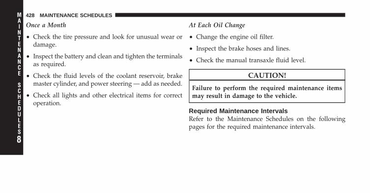
Once a Month
• Check the tire pressure and look for unusual wear ordamage.
• Inspect the battery and clean and tighten the terminalsas required.
• Check the fluid levels of the coolant reservoir, brakemaster cylinder, and power steering — add as needed.
• Check all lights and other electrical items for correctoperation.
At Each Oil Change
• Change the engine oil filter.
• Inspect the brake hoses and lines.
• Check the manual transaxle fluid level.
CAUTION!
Failure to perform the required maintenance itemsmay result in damage to the vehicle.
Required Maintenance IntervalsRefer to the Maintenance Schedules on the followingpages for the required maintenance intervals.
8
MAINTENANCE
SCHEDULES
428 MAINTENANCE SCHEDULES
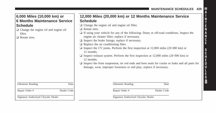
6,000 Miles (10,000 km) or6 Months Maintenance ServiceSchedule❏ Change the engine oil and engine oil
filter.❏ Rotate tires.
Odometer Reading Date
Repair Order # Dealer Code
Signature Authorized Chrysler Dealer
12,000 Miles (20,000 km) or 12 Months Maintenance ServiceSchedule❏ Change the engine oil and engine oil filter.❏ Rotate tires.❏ If using your vehicle for any of the following: Dusty or off-road conditions. Inspect the
engine air cleaner filter; replace if necessary.❏ Inspect the brake linings; replace if necessary.❏ Replace the air conditioning filter.❏ Inspect the CV joints. Perform the first inspection at 12,000 miles (20 000 km) or
12 months.❏ Inspect exhaust system. Perform the first inspection at 12,000 miles (20 000 km) or
12 months.❏ Inspect the front suspension, tie rod ends and boot seals for cracks or leaks and all parts for
damage, wear, improper looseness or end play; replace if necessary.
Odometer Reading Date
Repair Order # Dealer Code
Signature Authorized Chrysler Dealer
8
MAINTENANCE
SCHEDULES
MAINTENANCE SCHEDULES 429

18,000 Miles (30,000 km) or18 Months MaintenanceService Schedule❏ Change the engine oil and engine oil
filter.❏ Rotate tires.
Odometer Reading Date
Repair Order # Dealer Code
Signature Authorized Chrysler Dealer
24,000 Miles (40,000 km) or 24 Months Maintenance ServiceSchedule❏ Change the engine oil and engine oil filter.❏ Rotate tires.❏ If using your vehicle for any of the following: Dusty or off-road conditions. Inspect the
engine air cleaner filter; replace if necessary.❏ Inspect the brake linings; replace if necessary.❏ Replace the air conditioning filter.❏ Inspect the CV joints.❏ Inspect exhaust system.❏ Inspect the front suspension, tie rod ends and boot seals for cracks or leaks and all parts for
damage, wear, improper looseness or end play; replace if necessary.
Odometer Reading Date
Repair Order # Dealer Code
Signature Authorized Chrysler Dealer
8
MAINTENANCE
SCHEDULES
430 MAINTENANCE SCHEDULES
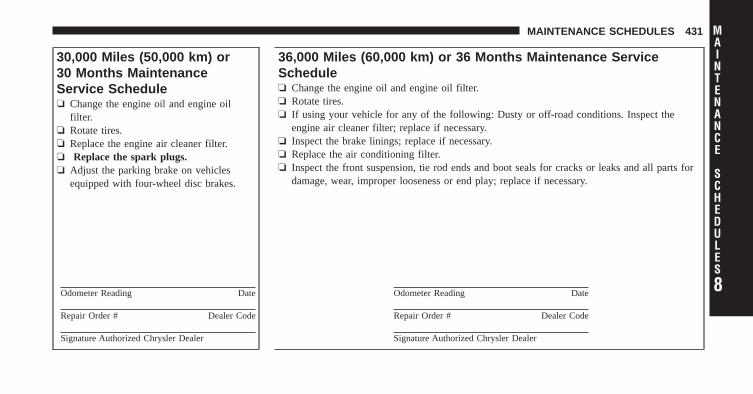
30,000 Miles (50,000 km) or30 Months MaintenanceService Schedule❏ Change the engine oil and engine oil
filter.❏ Rotate tires.❏ Replace the engine air cleaner filter.❏ Replace the spark plugs.❏ Adjust the parking brake on vehicles
equipped with four-wheel disc brakes.
Odometer Reading Date
Repair Order # Dealer Code
Signature Authorized Chrysler Dealer
36,000 Miles (60,000 km) or 36 Months Maintenance ServiceSchedule❏ Change the engine oil and engine oil filter.❏ Rotate tires.❏ If using your vehicle for any of the following: Dusty or off-road conditions. Inspect the
engine air cleaner filter; replace if necessary.❏ Inspect the brake linings; replace if necessary.❏ Replace the air conditioning filter.❏ Inspect the front suspension, tie rod ends and boot seals for cracks or leaks and all parts for
damage, wear, improper looseness or end play; replace if necessary.
Odometer Reading Date
Repair Order # Dealer Code
Signature Authorized Chrysler Dealer
8
MAINTENANCE
SCHEDULES
MAINTENANCE SCHEDULES 431

42,000 Miles (70,000 km) or42 Months MaintenanceService Schedule❏ Change the engine oil and engine oil
filter.❏ Rotate tires.
Odometer Reading Date
Repair Order # Dealer Code
Signature Authorized Chrysler Dealer
48,000 Miles (80,000 km) or 48 Months Maintenance ServiceSchedule❏ Change the engine oil and engine oil filter.❏ Rotate tires.❏ If using your vehicle for any of the following: Dusty or off-road conditions. Inspect the
engine air cleaner filter; replace if necessary.❏ Inspect the brake linings; replace if necessary.❏ Replace the air conditioning filter.❏ Inspect the CV joints.❏ Inspect exhaust system.❏ Inspect the front suspension, tie rod ends and boot seals for cracks or leaks and all parts for
damage, wear, improper looseness or end play; replace if necessary.❏ Change the manual transaxle fluid if using your vehicle for any of the following: trailer
towing, snow plowing, heavy loading, taxi, police, delivery service (commercial service),off-road, desert operation or more than 50% of your driving is at sustained speeds during hotweather, above 90°F (32°C).
Odometer Reading Date
Repair Order # Dealer Code
Signature Authorized Chrysler Dealer
8
MAINTENANCE
SCHEDULES
432 MAINTENANCE SCHEDULES
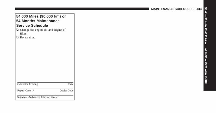
54,000 Miles (90,000 km) or54 Months MaintenanceService Schedule❏ Change the engine oil and engine oil
filter.❏ Rotate tires.
Odometer Reading Date
Repair Order # Dealer Code
Signature Authorized Chrysler Dealer
8
MAINTENANCE
SCHEDULES
MAINTENANCE SCHEDULES 433
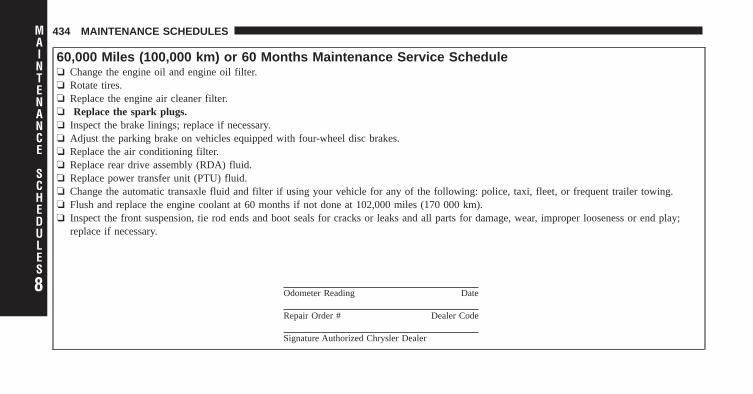
60,000 Miles (100,000 km) or 60 Months Maintenance Service Schedule❏ Change the engine oil and engine oil filter.❏ Rotate tires.❏ Replace the engine air cleaner filter.❏ Replace the spark plugs.❏ Inspect the brake linings; replace if necessary.❏ Adjust the parking brake on vehicles equipped with four-wheel disc brakes.❏ Replace the air conditioning filter.❏ Replace rear drive assembly (RDA) fluid.❏ Replace power transfer unit (PTU) fluid.❏ Change the automatic transaxle fluid and filter if using your vehicle for any of the following: police, taxi, fleet, or frequent trailer towing.❏ Flush and replace the engine coolant at 60 months if not done at 102,000 miles (170 000 km).❏ Inspect the front suspension, tie rod ends and boot seals for cracks or leaks and all parts for damage, wear, improper looseness or end play;
replace if necessary.
Odometer Reading Date
Repair Order # Dealer Code
Signature Authorized Chrysler Dealer
8
MAINTENANCE
SCHEDULES
434 MAINTENANCE SCHEDULES

66,000 Miles (110,000 km) or66 Months MaintenanceService Schedule❏ Change the engine oil and engine oil
filter.❏ Rotate tires.
Odometer Reading Date
Repair Order # Dealer Code
Signature Authorized Chrysler Dealer
72,000 Miles (120,000 km) or 72 Months Maintenance ServiceSchedule❏ Change the engine oil and engine oil filter.❏ Rotate tires.❏ If using your vehicle for any of the following: Dusty or off-road conditions. Inspect the
engine air cleaner filter; replace if necessary.❏ Inspect the brake linings; replace if necessary.❏ Replace the air conditioning filter.❏ Inspect the CV joints.❏ Inspect exhaust system.❏ Inspect the front suspension, tie rod ends and boot seals for cracks or leaks and all parts for
damage, wear, improper looseness or end play; replace if necessary.
Odometer Reading Date
Repair Order # Dealer Code
Signature Authorized Chrysler Dealer
8
MAINTENANCE
SCHEDULES
MAINTENANCE SCHEDULES 435

78,000 Miles (130,000 km) or78 Months MaintenanceService Schedule❏ Change the engine oil and engine oil
filter.❏ Rotate tires.
Odometer Reading Date
Repair Order # Dealer Code
Signature Authorized Chrysler Dealer
84,000 Miles (140,000 km) or 84 Months Maintenance ServiceSchedule❏ Change the engine oil and engine oil filter.❏ Rotate tires.❏ If using your vehicle for any of the following: Dusty or off-road conditions. Inspect the
engine air cleaner filter; replace if necessary.❏ Inspect the brake linings; replace if necessary.❏ Replace the air conditioning filter.❏ Inspect the front suspension, tie rod ends and boot seals for cracks or leaks and all parts for
damage, wear, improper looseness or end play; replace if necessary.
Odometer Reading Date
Repair Order # Dealer Code
Signature Authorized Chrysler Dealer
8
MAINTENANCE
SCHEDULES
436 MAINTENANCE SCHEDULES
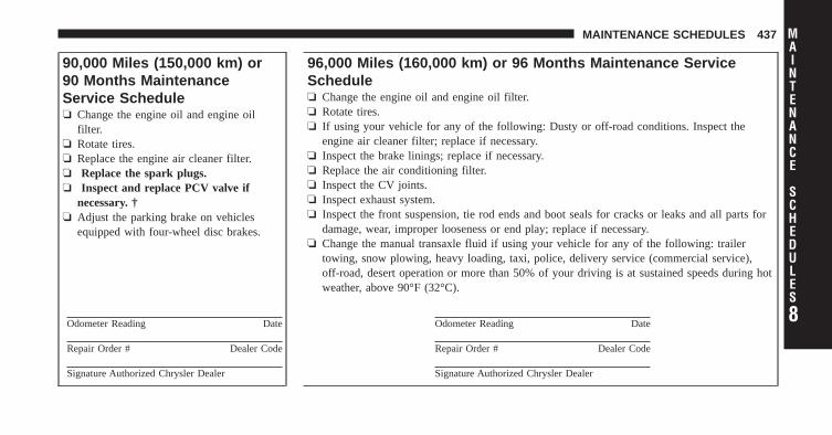
90,000 Miles (150,000 km) or90 Months MaintenanceService Schedule❏ Change the engine oil and engine oil
filter.❏ Rotate tires.❏ Replace the engine air cleaner filter.❏ Replace the spark plugs.❏ Inspect and replace PCV valve if
necessary. †❏ Adjust the parking brake on vehicles
equipped with four-wheel disc brakes.
Odometer Reading Date
Repair Order # Dealer Code
Signature Authorized Chrysler Dealer
96,000 Miles (160,000 km) or 96 Months Maintenance ServiceSchedule❏ Change the engine oil and engine oil filter.❏ Rotate tires.❏ If using your vehicle for any of the following: Dusty or off-road conditions. Inspect the
engine air cleaner filter; replace if necessary.❏ Inspect the brake linings; replace if necessary.❏ Replace the air conditioning filter.❏ Inspect the CV joints.❏ Inspect exhaust system.❏ Inspect the front suspension, tie rod ends and boot seals for cracks or leaks and all parts for
damage, wear, improper looseness or end play; replace if necessary.❏ Change the manual transaxle fluid if using your vehicle for any of the following: trailer
towing, snow plowing, heavy loading, taxi, police, delivery service (commercial service),off-road, desert operation or more than 50% of your driving is at sustained speeds during hotweather, above 90°F (32°C).
Odometer Reading Date
Repair Order # Dealer Code
Signature Authorized Chrysler Dealer
8
MAINTENANCE
SCHEDULES
MAINTENANCE SCHEDULES 437

102,000 Miles (170,000 km) or102 Months MaintenanceService Schedule❏ Change the engine oil and engine oil
filter.❏ Rotate tires.❏ Flush and replace the engine coolant if
not done at 60 months.
Odometer Reading Date
Repair Order # Dealer Code
Signature Authorized Chrysler Dealer
108,000 Miles (180,000 km) or 108 Months Maintenance ServiceSchedule❏ Change the engine oil and engine oil filter.❏ Rotate tires.❏ If using your vehicle for any of the following: Dusty or off-road conditions. Inspect the
engine air cleaner filter; replace if necessary.❏ Inspect the brake linings; replace if necessary.❏ Replace the air conditioning filter.❏ Inspect the front suspension, tie rod ends and boot seals for cracks or leaks and all parts for
damage, wear, improper looseness or end play; replace if necessary.
Odometer Reading Date
Repair Order # Dealer Code
Signature Authorized Chrysler Dealer
8
MAINTENANCE
SCHEDULES
438 MAINTENANCE SCHEDULES
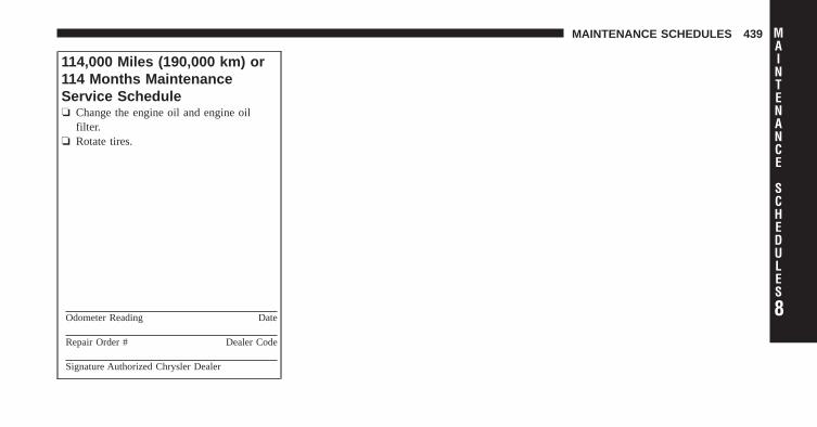
114,000 Miles (190,000 km) or114 Months MaintenanceService Schedule❏ Change the engine oil and engine oil
filter.❏ Rotate tires.
Odometer Reading Date
Repair Order # Dealer Code
Signature Authorized Chrysler Dealer
8
MAINTENANCE
SCHEDULES
MAINTENANCE SCHEDULES 439

120,000 Miles (200,000 km) or 120 Months Maintenance Service Schedule❏ Change the engine oil and engine oil filter.❏ Rotate tires.❏ Replace the engine air cleaner filter.❏ Replace the spark plugs.❏ Inspect the brake linings; replace if necessary.❏ Adjust the parking brake on vehicles equipped with four-wheel disc brakes.❏ Replace the air conditioning filter.❏ Inspect the CV joints.❏ Inspect exhaust system.❏ Inspect the front suspension, tie rod ends and boot seals for cracks or leaks and all parts for damage, wear, improper looseness or end play;
replace if necessary.❏ Replace rear drive assembly (RDA) fluid.❏ Replace power transfer unit (PTU) fluid.❏ Change the automatic transaxle fluid and filter.❏ Replace the accessory drive belt(s).
Odometer Reading Date
Repair Order # Dealer Code
Signature Authorized Chrysler Dealer
8
MAINTENANCE
SCHEDULES
440 MAINTENANCE SCHEDULES

126,000 Miles (210,000 km) or126 Months MaintenanceService Schedule❏ Change the engine oil and engine oil
filter.❏ Rotate tires.
Odometer Reading Date
Repair Order # Dealer Code
Signature Authorized Chrysler Dealer
132,000 Miles (220,000 km) or 132 Months Maintenance ServiceSchedule❏ Change the engine oil and engine oil filter.❏ Rotate tires.❏ If using your vehicle for any of the following: Dusty or off-road conditions. Inspect the
engine air cleaner filter; replace if necessary.❏ Inspect the brake linings; replace if necessary.❏ Replace the air conditioning filter.❏ Inspect the front suspension, tie rod ends and boot seals for cracks or leaks and all parts for
damage, wear, improper looseness or end play; replace if necessary.
Odometer Reading Date
Repair Order # Dealer Code
Signature Authorized Chrysler Dealer
8
MAINTENANCE
SCHEDULES
MAINTENANCE SCHEDULES 441

138,000 Miles (230,000 km) or138 Months MaintenanceService Schedule❏ Change the engine oil and engine oil
filter.❏ Rotate tires.
Odometer Reading Date
Repair Order # Dealer Code
Signature Authorized Chrysler Dealer
144,000 Miles (240,000 km) or 144 Months Maintenance ServiceSchedule❏ Change the engine oil and engine oil filter.❏ Rotate tires.❏ If using your vehicle for any of the following: Dusty or off-road conditions. Inspect the
engine air cleaner filter; replace if necessary.❏ Inspect the brake linings; replace if necessary.❏ Replace the air conditioning filter.❏ Inspect the CV joints.❏ Inspect exhaust system.❏ Inspect the front suspension, tie rod ends and boot seals for cracks or leaks and all parts for
damage, wear, improper looseness or end play; replace if necessary.❏ Change the manual transaxle fluid if using your vehicle for any of the following: trailer
towing, snow plowing, heavy loading, taxi, police, delivery service (commercial service),off-road, desert operation or more than 50% of your driving is at sustained speeds during hotweather, above 90°F (32°C).
Odometer Reading Date
Repair Order # Dealer Code
Signature Authorized Chrysler Dealer
8
MAINTENANCE
SCHEDULES
442 MAINTENANCE SCHEDULES
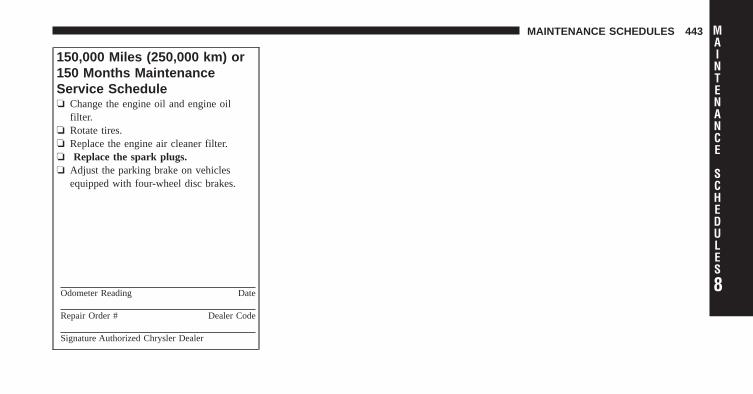
150,000 Miles (250,000 km) or150 Months MaintenanceService Schedule❏ Change the engine oil and engine oil
filter.❏ Rotate tires.❏ Replace the engine air cleaner filter.❏ Replace the spark plugs.❏ Adjust the parking brake on vehicles
equipped with four-wheel disc brakes.
Odometer Reading Date
Repair Order # Dealer Code
Signature Authorized Chrysler Dealer
8
MAINTENANCE
SCHEDULES
MAINTENANCE SCHEDULES 443
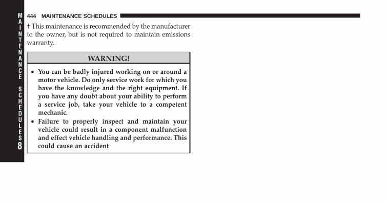
† This maintenance is recommended by the manufacturerto the owner, but is not required to maintain emissionswarranty.
WARNING!
• You can be badly injured working on or around amotor vehicle. Do only service work for which youhave the knowledge and the right equipment. Ifyou have any doubt about your ability to performa service job, take your vehicle to a competentmechanic.
• Failure to properly inspect and maintain yourvehicle could result in a component malfunctionand effect vehicle handling and performance. Thiscould cause an accident8
MAINTENANCE
SCHEDULES
444 MAINTENANCE SCHEDULES

IF YOU NEED CONSUMER ASSISTANCE
CONTENTS
� Suggestions For Obtaining Service For YourVehicle . . . . . . . . . . . . . . . . . . . . . . . . . . . . . . 447
▫ Prepare For The Appointment . . . . . . . . . . . 447
▫ Prepare A List . . . . . . . . . . . . . . . . . . . . . . 447
▫ Be Reasonable With Requests . . . . . . . . . . . . 447
� If You Need Assistance . . . . . . . . . . . . . . . . . 447
▫ Chrysler Group LLC Customer Center . . . . . 448
▫ Chrysler Canada Inc. Customer Center . . . . . 448
▫ In Mexico Contact . . . . . . . . . . . . . . . . . . . . 448
▫ Customer Assistance For The Hearing OrSpeech Impaired (TDD/TTY) . . . . . . . . . . . . 449
▫ Service Contract . . . . . . . . . . . . . . . . . . . . . 449
� Warranty Information (U.S. Vehicles Only) . . . . 450
� MOPAR� Parts . . . . . . . . . . . . . . . . . . . . . . . 450
� Reporting Safety Defects . . . . . . . . . . . . . . . . 450
▫ In The 50 United States AndWashington, D.C. . . . . . . . . . . . . . . . . . . . . 450
▫ In Canada . . . . . . . . . . . . . . . . . . . . . . . . . 451
� Publication Order Forms . . . . . . . . . . . . . . . . 451
9

� Department Of Transportation Uniform TireQuality Grades . . . . . . . . . . . . . . . . . . . . . . . . 453
▫ Treadwear . . . . . . . . . . . . . . . . . . . . . . . . . 453
▫ Traction Grades . . . . . . . . . . . . . . . . . . . . . 453
▫ Temperature Grades . . . . . . . . . . . . . . . . . . 454
446 IF YOU NEED CONSUMER ASSISTANCE
SUGGESTIONS FOR OBTAINING SERVICE FORYOUR VEHICLE
Prepare For The AppointmentIf you’re having warranty work done, be sure to have theright papers with you. Take your warranty folder. Allwork to be performed may not be covered by thewarranty. Discuss additional charges with the servicemanager. Keep a maintenance log of your vehicle’sservice history. This can often provide a clue to thecurrent problem.
Prepare A ListMake a written list of your vehicle’s problems or thespecific work you want done. If you’ve had an accidentor work done that is not on your maintenance log, let theservice advisor know.
Be Reasonable With RequestsIf you list a number of items and you must have yourvehicle by the end of the day, discuss the situation with
the service advisor and list the items in order of priority.At many authorized dealers, you may obtain a rentalvehicle at a minimal daily charge. If you need a rental, itis advisable to make these arrangements when you callfor an appointment.
IF YOU NEED ASSISTANCEThe manufacturer and its authorized dealers are vitallyinterested in your satisfaction. We want you to be happywith our products and services.
Warranty service must be done by an authorized dealer.We strongly recommend that you take the vehicle to anauthorized dealer. They know your vehicle the best, andare most concerned that you get prompt and high qualityservice. The manufacturer’s authorized dealers have thefacilities, factory-trained technicians, special tools, andthe latest information to ensure the vehicle is fixedcorrectly and in a timely manner. 9
IF YOU NEED CONSUMER ASSISTANCE 447

This is why you should always talk to an authorizeddealer’s service manager first. Most matters can be re-solved with this process.
• If for some reason you are still not satisfied, talk to thegeneral manager or owner of the authorized dealer-ship. They want to know if you need assistance.
• If an authorized dealership is unable to resolve theconcern, you may contact the manufacturer’s customercenter.
Any communication to the manufacturer’s customer cen-ter should include the following information:
• Owner’s name and address
• Owner’s telephone number (home and office)
• Authorized dealership name
• Vehicle Identification Number (VIN)
• Vehicle delivery date and mileage
Chrysler Group LLC Customer CenterP.O. Box 21–8004Auburn Hills, MI 48321–8004Phone: (800) 992-1997
Chrysler Canada Inc. Customer CenterP.O. Box 1621Windsor, Ontario N9A 4H6Phone: (800) 465–2001
In Mexico contact:Av. Prolongacion Paseo de la Reforma, 1240Sante Fe C.P. 05109Mexico, D. F.In Mexico City: 5081-7568Outside Mexico City: 1-800-505-1300
448 IF YOU NEED CONSUMER ASSISTANCE
Customer Assistance For The Hearing Or SpeechImpaired (TDD/TTY)To assist customers who have hearing difficulties, themanufacturer has installed special TDD (Telecommuni-cation Devices for the Deaf) equipment at its customercenter. Any hearing or speech impaired customer, whohas access to a TDD or a conventional teletypewriter(TTY) in the United States, can communicate with themanufacturer by dialing 1–800–380–CHRY.Canadian residents with hearing difficulties that requireassistance can use the special needs relay service offeredby Bell Canada. For TTY teletypewriter users, dial 711and for Voice callers, dial 1 800 855-0511 to connect witha Bell Relay Service operator.
Service ContractYou may have purchased a service contract for a vehicleto help protect you from the high cost of unexpectedrepairs after the manufacturer’s New Vehicle LimitedWarranty expires. The manufacturer stands behind only
the manufacturer’s service contracts. If you purchased amanufacturer’s service contract, you will receive PlanProvisions and an Owner Identification Card in the mailwithin three weeks of the vehicle delivery date. If youhave any questions about the service contract, call themanufacturer’s Service Contract National Customer Hot-line at 1-800-521-9922.
The manufacturer will not stand behind any servicecontract that is not the manufacturer’s service contract. Itis not responsible for any service contract other than themanufacturer’s service contract. If you purchased a ser-vice contract that is not a manufacturer’s service contract,and you require service after the manufacturer’s NewVehicle Limited Warranty expires, please refer to thecontract documents, and contact the person listed inthose documents.
We appreciate that you have made a major investmentwhen you purchased the vehicle. An authorized dealer
9
IF YOU NEED CONSUMER ASSISTANCE 449
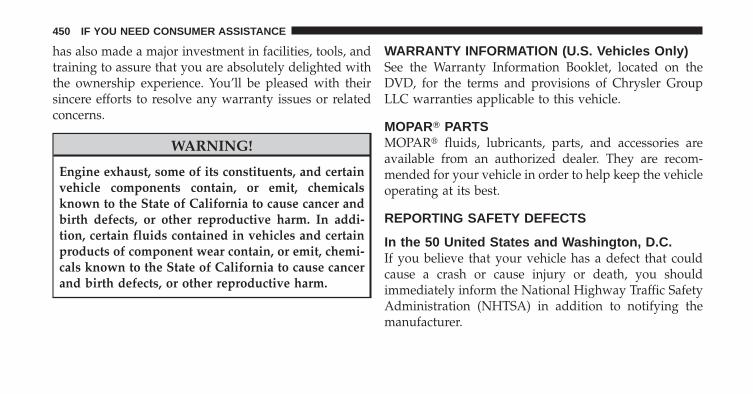
has also made a major investment in facilities, tools, andtraining to assure that you are absolutely delighted withthe ownership experience. You’ll be pleased with theirsincere efforts to resolve any warranty issues or relatedconcerns.
WARNING!
Engine exhaust, some of its constituents, and certainvehicle components contain, or emit, chemicalsknown to the State of California to cause cancer andbirth defects, or other reproductive harm. In addi-tion, certain fluids contained in vehicles and certainproducts of component wear contain, or emit, chemi-cals known to the State of California to cause cancerand birth defects, or other reproductive harm.
WARRANTY INFORMATION (U.S. Vehicles Only)See the Warranty Information Booklet, located on theDVD, for the terms and provisions of Chrysler GroupLLC warranties applicable to this vehicle.
MOPAR� PARTSMOPAR� fluids, lubricants, parts, and accessories areavailable from an authorized dealer. They are recom-mended for your vehicle in order to help keep the vehicleoperating at its best.
REPORTING SAFETY DEFECTS
In the 50 United States and Washington, D.C.If you believe that your vehicle has a defect that couldcause a crash or cause injury or death, you shouldimmediately inform the National Highway Traffic SafetyAdministration (NHTSA) in addition to notifying themanufacturer.
450 IF YOU NEED CONSUMER ASSISTANCE

If NHTSA receives similar complaints, it may open aninvestigation, and if it finds that a safety defect exists ina group of vehicles, it may order a recall and remedycampaign. However, NHTSA cannot become involved inindividual problems between you, your authorizeddealer, and the manufacturer.
To contact NHTSA, you may either call the Auto SafetyHotline toll free at 1–888–327–4236 (TTY: 1–800–424–9153), or go to http://www.safercar.gov; or write to:Administrator, NHTSA, 1200 New Jersey Avenue, SE.,West Building, Washington, D.C. 20590. You can alsoobtain other information about motor vehicle safety fromhttp://www.safercar.gov.
In CanadaIf you believe that your vehicle has a safety defect, youshould contact the Customer Service Department imme-diately. Canadian customers who wish to report a safetydefect to the Canadian government should write to:
Transport Canada, Motor Vehicle Defect Investigationsand Recalls, 2780 Sheffield Road, Ottawa, Ontario K1B3V9.
PUBLICATION ORDER FORMSTo order the following manuals, you may use either thewebsite or the phone numbers listed below. Visa, Mas-tercard, American Express, and Discover orders are ac-cepted. If you prefer mailing your payment, please callfor an order form.
NOTE: A street address is required when orderingmanuals (no P.O. Boxes).
• Service Manuals
These comprehensive Service Manuals provide theinformation that students and professional techniciansneed in diagnosing/troubleshooting, problem solving,maintaining, servicing, and repairing Chrysler GroupLLC vehicles. A complete working knowledge of the
9
IF YOU NEED CONSUMER ASSISTANCE 451

vehicle, system, and/or components is written instraightforward language with illustrations, diagrams,and charts.
• Diagnostic Procedure Manuals
Diagnostic Procedure Manuals are filled with dia-grams, charts and detailed illustrations. These practi-cal manuals make it easy for students and techniciansto find and fix problems on computer-controlled ve-hicle systems and features. They show exactly how tofind and correct problems the first time, using step-by-step troubleshooting and drivability procedures,proven diagnostic tests and a complete list of all toolsand equipment.
• Owner’s Manuals
These Owner’s Manuals have been prepared with theassistance of service and engineering specialists toacquaint you with specific Chrysler Group LLC ve-hicles. Included are starting, operating, emergencyand maintenance procedures as well as specifications,capabilities and safety tips.
Call toll free at:
• 1–800–890–4038 (U.S.)
• 1–800–387–1143 (Canada)
Or
Visit us on the Worldwide Web at:
• www.techauthority.com
452 IF YOU NEED CONSUMER ASSISTANCE

DEPARTMENT OF TRANSPORTATION UNIFORMTIRE QUALITY GRADESThe following tire grading categories were established bythe National Highway Traffic Safety Administration. Thespecific grade rating assigned by the tire’s manufacturerin each category is shown on the sidewall of the tires onyour vehicle.
All passenger car tires must conform to Federal safetyrequirements in addition to these grades.
TreadwearThe Treadwear grade is a comparative rating, based onthe wear rate of the tire when tested under controlledconditions on a specified government test course. Forexample, a tire graded 150 would wear one and one-halftimes as well on the government course as a tire graded100. The relative performance of tires depends upon theactual conditions of their use, however, and may depart
significantly from the norm due to variations in drivinghabits, service practices, and differences in road charac-teristics and climate.
Traction GradesThe Traction grades, from highest to lowest, are AA, A, B,and C. These grades represent the tire’s ability to stop onwet pavement, as measured under controlled conditionson specified government test surfaces of asphalt andconcrete. A tire marked C may have poor traction perfor-mance.
WARNING!
The traction grade assigned to this tire is based onstraight-ahead braking traction tests, and does notinclude acceleration, cornering, hydroplaning, orpeak traction characteristics.
9
IF YOU NEED CONSUMER ASSISTANCE 453
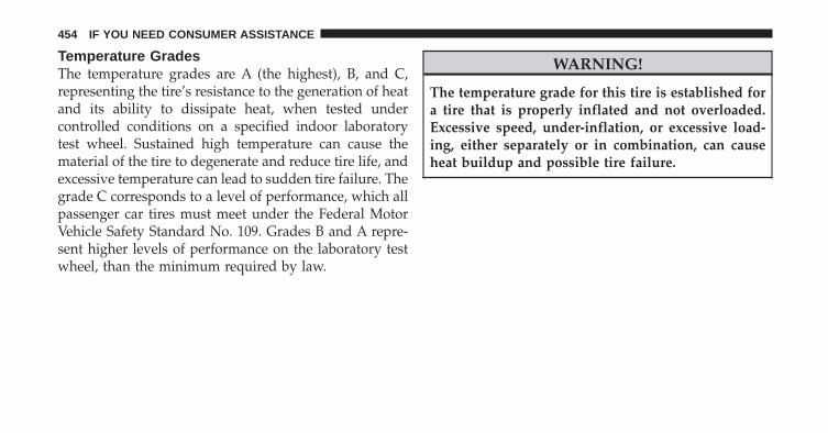
Temperature GradesThe temperature grades are A (the highest), B, and C,representing the tire’s resistance to the generation of heatand its ability to dissipate heat, when tested undercontrolled conditions on a specified indoor laboratorytest wheel. Sustained high temperature can cause thematerial of the tire to degenerate and reduce tire life, andexcessive temperature can lead to sudden tire failure. Thegrade C corresponds to a level of performance, which allpassenger car tires must meet under the Federal MotorVehicle Safety Standard No. 109. Grades B and A repre-sent higher levels of performance on the laboratory testwheel, than the minimum required by law.
WARNING!
The temperature grade for this tire is established fora tire that is properly inflated and not overloaded.Excessive speed, under-inflation, or excessive load-ing, either separately or in combination, can causeheat buildup and possible tire failure.
454 IF YOU NEED CONSUMER ASSISTANCE

INDEX
10
ABS (Anti-Lock Brake System) . . . . . . . . . . . . . . 297Adding Engine Coolant (Antifreeze) . . . . . . . . . . 395Adding Fuel . . . . . . . . . . . . . . . . . . . . . . . . . . . 339Adding Washer Fluid . . . . . . . . . . . . . . . . . . . . . 390Additives, Fuel . . . . . . . . . . . . . . . . . . . . . . . . . 337Air Cleaner, Engine (Engine Air Cleaner Filter) . . . 386Air Conditioner Maintenance . . . . . . . . . . . . . . . 388Air Conditioning . . . . . . . . . . . . . . . . . . . . . . . . 260Air Conditioning Controls . . . . . . . . . . . . . . . . . 260Air Conditioning Filter . . . . . . . . . . . . . . . . . . . . 271Air Conditioning, Operating Tips . . . . . . . . . . . . 272Air Conditioning Refrigerant . . . . . . . . . . . . . 388,389Air Conditioning System . . . . . . . . . . . . . 260,264,388Air Pressure, Tires . . . . . . . . . . . . . . . . . . . . . . . 318Airbag . . . . . . . . . . . . . . . . . . . . . . . . . . . . . . 56,66Airbag Deployment . . . . . . . . . . . . . . . . . . . . . . . 67Airbag Light . . . . . . . . . . . . . . . . . . . 57,64,70,82,184Airbag Maintenance . . . . . . . . . . . . . . . . . . . . . . . 69Airbag, Side . . . . . . . . . . . . . . . . . . . . . . 59,63,65,66
Airbag, Window (Side Curtain) . . . . . . . . . . . 60,63,66Alarm Light . . . . . . . . . . . . . . . . . . . . . . . . . . . 188Alarm System (Security Alarm) . . . . . . . . . . . . . . . 18Alterations/Modifications, Vehicle . . . . . . . . . . . . . 8Antenna, Satellite Radio . . . . . . . . . . . . . . . . . . . 253Antifreeze (Engine Coolant) . . . . . . . . . . . 394,421,422
Capacities . . . . . . . . . . . . . . . . . . . . . . . . . . . 421Disposal . . . . . . . . . . . . . . . . . . . . . . . . . . . . 396
Anti-Lock Brake System (ABS) . . . . . . . . . . . . . . 297Anti-Lock Warning Light . . . . . . . . . . . . . . . . . . 185Anti-Theft Security Alarm (Theft Alarm) . . . . . . . . 18Appearance Care . . . . . . . . . . . . . . . . . . . . . . . . 403Assistance Towing . . . . . . . . . . . . . . . . . . . . . . . 107Automatic Dimming Mirror . . . . . . . . . . . . . . . . . 89Automatic Door Locks . . . . . . . . . . . . . . . . . . . 29,31Automatic Temperature Control (ATC) . . . . . . . . . 264Automatic Transaxle . . . . . . . . . . . 12,277,282,360,400
Fluid Level Check . . . . . . . . . . . . . . . . . . . . . 401Interlock System . . . . . . . . . . . . . . . . . . . . . . . 283
456 INDEX

Overheating . . . . . . . . . . . . . . . . . . . . . . . . . . 360Selection Of Lubricant . . . . . . . . . . . . . . . . . . . 400Shifting . . . . . . . . . . . . . . . . . . . . . . . . . . . . . 284Special Additives . . . . . . . . . . . . . . . . . . . . . . 401
Autostick . . . . . . . . . . . . . . . . . . . . . . . . . . . . . 285
Battery . . . . . . . . . . . . . . . . . . . . . . . . . . . . . . . 387Keyless Transmitter Replacement (RKE) . . . . . . . 24
Belts, Seat . . . . . . . . . . . . . . . . . . . . . . . . . . . . . . 82Body Mechanism Lubrication . . . . . . . . . . . . . . . 389B-Pillar Location . . . . . . . . . . . . . . . . . . . . . . . . 313Brake Assist System . . . . . . . . . . . . . . . . . . . . . . 300Brake Fluid . . . . . . . . . . . . . . . . . . . . . . . . . . . . 423Brake, Parking . . . . . . . . . . . . . . . . . . . . . . . . . . 293Brake System . . . . . . . . . . . . . . . . . . . . . . . . 296,398
Anti-Lock (ABS) . . . . . . . . . . . . . . . . . . . . 297,299Master Cylinder . . . . . . . . . . . . . . . . . . . . . . . 399Parking . . . . . . . . . . . . . . . . . . . . . . . . . . . . . 293Warning Light . . . . . . . . . . . . . . . . . . . . . . . . 186
Brakes . . . . . . . . . . . . . . . . . . . . . . . . . . . . . 296,398Brake/Transmission Interlock . . . . . . . . . . . . . . . 283Break-In Recommendations, New Vehicle . . . . . . . . 80Bulb Replacement . . . . . . . . . . . . . . . . . . . . . 412,413Bulbs, Light . . . . . . . . . . . . . . . . . . . . . . . . . . 83,412
Capacities, Antifreeze (Engine Coolant) . . . . . . . . 421Capacities, Fluid . . . . . . . . . . . . . . . . . . . . . . . . 421Caps, Filler
Fuel . . . . . . . . . . . . . . . . . . . . . . . . . . . . . . . 339Oil (Engine) . . . . . . . . . . . . . . . . . . . . . . . 378,385Power Steering . . . . . . . . . . . . . . . . . . . . . . . . 293
Car Washes . . . . . . . . . . . . . . . . . . . . . . . . . . . . 404Carbon Monoxide Warning . . . . . . . . . . . . . . . 81,339Cargo Area Cover . . . . . . . . . . . . . . . . . . . . . . . 170Cargo Area Features . . . . . . . . . . . . . . . . . . . . . . 169Cargo Compartment
Light . . . . . . . . . . . . . . . . . . . . . . . . . . . . . . . 169Luggage Carrier . . . . . . . . . . . . . . . . . . . . . . . 176 10
INDEX 457
Cargo Light . . . . . . . . . . . . . . . . . . . . . . . . . . . . 169Cargo Load Floor . . . . . . . . . . . . . . . . . . . . . . . . 172Cargo Tie-Downs . . . . . . . . . . . . . . . . . . . . . . . . 173Carrier, Luggage . . . . . . . . . . . . . . . . . . . . . . . . 176Cellular Phone . . . . . . . . . . . . . . . . . . . . . . . . 93,259Center High Mounted Stop Light . . . . . . . . . . . . 419Chains, Tire . . . . . . . . . . . . . . . . . . . . . . . . . . . . 324Changing A Flat Tire . . . . . . . . . . . . . . . . . . . . . 360Chart, Tire Sizing . . . . . . . . . . . . . . . . . . . . . . . . 309Check Engine Light(Malfunction Indicator Light) . . . . . . . . . . . . . . . 380Checking Your Vehicle For Safety . . . . . . . . . . . . . 81Checks, Safety . . . . . . . . . . . . . . . . . . . . . . . . . . . 81Child Restraint . . . . . . . . . . . . . . . . . . . . . . . . . . 72Child Restraint Tether Anchors . . . . . . . . . . . . . . . 76Child Restraint with Automatic Belts . . . . . . . . . . . 75Child Safety Locks . . . . . . . . . . . . . . . . . . . . . . . . 32Child Seat . . . . . . . . . . . . . . . . . . . . . . . . . . . . . . 78Clean Air Gasoline . . . . . . . . . . . . . . . . . . . . . . . 335
CleaningWheels . . . . . . . . . . . . . . . . . . . . . . . . . . . . . 405
Climate Control . . . . . . . . . . . . . . . . . . . . . . . . . 259Clock . . . . . . . . . . . . . . . . . . . . . 208,222,224,227,236Clutch . . . . . . . . . . . . . . . . . . . . . . . . . . . . . . . 399Clutch Fluid . . . . . . . . . . . . . . . . . . . . . . . . . . . 399Coin Holder . . . . . . . . . . . . . . . . . . . . . . . . . . . 168Compact Disc (CD) Maintenance . . . . . . . . . . . . . 258Compact Spare Tire . . . . . . . . . . . . . . . . . . . . . . 320Compass Variance . . . . . . . . . . . . . . . . . . . . . . . 204Connector
UCI . . . . . . . . . . . . . . . . . . . . . . . . . . . . . . . . 247Universal Consumer Interface (UCI) . . . . . . . . . 247
Console . . . . . . . . . . . . . . . . . . . . . . . . . . . . . . 168Contract, Service . . . . . . . . . . . . . . . . . . . . . . . . 449Coolant (Antifreeze) . . . . . . . . . . . . . . . . . . . 421,422Cooling System . . . . . . . . . . . . . . . . . . . . . . . . . 393
Adding Coolant (Antifreeze) . . . . . . . . . . . . . . 395Coolant Level . . . . . . . . . . . . . . . . . . . . . . 393,397
458 INDEX

Disposal of Used Coolant . . . . . . . . . . . . . . . . 396Drain, Flush, and Refill . . . . . . . . . . . . . . . . . . 394Inspection . . . . . . . . . . . . . . . . . . . . . . . . . . . 397Points to Remember . . . . . . . . . . . . . . . . . 396,397Pressure Cap . . . . . . . . . . . . . . . . . . . . . . . . . 396Selection of Coolant (Antifreeze) . . . . . . . . . . . 394
Corrosion Protection . . . . . . . . . . . . . . . . . . . . . 403Cruise Light . . . . . . . . . . . . . . . . . . . . . . . . . . . 189Cupholders . . . . . . . . . . . . . . . . . . . . . . . . . . . . 168Customer Assistance . . . . . . . . . . . . . . . . . . . . . 447
Dealer Service . . . . . . . . . . . . . . . . . . . . . . . . . . 382Defroster, Rear Window . . . . . . . . . . . . . . . . . . . 175Defroster, Windshield . . . . . . . . . . . . . . . . 83,262,268Delay (Intermittent) Wipers . . . . . . . . . . . . . . . . . 146Diagnostic System, Onboard . . . . . . . . . . . . . . . . 379Dimmer Switch, Headlight . . . . . . . . . . . . . . . . . 143Dipsticks
Power Steering . . . . . . . . . . . . . . . . . . . . . . . . 293
DisposalAntifreeze (Engine Coolant) . . . . . . . . . . . . . . . 396Engine Oil . . . . . . . . . . . . . . . . . . . . . . . . . . . 385
Door Locks . . . . . . . . . . . . . . . . . . . . . . . . . . . . . 28Door Locks, Automatic . . . . . . . . . . . . . . . . . . . . 29Door Opener, Garage . . . . . . . . . . . . . . . . . . . . . 152Downshifting . . . . . . . . . . . . . . . . . . . . . . . . . . 281Driver’s Seat Back Tilt . . . . . . . . . . . . . . . . . . . . 129Driving . . . . . . . . . . . . . . . . . . . . . . . . . . . . . . . 291
On Slippery Surfaces . . . . . . . . . . . . . . . . . . . 288Through Flowing, Rising,or Shallow Standing Water . . . . . . . . . . . . . . . 289
Electric Remote Mirrors . . . . . . . . . . . . . . . . . . . . 91Electrical Power Outlets . . . . . . . . . . . . . . . . . . . 161Electronic Brake Control System . . . . . . . . . . . . . 299
Anti-Lock Brake System . . . . . . . . . . . . . . . . . 299Brake Assist System . . . . . . . . . . . . . . . . . . . . 300Electronic Roll Mitigation . . . . . . . . . . . . . . . . 301 10
INDEX 459

Electronic Stability Program . . . . . . . . . . . . . . . 303Traction Control System . . . . . . . . . . . . . . . . . 299
Electronic Speed Control (Cruise Control) . . . . . . 148Electronic Stability Program (ESP) . . . . . . . . . . . . 303Electronic Vehicle Information Center (EVIC) . . . . 196Emergency, In Case of
Jacking . . . . . . . . . . . . . . . . . . . . . . . . . . . . . 360Jump Starting . . . . . . . . . . . . . . . . . . . . . . . . . 366Towing . . . . . . . . . . . . . . . . . . . . . . . . . . . . . 371
Emission Control System Maintenance . . . . . . 380,426Engine . . . . . . . . . . . . . . . . . . . . . . . . . . . . . . . 378
Block Heater . . . . . . . . . . . . . . . . . . . . . . . . . 279Break-In Recommendations . . . . . . . . . . . . . . . . 80Checking Oil Level . . . . . . . . . . . . . . . . . . . . . 383Cooling . . . . . . . . . . . . . . . . . . . . . . . . . . . . . 393Exhaust Gas Caution . . . . . . . . . . . . . . . . . . 81,339Fuel Requirements . . . . . . . . . . . . . . . . . . . . . 335Jump Starting . . . . . . . . . . . . . . . . . . . . . . . . . 366Oil . . . . . . . . . . . . . . . . . . . . . . . . . . . 383,421,422
Oil Change Interval . . . . . . . . . . . . . . . . . . . . 384Oil Filler Cap . . . . . . . . . . . . . . . . . . . . . . 378,385Oil Filter . . . . . . . . . . . . . . . . . . . . . . . . . . . . 422Oil Selection . . . . . . . . . . . . . . . . . . . . . . . . . . 384Oil Synthetic . . . . . . . . . . . . . . . . . . . . . . . . . 385Overheating . . . . . . . . . . . . . . . . . . . . . . . . . . 358Temperature Gauge . . . . . . . . . . . . . . . . . . . . 189
Enhanced Accident Response Feature . . . . . . . . . . 67Exhaust Gas Caution . . . . . . . . . . . . . . 36,81,339,391Exhaust System . . . . . . . . . . . . . . . . . . . . . . . 81,391Exterior Lights . . . . . . . . . . . . . . . . . . . . . . . . . . 83
FiltersAir Cleaner . . . . . . . . . . . . . . . . . . . . . . . . . . 386Air Conditioning . . . . . . . . . . . . . . . . . . . . . . 271Engine Oil . . . . . . . . . . . . . . . . . . . . . . . . 386,422
Flashers . . . . . . . . . . . . . . . . . . . . . . . . . . . . . . 358Hazard Warning . . . . . . . . . . . . . . . . . . . . . . . 358Turn Signal . . . . . . . . . . . . . . . . . . . . . . 83,184,416
460 INDEX
Flat Tire Stowage . . . . . . . . . . . . . . . . . . . . . . . . 365Flooded Engine Starting . . . . . . . . . . . . . . . . . . . 279Fluid, Brake . . . . . . . . . . . . . . . . . . . . . . . . . . . 423Fluid Capacities . . . . . . . . . . . . . . . . . . . . . . . . . 421Fluid Leaks . . . . . . . . . . . . . . . . . . . . . . . . . . . . . 83Fluid Level Checks
Automatic Transaxle . . . . . . . . . . . . . . . . . . . . 401Power Steering . . . . . . . . . . . . . . . . . . . . . . . . 293
Fluids . . . . . . . . . . . . . . . . . . . . . . . . . . . . . . . . 422Fluids, Lubricants and Genuine Parts . . . . . . . . . . 422Fog Lights . . . . . . . . . . . . . . . . . . . . . . . 142,195,415Folding Rear Seat . . . . . . . . . . . . . . . . . . . . . . . . 136Folding Rear Seat (Sedan) . . . . . . . . . . . . . . . . . . 136Four Wheel Drive . . . . . . . . . . . . . . . . . . . . . . . 287
Systems . . . . . . . . . . . . . . . . . . . . . . . . . . . . . 287Four Wheel Drive Operation . . . . . . . . . . . . . . . . 287Freeing A Stuck Vehicle . . . . . . . . . . . . . . . . . . . 370Fuel . . . . . . . . . . . . . . . . . . . . . . . . . . . . . . 335,422
Adding . . . . . . . . . . . . . . . . . . . . . . . . . . . . . 339
Additives . . . . . . . . . . . . . . . . . . . . . . . . . . . . 337Capacity . . . . . . . . . . . . . . . . . . . . . . . . . . . . 421Clean Air . . . . . . . . . . . . . . . . . . . . . . . . . . . . 335Filler Cap (Gas Cap) . . . . . . . . . . . . . . . . . . . . 339Gasoline . . . . . . . . . . . . . . . . . . . . . . . . . . . . 335Gauge . . . . . . . . . . . . . . . . . . . . . . . . . . . . . . 183Light . . . . . . . . . . . . . . . . . . . . . . . . . . . . . . . 184Octane Rating . . . . . . . . . . . . . . . . . . . . . . . . 335Requirements . . . . . . . . . . . . . . . . . . . . . . . . . 335Tank Capacity . . . . . . . . . . . . . . . . . . . . . . . . 421
Fuel System Caution . . . . . . . . . . . . . . . . . . . . . 340Fueling . . . . . . . . . . . . . . . . . . . . . . . . . . . . . . . 339Fuses . . . . . . . . . . . . . . . . . . . . . . . . . . . . . . . . 408
Garage Door Opener (HomeLink�) . . . . . . . . . . . 152Gas Cap (Fuel Filler Cap) . . . . . . . . . . . . 339,341,379Gasoline, Clean Air . . . . . . . . . . . . . . . . . . . . . . 335Gasoline (Fuel) . . . . . . . . . . . . . . . . . . . . . . . 335,421Gasoline, Reformulated . . . . . . . . . . . . . . . . . . . 336 10
INDEX 461
GaugesCoolant Temperature . . . . . . . . . . . . . . . . . . . 189Fuel . . . . . . . . . . . . . . . . . . . . . . . . . . . . . . . 183Odometer . . . . . . . . . . . . . . . . . . . . . . . . . . . 192Tachometer . . . . . . . . . . . . . . . . . . . . . . . . . . 186
Gearshift . . . . . . . . . . . . . . . . . . . . . . . . . . . . . . 284General Information . . . . . . . . . . . . . . . . . 18,121,334General Maintenance . . . . . . . . . . . . . . . . . . . . . 382Glass Cleaning . . . . . . . . . . . . . . . . . . . . . . . . . . 407Gross Axle Weight Rating . . . . . . . . . . . . . . . . . . 344Gross Vehicle Weight Rating . . . . . . . . . . . . . 342,344
Hands-Free Phone (Uconnect™) . . . . . . . . . . . . . . 93Hazard
Driving Through Flowing, Rising,or Shallow Standing Water . . . . . . . . . . . . . . . 289
Hazard Warning Flasher . . . . . . . . . . . . . . . . . . . 358Head Restraints . . . . . . . . . . . . . . . . . . . . . . . . . 133
Headlights . . . . . . . . . . . . . . . . . . . . . . . . . . . . 413Cleaning . . . . . . . . . . . . . . . . . . . . . . . . . . . . 407High Beam . . . . . . . . . . . . . . . . . . . . . . . . . . 143High Beam/Low Beam Select Switch . . . . . . . . 143Passing . . . . . . . . . . . . . . . . . . . . . . . . . . . . . 143Replacing . . . . . . . . . . . . . . . . . . . . . . . . . . . 413Switch . . . . . . . . . . . . . . . . . . . . . . . . . . . . . . 140
Heated Mirrors . . . . . . . . . . . . . . . . . . . . . . . . . . 92Heated Seats . . . . . . . . . . . . . . . . . . . . . . . . . . . 131Heater . . . . . . . . . . . . . . . . . . . . . . . . . . . . . . . 260Heater, Engine Block . . . . . . . . . . . . . . . . . . . . . 279Hill Start Assist . . . . . . . . . . . . . . . . . . . . . . . . . 302Hitches
Trailer Towing . . . . . . . . . . . . . . . . . . . . . . . . 346HomeLink� (Garage Door Opener) Transmitter . . . 152Hood Release . . . . . . . . . . . . . . . . . . . . . . . . . . 138
Ignition . . . . . . . . . . . . . . . . . . . . . . . . . . . . . . . 12Key . . . . . . . . . . . . . . . . . . . . . . . . . . . . . . . . 12
462 INDEX
Ignition Key Removal . . . . . . . . . . . . . . . . . . . . . 12Immobilizer (Sentry Key) . . . . . . . . . . . . . . . . . . . 15Infant Restraint . . . . . . . . . . . . . . . . . . . . . . . . . . 73Information Center, Vehicle . . . . . . . . . . . . . . . . . 196Inside Rearview Mirror . . . . . . . . . . . . . . . . . . . . 89Instrument Cluster . . . . . . . . . . . . . . . . . . . . . . . 183Instrument Panel and Controls . . . . . . . . . . . . . . 181Instrument Panel Cover . . . . . . . . . . . . . . . . . . . 407Instrument Panel Lens Cleaning . . . . . . . . . . . . . 408Integrated Power Module (Fuses) . . . . . . . . . . . . 408Interior Appearance Care . . . . . . . . . . . . . . . . . . 406Intermittent Wipers (Delay Wipers) . . . . . . . . . . . 146Introduction . . . . . . . . . . . . . . . . . . . . . . . . . . . . . 4
Jack Location . . . . . . . . . . . . . . . . . . . . . . . . . . . 361Jack Operation . . . . . . . . . . . . . . . . . . . . . . . 360,362Jacking Instructions . . . . . . . . . . . . . . . . . . . . . . 362Jump Starting . . . . . . . . . . . . . . . . . . . . . . . . . . 366
Key, Programming . . . . . . . . . . . . . . . . . . . . . . . . 17Key, Replacement . . . . . . . . . . . . . . . . . . . . . . . . 16Key, Sentry (Immobilizer) . . . . . . . . . . . . . . . . . . . 15Key-In Reminder . . . . . . . . . . . . . . . . . . . . . . . . . 15Keyless Entry System (Sedan) . . . . . . . . . . . . . . . . 19Keys . . . . . . . . . . . . . . . . . . . . . . . . . . . . . . . . . 12Knee Bolster . . . . . . . . . . . . . . . . . . . . . . . . . . 56,57
Lane Change and Turn Signals . . . . . . . . . . . . . . 416Lane Change Assist . . . . . . . . . . . . . . . . . . . . . . 143Lap/Shoulder Belts . . . . . . . . . . . . . . . . . . . . . . . 39Latches . . . . . . . . . . . . . . . . . . . . . . . . . . . . . . . . 83
Hood . . . . . . . . . . . . . . . . . . . . . . . . . . . . . . 138Lead Free Gasoline . . . . . . . . . . . . . . . . . . . . . . 335Leaks, Fluid . . . . . . . . . . . . . . . . . . . . . . . . . . . . 83Life of Tires . . . . . . . . . . . . . . . . . . . . . . . . . . . . 323Liftgate (Sedan) . . . . . . . . . . . . . . . . . . . . . . . . . . 35Liftgate Window Wiper/Washer . . . . . . . . . . . . . 174Light Bulbs . . . . . . . . . . . . . . . . . . . . . . . . . . 83,412 10
INDEX 463
Lights . . . . . . . . . . . . . . . . . . . . . . . . . . . . . . 83,140Airbag . . . . . . . . . . . . . . . . . . . . . . 57,64,70,82,184Alarm . . . . . . . . . . . . . . . . . . . . . . . . . . . . . . 188Anti-Lock . . . . . . . . . . . . . . . . . . . . . . . . . . . 185Back-Up . . . . . . . . . . . . . . . . . . . . . . . . . . . . 416Brake Warning . . . . . . . . . . . . . . . . . . . . . . . . 186Bulb Replacement . . . . . . . . . . . . . . . . . . . . . . 413Cargo . . . . . . . . . . . . . . . . . . . . . . . . . . . . . . 169Center Mounted Stop . . . . . . . . . . . . . . . . . . . 419Daytime Running . . . . . . . . . . . . . . . . . . . . . . 142Dimmer Switch, Headlight . . . . . . . . . . . . . . . 140Electronic Stability Program (ESP) Indicator . . . 304Engine Temperature Warning . . . . . . . . . . . . . . 186Exterior . . . . . . . . . . . . . . . . . . . . . . . . . . . . . . 83Fog . . . . . . . . . . . . . . . . . . . . . . . . . . 142,195,415Headlight Switch . . . . . . . . . . . . . . . . . . . . . . 140Headlights . . . . . . . . . . . . . . . . . . . . . . . . . . . 140High Beam Indicator . . . . . . . . . . . . . . . . . . . . 185Instrument Cluster . . . . . . . . . . . . . . . . . . . . . 140
License . . . . . . . . . . . . . . . . . . . . . . . . . . . . . 417Lights On Reminder . . . . . . . . . . . . . . . . . . . . 141Low Fuel . . . . . . . . . . . . . . . . . . . . . . . . . . . . 184Malfunction Indicator (Check Engine) . . . . . . . . 194Map Reading . . . . . . . . . . . . . . . . . . . . . . . . . 144Oil Pressure . . . . . . . . . . . . . . . . . . . . . . . . . . 184Seat Belt Reminder . . . . . . . . . . . . . . . . . . . . . 185Security Alarm (Theft Alarm) . . . . . . . . . . . . 18,188Theft Alarm (Security Alarm) . . . . . . . . . . . . . . 188Tire Pressure Monitoring (TPMS) . . . . . . . . . . . 190Traction Control . . . . . . . . . . . . . . . . . . . . . . . 304Turn Signal . . . . . . . . . . . . . . . . . . . 83,140,142,416Voltage . . . . . . . . . . . . . . . . . . . . . . . . . . . . . 183Warning (Instrument Cluster Description) . . . . . 183
Loading Vehicle . . . . . . . . . . . . . . . . . . . . . . 341,343Capacities . . . . . . . . . . . . . . . . . . . . . . . . . . . 343Tires . . . . . . . . . . . . . . . . . . . . . . . . . . . . . . . 313
464 INDEX
LocksChild Protection . . . . . . . . . . . . . . . . . . . . . . . . 32Door . . . . . . . . . . . . . . . . . . . . . . . . . . . . . . . . 28Power Door . . . . . . . . . . . . . . . . . . . . . . . . . . . 29
Lubrication, Body . . . . . . . . . . . . . . . . . . . . . . . 389Luggage Rack (Roof Rack) . . . . . . . . . . . . . . . . . 176Lumbar Support . . . . . . . . . . . . . . . . . . . . . . . . 128
Maintenance Free Battery . . . . . . . . . . . . . . . . . . 387Maintenance, General . . . . . . . . . . . . . . . . . . . . . 382Maintenance Procedures . . . . . . . . . . . . . . . . . . . 382Maintenance Schedule . . . . . . . . . . . . . . . . . . . . 426Malfunction Indicator Light (Check Engine) . . 194,380Manual, Service . . . . . . . . . . . . . . . . . . . . . . . . . 451Manual Transaxle . . . . . . . . . . . . . . . . . . 277,280,401
Downshifting . . . . . . . . . . . . . . . . . . . . . . . . . 281Fluid Level Check . . . . . . . . . . . . . . . . . . . 402,403Frequency of Fluid Change . . . . . . . . . . . . 402,403Lubricant Selection . . . . . . . . . . . . . . . 401,402,403
Map/Reading Lights . . . . . . . . . . . . . . . . . . . . . 144Master Cylinder (Brakes) . . . . . . . . . . . . . . . . . . 399Mirrors . . . . . . . . . . . . . . . . . . . . . . . . . . . . . . . . 89
Automatic Dimming . . . . . . . . . . . . . . . . . . . . . 89Electric Powered . . . . . . . . . . . . . . . . . . . . . . . 91Heated . . . . . . . . . . . . . . . . . . . . . . . . . . . . . . 92Outside . . . . . . . . . . . . . . . . . . . . . . . . . . . . . . 90Rearview . . . . . . . . . . . . . . . . . . . . . . . . . . . . . 89Vanity . . . . . . . . . . . . . . . . . . . . . . . . . . . . . . . 92
Modifications/Alterations, Vehicle . . . . . . . . . . . . . 8Monitor, Tire Pressure System . . . . . . . . . . . . . . . 326Mopar Parts . . . . . . . . . . . . . . . . . . . . . . . . . 381,450Multi-Function Control Lever . . . . . . . . . . . . . . . 140
New Vehicle Break-In Period . . . . . . . . . . . . . . . . 80
Occupant Restraints . . . . . . . . . . . . . . . . . . . 37,63,67Occupant Restraints (Sedan) . . . . . . . . . . . 59,60,63,66Octane Rating, Gasoline (Fuel) . . . . . . . . . . . . . . 335 10
INDEX 465
Odometer . . . . . . . . . . . . . . . . . . . . . . . . . . . . . 192Trip . . . . . . . . . . . . . . . . . . . . . . . . . . . . . 190,192
Oil Change Indicator . . . . . . . . . . . . . . . . . . . . . 198Oil Change Indicator, Reset . . . . . . . . . . . . . . . . . 198Oil, Engine . . . . . . . . . . . . . . . . . . . . . . . . . 383,421
Capacity . . . . . . . . . . . . . . . . . . . . . . . . . . . . 421Change Interval . . . . . . . . . . . . . . . . . . . . . . . 384Checking . . . . . . . . . . . . . . . . . . . . . . . . . . . . 383Disposal . . . . . . . . . . . . . . . . . . . . . . . . . . . . 385Filter . . . . . . . . . . . . . . . . . . . . . . . . . . . . . . . 386Identification Logo . . . . . . . . . . . . . . . . . . . . . 384Materials Added to . . . . . . . . . . . . . . . . . . . . . 385Recommendation . . . . . . . . . . . . . . . . . . . 384,421Synthetic . . . . . . . . . . . . . . . . . . . . . . . . . . . . 385Viscosity . . . . . . . . . . . . . . . . . . . . . . . . . . . . 385
Onboard Diagnostic System . . . . . . . . . . . . . . 379,380Opener, Garage Door (HomeLink�) . . . . . . . . . . . 152Operator Manual (Owner’s Manual) . . . . . . . . . . . . 5Overdrive . . . . . . . . . . . . . . . . . . . . . . . . . . . . . 285
Overheating, Engine . . . . . . . . . . . . . . . . . . . 189,358Owner’s Manual (Operator Manual) . . . . . . . . . 5,451
Paint Care . . . . . . . . . . . . . . . . . . . . . . . . . . . . . 403Panic Alarm . . . . . . . . . . . . . . . . . . . . . . . . . . . . 23Parking Brake . . . . . . . . . . . . . . . . . . . . . . . . . . 293Passing Light . . . . . . . . . . . . . . . . . . . . . . . . . . . 143Personal Settings . . . . . . . . . . . . . . . . . . . . . . . . 201Pets . . . . . . . . . . . . . . . . . . . . . . . . . . . . . . . . . . 80Phone, Cellular . . . . . . . . . . . . . . . . . . . . . . . . . . 93Phone, Hands-Free (Uconnect™) . . . . . . . . . . . . . . 93Placard, Tire and Loading Information . . . . . . . . . 313Power
Door Locks . . . . . . . . . . . . . . . . . . . . . . . . . . . 29Mirrors . . . . . . . . . . . . . . . . . . . . . . . . . . . . . . 91Outlet (Auxiliary Electrical Outlet) . . . . . . . . . . 161Steering . . . . . . . . . . . . . . . . . . . . . . . . . . 291,293Sunroof . . . . . . . . . . . . . . . . . . . . . . . . . . . . . 158Transfer Unit . . . . . . . . . . . . . . . . . . . . . . . . . 403
466 INDEX
Windows . . . . . . . . . . . . . . . . . . . . . . . . . . . . . 33Power Steering Fluid . . . . . . . . . . . . . . . . . . . . . 423Power Transfer Unit . . . . . . . . . . . . . . . . . . . . . . 403Pregnant Women and Seat Belts . . . . . . . . . . . . . . 55Preparation for Jacking . . . . . . . . . . . . . . . . . . . . 361Pretensioners
Seat Belts . . . . . . . . . . . . . . . . . . . . . . . . . . . . 49Programmable Electronic Features . . . . . . . . . . . . 201
Radial Ply Tires . . . . . . . . . . . . . . . . . . . . . . . . . 320Radio Operation . . . . . . . . . . . . . . . . . . . . . . . . 259Radio, Satellite (Uconnect� studios) . . . . . . . . . . . 252Rear Axle (Differential) . . . . . . . . . . . . . . . . . . . . 402Rear Drive Assembly . . . . . . . . . . . . . . . . . . . . . 402Rear Liftgate (Sedan) . . . . . . . . . . . . . . . . . . . . . . 35Rear Seat, Folding . . . . . . . . . . . . . . . . . . . . . . . 136Rear Window Defroster . . . . . . . . . . . . . . . . . . . 175Rear Window Features . . . . . . . . . . . . . . . . . . . . 174Rear Wiper/Washer . . . . . . . . . . . . . . . . . . . . . . 174
Recreational Towing . . . . . . . . . . . . . . . . . . . . . . 355Refrigerant . . . . . . . . . . . . . . . . . . . . . . . . . . . . 389Reminder, Seat Belt . . . . . . . . . . . . . . . . . . . . . . . 53Remote Control
Door Locks . . . . . . . . . . . . . . . . . . . . . . . . . . . 19Security Alarm . . . . . . . . . . . . . . . . . . . . . . . . . 18
Remote Keyless Entry (Sedan) . . . . . . . . . . . . . . . 19Remote Sound System (Radio) Controls . . . . . . . . 257Remote Starting System . . . . . . . . . . . . . . . . . . . . 25Replacement Bulbs . . . . . . . . . . . . . . . . . . . . . . . 412Replacement Keys . . . . . . . . . . . . . . . . . . . . . . . . 16Replacement Parts . . . . . . . . . . . . . . . . . . . . . . . 381Replacement Tires . . . . . . . . . . . . . . . . . . . . . . . 323Reporting Safety Defects . . . . . . . . . . . . . . . . . . . 450Restraint, Head . . . . . . . . . . . . . . . . . . . . . . . . . 133Restraints, Child . . . . . . . . . . . . . . . . . . . . . . . 72,78Restraints, Infant . . . . . . . . . . . . . . . . . . . . . . . . . 73Restraints, Occupant . . . . . . . . . . . . . . . . . . . . . . 37Retractable Cargo Area Cover . . . . . . . . . . . . . . . 170 10
INDEX 467

Roll Over Warning . . . . . . . . . . . . . . . . . . . . . . . . 4Roof Rack (Luggage Rack) . . . . . . . . . . . . . . . . . 176Rotation, Tires . . . . . . . . . . . . . . . . . . . . . . . . . . 325
Safety Checks Inside Vehicle . . . . . . . . . . . . . . . . . 82Safety Checks Outside Vehicle . . . . . . . . . . . . . . . 83Safety Defects, Reporting . . . . . . . . . . . . . . . . . . 450Safety, Exhaust Gas . . . . . . . . . . . . . . . . . . . . . . . 81Safety Information, Tire . . . . . . . . . . . . . . . . . . . 308Safety Tips . . . . . . . . . . . . . . . . . . . . . . . . . . . . . 81Satellite Radio Antenna . . . . . . . . . . . . . . . . . . . 253Satellite Radio (Uconnect� studios) . . . . . . . . . . . 252Schedule, Maintenance . . . . . . . . . . . . . . . . . . . . 426Seat Belt Maintenance . . . . . . . . . . . . . . . . . . . . 408Seat Belt Reminder . . . . . . . . . . . . . . . . . . . . . . . 53Seat Belts . . . . . . . . . . . . . . . . . . . . . . . . . . . . 37,82
Adjustable Shoulder Belt . . . . . . . . . . . . . . . . . . 44Adjustable Upper Shoulder Anchorage . . . . . . . . 44And Pregnant Women . . . . . . . . . . . . . . . . . . . 55
Child Restraint . . . . . . . . . . . . . . . . . . . . . . . . 72Extender . . . . . . . . . . . . . . . . . . . . . . . . . . . . . 55Front Seat . . . . . . . . . . . . . . . . . . . . . . . . . . . . 39Inspection . . . . . . . . . . . . . . . . . . . . . . . . . . . . 82Pretensioners . . . . . . . . . . . . . . . . . . . . . . . . . . 49Rear Seat . . . . . . . . . . . . . . . . . . . . . . . . . . . . . 39
Seats . . . . . . . . . . . . . . . . . . . . . . . . . . . . . . . . . 126Adjustment . . . . . . . . . . . . . . . . . . . . . . . . . . 126Heated . . . . . . . . . . . . . . . . . . . . . . . . . . . . . 131Lumbar Support . . . . . . . . . . . . . . . . . . . . . . . 128Rear Folding . . . . . . . . . . . . . . . . . . . . . . . . . 136Rear Folding (Sedan) . . . . . . . . . . . . . . . . . . . 136Seatback Release . . . . . . . . . . . . . . . . . . . . . . . 129Tilting . . . . . . . . . . . . . . . . . . . . . . . . . . . . . . 129
Security Alarm (Theft Alarm) . . . . . . . . . . . . . . . . 18Selection of Oil . . . . . . . . . . . . . . . . . . . . . . . . . 384Sentry Key (Immobilizer) . . . . . . . . . . . . . . . . . . . 15Sentry Key Programming . . . . . . . . . . . . . . . . . . . 17Sentry Key Replacement . . . . . . . . . . . . . . . . . . . 16
468 INDEX
Service Assistance . . . . . . . . . . . . . . . . . . . . . . . 447Service Contract . . . . . . . . . . . . . . . . . . . . . . . . . 449Service Manuals . . . . . . . . . . . . . . . . . . . . . . . . 451Setting the Clock . . . . . . . . . . . . . 208,222,224,227,236Settings, Personal . . . . . . . . . . . . . . . . . . . . . . . . 201Shift Speeds, Manual Transaxle . . . . . . . . . . . . . . 281Shoulder Belts . . . . . . . . . . . . . . . . . . . . . . . . . . . 39Side Airbag . . . . . . . . . . . . . . . . . . . . . . . . . . . . . 65Side Window Demisters (Defrosters) . . . . . . . . . . 271Signals, Turn . . . . . . . . . . . . . . . . . . . . . . 83,184,416Slippery Surfaces, Driving On . . . . . . . . . . . . . . . 288Snow Chains (Tire Chains) . . . . . . . . . . . . . . . . . 324Snow Tires . . . . . . . . . . . . . . . . . . . . . . . . . . . . 325Spare Tire . . . . . . . . . . . . . . . . . . . . . . . . . . 320,361Specifications
Oil . . . . . . . . . . . . . . . . . . . . . . . . . . . . . . . . 384Speed Control (Cruise Control) . . . . . . . . . . . 148,189Speedometer . . . . . . . . . . . . . . . . . . . . . . . . . . . 184
Starting . . . . . . . . . . . . . . . . . . . . . . . . . . . . . . . 277Automatic Transmission . . . . . . . . . . . . . . . . . 277Engine Fails to Start . . . . . . . . . . . . . . . . . . . . 279Manual Transmission . . . . . . . . . . . . . . . . . . . 277Remote . . . . . . . . . . . . . . . . . . . . . . . . . . . . . . 25
Starting Procedures . . . . . . . . . . . . . . . . . . . . . . 277Steering
Power . . . . . . . . . . . . . . . . . . . . . . . . . . . 291,293Tilt Column . . . . . . . . . . . . . . . . . . . . . . . . . . 147
Steering Wheel MountedSound System Controls . . . . . . . . . . . . . . . . . . . 257Storage . . . . . . . . . . . . . . . . . . . . . . . . . . . . 166,411Storage Bin . . . . . . . . . . . . . . . . . . . . . . . . . . . . 166Storage, Vehicle . . . . . . . . . . . . . . . . . . . . . . . . . 270Stuck, Freeing . . . . . . . . . . . . . . . . . . . . . . . . . . 370Sun Roof . . . . . . . . . . . . . . . . . . . . . . . . . . . . . . 158Sun Visor Extension . . . . . . . . . . . . . . . . . . . . . . . 92Supplemental Restraint System - Airbag . . . . . . . . 56Synthetic Engine Oil . . . . . . . . . . . . . . . . . . . . . . 385 10
INDEX 469
System, Remote Starting . . . . . . . . . . . . . . . . . . . . 25
Tachometer . . . . . . . . . . . . . . . . . . . . . . . . . . . . 186Taillights . . . . . . . . . . . . . . . . . . . . . . . . . . . . . . 416Temperature Control, Automatic (ATC) . . . . . . . . 264Temperature Gauge, Engine Coolant . . . . . . . 189,359Tether Anchor, Child Restraint . . . . . . . . . . . . . . . 76Theft Alarm (Security Alarm) . . . . . . . . . . . . . . . . 18Theft System (Security Alarm) . . . . . . . . . . . . . . . 18Tie Down Hooks, Cargo . . . . . . . . . . . . . . . . . . . 173Tilt Steering Column . . . . . . . . . . . . . . . . . . . . . 147Tire and Loading Information Placard . . . . . . . . . 313Tire Identification Number (TIN) . . . . . . . . . . . . . 311Tire Markings . . . . . . . . . . . . . . . . . . . . . . . . . . 308Tire Safety Information . . . . . . . . . . . . . . . . . . . . 308Tires . . . . . . . . . . . . . . . . . . . . . . . . . . . . 83,317,453
Aging (Life of Tires) . . . . . . . . . . . . . . . . . . . . 323Air Pressure . . . . . . . . . . . . . . . . . . . . . . . . . . 317Chains . . . . . . . . . . . . . . . . . . . . . . . . . . . . . . 324
Changing . . . . . . . . . . . . . . . . . . . . . . . . . . . . 360Compact Spare . . . . . . . . . . . . . . . . . . . . . . . . 320Flat Changing . . . . . . . . . . . . . . . . . . . . . . . . 365General Information . . . . . . . . . . . . . . . . . . . . 317High Speed . . . . . . . . . . . . . . . . . . . . . . . . . . 319Inflation Pressures . . . . . . . . . . . . . . . . . . . . . 318Jacking . . . . . . . . . . . . . . . . . . . . . . . . . . . . . 360Life of Tires . . . . . . . . . . . . . . . . . . . . . . . . . . 323Load Capacity . . . . . . . . . . . . . . . . . . . . . 313,314Pressure Monitor System (TPMS) . . . . . . . . . . . 326Pressure Warning Light . . . . . . . . . . . . . . . . . . 190Quality Grading . . . . . . . . . . . . . . . . . . . . . . . 453Radial . . . . . . . . . . . . . . . . . . . . . . . . . . . . . . 320Replacement . . . . . . . . . . . . . . . . . . . . . . . . . 323Rotation . . . . . . . . . . . . . . . . . . . . . . . . . . . . 325Safety . . . . . . . . . . . . . . . . . . . . . . . . . . . 308,317Sizes . . . . . . . . . . . . . . . . . . . . . . . . . . . . . . . 309Snow Tires . . . . . . . . . . . . . . . . . . . . . . . . . . . 325Spare Tire . . . . . . . . . . . . . . . . . . . . . . . . . . . 361
470 INDEX
Spinning . . . . . . . . . . . . . . . . . . . . . . . . . . . . 321Tread Wear Indicators . . . . . . . . . . . . . . . . . . . 322
Tongue Weight/Trailer Weight . . . . . . . . . . . . . . 347Towing . . . . . . . . . . . . . . . . . . . . . . . . . . . . . . . 344
24-Hour Towing Assistance . . . . . . . . . . . . . . . 107Disabled Vehicle . . . . . . . . . . . . . . . . . . . . . . . 371Guide . . . . . . . . . . . . . . . . . . . . . . . . . . . . . . 347Recreational . . . . . . . . . . . . . . . . . . . . . . . . . . 355Weight . . . . . . . . . . . . . . . . . . . . . . . . . . . . . . 347
Towing Assistance . . . . . . . . . . . . . . . . . . . . . . . 107Traction . . . . . . . . . . . . . . . . . . . . . . . . . . . . . . 288Trailer Towing . . . . . . . . . . . . . . . . . . . . . . . . . . 344
Cooling System Tips . . . . . . . . . . . . . . . . . . . . 354Hitches . . . . . . . . . . . . . . . . . . . . . . . . . . . . . 346Minimum Requirements . . . . . . . . . . . . . . . . . 348Trailer and Tongue Weight . . . . . . . . . . . . . . . 347Wiring . . . . . . . . . . . . . . . . . . . . . . . . . . . . . . 352
Trailer Towing Guide . . . . . . . . . . . . . . . . . . . . . 347Trailer Weight . . . . . . . . . . . . . . . . . . . . . . . . . . 347
Transaxle . . . . . . . . . . . . . . . . . . . . . . . . . . . . . 282Automatic . . . . . . . . . . . . . . . . . . . . 12,277,282,400Autostick . . . . . . . . . . . . . . . . . . . . . . . . . . . . 285Manual . . . . . . . . . . . . . . . . . . . . . . . . 14,277,280Operation . . . . . . . . . . . . . . . . . . . . . . . . . . . 282Overdrive . . . . . . . . . . . . . . . . . . . . . . . . . . . 285Selection of Lubricant . . . . . . . . . . . . . . . . . . . 400
Transmitter Battery Service(Remote Keyless Entry) . . . . . . . . . . . . . . . . . . . . 24Transmitter, Garage Door Opener (HomeLink�) . . 152Transporting Pets . . . . . . . . . . . . . . . . . . . . . . . . 80Tread Wear Indicators . . . . . . . . . . . . . . . . . . . . 322Trip Odometer . . . . . . . . . . . . . . . . . . . . . . . . . . 192Trip Odometer Reset Button . . . . . . . . . . . . . . . . 190Turn Signals . . . . . . . . . . . . . . . . . . . . . . 142,184,416
UCI Connector . . . . . . . . . . . . . . . . . . . . . . . . . 247Uconnect™ (Hands-Free Phone) . . . . . . . . . . . . . . 93Understanding Your Instrument Panel . . . . . . . . . 181 10
INDEX 471

Uniform Tire Quality Grades . . . . . . . . . . . . . . . . 453Universal Consumer Interface (UCI) Connector . . . 247Universal Transmitter . . . . . . . . . . . . . . . . . . . . . 152Unleaded Gasoline . . . . . . . . . . . . . . . . . . . . . . . 335
Vanity Mirrors . . . . . . . . . . . . . . . . . . . . . . . . . . . 92Variance, Compass . . . . . . . . . . . . . . . . . . . . . . . 204Vehicle Certification Label . . . . . . . . . . . . . . . . . 342Vehicle Identification Number (VIN) . . . . . . . . . . . . 7Vehicle Loading . . . . . . . . . . . . . . . . . . . 314,341,343Vehicle Modifications/Alterations . . . . . . . . . . . . . . 8Vehicle Storage . . . . . . . . . . . . . . . . . . . . . . . 270,411Vehicle Theft Alarm (Security Alarm) . . . . . . . . . . 18Voice Recognition System (VR) . . . . . . . . . . . . . . 121
Warning Lights(Instrument Cluster Description) . . . . . . . . . . . . . 183Warning, Roll Over . . . . . . . . . . . . . . . . . . . . . . . . 4Warnings and Cautions . . . . . . . . . . . . . . . . . . . . . 7
Warranty Information . . . . . . . . . . . . . . . . . . . . . 450Washer, Adding Fluid . . . . . . . . . . . . . . . . . . . . . 390Washers, Windshield . . . . . . . . . . . . . . . . . . . . . 146Washing Vehicle . . . . . . . . . . . . . . . . . . . . . . . . . 404Water
Driving Through . . . . . . . . . . . . . . . . . . . . . . 289Wheel and Wheel Trim . . . . . . . . . . . . . . . . . . . . 405Wheel and Wheel Trim Care . . . . . . . . . . . . . . . . 405Wind Buffeting . . . . . . . . . . . . . . . . . . . . . . . . . 161Window Fogging . . . . . . . . . . . . . . . . . . . . . . . . 271Windows . . . . . . . . . . . . . . . . . . . . . . . . . . . . . . 33
Power . . . . . . . . . . . . . . . . . . . . . . . . . . . . . . . 33Windshield Defroster . . . . . . . . . . . . . . . . 83,262,268Windshield Washers . . . . . . . . . . . . . . . . . . . 144,146Windshield Wipers . . . . . . . . . . . . . . . . . . . . 144,390Wipers, Intermittent . . . . . . . . . . . . . . . . . . . . . . 146
472 INDEX

Chrysler Group LLC10MK49-126-AB 2nd Edition Printed in U.S.A.


