130
Prosonic FMU 860…862 Ultrasonic Measurement Operating Instructions BA 100F/00/en/02.03 016038-1010 Software version 2.3/2.4 FMU 860 FMU 861 FMU 862 Hauser + Endress The Power of Know How

ProsonicFMU 860…862Ultrasonic MeasurementOperating Instructions
BA 100F/00/en/02.03016038-1010Software version 2.3/2.4
FMU 860
FMU 861
FMU 862
Hauser+EndressThe Power of Know How

Table of Contents
Software-History 4
Notes on Safety 5
Safety Conventions and Symbols 6
1 Introduction . . . . . . . . . . . . . . 7
1.1 Features . . . . . . . . . . . . . . . . 81.2 Measuring System . . . . . . . . . . . . 91.3 Measuring Principle . . . . . . . . . . . 11
2 Installation . . . . . . . . . . . . . . 13
2.1 Mounting the Prosonic FMU . . . . . . . 132.2 Electrical Connection . . . . . . . . . . 172.3 Technical Data . . . . . . . . . . . . . 23
3 Controls . . . . . . . . . . . . . . . 28
3.1 Prosonic Operating Matrix . . . . . . . . 283.2 Display and Controls: Prosonic FMU . . . . 293.3 Operation via
Universal HART Communicator DXR 275 . . . 313.4 Operation with Commuwin II . . . . . . . . 32
4 Level, Difference, Average Value . . . . . 34
4.1 Basic Settings . . . . . . . . . . . . . 344.2 Basic Adjustment: Empty/Full Adjustment . . 374.3 Linearization . . . . . . . . . . . . . . 404.4 Linearization for Vessels of Any Shape . . . 424.5 Level Difference Measurement for
Screen Control . . . . . . . . . . . . . 464.6 Level Measurement with Calculation of the
Average Value . . . . . . . . . . . . . 48
5 Flow . . . . . . . . . . . . . . . . . 49
5.1 Basic Settings . . . . . . . . . . . . . 495.2 Basic Adjustment . . . . . . . . . . . . 515.3 Setting the Totalizers . . . . . . . . . . . 575.4 Flow Measurement and Back Water Alarm
(Only after Selecting Operating ModeV8H0: 9 »Back Water Alarm«) . . . . . . . 58
6 Analogue Output . . . . . . . . . . . 59
7 Relays . . . . . . . . . . . . . . . . 63
7.1 Relay Function »Limit« . . . . . . . . . . 657.2 Relay Function »Alarm Relay« . . . . . . . 717.3 Relay Function »Tendency« . . . . . . . . 727.4 Relay Function »Counting Pulses« . . . . . 737.5 Relay Function »Timing Pulses« . . . . . . 767.6 Relay Function »Back Water Alarm« . . . . 76
8 Measuring Point Entries . . . . . . . . 77
8.1 Refreshing Information on the Measuring Point . 778.2 Locking the Matrix . . . . . . . . . . . . 77
9 Diagnosis and Trouble-Shooting . . . . 79
9.1 Two Types of Fault: Alarms and Warnings . . . 799.2 Fault Analysis . . . . . . . . . . . . . . 819.3 Suppression of Interference Signals . . . . . 849.4 Simulation . . . . . . . . . . . . . . . 869.5 Exchanging the Prosonic FMU or a Sensor . . 879.6 Repairs . . . . . . . . . . . . . . . . 87
10 Summary of All Calibration Modes . . . 89
11 PROFIBUS-DP-Interface . . . . . . . . 97
11.1 Synopsis . . . . . . . . . . . . . . . . 9711.2 Topology . . . . . . . . . . . . . . . . 9811.3 Adress, Termination . . . . . . . . . . . 10111.4 Device database and type files . . . . . . 10311.5 Cyclic data exchange . . . . . . . . . . 10411.6 Acyclic data exchange . . . . . . . . . 107
Appendix A: Weirs and Flumes . . . . . 111
Appendix B: Application Parameter V0H3 122
Operating Matrix . . . . . . . . . . . 125
Matrix Prosonic FMU 860 . . . . . . . . 126
Matrix Prosonic FMU 861 . . . . . . . . 127
Matrix Prosonic FMU 862 . . . . . . . . 128
Index . . . . . . . . . . . . . . . . 129
These Operating Instructions are written for thesoftware version 2.3/2.4 of the Prosonic transmitter.Version 2.4 is used for devices with a PROFIBUS-DPinterface only.
Prosonic FMU 860...862 Table of Contents
Endress+Hauser 3
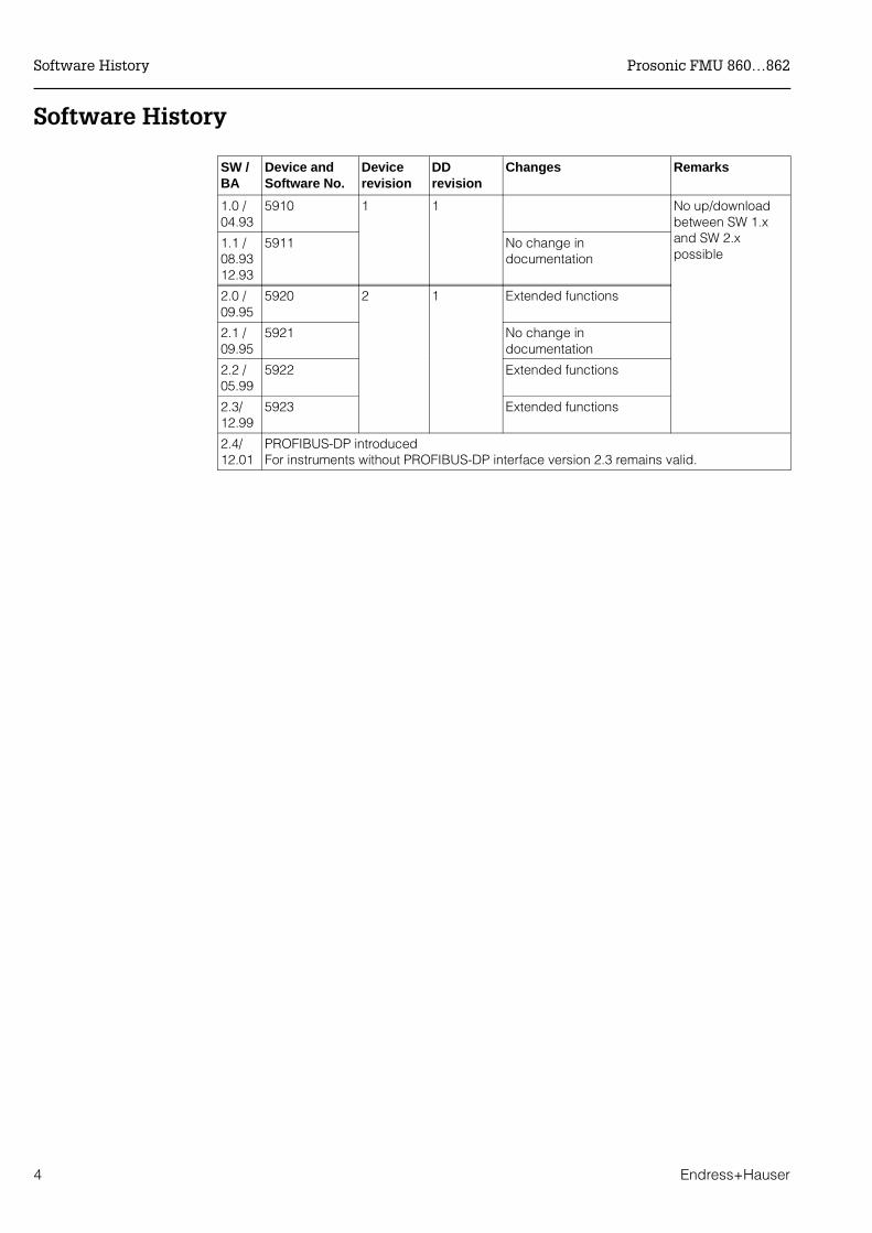
Software History
SW /BA
Device and Software No.
Devicerevision
DDrevision
Changes Remarks
1.0 /04.93
5910 1 1 No up/downloadbetween SW 1.xand SW 2.xpossible
1.1 /08.9312.93
5911 No change indocumentation
2.0 /09.95
5920 2 1 Extended functions
2.1 /09.95
5921 No change indocumentation
2.2 /05.99
5922 Extended functions
2.3/12.99
5923 Extended functions
2.4/12.01
PROFIBUS-DP introducedFor instruments without PROFIBUS-DP interface version 2.3 remains valid.
Software History Prosonic FMU 860…862
4 Endress+Hauser
Notes on Safety
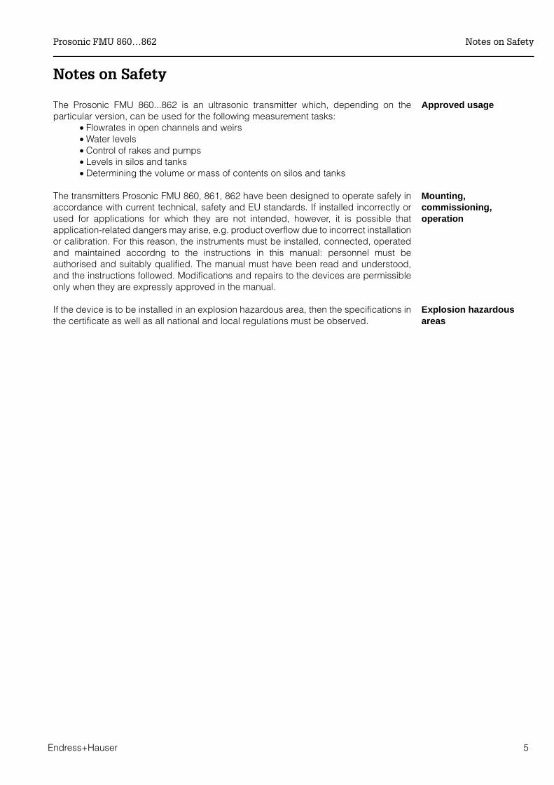
Approved usageThe Prosonic FMU 860...862 is an ultrasonic transmitter which, depending on theparticular version, can be used for the following measurement tasks:
• Flowrates in open channels and weirs• Water levels• Control of rakes and pumps• Levels in silos and tanks• Determining the volume or mass of contents on silos and tanks
Mounting,commissioning,operation
The transmitters Prosonic FMU 860, 861, 862 have been designed to operate safely inaccordance with current technical, safety and EU standards. If installed incorrectly orused for applications for which they are not intended, however, it is possible thatapplication-related dangers may arise, e.g. product overflow due to incorrect installationor calibration. For this reason, the instruments must be installed, connected, operatedand maintained accordng to the instructions in this manual: personnel must beauthorised and suitably qualified. The manual must have been read and understood,and the instructions followed. Modifications and repairs to the devices are permissibleonly when they are expressly approved in the manual.
Explosion hazardousareas
If the device is to be installed in an explosion hazardous area, then the specifications inthe certificate as well as all national and local regulations must be observed.
Prosonic FMU 860…862 Notes on Safety
Endress+Hauser 5
Safety Conventions and Symbols
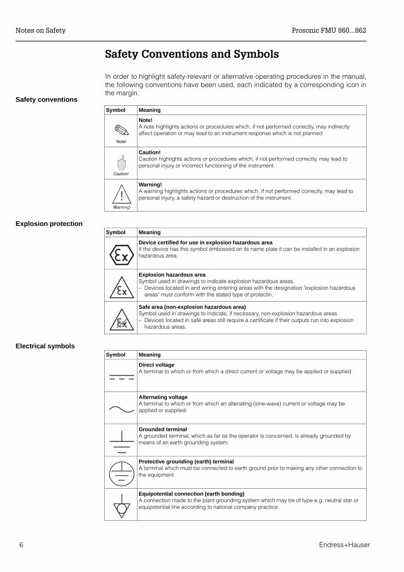
In order to highlight safety-relevant or alternative operating procedures in the manual,the following conventions have been used, each indicated by a corresponding icon inthe margin.
Symbol Meaning
Note!A note highlights actions or procedures which, if not performed correctly, may indirectlyaffect operation or may lead to an instrument response which is not planned.
Caution!Caution highlights actions or procedures which, if not performed correctly, may lead topersonal injury or incorrect functioning of the instrument.
Warning!A warning highlights actions or procedures which, if not performed correctly, may lead topersonal injury, a safety hazard or destruction of the instrument.
Explosion protectionSymbol Meaning
Device certified for use in explosion hazardous areaIf the device has this symbol embossed on its name plate it can be installed in an explosionhazardous area.
Explosion hazardous areaSymbol used in drawings to indicate explosion hazardous areas. – Devices located in and wiring entering areas with the designation "explosion hazardous
areas" must conform with the stated type of protectin.
Safe area (non-explosion hazardous area)Symbol used in drawings to indicate, if necessary, non-explosion hazardous areas.– Devices located in safe areas still require a certificate if their outputs run into explosion
hazardous areas.
Electrical symbolsSymbol Meaning
Direct voltageA terminal to which or from which a direct current or voltage may be applied or supplied.
Alternating voltageA terminal to which or from which an altenating (sine-wave) current or voltage may beapplied or supplied.
Grounded terminalA grounded terminal, which as far as the operator is concerned, is already grounded bymeans of an earth grounding system.
Protective grounding (earth) terminalA terminal which must be connected to earth ground prior to making any other connection tothe equipment.
Equipotential connection (earth bonding)A connection made to the plant grounding system which may be of type e.g. neutral star orequipotential line according to national company practice.
Note!
Caution!
Safety conventions
Notes on Safety Prosonic FMU 860...862
6 Endress+Hauser
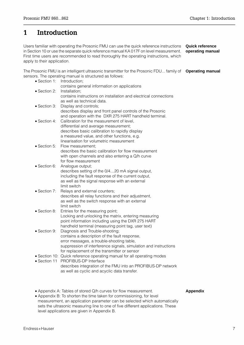
1 Introduction
Quick referenceoperating manual
Users familiar with operating the Prosonic FMU can use the quick reference instructionsin Section 10 or use the separate quick reference manual KA 017F on level measurement.First time users are recommended to read thoroughly the operating instructions, whichapply to their application.
Operating manualThe Prosonic FMU is an intelligent ultrasonic transmitter for the Prosonic FDU... family ofsensors. The operating manual is structured as follows:
• Section 1: Introduction;contains general information on applications
• Section 2: Installation;contains instructions on installation and electrical connectionsas well as technical data.
• Section 3: Display and controls;describes display and front panel controls of the Prosonic and operation with the DXR 275 HART handheld terminal.
• Section 4: Calibration for the measurement of level, differential and average measurement;describes basic calibration to rapidly display a measured value, and other functions, e.g. linearisation for volumetric measurement
• Section 5: Flow measurement;describes the basic calibration for flow measurement with open channels and also entering a Q/h curvefor flow measurement
• Section 6: Analogue output;describes setting of the 0/4…20 mA signal output,including the fault response of the current output, as well as the signal response with an external limit switch
• Section 7: Relays and external counters;describes all relay functions and their adjustment, as well as the switch response with an external limit switch
• Section 8: Entries for the measuring point;Locking and unlocking the matrix, entering measuring point information including using the DXR 275 HARThandheld terminal (measuring point tag, user text)
• Section 9: Diagnosis and Trouble-shooting;contains a description of the fault response,error messages, a trouble-shooting table, suppression of interference signals, simulation and instructions for replacement of the transmitter or sensor
• Section 10: Quick reference operating manual for all operating modes• Section 11 PROFIBUS-DP Interface
describes integration of the FMU into an PROFIBUS-DP networkas well as cyclic and acyclic data transfer.
Appendix • Appendix A: Tables of stored Q/h curves for flow measurement.• Appendix B: To shorten the time taken for commissioning, for level
measurement, an application parameter can be selected which automaticallysets the ultrasonic measuring line to one of five different applications. Theselevel applications are given in Appendix B.
Prosonic FMU 860...862 Chapter 1: Introduction
Endress+Hauser 7
Further documentation In addition to this manual, the following publications also provide information on theProsonic FMU:
• TI 189F for installing the Prosonic FDU 8... ultrasonic sensor• BA 139F for configuring the Prosonic using the HART Communicator DXR 275
handheld terminal• BA 134F for connecting to the Rackbus RS 485• KA 017F for quickly calibrating the most important functions for level
measurement• BA 198F PROFIBUS-DP/-PA: Guidelines for planning and commissioning
1.1 Features
The Prosonic transmitter is available in various versions...• for the field or control room• single or two-channel versions with three or five relays, also with totaliser• with optional serial interface for remote operation (HART protocol). • RS-485- or PROFIBUS-DP interface• The analogue output signal is a standard 4…20 mA, current, selectable to 0…20 mA.Simple operation and easy commissioning with• all calibrated values arranged clearly in a matrix• different functions for linearisation, totalising, all common Q/h curves can be called
up.• Signal pattern recognition using fuzzy logic elements and selectable application
parameters to shorten commissioning times and to ensure long-term and correctultrasonic measurement.
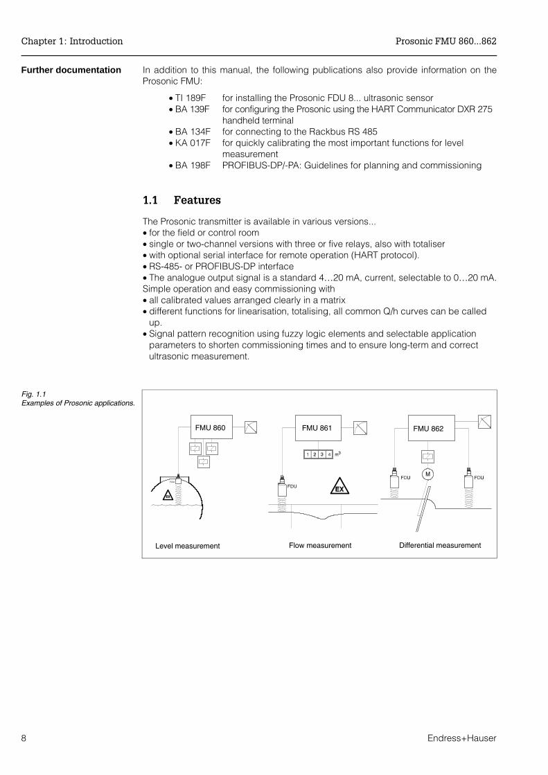
FMU 860 FMU 861 FMU 862
Fig. 1.1Examples of Prosonic applications.
Level measurement Flow measurement Differential measurement
Chapter 1: Introduction Prosonic FMU 860...862
8 Endress+Hauser
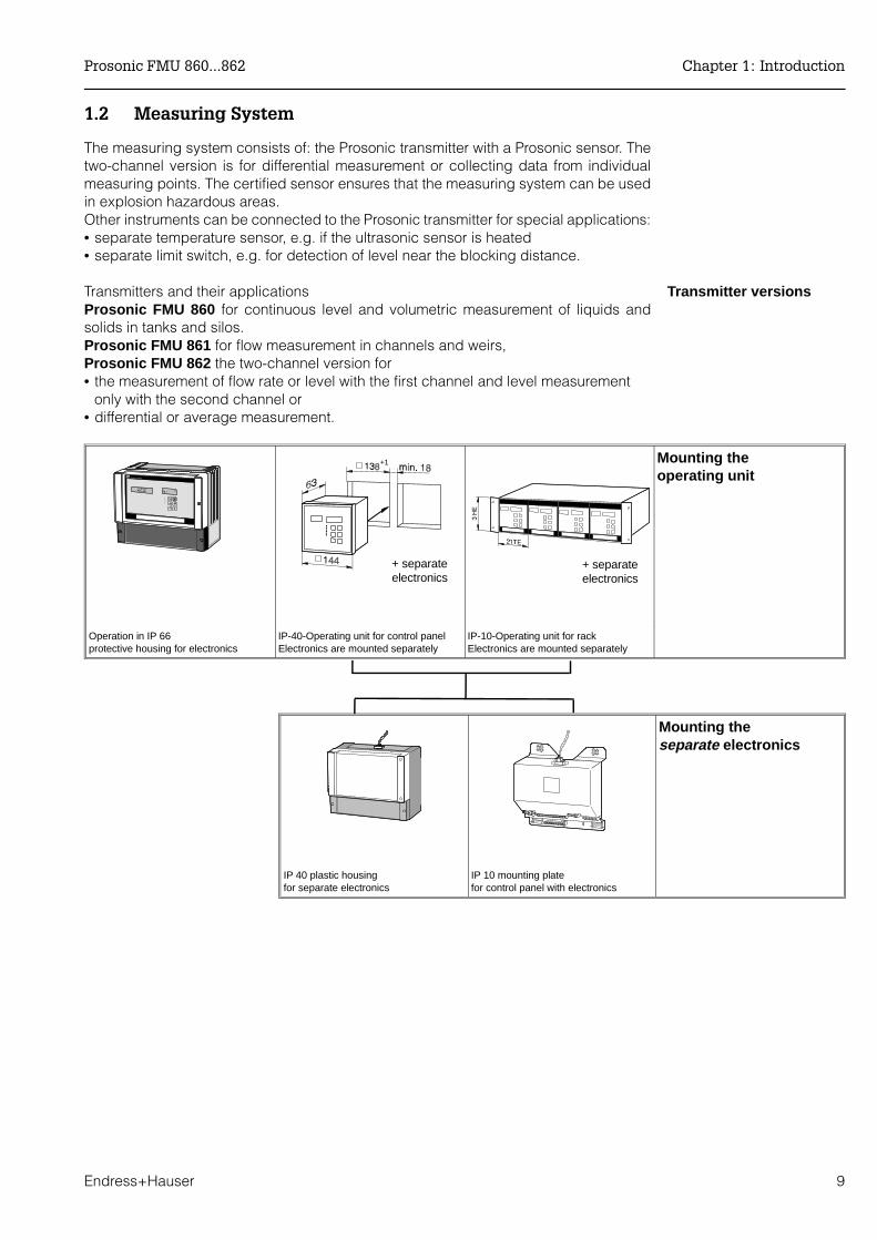
1.2 Measuring System
The measuring system consists of: the Prosonic transmitter with a Prosonic sensor. Thetwo-channel version is for differential measurement or collecting data from individualmeasuring points. The certified sensor ensures that the measuring system can be usedin explosion hazardous areas.Other instruments can be connected to the Prosonic transmitter for special applications:• separate temperature sensor, e.g. if the ultrasonic sensor is heated• separate limit switch, e.g. for detection of level near the blocking distance.
Transmitter versionsTransmitters and their applicationsProsonic FMU 860 for continuous level and volumetric measurement of liquids andsolids in tanks and silos.Prosonic FMU 861 for flow measurement in channels and weirs, Prosonic FMU 862 the two-channel version for• the measurement of flow rate or level with the first channel and level measurement
only with the second channel or • differential or average measurement.
Mounting theoperating unit
Operation in IP 66protective housing for electronics
IP-40-Operating unit for control panelElectronics are mounted separately
IP-10-Operating unit for rackElectronics are mounted separately
+ separate electronics
+ separate electronics
IP 40 plastic housingfor separate electronics
IP 10 mounting platefor control panel with electronics
Mounting theseparate electronics
+1
Prosonic FMU 860...862 Chapter 1: Introduction
Endress+Hauser 9
Accessories • All-weather cover for the protective housing; material: aluminium, blue lacquered(Order No. 919 567-0000); stainless steel 1.4301 (Order No. 919 567-0001);Weight: approx. 1 kg. Mounting screws supplied.
• Post mounting material: galvanised steel (for 2" post Order No. 919 566-0000; for 1" post: 919 566-1000); stainless steel 1.4301; (for 2" post Order No. 919 566-0001; for 1" post: 919 566-1001);Weight: approx. 1 kg. Mounting screws and nuts supplied.
• HART Communicator DXR 275. Handheld terminal with integrated serial interface forHART protocol (see operating manual BA 139F/00/en).
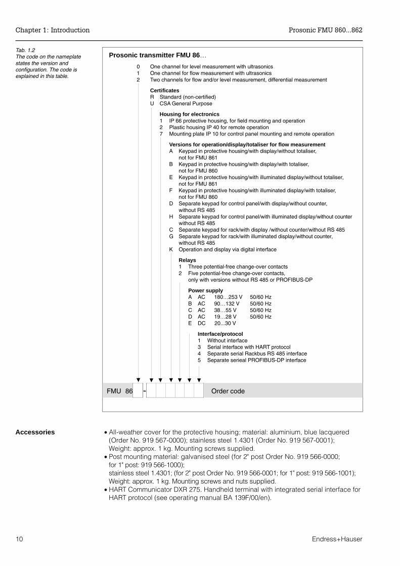
Prosonic transmitter FMU 86…
0 One channel for level measurement with ultrasonics1 One channel for flow measurement with ultrasonics2 Two channels for flow and/or level measurement, differential measurement
CertificatesR Standard (non-certified)U CSA General Purpose
Housing for electronics1 IP 66 protective housing, for field mounting and operation2 Plastic housing IP 40 for remote operation7 Mounting plate IP 10 for control panel mounting and remote operation
Versions for operation/display/totaliser for flow measurementA Keypad in protective housing/with display/without totaliser,
not for FMU 861B Keypad in protective housing/with display/with totaliser,
not for FMU 860E Keypad in protective housing/with illuminated display/without totaliser,
not for FMU 861F Keypad in protective housing/with illuminated display/with totaliser,
not for FMU 860D Separate keypad for control panel/with display/without counter,
without RS 485H Separate keypad for control panel/with illuminated display/without counter
without RS 485C Separate keypad for rack/with display /without counter/without RS 485G Separate keypad for rack/with illuminated display/without counter,
without RS 485K Operation and display via digital interface
Relays1 Three potential-free change-over contacts2 Five potential-free change-over contacts,
only with versions without RS 485 or PROFIBUS-DP
Power supplyA AC 180…253 V 50/60 HzB AC 90…132 V 50/60 HzC AC 38…55 V 50/60 HzD AC 19…28 V 50/60 HzE DC 20...30 V
Interface/protocol1 Without interface3 Serial interface with HART protocol4 Separate serial Rackbus RS 485 interface5 Separate serieal PROFIBUS-DP interface
Tab. 1.2The code on the nameplatestates the version andconfiguration. The code isexplained in this table.
FMU 86 Order code
Chapter 1: Introduction Prosonic FMU 860...862
10 Endress+Hauser
• The overvoltage protection and power supply units for sensor heating for up to 2sensors in IP 66 protective housing. Power supply unit (24 V DC) for sensor heatingwith integrated overvoltage protection for power supply. Power supply 230 V (+15%/-20%). Dimensions: IP 66 protective housingOrder No.: 215095-0000
• Overvoltage protection unit in IP 66 protective housing.Dimensions: IP 66 protective housing. Order No.: 215095-0001
• Power supply unit (24 V DC) for sensor heating of up to 2 sensors in IP 66 protectivehousing. Power supply 230 V (+15%/-20%). Dimensions: IP 66 protective housing. Order No.: 215095-0002
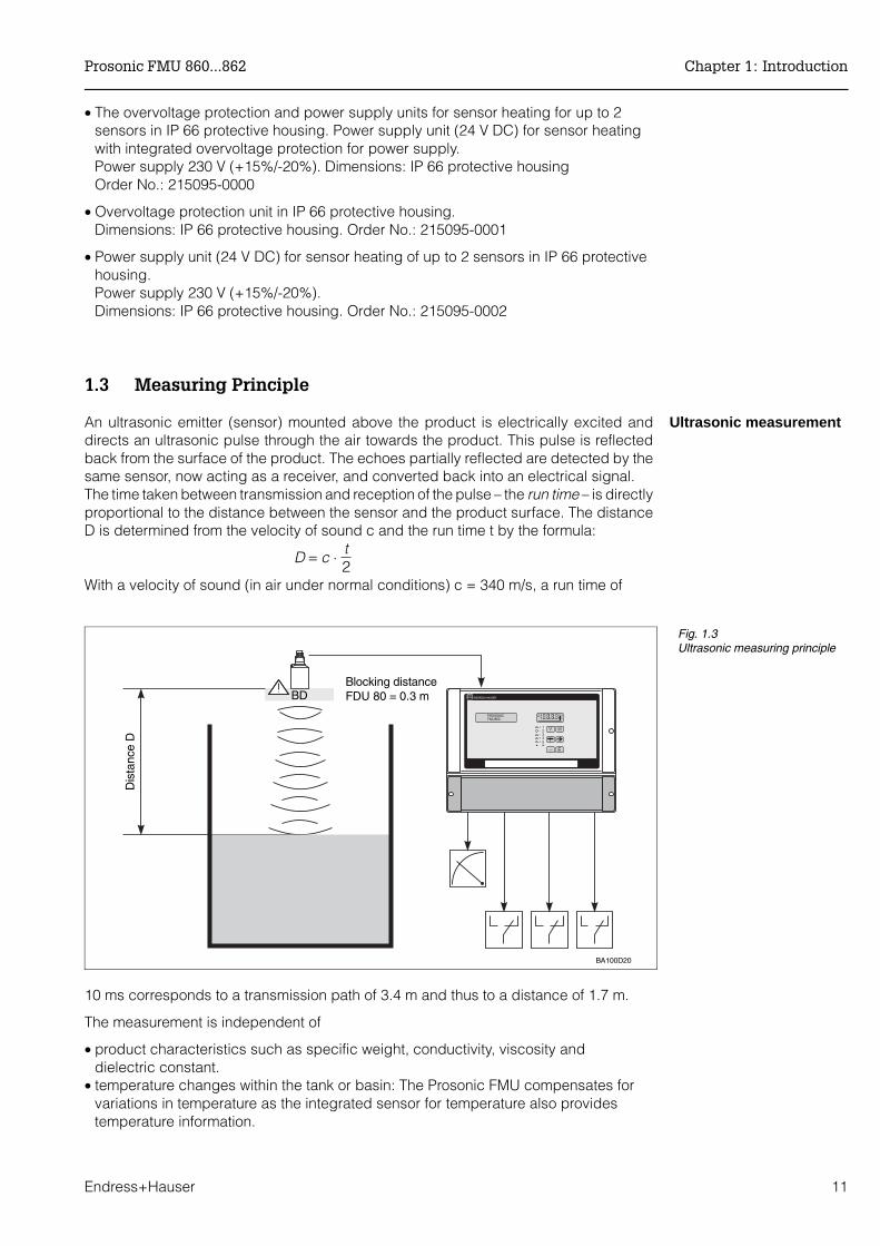
1.3 Measuring Principle
Ultrasonic measurementAn ultrasonic emitter (sensor) mounted above the product is electrically excited anddirects an ultrasonic pulse through the air towards the product. This pulse is reflectedback from the surface of the product. The echoes partially reflected are detected by thesame sensor, now acting as a receiver, and converted back into an electrical signal.The time taken between transmission and reception of the pulse – the run time – is directlyproportional to the distance between the sensor and the product surface. The distanceD is determined from the velocity of sound c and the run time t by the formula:
D = c ⋅ t2
With a velocity of sound (in air under normal conditions) c = 340 m/s, a run time of
10 ms corresponds to a transmission path of 3.4 m and thus to a distance of 1.7 m.
The measurement is independent of
• product characteristics such as specific weight, conductivity, viscosity anddielectric constant.
• temperature changes within the tank or basin: The Prosonic FMU compensates forvariations in temperature as the integrated sensor for temperature also providestemperature information.
ENDRESS+HAUSER
FMU 860PROSONIC
12
43
5
BA100D20
Blocking distanceFDU 80 = 0.3 mBD
Dis
tanc
e D
Fig. 1.3Ultrasonic measuring principle
Prosonic FMU 860...862 Chapter 1: Introduction
Endress+Hauser 11

Measuring range andblocking distance
The maximum measuring range of the measuring system dependent on the sensor usedand is up to 5 m in liquids and up to 70 m in bulk solids (see also Technical Datapages 26…27). Due to the ringing time characteristics of the sensor, there is a zoneimmediately below it from which returning echoes cannot be detected. This is known asthe blocking distance BD and determines the minimum distance between the sensordiaphragm and the maximum level in the silo. This is a function of the type of sensorused.The end of the measuring range is determined by the attenuation of the ultrasonic pulseby the air as well as by the strength of the reflection from the product surface.
Note!Please note when mounting: Levels coming within the blocking distance can cause theinstrument to malfunction.Note!
Chapter 1: Introduction Prosonic FMU 860...862
12 Endress+Hauser
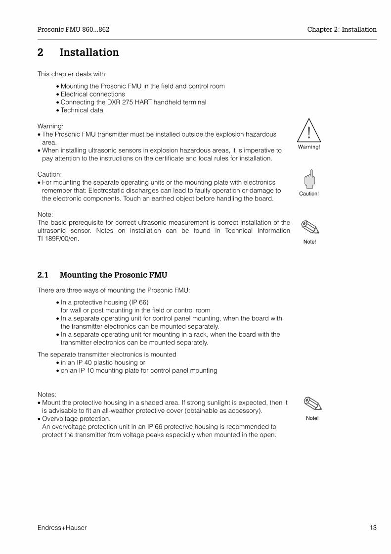
2 Installation
This chapter deals with:
• Mounting the Prosonic FMU in the field and control room• Electrical connections• Connecting the DXR 275 HART handheld terminal• Technical data
Warning:• The Prosonic FMU transmitter must be installed outside the explosion hazardous
area.• When installing ultrasonic sensors in explosion hazardous areas, it is imperative to
pay attention to the instructions on the certificate and local rules for installation.
Caution:• For mounting the separate operating units or the mounting plate with electronics
remember that: Electrostatic discharges can lead to faulty operation or damage tothe electronic components. Touch an earthed object before handling the board.
Note:The basic prerequisite for correct ultrasonic measurement is correct installation of theultrasonic sensor. Notes on installation can be found in Technical InformationTI 189F/00/en.
2.1 Mounting the Prosonic FMU
There are three ways of mounting the Prosonic FMU:
• In a protective housing (IP 66)for wall or post mounting in the field or control room
• In a separate operating unit for control panel mounting, when the board withthe transmitter electronics can be mounted separately.
• In a separate operating unit for mounting in a rack, when the board with thetransmitter electronics can be mounted separately.
The separate transmitter electronics is mounted• in an IP 40 plastic housing or• on an IP 10 mounting plate for control panel mounting
Notes:• Mount the protective housing in a shaded area. If strong sunlight is expected, then it
is advisable to fit an all-weather protective cover (obtainable as accessory). • Overvoltage protection.
An overvoltage protection unit in an IP 66 protective housing is recommended toprotect the transmitter from voltage peaks especially when mounted in the open.
Note!
Note!
Caution!
Prosonic FMU 860...862 Chapter 2: Installation
Endress+Hauser 13

Mounting the IP 66protective housing andthe IP 40 plastic housing
The following illustrations provide all instructions needed for mounting. Mounting theall-weather protective cover on the IP 66 protective housing is also illustrated. Mountingmaterial (screws or nuts) for post mounting and the all weather protective cover isenclosed. Note: The separate transmitter electronics is connected by a standard multicore cable(in scope of delivery).
Fig. 2.1Mounting dimensions andclearances of the IP 66protective housing and the IP 40 plastic housing withseparate operating unit (leave10 cm area above the IP 40plastic housing for the plug)
Separateconnectionchamber
Fig. 2.2Cable entry through the bottomor rear.Mounting screws: max. ø 4.5 mm, screw head max. ø 9.5
Chapter 2: Installation Prosonic FMU 860...862
14 Endress+Hauser

Mounting the IP 10mounting plate
Fig. 2.3Mounting all-weather protectivecover and attaching thetransmitter to a post
12,7 10
1011
280
10,5
24,5
9
6,4
92
Fig. 2.4Dimensions of the IP 10mounting plate for control panelmounting (leave 10 cm areaabove the IP 40 plastic housingfor the plug)
Prosonic FMU 860...862 Chapter 2: Installation
Endress+Hauser 15
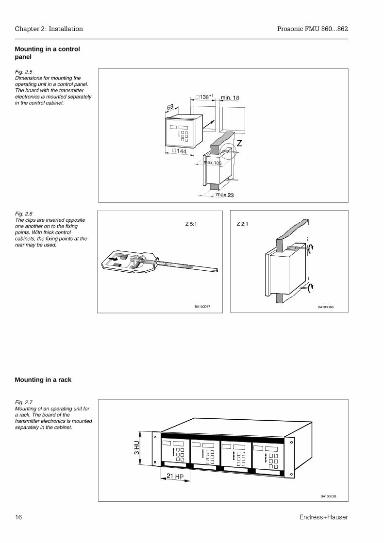
Mounting in a controlpanel
Mounting in a rack
Fig. 2.5Dimensions for mounting the operating unit in a control panel.The board with the transmitterelectronics is mounted separatelyin the control cabinet.
Z
BA100D66
Z 2:1
BA100D67
Z 5:1
Fig. 2.6The clips are inserted oppositeone another on to the fixingpoints. With thick controlcabinets, the fixing points at therear may be used.
BA100E28
Fig. 2.7Mounting of an operating unit fora rack. The board of thetransmitter electronics is mountedseparately in the cabinet.
Chapter 2: Installation Prosonic FMU 860...862
16 Endress+Hauser
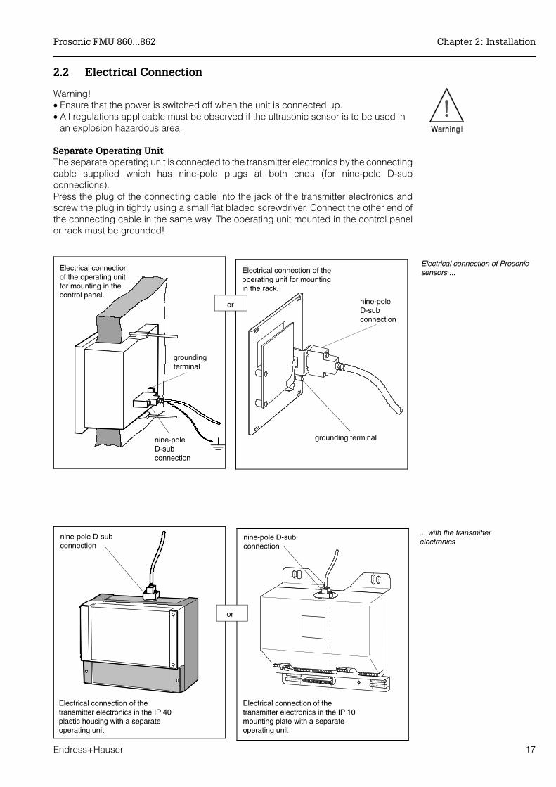
2.2 Electrical Connection
Warning!• Ensure that the power is switched off when the unit is connected up.• All regulations applicable must be observed if the ultrasonic sensor is to be used in
an explosion hazardous area.
Separate Operating UnitThe separate operating unit is connected to the transmitter electronics by the connectingcable supplied which has nine-pole plugs at both ends (for nine-pole D-subconnections).Press the plug of the connecting cable into the jack of the transmitter electronics andscrew the plug in tightly using a small flat bladed screwdriver. Connect the other end ofthe connecting cable in the same way. The operating unit mounted in the control panelor rack must be grounded!
Electrical connection of theoperating unit for mountingin the rack.
nine-poleD-subconnection
grounding terminal
Electrical connection of Prosonicsensors ...
nine-pole D-subconnection
Electrical connection of thetransmitter electronics in the IP 40plastic housing with a separateoperating unit
Electrical connectionof the operating unitfor mounting in thecontrol panel.
grounding terminal
nine-poleD-subconnection
or
nine-pole D-subconnection
Electrical connection of thetransmitter electronics in the IP 10mounting plate with a separateoperating unit
or
... with the transmitterelectronics
Prosonic FMU 860...862 Chapter 2: Installation
Endress+Hauser 17

Terminal block The terminal block, for cable diameters up to 2.5 mm2, is located in a separate connectionchamber which is accessible by opening the plastic cover. The pre-pressed knock-outsin the connection area have to be removed for cable entry (underside for 5 x Pg 16,4 x Pg 13.5, rear 5 x Pg 16). All terminals are clearly marked. Fig. 2.8 shows the wiringdiagram of the Prosonic FMU (Terminal 3 is only for internal ground connection).
Electrical isolation The current output, relay outputs, RS 485 interface, mains connection and sensor inputare electrically isolated. On FMU 862, the two current outputs are electrically connected,likewise the two sensors inputs. (In Fig. 2.8, the electrically isolated areas are indicatedby the thick, speckled lines).
Power switch When using the public powers supply, install an easily accectable power switch in theproximity of the device. Mark the power switch as a disconnector for the device(IEC/EN 61010).
80 81 827063 7164 90 91 92
YE YERD RD
L+ L-L1 N
1 2 3 4 5 6 7 3111 21 41
21 3 4 5
51 603212 22 42 52 613313 23 43 53 62
2
RS-485
B A
11 31 41
3 4 5
5112 32 42 5213 33 43 53
RS
-485
GN
DR
xD/T
xD-N
RxD
/TxD
-P
24V
AC
; 48V
AC
;11
5V
AC
; 230
VA
C
L1 N PE
20 …
30V
DC
L+ L-
0/4
… 20
mA
0/4
… 20
mA
Liqu
ipha
ntS
olip
hant
Syn
c.F
MU
Tem
p.
Sen
sor
1
Sen
sor
2
DP
A B
11 31 41
3 4 5
5112 32 42 5213 33 43 53
DP
GN
DR
xD/T
xD-N
RxD
/TxD
-P
for FMU 862only
for FMU 862only
terminals fitted tothe version with5 relays only
RS-485 versionProfibus-DP version
Fig. 2.8Assignment of the terminal stripconnections.The electricallyisolated parts are separated bylines shown in half-tone.
Chapter 2: Installation Prosonic FMU 860...862
18 Endress+Hauser

Ground cableIn order to ensure protection from contact and reliable isolation according toDIN/VDE 0160, the ground cable must be connected to the metallic terminal blocksupplied.
Analog and relay outputs• Only a unit whose input is not potential-free may be connected direct to the currentoutput.
• The number of potential-free units is unlimited, paying due respect to the min. ormax. load, see technical data in this chapter.
• For max. permissible contact loading see technical data.
Separate limit switchinput
All Prosonic transmitters have an additional limit switch input. Exceeding the level tocome within the blocking distance of the sensor is also indicated promptly by the display,the signal output and the relays.
Caution!The maximum short-circuit current is 20 mA; for 24 V supply
Externaltemperature sensor
An external temperature sensor can be connected to the Prosonic transmitter. This isnecessary if the sensor is heated (with the FDU 80 or FDU 81 only as required) or if thetemperature is not to be measured inside the sensor.
in Housing
Ground terminal
Housing less
Ground terminal
Maximumshort-circuit current20 mA
e.g. Liquiphant breaker or maker(passive)
FDU
Max.
FMU 86…
Fig. 2.9Left:All transmitters have a separatelimit switch input
Right: Separate switching input e.g. forLiquiphant or Soliphant or for anexternal passive maker or breaker
Caution!
Prosonic FMU 860...862 Chapter 2: Installation
Endress+Hauser 19
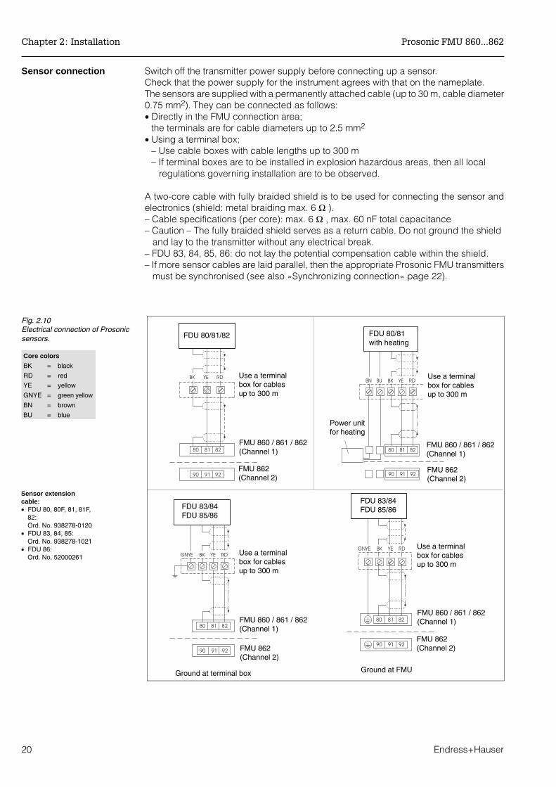
Sensor connection Switch off the transmitter power supply before connecting up a sensor. Check that the power supply for the instrument agrees with that on the nameplate.The sensors are supplied with a permanently attached cable (up to 30 m, cable diameter0.75 mm2). They can be connected as follows:• Directly in the FMU connection area;
the terminals are for cable diameters up to 2.5 mm2
• Using a terminal box;– Use cable boxes with cable lengths up to 300 m– If terminal boxes are to be installed in explosion hazardous areas, then all local regulations governing installation are to be observed.
A two-core cable with fully braided shield is to be used for connecting the sensor andelectronics (shield: metal braiding max. 6 Ω ).– Cable specifications (per core): max. 6 Ω , max. 60 nF total capacitance– Caution – The fully braided shield serves as a return cable. Do not ground the shield and lay to the transmitter without any electrical break.– FDU 83, 84, 85, 86: do not lay the potential compensation cable within the shield.– If more sensor cables are laid parallel, then the appropriate Prosonic FMU transmitters must be synchronised (see also »Synchronizing connection« page 22).
Ground at FMUGround at terminal box
Use a terminalbox for cablesup to 300 m
FMU 860 / 861 / 862(Channel 1)
FMU 862(Channel 2)
Fig. 2.10Electrical connection of Prosonicsensors. FDU 80/81/82
Use a terminalbox for cablesup to 300 m
FMU 860 / 861 / 862(Channel 1)
FMU 862(Channel 2)
FDU 83/84FDU 85/86
Use a terminalbox for cablesup to 300 m
FMU 860 / 861 / 862(Channel 1)
FMU 862(Channel 2)
FDU 83/84FDU 85/86
FDU 80/81with heating
Use a terminalbox for cablesup to 300 m
FMU 860 / 861 / 862(Channel 1)
FMU 862(Channel 2)
Power unitfor heating
Core colors
BK = black
RD = red
YE = yellow
GNYE = green yellow
BN = brown
BU = blue
Sensor extension cable:• FDU 80, 80F, 81, 81F,
82:Ord. No. 938278-0120
• FDU 83, 84, 85:Ord. No. 938278-1021
• FDU 86:Ord. No. 52000261
Chapter 2: Installation Prosonic FMU 860...862
20 Endress+Hauser
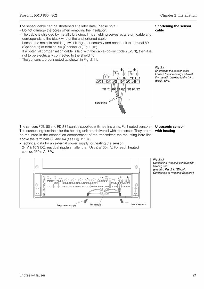
Shortening the sensorcable
The sensor cable can be shortened at a later date. Please note: – Do not damage the cores when removing the insulation.– The cable is shielded by metallic braiding. This shielding serves as a return cable and corresponds to the black wire of the unshortened cable. Loosen the metallic braiding, twist it together securely and connect it to terminal 80 (Channel 1) or terminal 90 (Channel 2) (Fig. 2.12). If a potential compensation cable is laid with the cable (colour code YE-GN), then it is not to be electrically connected to the shielding.– The sensors are connected as shown in Fig. 2.11.
Ultrasonic sensor with heating
The sensors FDU 80 and FDU 81 can be supplied with heating units. For heated sensors:The connecting terminals for the heating unit are delivered with the sensor. They are tobe mounted in the connection compartment of the transmitter; the mounting bore liesabove the terminals 63 and 64 (see Fig. 2.13).• Technical data for an external power supply for heating the sensor
24 V ± 10% DC, residual ripple smaller than Uss ≤ ±100 mV. For each heatedsensor, 250 mA, 8 W.
screening
Fig. 2.11Shortening the sensor cableLoosen the screening and twistthe metallic braiding to the third(black) wire.
to power supply terminals from sensor
Fig. 2.12Connecting Prosonic sensors withheating unit(see also Fig. 2.11 ”ElectricConnection of Prosonic Sensors”)
Prosonic FMU 860...862 Chapter 2: Installation
Endress+Hauser 21
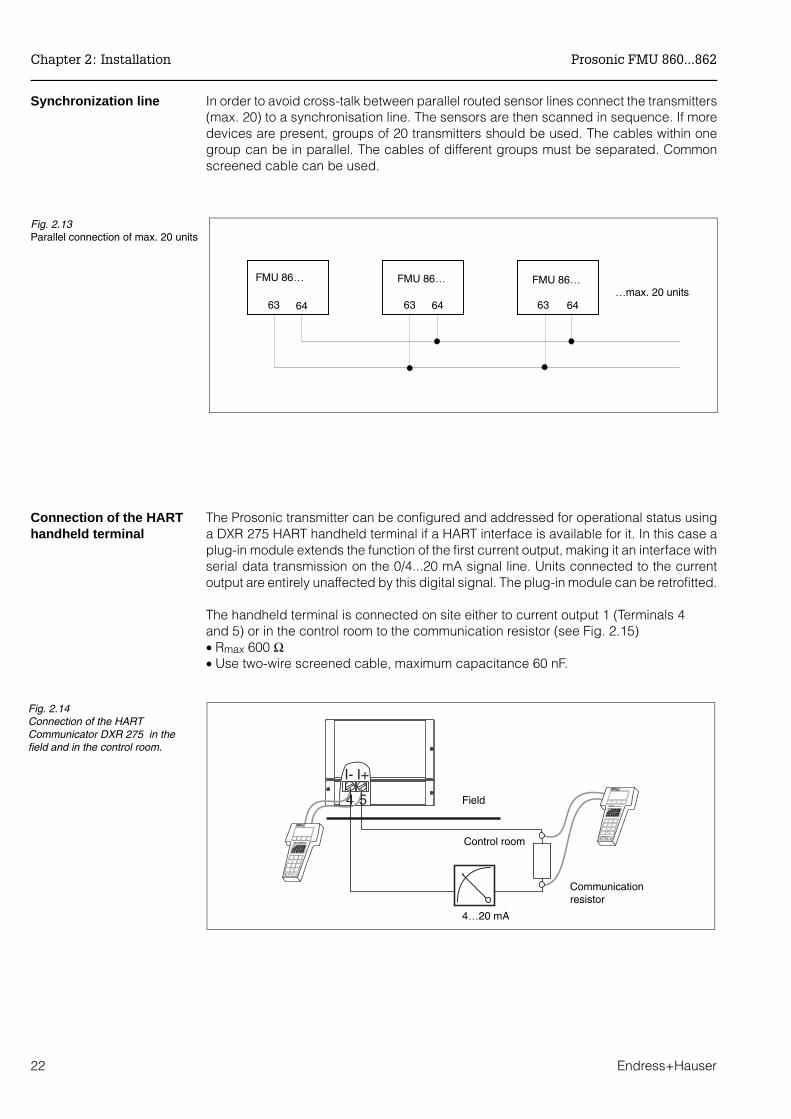
Synchronization line In order to avoid cross-talk between parallel routed sensor lines connect the transmitters(max. 20) to a synchronisation line. The sensors are then scanned in sequence. If moredevices are present, groups of 20 transmitters should be used. The cables within onegroup can be in parallel. The cables of different groups must be separated. Commonscreened cable can be used.
Connection of the HARThandheld terminal
The Prosonic transmitter can be configured and addressed for operational status usinga DXR 275 HART handheld terminal if a HART interface is available for it. In this case aplug-in module extends the function of the first current output, making it an interface withserial data transmission on the 0/4...20 mA signal line. Units connected to the currentoutput are entirely unaffected by this digital signal. The plug-in module can be retrofitted.
The handheld terminal is connected on site either to current output 1 (Terminals 4 and 5) or in the control room to the communication resistor (see Fig. 2.15)• Rmax 600 Ω• Use two-wire screened cable, maximum capacitance 60 nF.
FMU 86… FMU 86… FMU 86…
63 64 63 64 63 64…max. 20 units
Fig. 2.13Parallel connection of max. 20 units
-I-
4 5
I+
Communicationresistor
Field
Control room
4…20 mA
Fig. 2.14Connection of the HARTCommunicator DXR 275 in thefield and in the control room.
Chapter 2: Installation Prosonic FMU 860...862
22 Endress+Hauser

2.3 Technical Data
Manufacturer Endress+Hauser GmbH+Co. General specifications
Function Transmitter for level or flow measurement with one or twoProsonic sensors
Interfaces 0/4…20 mA, optional RS 485 or PROFIBUS-DP
Miscellaneous CE-mark
Signal input, channels 1 and 2 Input characteristics
Sensor: one Prosonic FDU 8... (nominal measuring range 5...70 m). FMU 862: two Prosonic FDU 8... (may be different).
Separate switching input external passive limit switch (maker or breaker) or PNP switch,e.g. Liquiphant or Soliphant (24 V, max. short-circuit 20 mA)
Separate temperaturesensor input for FMT 131(Temperature sensorFMT 131 is available asaccessory)
– Applications:With heated sensors or if the temperature does not have to be measured in the sensor.
– Function:For temperature compensation of the sound run time in flumes.
– NTC design
Analog outputs Output characteristics
Output – 4...20 mA, switchable to 0...20 mA(current signal with inverse function)
– for FMU 862: same values for second channel, switchable together with channel 1 to 0…20 mA
– with plug-in module for serial interface (HART)– 4 mA threshold switchable
Signal underflow / Signal overflow
Signal underflow Signal overflow4…20 mA 3.8…4 mA 20…20.5 mA0…20 mA –0.5…0 mA 20…20.5 mA
Output on alarm 0 ... 20mA 4 ... 20 mA– 10 % –2 mA 2.4 mA110 % 22 mA 21.6 mAhold last measured value last measured value
Current limitation 24 mA
Measuring uncertainty 0.2 % for maximum measuring span and smoth surface
Damping 0…300 sec.
Max. load 600 ΩCommunication resistor: 250 Ω
Load effekt negligible
Relays
Typ – Three (relay 1, 2, 5) or five independent relays each with apotential-free changeover contact
– Prosonic with RS 485 or PROFIBUS-DP, as three relay version (relay 3, 4, 5) only
Function – Limit switch– Fault message– Tendency message– Pulse generator (FMU 861 and 862 only)
(max. counting rate 2 Hz, pulse with 200 msec)– Time pulse generator (FMU 861 and 862 only)– Back water alarm (FMU 862 only)
Limit values 4 A, 250 VAC, 1000 VA for cos ϕ = 0.7; 35 VDC and 100 W
Prosonic FMU 860...862 Chapter 2: Installation
Endress+Hauser 23
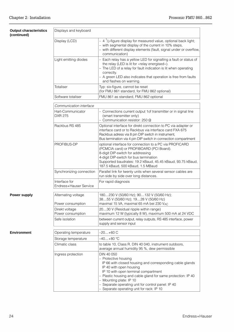
Output characteristics(continued)
Displays and keyboard
Display (LCD) – 4 1/2-figure display for measured value, optional back light;– with segmental display of the current in 10% steps,– with different display elements (fault, signal under or overflow,
communication)
Light emitting diodes – Each relay has a yellow LED for signalling a fault or status ofthe relay (LED is lit for »relay energised«).
– The LED of a relay for fault indication is lit when operatingcorrectly.
– A green LED also indicates that operation is free from faultsand flashes on warning.
Totaliser Typ: six-figure, cannot be reset(for FMU 861 standard, for FMU 862 optional)
Software totaliser FMU 861 as standard, FMU 862 optional
Communication interface
Hart-CommunicatorDXR 275
– Connections current output 1of transmitter or in signal line(smart transmitter only)
– Communication resistor: 250 ΩRackbus RS 485 Optional interface for direkt connection to PC via adapter or
interface card or to Rackbus via interface card FXA 675Rackbus adress via 8 pin DIP switch in instrument,Bus termination via 4 pin DIP switch in connection compartment
PROFIBUS-DP optional interface for connection to a PC via PROFICARD(PCMCIA card) or PROFIBOARD (PCI Board).8-digit DIP-switch for addressing4-digit DIP-switch for bus terminationSupported baudrates: 19.2 kBaud, 45.45 kBaud, 93.75 kBaud,187.5 kBaud, 500 kBaud, 1.5 MBaud
Synchronizing connection Parallel link for twenty units when several sensor cables arerun side by side over long distances.
Interface forEndress+Hauser Service
For rapid diagnosis
Power supply Alternating voltage
Power consumption
180…230 V (50/60 Hz); 90…132 V (50/60 Hz); 38…55 V (50/60 Hz); 19…28 V (50/60 Hz)maximal 15 VA, maximal 65 mA bei 230 VAC
Direkt voltagePower consumption
20…30 V (Residual ripple within range)maximum 12 W (typically 8 W), maximum 500 mA at 24 VDC
Safe isolation between current output, relay outputs, RS 485 interface, powersupply and sensor input
Environment Operating temperature –20…+60 C
Storage temperature –40…+80 °C
Climatic class to table 10, Class R, DIN 40 040, instrument outdoors, average annual humidity 95 %, dew permissible
Ingress protection DIN 40 050– Protective housing IP 66 with closed housing and corresponding cable glands IP 40 with open housing IP 10 with open terminal compartment– Plastic housing and cable gland for same protection: IP 40– Mounting plate: IP 10– Separate operating unit for control panel: IP 40– Separate operating unit for rack: IP 10
Chapter 2: Installation Prosonic FMU 860...862
24 Endress+Hauser
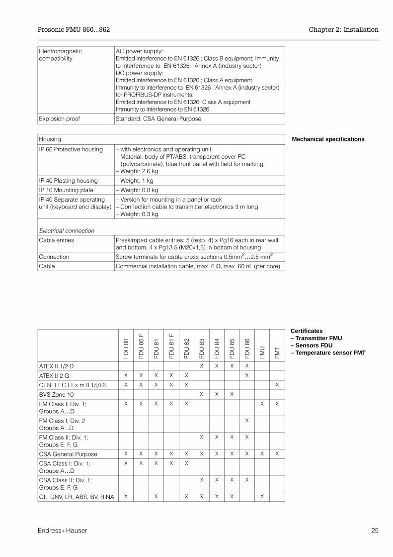
Electromagneticcompatibility
AC power supply:Emitted interference to EN 61326 ; Class B equipment; Immunityto interference to EN 61326 ; Annex A (industry sector)DC power supply:Emitted interference to EN 61326 ; Class A equipmentImmunity to interference to EN 61326 ; Annex A (industry sector)for PROFIBUS-DP instruments:Emitted interference to EN 61326; Class A equipmentImmunity to interference to EN 61326
Explosion proof Standard; CSA General Purpose
Housing Mechanical specifications
IP 66 Protective housing – with electronics and operating unit– Material: body of PT/ABS, transparent cover PC (polycarbonate), blue front panel with field for marking– Weight: 2.6 kg
IP 40 Plasting housing – Weight: 1 kg
IP 10 Mounting plate – Weight: 0.8 kg
IP 40 Separate operatingunit (keyboard and display)
– Version for mounting in a panel or rack– Connection cable to transmitter electronics 3 m long– Weight: 0.3 kg
Electrical connection
Cable entries Preskimped cable entries: 5 (resp. 4) x Pg16 each in rear walland bottom, 4 x Pg13.5 (M20x1,5) in bottom of housing
Connection Screw terminals for cable cross sections 0.5mm2…2.5 mm2
Cable Commercial installation cable, max. 6 Ω, max. 60 nF (per core)
Certificates– Transmitter FMU– Sensors FDU– Temperature sensor FMT
FDU
80
FDU
80
F
FDU
81
FDU
81
F
FDU
82
FDU
83
FDU
84
FDU
85
FDU
86
FMU
FMT
ATEX II 1/2 D X X X X
ATEX II 2 G X X X X X X
CENELEC EEx m II T5/T6 X X X X X X
BVS Zone 10 X X X
FM Class I; Div. 1; Groups A…D
X X X X X X X
FM Class I; Div. 2Groups A...D
X
FM Class II; Div. 1; Groups E, F, G
X X X X
CSA General Purpose X X X X X X X X X X X
CSA Class I; Div. 1;Groups A…D
X X X X X
CSA Class II; Div. 1; Groups E, F, G
X X X X
GL, DNV, LR, ABS, BV, RINA X X X X X X X
Prosonic FMU 860...862 Chapter 2: Installation
Endress+Hauser 25
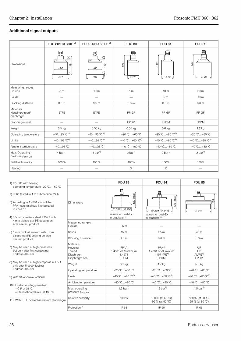
Additional signal outputs
FDU 83 FDU 84 FDU 85
Dimensions
Measuring rangesLiquids 25 m
Solids 15 m 25 m 45 m
Blocking distance 1.0 m 0.8 m 0.8 m
Materials HousingThreadDiaphragmDiaphragm seal
PPA3)
1.4301 or Aluminium1.4571EPDM
PPA3)
1.4301 or Aluminium1.4571/PE4)
EPDM
UPUP
AL/PE5)
EPDM
Weight 3.1 kg 4.7 kg 5.0 kg
Operating temperature –20 °C…+80 °C –20 °C…+80 °C –20 °C…+80 °C
Limits –40 °C…+80 °C8) –40 °C…+80 °C8) –40 °C…+80 °C8)
Ambient temperature –40 °C…+80 °C –40 °C…+80 °C –40 °C…+80 °C
Max. operatingpressure pabsolute
1.5 bar7) 1.5 bar7) 1.5 bar7)
Relative humidity 100 % 100 % (at 60 °C)95 % (at 80 °C)
100 % (at 60 °C)95 % (at 80 °C)
Protection 2) IP 68 IP 68 IP 68
FDU 80/FDU 80F 9) FDU 81/FDU 81 F 9) FDU 80 FDU 81 FDU 82
Dimensions
Measuring rangesLiquids 5 m 10 m 5 m 10 m 20 m
Solids — — 5 m 10 m
Blocking distance 0.3 m 0.5 m 0.3 m 0.5 m 0.8 m
MaterialsHousing/thread/diaphragm
ETFE ETFE PP-GF PP-GF PP-GF
Diaphragm seal — — EPDM EPDM EPDM
Weight 0.5 kg 0.55 kg 0.55 kg 0.6 kg 1.2 kg
Operating temperature –40…95 °C10) –40…95 °C10) –20 °C…+60 °C –20 °C…+80 °C1) –20 °C…+80 °C
Limits –40…95 °C8) –40…95 °C8) –40 °C…+60 C8) –40 °C…+80 °C8) –40 °C…+80 °C8)
Ambient temperature –40…95 °C –40…95 °C –40 °C…+60 °C –40 °C…+80 °C –40 °C…+80 °C
Max. Operatingpressure pabsolute
4 bar7) 4 bar7) 2 bar7) 2 bar7) 2 bar7)
Relative humidity 100 % 100 % 100% 100% 100%
Heating — — X X —
1) FDU 81 with heating:operating temperature –20 °C...+60 °C
2) IP 68 tested in 1 m submersion, 24 h
3) A coating in 1.4301 around the PPA housing allows it to be used in Zone 10
4) 0.5 mm stainless steel 1.4571 with4 mm closed-cell PE coating on side nearest product
5) 1 mm thick aluminium with 5 mm closed-cell PE coating on side nearest product
7) May be used at high pressures but only after first contacting Endress+Hauser
8) May be used at high temperatures but only after first contacting Endress+Hauser
9) With 3A approval optional
10) Flush-mounting possible:– CIP at 95 °C– Sterilisation 30 min. at 135 °C
11) With PTFE coated aluminium diaphragm
values for dust-Ex in brackets 3)
values for dust-Ex in brackets 3)
Chapter 2: Installation Prosonic FMU 860...862
26 Endress+Hauser

12) Restriction according to certificatesFDU 86 - F…
- K… - L…
13) Restriction according to certificatesFDU 86 - E…
- J… - P… - Q… - S… - T…
Typ FDU 86
Dimensions
Measuring rangesLiquids –
Solids 70 m
Blocking distance 1.6 m
Operating frequency at 23 °C 11 kHz
Materials Housing ThreadDiaphragmDiaphragm seal
UPVA/UP
AI/PTFE 11)
Silicone
Weight 5 kg
Operating temperature –40 °C…+150 °C 8)
Limits –40 °C…+80 °C 12)
–40 °C…+140 °C 13)
Max. operating pressure pabsolute 3 bar 7)
Relative humidity 100 %
Protection 2) IP 68
Mounting G1A or 1 NPT
Integrated temperature sensor X
ø198
ca.4
50
30
Prosonic FMU 860...862 Chapter 2: Installation
Endress+Hauser 27

3 Controls
This Section describes how the Prosonic FMU is operated. It is divided into the followingsections:
• Prosonic operating matrix• Display and controls of the Prosonic FMU • Display and controls of the DXR 275 HART handheld terminal
3.1 Prosonic Operating Matrix
All functions including the analogue outputs and relay switch points are configured viathe operating matrix. Fig. 3.1 shows a part of the display and its relationship to theoperating matrix of the Prosonic FMU:
• Each field in the matrix is accessed by a vertical (V) and horizontal (H)position which can be entered using the keys on the Prosonic or the handheldterminal.
The operating matrix is given at the back of this manual. A folded copy of the operatingmatrix is also found in the cover of the field housing.
The most important matrix fields for measured values are given in Table 3.1. (Channel 2is only available with the FMU 862).
Parameter at currentmatrix field
Press together V, H:The display jumps toV0H0
Selecting a horizontal fieldH0 …H9
Selecting a vertical fieldV0…V9 BA100E41
Current matrix field
Fig. 3.1Part of the Prosonic display andrelationship to the operatingmatrix. The complete matrix consists of10 x 10 fields although not allhave functions
Display field Channel 1 Channel 2
measured value V0H0 V4H0
distance V0H8 V4H8
level V0H9 V4H9
Tab. 3.1The most important matrix fieldsfor displaying measured values
Chapter 3: Controls Prosonic FMU 860...862
28 Endress+Hauser

3.2 Display and Controls: Prosonic FMU
Display symbolsThe display has 4 1/2 characters to indicate the value of the parameter, the matrix fieldV and H as well as other display symbols.
• A bar chart shows the signal current in 10% steps.• If the entire bar chart is lit and the triangle to the right is also lit, then the current
signal is larger than 20 mA (signal is exceeded). If the entire bar chart is not lit andthe triangle on the left is lit, then the current – a function of the current rangeselected – is smaller than 4 mA or 0 mA (signal underflow)
• If the symbol for error indication is lit, then a fault has occurred. If the symbol flashesthen the Prosonic FMU is indicating a warning and tries to continue measuring.Further information on error responses are described in Section 9.
• If the communications symbol is lit, the Prosonic is being operated via the HARTCommunicator DXR 275.
Note!• If a number cannot be displayed on the 4 1⁄2 digit display, »E---« appears.• Changes are not possible if the matrix has been locked (Section 8.2) • Non-flashing parameters are either read-only indications or locked entry fields.
Fig. 3.3 shows the front panel with all controls and displays. Table 3.2 shows the functionof the operating keys.
LEDs and totaliser• A yellow LED is assigned to each relay which lights when the relay is energised. The »fault« function can be assigned to any of the relays (see Section 9).
• A green LED lights when the transmitter is in standby and flashes on warning (seeSection 9).
• Six-digit totaliser (non-resetable): FMU 860 has no totaliser, FMU 861 always has a totaliser, FMU 862 has a totaliser as option.
Communications symbol
Fault indicationsymbol
Signal overflow symbol
Bar chart for current signal
Parameter at current matrix field
Current matrix field
BA100E44
Fig. 3.2Display symbols
Note!
Prosonic FMU 860...862 Chapter 3: Controls
Endress+Hauser 29

Other functions for the FMU 862
The two-channel Prosonic FMU 862 can show measured values alternately for bothchannels every two seconds. The channel is easily identified on the display:V0H0 shows the value for Channel 1V4H0 shows the value for Channel 2.
Step Matrix Entry Significance1 V0H0 »E« The measured value for Channel 1 (V0H0) and
Channel 2 (V4H0) are shown alternatelyuntil »E« is again pressed.
Totaliser not forFMU 860
Matrix field selectionkeys
Parameter entrykeys
BA100E40
Yellow
Green
Fig. 3.3Front panel of the Prosonic FMU 86…
Keys Function
Matrix selection
• Press V to select the vertical position.
• Press H to select the horizontal position
• Press simultaneously to select the measured value field, V0H0
Parameter entry
• Select the digit to be changed. The digit at the extreme left is selected and flashes.
• Move to the next digit by pressing »⇒« again. When the last digitis reached »⇒« selects the leftmost digit again.
• To change the position of the decimal point, press down both »⇒« and »+«. The decimal point moves 1 space to the right.
• Increases the value of the flashing digit
• Decreases the value of the flashing digit• To enter a negative number decrease the leftmost digit until a
minus sign appears in front of it
• Press »E« to register entry. • Unregistered entries remain ineffective and the instrument will
operate with the old value.
+
+
Tab. 3.2Prosonic FMU 86…Parameter entry and display keys
Chapter 3: Controls Prosonic FMU 860...862
30 Endress+Hauser

3.3 Operation via Universal HART Communicator DXR 275
Connecting the handheld terminal is described in Section 2.2 Electrical Connection,Page 22.
When operating with the HART protocol,a menu is used which is based on thematrix(see also the operating instructions of thehandheld terminal, BA 139F).
• The menu »Group Select« calls up thematrix
• The bars show menu headings.• The parameters are set using
submenus.
Prosonic FMU 860...862 Chapter 3: Controls
Endress+Hauser 31

3.4 Operation with Commuwin II
When operating with the Commuwin II display and operating program (from Version 1.5onwards) the Prosonic transmitter is set and operated using either
• an operating matrix or• the graphic operating mode
The appropriate server (e.g. HART, DPV1 or ZA 672) must be activated. A descriptionof the Commuwin II operating program is given in the operating instructions BA 124F.
Operating matrix Other functions of the Prosonic FMU can be called up in this operating mode within theinstrument parameters menu.
• Every row is assigned to a function group.• Every field shows one parameter.
The calibration parameters are entered in the appropriate fields.
Chapter 3: Controls Prosonic FMU 860...862
32 Endress+Hauser
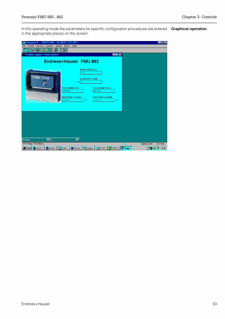
Graphical operationIn this operating mode the parameters for specific configuration procedures are enteredin the appropriate places on the screen.
Prosonic FMU 860...862 Chapter 3: Controls
Endress+Hauser 33
4 Level, Difference, Average Value
This chapter deals with the basic settings necessary to enable the Prosonic FMU tooperate with the ultrasonic sensor and for you to obtain an indicated measurand rapidly:
• for level measurement or• for the measurement of difference or average value
Setting is carried out in three steps:• Basic settings• Basic adjustment and• Linearization, only necessary for special applications.
Note!As long as the basic settings have not been concluded, the Prosonic FMU emits awarning message. For FMU 862 we recommend that, after the basic settings, channel 1 should first beadjusted and linearized, then channel 2. The matrix positions for channel 2 are on the right of the step-for-step entries.Setting of the analog outputs and the relays is described in chapters 6 and 7. When all parameters have been entered, the matrix can be locked(see chapter 8).After locking, all entries can be displayed, but not altered.
Note the settings When entering the parameters the values entered can be noted in the table on page 111.
4.1 Basic Settings
In detail, the following entries have to be made for the basic setting of the Prosonic FMU:
• Reset the Prosonic FMU. When commissioning for the first time or after replacing the sensor ortransmitter (only during initial commissioning) or after changing between theoperating modes flow and level
• Setting the unit of length • Setting the operating mode • Entering the type of sensor or both sensors • Entries regarding external measuring devices (external limit switch, external
temperature sensor)
Note!
Chapter 4: Level, Difference, Average Value Prosonic FMU 860...862
34 Endress+Hauser

Resetting the transmitterDuring initial commissioning a reset to the values preset in the works (known as defaultvalues) should be made.By entering 333 (if operated via PROFIBUS-DP: 1) in matrix field V9H5 the default valuescan be reset.
Step Matrix Entry Meaning1 V9H5 333 Enter the value 333 (for operation via PROFIBUS-DP: 1)2 - »E« Confirm entry
Note!After resetting the transducer:• The length unit is the same as that before the reset• Any curve which has been previously entered by the user remains stored;
the transmitter selects the »linear« mode.
Length unitsThe Prosonic FMU can be set in feet or metres (default). The length unit is changed inmatrix field V8H3.
Step Matrix Entry Meaning 1 V8H3 e.g. 1 1 = feet; 0 = metres (default value)2 - »E« Confirm entry
Caution!• Units of length may only be altered immediately after a reset of the transmitter• After determing the length unit, this can only be altered when all other parameters
are also changed.• Units of length are the same after resetting the Prosonic as before the reset
Setting the operatingmode
Now enter a number in V8H0 for the operating mode:
• 0 = Level measurement in channel 1• 1 = Level measurement in channels 1 and 2• 3 = Level measurement in channel 2 (and rate of flow in channel 1)• 4 = Difference measurement (Level channel 1 - Level channel 2)• 5 = Measurement of average value (1/2(Level channel 1 + Level channel 2))• 10 = Level measurement on Channel 2 and (differential measurement
(Level Channel 1 - Level Channel 2) on Channel 1
Note!• Modes 2 and 3 and 9 for flow measurement are described in chapter 5.• For mode 3 and 9 the channel for measuring rate of flow should be set first. • Modes 7 and 8, simulation of channels 1 and 2, are described in chapter 9.
Step Matrix Entry Meaning 1 V8H0 e.g. 0 Mode 0, level measurement in channel 12 - »E« Confirm entry
Caution!
Note!
Note!
Prosonic FMU 860...862 Chapter 4: Level, Difference, Average Value
Endress+Hauser 35

Specify sensor type(s) Now enter the type of sensor. For two-channel units the types of both sensors must beentered. The ultrasonic echo can not be evaluated for roughly 5 minutes after the entryof the sensor type. During this time (in which the optimum frequency is attained) the lastmeasured value is displayed.
80 = FDU 8080F = FDU 80 F81 = FDU 8181F = FDU 81 F82 = FDU 8283 = FDU 8384 = FDU 8485 = FDU 8586 = FDU 86
Step Matrix Entry Meaning 1 V0H4 e.g. 82 Sensor FDU 82 is connected to channel 1
2 - »E« Confirm entry
With FMU 862 now specify the sensor for channel 2.
3 V4H4 e.g. 82 Sensor FDU 82 is connected to channel 2
4 - »E« Confirm entry
Entries regardingexternal measuringdevices
If an external limit switch or temperature sensor, or both, are connected to the ProsonicFMU, it is necessary to activate the external measurements (see chapter 6 »Analogoutput« and chapter 7 »Relays«).
Limit switchStep Matrix Entry Meaning 1 V8H6 e.g. 2 Limit switch is connected and
should operate at maximum in channel 1 2 - »E« Confirm entry
External temperaturesensor Step Matrix Entry Meaning
1 V8H7 e.g. 1 external temperature sensor is connected and provides atemperature signal for channels 1
2 - »E« Confirm entry
Chapter 4: Level, Difference, Average Value Prosonic FMU 860...862
36 Endress+Hauser
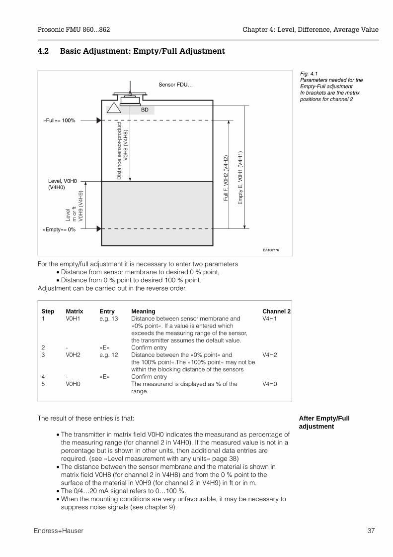
4.2 Basic Adjustment: Empty/Full Adjustment
For the empty/full adjustment it is necessary to enter two parameters• Distance from sensor membrane to desired 0 % point,• Distance from 0 % point to desired 100 % point.
Adjustment can be carried out in the reverse order.
Step Matrix Entry Meaning Channel 21 V0H1 e.g. 13 Distance between sensor membrane and V4H1
»0% point«. If a value is entered whichexceeds the measuring range of the sensor,the transmitter assumes the default value.
2 - »E« Confirm entry3 V0H2 e.g. 12 Distance between the »0% point« and V4H2
the 100% point«.The »100% point« may not be within the blocking distance of the sensors
4 - »E« Confirm entry5 V0H0 The measurand is displayed as % of the V4H0 range.
After Empty/Fulladjustment
The result of these entries is that:
• The transmitter in matrix field V0H0 indicates the measurand as percentage ofthe measuring range (for channel 2 in V4H0). If the measured value is not in apercentage but is shown in other units, then additional data entries arerequired. (see »Level measurement with any units« page 38)
• The distance between the sensor membrane and the material is shown inmatrix field V0H8 (for channel 2 in V4H8) and from the 0 % point to thesurface of the material in V0H9 (for channel 2 in V4H9) in ft or in m.
• The 0/4…20 mA signal refers to 0…100 %.• When the mounting conditions are very unfavourable, it may be necessary to
suppress noise signals (see chapter 9).
BA100Y76
Full
F, V
0H2
(V4H
2)
Em
pty
E, V
0H1
(V4H
1)
»Full« = 100%
»Empty« = 0%
Leve
l m
or
ftV
0H9
(V4H
9)Sensor FDU…
Level, V0H0(V4H0)
Dis
tanc
e se
nsor
-pro
duc
t
V
0H8
(V4H
8)
BD
Fig. 4.1Parameters needed for theEmpty-Full adjustment In brackets are the matrixpositions for channel 2
Prosonic FMU 860...862 Chapter 4: Level, Difference, Average Value
Endress+Hauser 37
Level applications Preset operating values that can be called off and used for various purposes shortencommissioning. By selecting only one application parameter the measuring line isautomatically adapted to suit one of five typical applications. The level applications canbe selected in matrix position V0H3.
• 0 = Liquid• 1 = Liquid, application with rapid change in level• 2 = fine-grained solids• 3 = coarse-grained solids• 4 = conveyor belt loading (solids, application with rapid change in level)
The effects of the various applications on the ultrasonic measurement are described inAppendix B.
Step Matrix Entry Meaning Channel 21 V0H3 e.g. 1 Level application »rapid liquids« V4H3
is selected2 - »E« Confirm entry
Actual level V2H1 When the measuring task demands high accuracy, the entry of an »Actual level«enhances the accuracy. The exact level is, for example, measured with a dip stick andthen entered in V2H1.
Step Matrix Entry Meaning Channel 21 V2H1 e.g. 2.46 Actual level is 2.46 m V5H12 - »E« Confirm entry
Display of height inmeters or feet
The level height in metres (or feet, depending on the original setting) can be displayedin matrix field V0H9 (V4H9 for channel 2).
Level measurement withany units
The following entries are only necessary when no linearization is made afterwards. If the measurand in V0H0 is not to be indicated in % but in some other unit, the full scalevalue required is entered in V2H7. With these entries, for example, the contents or volumeof a vertical, cylindrical tank can be measured. Below the term »volume« is used in theentry steps. Replace it by the numerical value of your unit of measurement.
Step Matrix Entry Meaning Channel 2 1 V2H7 e.g. 750 Enter volume 750 m3 at 100% V5H72 - »E« Confirm entry3 V2H0 0 Activate linearization »linear« V5H04 - »E« Confirm entry
Note!A reset does not automatically set the display to a percentage! If the display is to returnto a percentage, then »100« must be entered in V2H7 for 0…100 %.Note!
Chapter 4: Level, Difference, Average Value Prosonic FMU 860...862
38 Endress+Hauser

Measurand indicationThe measurand for channel 1 is indicated by V0H0 (channel 2 by V4H0). In addition,some matrix fields contain information on the system, e.g. for fault analysis, etc.Table 4.1 summarizes the displayed and measured values.
Matrix Measurand Note
V0H0V4H0
Level or volume Indicated in %, hl, m3, ft3, t dependent ofwether a linearization has been activated
V0H8V4H8
Distance: Sensor - productsurface
The distance between sensor and productsurface in m or ft V0H8 for channel 1, V4H8 for channel 2
V0H9V4H9
Level indication of level in m or ftV0H9 for channel 1, V4H9 for channel 2
V3H1V6H1
Echo attenuation db The echo attenuation between emission andreception by the sensor V3H1 for channel 1, V6H1 for channel 2
V3H2V6H2
Signal-noise ratio Signal-noise ratio: The difference between auseful signal (echo) and a noise signal. Thehigher this ratio is the better the echo can beevaluated (10 dB or lager is acceptable).
V8H8 Internal counter high The first four digits of the eight digit softwarecounter are displayed.
V8H9 Internal counter low The last four digits of the eight digit softwarecounter are displayed.
V9H0 Diagnostic code The current diagnostic code can be read off
V9H1 Last diagnostic code The last diagnostic code can be read off anddeleted.
V9H2 Last diagnostic code but one The last diagnostic code but one can be readoff and deleted.
V9H3 Unit code withSoftware version
The first two figures are the unit code, the lasttwo are the software number
Tab. 4.1Measurand indication
Prosonic FMU 860...862 Chapter 4: Level, Difference, Average Value
Endress+Hauser 39
4.3 Linearization
In tanks and vessels in which the volume is not directly proportional to the level, a levelmeasurement is converted into a volume measurement by linearization. The parametersof linearization are entered in matrix line V2 for channel 1 and line V5 for channel 2. Thetypes of linearization, horizontal, cylindrical tank and tank with conical outlet, aredescribed in sections 4.3 and 4.4.
The following linearizations can be selected in V2H0:
0 = linear (default) 1 = horizontal cylindrical3 = manual entry4 = automatic entry 5 = delete
After linearization After linearization
• In V0H0 the volume in the tank or silo can be read (V4H0 for channel 2).• In V0H9 the level can be read (V4H9 for channel 2).• The switching points of the relays must be set in accordance with the volume
units.• Analogue outputs: confisure the analogue outputs accordingly.
Two important rules for linearization must be observed:
• Linearization zeroThe level entries for linearization and the level entry for the empty adjustmentmust both refer to the same zero point.
• Units of measurement:For all level entries the numerical values must always refer to the same unit oflength, as defined in V8H3.Also for all volume entries the numerical values entered must always refer tothe same dimensional unit. For example, all values entered for volume mustbe in litres, hl or other unit.
Caution!• When manual entries are made, always delete the old linearization (V2H0=5), before
entering new points.• If the linearization limit is exceeded or dropped below::
The curve is extrapolated downwards (upwards) by a maximum 10% with the firsttwo (or last two) points.
Caution!
Chapter 4: Level, Difference, Average Value Prosonic FMU 860...862
40 Endress+Hauser
Switch off linearization »linear«
The setting »linear« in the matrix field Linearization V2H0 is used when the linearizationhas to be switched off for measuring level as a percentage of total level. The linearizationtable is still in the memory, but no longer active.
Step Matrix Entry Meaning1 V2H0 0 Choose linearization »linear« 2 - »E« Confirm entry
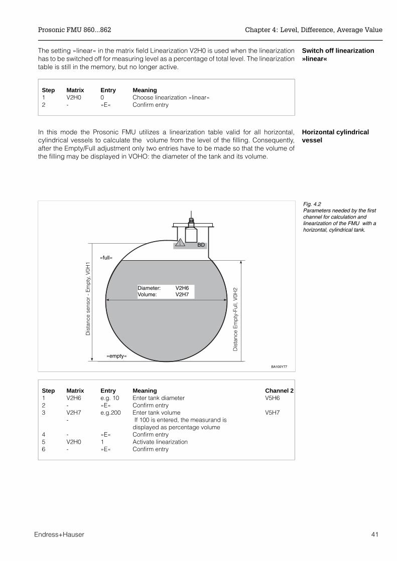
Horizontal cylindricalvessel
In this mode the Prosonic FMU utilizes a linearization table valid for all horizontal,cylindrical vessels to calculate the volume from the level of the filling. Consequently,after the Empty/Full adjustment only two entries have to be made so that the volume ofthe filling may be displayed in VOHO: the diameter of the tank and its volume.
Step Matrix Entry Meaning Channel 21 V2H6 e.g. 10 Enter tank diameter V5H62 - »E« Confirm entry3 V2H7 e.g.200 Enter tank volume V5H7
- If 100 is entered, the measurand isdisplayed as percentage volume
4 - »E« Confirm entry5 V2H0 1 Activate linearization6 - »E« Confirm entry
Dis
tanc
e E
mp
ty-F
ull,
V0H
2
Dis
tanc
e se
nsor
- E
mp
ty, V
0H1
»full«
»empty«
Diameter: V2H6Volume: V2H7
BA100Y77
BD
Fig. 4.2Parameters needed by the firstchannel for calculation andlinearization of the FMU with ahorizontal, cylindrical tank.
Prosonic FMU 860...862 Chapter 4: Level, Difference, Average Value
Endress+Hauser 41

4.4 Linearization for Vessels of Any Shape
The linearization modes »manual« and »semiautomatic« are set to measure the volumeof vessels which are not horizontal cylinders. A widespread example of such vessels isa tank with conical outlet. To measure the volume in such vessels the Prosonic FMUutilizes a table, in which the volume is stored for several levels. This table can be enteredby hand.
The pairs of values in the table (volume/level) can be found in two ways and entered:• when the level/volume ratio is known Linearization mode »Manual«:
All pairs of values (volume/level) are entered from an existing table or a curvesupplied by the tank manufacturer.
• when the level/volume ratio is unknown: filling the tank with known amount ofliquids. »Automatic« linearization modeThe following procedure has to be repeated several times: The tank is filledand the volume is measured (e.g. with a flow measuring unit). The measurandfor the volume is entered in V2H4. The associated level is registeredautomatically. This procedure is repeated several times with differentquantities, where possible uniformly spread over the whole range from emptyto full vessel.
Dis
tanc
e »E
mp
ty«
- »F
ull«
, V0H
2
Dis
tanz
sen
sor
- »E
mp
ty«,
V0H
1
Level in m orfeet
Volume
0/4…20 mA signal
Leve
l poi
nts
BA100Y78
BD
Fig. 4.3Parameters needed forlinearization and the matrix fieldsfor channel 1
Chapter 4: Level, Difference, Average Value Prosonic FMU 860...862
42 Endress+Hauser

Note!• It is reasonable to enter at least three points.
With the first pair of values the smallest volume to be measured and thecorresponding level should be entered.With the last pair of values the largest volume to be measured and thecorresponding level should be entered.
• The more pairs of values you enter, the more exact is linearization. You can enter amaximum of 32 pairs of values.
• Having activated linearization, the points are sorted according to rising level andsubjected to a plausibility check.
• After entering the point number the assigned pair of values, level and flow, can bedisplayed.
Note!
Prosonic FMU 860...862 Chapter 4: Level, Difference, Average Value
Endress+Hauser 43
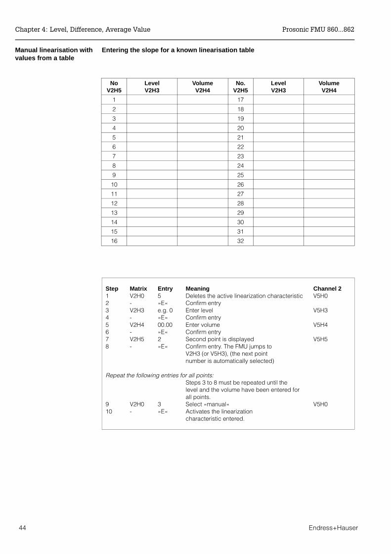
Manual linearisation withvalues from a table
Entering the slope for a known linearisation table
NoV2H5
LevelV2H3
VolumeV2H4
No.V2H5
LevelV2H3
VolumeV2H4
1 17
2 18
3 19
4 20
5 21
6 22
7 23
8 24
9 25
10 26
11 27
12 28
13 29
14 30
15 31
16 32
Step Matrix Entry Meaning Channel 21 V2H0 5 Deletes the active linearization characteristic V5H02 - »E« Confirm entry3 V2H3 e.g. 0 Enter level V5H34 - »E« Confirm entry5 V2H4 00.00 Enter volume V5H4 6 - »E« Confirm entry7 V2H5 2 Second point is displayed V5H58 - »E« Confirm entry. The FMU jumps to
V2H3 (or V5H3), (the next pointnumber is automatically selected)
Repeat the following entries for all points:Steps 3 to 8 must be repeated until thelevel and the volume have been entered for
all points.9 V2H0 3 Select »manual« V5H010 - »E« Activates the linearization characteristic entered.
Chapter 4: Level, Difference, Average Value Prosonic FMU 860...862
44 Endress+Hauser
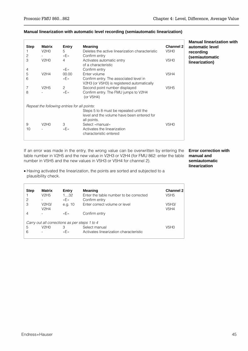
Manual linearization with automatic level recording (semiautomatic linearization)
Manual linearization withautomatic levelrecording (semiautomaticlinearization)
Step Matrix Entry Meaning Channel 21 V2H0 5 Deletes the active linearization characteristic V5H02 - »E« Confirm entry3 V2H0 4 Activates automatic entry V5H0
of a characteristic4 »E« Confirm entry5 V2H4 00.00 Enter volume V5H4 6 »E« Confirm entry. The associated level in
V2H3 (or V5H3) is registered automatically7 V2H5 2 Second point number displayed V5H58 - »E« Confirm entry. The FMU jumps to V2H4
(or V5H4)
Repeat the following entries for all points:Steps 5 to 8 must be repeated until thelevel and the volume have been entered for
all points. 9 V2H0 3 Select »manual« V5H010 - »E« Activates the linearization
characteristic entered
Error correction withmanual andsemiautomaticlinearization
If an error was made in the entry, the wrong value can be overwritten by entering thetable number in V2H5 and the new value in V2H3 or V2H4 (for FMU 862: enter the tablenumber in V5H5 and the new values in V5H3 or V5H4 for channel 2).
• Having activated the linearization, the points are sorted and subjected to aplausibility check.
Step Matrix Entry Meaning Channel 21 V2H5 1…32 Enter the table number to be corrected V5H52 - »E« Confirm entry3 V2H3/ e.g. 10 Enter correct volume or level V5H3/
V2H4 V5H44 - »E« Confirm entry
Carry out all corrections as per steps 1 to 4 5 V2H0 3 Select manual V5H06 - »E« Activates linearization characteristic
Prosonic FMU 860...862 Chapter 4: Level, Difference, Average Value
Endress+Hauser 45
Deleting a characteristic All values in a linearization table can be deleted in one step; in the matrix field V2H0 forselection of linearization the setting »cancel« must be selected and confirmed.
Step Matrix Entry Meaning Channel 21 V2H0 »5« Select linearization »cancel« V5H02 - »E« Characteristic deleted 3 V2H0 e.g. 1 Level, select horizontal cylindrical V5H0
as new mode4 - »E« Confirm entry
Note!If a different linearizations mode is selected, the characteristic entered manually orsemiautomatic remains stored in the Prosonic FMU, without being used. If linearization»manual« is later re-selected, the measuring properties of the Prosonic FMU are thesame as before.
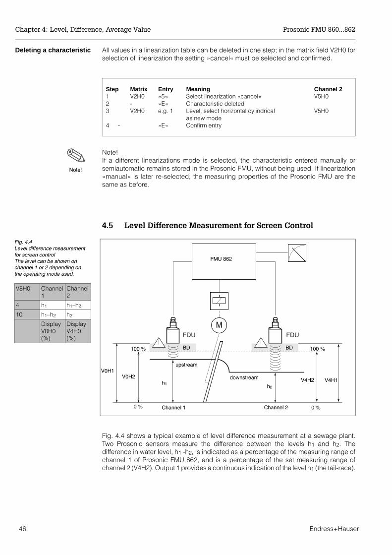
4.5 Level Difference Measurement for Screen Control
Fig. 4.4 shows a typical example of level difference measurement at a sewage plant.Two Prosonic sensors measure the difference between the levels h1 and h2. Thedifference in water level, h1 -h2, is indicated as a percentage of the measuring range ofchannel 1 of Prosonic FMU 862, and is a percentage of the set measuring range ofchannel 2 (V4H2). Output 1 provides a continuous indication of the level h1 (the tail-race).
0 %
Note!
FMU 862
V4H1h1
Channel 1
upstream
100 %
0 %Channel 2
V4H2
V0H1V0H2
h2
downstream
100 % BD BD
Fig. 4.4Level difference measurementfor screen controlThe level can be shown onchannel 1 or 2 depending onthe operating mode used.
V8H0 Channel 1
Channel 2
4 h1 h1–h2
10 h1–h2 h2
DisplayV0H0(%)
DisplayV4H0(%)
Chapter 4: Level, Difference, Average Value Prosonic FMU 860...862
46 Endress+Hauser
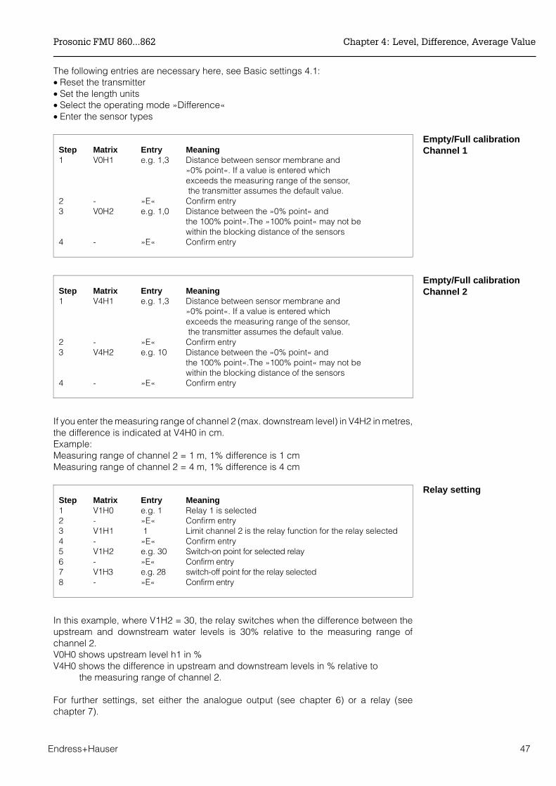
The following entries are necessary here, see Basic settings 4.1:• Reset the transmitter• Set the length units• Select the operating mode »Difference«• Enter the sensor types
Empty/Full calibrationChannel 1Step Matrix Entry Meaning
1 V0H1 e.g. 1,3 Distance between sensor membrane and »0% point«. If a value is entered whichexceeds the measuring range of the sensor, the transmitter assumes the default value.
2 - »E« Confirm entry3 V0H2 e.g. 1,0 Distance between the »0% point« and
the 100% point«.The »100% point« may not be within the blocking distance of the sensors
4 - »E« Confirm entry
Empty/Full calibrationChannel 2Step Matrix Entry Meaning
1 V4H1 e.g. 1,3 Distance between sensor membrane and »0% point«. If a value is entered whichexceeds the measuring range of the sensor, the transmitter assumes the default value.
2 - »E« Confirm entry3 V4H2 e.g. 10 Distance between the »0% point« and
the 100% point«.The »100% point« may not be within the blocking distance of the sensors
4 - »E« Confirm entry
If you enter the measuring range of channel 2 (max. downstream level) in V4H2 in metres,the difference is indicated at V4H0 in cm.Example:Measuring range of channel 2 = 1 m, 1% difference is 1 cmMeasuring range of channel 2 = 4 m, 1% difference is 4 cm
Relay settingStep Matrix Entry Meaning 1 V1H0 e.g. 1 Relay 1 is selected2 - »E« Confirm entry3 V1H1 1 Limit channel 2 is the relay function for the relay selected4 - »E« Confirm entry5 V1H2 e.g. 30 Switch-on point for selected relay6 - »E« Confirm entry7 V1H3 e.g. 28 switch-off point for the relay selected8 - »E« Confirm entry
In this example, where V1H2 = 30, the relay switches when the difference between theupstream and downstream water levels is 30% relative to the measuring range ofchannel 2.V0H0 shows upstream level h1 in %V4H0 shows the difference in upstream and downstream levels in % relative to the measuring range of channel 2.
For further settings, set either the analogue output (see chapter 6) or a relay (seechapter 7).
Prosonic FMU 860...862 Chapter 4: Level, Difference, Average Value
Endress+Hauser 47
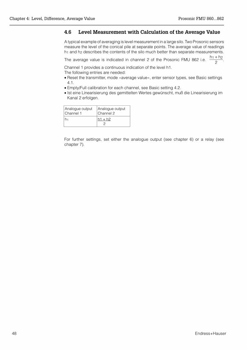
4.6 Level Measurement with Calculation of the Average Value
A typical example of averaging is level measurement in a large silo. Two Prosonic sensorsmeasure the level of the conical pile at separate points. The average value of readingsh1 and h2 describes the contents of the silo much better than separate measurements.
The average value is indicated in channel 2 of the Prosonic FMU 862 i.e. h1 + h2
2.
Channel 1 provides a continuous indication of the level h1. The following entries are needed: • Reset the transmitter, mode »average value«, enter sensor types, see Basic settings
4.1.• Empty/Full calibration for each channel, see Basic setting 4.2.• Ist eine Linearisierung des gemittelten Wertes gewünscht, muß die Linearisierung im
Kanal 2 erfolgen.
Analogue outputChannel 1
Analogue outputChannel 2
h1 h1 + h2 2
For further settings, set either the analogue output (see chapter 6) or a relay (seechapter 7).
Chapter 4: Level, Difference, Average Value Prosonic FMU 860...862
48 Endress+Hauser

5 Flow
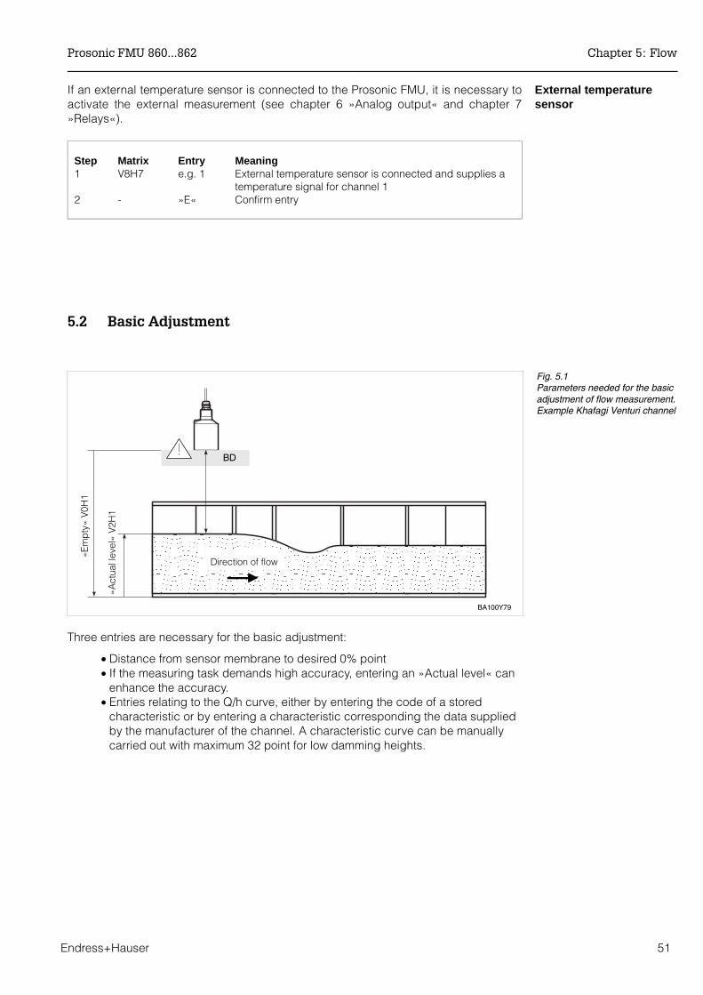
This chapter describes the basic settings for flow measurement which are necessary inorder that Prosonic FMU may operate with the ultrasonic sensor so that a displayedmeasurand is rapidly obtained. Setting is carried out in three steps:
• Basic setting• Basic adjustment and• Setting the totalisers
Note!As long as the basic setting has not been concluded, the Prosonic FMU emits a warning.With FMU 862 we advise you to adjust and linearize channel 1 first after the basic setting(for channel 2 see chapter 4.2).
Setting of the analog outputs and the relays is described in chapters 6 and 7.Having entered all parameters, the matrix can be locked (see chapter 8).After locking, all entries can be displayed, but not altered.
Note the settingsWhen entering the parameters the values entered can be noted in the table on page 111.
5.1 Basic Settings
In detail the following entries are needed for the basic setting of the Prosonic FMU.
• Reset the Prosonic FMU, also after changing between the operating modesflow and level
• Setting the length unit • Setting the operating mode • Entering the type of sensor or for FMU 862 both sensors • Entries relating to external measuring devices (external limit switch, external
temperature sensor)
Reset the transducer The first time the unit is commissioned, it should be reset to the values (default) set inthe works.By entering 333 (for operation via PROFIBUS-DP: 1) in matrix field V9H5 the unit is resetto the default values.
Step Matrix Entry Meaning 1 V9H5 333 Enter the value 333 (for operation via PROFIBUS-DP: 1)2 - »E« Confirm entry
Note!After resetting the transducer:• The length unit is the same as that before the reset• Any curve which has been previously entered by the user remains stored;
the transmitter selects the »linear« mode.
Note!
Note!
Prosonic FMU 860...862 Chapter 5: Flow
Endress+Hauser 49

Length units The Prosonic FMU can be set in metres (default) or feet. The change of length unit ismade in matrix field V8H3.
Step Matrix Entry Meaning 1 V8H3 e.g. 1 1 = feet; 0 = metres (default value)2 - »E« Confirm entry
Caution!• Units of length may only be altered immediately after a reset of the transmitter.• After determining the length units, this can only be altered when all other
parameters are also changed.• The length units are exactly the same after resetting the Prosonic as before the
reset.
Setting the operatingmode
Now enter a number in V8H0 for the mode:
• 2 = Flow measurement in channel 1• 3 = Flow measurement in channel 1 (Level measurement in channel 2)• 9 = Flow measurement with back pressure determination
Note!The modes 7 and 8, Simulation channel 1 and channel 2, are described in chapter 9. Allother modes are described in chapter 4.
Step Matrix Entry Meaning 1 V8H0 e.g. 2 Mode 2, Flow measurement 2 - »E« Confirm entry
Specify sensor type(s) Now specify the sensor type. For two-channel units both sensors must be specified.
80 = FDU 8080F = FDU 80 F81 = FDU 8181F = FDU 81 F82 = FDU 8283 = FDU 8384 = FDU 8485 = FDU 8586 = FDU 86
Step Matrix Entry Meaning 1 V0H4 e.g. 80 Sensor FDU 80 is connected to channel 1
»E« Confirm entry For FMU 862 specify the sensor for channel 2 as well
3 V4H4 e.g. 80 Sensor FDU 80 is connected to channel 24 - »E« Confirm entry
Caution!
Note!
Chapter 5: Flow Prosonic FMU 860...862
50 Endress+Hauser
External temperaturesensor
If an external temperature sensor is connected to the Prosonic FMU, it is necessary toactivate the external measurement (see chapter 6 »Analog output« and chapter 7»Relays«).
Step Matrix Entry Meaning 1 V8H7 e.g. 1 External temperature sensor is connected and supplies a
temperature signal for channel 12 - »E« Confirm entry
5.2 Basic Adjustment
Three entries are necessary for the basic adjustment:
• Distance from sensor membrane to desired 0% point• If the measuring task demands high accuracy, entering an »Actual level« can
enhance the accuracy.• Entries relating to the Q/h curve, either by entering the code of a stored
characteristic or by entering a characteristic corresponding the data suppliedby the manufacturer of the channel. A characteristic curve can be manuallycarried out with maximum 32 point for low damming heights.
BA100Y79
»Act
ual l
evel
« V
2H1
»Em
pty
« V
0H1
BD
Direction of flow
Fig. 5.1Parameters needed for the basicadjustment of flow measurement.Example Khafagi Venturi channel
Prosonic FMU 860...862 Chapter 5: Flow
Endress+Hauser 51

The effect of these entries is that: • the transmitter in matrix field V0H0 indicates the rate of flow. • the distance between the sensor membrane and the water-level can be read
in m or ft in matrix field V0H8 and the water-level itself in V0H9.
Adjustment »Empty«Step Matrix Entry Meaning1 V0H1 e.g. 1.8 Distance between sensor membrane and »0% point«2 - »E« Confirm entry
Actual level V2H1 If the measuring task demands high accuracy, the results of measurement can beimproved by entering an »Actual level«.
Step Matrix Entry Meaning 1 V2H1 e.g. 1.463 The actual level is 1.463 m2 - »E« Confirm entry
Calling Up a Q/h CurveThe calculation performed by the Prosonic FMU converts the level measurement in theflume into a flow measurement. For this conversion a Q/h curve is needed.• These characteristics are memorised for the weirs or flumes and the right one has to
be activated by specifying a characteristic number. All available characteristics canbe found in Appendix A.
• If the characteristic of your channel is not listed, the characteristic can be enteredfrom a table drawn up by the manufacturer of the weir or flume.
Step Matrix Entry Meaning1 V2H2 e.g. 2 Select number of Q/h characteristic2 - »E« Confirm entry3 V2H0 e.g. 2 Activate linearization type of Q/h curve4 - »E« Confirm entry5 V0H0 - Rate of flow is displayed
Entering a characteristic curve code determines the maximum flowrate Qmax. If thechannel is only used in the lower range, then you can enter the actual maximum flow. Allother entries (e.g. for current output) are then functions of the value entered (in V2H7).
Step Matrix Entry Meaning1 V2H7 e.g. 900 The actual maximum flowrate is 900 m3/h2 - ”E” Confirm input
Note!After entering the curve (in V2H2), we recommend that the current output is calibrated,e.g. the value for Qmax can be enetered in VoH6, if the 20 mA current signal is for thisflowrate (default value in VoH6: 100 m3/h). The preset Q/h curves (see Appendix A)always have the flow unit m3/h.If you afterwards alter the flow units, the analogue output (see chapter 6) and the relayswith the function »Limit value« must be set afresh (see chapter 7).
Note!
Chapter 5: Flow Prosonic FMU 860...862
52 Endress+Hauser
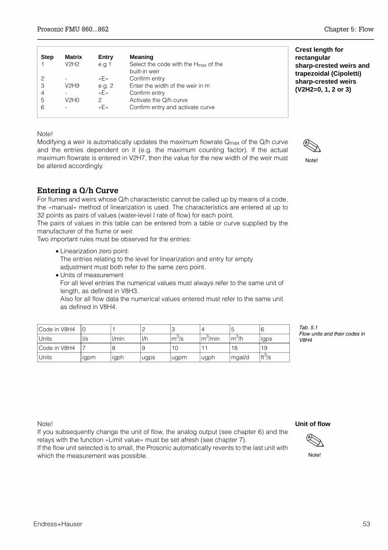
Crest length forrectangularsharp-crested weirs andtrapezoidal (Cipoletti)sharp-crested weirs(V2H2=0, 1, 2 or 3)
Step Matrix Entry Meaning1 V2H2 e.g 1 Select the code with the Hmax of the
built-in weir2 - »E« Confirm entry3 V2H9 e.g. 2 Enter the width of the weir in m4 - »E« Confirm entry5 V2H0 2 Activate the Q/h curve6 - »E« Confirm entry and activate curve
Note!Modifying a weir is automatically updates the maximum flowrate Qmax of the Q/h curveand the entries dependent on it (e.g. the maximum counting factor). If the actualmaximum flowrate is entered in V2H7, then the value for the new width of the weir mustbe altered accordingly.
Entering a Q/h CurveFor flumes and weirs whose Q/h characteristic cannot be called up by means of a code,the »manual« method of linearization is used. The characteristics are entered at up to32 points as pairs of values (water-level | rate of flow) for each point. The pairs of values in this table can be entered from a table or curve supplied by themanufacturer of the flume or weir.Two important rules must be observed for the entries:
• Linearization zero point:The entries relating to the level for linearization and entry for emptyadjustment must both refer to the same zero point.
• Units of measurementFor all level entries the numerical values must always refer to the same unit oflength, as defined in V8H3.Also for all flow data the numerical values entered must refer to the same unitas defined in V8H4.
Unit of flowNote!If you subsequently change the unit of flow, the analog output (see chapter 6) and therelays with the function »Limit value« must be set afresh (see chapter 7). If the flow unit selected is to small, the Prosonic automatically revents to the last unit withwhich the measurement was possible.
Note!
Note!
Code in V8H4 0 1 2 3 4 5 6
Units l/s l/min l/h m3/s m3/min m3/h igps
Code in V8H4 7 8 9 10 11 18 19
Units igpm igph ugps ugpm ugph mgal/d ft3/s
Tab. 5.1Flow units and their codes inV8H4
Prosonic FMU 860...862 Chapter 5: Flow
Endress+Hauser 53
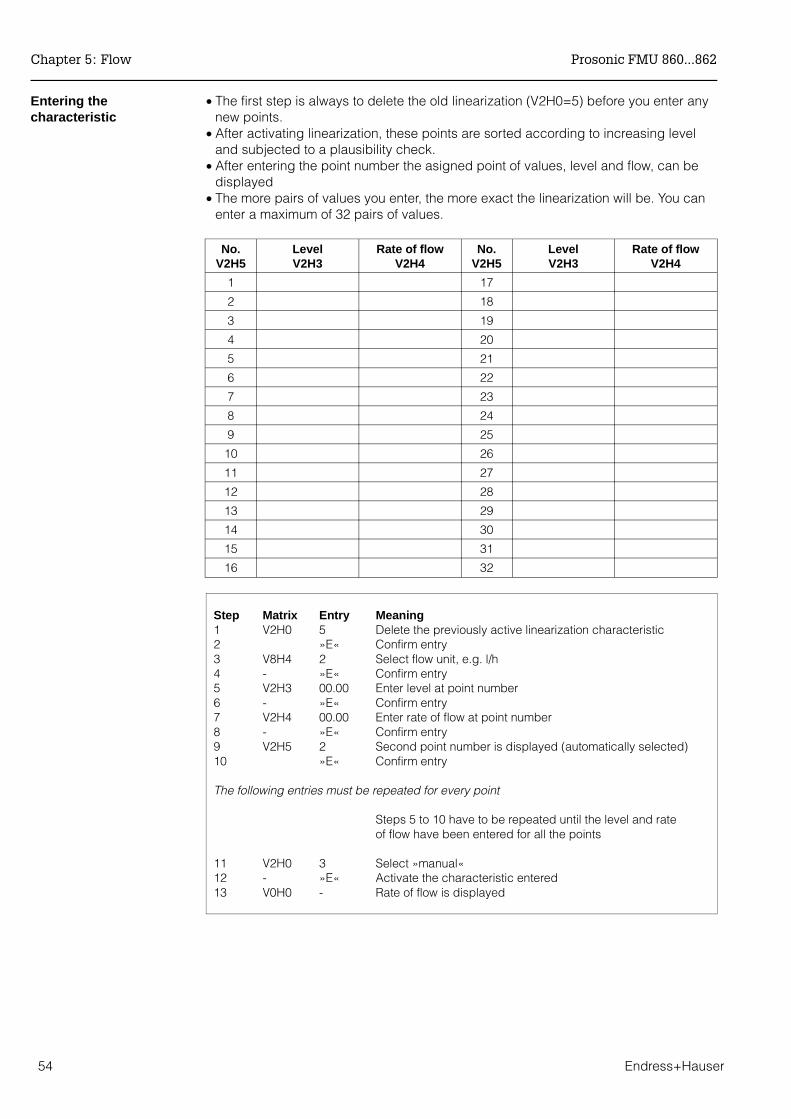
Entering thecharacteristic
• The first step is always to delete the old linearization (V2H0=5) before you enter anynew points.
• After activating linearization, these points are sorted according to increasing leveland subjected to a plausibility check.
• After entering the point number the asigned point of values, level and flow, can bedisplayed
• The more pairs of values you enter, the more exact the linearization will be. You canenter a maximum of 32 pairs of values.
No.V2H5
LevelV2H3
Rate of flowV2H4
No.V2H5
LevelV2H3
Rate of flowV2H4
1 17
2 18
3 19
4 20
5 21
6 22
7 23
8 24
9 25
10 26
11 27
12 28
13 29
14 30
15 31
16 32
Step Matrix Entry Meaning1 V2H0 5 Delete the previously active linearization characteristic2 »E« Confirm entry3 V8H4 2 Select flow unit, e.g. l/h4 - »E« Confirm entry5 V2H3 00.00 Enter level at point number6 - »E« Confirm entry7 V2H4 00.00 Enter rate of flow at point number8 - »E« Confirm entry9 V2H5 2 Second point number is displayed (automatically selected)10 »E« Confirm entry
The following entries must be repeated for every point
Steps 5 to 10 have to be repeated until the level and rate of flow have been entered for all the points
11 V2H0 3 Select »manual«12 - »E« Activate the characteristic entered13 V0H0 - Rate of flow is displayed
Chapter 5: Flow Prosonic FMU 860...862
54 Endress+Hauser
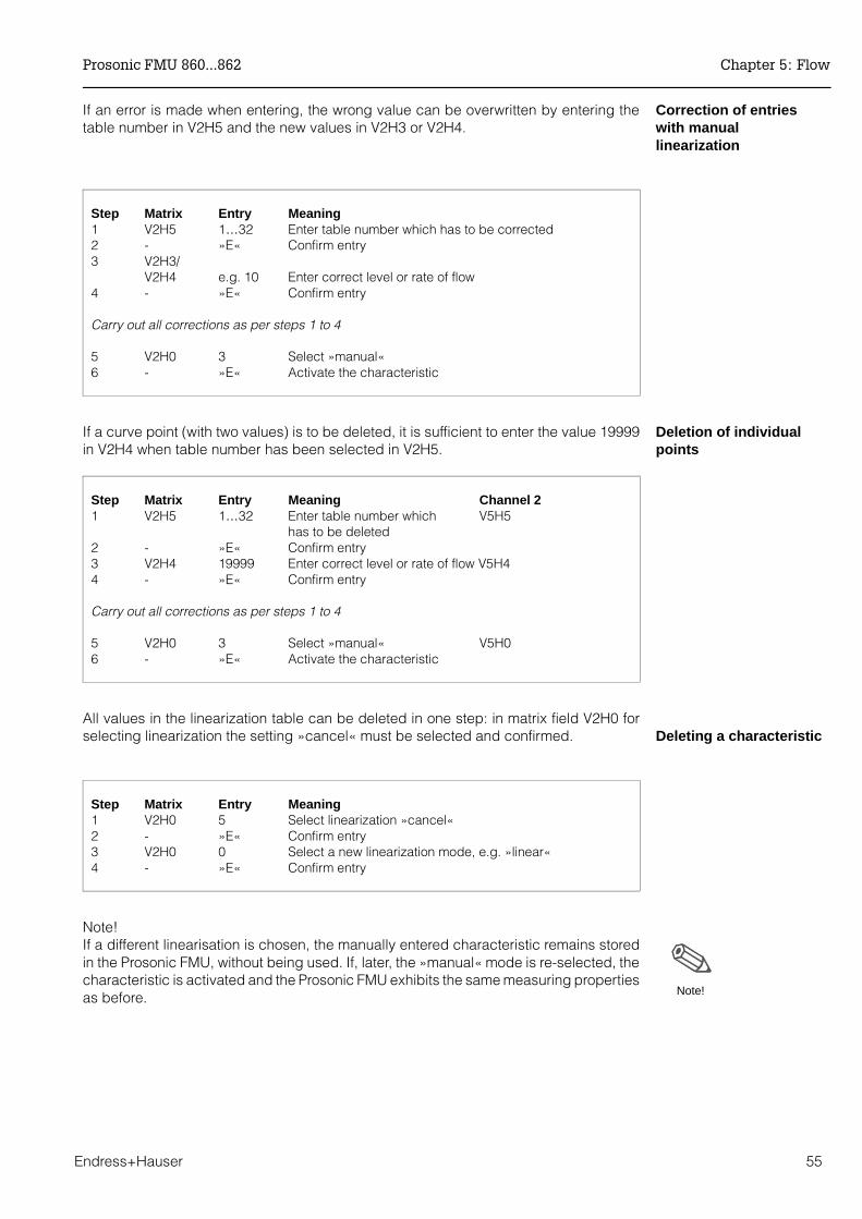
Correction of entrieswith manuallinearization
If an error is made when entering, the wrong value can be overwritten by entering thetable number in V2H5 and the new values in V2H3 or V2H4.
Step Matrix Entry Meaning1 V2H5 1…32 Enter table number which has to be corrected2 - »E« Confirm entry3 V2H3/
V2H4 e.g. 10 Enter correct level or rate of flow 4 - »E« Confirm entry
Carry out all corrections as per steps 1 to 4
5 V2H0 3 Select »manual« 6 - »E« Activate the characteristic
Deletion of individualpoints
If a curve point (with two values) is to be deleted, it is sufficient to enter the value 19999in V2H4 when table number has been selected in V2H5.
Step Matrix Entry Meaning Channel 21 V2H5 1…32 Enter table number which V5H5
has to be deleted2 - »E« Confirm entry3 V2H4 19999 Enter correct level or rate of flow V5H4 4 - »E« Confirm entry
Carry out all corrections as per steps 1 to 4
5 V2H0 3 Select »manual« V5H06 - »E« Activate the characteristic
Deleting a characteristicAll values in the linearization table can be deleted in one step: in matrix field V2H0 forselecting linearization the setting »cancel« must be selected and confirmed.
Step Matrix Entry Meaning 1 V2H0 5 Select linearization »cancel«2 - »E« Confirm entry3 V2H0 0 Select a new linearization mode, e.g. »linear«4 - »E« Confirm entry
Note!If a different linearisation is chosen, the manually entered characteristic remains storedin the Prosonic FMU, without being used. If, later, the »manual« mode is re-selected, thecharacteristic is activated and the Prosonic FMU exhibits the same measuring propertiesas before. Note!
Prosonic FMU 860...862 Chapter 5: Flow
Endress+Hauser 55

Measurand indication The measurand for channel 1 is shown by V0H0 (for channel 2 V4H0). In addition, certainmatrix fields show system information, e.g. for fault analysis, etc.Table 5.2. summarizes the indicated and measured values.
Matrix Measurand Note
V0H0(V4H0)
Rate of flow(Level or volume)
Display in units of V8H4 or customers unitV0H0 for channel 1(V4H0 level measurement for channel 2)
V0H8(V4H8)
Distance: Sensor - productsurface
The distance between sensor and productsurface in m or ft V0H8 for channel 1, V4H8 for channel 2
V0H9(V4H9)
Level indication of level in m or ft V0H9 for channel 1, V4H9 for channel 2
V3H1(V6H1)
Echo attenuation db The echo attenuation between emission andreception by the sensor V3H1 for channel 1, V6H1 for channel 2
V3H2(V6H2)
Signal-noise ratio Signal-noise ratio: The difference between auseful signal (echo) and a noise signal. Thehigher this ratio is the better the echo can beevaluated (10 dB or larger is acceptable).
V8H8 Internal counter high The first four digits of the eight digit softwarecounter are displayed.
V8H9 Internal counter low The last four digits of the eight digit softwarecounter are displayed.
V9H0 Diagnostic code The current diagnostic code can be read off
V9H1 Last diagnostic code The last diagnostic code can be read off anddeleted.
V9H2 Last diagnostic code but one The last diagnostic code but one can be readoff and deleted.
V9H3 Unit code with software version
The first two figures are the unit code, the lasttwo are the software number
Tab. 5.2Measurand indicationValues in brackets apply toChannel 2
Chapter 5: Flow Prosonic FMU 860...862
56 Endress+Hauser

5.3 Setting the Totalizers
The Prosonic FMU possesses a software totalizer and an optional totalizer unit todetermine the rate of flow. The totalizers switch in terms of
• the voluminar flow• the counting unit (V8H5) and • the counting factors.
The software totalizer and the optional totalizer unit are influenced by the adjustable lowflow cut off in V2H8. Only the software totalizer can be reset. The first four figures of theeight digit software counter are shown by V8H8, the last four by V8H9. External totalizercan be controlled by the relays (see chapter 7.4).
Note!When connecting an external totaliser, please note:The maximum counting frequency of the Prosonic FMU 86_ is 2 Hz, the pulse width is200 msec. To ensure that all counting pulses are fully picked up, the counting frequencyof the external totaliser must be adjusted to these values.
Counting formulaWe write:Total volume = Total number of counting pulses x counting factor x counting unit
Counting unitThe set counting unit (V8H5) applies to all counters. Table 5.3 lists all the counting unitsand their code numbers in field V8H5.
Step Matrix Entry Meaning 1 V8H5 2 m3 was chosen as counting unit2 - »E« Confirm entry
Counting factors The counting factor Z2 in V1H6 is used for the software counter.The counting factor Z1 in V1H5 is used for the optionally connected totaliser.Any value may be entered as counting factors in matrix fields V1H5 and V1H6. If amaximum value of 19999 is exceeded (e.g. after selecting a new Q/h curve), or thecounting pulse rate is larger than 2 counting pulses per second with maximum flowrate,then the Prosonic counting factors are automatically adjusted. The warning messageE 620 is displayed and the corrected counting factors in V1H5 and V1H6 can beconfirmed. If no correction using the selected counting units is possible, then the warningmessage E 621 is displayed. Other technical units are then to be entered in V8H5.
Step Matrix Entry Meaning 1 V1H5 10 »Counting factor C1« for the totalizer unit
selected and entered as counting factor (e.g 10 m3).2 - »E« Confirm entry
Note!
Counting unit Code in V8H5
l 0
hl 1
m3 2
i gal 5
us gal 6
bls 7
inch3 8
ft3 9
Tab. 5.3Counting units and their codes
Prosonic FMU 860...862 Chapter 5: Flow
Endress+Hauser 57
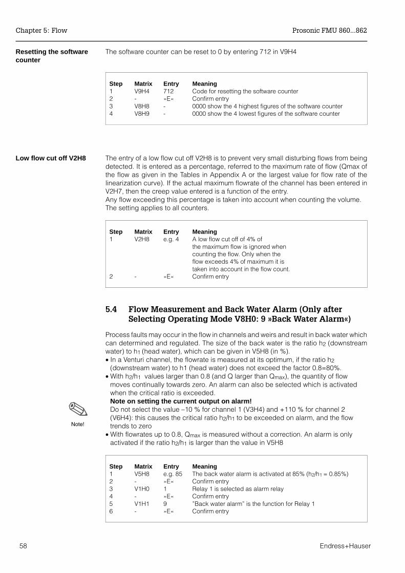
Resetting the softwarecounter
The software counter can be reset to 0 by entering 712 in V9H4
Step Matrix Entry Meaning 1 V9H4 712 Code for resetting the software counter2 - »E« Confirm entry3 V8H8 - 0000 show the 4 highest figures of the software counter4 V8H9 - 0000 show the 4 lowest figures of the software counter
Low flow cut off V2H8 The entry of a low flow cut off V2H8 is to prevent very small disturbing flows from beingdetected. It is entered as a percentage, referred to the maximum rate of flow (Qmax ofthe flow as given in the Tables in Appendix A or the largest value for flow rate of thelinearization curve). If the actual maximum flowrate of the channel has been entered inV2H7, then the creep value entered is a function of the entry.Any flow exceeding this percentage is taken into account when counting the volume.The setting applies to all counters.
Step Matrix Entry Meaning1 V2H8 e.g. 4 A low flow cut off of 4% of
the maximum flow is ignored whencounting the flow. Only when the
flow exceeds 4% of maximum it is taken into account in the flow count.
2 - »E« Confirm entry
5.4 Flow Measurement and Back Water Alarm (Only after Selecting Operating Mode V8H0: 9 »Back Water Alarm«)
Process faults may occur in the flow in channels and weirs and result in back water whichcan determined and regulated. The size of the back water is the ratio h2 (downstreamwater) to h1 (head water), which can be given in V5H8 (in %).• In a Venturi channel, the flowrate is measured at its optimum, if the ratio h2
(downstream water) to h1 (head water) does not exceed the factor 0.8=80%.• With h2/h1 values larger than 0.8 (and Q larger than Qmax), the quantity of flow
moves continually towards zero. An alarm can also be selected which is activatedwhen the critical ratio is exceeded.Note on setting the current output on alarm!Do not select the value –10 % for channel 1 (V3H4) and +110 % for channel 2(V6H4): this causes the critical ratio h2/h1 to be exceeded on alarm, and the flowtrends to zero
• With flowrates up to 0.8, Qmax is measured without a correction. An alarm is onlyactivated if the ratio h2/h1 is larger than the value in V5H8
Step Matrix Entry Meaning1 V5H8 e.g. 85 The back water alarm is activated at 85% (h2/h1 = 0.85%)2 - »E« Confirm entry3 V1H0 1 Relay 1 is selected as alarm relay4 - »E« Confirm entry5 V1H1 9 ”Back water alarm” is the function for Relay 16 - »E« Confirm entry
Note!
Chapter 5: Flow Prosonic FMU 860...862
58 Endress+Hauser
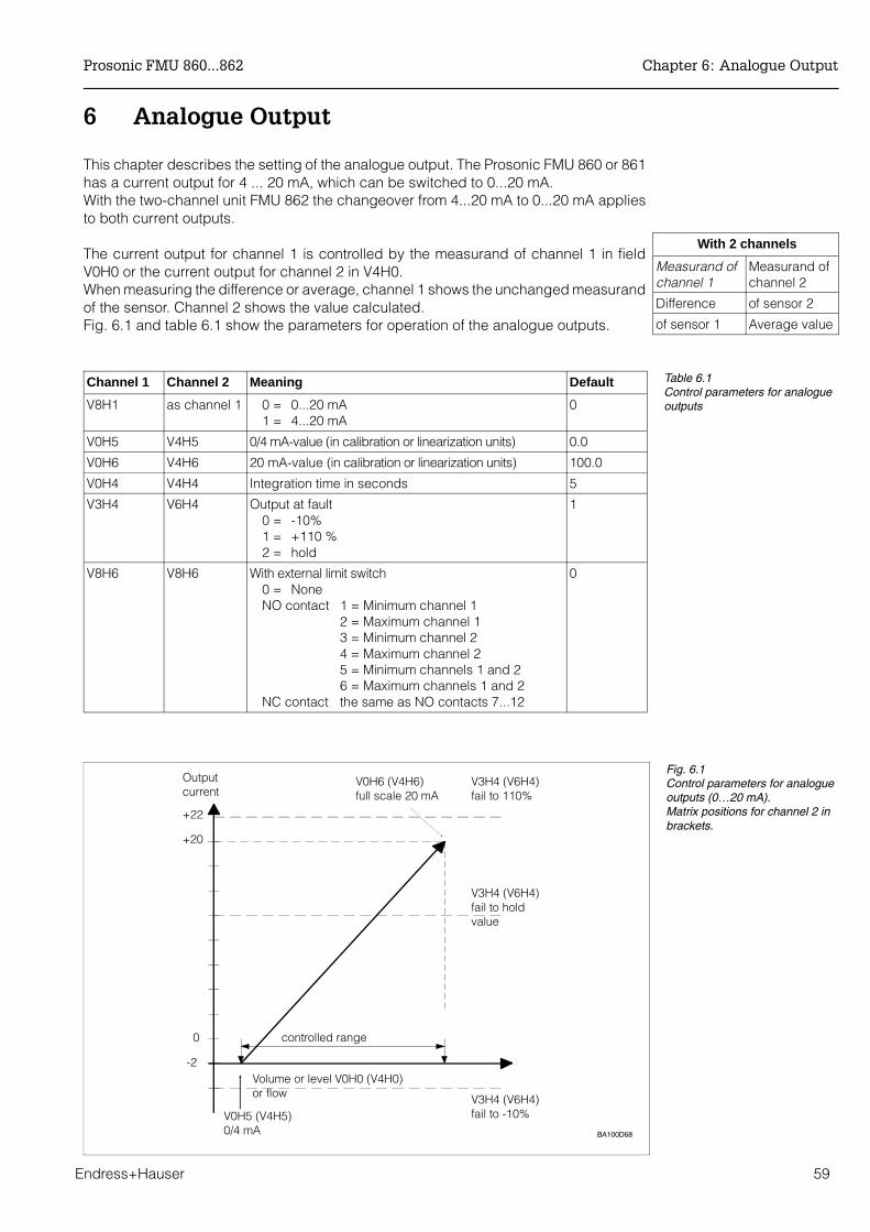
6 Analogue Output
This chapter describes the setting of the analogue output. The Prosonic FMU 860 or 861has a current output for 4 ... 20 mA, which can be switched to 0...20 mA. With the two-channel unit FMU 862 the changeover from 4...20 mA to 0...20 mA appliesto both current outputs.
The current output for channel 1 is controlled by the measurand of channel 1 in fieldV0H0 or the current output for channel 2 in V4H0.When measuring the difference or average, channel 1 shows the unchanged measurandof the sensor. Channel 2 shows the value calculated.Fig. 6.1 and table 6.1 show the parameters for operation of the analogue outputs.
With 2 channels
Measurand ofchannel 1
Measurand ofchannel 2
Difference of sensor 2
of sensor 1 Average value
Channel 1 Channel 2 Meaning Default
V8H1 as channel 1 0 = 0...20 mA 1 = 4...20 mA
0
V0H5 V4H5 0/4 mA-value (in calibration or linearization units) 0.0
V0H6 V4H6 20 mA-value (in calibration or linearization units) 100.0
V0H4 V4H4 Integration time in seconds 5
V3H4 V6H4 Output at fault0 = -10%1 = +110 %2 = hold
1
V8H6 V8H6 With external limit switch0 = NoneNO contact 1 = Minimum channel 1
2 = Maximum channel 1 3 = Minimum channel 2 4 = Maximum channel 2 5 = Minimum channels 1 and 2 6 = Maximum channels 1 and 2
NC contact the same as NO contacts 7...12
0
Table 6.1Control parameters for analogueoutputs
BA100D68
+22
+20
Output current
controlled range
V0H6 (V4H6)full scale 20 mA
V3H4 (V6H4)fail to 110%
V3H4 (V6H4)fail to holdvalue
V0H5 (V4H5)0/4 mA
V3H4 (V6H4)fail to -10%
0
-2Volume or level V0H0 (V4H0)or flow
Fig. 6.1Control parameters for analogueoutputs (0…20 mA).Matrix positions for channel 2 inbrackets.
Prosonic FMU 860...862 Chapter 6: Analogue Output
Endress+Hauser 59

Current output The unit provides two alternatives:
• 0 = 0...20 mA• 1 = 4...20 mA (default)
Entries are made in V8H1. Changing over the current output to 4...20 mA also applies tochannel 2 of FMU 862.
Step Matrix Entry Meaning1 V8H1 1 Select 4 ... 20 mA range2 - »E« Confirm entry
4 mA threshold If a 4...20 mA signal was selected in V8H2 and if the empty adjustment (= 4 mA) wasmade at a definite level, it may happen that signals below 4 mA are generated in normaloperation. If the units connected to the signal line cannot handle signals below 4 mA, it is possibleto define a 4 mA threshold in V8H2, below which the analogue output may not drop.
• 0 = off (default)• 1 = on
Caution!• A 4mA threshold is cancelled on alarm if a response »-10% of measurement
range« is selected in V3H4 for channel 1 or in V6H4 forchannel 2 (see »Output in the event of an alarm«).
• Even if the analogue output is set to 0...20 mA, the signal does not dropbelow the 4 mA threshold.
Step Matrix Entry Meaning1 V8H2 e.g. 1 smallest signal in normal operation = 4 mA, even if
the level drops below the initial measuring range of the analogue signal
»E« Confirm entry.
Setting the analogueoutput
The analogue output parameters assign
• an initial measurand (for level, difference or flow, etc., depending on themode) to the initial value of the current output (0 mA or 4 mA) and
• a final measurand to 20 mA.
Caution!
Chapter 6: Analogue Output Prosonic FMU 860...862
60 Endress+Hauser
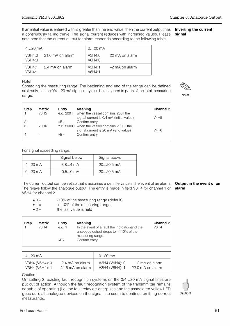
Inverting the currentsignal
If an initial value is entered with is greater than the end value, then the current output hasa continuously falling curve. The signal current reduces with increased values. Pleasenote here that the current output for alarm responds according to the following table.
4…20 mA 0…20 mA
V3H4:0 21.6 mA on alarm V3H4:0 22 mA on alarmV6H4:0 V6H4:0
V3H4:1 2.4 mA on alarm V3H4:1 –2 mA on alarmV6H4:1 V6H4:1
Note!Spreading the measuring range: The beginning and end of the range can be definedarbitrarily, i.e. the 0/4…20 mA signal may also be assigned to parts of the total measuringrange.
Step Matrix Entry Meaning Channel 21 V0H5 e.g. 200 l when the vessel contains 200 l the
signal current is 0/4 mA (initial value) V4H52 - »E« Confirm entry3 V0H6 z.B. 2000 l when the vessel contains 2000 l the signal current is 20 mA (end value) V4H64 - »E« Confirm entry
For signal exceeding range:
Signal below Signal above
4...20 mA 3.8...4 mA 20...20.5 mA
0...20 mA -0.5...0 mA 20...20.5 mA
Output in the event of analarm
The current output can be set so that it assumes a definite value in the event of an alarm.The relays follow the analogue output. The entry is made in field V3H4 for channel 1 orV6H4 for channel 2.
• 0 = -10% of the measuring range (default)• 1 = +110% of the measuring range• 2 = the last value is held
Step Matrix Entry Meaning Channel 21 V3H4 e.g. 1 In the event of a fault the indicationand the V6H4
analogue output drops to +110% of the measuring range
»E« Confirm entry
4...20 mA 0...20 mA
V3H4 (V6H4): 0 2,4 mA on alarm V3H4 (V6H4): 0 -2 mA on alarmV3H4 (V6H4): 1 21.6 mA on alarm V3H4 (V6H4): 1 22.0 mA on alarm
Caution!On setting 2, existing fault recognition systems on the 0/4…20 mA signal lines areput out of action. Although the fault recognition system of the transmmitter remainscapable of operating (i.e. the fault relay de-energizes and the associated yellow LEDgoes out), all analogue devices on the signal line seem to continue emitting correctmeasurands.
Caution!
Note!
Prosonic FMU 860...862 Chapter 6: Analogue Output
Endress+Hauser 61
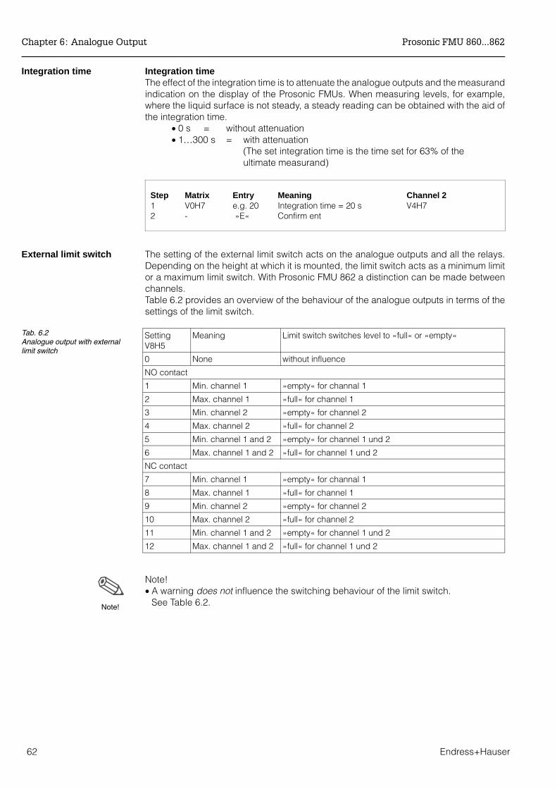
Integration time Integration timeThe effect of the integration time is to attenuate the analogue outputs and the measurandindication on the display of the Prosonic FMUs. When measuring levels, for example,where the liquid surface is not steady, a steady reading can be obtained with the aid ofthe integration time.
• 0 s = without attenuation• 1…300 s = with attenuation
(The set integration time is the time set for 63% of theultimate measurand)
Step Matrix Entry Meaning Channel 21 V0H7 e.g. 20 Integration time = 20 s V4H72 - »E« Confirm ent
External limit switch The setting of the external limit switch acts on the analogue outputs and all the relays.Depending on the height at which it is mounted, the limit switch acts as a minimum limitor a maximum limit switch. With Prosonic FMU 862 a distinction can be made betweenchannels.Table 6.2 provides an overview of the behaviour of the analogue outputs in terms of thesettings of the limit switch.
Note!• A warning does not influence the switching behaviour of the limit switch.
See Table 6.2.
SettingV8H5
Meaning Limit switch switches level to »full« or »empty«
0 None without influence
NO contact
1 Min. channel 1 »empty« for channal 1
2 Max. channel 1 »full« for channel 1
3 Min. channel 2 »empty« for channel 2
4 Max. channel 2 »full« for channel 2
5 Min. channel 1 and 2 »empty« for channel 1 und 2
6 Max. channel 1 and 2 »full« for channel 1 und 2
NC contact
7 Min. channel 1 »empty« for channal 1
8 Max. channel 1 »full« for channel 1
9 Min. channel 2 »empty« for channel 2
10 Max. channel 2 »full« for channel 2
11 Min. channel 1 and 2 »empty« for channel 1 und 2
12 Max. channel 1 and 2 »full« for channel 1 und 2
Tab. 6.2Analogue output with externallimit switch
Note!
Chapter 6: Analogue Output Prosonic FMU 860...862
62 Endress+Hauser

7 Relays
This chapter describes the setting of the relays and typical applications. The ProsonicFMU 86... has either three or five relays with potential-free changeover contacts. Eachrelay operates independently. One relay can be assigned different functions. The relayswitches according to the function with its settings and an optional external limit switch(see next page).
Note!A yellow LED is allocated to each relay, which indicates its status:• The LED of the relay lights up when the relay energises. • The LED of the relay for fault indication lights during normal operation. • The LED of a relay for counting pulses briefly flashes at every counting pulse
(maximum pulse rate of the relay 1 Hz).
Relay functionsThe transmitter versions possess the following relay functions
Relay function FMU 860 FMU 861 FMU 862
Limit X X X
Alarm relay X X X
Tendency X X X
Count pulse X X
Interval timer X X
Back water alarm X
• The available functions can be assigned to any of the relays. • Each relay is assigned a number which has to be selected before entering the relay
function. • If only three relays are installed, the relay outputs 1, 2 and 5 are occupied.• The Prosonic FMU with RS 485 or PROFIBUS-DP interface has relay outputs 3, 4
and 5 assigned.• Relay 5 has the »alarm indication« function preset. The LED belonging to it lights up
when operation is free from fault. Any other function can be assigned to this relay.• If all the relays are used for pump control, alarms can be recorded by means of the
0/4…20 mA signal as a –10 or +110% signal. In this case the installation of separatemeans of protection against overflow or running dry is recommended.
ProcedureThe setting of a relay always begins with the following procedure:• A relay is selected by entering a number in V1H0 and confirming the selection with
»E«. • A relay function is selected by entering a number in V1H1 and confirming with »E«.
(for FMU 862: A relay function which concerns only channel 1 or channel 2 has itsown number for each channel.)
Note!• If linearization is subsequently performed in a different technical unit, all settings
have to be altered for all relays acting as limit switches.
Note!
Note!
Prosonic FMU 860...862 Chapter 7: Relays
Endress+Hauser 63
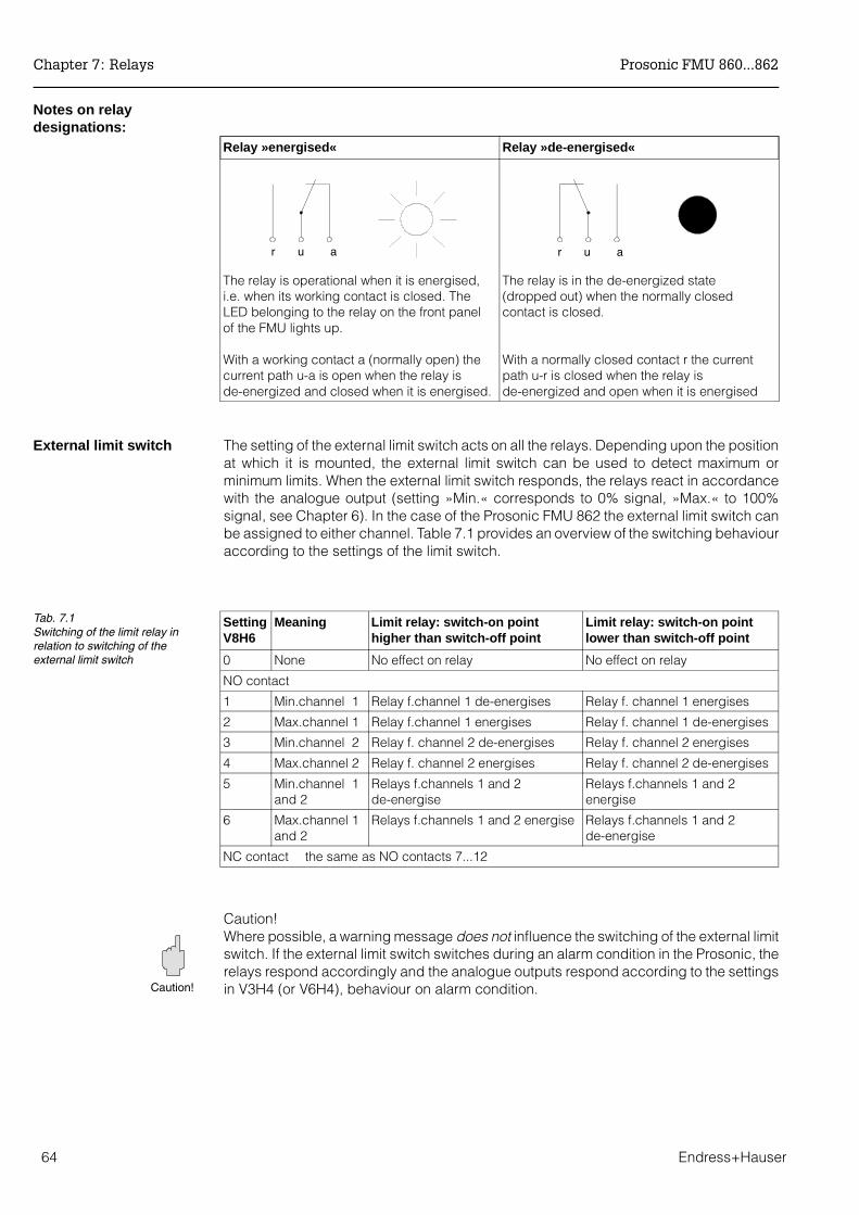
Notes on relaydesignations:
Relay »energised« Relay »de-energised«
The relay is operational when it is energised,i.e. when its working contact is closed. TheLED belonging to the relay on the front panelof the FMU lights up.
With a working contact a (normally open) thecurrent path u-a is open when the relay isde-energized and closed when it is energised.
The relay is in the de-energized state(dropped out) when the normally closedcontact is closed.
With a normally closed contact r the currentpath u-r is closed when the relay isde-energized and open when it is energised
External limit switch The setting of the external limit switch acts on all the relays. Depending upon the positionat which it is mounted, the external limit switch can be used to detect maximum orminimum limits. When the external limit switch responds, the relays react in accordancewith the analogue output (setting »Min.« corresponds to 0% signal, »Max.« to 100%signal, see Chapter 6). In the case of the Prosonic FMU 862 the external limit switch canbe assigned to either channel. Table 7.1 provides an overview of the switching behaviouraccording to the settings of the limit switch.
Caution!Where possible, a warning message does not influence the switching of the external limitswitch. If the external limit switch switches during an alarm condition in the Prosonic, therelays respond accordingly and the analogue outputs respond according to the settingsin V3H4 (or V6H4), behaviour on alarm condition.
r u a r u a
Setting V8H6
Meaning Limit relay: switch-on pointhigher than switch-off point
Limit relay: switch-on pointlower than switch-off point
0 None No effect on relay No effect on relay
NO contact
1 Min.channel 1 Relay f.channel 1 de-energises Relay f. channel 1 energises
2 Max.channel 1 Relay f.channel 1 energises Relay f. channel 1 de-energises
3 Min.channel 2 Relay f. channel 2 de-energises Relay f. channel 2 energises
4 Max.channel 2 Relay f. channel 2 energises Relay f. channel 2 de-energises
5 Min.channel 1and 2
Relays f.channels 1 and 2de-energise
Relays f.channels 1 and 2energise
6 Max.channel 1and 2
Relays f.channels 1 and 2 energise Relays f.channels 1 and 2de-energise
NC contact the same as NO contacts 7...12
Tab. 7.1Switching of the limit relay inrelation to switching of theexternal limit switch
Caution!
Chapter 7: Relays Prosonic FMU 860...862
64 Endress+Hauser
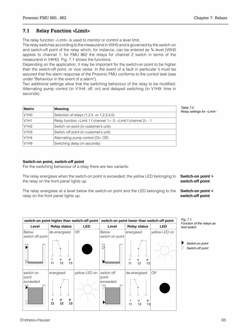
7.1 Relay Function »Limit«
The relay function »Limit« is used to monitor or control a level limit. The relay switches according to the measurand in V0H0 and is governed by the switch-onand switch-off point of the relay which, for instance, can be entered as % level (V0H0applies to channel 1; for FMU 862 the relays for channel 2 switch in terms of themeasurand in V4H0). Fig. 7.1 shows the functions. Depending on the application, it may be important for the switch-on point to be higherthan the switch-off point, or vice versa. In the event of a fault in particular it must beassured that the alarm response of the Prosonic FMU conforms to the control task (seeunder "Behaviour in the event of a alarm"). Two additional settings allow that the switching behaviour of the relay to be modified:Alternating pump control (in V1H4: off, on) and delayed switching (in V1H9: time inseconds).
Switch-on point, switch-off pointFor the switching behaviour of a relay there are two variants:
Switch-on point >switch-off point
The relay energises when the switch-on point is exceeded, the yellow LED belonging tothe relay on the front panel lights up.
Switch-on point <switch-off point
The relay energises at a level below the switch-on point and the LED belonging to therelay on the front panel lights up.
Matrix Meaning
V1H0 Selection of relays (1,2,5 or 1,2,3,4,5)
V1H1 Relay function »Limit 1 f.channel 1«: 0; »Limit f.channel 2« : 1
V1H2 Switch–on point (in customer’s unit)
V1H3 Switch–off point (in customer’s unit)
V1H4 Alternating pump control (On, Off)
V1H9 Switching delay (in seconds)
Table 7.2Relay settings for »Limit«
r u a11 12 13
r u a11 12 13
r u a11 12 13
r u a11 12 13
switch-on point higher than switch-off point switch-on point lower than switch-off point
Level Relay status LED Level Relay status LED
Below switch off point
de-energised Off Belowswitch on point
energised yellow LED on
switch onpointexceeded
energised yellow LED on switch offpointexceeded
de-energised Off
Fig. 7.1Function of the relays as limit switch
Switch-on point
Switch-off point
Prosonic FMU 860...862 Chapter 7: Relays
Endress+Hauser 65
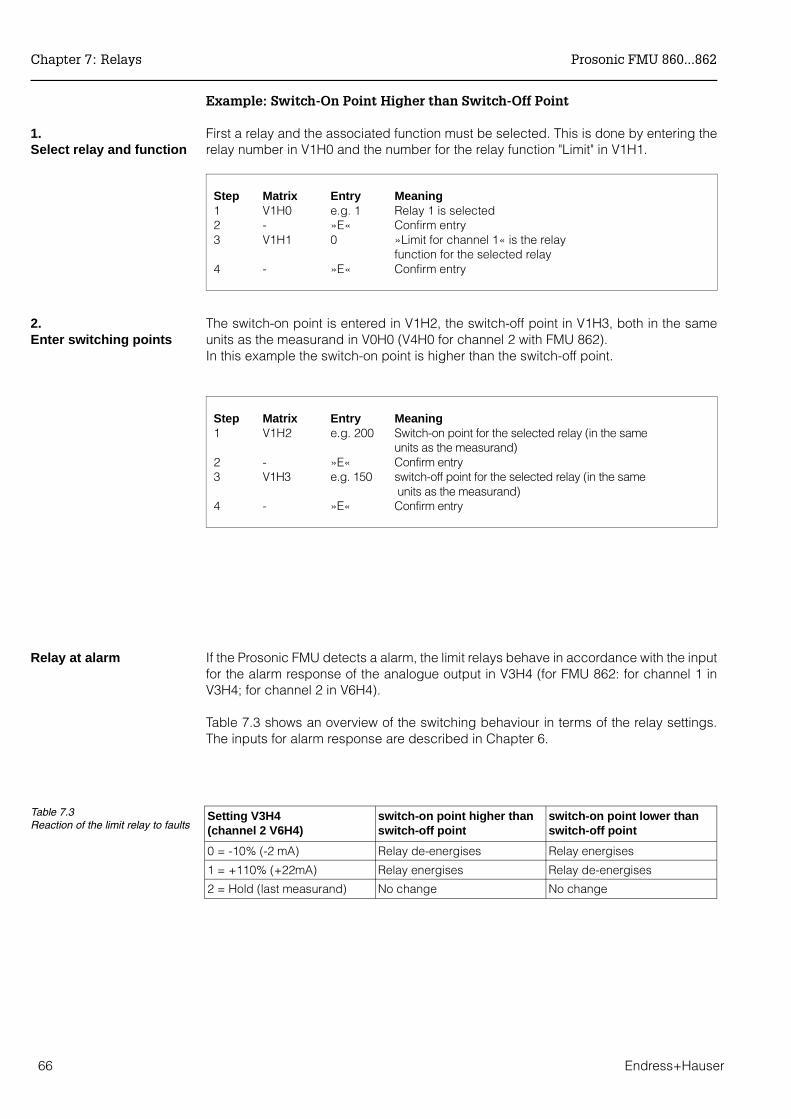
Example: Switch-On Point Higher than Switch-Off Point
1. Select relay and function
First a relay and the associated function must be selected. This is done by entering therelay number in V1H0 and the number for the relay function "Limit" in V1H1.
Step Matrix Entry Meaning 1 V1H0 e.g. 1 Relay 1 is selected2 - »E« Confirm entry3 V1H1 0 »Limit for channel 1« is the relay
function for the selected relay4 - »E« Confirm entry
2. Enter switching points
The switch-on point is entered in V1H2, the switch-off point in V1H3, both in the sameunits as the measurand in V0H0 (V4H0 for channel 2 with FMU 862).In this example the switch-on point is higher than the switch-off point.
Step Matrix Entry Meaning 1 V1H2 e.g. 200 Switch-on point for the selected relay (in the same
units as the measurand)2 - »E« Confirm entry 3 V1H3 e.g. 150 switch-off point for the selected relay (in the same
units as the measurand)4 - »E« Confirm entry
Relay at alarm If the Prosonic FMU detects a alarm, the limit relays behave in accordance with the inputfor the alarm response of the analogue output in V3H4 (for FMU 862: for channel 1 inV3H4; for channel 2 in V6H4).
Table 7.3 shows an overview of the switching behaviour in terms of the relay settings.The inputs for alarm response are described in Chapter 6.
Setting V3H4(channel 2 V6H4)
switch-on point higher thanswitch-off point
switch-on point lower thanswitch-off point
0 = -10% (-2 mA) Relay de-energises Relay energises
1 = +110% (+22mA) Relay energises Relay de-energises
2 = Hold (last measurand) No change No change
Table 7.3Reaction of the limit relay to faults
Chapter 7: Relays Prosonic FMU 860...862
66 Endress+Hauser

Typical ApplicationsThe size of the switching range, i.e. the difference between the switch-on and switch-offpoints, is defined in accordance with the control task.
• A relay operates as limit switch when the switching range is small or• A relay operates as two point-control when the switching range is large
(Fig.7.2).
Example: Limit switch If the relay is to operate as limit switch, the switching range is small, i.e. the switch-onand switch-off points are close together. The difference between the switch-on point andthe switch-off point should be at least 1%If the switch-on point is higher than the switch-off point the relay energises when theswitch-on point is exceeded. A level just below the switch-on point is then given asswitch-off point. When this level is reached, the relay de-energises at once.
Step Matrix Entry Meaning 1 V1H0 e.g. 2 Relay 2 is selected2 - »E« Confirm entry3 V1H1 0 Limit channel 1 is the relay function for the relay selected4 - »E« Confirm entry5 V1H2 e.g. 1 Switch-on point for selected relay
(in the same units as the measurand, e.g. 1 m) 6 - »E« Confirm entry7 V1H3 e.g. 0.95 switch-off point for the relay selected
(in the same units as the measurand e.g. 0.95 m)8 - »E« Confirm entry
Prosonic FMU 860...862 Chapter 7: Relays
Endress+Hauser 67
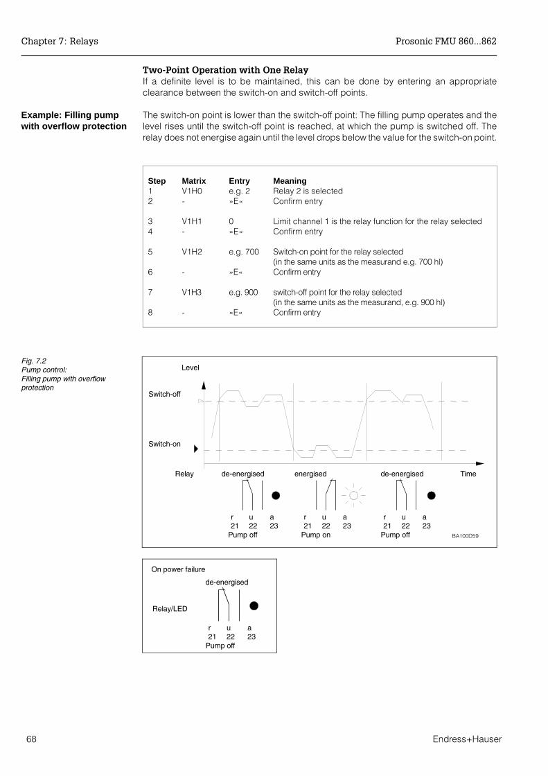
Two-Point Operation with One RelayIf a definite level is to be maintained, this can be done by entering an appropriateclearance between the switch-on and switch-off points.
Example: Filling pumpwith overflow protection
The switch-on point is lower than the switch-off point: The filling pump operates and thelevel rises until the switch-off point is reached, at which the pump is switched off. Therelay does not energise again until the level drops below the value for the switch-on point.
Step Matrix Entry Meaning1 V1H0 e.g. 2 Relay 2 is selected2 - »E« Confirm entry
3 V1H1 0 Limit channel 1 is the relay function for the relay selected4 - »E« Confirm entry
5 V1H2 e.g. 700 Switch-on point for the relay selected(in the same units as the measurand e.g. 700 hl)
6 - »E« Confirm entry
7 V1H3 e.g. 900 switch-off point for the relay selected(in the same units as the measurand, e.g. 900 hl)
8 - »E« Confirm entry
Level
de-energised energised de-energisedRelay Time
BA100D59
Switch-off
Switch-on
r u a21 22 23
Pump off
r u a21 22 23
Pump on
r u a21 22 23
Pump off
Fig. 7.2Pump control:Filling pump with overflowprotection
r u a21 22 23
Pump off
On power failure
de-energised
Relay/LED
Chapter 7: Relays Prosonic FMU 860...862
68 Endress+Hauser
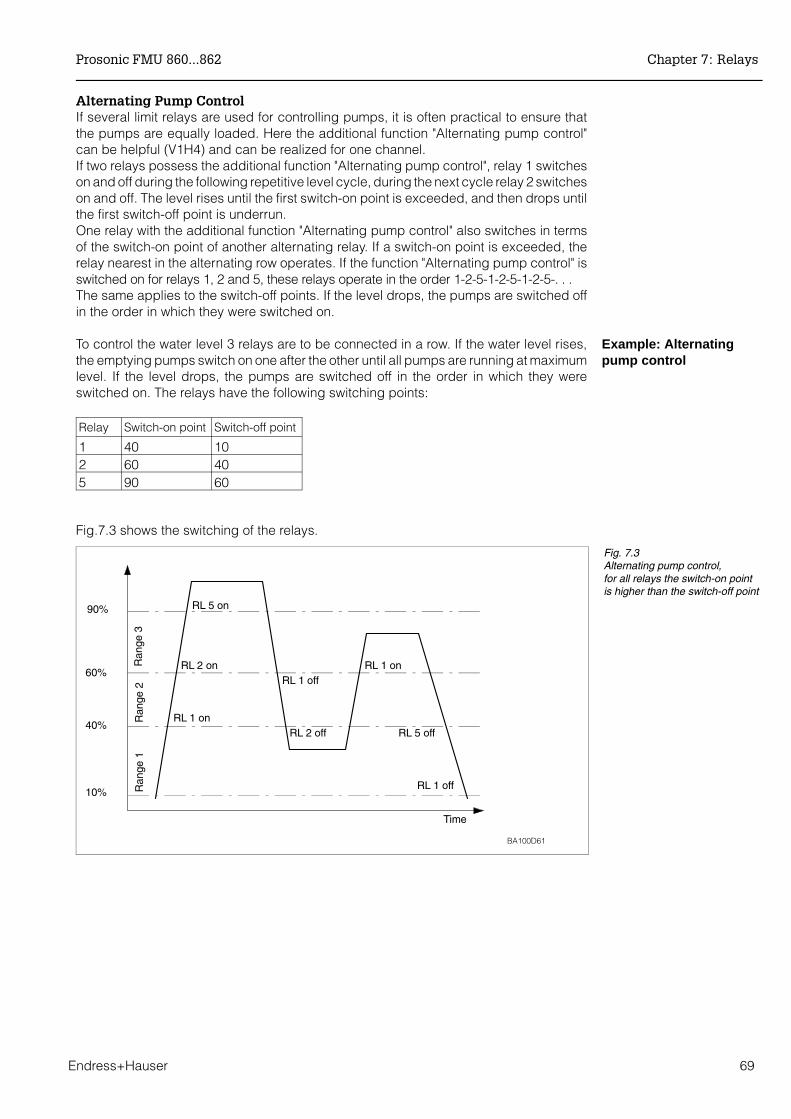
Alternating Pump ControlIf several limit relays are used for controlling pumps, it is often practical to ensure thatthe pumps are equally loaded. Here the additional function "Alternating pump control"can be helpful (V1H4) and can be realized for one channel.If two relays possess the additional function "Alternating pump control", relay 1 switcheson and off during the following repetitive level cycle, during the next cycle relay 2 switcheson and off. The level rises until the first switch-on point is exceeded, and then drops untilthe first switch-off point is underrun.One relay with the additional function "Alternating pump control" also switches in termsof the switch-on point of another alternating relay. If a switch-on point is exceeded, therelay nearest in the alternating row operates. If the function "Alternating pump control" isswitched on for relays 1, 2 and 5, these relays operate in the order 1-2-5-1-2-5-1-2-5-. . .The same applies to the switch-off points. If the level drops, the pumps are switched offin the order in which they were switched on.
Example: Alternatingpump control
To control the water level 3 relays are to be connected in a row. If the water level rises,the emptying pumps switch on one after the other until all pumps are running at maximumlevel. If the level drops, the pumps are switched off in the order in which they wereswitched on. The relays have the following switching points:
Relay Switch-on point Switch-off point
1 40 102 60 405 90 60
Fig.7.3 shows the switching of the relays.
90%
60%
40%
10%
RL 1 on
RL 2 on
RL 5 on
Time
RL 1 off
RL 2 off
RL 1 on
RL 5 off
RL 1 off
BA100D61
Ran
ge 1
Ran
ge 2
Ran
ge 3
Fig. 7.3Alternating pump control,for all relays the switch-on pointis higher than the switch-off point
Prosonic FMU 860...862 Chapter 7: Relays
Endress+Hauser 69
Step Matrix Entry Meaning
1 V1H0 1 »E« Relay 1 was selected 2 V1H1 0 »E« Relay function for relay 1 is limit in channel 13 V1H2 40 »E« Switch-on point 1 is say 40% (when % is the customer’s unit)4 V1H3 10 »E« switch-off point is say 10% (when % is the customer’s unit)5 V1H4 1 »E« Relay 1 was provided with additional function
»Alternating pump control«
6 V1H0 2 »E« Relay 2 was selected7 V1H1 0 »E« Relay function for relay 2 is limit in channel 18 V1H2 60 »E« Switch-on point 1 is say 60% (when % is the customer’s unit)9 V1H3 40 »E« switch-off point 1 is say 40% (when % is the customer’s unit)10 V1H4 1 »E« Relay 2 was provided with additional function
»Alternating pump control«
11 V1H0 3 »E« Relay 3 was selected 12 V1H1 0 »E« Relay function for relay 3 is limit in channel 113 V1H2 90 »E« Switch-on point 1 is say 90% (when % is the customer’s unit)14 V1H3 60 »E« switch-off point 1 is say 60% (when% is the customer’s unit)15 V1H4 1 »E« Relay 3 was provided with the additional function
»Alternating pump control«
16 V1H9 10 »E« Switching delay of 10 seconds for all relays.
Note!• "Alternating pump control" can, of course, only be effective when two or more limit
relays in the same channel possess this function. • The ranges with the switch-on and switch-off points may overlap, e.g. range 1
switch-on at 80%, switch-off at 30%, range 2 switch-on at 60%, switch-off and 20%. Where two pumps in the same range are to operate alternately, their switch-on andswitch-off points are identical. This switching response can be achieved byassigning switch points to the second relay which can never be reached.Example: in the switching range between 60% and 40%, two pumps should beoperated alternately, i.e. when pump 1 is running, pump 2 is switched off and viceversa. The relays are programmed as follows:Relay 1 Switch-on point 60%, switch-off point 40%;Relay 2 Switch-on point e.g. 160%, switch-off point e.g. 120%.
• If all the relays are employed for pump control, alarms denoted by the 0/4…20 mAsignal may be registered as –10 or +110 % signals. The installation of a separatemeans of protection against overflow or running dry is then recommended.
• With "Alternating pump control" a switching delay of 0...100 s can be set in V1H9(default = 1 s).
Note!
Chapter 7: Relays Prosonic FMU 860...862
70 Endress+Hauser
Switching delayTo prevent the load becoming too heavy when two or more connected units (e.g. pumps)are switched simultaneously, a switching delay can be set. This delay then applies to allrelays with the function "Alternating pump control" (with FMU 862 for channel 1 andchannel 2).
FunctionIf two relays ought to operate at the same level, the relay with the lower number operatesat once, followed after a delay by the one with the higher number, i.e. the delay enteredin V1H9 (default = 1 s).If even a third relay ought to operate at the same level, the relay with the highest numberis delayed by twice the time entered in V1H9.
Step Matrix Entry Meaning1 V1H9 e.g. 10 10 s is the minimum interval
between operation of two relays 2 - »E« Confirm entry
7.2 Relay Function »Alarm Relay«
The function of the alarm relay is to signal disturbances, e.g. with the aid of externalwarning lamps, horns or other connected devices. The relay is switched in accordance with the behaviour of the Prosonic FMU in the eventof a alarm. The response in the absence of an echo can be set separately.A comprehensive description of the behaviour can be found in Chapter 9. Supplementarysettings to the switching behaviour of the relay are not necessary.• The LED of an alarm indicating relay is alight when operation is free from fault,
during which time the relay is energized.• The fifth relay is preset for the function »Alarm relay«. The associated LED lights up
when operation is free from fault. Any other relay function can be assigned to thefifth relay.
• For external indication of alarms warning or indicator lamps must be connected tothe normally closed contact of the alarm relay.
Step Matrix Entry Meaning 1 V1H0 e.g. 2 Relay 2 is selected2 - »E« Confirm entry3 V1H1 8 Alarm relay is the function of the selected relay4 - »E« Confirm entry
Prosonic FMU 860...862 Chapter 7: Relays
Endress+Hauser 71

7.3 Relay Function »Tendency«
The function of the tendency relay is to monitor or control the periodic differences inflowrate or level. The tendency is +1% if the measurand in V0H0 increases by 1% of themaximum flowrate or the maximum of the level within one minute. The tendency is –1%if the measurand in V0H0 drops by 1% of the maximum flowrate or level within one minute.The maximum flowrate is set by the chosen or entered Q/h curve. The maximum level isthe linearised end value or the 100% level. Switching of the relay is done together withthe switch-on point and switch-off point of the tendency.
Switch-on point greaterthan switch-off point
Switch-on point smallerthan switch-off point
The relay energizes when the tendency exceeds the switch-on point and de-energizeswhen the tendency drops below the switch-off point.
The relay energizes when the tendency drops below the switch-on point andde-energizes when it exceeds the switch-off point.
Step Matrix Entry Meaning1 V1H0 e.g.. 2 Relay 2 is selected2 - »E« Confirm entry3 V1H1 2 »Tendency channel 1« is the function of the selected relay 4 - »E« Confirm entry5 V1H2 e.g. 2 Enter switch-on point at 2% increase/min of measurand6 - »E« Confirm entry7 V1H3 e.g. 0.5 Enter switch-off point at 0.5% increase/min8 - »E« Confirm entry
Tendency relay on alarm If the Prosonic FMU identifies an alarm, then the tendency relay maintains its switchingstatus.
Chapter 7: Relays Prosonic FMU 860...862
72 Endress+Hauser
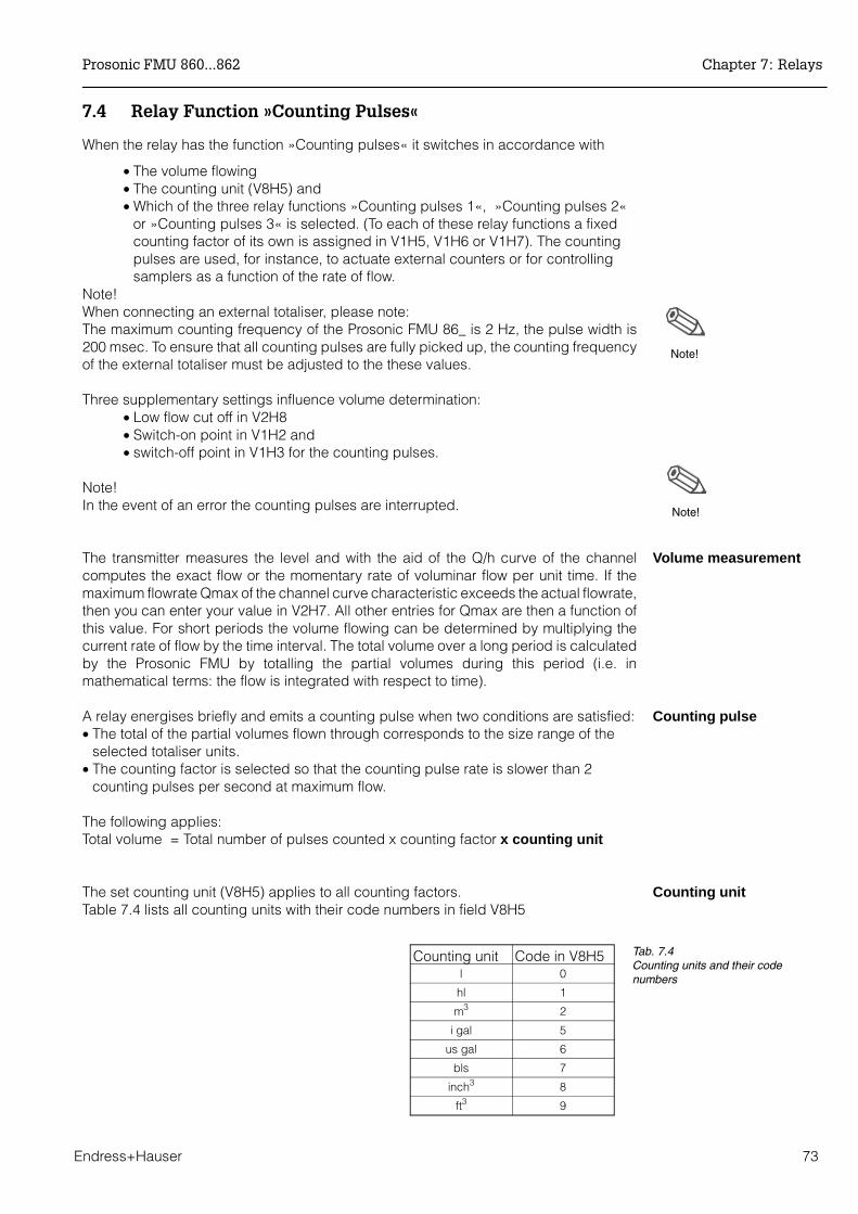
7.4 Relay Function »Counting Pulses«
When the relay has the function »Counting pulses« it switches in accordance with
• The volume flowing• The counting unit (V8H5) and • Which of the three relay functions »Counting pulses 1«, »Counting pulses 2«
or »Counting pulses 3« is selected. (To each of these relay functions a fixedcounting factor of its own is assigned in V1H5, V1H6 or V1H7). The countingpulses are used, for instance, to actuate external counters or for controllingsamplers as a function of the rate of flow.
Note!When connecting an external totaliser, please note:The maximum counting frequency of the Prosonic FMU 86_ is 2 Hz, the pulse width is200 msec. To ensure that all counting pulses are fully picked up, the counting frequencyof the external totaliser must be adjusted to the these values.
Three supplementary settings influence volume determination: • Low flow cut off in V2H8• Switch-on point in V1H2 and • switch-off point in V1H3 for the counting pulses.
Note!In the event of an error the counting pulses are interrupted.
Volume measurementThe transmitter measures the level and with the aid of the Q/h curve of the channelcomputes the exact flow or the momentary rate of voluminar flow per unit time. If themaximum flowrate Qmax of the channel curve characteristic exceeds the actual flowrate,then you can enter your value in V2H7. All other entries for Qmax are then a function ofthis value. For short periods the volume flowing can be determined by multiplying thecurrent rate of flow by the time interval. The total volume over a long period is calculatedby the Prosonic FMU by totalling the partial volumes during this period (i.e. inmathematical terms: the flow is integrated with respect to time).
Counting pulseA relay energises briefly and emits a counting pulse when two conditions are satisfied:• The total of the partial volumes flown through corresponds to the size range of the
selected totaliser units.• The counting factor is selected so that the counting pulse rate is slower than 2
counting pulses per second at maximum flow.
The following applies:Total volume = Total number of pulses counted x counting factor x counting unit
Counting unitThe set counting unit (V8H5) applies to all counting factors.Table 7.4 lists all counting units with their code numbers in field V8H5
Note!
Note!
Counting unit Code in V8H5l 0
hl 1
m3 2
i gal 5
us gal 6
bls 7
inch3 8
ft3 9
Tab. 7.4Counting units and their codenumbers
Prosonic FMU 860...862 Chapter 7: Relays
Endress+Hauser 73

Counting factors The counting pulse rate of a relay depends on the assigned counting factor. There is achoice of three counting factors:
Any counting factor can be entered in the matrix field V1H5, V1H6 and V1H7corresponding to the counting mode. If a maximum value of 19999 is exceeded (e.g.after selecting a new Q/h curve), or the counting pulse rate is larger than 2 pulses persecond with maximum flowrate, then the Prosonic counting factors are automaticallyadjusted. A warning message E 620 is displayed and the counting factors in V1H5 andV1H6 and V1H7 can be calculated and confirmed. If no correction using the selectedcounting units is possible, then the warning message E 621 is displayed. Other technicalunits are then to be entered in V8H5.
Step Matrix Entry Meaning Select counting unit1 V8H5 2 m3 was selected as counting unit2 - »E« Confirm entry
Select the relay and select one of the relay functions »Counting pulses«3 V1H0 1 Relay 1 is selected 4 - »E« Confirm entry5 V1H1 5 Counting pulses 2 is the function for relay 1
(in V1H6 »counting factor 2)6 - »E« Confirm entry7 V1H0 2 Relay 2 is selected8 - »E« Confirm entry9 V1H1 4 Counting pulses 1 is the function for relay 2
(in V1H5 counting factor 1)10 - »E« Confirm entry 11 V1H5 1000 Counting factor 1 is selected and 1000 is entered
for 1000 m3
12 - »E« Confirm entry
Countingfactor 1
In V1H5 and applies to relayfunction »counting pulses 1
If a totalizer is installed in the FMU, thecounting factor 1 always applies to this unit too.
Countingfactor 2
In V1H6 and applies to relaisfunction »counting pulses 2«
With this counting factor the software totalizerin Prosonic FMU always counts
Countingfactor 3
In V1H7 applies to relaisfunction »counting pulses 3«
The counting factor applies solely to externalflow measuring units
Tab. 7.5Selecting the counting factors
Chapter 7: Relays Prosonic FMU 860...862
74 Endress+Hauser
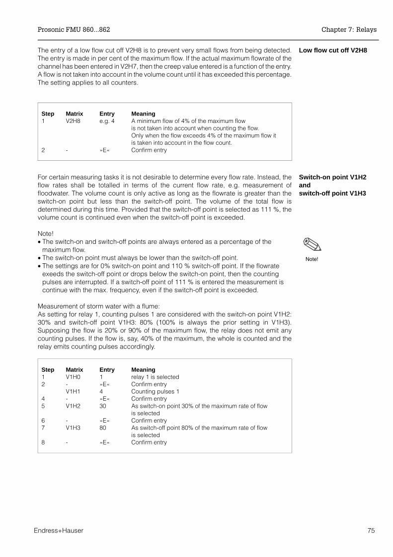
Low flow cut off V2H8 The entry of a low flow cut off V2H8 is to prevent very small flows from being detected.The entry is made in per cent of the maximum flow. If the actual maximum flowrate of thechannel has been entered in V2H7, then the creep value entered is a function of the entry.A flow is not taken into account in the volume count until it has exceeded this percentage.The setting applies to all counters.
Step Matrix Entry Meaning 1 V2H8 e.g. 4 A minimum flow of 4% of the maximum flow
is not taken into account when counting the flow.Only when the flow exceeds 4% of the maximum flow it is taken into account in the flow count.
2 - »E« Confirm entry
Switch-on point V1H2and switch-off point V1H3
For certain measuring tasks it is not desirable to determine every flow rate. Instead, theflow rates shall be totalled in terms of the current flow rate, e.g. measurement offloodwater. The volume count is only active as long as the flowrate is greater than theswitch-on point but less than the switch-off point. The volume of the total flow isdetermined during this time. Provided that the switch-off point is selected as 111 %, thevolume count is continued even when the switch-off point is exceeded.
Note!• The switch-on and switch-off points are always entered as a percentage of the
maximum flow.• The switch-on point must always be lower than the switch-off point.• The settings are for 0% switch-on point and 110 % switch-off point. If the flowrate
exeeds the switch-off point or drops below the switch-on point, then the countingpulses are interrupted. If a switch-off point of 111 % is entered the measurement iscontinue with the max. frequency, even if the switch-off point is exceeded.
Measurement of storm water with a flume:As setting for relay 1, counting pulses 1 are considered with the switch-on point V1H2:30% and switch-off point V1H3: 80% (100% is always the prior setting in V1H3).Supposing the flow is 20% or 90% of the maximum flow, the relay does not emit anycounting pulses. If the flow is, say, 40% of the maximum, the whole is counted and therelay emits counting pulses accordingly.
Step Matrix Entry Meaning 1 V1H0 1 relay 1 is selected2 - »E« Confirm entry
V1H1 4 Counting pulses 14 - »E« Confirm entry 5 V1H2 30 As switch-on point 30% of the maximum rate of flow
is selected6 - »E« Confirm entry7 V1H3 80 As switch-off point 80% of the maximum rate of flow
is selected8 - »E« Confirm entry
Note!
Prosonic FMU 860...862 Chapter 7: Relays
Endress+Hauser 75

7.5 Relay Function »Timing Pulses«
The relay function »Timing pulses« can be used for controlling a sampler with respectto time, or for cleaning a screen at definite intervals of time.
• The relay switches when the time set in V1H8 in minutes expires.• The shortest time is 1 min, the longest 1500 min. • After the set time of the timing pulses has elapsed the relay energises briefly,
the LED on the front panel of the Prosonic FMU flashes once. Thus anexternally connected relay can be actuated to control a sampler or screenmotor.
Caution!During a fault the timing pulses continue to be counted – if possible.
Step Matrix Entry Meaning 1 V1H0 e.g.4 Relay 4 is selected2 - »E« Confirm entry3 V1H1 7 Timing pulse is the function of the relay selected4 - »E« Confirm entry5 V1H8 60 The selected relay energises once every 60 minutes6 - »E« Confirm entry
7.6 Relay Function »Back Water Alarm«
The ”back pressure” relay function indicates disturbances and back pressure in thechannels and weirs, e.g. using the external warning lamps, horns or other downstreamunits. Switching on such a unit depends on the ratio h2 (height downstream of the weir)to h1 (height upstream of the weir) which is entered in V5H8. The relay is activated whenthe ratio is exceeded.
Step Matrix Entry Meaning1 V1H0 e.g. 4 Relay selected for alarm relay2 - ”E” Confirm entry3 V1H1 9 ”Back water alarm” is relay function for Relay 14 - ”E” Confirm entry
Caution!
Chapter 7: Relays Prosonic FMU 860...862
76 Endress+Hauser
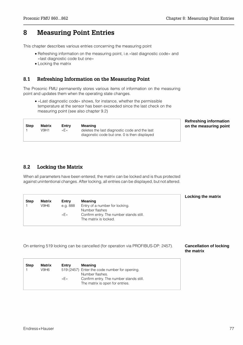
8 Measuring Point Entries
This chapter describes various entries concerning the measuring point
• Refreshing information on the measuring point, i.e.»last diagnostic code« and»last diagnostic code but one«
• Locking the matrix
8.1 Refreshing Information on the Measuring Point
The Prosonic FMU permanently stores various items of information on the measuringpoint and updates them when the operating state changes.
• »Last diagnostic code« shows, for instance, whether the permissibletemperature at the sensor has been exceeded since the last check on themeasuring point (see also chapter 9.2)
Refreshing informationon the measuring point Step Matrix Entry Meaning
1 V9H1 »E« deletes the last diagnostic code and the last diagonstic code but one. 0 is then displayed
8.2 Locking the Matrix
When all parameters have been entered, the matrix can be locked and is thus protectedagainst unintentional changes. After locking, all entries can be displayed, but not altered.
Locking the matrixStep Matrix Entry Meaning 1 V9H6 e.g. 888 Entry of a number for locking.
Number flashes»E« Confirm entry. The number stands still.
The matrix is locked.
Cancellation of lockingthe matrix
On entering 519 locking can be cancelled (for operation via PROFIBUS-DP: 2457).
Step Matrix Entry Meaning 1 V9H6 519 (2457) Enter the code number for opening.
Number flashes.»E« Confirm entry. The number stands still.
The matrix is open for entries.
Prosonic FMU 860...862 Chapter 8: Measuring Point Entries
Endress+Hauser 77

Chapter 8: Measuring Point Entries Prosonic FMU 860...862
78 Endress+Hauser
9 Diagnosis and Trouble-Shooting
This section contains the following:
• Two types of faults: alarms and warnings• Fault analysis and trouble-shooting tables• Suppression of interference signals in unfavorable installation conditions• Simulation mode for testing other units connected• Instructions for replacing the transmitter or sensor• Instructions on repairs
9.1 Two Types of Fault: Alarms and Warnings
The transmitter continuously monitors the operational function of the measuring line. If itrecognises a fault, then it responds with the following:
• the LED on the front panel flashes• symbols are shown on the display • an error code is given in field V9H0 and • the analogue outputs assume their preprogrammed values and• connected units are deactivated by the programmed relay.
With serious faults, the status is shown as an alarm. All other faults are indicated aswarnings (e.g. simple operating error).No further measurement are made with a fault indication. Further measurements arealways attempted with a warning but measuring errors cannot be ruled out.
AlarmAlarmIf the Prosonic FMU detects an alarm, i.e. a functional fault by which no furthermeasurement is possible, then the following takes place:
• All yellow LEDs flash.• The »alarm« relay de-activates.• The symbol for status message appears on the display
(see section 7).• The analogue signal reverts to the status selected
(either –10% or +110% of the current span or the last measured value (hold),see section 6).
• The »limit value« relays react according to the size of the analogue signal(see section 7).If other relay functions are available then these also apply:- The »tendency« relay maintain their switching position (see section 7).- »Count pulse« relays de-energise. As long as the fault remains, then no
counting pulses are sent.- »Interval timer« relays remain unaffected and switch
– if the function allows – after a given time for the time pulse.• The diagnostic message on the source of the fault is shown in filed V9H0.
Explanation of error codes is given in table 9.1.
Prosonic FMU 860...862 Chapter 9: Diagnosis and Trouble-Shooting
Endress+Hauser 79
Warning WarningIf the Prosonic FMU detects a simple operating error or a fault which still allowsmeasurement to be carried out, then it activates a warning. As long as the warningremains, then the measuring signal may be subject to significant measuring errors givingrise to the following responses:
• The green LED flashes. • The »alarm« relay remains energised with all other relays remaining
unaffected.• The symbol for status indication flashes on the display. • The poutput signal can – e.g. together with input errors – be subject to
significant measurement errors.• The diagnostic message on the source of the fault is shown in field V9H0.
Explanation of error codes is given in Table 9.1.
Selectable warningswhen no echo is detected
Special Case: Trouble-Shooting on Lost Echo
In two special measuring situations – when the signal/noise ratio is too small or the echoattenuation is too large – the response of the alarm relay can be set.
The fault handling of a non-existent echo is selected by entering a number in field V3H3(Field V6H3 with a two-channel unit).
• 0 = »Warning« (default value), the last measured value is retained.• 1 = »Alarm«.
A non-existent echo is to be treated as an alarm
Step Matrix Entry Meaning Channel 21 V3H3 1 If no echo is present, the Prosonic FMU V6H3 should carry out all responses to an alarm.2 - »E« Register entry
Chapter 9: Diagnosis and Trouble-Shooting Prosonic FMU 860...862
80 Endress+Hauser
9.2 Fault Analysis
For analysing faults it is important to know,
• what fault has occured• whether other faults have occured• whtether a short-term fault has occurred but which no longer exists (e.g. too
high temperature at the sensor for a brief period of time) and also• which fault was last corrected.
Because:• There are faults which are corrected immediately and others which can only
be corrected by Endress+Hauser Service engineers.• A fault can have more than one source at the same time.• Correcting one fault can cause a new and additional fault to occur.
Fault indicationsProsonic FMU
The Prosonic FMU provides you with the following information to carry out fault analysis.
• To indicate the source of the fault, the »most important« fault is shown in fieldV9H0.A fault is assigned a priority in the factory, i.e. if a fault of low priority existsand then one with a higher priority occurs, then the fault with the higherpriority will be displayed in field V9H0 (see Table 9.1).Pressing the »+« key shows other faults which may be present.
• The previously corrected fault is shown in field V9H1. Pressing the »E« keyclears this display (the last but one fault code is also cleared, for applicationssee below).
• The last but one fault is shown in field V9H2. Pressing the »E« key clears thisdisplay (the previously corrected fault is also cleared).
Example of using »previous fault« V9H1Was the transmitter or sensor always fully operational? For example: was the sensortemperature always within the permissible range? The error code E661 is shown in V9H1,if the temperature range was exceeded. If the Prosonic FMU was correctly set inoperation (instrument reset with commissioning and the display in V9H1 cleared, seeSection 8) and was always fully operational, then no fault code should appear in the field»last but one fault«.If no fault is shown in field V9H1, then the ultrasonic sensor and the transmitter werealways fully operational from that point since the last reset.
Prosonic FMU 860...862 Chapter 9: Diagnosis and Trouble-Shooting
Endress+Hauser 81
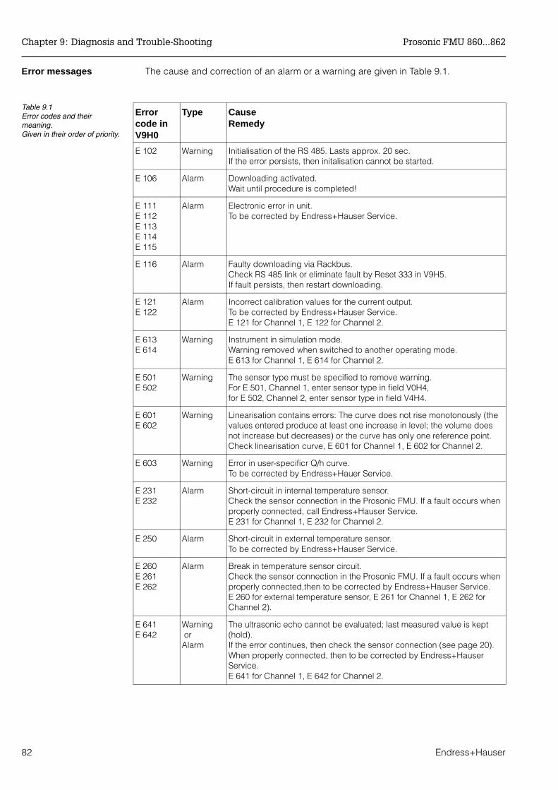
Error messages The cause and correction of an alarm or a warning are given in Table 9.1.
Errorcode inV9H0
Type Cause Remedy
E 102 Warning Initialisation of the RS 485. Lasts approx. 20 sec.If the error persists, then initalisation cannot be started.
E 106 Alarm Downloading activated.Wait until procedure is completed!
E 111E 112E 113E 114E 115
Alarm Electronic error in unit.To be corrected by Endress+Hauser Service.
E 116 Alarm Faulty downloading via Rackbus.Check RS 485 link or eliminate fault by Reset 333 in V9H5.If fault persists, then restart downloading.
E 121E 122
Alarm Incorrect calibration values for the current output.To be corrected by Endress+Hauser Service.E 121 for Channel 1, E 122 for Channel 2.
E 613E 614
Warning Instrument in simulation mode. Warning removed when switched to another operating mode.E 613 for Channel 1, E 614 for Channel 2.
E 501E 502
Warning The sensor type must be specified to remove warning.For E 501, Channel 1, enter sensor type in field V0H4,for E 502, Channel 2, enter sensor type in field V4H4.
E 601E 602
Warning Linearisation contains errors: The curve does not rise monotonously (thevalues entered produce at least one increase in level; the volume doesnot increase but decreases) or the curve has only one reference point.Check linearisation curve, E 601 for Channel 1, E 602 for Channel 2.
E 603 Warning Error in user-specificr Q/h curve.To be corrected by Endress+Hauer Service.
E 231E 232
Alarm Short-circuit in internal temperature sensor. Check the sensor connection in the Prosonic FMU. If a fault occurs whenproperly connected, call Endress+Hauser Service.E 231 for Channel 1, E 232 for Channel 2.
E 250 Alarm Short-circuit in external temperature sensor. To be corrected by Endress+Hauser Service.
E 260E 261E 262
Alarm Break in temperature sensor circuit.Check the sensor connection in the Prosonic FMU. If a fault occurs whenproperly connected,then to be corrected by Endress+Hauser Service. E 260 for external temperature sensor, E 261 for Channel 1, E 262 forChannel 2).
E 641E 642
Warning orAlarm
The ultrasonic echo cannot be evaluated; last measured value is kept(hold).If the error continues, then check the sensor connection (see page 20).When properly connected, then to be corrected by Endress+HauserService.E 641 for Channel 1, E 642 for Channel 2.
Table 9.1Error codes and theirmeaning.Given in their order of priority.
Chapter 9: Diagnosis and Trouble-Shooting Prosonic FMU 860...862
82 Endress+Hauser

Error diagnosisTable 9.2 gives instructions on error diagnosis with a transmitter fully operational.
Fault Cause and Remedy
Measured value is incorrect Check the distance between sensor membrane andproduct surface shown in V0H8– if the distance is correctly shown, then check the full
and empty calibration in V0H1 and V0H2– if linearisation has been carried out, then check
linearisation parameters.The same for Channel 2 in V4H8, V4H1, V4H2
Measured value indicates"full" whenempty orremains constant as level rises
Interference echoes: The sensor is measuring e.g. anedge of mounting pipe.Retarget the sensor.Select fixed target suppression (see Section 9.3).
Measured value indicates less thanfull when full.Measured value changes whenproduct level constant
Multiple echoes– check whether the blocking distance is correct or– retarget the sensor or– select another level application in field V0H3The same for Channel 2 in field V4H3
The measured value remainsconstant when the level drops belowa specific value
Interference echos– retarget the sensor – fixed target suppression (see Section 9.3)
Sporadic measurement error withturbulent surface of liquid, e.g.agitators
No echo or else temporary spurious echo occurs– increase factor for envelope curve statistics,
see Section 9.3 – increase integration time for analogue signal,
see Section 6.1
Relay does not switch correctly Incorrect settings, e.g. in incorrect units – check relay settings – simulate settings in simulation mode for level,
see Section 9.4
Table 9.2Trouble-shooting table for a fullyoperating transmitter
E 643 Warning Difference between Channel 1 and Channel 2 too large or negative.
E 661E 662
Warning Temperature at sensor too high. Check the measuring point.(Temperature compensation calculated for 80 °C).E 661 for Channel 1, E 662 for Channel 2.
E 620 Warning Counting factor too small and has been automatically adjusted. Pleaseconfirm this adjustment: Go to the matrix fields V1H5, V1H6, V1H7 forcounter factors and press »E« (see Chapter 7).
E 621 Warning Counter factor too small and cannot be corrected in the selected units.Please enter other units in V8H5.
Prosonic FMU 860...862 Chapter 9: Diagnosis and Trouble-Shooting
Endress+Hauser 83
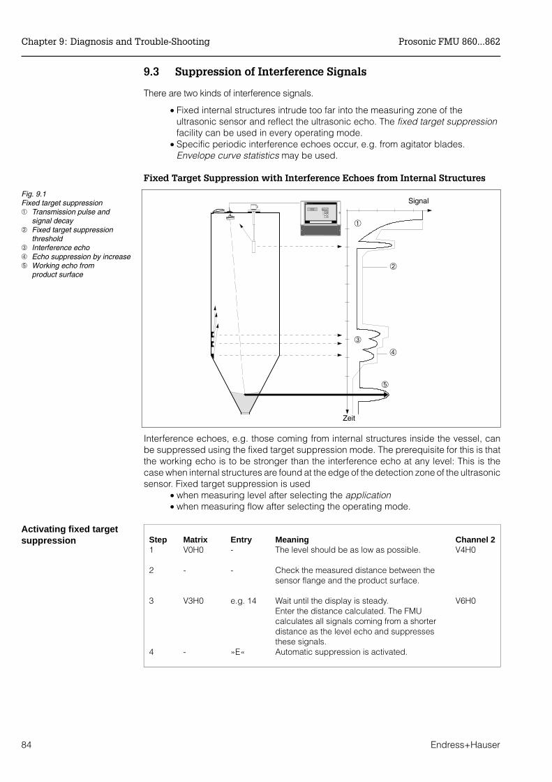
9.3 Suppression of Interference Signals
There are two kinds of interference signals.
• Fixed internal structures intrude too far into the measuring zone of theultrasonic sensor and reflect the ultrasonic echo. The fixed target suppressionfacility can be used in every operating mode.
• Specific periodic interference echoes occur, e.g. from agitator blades.Envelope curve statistics may be used.
Fixed Target Suppression with Interference Echoes from Internal Structures
Interference echoes, e.g. those coming from internal structures inside the vessel, canbe suppressed using the fixed target suppression mode. The prerequisite for this is thatthe working echo is to be stronger than the interference echo at any level: This is thecase when internal structures are found at the edge of the detection zone of the ultrasonicsensor. Fixed target suppression is used
• when measuring level after selecting the application • when measuring flow after selecting the operating mode.
Activating fixed targetsuppression Step Matrix Entry Meaning Channel 2
1 V0H0 - The level should be as low as possible. V4H0
2 - - Check the measured distance between thesensor flange and the product surface.
3 V3H0 e.g. 14 Wait until the display is steady. V6H0Enter the distance calculated. The FMUcalculates all signals coming from a shorterdistance as the level echo and suppressesthese signals.
4 - »E« Automatic suppression is activated.
Signal
➀
➁
➂
➃
➄
Zeit
Fig. 9.1Fixed target suppression➀ Transmission pulse and
signal decay➁ Fixed target suppression
threshold➂ Interference echo➃ Echo suppression by increase➄ Working echo from
product surface
Chapter 9: Diagnosis and Trouble-Shooting Prosonic FMU 860...862
84 Endress+Hauser
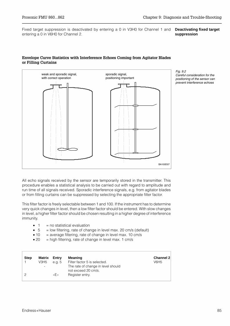
Deactivating fixed targetsuppression
Fixed target suppression is deactivated by entering a 0 in V3H0 for Channel 1 andentering a 0 in V6H0 for Channel 2.
Envelope Curve Statistics with Interference Echoes Coming from Agitator Bladesor Filling Curtains
All echo signals received by the sensor are temporarily stored in the transmitter. Thisprocedure enables a statistical analysis to be carried out with regard to amplitude andrun time of all signals received. Sporadic interference signals, e.g. from agitator bladesor from filling curtains can be suppressed by selecting the appropriate filter factor.
This filter factor is freely selectable between 1 and 100. If the instrument has to determinevery quick changes in level, then a low filter factor should be entered. With slow changesin level, a higher filter factor should be chosen resulting in a higher degree of interferenceimmunity.
• 1 = no statistical evaluation• 5 = low filtering, rate of change in level max. 20 cm/s (default) • 10 = average filtering, rate of change in level max. 10 cm/s • 20 = high filtering, rate of change in level max. 1 cm/s
Step Matrix Entry Meaning Channel 21 V3H5 e.g. 5 Filter factor 5 is selected. V6H5
- The rate of change in level should not exceed 20 cm/s.
2 »E« Register entry.
BA100D07
sporadic signal,positioning important
weak and sporadic signal,with correct operation
Fig. 9.2Careful consideration for thepositioning of the sensor canprevent interference echoes
Prosonic FMU 860...862 Chapter 9: Diagnosis and Trouble-Shooting
Endress+Hauser 85
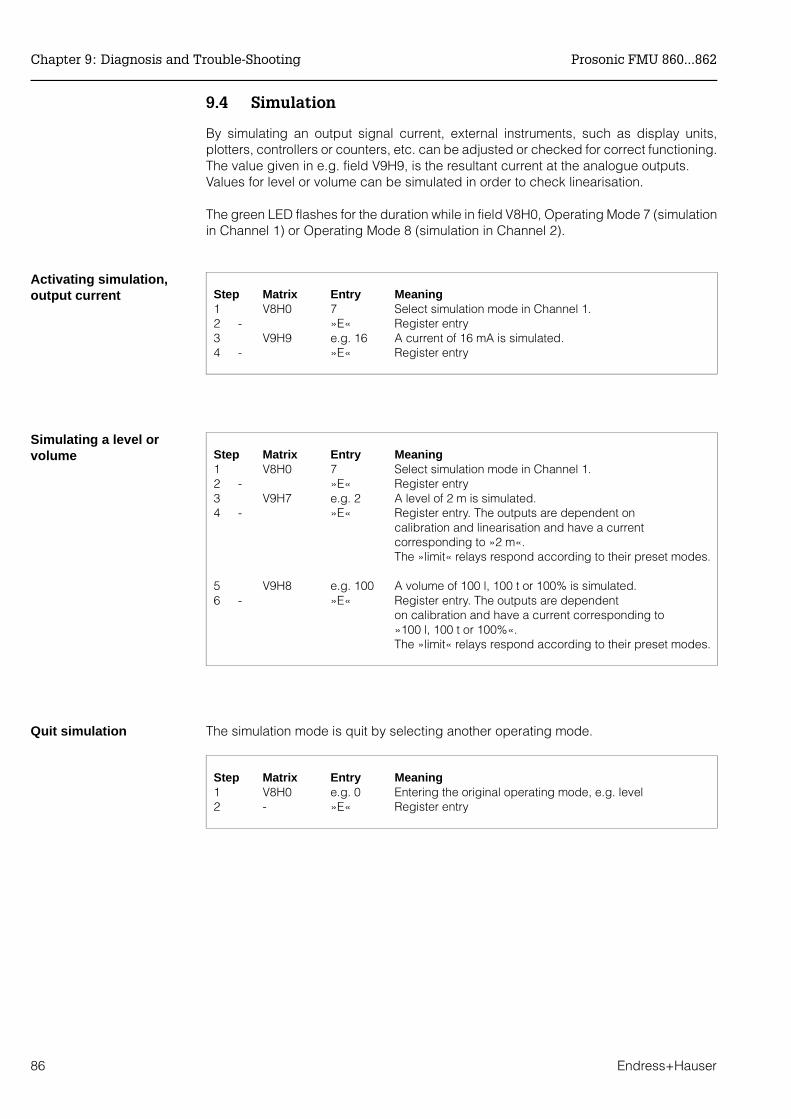
9.4 Simulation
By simulating an output signal current, external instruments, such as display units,plotters, controllers or counters, etc. can be adjusted or checked for correct functioning.The value given in e.g. field V9H9, is the resultant current at the analogue outputs. Values for level or volume can be simulated in order to check linearisation.
The green LED flashes for the duration while in field V8H0, Operating Mode 7 (simulationin Channel 1) or Operating Mode 8 (simulation in Channel 2).
Activating simulation,output current Step Matrix Entry Meaning
1 V8H0 7 Select simulation mode in Channel 1.2 - »E« Register entry3 V9H9 e.g. 16 A current of 16 mA is simulated.4 - »E« Register entry
Simulating a level orvolume Step Matrix Entry Meaning
1 V8H0 7 Select simulation mode in Channel 1.2 - »E« Register entry3 V9H7 e.g. 2 A level of 2 m is simulated.4 - »E« Register entry. The outputs are dependent on
calibration and linearisation and have a current corresponding to »2 m«.The »limit« relays respond according to their preset modes.
5 V9H8 e.g. 100 A volume of 100 l, 100 t or 100% is simulated.6 - »E« Register entry. The outputs are dependent
on calibration and have a current corresponding to »100 l, 100 t or 100%«.The »limit« relays respond according to their preset modes.
Quit simulation The simulation mode is quit by selecting another operating mode.
Step Matrix Entry Meaning1 V8H0 e.g. 0 Entering the original operating mode, e.g. level2 - »E« Register entry
Chapter 9: Diagnosis and Trouble-Shooting Prosonic FMU 860...862
86 Endress+Hauser

9.5 Exchanging the Prosonic FMU or a Sensor
TransmitterIf the Prosonic FMU has to be exchanged, then you can key in the parameters you havenoted and continue to measure without recalibrating.
• If parameters have to be in a given sequence when cinfiguring, e.g.linearisation, then they must also be entered in the same order.
SensorIf a sensor has to be exchanged, then it is recommended that the Prosonic is checkedfor correct functioning. This is especially so in cases where fixed target suppression iscarried out.Refer to Section 9.2, »Fault analysis«.
9.6 Repairs
If an ultrasonic sensor or a Prosonic FMU has to be sent in to Endress+Hauser for repair,then please enclose a note containing the following information:
• An exact description of the application for which it was used.• A brief description of the error.• The chemical and physical properties of the product.
Special precautions must be observed when sending in a sensor for repair:
• Remove all visible traces of product from the probe.• This is especially important if the product can impair health, e.g. corrosive,
poisonous, carcinogenic, radioactive, etc.• Please do not send the probe for repair if the last traces of dangerous
products cannot be removed, e.g. product has penetrated into fissures ordiffused into plastic parts.
Caution!
Prosonic FMU 860...862 Chapter 9: Diagnosis and Trouble-Shooting
Endress+Hauser 87

For your notes!
Chapter 9: Diagnosis and Trouble-Shooting Prosonic FMU 860...862
88 Endress+Hauser
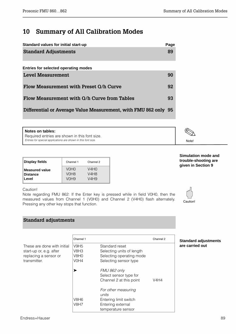
10 Summary of All Calibration Modes
Standard values for initial start-up Page
Standard Adjustments 89
Entries for selected operating modes
Level Measurement 90
Flow Measurement with Preset Q/h Curve 92
Flow Measurement with Q/h Curve from Tables 93
Differential or Average Value Measurement, with FMU 862 only 95
Notes on tables: Required entries are shown in this font size. Entries for special applications are shown in this font size.
Simulation mode andtrouble-shooting aregiven in Section 9
Caution!Note regarding FMU 862: If the Enter key is pressed while in field V0H0, then themeasured values from Channel 1 (V0H0) and Channel 2 (V4H0) flash alternately.Pressing any other key stops that function.
Standard adjustments
Standard adjustments are carried out
Note!
Display fields Channel 1 Channel 2
Measured valueDistanceLevel
V0H0V0H8V0H9
V4H0V4H8V4H9
Caution!
Channel 1 Channel 2
These are done with initialstart-up or, e.g. afterreplacing a sensor ortransmitter.
V9H5V8H3V8H0V0H4
V8H6V8H7
Standard resetSelecting units of lengthSelecting operating modeSelecting sensor type
FMU 862 onlySelect sensor type forChannel 2 at this point
For other measuring unitsEntering limit switchEntering externaltemperature sensor
V4H4
Prosonic FMU 860…862 Summary of All Calibration Modes
Endress+Hauser 89

Level Measurement
For mode (V8H0): 0 : Level, Channel 11 : Level, Channel 1 and Channel 2 3 : Level, Channel 2
Channel 1 FMU 862 only
Channel 2
Calibrate after
Channel 1
Suppress interference signals at poor
installation points (see Section 9)V0H1V0H2V0H3
»Empty« calibration»Full« calibrationLevel application
V4H1V4H2V4H3
Linearisation mode: (for examples see next pages)
• if volumetric units are to be measured• if values are displayed in special units given by customer.
0/4...20 mA is assigned to level
V8H1
V8H2
V0H5
V0H6V0H7
V3H4
V3H3
Current output 0/4...20 mA4 mA thresholdValue for 0/4 mAValue for 20 mAIntegration time
Output on fault:
Selecting fail-safe mode
If no echo present
--V4H5V4H6V4H7
V6H4
V6H3
Relay 5 is set in the factory for error indication V1H0
V1H1 (0)V1H2V1H3
V1H0V1H1 (2)V1H2V1H3
V1H0V1H1 (8)
V1H0V1H1 (0)V1H2V1H3
Limit relaySelecting relaySelecting »limit«Switch-on point for relaySwitch-off point for relay
Tendency relaySelecting relaySelecting »tendency«Switch-on point for relaySwitch-off point for relay
Fault relaySelecting relaySelecting »Error: 8«
Pump controlSelecting relaySelecting »Limit«Switch-on point for relaySwitch-off point for relay
V1H0V1H1 (1)V1H2V1H3
V1H0V1H1 (3)V1H2V1H3
V1H0V1H1 (8)
V1H0V1H1 (1)V1H2V1H3
V1H4
V1H9
Turn on alternating pump control
For all relays for pump control: enter the minimum time interval betweenthe switching of two relays.
V1H4
V1H9
FMU 862 only: Calibrate Channel 2 at this point
V9H1
V9H6
Reset last error code and Reset last but one error codeLocking (using 3-figure number)
-
-
% Level shown in V0H0or V4H0 for Channel 2
Analogue output is set
Measuring point data are entered.Matrix is locked.
Relay functions are setfor a maximum of five relays
Summary of All Calibration Modes Prosonic FMU 860…862
90 Endress+Hauser

Linearisation mode:
Channel 1 Channel 2
Measured value in unitsgiven by customerLinearisation for verticalcylindrical vesselMeasured value in units given bycustomer are shown in V0H0 or V4H0 for Channel 2
V2H7V2H0
Enter volume at 100%Activate (linear:0)
V5H7V5H0
Channel 1 Channel 2
Linearisation forhorizontal cylindrical vesselMeasured value in units givenby customer are shown inV0H0 or V4H0 for Channel 2
V2H6V2H7V2H0
Enter Vessel diameterEnter vessel volumeLinearisation (cyl, horiz.:1)
V5H6V5H7V5H0
Channel 1 Channel 2
Linearisation for anyshaped vessel given bythe values in table forthe vesselMeasured value in units given bycustomer are shown in V0H0 or V4H0 for Channel 2
V2H3V2H4V2H5
V2H0
Repeat following entriesEnter levelEnter volumeRegister next line number
Activate (manual:3)
V5H3V5H4V5H5
V5H0
Channel 1 Channel 2
Linearisation for anyshaped vessel by baling out from thevesselMeasured value in units given bycustomer are shown in V0H0 or V4H0 for Channel 2
V2H0
V2H3
V2H4V2H5
V2H0
Linearisation(semiautomatic:4)Repeat following entriesLevel is displayed
Enter volumeRegister next line number
Activate (manual:3)
V5H0
V5H3
V5H4V5H5
V5H0
Channel 1 Channel 2
Measured value in % level are shownin V0H0 or V4H0 for Channel 2
V2H0 Linearisation, linear(linear :1)
V5H0
Channel 1 Channel 2
Measured value in % level are shownin V0H0 or V4H0 for Channel 2
V2H0 Cancel linearisation(cancel :5) "Linearisationlinear" is then shown.
V5H0
Switching off linearisation
Cancelling all table values for linearisation
Note!
Notes on tables: Required entries are shown in this font size. Entries for special applications are shown in this font size.
Prosonic FMU 860…862 Summary of All Calibration Modes
Endress+Hauser 91
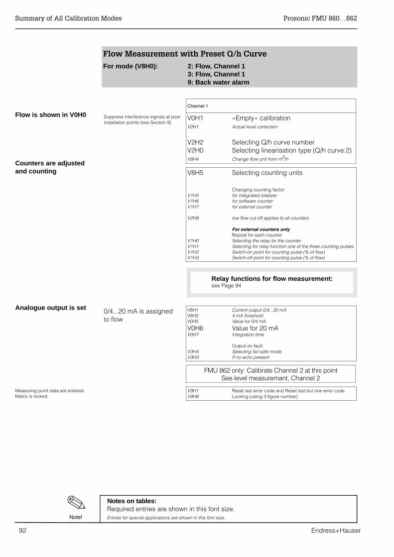
Flow Measurement with Preset Q/h Curve
For mode (V8H0): 2: Flow, Channel 13: Flow, Channel 19: Back water alarm
Channel 1
Suppress interference signals at poorinstallation points (see Section 9)
V0H1V2H1
V2H2V2H0V8H4
»Empty« calibrationActual level correction
Selecting Q/h curve numberSelecting linearisation type (Q/h curve:2)Change flow unit from m3/h
V8H5 Selecting counting units
V1H5V1H6V1H7
V2H8
V1H0V1H1V1H2V1H3
Changing counting factor:for integrated totalizerfor software counterfor external counter
low flow cut off applies to all counters
For external counters onlyRepeat for each counter:Selecting the relay for the counterSelecting for relay function one of the three counting pulsesSwitch-on point for counting pulse (% of flow)Switch-off point for counting pulse (% of flow)
0/4...20 mA is assigned to flow
V8H1V8H2V0H5
V0H6V0H7
V3H4V3H3
Current output 0/4...20 mA4 mA thresholdValue for 0/4 mA
Value for 20 mAIntegration time
Output on fault:Selecting fail-safe modeIf no echo present
FMU 862 only: Calibrate Channel 2 at this pointSee level measuremant, Channel 2
V9H1V9H6
Reset last error code and Reset last but one error codeLocking (using 3-figure number)
Counters are adjustedand counting
Flow is shown in V0H0
Analogue output is set
Measuring point data are entered.Matrix is locked.
Relay functions for flow measurement: see Page 94
Notes on tables: Required entries are shown in this font size. Entries for special applications are shown in this font size.Note!
Summary of All Calibration Modes Prosonic FMU 860…862
92 Endress+Hauser

Flow Measurement Q/h Curve from a Table
For mode (V8H0): 2: Flow, Channel 13: Flow, Channel 1 9: Back water alarm
Channel 1
Suppress interference signals at poorinstallation points (see Section 9)
V0H1V2H1
V8H4
V2H3V2H4V2H5
V2H0
»Empty« calibrationActual level correction
Selecting flow units
Repeat the following entriesEnter level heightEnter flowRegister next line number
Activate (manual:3)
V8H5 Selecting counting units
V1H5V1H6V1H7
V2H8
V1H0V1H1V1H2V1H3
Changing counting factor:for integrated totalizerfor software counterfor external counter
Low flow cut off applies to all counters
For external counters onlyRepeat for each counter:Selecting the relay for the counterSelecting for relay function one of the three counting pulsesSwitch-on point for counting pulse (% of flow)Switch-off point for counting pulse (% of flow)
0/4...20 mA is assigned to flow
V8H1V8H2V0H5
V0H6V0H7
V3H4V3H3
Current output 0/4...20 mA4 mA thresholdValue for 0/4 mA
Value for 20 mAIntegration time
Output on fault:Selecting fail-safe modeIf no echo present
FMU 862 only: Calibrate Channel 2 at this pointSee level measurement, Channel 2
V9H1V9H6
Reset last error code and Reset last but one error codeLocking (using 3-figure number)
Flow is shown in V0H0
Counters are adjustedand counting
Relay functions for otherrelays
Analogue output is set
Measuring point data are entered.Matrix is locked.
Notes on tables: Required entries are shown in this font size. Entries for special applications are shown in this font size. Note!
Relay functions for flow measurement: see Page 94
Prosonic FMU 860…862 Summary of All Calibration Modes
Endress+Hauser 93
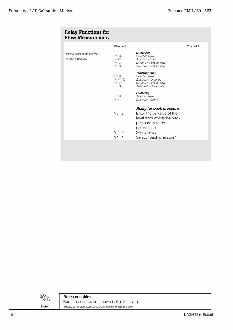
Relay Functions forFlow Measurement
Channel 1 Channel 2
Relay 5 is set in the factory
for error indicationV1H0V1H1V1H2V1H3
V1H0V1H1 (2)V1H2V1H3
V1H0 V1H1
Limit relaySelecting relaySelecting »limit«Switch-on point for relaySwitch-off point for relay
Tendency relaySelecting relaySelecting »tendency«Switch-on point for relaySwitch-off point for relay
Fault relaySelecting relaySelecting »Error: 8«
V5H8
V1H0V1H1
Relay for back pressureEnter the % value of thelevel from which the backpressure is to bedeterminedSelect relaySelect ”back pressure”
Notes on tables: Required entries are shown in this font size. Entries for special applications are shown in this font size.Note!
Summary of All Calibration Modes Prosonic FMU 860…862
94 Endress+Hauser
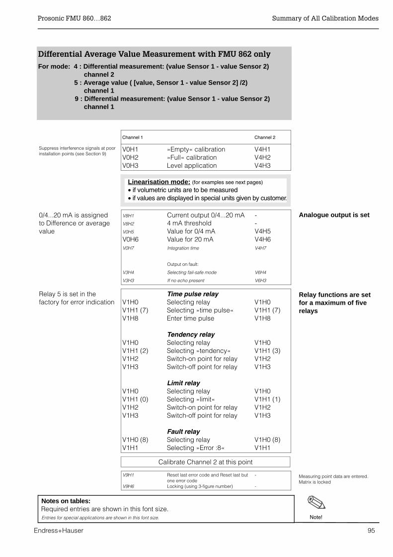
Analogue output is set
Relay functions are setfor a maximum of fiverelays
Measuring point data are entered.Matrix is locked
Channel 1 Channel 2
Suppress interference signals at poorinstallation points (see Section 9)
V0H1V0H2V0H3
»Empty« calibration»Full« calibrationLevel application
V4H1V4H2V4H3
Linearisation mode: (for examples see next pages)
• if volumetric units are to be measured• if values are displayed in special units given by customer.
0/4...20 mA is assigned to Difference or averagevalue
V8H1
V8H2
V0H5
V0H6V0H7
V3H4
V3H3
Current output 0/4...20 mA4 mA thresholdValue for 0/4 mAValue for 20 mAIntegration time
Output on fault:
Selecting fail-safe mode
If no echo present
--V4H5V4H6V4H7
V6H4
V6H3
Relay 5 is set in thefactory for error indication V1H0
V1H1 (7)V1H8
V1H0V1H1 (2)V1H2V1H3
V1H0V1H1 (0)V1H2V1H3
V1H0 (8)V1H1
Time pulse relaySelecting relaySelecting »time pulse«Enter time pulse
Tendency relaySelecting relay Selecting »tendency«Switch-on point for relaySwitch-off point for relay
Limit relaySelecting relaySelecting »limit«Switch-on point for relaySwitch-off point for relay
Fault relaySelecting relaySelecting »Error :8«
V1H0V1H1 (7)V1H8
V1H0V1H1 (3)V1H2V1H3
V1H0V1H1 (1)V1H2V1H3
V1H0 (8)V1H1
Calibrate Channel 2 at this point
V9H1
V9H6
Reset last error code and Reset last butone error codeLocking (using 3-figure number)
-
-
Differential Average Value Measurement with FMU 862 only
For mode: 4 : Differential measurement: (value Sensor 1 - value Sensor 2) channel 2 5 : Average value ( [value, Sensor 1 - value Sensor 2] /2) channel 1 9 : Differential measurement: (value Sensor 1 - value Sensor 2) channel 1
Notes on tables: Required entries are shown in this font size. Entries for special applications are shown in this font size. Note!
Prosonic FMU 860…862 Summary of All Calibration Modes
Endress+Hauser 95
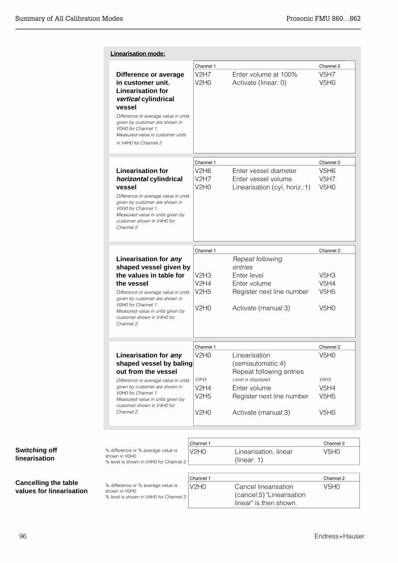
Linearisation mode:
Channel 1 Channel 2
Difference or average in customer unit.Linearisation for vertical cylindrical vesselDifference or average value in unitsgiven by customer are shown in V0H0 for Channel 1. Measured value in customer units
in V4H0 for Channel 2
V2H7V2H0
Enter volume at 100%Activate (linear: 0)
V5H7V5H0
Channel 1 Channel 2
Linearisation forhorizontal cylindricalvesselDifference or average value in unitsgiven by customer are shown in V0H0 for Channel 1. Measured value in units given bycustomer shown in V4H0 for Channel 2
V2H6V2H7V2H0
Enter vessel diameterEnter vessel volumeLinearisation (cyl, horiz.:1)
V5H6V5H7V5H0
Channel 1 Channel 2
Linearisation for anyshaped vessel given bythe values in table forthe vesselDifference or average value in unitsgiven by customer are shown in V0H0 for Channel 1. Measured value in units given bycustomer shown in V4H0 for Channel 2
V2H3V2H4V2H5
V2H0
Repeat following entriesEnter levelEnter volumeRegister next line number
Activate (manual:3)
V5H3V5H4V5H5
V5H0
Channel 1 Channel 2
Linearisation for anyshaped vessel by balingout from the vesselDifference or average value in unitsgiven by customer are shown in V0H0 for Channel 1. Measured value in units given bycustomer shown in V4H0 for Channel 2
V2H0
V2H3
V2H4V2H5
V2H0
Linearisation(semiautomatic:4)Repeat following entriesLevel is displayed
Enter volumeRegister next line number
Activate (manual:3)
V5H0
V5H3
V5H4V5H5
V5H0
Channel 1 Channel 2
% difference or % average value isshown in V0H0 % level is shown in V4H0 for Channel 2
V2H0 Linearisation, linear(linear: 1)
V5H0
Channel 1 Channel 2
% difference or % average value isshown in V0H0 % level is shown in V4H0 for Channel 2
V2H0 Cancel linearisation(cancel:5) "Linearisationlinear" is then shown.
V5H0
Switching offlinearisation
Cancelling the tablevalues for linearisation
Summary of All Calibration Modes Prosonic FMU 860…862
96 Endress+Hauser

Prosonic FMU 860...862 Kapitel 11: PROFIBUS-DP-Interface
Endress+Hauser 97
11 PROFIBUS-DP Interface
11.1 General notes on a PROFIBUS-DP network
11.1.1 Synopsis
Application PROFIBUS-DP is used primarily for factory automation. In PROFIBUS-PA systems for process automation, a PROFIBUS-DP system is used at the control level for quick trans-mission of the data. Here, a variant of PROFIBUS-DP, DPV1 is used. In addition to the cyclic exchange of data with a PLC, this allows the field devices to be configured via acyclic services. The principle technical data for DPV1 are listed in Table 2.1.
Participants Depending upon the application at hand, the participants in a PROFIBUS-DP system might be frequency converters, remote I/Os, actuators, sensors, links, gateways etc. as well as the PLC or process control system.
-
V H
Class1master
PLC
PROFIBUS-DP-slaves
PROFIBUS-DP
Class 2master
e.g.Commuwinor ToF Tool
Standard EN 50170, Parts 1 - 3, Version DPV1
Support PROFIBUS User Organisation (PNO)
Physical layer RS-485 and/or fibre optics
Max. length 1200 m (copper) or several kilometres (optics)
Participants Max. 126, including max. 32 as master
Transmission rate up to12 MBit/s (for FMU 860 ... 862: 1.5 Mbit/s)
Bus access method Token passing with master-slave
Tab. 2.1 Technical data PROFIBUS-DP

Kapitel 11: PROFIBUS-DP-Interface Prosonic FMU 860...862
98 Endress+Hauser
11.1.2 Topology
PROFIBUS-DP is based on a linear topology. For lower data transmission rates, a tree structure is also possible.
Cable EN 50 170 specifies two types of bus cable. For transmission rates up to 12Mbit/s, cable type A is recommended. The specification is given in Table 2.2
Structure The following points should be noted when the bus structure is being planned:• The max. permissible cable length depends upon the transmission rate. For PROFI-
BUS RS-485 cable of type A (see table 2.2) the dependency is as follows:
The maximum transmission rate is limited by the slowest instrument on the bus. The maximum rate of the Prosonic FMU is 1.5 Mbit/s. The FMU recognizes the rate present on the bus and adjusts its own rate automatically.
• A maximum of 32 participants per segment is allowed.• A terminating resistance must be installed at both ends of every segment
(ohmic load 220 Ω ).• The cable length and/or the number of participants can be increased by using repea-
ters.• There must never be more than three repeaters between any two participants• The total number of participants in the system is limited to 126 - (2x number of repea-
ters).
Spurs A spur is the cable connecting the field device to the T-box. As a rule of thumb:• For transmission rates up to 1500 kbits/s, the total length (sum) ot the spurs may not
exceed 6.6 m.• Spurs should not be used for transmission rates greater than 1500 kbits/s.
Examples Figs. 2.2 and 2.3 show examples for a linear and tree bus structure.
Fig. 2.2. shows that three repeaters are necessary if the PROFIBUS-DP system is to be developed to the full. The maximum cable length corresponds to 4x the value quoted in the table above. Since three repeaters are used, the maximum number of participants is reduced to 120.
Fig. 2.3. shows how several repeaters can be used to create a tree structure. The num-ber of participants allowable per segment is reduced by one per repeater: the total num-ber of participants is limited to 126 - (2x number of repeaters).
Terminator 135 Ω to 165 Ω at a measuring frequency of 3 MHz to 20 MHz
Cable capacitance < 30pF per Meter
Core cross-section >0.34 mm², corresponds to AWG 22
Cable type twisted pairs, 1x 2, 2x 2 or 1x4 core
Loop resistance 110 Ω per km
Signal attenuation max. 9 dB over the entire length of the segment
Screening woven copper sheath or woven sheath and foil sheath
Tab. 2.2 Specification of Cable type A of the PROFIBUS-DP standard
Transmission rate(kBit/s) 19,2 - 93,75 187,5 500 1500
Cable length(m) 1200 1000 400 200

Prosonic FMU 860...862 Kapitel 11: PROFIBUS-DP-Interface
Endress+Hauser 99
1
1
1
1
2
2
2
2
3
3
3
3
T
T
T
T
T
T
T
T
31
31
30
30
R1
R3
R2
trunk cable
segment 1
segment 2
segment 3
1
1
1
1
2
2
2
2
3
3
3
3
T
T
T
T
T
T
T
T
31
31
29
29
R3
R2
R1
trunk cable
segment 1
segment 2
segment 3
Abb. 2.2 PROFIBUS-DP system with linear structureT = terminatorR = repeater 1...n = max. number of field de-vices on a segment
Abb. 2.3 PROFIBUS-DP system with tree structureT = terminator R = repeater1...n = max. number of field de-vices on a segment
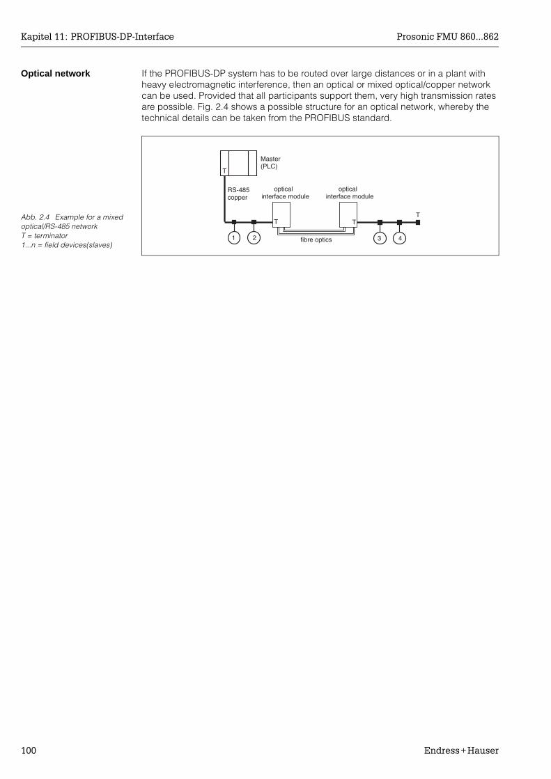
Kapitel 11: PROFIBUS-DP-Interface Prosonic FMU 860...862
100 Endress+Hauser
Optical network If the PROFIBUS-DP system has to be routed over large distances or in a plant with heavy electromagnetic interference, then an optical or mixed optical/copper network can be used. Provided that all participants support them, very high transmission rates are possible. Fig. 2.4 shows a possible structure for an optical network, whereby the technical details can be taken from the PROFIBUS standard.
1 32 4
TTT
T
Master(PLC)
RS-485copper
opticalinterface module
opticalinterface module
fibre optics
Abb. 2.4 Example for a mixed optical/RS-485 networkT = terminator1...n = field devices(slaves)
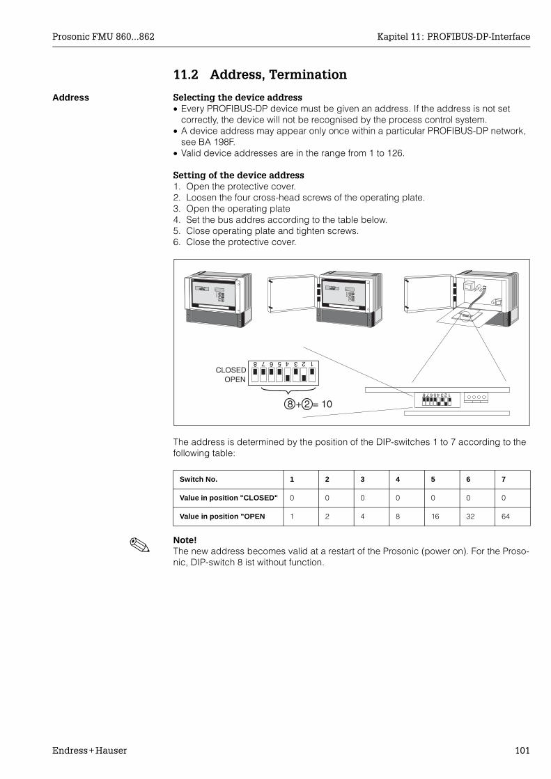
Prosonic FMU 860...862 Kapitel 11: PROFIBUS-DP-Interface
Endress+Hauser 101
11.2 Address, Termination
Address Selecting the device address• Every PROFIBUS-DP device must be given an address. If the address is not set
correctly, the device will not be recognised by the process control system.• A device address may appear only once within a particular PROFIBUS-DP network,
see BA 198F.• Valid device addresses are in the range from 1 to 126.
Setting of the device address1. Open the protective cover.2. Loosen the four cross-head screws of the operating plate.3. Open the operating plate4. Set the bus addres according to the table below.5. Close operating plate and tighten screws.6. Close the protective cover.
The address is determined by the position of the DIP-switches 1 to 7 according to the following table:
!Note!The new address becomes valid at a restart of the Prosonic (power on). For the Proso-nic, DIP-switch 8 ist without function.
Switch No. 1 2 3 4 5 6 7
Value in position "CLOSED" 0 0 0 0 0 0 0
Value in position "OPEN 1 2 4 8 16 32 64
4 123568 7
8 + 2 = 10
OPENCLOSED
4 123568 7

Kapitel 11: PROFIBUS-DP-Interface Prosonic FMU 860...862
102 Endress+Hauser
Termination • At the last instrument on the bus, a terminating resistance must be switched on at DIP-switch SW 2: OFF, ON, ON, OFF.
• Optionally, the bus power can be supplied by this instrument: ON, ON, ON, ON.• At the remaining instruments the terminating resistance must be switche off: OFF, OFF,
OFF, OFF.
SW2
ONOFF
+5V
ONOFF
ONOFF
TerminationON
Termination andbus power
ON
Termination andbus power
OFF
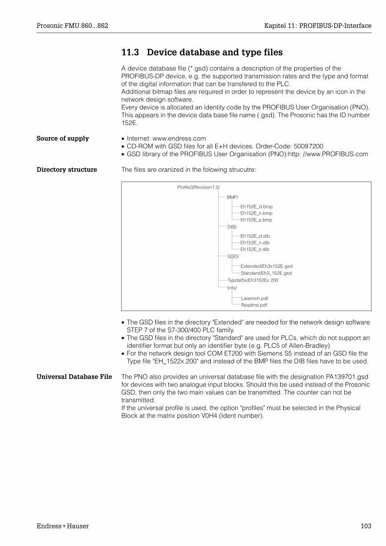
Prosonic FMU 860...862 Kapitel 11: PROFIBUS-DP-Interface
Endress+Hauser 103
11.3 Device database and type files
A device database file (*.gsd) contains a description of the properties of thePROFIBUS-DP device, e.g. the supported transmission rates and the type and format of the digital information that can be transfered to the PLC. Additional bitmap files are required in order to represent the device by an icon in the network design software. Every device is allocated an identity code by the PROFIBUS User Organisation (PNO). This appears in the device data base file name (.gsd). The Prosonic has the ID number 152E.
Source of supply • Internet: www.endress.com• CD-ROM with GSD files for all E+H devices. Order-Code: 50097200• GSD library of the PROFIBUS User Organisation (PNO):http: //www.PROFIBUS.com
Directory structure The files are oranized in the folowing strucutre:
• The GSD files in the directory "Extended" are needed for the network design software STEP 7 of the S7-300/400 PLC family.
• The GSD files in the directory "Standard" are used for PLCs, which do not support an identifier format but only an identifier byte (e.g. PLC5 of Allen-Bradley)
• For the network design tool COM ET200 with Siemens S5 instead of an GSD file the Type file "EH_1522x.200" and instead of the BMP files the DIB files have to be used.
Universal Database File The PNO also provides an universal database file with the designation PA139701.gsd for devices with two analogue input blocks. Should this be used instead of the Prosonic GSD, then only the two main values can be transmitted. The counter can not be transmitted.If the universal profile is used, the option "profiles" must be selected in the Physical Block at the matrix position V0H4 (Ident number).
Profile3/Revision1.0/
BMP/
Eh152E_d.bmpEh152E_n.bmpEh152E_s.bmp
DIB/
Eh152E_d.dibEh152E_n.dibEh152E_s.dib
GSD/
Extended/Eh3x152E.gsd
Standard/Eh3_152E.gsd
Typdat5x/Eh3152Ex.200
Info/
Liesmich.pdfReadme.pdf

Kapitel 11: PROFIBUS-DP-Interface Prosonic FMU 860...862
104 Endress+Hauser
11.4 Cyclic data exchange
Block model of theProsonic FMU 860/861/862
The block model shows, which data are exchanged continously (i.e. by cyclic data transfer) between the Prosonic and the PLC.
Modules for the cyclic data telegram
For the cyclic data telegram the Prosonic provides the following modules:1. Analog Input
Depending on the configuration (see below) this is main value 1 (V0H0) or main value 2 (V4H0). Before they are sent to the PLC these values may be scaled in the respective Analog Input Block.
2. CounterThis flow counter is composed of the matrix fields V8H8 (counter high) and V8H9 (counter low).
3. EmptyThis module must be applied during configuration (see below), if main value 2 is not to appear in the data telegram.
Configuration of thecyclic data telegram
Use the configuration software of your PLC in order to compose the data telegram from these modules in one of the following ways:1. Main value 1
In order to transmit only main value 1, select the module Analog Input.2. Main value 1 and flow counter
In order to transmit main value 1 and the flow counter, select the modules in the fol-lowing order: Analog Input, Empty, Counter.
3. Main value 1 and main value 2In order to transmit both main values , select Analog Input twice.
4. Main value 1, main value 2 and flow counterIn order to transmit both main values and the flow counter, select the modules in the following order: Analog Input, Analog Input, Counter.
The exact way of performing the configuration depends on the configuration software of the PLC.
Analog-InputBlock AI1
Analog-InputBlock AI2
TransducerBlock TBAux
TransducerBlock TB1
TransducerBlock TB2
sensor 1
sensor 2
status
status
status
value
value
value
e.g.PLC
Sensor 2, Transducer Block 2 and Analog Input Block 2are provided by FMU 862 only.The flow counter is provided by FMU 861/862 only.
signal evaluationcalibrationlinearisation
scaling,status
V0H0
V4H0
flow counterV8H8/V8H9
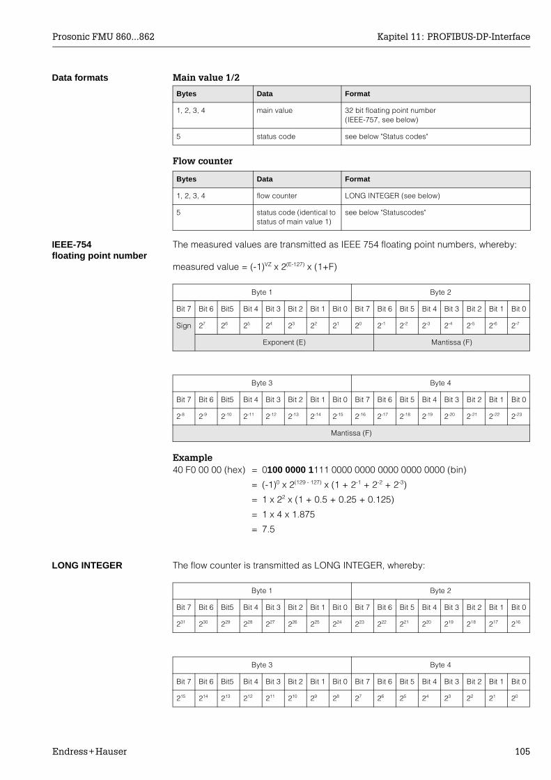
Prosonic FMU 860...862 Kapitel 11: PROFIBUS-DP-Interface
Endress+Hauser 105
Data formats Main value 1/2
Flow counter
IEEE-754 floating point number
The measured values are transmitted as IEEE 754 floating point numbers, whereby:
measured value = (-1)VZ x 2(E-127) x (1+F)
Example
LONG INTEGER The flow counter is transmitted as LONG INTEGER, whereby:
Bytes Data Format
1, 2, 3, 4 main value 32 bit floating point number(IEEE-757, see below)
5 status code see below "Status codes"
Bytes Data Format
1, 2, 3, 4 flow counter LONG INTEGER (see below)
5 status code (identical to status of main value 1)
see below "Statuscodes"
Byte 1 Byte 2
Bit 7 Bit 6 Bit5 Bit 4 Bit 3 Bit 2 Bit 1 Bit 0 Bit 7 Bit 6 Bit 5 Bit 4 Bit 3 Bit 2 Bit 1 Bit 0
Sign 27 26 25 24 23 22 21 20 2-1 2-2 2-3 2-4 2-5 2-6 2-7
Exponent (E) Mantissa (F)
Byte 3 Byte 4
Bit 7 Bit 6 Bit5 Bit 4 Bit 3 Bit 2 Bit 1 Bit 0 Bit 7 Bit 6 Bit 5 Bit 4 Bit 3 Bit 2 Bit 1 Bit 0
2-8 2-9 2-10 2-11 2-12 2-13 2-14 2-15 2-16 2-17 2-18 2-19 2-20 2-21 2-22 2-23
Mantissa (F)
40 F0 00 00 (hex) = 0100 0000 1111 0000 0000 0000 0000 0000 (bin)
= (-1)0 x 2(129 - 127) x (1 + 2-1 + 2-2 + 2-3)
= 1 x 22 x (1 + 0.5 + 0.25 + 0.125)
= 1 x 4 x 1.875
= 7.5
Byte 1 Byte 2
Bit 7 Bit 6 Bit5 Bit 4 Bit 3 Bit 2 Bit 1 Bit 0 Bit 7 Bit 6 Bit 5 Bit 4 Bit 3 Bit 2 Bit 1 Bit 0
231 230 229 228 227 226 225 224 223 222 221 220 219 218 217 216
Byte 3 Byte 4
Bit 7 Bit 6 Bit5 Bit 4 Bit 3 Bit 2 Bit 1 Bit 0 Bit 7 Bit 6 Bit 5 Bit 4 Bit 3 Bit 2 Bit 1 Bit 0
215 214 213 212 211 210 29 28 27 26 25 24 23 22 21 20

Kapitel 11: PROFIBUS-DP-Interface Prosonic FMU 860...862
106 Endress+Hauser
Status codes The status codes comprise one byte and have got the following meaning:
Status-Code
Device status Significance
00 Hex BAD non-specific
1F Hex BAD out-of-service (target mode)
40 Hex UNCERTAIN non-specific (simulation)
47 Hex UNCERTAIN last usable value(Fail-safe-Mode aktiv)
48 Hex UNCERTAIN Ersatzmenge(fail-Safe mode active)
4C Hex UNCERTAIN initial value(fail-Safe mode active)
5C Hex UNCERTAIN Configuration error(limits not set correctly)
80 Hex GOOD OK
84 Hex GOOD Active block alarm(static revision counter incremented)
89 Hex GOOD LOW_LIM (alarm active)
8A Hex GOOD HI_LIM (alarm active)
8D Hex GOOD LOW_LOW_LIM (alarm active)
8E Hex GOOD HI_HI_LIM (alarm active)
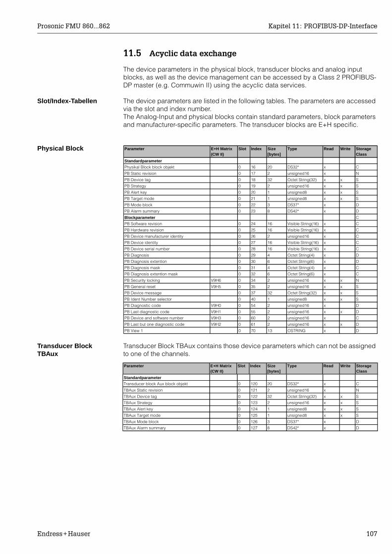
Prosonic FMU 860...862 Kapitel 11: PROFIBUS-DP-Interface
Endress+Hauser 107
11.5 Acyclic data exchange
The device parameters in the physical block, transducer blocks and analog input blocks, as well as the device management can be accessed by a Class 2 PROFIBUS-DP master (e.g. Commuwin II) using the acyclic data services.
Slot/Index-Tabellen The device parameters are listed in the following tables. The parameters are accessed via the slot and index number.The Analog-Input and physical blocks contain standard parameters, block parameters and manufacturer-specific parameters. The transducer blocks are E+H specific.
Physical Block
Transducer Block TBAux
Transducer Block TBAux contains those device parameters which can not be assigned to one of the channels.
Parameter E+H Matrix (CW II)
Slot Index Size[bytes]
Type Read Write Storage Class
Standardparameter
Physikal Block block objekt 0 16 20 DS32* x C
PB Static revision 0 17 2 unsigned16 x N
PB Device tag 0 18 32 Octet String(32) x x S
PB Strategy 0 19 2 unsigned16 x x S
PB Alert key 0 20 1 unsigned8 x x S
PB Target mode 0 21 1 unsigned8 x x S
PB Mode block 0 22 3 DS37* x D
PB Alarm summary 0 23 8 DS42* x D
Blockparameter C
PB Software revision 0 24 16 Visible String(16) x C
PB Hardware revision 0 25 16 Visible String(16) x C
PB Device manufacturer identity 0 26 2 unsigned16 x C
PB Device identity 0 27 16 Visible String(16) x C
PB Device serial number 0 28 16 Visible String(16) x C
PB Diagnosis 0 29 4 Octet String(4) x D
PB Diagnosis extention 0 30 6 Octet String(6) x D
PB Diagnosis mask 0 31 4 Octet String(4) x C
PB Diagnosis extention mask 0 32 6 Octet String(6) x C
PB Security locking V9H6 0 34 2 unsigned16 x x N
PB General reset V9H5 0 35 2 unsigned16 x x S
PB Device message 0 37 32 Octet String(32) x x S
PB Ident Number selector 0 40 1 unsigned8 x x S
PB Diagnostic code V9H0 0 54 2 unsigned16 x D
PB Last diagnostic code V9H1 0 55 2 unsigned16 x x D
PB Device and software number V9H3 0 60 2 unsigned16 x C
PB Last but one diagnostic code V9H2 0 61 2 unsigned16 x x D
PB View 1 0 70 13 OSTRING x D
Parameter E+H Matrix (CW II)
Slot Index Size[bytes]
Type Read Write Storage Class
Standardparameter
Transducer block Aux block objekt 0 120 20 DS32* x C
TBAux Static revision 0 121 2 unsigned16 x N
TBAux Device tag 0 122 32 Octet String(32) x x S
TBAux Strategy 0 123 2 unsigned16 x x S
TBAux Alert key 0 124 1 unsigned8 x x S
TBAux Target mode 0 125 1 unsigned8 x x S
TBAux Mode block 0 126 3 DS37* x D
TBAux Alarm summary 0 127 8 DS42* x D

Kapitel 11: PROFIBUS-DP-Interface Prosonic FMU 860...862
108 Endress+Hauser
Device management
Analog Input Block AI1 Analog Input Block 1 transmits the measured value of channel 1. It is connected to the Transducer Block TB 1 and contains the following parameters:
Transducer Block TB1 Transducer Block TB 1 contains the device parameters for channel 1.
Parameter E+H Matrix (CW II)
Slot Index Size[bytes]
Type Read Write Storage Class
Parameter E+H Matrix (CW II)
Slot Index Size[bytes]
Type Read Write Storage Class
Directory objekt header 1 0 12 OSTRING x C
Composite list directory entries 1 1 24 OSTRING x C
Parameter E+H Matrix (CW II)
Slot Index Size[bytes]
Type Read Write Storage Class
E+H-Parameter
TBAux Relay selection V1H0 0 128 1 unsigned8 x x S
TBAux Relay funktion V1H1 0 129 1 unsigned8 x x S
TBAux Switch-on point V1H2 0 130 4 floating point x x S
TBAux Switch-off point V1H3 0 131 4 floating point x x S
TBAux Alternating pump control V1H4 0 132 1 unsigned8 x x S
TBAux Count factor C1 V1H5 0 133 4 floating point x x S
TBAux Count factor C2 V1H6 0 134 4 floating point x x S
TBAux Count factor C3 V1H7 0 135 4 floating point x x S
TBAux Internal time V1H8 0 136 2 unsigned16 x x S
TBAux Switch delay V1H9 0 137 1 unsigned8 x x S
TBAux Operating mode V8H0 0 138 1 unsigned8 x x S
TBAux Select current V8H1 0 139 1 unsigned8 x x S
TBAux 4 mA threshold V8H2 0 140 1 unsigned8 x x S
TBAux Select distance unit V8H3 0 141 1 unsigned8 x x S
TBAux Flow unit V8H4 0 142 1 unsigned8 x x S
TBAux Counter unit V8H5 0 143 1 unsigned8 x x S
TBAux Limit switch V8H6 0 144 1 unsigned8 x x S
TBAux External temperatur sensor V8H7 0 145 1 unsigned8 x x S
TBAux Internal counter high V8H8 0 146 2 unsigned16 x S
TBAux Internal counter low V8H9 0 147 2 unsigned16 x S
TBAux Reset counter V9H4 0 148 2 unsigned16 x x D
TBAux Simulation level V9H7 0 149 4 floating point x x S
TBAux Simulation volume V9H8 0 150 4 floating point x x S
TBAux Simulation current V9H9 0 151 4 floating point x x S
TBAux View1 0 152 13 OSTRING x D
Standardparameter
Analog input block 1 block objekt 1 16 20 DS32* x C
AI1 Static revision 1 17 2 unsigned16 x N
AI1 Device tag 1 18 32 Octet String(32) x x S
AI1 Strategy 1 19 2 unsigned16 x x S
AI1 Alert key 1 20 1 unsigned8 x x S
AI1 Target Mode 1 21 1 unsigned8 x x S
AI1 Mode block 1 22 3 DS37* x D
AI1 Alarm summary 1 23 8 DS42* x D
Blockparameter
AI1 OUT 1 26 5 DS33* x D
AI1 PV_SCALE 1 27 8 floating point(2) x x S
AI1 OUT_SCALE 1 28 11 DS36* x x S
AI1 LIN_TYPE 1 29 1 unsigned8 x x S
AI1 CHANNEL 1 30 2 unsigned16 x x S
AI1 PV_FTIME 1 32 4 floating point x x S
AI1 ALARM_HYSTERESIS 1 35 4 floating point x x S
AI1 HI_HI_LIMIT 1 37 4 floating point x x S
AI1 HI_LIMIT 1 39 4 floating point x x S
AI1 LO_LIMIT 1 41 4 floating point x x S
AI1 LO_LO_LIMIT 1 42 4 floating point x x S
AI1 HI_HI_ALM 1 46 16 DS39* x D
AI1 HI_ALM 1 47 16 DS39* x D
AI1 LO_ALM 1 48 16 DS39* x D
AI1 LO_LO_ALM 1 49 16 DS39* x D
AI1 SIMULATE 1 50 6 DS50* x x S
AI1 OUT_UNIT_TEXT 1 51 16 Octet String(16) x x S
AI1 View1 1 61 13 OSTRING x D
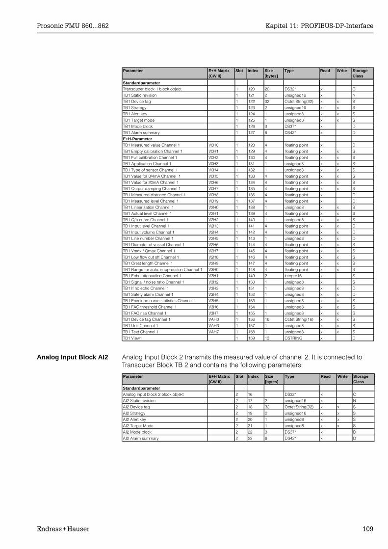
Prosonic FMU 860...862 Kapitel 11: PROFIBUS-DP-Interface
Endress+Hauser 109
Analog Input Block AI2 Analog Input Block 2 transmits the measured value of channel 2. It is connected to Transducer Block TB 2 and contains the following parameters:
Parameter E+H Matrix (CW II)
Slot Index Size[bytes]
Type Read Write Storage Class
Parameter E+H Matrix (CW II)
Slot Index Size[bytes]
Type Read Write Storage Class
Standardparameter
Transducer block 1 block object 1 120 20 DS32* x C
TB1 Static revision 1 121 2 unsigned16 x N
TB1 Device tag 1 122 32 Octet String(32) x x S
TB1 Strategy 1 123 2 unsigned16 x x S
TB1 Alert key 1 124 1 unsigned8 x x S
TB1 Target mode 1 125 1 unsigned8 x x S
TB1 Mode block 1 126 3 DS37* x D
TB1 Alarm summary 1 127 8 DS42* x D
E+H-Parameter
TB1 Measured value Channel 1 V0H0 1 128 4 floating point x D
TB1 Empty calibration Channel 1 V0H1 1 129 4 floating point x x S
TB1 Full calibration Channel 1 V0H2 1 130 4 floating point x x S
TB1 Application Channel 1 V0H3 1 131 1 unsigned8 x x S
TB1 Type of sensor Channel 1 V0H4 1 132 1 unsigned8 x x S
TB1 Value for 0/4mA Channel 1 V0H5 1 133 4 floating point x x S
TB1 Value for 20mA Channel 1 V0H6 1 134 4 floating point x x S
TB1 Output damping Channel 1 V0H7 1 135 4 floating point x x S
TB1 Measured distance Channel 1 V0H8 1 136 4 floating point x D
TB1 Measured level Channel 1 V0H9 1 137 4 floating point x D
TB1 Linearization Channel 1 V2H0 1 138 1 unsigned8 x x S
TB1 Actual level Channel 1 V2H1 1 139 4 floating point x x S
TB1 Q/h curve Channel 1 V2H2 1 140 1 unsigned8 x x S
TB1 Input level Channel 1 V2H3 1 141 4 floating point x x D
TB1 Input volume Channel 1 V2H4 1 142 4 floating point x x D
TB1 Line number Channel 1 V2H5 1 143 1 unsigned8 x x D
TB1 Diameter of vessel Channel 1 V2H6 1 144 4 floating point x x S
TB1 Vmax / Qmax Channel 1 V2H7 1 145 4 floating point x x S
TB1 Low flow cut off Channel 1 V2H8 1 146 4 floating point x x S
TB1 Crest length Channel 1 V2H9 1 147 4 floating point x x S
TB1 Range for auto. suppression Channel 1 V3H0 1 148 4 floating point x x S
TB1 Echo attenuation Channel 1 V3H1 1 149 2 integer16 x S
TB1 Signal / noise ratio Channel 1 V3H2 1 150 1 unsigned8 x S
TB1 If no echo Channel 1 V3H3 1 151 1 unsigned8 x x D
TB1 Safety alarm Channel 1 V3H4 1 152 1 unsigned8 x x D
TB1 Envelope curve statistics Channel 1 V3H5 1 153 1 unsigned8 x x S
TB1 FAC threshold Channel 1 V3H6 1 154 1 unsigned8 x x S
TB1 FAC rise Channel 1 V3H7 1 155 1 unsigned8 x x S
TB1 Device tag Channel 1 VAH0 1 156 16 Octet String(16) x x S
TB1 Unit Channel 1 VAH3 1 157 1 unsigned8 x x S
TB1 Text Channel 1 VAH7 1 158 1 unsigned8 x x S
TB1 View1 1 159 13 OSTRING x D
Standardparameter
Analog input block 2 block objekt 2 16 DS32* x C
AI2 Static revision 2 17 2 unsigned16 x N
AI2 Device tag 2 18 32 Octet String(32) x x S
AI2 Strategy 2 19 2 unsigned16 x x S
AI2 Alert key 2 20 1 unsigned8 x x S
AI2 Target Mode 2 21 1 unsigned8 x x S
AI2 Mode block 2 22 3 DS37* x D
AI2 Alarm summary 2 23 8 DS42* x D
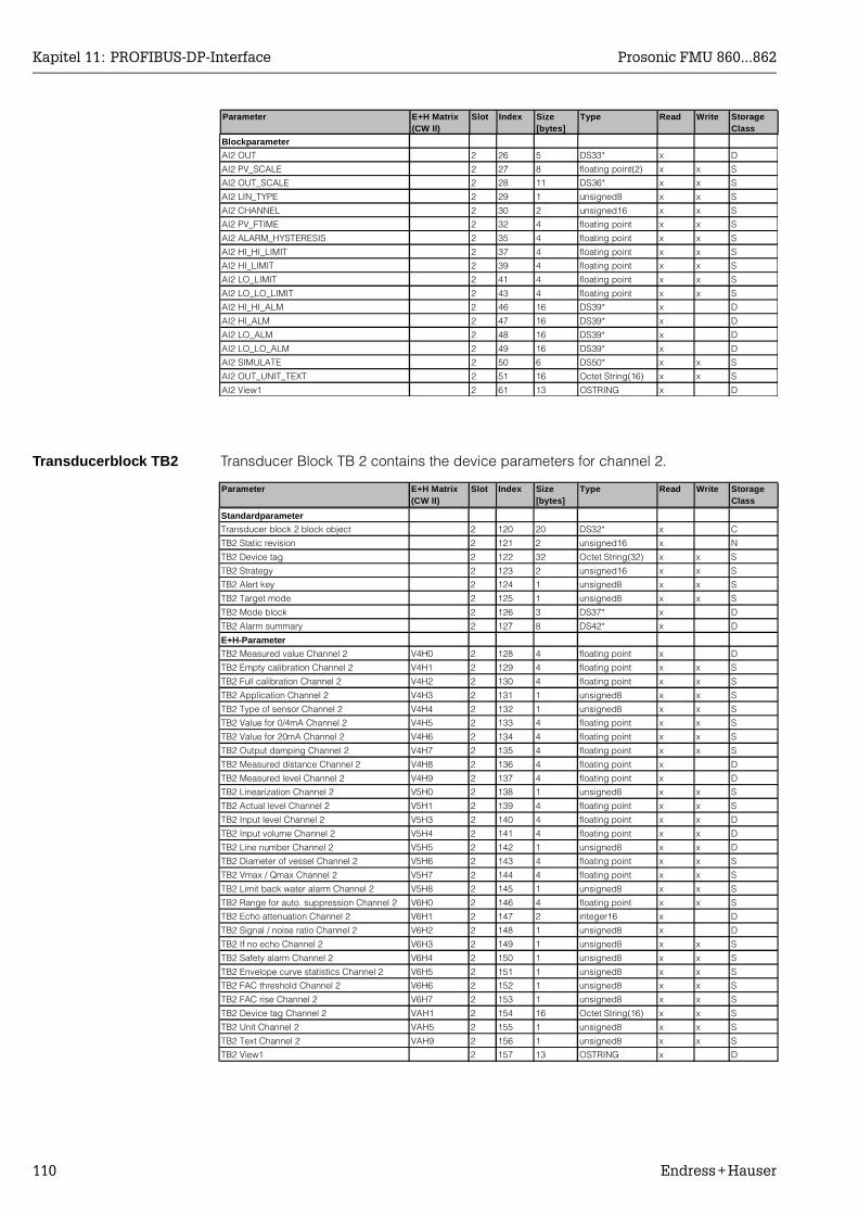
Kapitel 11: PROFIBUS-DP-Interface Prosonic FMU 860...862
110 Endress+Hauser
Transducerblock TB2 Transducer Block TB 2 contains the device parameters for channel 2.
Parameter E+H Matrix (CW II)
Slot Index Size[bytes]
Type Read Write Storage Class
Blockparameter
AI2 OUT 2 26 5 DS33* x D
AI2 PV_SCALE 2 27 8 floating point(2) x x S
AI2 OUT_SCALE 2 28 11 DS36* x x S
AI2 LIN_TYPE 2 29 1 unsigned8 x x S
AI2 CHANNEL 2 30 2 unsigned16 x x S
AI2 PV_FTIME 2 32 4 floating point x x S
AI2 ALARM_HYSTERESIS 2 35 4 floating point x x S
AI2 HI_HI_LIMIT 2 37 4 floating point x x S
AI2 HI_LIMIT 2 39 4 floating point x x S
AI2 LO_LIMIT 2 41 4 floating point x x S
AI2 LO_LO_LIMIT 2 43 4 floating point x x S
AI2 HI_HI_ALM 2 46 16 DS39* x D
AI2 HI_ALM 2 47 16 DS39* x D
AI2 LO_ALM 2 48 16 DS39* x D
AI2 LO_LO_ALM 2 49 16 DS39* x D
AI2 SIMULATE 2 50 6 DS50* x x S
AI2 OUT_UNIT_TEXT 2 51 16 Octet String(16) x x S
AI2 View1 2 61 13 OSTRING x D
Parameter E+H Matrix (CW II)
Slot Index Size[bytes]
Type Read Write Storage Class
Standardparameter
Transducer block 2 block object 2 120 20 DS32* x C
TB2 Static revision 2 121 2 unsigned16 x N
TB2 Device tag 2 122 32 Octet String(32) x x S
TB2 Strategy 2 123 2 unsigned16 x x S
TB2 Alert key 2 124 1 unsigned8 x x S
TB2 Target mode 2 125 1 unsigned8 x x S
TB2 Mode block 2 126 3 DS37* x D
TB2 Alarm summary 2 127 8 DS42* x D
E+H-Parameter
TB2 Measured value Channel 2 V4H0 2 128 4 floating point x D
TB2 Empty calibration Channel 2 V4H1 2 129 4 floating point x x S
TB2 Full calibration Channel 2 V4H2 2 130 4 floating point x x S
TB2 Application Channel 2 V4H3 2 131 1 unsigned8 x x S
TB2 Type of sensor Channel 2 V4H4 2 132 1 unsigned8 x x S
TB2 Value for 0/4mA Channel 2 V4H5 2 133 4 floating point x x S
TB2 Value for 20mA Channel 2 V4H6 2 134 4 floating point x x S
TB2 Output damping Channel 2 V4H7 2 135 4 floating point x x S
TB2 Measured distance Channel 2 V4H8 2 136 4 floating point x D
TB2 Measured level Channel 2 V4H9 2 137 4 floating point x D
TB2 Linearization Channel 2 V5H0 2 138 1 unsigned8 x x S
TB2 Actual level Channel 2 V5H1 2 139 4 floating point x x S
TB2 Input level Channel 2 V5H3 2 140 4 floating point x x D
TB2 Input volume Channel 2 V5H4 2 141 4 floating point x x D
TB2 Line number Channel 2 V5H5 2 142 1 unsigned8 x x D
TB2 Diameter of vessel Channel 2 V5H6 2 143 4 floating point x x S
TB2 Vmax / Qmax Channel 2 V5H7 2 144 4 floating point x x S
TB2 Limit back water alarm Channel 2 V5H8 2 145 1 unsigned8 x x S
TB2 Range for auto. suppression Channel 2 V6H0 2 146 4 floating point x x S
TB2 Echo attenuation Channel 2 V6H1 2 147 2 integer16 x D
TB2 Signal / noise ratio Channel 2 V6H2 2 148 1 unsigned8 x D
TB2 If no echo Channel 2 V6H3 2 149 1 unsigned8 x x S
TB2 Safety alarm Channel 2 V6H4 2 150 1 unsigned8 x x S
TB2 Envelope curve statistics Channel 2 V6H5 2 151 1 unsigned8 x x S
TB2 FAC threshold Channel 2 V6H6 2 152 1 unsigned8 x x S
TB2 FAC rise Channel 2 V6H7 2 153 1 unsigned8 x x S
TB2 Device tag Channel 2 VAH1 2 154 16 Octet String(16) x x S
TB2 Unit Channel 2 VAH5 2 155 1 unsigned8 x x S
TB2 Text Channel 2 VAH9 2 156 1 unsigned8 x x S
TB2 View1 2 157 13 OSTRING x D
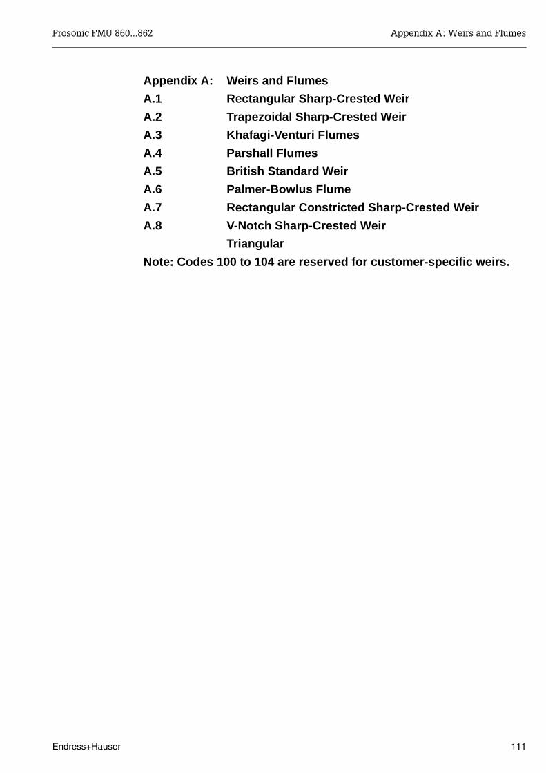
Appendix A: Weirs and Flumes
A.1 Rectangular Sharp-Crested Weir
A.2 Trapezoidal Sharp-Crested Weir
A.3 Khafagi-Venturi Flumes
A.4 Parshall Flumes
A.5 British Standard Weir
A.6 Palmer-Bowlus Flume
A.7 Rectangular Constricted Sharp-Crested Weir
A.8 V-Notch Sharp-Crested Weir
Triangular
Note: Codes 100 to 104 are reserved for customer-specific weirs.
Prosonic FMU 860...862 Appendix A: Weirs and Flumes
Endress+Hauser 111

A.1 Rectangular Sharp-Crested Weir
V2H2 Code B (mm) Hmax (mm) Qmax (m3/h)0 1000 500 24181 1000 1500 12567
The Q/h-curves can be made to fit other crest lengths. For crest length greater than 8.5 m for Code 0 (or greater than 1.65 m for Code 1).Select greater flow units than m3/h such as, e.g. m3/sec.(The largest value which can be displayed is 19999)
The factory setting for the current output assigns a maximum flowrate Qmax = 100 tothe 20 mA current. After entering a characteristic code, the maximum flow exceeds this vale and causesa signal overrun. If you want to use the current output, then enter the flow value in V0H6 which isassigned to the 20 mA signal.
Note!
Step Matrix Entry Meaning1 V2H2 e.g. 1 Select the code with Hmax of the weir.2 - »E« Confirm entry3 V2H9 e.g. 2 Give the weir throat in [m]4 - »E« Confirm entry5 V2H0 2 Enter 2 for the Q/h-curve6 - »E« Confirm entry and activate curve
Crest length B
Hmax
k k
min. 3 Hmax
45°
blocking distanceFDU 80 = 0.3 m
k = approx. 3 mm
or
weir plate
channel floor
drawdown
Direction of flow
BD
min.2 Hmax
Adjusting a Q/h curve tothe correct crest length
Tab. A.1Pre-programmed drawdownweirs with rectangular section
Appendix A: Weirs and Flumes Prosonic FMU 860...862
112 Endress+Hauser
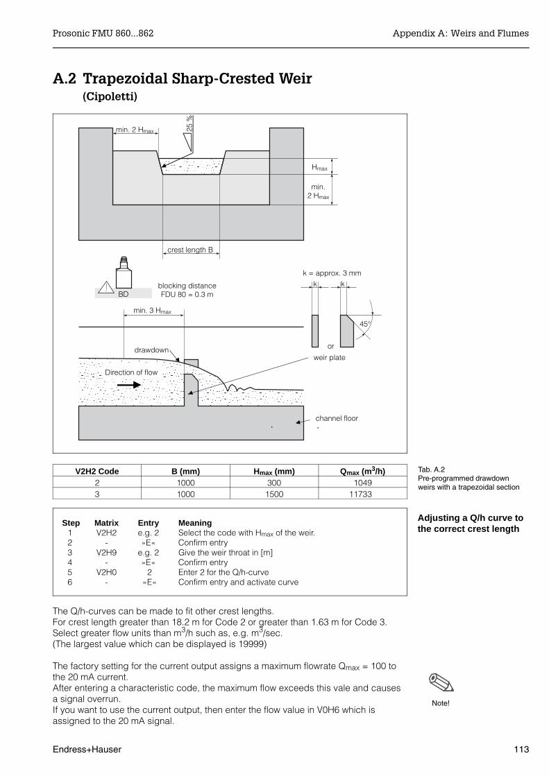
A.2 Trapezoidal Sharp-Crested Weir(Cipoletti)
V2H2 Code B (mm) Hmax (mm) Qmax (m3/h)2 1000 300 10493 1000 1500 11733
The Q/h-curves can be made to fit other crest lengths. For crest length greater than 18.2 m for Code 2 or greater than 1.63 m for Code 3.Select greater flow units than m3/h such as, e.g. m3/sec.(The largest value which can be displayed is 19999)
The factory setting for the current output assigns a maximum flowrate Qmax = 100 tothe 20 mA current. After entering a characteristic code, the maximum flow exceeds this vale and causesa signal overrun. If you want to use the current output, then enter the flow value in V0H6 which isassigned to the 20 mA signal.
Note!
Step Matrix Entry Meaning1 V2H2 e.g. 2 Select the code with Hmax of the weir.2 - »E« Confirm entry3 V2H9 e.g. 2 Give the weir throat in [m]4 - »E« Confirm entry5 V2H0 2 Enter 2 for the Q/h-curve6 - »E« Confirm entry and activate curve
crest length B
Hmax
k k
min. 3 Hmax
45°
blocking distanceFDU 80 = 0.3 m
k = approx. 3 mm
or
weir plate
channel floor
drawdown
Direction of flow
BD
min.2 Hmax
min. 2 Hmax 25 %
Tab. A.2Pre-programmed drawdownweirs with a trapezoidal section
Adjusting a Q/h curve tothe correct crest length
Prosonic FMU 860...862 Appendix A: Weirs and Flumes
Endress+Hauser 113
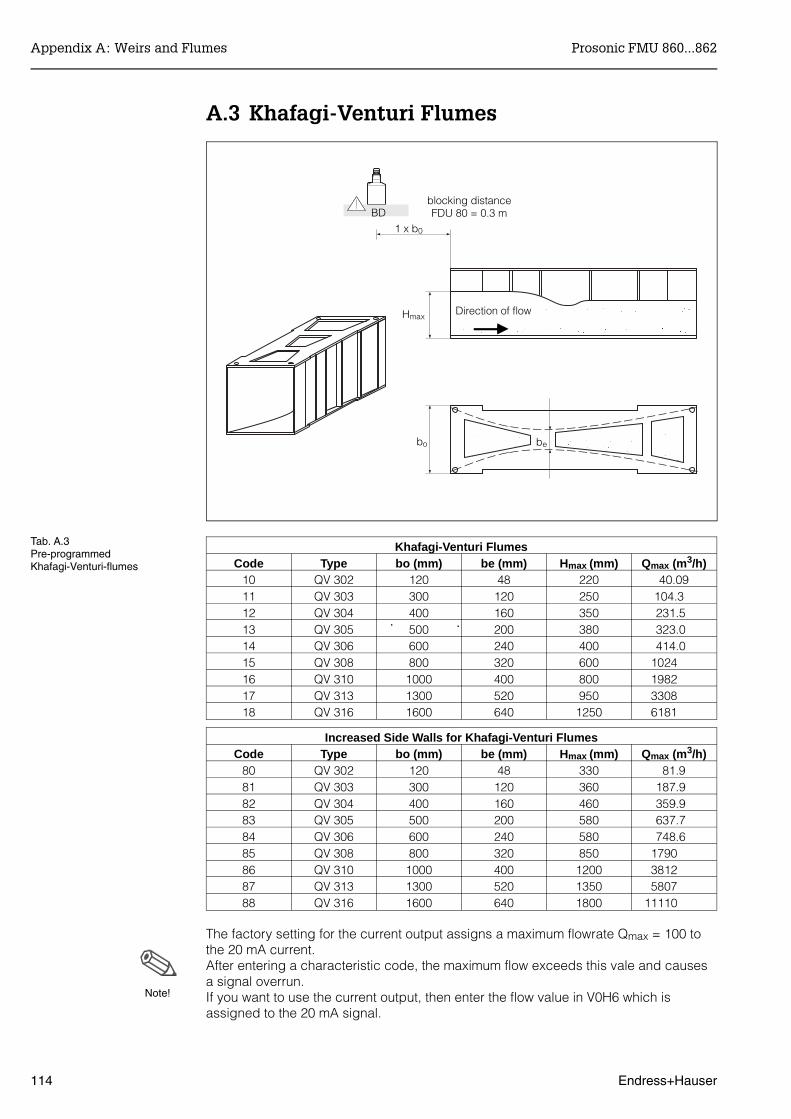
A.3 Khafagi-Venturi Flumes
Khafagi-Venturi FlumesCode Type bo (mm) be (mm) Hmax (mm) Qmax (m3/h)
10 QV 302 120 48 220 40.0911 QV 303 300 120 250 104.3 12 QV 304 400 160 350 231.5 13 QV 305 500 200 380 323.0 14 QV 306 600 240 400 414.0 15 QV 308 800 320 600 1024 16 QV 310 1000 400 800 1982 17 QV 313 1300 520 950 3308 18 QV 316 1600 640 1250 6181
Increased Side Walls for Khafagi-Venturi FlumesCode Type bo (mm) be (mm) Hmax (mm) Qmax (m3/h)
80 QV 302 120 48 330 81.981 QV 303 300 120 360 187.9 82 QV 304 400 160 460 359.9 83 QV 305 500 200 580 637.7 84 QV 306 600 240 580 748.6 85 QV 308 800 320 850 1790 86 QV 310 1000 400 1200 3812 87 QV 313 1300 520 1350 5807 88 QV 316 1600 640 1800 11110
The factory setting for the current output assigns a maximum flowrate Qmax = 100 tothe 20 mA current. After entering a characteristic code, the maximum flow exceeds this vale and causesa signal overrun. If you want to use the current output, then enter the flow value in V0H6 which isassigned to the 20 mA signal.
Note!
bebo
Hmax
1 x b0
blocking distanceFDU 80 = 0.3 m
Direction of flow
BD
Tab. A.3Pre-programmedKhafagi-Venturi-flumes
Appendix A: Weirs and Flumes Prosonic FMU 860...862
114 Endress+Hauser
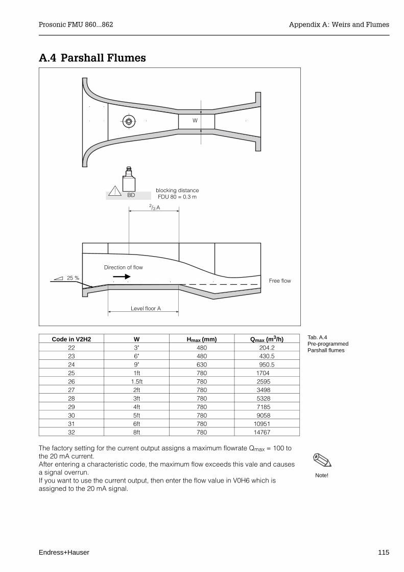
A.4 Parshall Flumes
Code in V2H2 W H max (mm) Qmax (m3/h)22 3" 480 204.223 6" 480 430.524 9" 630 950.525 1ft 780 1704 26 1.5ft 780 2595 27 2ft 780 3498 28 3ft 780 5328 29 4ft 780 7185 30 5ft 780 9058 31 6ft 780 10951 32 8ft 780 14767
The factory setting for the current output assigns a maximum flowrate Qmax = 100 tothe 20 mA current. After entering a characteristic code, the maximum flow exceeds this vale and causesa signal overrun. If you want to use the current output, then enter the flow value in V0H6 which isassigned to the 20 mA signal.
W
BDblocking distanceFDU 80 = 0.3 m
2/3 A
Level floor A
Free flow25 %
Direction of flow
Note!
Tab. A.4Pre-programmedParshall flumes
Prosonic FMU 860...862 Appendix A: Weirs and Flumes
Endress+Hauser 115

A.5 British Standard Flume
Code bmax Hmax (mm) Qmax (m3/h)40 4" 150 36.2541 7" 190 90.4442 12" 340 371.1 43 18" 480 925.7 44 30" 840 3603
The factory setting for the current output assigns a maximum flowrate Qmax = 100 tothe 20 mA current. After entering a characteristic code, the maximum flow exceeds this vale and causesa signal overrun. If you want to use the current output, then enter the flow value in V0H6 which isassigned to the 20 mA signal.
Note!
Tab. A.5Pre-programmedBritish Standard flume
approach channel
horizontal invert
exit transition
exit channel
front view(level invert)
x
Invert over length of weir x without slope(no weir with weir plate)
2 Hmax min. 3 Hmax
b
B
L ≥ 3 (B-b)
blocking distanceFDU 80 = 0.3 m
BD
Appendix A: Weirs and Flumes Prosonic FMU 860...862
116 Endress+Hauser
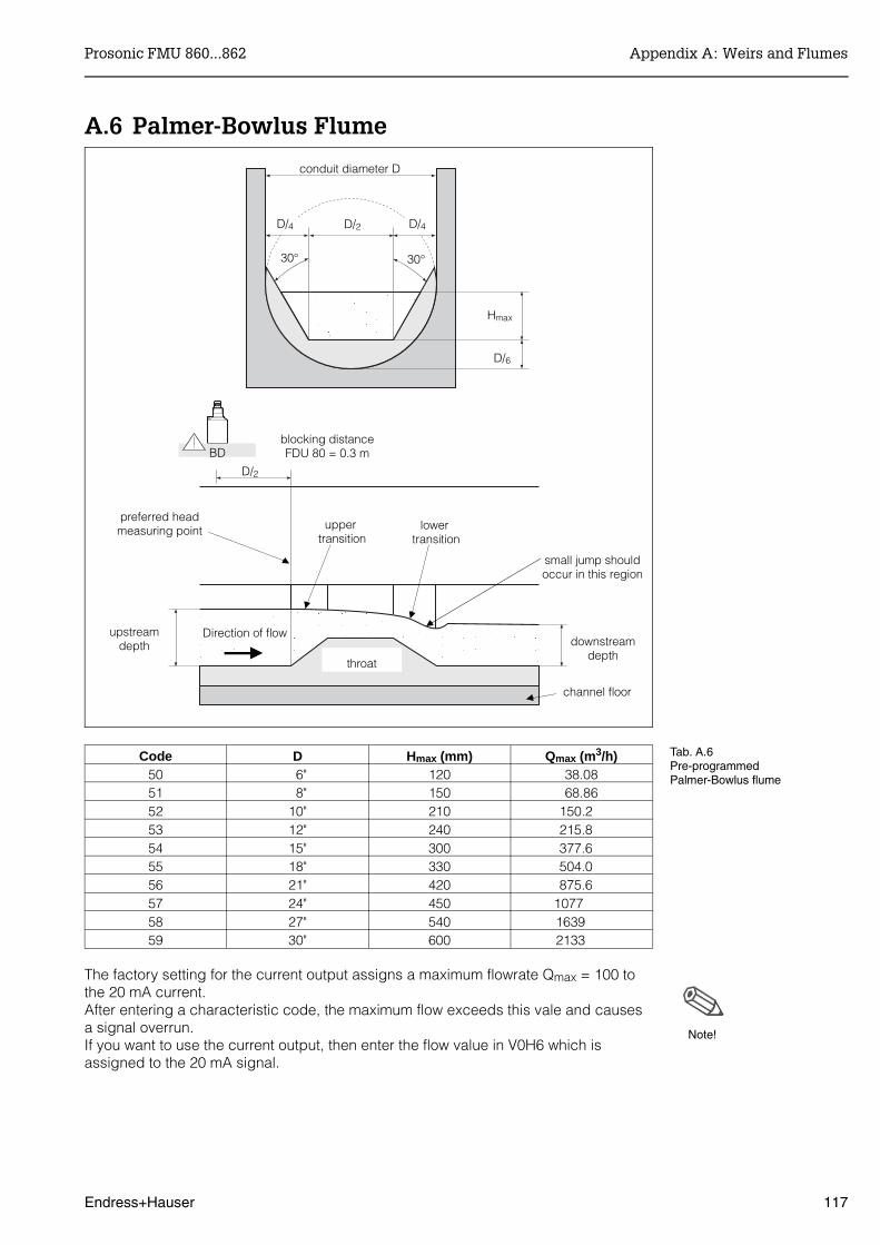
A.6 Palmer-Bowlus Flume
Code D Hmax (mm) Qmax (m3/h)50 6" 120 38.0851 8" 150 68.8652 10" 210 150.2 53 12" 240 215.8 54 15" 300 377.6 55 18" 330 504.0 56 21" 420 875.6 57 24" 450 1077 58 27" 540 1639 59 30" 600 2133
The factory setting for the current output assigns a maximum flowrate Qmax = 100 tothe 20 mA current. After entering a characteristic code, the maximum flow exceeds this vale and causesa signal overrun. If you want to use the current output, then enter the flow value in V0H6 which isassigned to the 20 mA signal.
Note!
conduit diameter D
upper transition
lower transition
small jump shouldoccur in this region
channel floor
downstreamdepth
throat
upstreamdepth
preferred headmeasuring point
Hmax
30° 30°
D/2
D/6
blocking distanceFDU 80 = 0.3 m
Direction of flow
BD
D/2
D/4 D/4
Tab. A.6Pre-programmedPalmer-Bowlus flume
Prosonic FMU 860...862 Appendix A: Weirs and Flumes
Endress+Hauser 117

A.7 Rectangular Constricted Sharp-Crested Weir
Code in V2H2 B (mm) Hmax (mm) Qmax (m3/h)60 200 120 51.1861 300 150 108.4 62 400 240 289.5 63 500 270 434.6 64 600 300 613.3 65 800 450 1492 66 1000 600 2861
The factory setting for the current output assigns a maximum flowrate Qmax = 100 tothe 20 mA current. After entering a characteristic code, the maximum flow exceeds this vale and causesa signal overrun. If you want to use the current output, then enter the flow value in V0H6 which isassigned to the 20 mA signal.
Note!
crest length B
Hmax
k k
min. 3 Hmax
45°
blocking distanceFDU 80 = 0.3 m
k = approx. 3 mm
or
weir plate
channel flow
drawdown
Direction of flow
BD
min.2 Hmax
min. 2 Hmax
Tab. A.7Pre-programmedrectangular constrictedsharp-crested weir
Appendix A: Weirs and Flumes Prosonic FMU 860...862
118 Endress+Hauser

A.8 V-Notch Sharp-Crested Weir(Triangular)
V-Notch Sharp-Crested WeirCode in V2H2 Type α Hmax (mm) Qmax (m3/h)
70 V-notch 90° 600 1385 71 V-notch 60° 600 799.872 V-notch 45° 600 574.173 V-notch 30° 600 371.2
V-Notch Sharp-Crested Weir to British Standards75 V-notch 90° 390 473.276 V-notch 1/2 90° 390 237.377 V-notch 1/4 90° 390 120.1
The factory setting for the current output assigns a maximum flowrate Qmax = 100 tothe 20 mA current. After entering a characteristic code, the maximum flow exceeds this vale and causesa signal overrun. If you want to use the current output, then enter the flow value in V0H6 which isassigned to the 20 mA signal.
Note!
Hmax
k k
min. 3 Hmax
45°
blocking distanceFDU 80 = 0.3 m
k = approx. 3 mm
or
weir plate
channel flow
drawdown
Direction of flow
BD
min.2 Hmax
min. 2 Hmax
α
Tab. A.8Pre-programmedV-Notch sharp-crested weir
Prosonic FMU 860...862 Appendix A: Weirs and Flumes
Endress+Hauser 119

A.9 Formula for Measurement in Open WeirsYour weir can be accurately calculated by using the following formula and theinformation in the following table:
Q = C (hα + γ h β)
Where: Q = flowrate in m3/hC = constanth = damming height in mmα = factorβ = factorγ = factor
Weir, flume Type Qmax.(m3/h)
α β γ C
Khafagi-Venturi flume
Increasing side wallsresult in identical α, βγ. This change only affectsHmax.
QV 302 40,09 1.500 2.500 0.0013140 0.0095299
QV 303 104,3 1.500 2.500 0.0004301 0.0238249
QV 304 231,5 1.500 2.500 0.0003225 0.0317665
QV 305 323,0 1.500 2.500 0.0002580 0.0397081
QV 306 414,0 1.500 2.500 0.0002150 0.0476497
QV 308 1024 1.500 2.500 0.0001613 0.0635329
QV 310 1982 1.500 2.500 0.0001290 0.0794162
QV 313 3308 1.500 2.500 0.0000992 0.1032410
QV 316 6181 1.500 2.500 0.0000806 0.1270659
Parshall flume 1" 15,23 1.550 1.000 0.0000000 0.0048651
2" 30,46 1.550 1.000 0.0000000 0.0097302
3" 203,8 1.547 1.000 0.0000000 0.0144964
6" 430,5 1.580 1.000 0.0000000 0.0249795
9" 950,5 1.530 1.000 0.0000000 0.0495407
1 ft 1704 1.522 1.000 0.0000000 0.0675749
1.5 ft 2595 1.538 1.000 0.0000000 0.0924837
2 ft 3498 1.550 1.000 0.0000000 0.1151107
3 ft 5328 1.566 1.000 0.0000000 0.1575984
4 ft 7185 1.578 1.000 0.0000000 0.1962034
5 ft 9058 1.587 1.000 0.0000000 0.2329573
6 ft 10951 1.595 1.000 0.0000000 0.2670383
8 ft 14767 1.607 1.000 0.0000000 0.3324357
British standard weir4" 36,25 1.500 1.000 0.0000000 0.019732
7" 90,44 1.500 1.000 0.0000000 0.034532
12" 371,2 1.500 1.000 0.0000000 0.059201
18" 925,7 1.500 1.000 0.0000000 0.088021
30" 3603 1.500 1.000 0.0000000 0.148003
Palmer-Bowlus flume 6" 38,08 0.200 2.000 0.0083313 0.3106790
8" 68,86 0.200 2.000 0.0047711 0.6255716
10" 150,2 0.200 2.000 0.0034924 0.9571182
12" 215,8 0.200 2.000 0.0022844 1.6034450
15" 377,6 0.200 2.000 0.0015814 2.5957210
18" 504,0 0.200 2.000 0.0012679 3.5431970
21" 875,6 0.200 2.000 0.0008765 5.5433280
24" 1077 0.200 2.000 0.0006771 7.6652450
27" 1639 0.200 2.000 0.0005672 9.7043720
30" 2133 0.200 2.000 0.0004475 12.9501200
Appendix A: Weirs and Flumes Prosonic FMU 860...862
120 Endress+Hauser
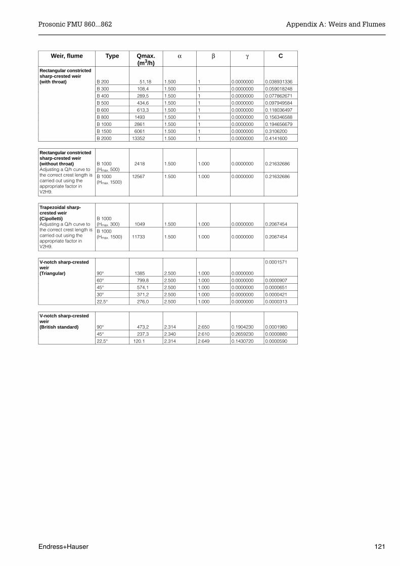
Weir, flume Type Qmax.(m3/h)
α β γ C
Rectangular constricted sharp-crested weir (with throat) B 200 51,18 1.500 1 0.0000000 0.038931336
B 300 108,4 1.500 1 0.0000000 0.059018248
B 400 289,5 1.500 1 0.0000000 0.077862671
B 500 434,6 1.500 1 0.0000000 0.097949584
B 600 613,3 1.500 1 0.0000000 0.118036497
B 800 1493 1.500 1 0.0000000 0.156346588
B 1000 2861 1.500 1 0.0000000 0.194656679
B 1500 6061 1.500 1 0.0000000 0.3106200
B 2000 13352 1.500 1 0.0000000 0.4141600
Rectangular constricted sharp-crested weir (without throat)Adjusting a Q/h curve tothe correct crest length iscarried out using theappropriate factor inV2H9.
B 1000(Hmax. 500)
2418 1.500 1.000 0.0000000 0.21632686
B 1000(Hmax. 1500)
12567 1.500 1.000 0.0000000 0.21632686
Trapezoidal sharp-crested weir(Cipolletti)Adjusting a Q/h curve tothe correct crest length iscarried out using theappropriate factor inV2H9.
B 1000(Hmax. 300) 1049 1.500 1.000 0.0000000 0.2067454
B 1000(Hmax. 1500) 11733 1.500 1.000 0.0000000 0.2067454
V-notch sharp-crestedweir(Triangular) 90° 1385 2.500 1.000 0.0000000
0.0001571
60° 799,8 2.500 1.000 0.0000000 0.0000907
45° 574,1 2.500 1.000 0.0000000 0.0000651
30° 371,2 2.500 1.000 0.0000000 0.0000421
22,5° 276,0 2.500 1.000 0.0000000 0.0000313
V-notch sharp-crestedweir (British standard) 90° 473,2 2.314 2.650 0.1904230 0.0001980
45° 237,3 2.340 2.610 0.2659230 0.0000880
22,5° 120.1 2.314 2.649 0.1430720 0.0000590
Prosonic FMU 860...862 Appendix A: Weirs and Flumes
Endress+Hauser 121
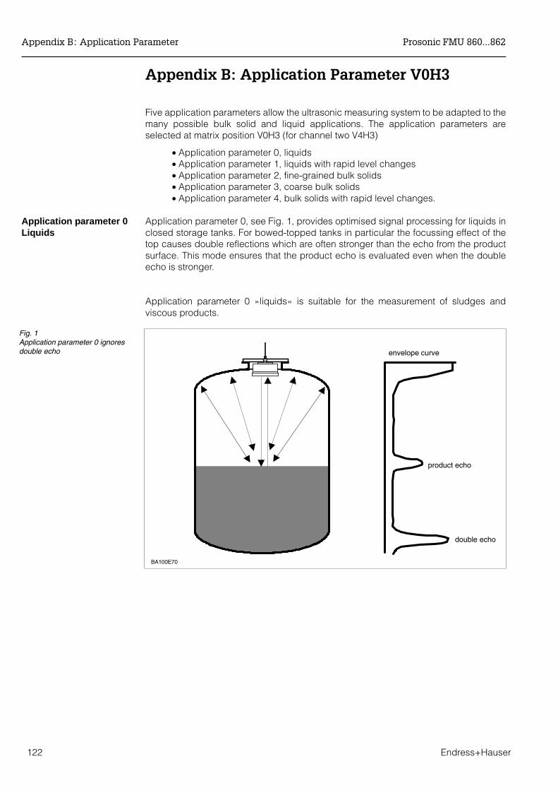
Appendix B: Application Parameter V0H3
Five application parameters allow the ultrasonic measuring system to be adapted to themany possible bulk solid and liquid applications. The application parameters areselected at matrix position V0H3 (for channel two V4H3)
• Application parameter 0, liquids• Application parameter 1, liquids with rapid level changes• Application parameter 2, fine-grained bulk solids• Application parameter 3, coarse bulk solids• Application parameter 4, bulk solids with rapid level changes.
Application parameter 0Liquids
Application parameter 0, see Fig. 1, provides optimised signal processing for liquids inclosed storage tanks. For bowed-topped tanks in particular the focussing effect of thetop causes double reflections which are often stronger than the echo from the productsurface. This mode ensures that the product echo is evaluated even when the doubleecho is stronger.
Application parameter 0 »liquids« is suitable for the measurement of sludges andviscous products.
BA100E70
envelope curve
product echo
double echo
Fig. 1Application parameter 0 ignoresdouble echo
Appendix B: Application Parameter Prosonic FMU 860...862
122 Endress+Hauser
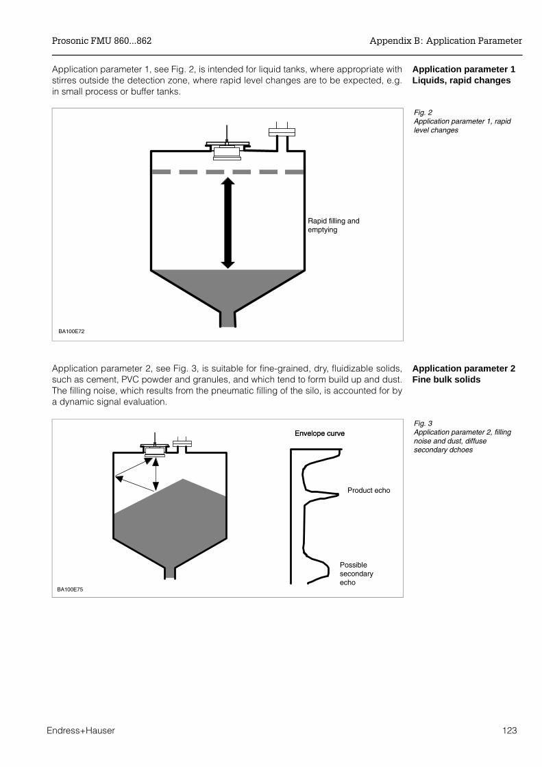
Application parameter 1Liquids, rapid changes
Application parameter 1, see Fig. 2, is intended for liquid tanks, where appropriate withstirres outside the detection zone, where rapid level changes are to be expected, e.g.in small process or buffer tanks.
Application parameter 2Fine bulk solids
Application parameter 2, see Fig. 3, is suitable for fine-grained, dry, fluidizable solids,such as cement, PVC powder and granules, and which tend to form build up and dust.The filling noise, which results from the pneumatic filling of the silo, is accounted for bya dynamic signal evaluation.
BA100E72
Rapid filling andemptying
Fig. 2Application parameter 1, rapidlevel changes
BA100E75
Envelope curveEnvelope curve
Product echo
Possiblesecondaryecho
Fig. 3Application parameter 2, fillingnoise and dust, diffusesecondary dchoes
Prosonic FMU 860...862 Appendix B: Application Parameter
Endress+Hauser 123
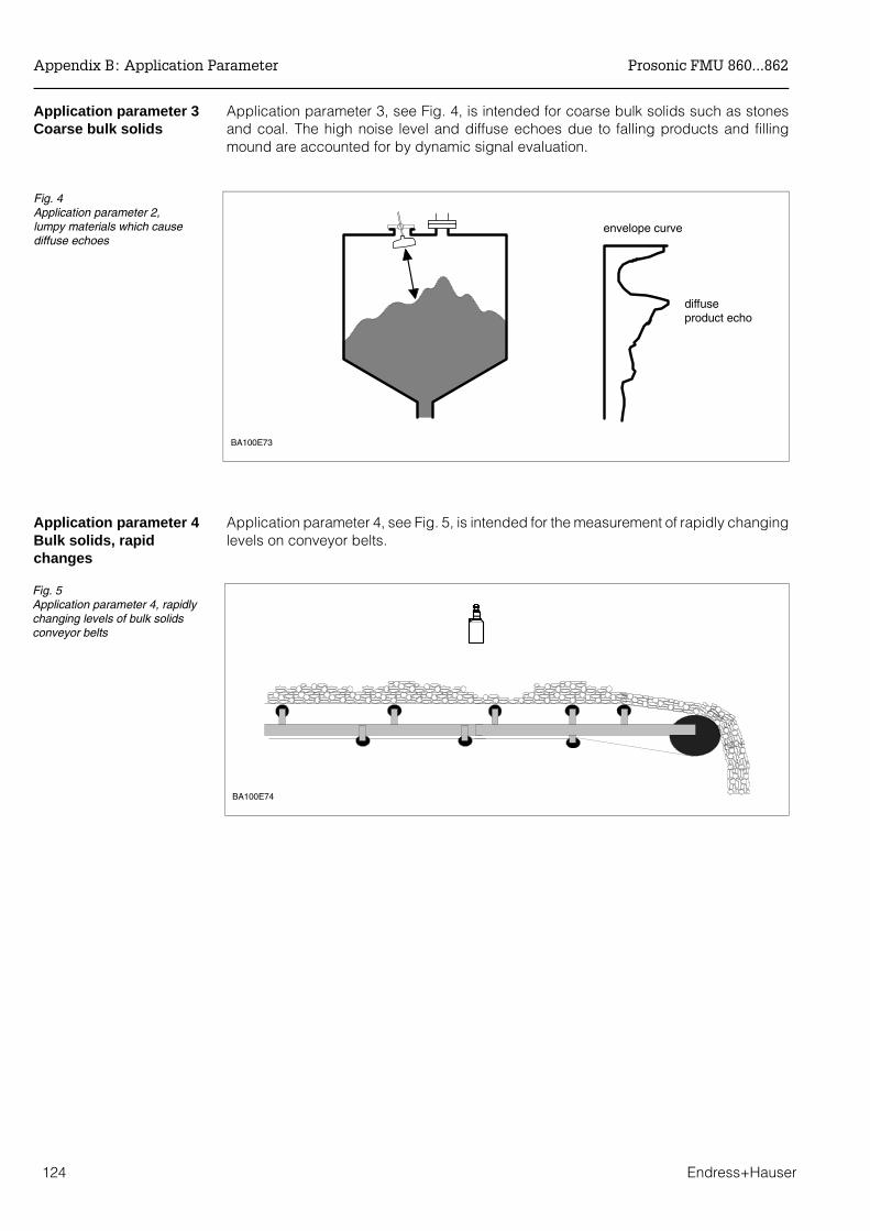
Application parameter 3Coarse bulk solids
Application parameter 3, see Fig. 4, is intended for coarse bulk solids such as stonesand coal. The high noise level and diffuse echoes due to falling products and fillingmound are accounted for by dynamic signal evaluation.
Application parameter 4Bulk solids, rapidchanges
Application parameter 4, see Fig. 5, is intended for the measurement of rapidly changinglevels on conveyor belts.
BA100E73
envelope curve
diffuseproduct echo
Fig. 4Application parameter 2,lumpy materials which causediffuse echoes
BA100E74
Fig. 5Application parameter 4, rapidlychanging levels of bulk solidsconveyor belts
Appendix B: Application Parameter Prosonic FMU 860...862
124 Endress+Hauser
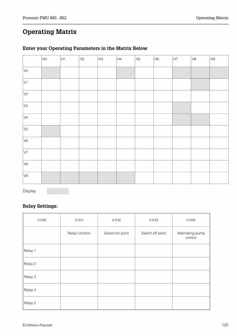
Operating Matrix
Enter your Operating Parameters in the Matrix Below
H0 H1 H2 H3 H4 H5 H6 H7 H8 H9
V0
V1
V2
V3
V4
V5
V6
V7
V8
V9
Display
Relay Settings:
V1H0 V1H1 V1H2 V1H3 V1H4
Relay function Switch-on point Switch-off point Alternating pumpcontrol
Relay 1
Relay 2
Relay 3
Relay 4
Relay 5
Prosonic FMU 860...862 Operating Matrix
Endress+Hauser 125

H0
H1
H2
H3
H4
H5
H6
H7
H8
H9
V0
Cal
ibra
tio
nC
han
nel
1M
easu
red
valu
e
Use
r un
it
Em
pty
calib
ratio
n
[10]
Met
re/F
eet
Ful
l cal
ibra
tion
[9]
Met
re/F
eet
App
licat
ion
Liq
uid
s:
0Li
quid
s fa
st: 1
Fin
e-gr
aine
d so
lids
: 2C
oars
e-gr
aine
dso
lids
: 3C
onve
yor
belt
: 4
Type
of s
enso
rF
DU
80
: 80
FD
U 8
0 F
: 80F
. . .F
DU
86
: 86
Val
ue fo
r 0/
4 m
A
[0]
Use
r un
it
Val
ue fo
r 20
mA
[100
]
Use
r un
it
Out
put d
ampi
ng
[5]
Sec
onds
Mea
sure
d di
stan
ce
Met
re/F
eet
Mea
sure
d le
vel
Met
re/F
eet
V1
Rel
ays
Rel
ay s
elec
tion
Rel
ay 1
: 1R
elay
2: 2
Rel
ay 3
: 3
Rel
ay 4
: 4R
elay
5: 5
Rel
ay fu
nctio
nL
imit
val
ue
: 0
Tend
ency
: 2A
larm
rel
ay: 8
Sw
itch-
on p
oint
[60]
–fo
r lim
it va
lue:
user
uni
t–
for
tend
ency
:%
cha
nge/
min
Sw
itch-
off p
oint
[40]
–fo
r lim
it va
lue:
user
uni
t–
for
tend
ency
:%
cha
nge/
min
Alte
rnat
ing
pum
p co
ntro
lo
ff:
0on
: 1
Sw
itch
dela
y
[1]
Sec
onds
V2
Lin
eari
sati
on
Ch
ann
el 1
Line
aris
atio
nL
inea
r:
0H
oriz
onta
l cy
linde
r: 1
Man
ual
: 3A
utom
atic
: 4C
ance
l: 5
Act
ual l
evel
[0]
Met
re/F
eet
Inpu
t vol
ume
[0]
Met
re/F
eet
Inpu
t vol
ume
[0]
Use
r un
it
Line
No.
[1]
Dia
met
er o
f ves
sel
(for
V2H
0: 1
onl
y)
[9]
Met
re/F
eet
–E
nd v
alue
Line
aris
atio
n (f
or V
2H0:
0 o
nly)
–V
olum
e of
ves
sel
(for
V2H
0: 1
onl
y)
[100
]U
ser
unit
V3
Ech
o pa
ram
eter
Cha
nnel
1R
ange
for a
utom
atic
supp
ress
ion
[0]
Met
re/F
eet
Ech
o at
tenu
atio
n
Dec
ibel
Sig
nal/n
oise
rat
io
Dec
ibel
If no
ech
oW
arn
ing
: 0
Ala
rm: 1
Saf
ety
alar
m:
–10
%:
0+
110
%: 1
Hol
d: 2
Env
elop
e cu
rve
stat
istic
s[3
]
FAC
thre
shol
d1…
100
[20]
FAC
ris
eo
ff:0
on:1
Rac
kbus
add
ress
(with
RS
485
onl
y)
V4
V5
V6
V7
Ser
vice
Ser
vice
Ser
vice
Ser
vice
Ser
vice
Ser
vice
Ser
vice
Ser
vice
Ser
vice
Ser
vice
Ser
vice
V8
Op
erat
ing
stat
us
Ope
ratin
g m
ode
Leve
l: 0
Sim
ulat
ion
: 7
Sel
ect c
urre
nt0…
20 m
A: 0
4…20
mA
: 1
4 m
A th
resh
old
off
: 0
on: 1
Sel
ect d
ista
nce
unit
Met
re:
0F
eet
: 1
Lim
it sw
itch
No
ne
: 0
NO
con
tact
Min
imum
: 1M
axim
um: 2
NC
con
tact
Min
imum
: 7M
axim
um: 8
Ext
erna
lte
mpe
ratu
re s
enso
rN
on
e:
0A
ctiv
ated
: 1
V9
Ser
vice
an
dS
imu
lati
on
Dia
gnos
tic c
ode
Last
dia
gnos
tic c
ode
E =
cle
arLa
st b
ut o
ne
diag
nost
ic c
ode
E =
cle
ar
Inst
rum
ent a
ndS
oftw
are
vers
ion
Gen
eral
Res
et33
3(f
or D
P: 1
)
Sec
urity
lock
ing
519
(for
DP
: 245
7)
Sim
ulat
ion
leve
l
Met
re/F
eet
Sim
ulat
ion
volu
me
Use
r un
it
Sim
ulat
ion
curr
ent
mA
Dis
play
fiel
d
Inpu
t fie
ld
Bo
ld =
def
ault
valu
e[te
xt in
bra
cket
s] =
defa
ult v
alue
100%
0%
»Empty«
»Full«
Matrix FMU 860

H0
H1
H2
H3
H4
H5
H6
H7
H8
H9
V0
Cal
ibra
tio
nC
han
nel
1M
easu
red
valu
e
Use
r un
it
Em
pty
calib
ratio
n
[10]
Met
re/F
eet
Ful
l cal
ibra
tion
[9]
Met
re/F
eet
App
licat
ion
Liq
uid
s:
0Li
quid
s fa
st: 1
Fin
e-gr
aine
d so
lids
: 2C
oars
e-gr
aine
dso
lids
: 3C
onve
yor
belt
: 4
Type
of s
enso
rF
DU
80
: 80
FD
U 8
0 F
: 80F
. . .F
DU
86
: 86
Val
ue fo
r 0/
4 m
A
[0]
Use
r un
it
Val
ue fo
r 20
mA
[100
]
Use
r un
it
Out
put d
ampi
ng
[5]
Sec
onds
Mea
sure
d di
stan
ce
Met
re/F
eet
Mea
sure
d le
vel
Met
re/F
eet
V1
Rel
ayR
elay
sel
ectio
nR
elay
1: 1
Rel
ay 2
: 2R
elay
3:
3R
elay
4: 4
Rel
ay 5
: 5
Rel
ay fu
nctio
nL
imit
val
ue
: 0
Tend
ency
. 2C
ount
pul
se 1
: 4C
ount
pul
se 2
: 5C
ount
pul
se 3
. 6
Inte
rval
tim
er
: 7A
larm
rel
ay: 8
Sw
itch-
on p
oint
[60]
–fo
r lim
it va
lue:
user
uni
t–
for
tend
ency
:%
cha
nge/
min
–fo
r co
unt p
ulse
:%
Qm
ax
Sw
itch-
off p
oint
[40]
–fo
r lim
it va
lue:
user
uni
t–
for
tend
ency
:%
cha
nge/
min
–fo
r co
unt p
ulse
:%
Qm
ax
Alte
rnat
ing
pum
p co
ntro
lo
ff:
0on
: 1
Cou
nt fa
ctor
C1
0…19
999
[0]
Cou
nt fa
ctor
C2
0…19
999
[0]
Cou
nt fa
ctor
C3
0…19
999
[0]
Inte
rval
tim
e
[1]
Min
utes
Sw
itch
dela
y
[1]
Sec
onds
V2
Lin
eari
sati
on
Ch
ann
el 1
Line
aris
atio
nL
inea
r:
0H
oriz
onta
lcy
linde
r: 1
Q/h
cur
ve: 2
Man
ual
: 3A
utom
atic
: 4C
ance
l: 5
Act
ual l
evel
[0]
Met
re/F
eet
Q/h
cur
ve
[1]
Inpu
t lev
el
[0]
Met
re/F
eet
Inpu
t vol
ume
[0]
Use
r un
it
Line
No.
[1]
Dia
met
er o
f ves
sel
(for
V2H
0 : 1
onl
y)
[9]
Met
re/F
eet
–E
nd v
alue
Line
aris
atio
n(f
or V
2H0:
0 o
nly)
–V
olum
e of
ves
sel
(for
V2H
0 :1
onl
y)–
Max
. flo
w[1
00]
Use
r un
it
Low
flow
cut
off
[0]
% o
f max
. flo
w
Cre
st le
ngth
Met
re/F
eet
V3
Ech
o pa
ram
eter
Cha
nnel
1R
ange
for a
utom
atic
supp
ress
ion
[0]
Met
re/F
eet
Ech
o at
tenu
atio
n
Dec
ibel
Sig
nal/n
oise
rat
io
Dec
ibel
If no
ech
oW
arn
ing
: 0
Ala
rm: 1
Saf
ety
alar
m–1
0%:
0+
110%
: 1H
old
: 2
Env
elop
e cu
rve
stat
istic
s[3
]
FAC
thre
shol
d1…
100
[20]
FAC
ris
eo
ff:
0on
: 1
Rac
kbus
add
ress
(with
RS
485
onl
y)
V4
V5
V6
V7
Ser
vice
Ser
vice
Ser
vice
Ser
vice
Ser
vice
Ser
vice
Ser
vice
Ser
vice
Ser
vice
Ser
vice
Ser
vice
V8
Op
erat
ing
stat
us
and
co
un
ter
Ope
ratin
g m
ode
Leve
l: 0
Flo
w: 2
Sim
ulat
ion
: 7
Sel
ect c
urre
nt0…
20 m
A: 0
4…20
mA
: 1
4 m
A th
resh
old
off
: 0
on: 1
Sel
ect d
ista
nce
unit
Met
re:
0F
eet
: 1
Flo
w u
nit
l/s: 0
l/min
: 1l/h
: 2m
3 /s: 3
m3 /m
in: 4
m3 /h
: 5
igps
: 6ig
pm: 7
…
Cou
nter
uni
tl
: 0hl
: 1m
3:
2ig
al: 5
usga
l: 6
bls
: 7in
ch3
: 8ft3
: 9…
Lim
it sw
itch
No
ne
: 0
NO
con
tact
M
inim
um: 1
Max
imum
: 2N
C c
onta
ctM
inim
um: 7
Max
imum
: 8
Ext
erna
lte
mpe
ratu
re s
enso
rN
on
e:
0A
ctiv
ated
: 1
Inte
rnal
cou
nter
hig
hIn
tern
al c
ount
erlo
w
V9
Ser
vice
an
dS
imu
lati
on
Dia
gnos
tic c
ode
Last
dia
gnos
tic c
ode
E =
cle
arLa
st b
ut o
nedi
agno
stic
cod
eE
= c
lear
Inst
rum
ent a
ndS
oftw
are
vers
ion
Res
et c
ount
er71
2G
ener
al r
eset
333
(for
DP
: 1)
Sec
urity
lock
ing
519
(for
DP
: 245
7)
Sim
ulat
ion
leve
l
Met
re/F
eet
Sim
ulat
ion
volu
me
Use
r un
it
Sim
ulat
ion
curr
ent
mA
Dis
play
fiel
d
Inpu
t fie
ld
Bo
ld =
def
ault
valu
e[te
xt in
bra
cket
s] =
defa
ult v
alueMatrix FMU 861
100%
0%
»Empty«
»Full«
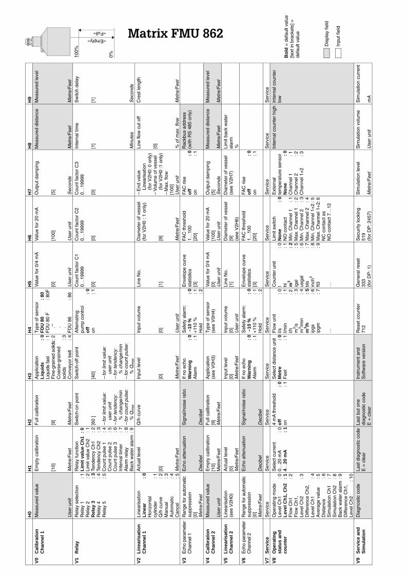
H0
H1
H2
H3
H4
H5
H6
H7
H8
H9
V0
Cal
ibra
tio
nC
han
nel
1M
easu
red
valu
e
Use
r un
it
Em
pty
calib
ratio
n
[10]
Met
re/F
eet
Ful
l cal
ibra
tion
[9]
Met
re/F
eet
App
licat
ion
Liq
uid
s:
0Li
quid
s fa
st: 1
Fin
e-gr
aine
d so
lids
: 2C
oars
e-gr
aine
dso
lids
: 3C
onve
yor
belt
: 4
Type
of s
enso
rF
DU
80
: 80
FD
U 8
0 F
: 80F
. . .F
DU
86
: 86
Val
ue fo
r 0/
4 m
A
[0]
Use
r un
it
Val
ue fo
r 20
mA
[100
]
Use
r un
it
Out
put d
ampi
ng
[5]
Sec
onds
Mea
sure
d di
stan
ce
Met
re/F
eet
Mea
sure
d le
vel
Met
re/F
eet
V1
Rel
ayR
elay
sel
ectio
nR
elay
1: 1
Rel
ay 2
: 2R
elay
3:
3R
elay
4: 4
Rel
ay 5
: 5
Rel
ay fu
nctio
nL
imit
val
ue
Ch
1:
0Li
mit
valu
e C
h2: 1
Tend
ency
Ch1
: 2Te
nden
cy C
h2: 3
Cou
nt p
ulse
1: 4
Cou
nt p
ulse
2: 5
Cou
nt p
ulse
3: 6
Inte
rval
tim
er: 7
Ala
rm r
elay
: 8B
ack
wat
er a
larm
: 9
Sw
itch-
on p
oint
[60
]
–fo
r lim
it va
lue:
user
uni
t–
for
tend
ency
:%
cha
nge/
min
–fo
r co
unt p
ulse
:%
Qm
ax
Sw
itch-
off p
oint
[40]
–fo
r lim
it va
lue:
user
uni
t–
for
tend
ency
:%
cha
nge/
min
–fo
r co
unt p
ulse
:%
Qm
ax
Alte
rnat
ing
pum
p co
ntro
lo
ff:
0on
: 1
Cou
nt fa
ctor
C1
0…19
999
[0]
Cou
nt fa
ctor
C2
0…19
999
[0]
Cou
nt fa
ctor
C3
0…19
999
[0]
Inte
rnal
tim
e
[1]
Min
utes
Sw
itch
dela
y
[1]
Sec
onds
V2
Lin
eari
sati
on
Ch
ann
el 1
Line
aris
atio
nL
inea
r:
0H
oriz
onta
l cy
linde
r: 1
Q/h
cur
ve: 2
Man
ual
: 3A
utom
atic
: 4C
ance
l: 5
Act
ual l
evel
[0]
Met
re/F
eet
Q/h
cur
veIn
put l
evel
[0]
Met
re/F
eet
Inpu
t vol
ume
[0]
Use
r un
it
Line
No.
[1]
Dia
met
er o
f ves
sel
(for
V2H
0 : 1
onl
y)
[9]
Met
re/F
eet
–E
nd v
alue
Line
aris
atio
n (f
or V
2H0:
0 o
nly)
–V
olum
e of
ves
sel
(for
V2H
0 :1
onl
y)–
Max
. flo
w[1
00]
Use
r un
it
Low
flow
cut
off
[0]
% o
f max
. flo
w
Cre
st le
ngth
Met
re/F
eet
V3
Ech
o pa
ram
eter
Cha
nnel
1R
ange
for a
utom
atic
supp
ress
ion
[0]
Met
re/F
eet
Ech
o at
tenu
atio
n
Dec
ibel
Sig
nal/n
oise
rat
io
Dec
ibel
If no
ech
oW
arn
ing
: 0
Ala
rm: 1
Saf
ety
alar
m:
–10
%:
0+
110
%: 1
Hol
d: 2
Env
elop
e cu
rve
stat
istic
s[3
]
FAC
thre
shol
d1…
100
[20]
FAC
ris
eo
ff:
0on
: 1
Rac
kbus
add
ress
(with
RS
485
onl
y)
V4
Cal
ibra
tio
n
Ch
ann
el 2
Mea
sure
d va
lue
Use
r un
it
Em
pty
calib
ratio
n[1
0]M
etre
/Fee
t
Ful
l cal
ibra
tion
[9]
Met
re/F
eet
App
licat
ion
(see
V0H
3)Ty
pe o
f sen
sor
(see
V0H
4)V
alue
for
0/4
mA
[0]
Use
r un
it
Val
ue fo
r 20
mA
[100
]U
ser
unit
Out
put d
ampi
ng[5
]S
econ
ds
Mea
sure
d di
stan
ce
Met
re/F
eet
Mea
sure
d le
vel
Met
re/F
eet
V5
Lin
eari
sati
on
Ch
ann
el 2
Line
aris
atio
n(s
ee V
2H0)
Act
ual l
evel
[0]
Met
re/F
eet
Inpu
t lev
el[0
]M
etre
/Fee
t
Inpu
t vol
ume
[0]
Use
r un
it
Line
No.
[1]
Dia
met
er o
f ves
sel
[9]
(see
V2H
6)
Dia
met
er o
f ves
sel
(see
V2H
7)Li
mit
back
wat
eral
arm
%
V6
Ech
o pa
ram
eter
Cha
nnel
2R
ange
for a
utom
atic
supp
ress
ion
[0]
Met
re/F
eet
Ech
o at
tenu
atio
n
Dec
ibel
Sig
nal/n
oise
rat
io
Dec
ibel
If no
ech
oW
arn
ing
: 0
Ala
rm: 1
Saf
ety
alar
m:
–10
%:
0+
110
%: 1
Hol
d: 2
Env
elop
e cu
rve
stat
istic
s[3
]
FAC
thre
shol
d1…
100
[20]
FAC
ris
eo
ff:
0on
: 1
V7
Ser
vice
Ser
vice
Ser
vice
Ser
vice
Ser
vice
Ser
vice
Ser
vice
Ser
vice
Ser
vice
Ser
vice
Ser
vice
V8
Op
erat
ing
st
atu
s an
dco
un
ter
Ope
ratin
g m
ode
Leve
l Ch1
: 0L
evel
Ch
1, C
h2
: 1
Flo
w C
h1: 2
Flo
w C
h1,
Leve
l Ch2
: 3D
iffer
ence
Ch2
,Le
vel C
h1: 4
Ave
rage
val
ue: 5
Dis
tanc
e: 6
Sim
ulat
ion
Ch1
: 7S
imul
atio
n C
h2: 8
Bac
k w
ater
ala
rm: 9
Diff
eren
ce C
h1,
Leve
l Ch2
: 10
Sel
ect c
urre
nt0…
20 m
A: 0
4…20
mA
: 1
4 m
A th
resh
old
off
: 0
on: 1
Sel
ect d
ista
nce
unit
Met
re:
0F
eet
: 1
Flo
w u
nit
l/s: 0
l/min
: 1l/h
: 2m
3 /s: 3
m3 /m
in: 4
m3 /h
: 5
ipgs
: 6ip
gm: 7
…
Cou
nter
uni
tl
: 0hl
: 1m
3:
2ig
al: 5
usga
l: 6
bls
: 7in
ch3
: 8ft3
: 9
…
Lim
it sw
itch
No
ne
: 0
NO
con
tact
Min
. Cha
nnel
1: 1
Max
. Cha
nnel
1: 2
Min
. Cha
nnel
2: 3
Max
. Cha
nnel
2: 4
Min
. Cha
nnel
1+
2: 5
Max
. Cha
nnel
1+
2: 6
NC
con
tact
as
NO
con
tact
7…
12
Ext
erna
lte
mpe
ratu
re s
enso
rN
on
e:
0C
hann
el 1
: 1C
hann
el 2
: 2C
hann
el 1
+2
: 3
Inte
rnal
cou
nter
hig
hIn
tern
al c
ount
erlo
w
V9
Ser
vice
an
dS
imu
lati
on
Dia
gnos
tic c
ode
Last
dia
gnos
tic c
ode
E =
cle
arLa
st b
ut o
nedi
agno
stic
cod
eE
= c
lear
Inst
rum
ent a
ndS
oftw
are
vers
ion
Res
et c
ount
er71
2G
ener
al r
eset
333
(for
DP
: 1)
Sec
urity
lock
ing
519
(for
DP
: 245
7)
Sim
ulat
ion
leve
l
Met
re/F
eet
Sim
ulat
ion
volu
me
Use
r un
it
Sim
ulat
ion
curr
ent
mA
Dis
play
fiel
d
Inpu
t fie
ld
Bo
ld =
def
ault
valu
e[te
xt in
bra
cket
s] =
defa
ult v
alueMatrix FMU 862
100%
0%
»Empty«
»Full«
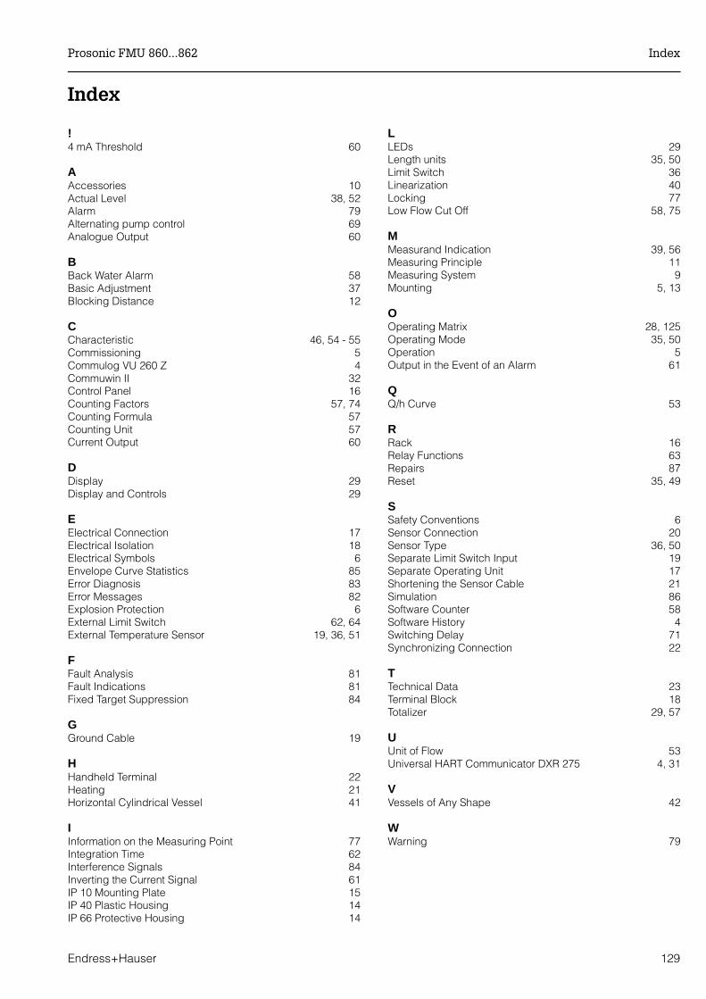
Index
!4 mA Threshold 60
AAccessories 10Actual Level 38, 52Alarm 79Alternating pump control 69Analogue Output 60
BBack Water Alarm 58Basic Adjustment 37Blocking Distance 12
CCharacteristic 46, 54 - 55Commissioning 5Commulog VU 260 Z 4Commuwin II 32Control Panel 16Counting Factors 57, 74Counting Formula 57Counting Unit 57Current Output 60
DDisplay 29Display and Controls 29
EElectrical Connection 17Electrical Isolation 18Electrical Symbols 6Envelope Curve Statistics 85Error Diagnosis 83Error Messages 82Explosion Protection 6External Limit Switch 62, 64External Temperature Sensor 19, 36, 51
FFault Analysis 81Fault Indications 81Fixed Target Suppression 84
GGround Cable 19
HHandheld Terminal 22Heating 21Horizontal Cylindrical Vessel 41
IInformation on the Measuring Point 77Integration Time 62Interference Signals 84Inverting the Current Signal 61IP 10 Mounting Plate 15IP 40 Plastic Housing 14IP 66 Protective Housing 14
LLEDs 29Length units 35, 50Limit Switch 36Linearization 40Locking 77Low Flow Cut Off 58, 75
MMeasurand Indication 39, 56Measuring Principle 11Measuring System 9Mounting 5, 13
OOperating Matrix 28, 125Operating Mode 35, 50Operation 5Output in the Event of an Alarm 61
QQ/h Curve 53
RRack 16Relay Functions 63Repairs 87Reset 35, 49
SSafety Conventions 6Sensor Connection 20Sensor Type 36, 50Separate Limit Switch Input 19Separate Operating Unit 17Shortening the Sensor Cable 21Simulation 86Software Counter 58Software History 4Switching Delay 71Synchronizing Connection 22
TTechnical Data 23Terminal Block 18Totalizer 29, 57
UUnit of Flow 53Universal HART Communicator DXR 275 4, 31
VVessels of Any Shape 42
WWarning 79
Prosonic FMU 860...862 Index
Endress+Hauser 129
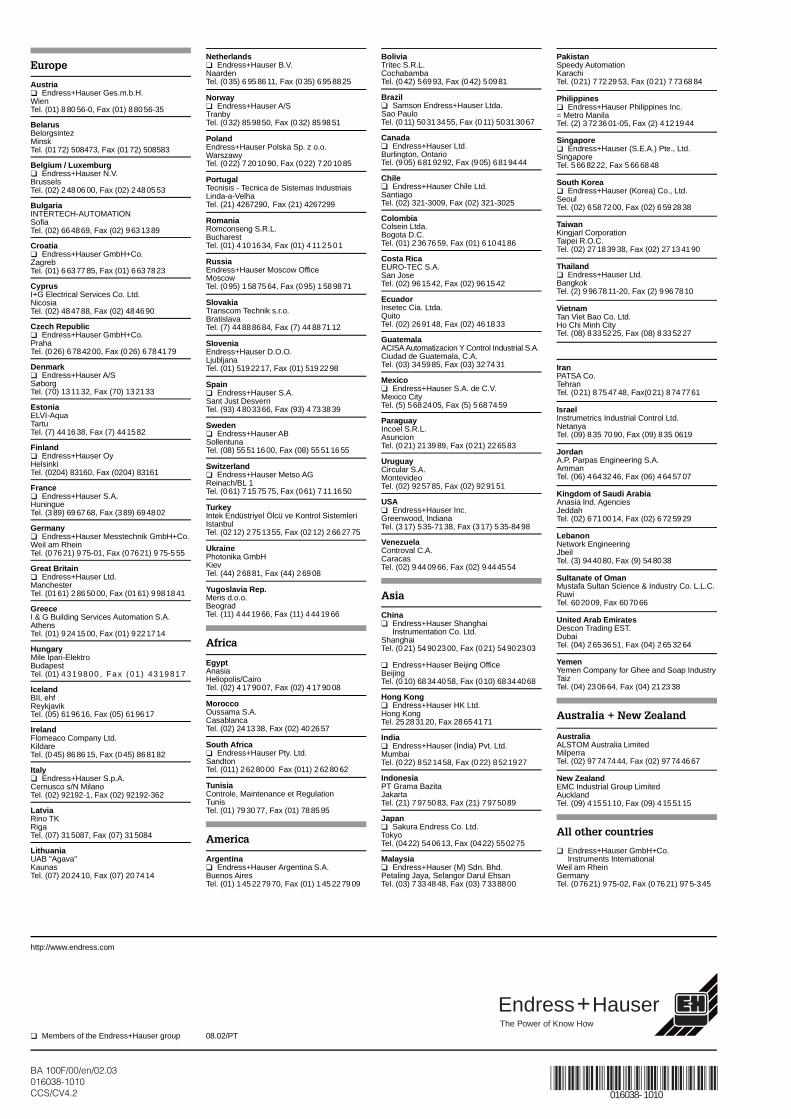
Europe
Austria Endress+Hauser Ges.m.b.H.WienTel. (01) 8 80 56-0, Fax (01) 88056-35
BelarusBelorgsintezMinskTel. (0172) 508473, Fax (0172) 508583
Belgium / Luxemburg Endress+Hauser N.V.BrusselsTel. (02) 2 48 06 00, Fax (02) 2480553
BulgariaINTERTECH-AUTOMATIONSofiaTel. (02) 664869, Fax (02) 9 63 13 89
Croatia Endress+Hauser GmbH+Co.ZagrebTel. (01) 6 63 77 85, Fax (01) 6637823
CyprusI+G Electrical Services Co. Ltd.NicosiaTel. (02) 484788, Fax (02) 484690
Czech Republic Endress+Hauser GmbH+Co.PrahaTel. (0 26) 6784200, Fax (0 26) 6784179
Denmark Endress+Hauser A/SSøborgTel. (70) 131132, Fax (70) 132133
EstoniaELVI-AquaTartuTel. (7) 44 16 38, Fax (7) 441582
Finland Endress+Hauser OyHelsinkiTel. (0204) 83160, Fax (0204) 83161
France Endress+Hauser S.A.HuningueTel. (3 89) 69 67 68, Fax (389) 694802
Germany Endress+Hauser Messtechnik GmbH+Co.Weil am RheinTel. (0 76 21) 975-01, Fax (07621) 9 75-5 55
Great Britain Endress+Hauser Ltd.ManchesterTel. (0161) 2 86 50 00, Fax (01 61) 9981841
GreeceI & G Building Services Automation S.A.AthensTel. (01) 9 24 15 00, Fax (01) 9221714
HungaryMile Ipari-ElektroBudapestTel. (01) 4 31 98 00 , Fa x ( 01 ) 43 19 81 7
IcelandBIL ehfReykjavikTel. (05) 619616, Fax (05) 619617
IrelandFlomeaco Company Ltd.KildareTel. (0 45) 86 86 15, Fax (045) 868182
Italy Endress+Hauser S.p.A.Cernusco s/N MilanoTel. (02) 92192-1, Fax (02) 92192-362
LatviaRino TKRigaTel. (07) 315087, Fax (07) 315084
LithuaniaUAB "Agava"KaunasTel. (07) 202410, Fax (07) 207414
Netherlands Endress+Hauser B.V.NaardenTel. (035) 6 95 86 11, Fax (0 35) 6958825
Norway Endress+Hauser A/STranbyTel. (032) 859850, Fax (0 32) 85 98 51
PolandEndress+Hauser Polska Sp. z o.o.WarszawyTel. (022) 7 20 10 90, Fax (022) 7 20 10 85
PortugalTecnisis - Tecnica de Sistemas IndustriaisLinda-a-VelhaTel. (21) 4267290, Fax (21) 4267299
RomaniaRomconseng S.R.L.BucharestTel. (01) 4101634, Fax (01) 4 11 25 01
RussiaEndress+Hauser Moscow OfficeMoscowTel. (095) 1 58 75 64, Fax (095) 1 58 98 71
SlovakiaTranscom Technik s.r.o.BratislavaTel. (7) 44888684, Fax (7) 44 88 71 12
SloveniaEndress+Hauser D.O.O.LjubljanaTel. (01) 5192217, Fax (01) 519 22 98
Spain Endress+Hauser S.A.Sant Just DesvernTel. (93) 4803366, Fax (93) 4 73 38 39
Sweden Endress+Hauser ABSollentunaTel. (08) 55 51 16 00, Fax (08) 55 51 16 55
Switzerland Endress+Hauser Metso AGReinach/BL 1Tel. (061) 7 15 75 75, Fax (061) 7 11 16 50
TurkeyIntek Endüstriyel Ölcü ve Kontrol SistemleriIstanbulTel. (02 12) 2751355, Fax (0212) 2 66 27 75
UkrainePhotonika GmbHKievTel. (44) 26881, Fax (44) 2 69 08
Yugoslavia Rep.Meris d.o.o.BeogradTel. (11) 4 44 19 66, Fax (11) 4 44 19 66
Africa
EgyptAnasiaHeliopolis/CairoTel. (02) 4179007, Fax (02) 4 17 90 08
MoroccoOussama S.A.CasablancaTel. (02) 24 13 38, Fax (02) 40 26 57
South Africa Endress+Hauser Pty. Ltd.SandtonTel. (011) 2628000 Fax (011) 2 62 80 62
TunisiaControle, Maintenance et RegulationTunisTel. (01) 79 30 77, Fax (01) 78 85 95
America
Argentina Endress+Hauser Argentina S.A.Buenos AiresTel. (01) 145227970, Fax (01) 1 45 22 79 09
BoliviaTritec S.R.L.CochabambaTel. (0 42) 56993, Fax (0 42) 50981
Brazil Samson Endress+Hauser Ltda.Sao PauloTel. (0 11) 50313455, Fax (0 11) 50313067
Canada Endress+Hauser Ltd.Burlington, OntarioTel. (9 05) 6819292, Fax (9 05) 6819444
Chile Endress+Hauser Chile Ltd.SantiagoTel. (02) 321-3009, Fax (02) 321-3025
ColombiaColsein Ltda.Bogota D.C.Tel. (01) 2 36 76 59, Fax (01) 6104186
Costa RicaEURO-TEC S.A.San JoseTel. (02) 961542, Fax (02) 961542
EcuadorInsetec Cia. Ltda.QuitoTel. (02) 269148, Fax (02) 461833
GuatemalaACISA Automatizacion Y Control Industrial S.A.Ciudad de Guatemala, C.A.Tel. (03) 345985, Fax (03) 327431
Mexico Endress+Hauser S.A. de C.V.Mexico CityTel. (5) 5682405, Fax (5) 5687459
ParaguayIncoel S.R.L.AsuncionTel. (0 21) 21 39 89, Fax (021) 226583
UruguayCircular S.A.MontevideoTel. (02) 925785, Fax (02) 929151
USA Endress+Hauser Inc.Greenwood, IndianaTel. (3 17) 535-71 38, Fax (317) 5 35-8498
VenezuelaControval C.A.CaracasTel. (02) 9 44 09 66, Fax (02) 9444554
Asia
China Endress+Hauser Shanghai
Instrumentation Co. Ltd.ShanghaiTel. (0 21) 54 90 23 00, Fax (021) 54902303
Endress+Hauser Beijing OfficeBeijingTel. (0 10) 68 34 40 58, Fax (010) 68344068
Hong Kong Endress+Hauser HK Ltd.Hong KongTel. 25 28 31 20, Fax 28654171
India Endress+Hauser (India) Pvt. Ltd.MumbaiTel. (0 22) 8521458, Fax (0 22) 8521927
IndonesiaPT Grama BazitaJakartaTel. (21) 7 97 50 83, Fax (21) 7975089
Japan Sakura Endress Co. Ltd.TokyoTel. (0422) 540613, Fax (0422) 550275
Malaysia Endress+Hauser (M) Sdn. Bhd.Petaling Jaya, Selangor Darul EhsanTel. (03) 7 33 48 48, Fax (03) 7338800
PakistanSpeedy AutomationKarachiTel. (021) 7 72 29 53, Fax (021) 7 73 68 84
Philippines Endress+Hauser Philippines Inc.= Metro ManilaTel. (2) 3 72 36 01-05, Fax (2) 4121944
Singapore Endress+Hauser (S.E.A.) Pte., Ltd.SingaporeTel. 5 66 82 22, Fax 5 66 68 48
South Korea Endress+Hauser (Korea) Co., Ltd.SeoulTel. (02) 6587200, Fax (02) 6 59 28 38
TaiwanKingjarl CorporationTaipei R.O.C.Tel. (02) 27 18 39 38, Fax (02) 27 13 41 90
Thailand Endress+Hauser Ltd.BangkokTel. (2) 9 96 78 11-20, Fax (2) 9 96 78 10
VietnamTan Viet Bao Co. Ltd.Ho Chi Minh CityTel. (08) 8335225, Fax (08) 8 33 52 27
IranPATSA Co.TehranTel. (021) 8 75 47 48, Fax(0 21) 8747761
IsraelInstrumetrics Industrial Control Ltd.NetanyaTel. (09) 835 70 90, Fax (09) 835 0619
JordanA.P. Parpas Engineering S.A.AmmanTel. (06) 4643246, Fax (06) 4 64 57 07
Kingdom of Saudi ArabiaAnasia Ind. AgenciesJeddahTel. (02) 6710014, Fax (02) 6 72 59 29
LebanonNetwork EngineeringJbeilTel. (3) 944080, Fax (9) 54 80 38
Sultanate of OmanMustafa Sultan Science & Industry Co. L.L.C.RuwiTel. 602009, Fax 60 70 66
United Arab EmiratesDescon Trading EST.DubaiTel. (04) 2653651, Fax (04) 2 65 32 64
YemenYemen Company for Ghee and Soap IndustryTaizTel. (04) 23 06 64, Fax (04) 21 23 38
Australia + New Zealand
AustraliaALSTOM Australia LimitedMilperraTel. (02) 97 74 74 44, Fax (02) 97 74 46 67
New ZealandEMC Industrial Group LimitedAucklandTel. (09) 4155110, Fax (09) 4 15 51 15
All other countries
Endress+Hauser GmbH+Co.Instruments International
Weil am RheinGermanyTel. (07621) 9 75-02, Fax (0 76 21) 97 5-345
BA 100F/00/en/02.03016038-1010CCS/CV4.2 016038- 1010
08.02/PT Members of the Endress+Hauser group
Hauser+EndressThe Power of Know How
http://www.endress.com


