MT-1 MANUAL TRANSMISSION C TRANSMISSION/TRANSAXLE CONTENTS D E F G H I J K L M SECTION MT A B MT Revision; 2004 April 2003 G35 Coupe MANUAL TRANSMISSION PRECAUTIONS ......................................................... 2 Caution .................................................................... 2 Precautions for Battery Service ............................... 2 PREPARATION .......................................................... 3 Special Service Tools .............................................. 3 Commercial Service Tools ....................................... 6 NOISE, VIBRATION AND HARSHNESS (NVH) TROUBLESHOOTING ............................................... 7 NVH Troubleshooting Chart .................................... 7 MANUAL TRANSMISSION .................................. 7 DESCRIPTION ........................................................... 8 Cross-Sectional View .............................................. 8 DOUBLE-CONE SYNCHRONIZER ..................... 8 TRIPLE-CONE SYNCHRONIZER ....................... 9 M/T OIL .................................................................... 10 Replacement ......................................................... 10 DRAINING .......................................................... 10 FILLING .............................................................. 10 Checking ............................................................... 10 OIL LEAKAGE AND OIL LEVEL ........................ 10 REAR OIL SEAL ...................................................... 11 Removal and Installation ........................................ 11 REMOVAL ........................................................... 11 INSTALLATION ................................................... 11 POSITION SWITCH ................................................. 12 Checking ............................................................... 12 COMPONENT LOCATION ................................. 12 BACK-UP LAMP SWITCH ................................. 12 NEUTRAL POSITION SWITCH ......................... 12 SHIFT CONTROL .................................................... 13 Removal and Installation ....................................... 13 REMOVAL .......................................................... 13 INSTALLATION .................................................. 15 INSPECTION AFTER INSTALLATION ............... 17 AIR BREATHER HOSE ........................................... 18 Removal and Installation ....................................... 18 TRANSMISSION ASSEMBLY ................................. 19 Removal and Installation from Vehicle .................. 19 REMOVAL .......................................................... 19 INSTALLATION .................................................. 21 Component Parts Drawing .................................... 22 CASE COMPONENTS ....................................... 22 GEAR COMPONENTS ...................................... 23 SHIFT CONTROL COMPONENTS .................... 25 Disassembly and Assembly ................................... 27 DISASSEMBLY .................................................. 27 INSPECTION AFTER DISASSEMBLY ............... 38 ASSEMBLY ........................................................ 43 SERVICE DATA AND SPECIFICATIONS (SDS) ..... 61 General Specifications ........................................... 61 End Play ................................................................ 61 Snap Rings ............................................................ 62 Baulk Ring Clearance ............................................ 63
Transcript
MT-1
MANUAL TRANSMISSION
C TRANSMISSION/TRANSAXLE
CONTENTS
D
E
F
G
H
I
J
K
L
M
SECTION MTA
B
MT
Revision; 2004 April 2003 G35 Coupe
MANUAL TRANSMISSION
PRECAUTIONS .......................................................... 2Caution ..................................................................... 2Precautions for Battery Service ................................ 2
PREPARATION ........................................................... 3Special Service Tools ............................................... 3Commercial Service Tools ........................................ 6
NOISE, VIBRATION AND HARSHNESS (NVH) TROUBLESHOOTING ................................................ 7
Component Parts Drawing ..................................... 22CASE COMPONENTS ........................................ 22GEAR COMPONENTS ....................................... 23SHIFT CONTROL COMPONENTS ..................... 25
Disassembly and Assembly .................................... 27DISASSEMBLY ................................................... 27INSPECTION AFTER DISASSEMBLY ................ 38ASSEMBLY ......................................................... 43
SERVICE DATA AND SPECIFICATIONS (SDS) ...... 61General Specifications ............................................ 61End Play ................................................................. 61Snap Rings ............................................................. 62Baulk Ring Clearance ............................................. 63
MT-2
PRECAUTIONS
Revision; 2004 April 2003 G35 Coupe
PRECAUTIONS PFP:00001
Caution ACS006E0
● Do not reuse transmission oil, once it has been drained.● Check oil level or replace oil with vehicle on level ground.● During removal or installation, keep inside of transmission clear of dust or dirt.● Check for the correct installation status prior to removal or disassembly. If mating marks are required, be
certain they do not interfere with the function of the parts they are applied to.● In principle, tighten bolts or nuts gradually in several steps working diagonally from inside to outside. If
tightening sequence is specified, observe it.● Be careful not to damage sliding surfaces and mating surfaces.
Precautions for Battery Service ACS006E1
Before disconnecting the battery, lower both the driver and passenger windows. This will prevent any interfer-ence between the window edge and the vehicle when the door is opened/closed. During normal operation, thewindow slightly raises and lowers automatically to prevent any window to vehicle interference. The automaticwindow function will not work with the battery disconnected.
PREPARATION
MT-3
D
E
F
G
H
I
J
K
L
M
A
B
MT
Revision; 2004 April 2003 G35 Coupe
PREPARATION PFP:00002
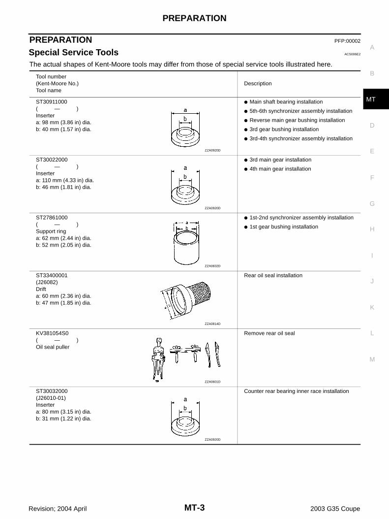
Special Service Tools ACS006E2
The actual shapes of Kent-Moore tools may differ from those of special service tools illustrated here.
Tool number(Kent-Moore No.)Tool name
Description
ST30911000( — )Insertera: 98 mm (3.86 in) dia.b: 40 mm (1.57 in) dia.
● Main shaft bearing installation
● 5th-6th synchronizer assembly installation
● Reverse main gear bushing installation
● 3rd gear bushing installation
● 3rd-4th synchronizer assembly installation
ST30022000( — )Insertera: 110 mm (4.33 in) dia.b: 46 mm (1.81 in) dia.
● 3rd main gear installation
● 4th main gear installation
ST27861000( — )Support ringa: 62 mm (2.44 in) dia.b: 52 mm (2.05 in) dia.
● 1st-2nd synchronizer assembly installation
● 1st gear bushing installation
ST33400001(J26082)Drifta: 60 mm (2.36 in) dia.b: 47 mm (1.85 in) dia.
Rear oil seal installation
KV381054S0( — )Oil seal puller
Remove rear oil seal
ST30032000(J26010-01)Insertera: 80 mm (3.15 in) dia.b: 31 mm (1.22 in) dia.
Counter rear bearing inner race installation
ZZA0920D
ZZA0920D
ZZA0832D
ZZA0814D
ZZA0601D
ZZA0920D
MT-4
PREPARATION
Revision; 2004 April 2003 G35 Coupe
KV32102700( — )Drifta: 48 mm (1.89 in) dia.b: 41 mm (1.61 in) dia.
Main drive gear bearing installation
ST23860000( — )Drifta: 38 mm (1.50 in) dia.b: 33 mm (1.30 in) dia.
Reverse counter gear installation
ST01530000( — )Drifta: 50 mm (1.97 in) dia.b: 41 mm (1.61 in) dia.
Reverse synchronizer assembly installation
ST35291000( — )Drifta: 40 mm (1.57 in) dia.b: 29.5 mm (1.161 in) dia.c: 22.5 mm (0.886 in) dia.
Striking rod oil seal installation
KV40100630(J26092)Insertera: 67 mm (2.64 in) dia.b: 38 mm (1.50 in) dia.
4th counter gear thrust washer installation
KV38102100(J25803-01)Drifta: 44 mm (2.36 in) dia.b: 28 mm (1.10 in) dia.
Front cover oil seal installation
KV32103300(J46529)Press plate
Reverse synchronizer assembly installation
Tool number(Kent-Moore No.)Tool name
Description
ZZA0534D
ZZA0534D
ZZA0534D
SCIA1575E
ZZA0920D
NT084
PCIB0165J
PREPARATION
MT-5
D
E
F
G
H
I
J
K
L
M
A
B
MT
Revision; 2004 April 2003 G35 Coupe
ST30031000(J22912-01)Puller
Inner baulk ring support
ST224490000( — )Adapter setting plate
Hold adapter plate
Tool number(Kent-Moore No.)Tool name
Description
ZZC0499D
ZZC0465D
MT-6
PREPARATION
Revision; 2004 April 2003 G35 Coupe
Commercial Service Tools ACS006E3
Tool name Description
Puller Each bearing, gear and bushing removal
Pin punchTip diameter: 6.0 mm (0.24 in) dia.
Each retaining pin removaland installation
Power tool Loosening bolts and nuts
Puller ● Reverse synchronizer assembly removal
● Reverse counter gear removal
● Reverse main gear removal
ZZB0823D
ZZA0815D
PBIC0190E
NT077
NOISE, VIBRATION AND HARSHNESS (NVH) TROUBLESHOOTING
MT-7
D
E
F
G
H
I
J
K
L
M
A
B
MT
Revision; 2004 April 2003 G35 Coupe
NOISE, VIBRATION AND HARSHNESS (NVH) TROUBLESHOOTING PFP:00003
NVH Troubleshooting Chart ACS006E4
Use the chart below to help you find the cause of the symptom. The numbers indicate the order of the inspec-tion. If necessary, repair or replace these parts.
MANUAL TRANSMISSION
Reference page
MT-
10
MT-
10
MT-
10
MT-
22
MT-
22
MT-
13
MT-
25
MT-
25
MT-
23
MT-
23
MT-
23
MT-
23
SUSPECTED PARTS(Possible cause)
OIL
(O
il le
vel i
s lo
w.)
OIL
(W
rong
oil.
)
OIL
(O
il le
vel i
s hi
gh.)
GA
SK
ET
(D
amag
ed)
OIL
SE
AL
(Wor
n or
dam
aged
)
SH
IFT
CO
NT
RO
L LI
NK
AG
E (
Wor
n)
CH
EC
K P
LUG
RE
TU
RN
SP
RIN
G A
ND
CH
EC
K B
ALL
(W
orn
or d
amag
ed)
SH
IFT
FO
RK
(W
orn)
GE
AR
(W
orn
or d
amag
ed)
BE
AR
ING
(W
orn
or d
amag
ed)
BA
ULK
RIN
G (
Wor
n or
dam
aged
)
INS
ER
T S
PR
ING
(D
amag
ed)
Symptoms
Noise 1 2 3 3
Oil leakage 3 1 2 2
Hard to shift or will not shift 1 1 2 2 2
Jumps out of gear 1 1 2 2
MT-8
DESCRIPTION
Revision; 2004 April 2003 G35 Coupe
DESCRIPTION PFP:00000
Cross-Sectional View ACS006E5
DOUBLE-CONE SYNCHRONIZERThe 1st, 3rd and 4th gears are equipped with a double-cone synchronizer to reduce the operating force of theshift lever as shown.
1. Front cover 2. Main drive gear 3. 5th-6th synchronizer hub
4. 5th-6th coupling sleeve 5. Transmission case 6. 6th main gear
TRIPLE-CONE SYNCHRONIZER The 2nd gear is equipped with a triple-cone synchronizer to reduce the operating force of the shift lever asshown.
PCIB0594E
MT-10
M/T OIL
Revision; 2004 April 2003 G35 Coupe
M/T OIL PFP:KLD20
Replacement ACS006E6
DRAINING1. Start the engine and warm up the transmission unit sufficiently.2. After stopping engine, remove filler plug and drain plug to drain oil.3. Replace gasket on drain plug with new one. Screw drain plug into transmission case, and tighten to the
specified torque. Refer to MT-22, "CASE COMPONENTS" .CAUTION:Do not reuse gasket.
FILLING1. Fill new oil into the transmission to the level of the filler plug mounting hole.
2. Replace gasket on filler plug with new one. Screw filler plug into transmission case, and tighten to thespecified torque. Refer to MT-22, "CASE COMPONENTS" .CAUTION:Do not reuse gasket.
Checking ACS006E7
OIL LEAKAGE AND OIL LEVEL● Check if oil is leaking from transmission or around it.● Check oil level from filler hole as shown in the figure.
CAUTION:Never start engine while checking oil level.
● When screwing in filler plug with a new gasket, first screw intothe transmission by hand, then tighten to the specified torque.Refer to MT-22, "CASE COMPONENTS" . CAUTION:Do not reuse gasket.
Oil grade: API GL-4Viscosity: Refer to MA-9, "Fluids and Lubricants" .Oil capacity: Approx. 2.9 (3-1/8 US qt, 2-1/2 lmp qt)
PCIB0268E
REAR OIL SEAL
MT-11
D
E
F
G
H
I
J
K
L
M
A
B
MT
Revision; 2004 April 2003 G35 Coupe
REAR OIL SEAL PFP:33140
Removal and Installation ACS006E8
REMOVAL1. Remove propeller shaft. Refer to PR-4, "Removal and Installation" .2. Remove rear oil seal using oil seal puller.
INSTALLATION1. Apply multi-purpose grease to rear oil seal lip. Drive in rear oil
seal until the edge is approximately 1.2 - 2.2 mm (0.047 - 0.087in) above the boss edge using drift.
CAUTION:● Do not reuse rear oil seal.● When installing, do not tilt oil seal.
2. Install propeller shaft. Refer to PR-4, "Removal and Installation" .CAUTION:● If lubricant leak has occurred during the repair work, check oil level after finishing work. Refer
to MT-10, "Checking" .
Tool number : KV381054S0 ( — )
PCIB0194E
Tool number : ST33400001 (J26082)
PCIB0267E
MT-12
POSITION SWITCH
Revision; 2004 April 2003 G35 Coupe
POSITION SWITCH PFP:32005
Checking ACS006E9
COMPONENT LOCATION
BACK-UP LAMP SWITCH● Check continuity.
NEUTRAL POSITION SWITCH● Check continuity.
PCIB0622E
Gear position Continuity
Reverse Yes
Except reverse No
SCIA0645E
Gear position Continuity
Neutral Yes
Except neutral No
SCIA0645E
SHIFT CONTROL
MT-13
D
E
F
G
H
I
J
K
L
M
A
B
MT
Revision; 2004 April 2003 G35 Coupe
SHIFT CONTROL PFP:34103
Removal and Installation ACS006EA
REMOVAL1. Remove shift knob with the following procedure.a. Release metal clips on console boots from center console. Refer
to IP-11, "Removal and Installation" .
1. Insulator 2. Seat 3. Control lever
4. Control lever spring 5. Guide plate 6. Control lever boot
7. Hole cover 8. Shift knob
PCIB0689E
PCIB0435E
MT-14
SHIFT CONTROL
Revision; 2004 April 2003 G35 Coupe
b. Lift console boot, and push down hole cover. Set water pumpplier or a suitable tool to control lever.CAUTION:Put waste cloth between water pump plier and control leverassembly to avoid damaging control lever.
c. Set monkey wrench to shift knob.CAUTION:Put waste cloth between shift knob and monkey wrench toavoid damaging shift knob.
d. Keeping control lever in place with water pump plier, turn mon-key wrench counterclockwise to loosen shift knob.NOTE:Remove shift knob from control lever keeping water pump plierin place because a certain power to turn shift knob is still neces-sary even after adhesive is peeled.
2. Remove console boot. Refer to IP-11, "Removal and Installa-tion" .
3. Release the boot, remove control rod mounting bolt, and sepa-rate control lever and control rod.
4. Remove the mounting bolts to remove hole cover.5. Remove the control lever boot.
SCIA2607E
SCIA2608E
SCIA2609J
SCIA1671E
SCIA1511E
SHIFT CONTROL
MT-15
D
E
F
G
H
I
J
K
L
M
A
B
MT
Revision; 2004 April 2003 G35 Coupe
6. Remove guide plate mounting bolts, and then remove controllever and control lever spring from shift lever housing.
INSTALLATION1. Set control lever and control lever spring in the vehicle and loosely mount guide plate.2. After installing control lever in control rod, tighten bolts to the
specified torque. Refer to MT-25, "SHIFT CONTROL COMPO-NENTS" .
3. After shifting control lever into 6th gear, push it toward reversegear (to the right) until it comes to a stop.
4. At the point where the control lever assembly stops, bring theguide plate closer until guide plate stopper contacts control leverassembly claw, and then loosely tighten mounting bolt A.
SCIA1365E
SCIA2561J
SCIA1665E
MT-16
SHIFT CONTROL
Revision; 2004 April 2003 G35 Coupe
5. After shifting control lever into 5th gear, push it toward reversegear (to the right) until it comes to a stop.
6. At the point where control lever assembly stops, bring guideplate closer until the guide plate stopper contacts control leverassembly claw, and then tighten mounting bolt C to the specifiedtorque. Refer to MT-13, "Removal and Installation" .
7. Tighten guide plate bolts A and B to the specified torque. Referto MT-13, "Removal and Installation" .
8. Install control lever boot.9. Install hole cover and tighten bolts to the specified torque. Refer
to MT-13, "Removal and Installation" .10. Install console boot to the center console. Refer to IP-11,
"Removal and Installation" .
11. As shown in the figure, assemble seat and insulator to controllever assembly.CAUTION:Do not reuse the insulator.
12. Apply locking sealant to control lever threads, install shift knob.CAUTION:Remove the remaining adhesive on control lever and shiftknob threads.
13. Put the shift knob in the correct position as the following indicates.a. When tightening shift knob, if shift knob comes to the proper
position within 1/2 turn from the position at which resistancebegins to be felt, tighten it 1 more turn to set it in the proper posi-tion.
b. If it takes more than 1/2 turn from the position at which resis-tance begins to be felt tighten it to set it in the proper position.
CAUTION:● Do not adjust the knob with loosing. ● After adjusting to the regular position, until 30 minutes
pass, do not operate the shift intensely such as screwing orturning the shift knob to opposite direction since a lockingsealant because stiff.
SCIA1666E
SCIA1771E
SCIA1774E
SHIFT CONTROL
MT-17
D
E
F
G
H
I
J
K
L
M
A
B
MT
Revision; 2004 April 2003 G35 Coupe
INSPECTION AFTER INSTALLATIONAfter installing, confirm the following items:● When control lever assembly is shifted to each position, make sure there is no binding or disconnection in
each boot.● When shifted to each position, make sure there is no noise, binding, and backlash. Especially when con-
trol lever assembly is shifted to 5th, 6th without pressing downward, check for binding.● When control lever assembly is shifted to 1st, 2nd side and 5th, 6th side, confirm control lever assembly
returns to neutral position smoothly.● In any position other than reverse, confirm that control lever assembly can be pressed downward.● With control lever assembly pressed downward, confirm that it can be shifted to reverse.● When shifted from reverse to neutral position, confirm control lever assembly returns to neutral position
smoothly with spring power.● Without control lever assembly pressed downward, confirm that it cannot be shifted to reverse.
MT-18
AIR BREATHER HOSE
Revision; 2004 April 2003 G35 Coupe
AIR BREATHER HOSE PFP:31098
Removal and Installation ACS006EB
Refer to the figure for air breather hose removal and installation information.
CAUTION:● Make sure there are no pinched or blocked areas on the air breather hose caused by bending
when installing it.● Insert overlap width of air breather hose as far as it will go.
1. Air breather hose
PCIB0690E
TRANSMISSION ASSEMBLY
MT-19
D
E
F
G
H
I
J
K
L
M
A
B
MT
Revision; 2004 April 2003 G35 Coupe
TRANSMISSION ASSEMBLY PFP:32010
Removal and Installation from Vehicle ACS006EC
REMOVAL1. Disconnect battery negative cable.2. Remove catalytic converter stay mounting nuts and bolts, and
then remove catalytic converter bracket. Refer to EX-3,"Removal and Installation" .
3. Remove nut connecting catalytic converter to exhaust manifold, and then remove catalytic converter andexhaust front tube as one unit.
4. Remove propeller shaft. Refer to PR-4, "Removal and Installation" . 5. Remove control rod mounting bolts and then separate shift lever
assembly from the control rod assembly.
1. Transmission case 2. Rear engine mounting member 3. Insulator
PCIB0691E
SCIA1471E
SCIA1364E
MT-20
TRANSMISSION ASSEMBLY
Revision; 2004 April 2003 G35 Coupe
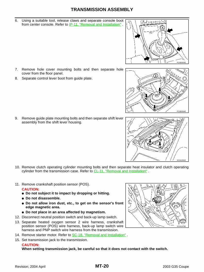
6. Using a suitable tool, release claws and separate console bootfrom center console. Refer to IP-11, "Removal and Installation" .
7. Remove hole cover mounting bolts and then separate holecover from the floor panel.
8. Separate control lever boot from guide plate.
9. Remove guide plate mounting bolts and then separate shift leverassembly from the shift lever housing.
10. Remove clutch operating cylinder mounting bolts and then separate heat insulator and clutch operatingcylinder from the transmission case. Refer to CL-11, "Removal and Installation" .
11. Remove crankshaft position sensor (POS).CAUTION:● Do not subject it to impact by dropping or hitting.● Do not disassemble.● Do not allow iron dust, etc., to get on the sensor's front
edge magnetic area.● Do not place in an area affected by magnetism.
12. Disconnect neutral position switch and back-up lamp switch.13. Separate heated oxygen sensor 2 wire harness, crankshaft
position sensor (POS) wire harness, back-up lamp switch wireharness and PNP switch wire harness from the transmission.
14. Remove starter motor. Refer to SC-18, "Removal and Installation" .15. Set transmission jack to the transmission.
CAUTION:When setting transmission jack, be careful so that it does not contact with the switch.
PCIB0063E
PCIB0064E
SCIA1591E
SCIA1476E
TRANSMISSION ASSEMBLY
MT-21
D
E
F
G
H
I
J
K
L
M
A
B
MT
Revision; 2004 April 2003 G35 Coupe
16. Remove rear engine mounting member. Refer to EM-93,"Removal and Installation" .
17. Remove engine and transmission mounting bolts with powertool.
18. Remove transmission from the vehicle.
INSTALLATIONInstall in the reverse order of removal procedure, following the cautions below:● When installing transmission to the engine, install mounting bolts in accordance with the standards below.
LHD Model
CAUTION:● When installing, be careful to avoid interference between transmission main drive shaft and clutch
cover.● Refer to MT-15, "INSTALLATION" and MT-17, "INSPECTION AFTER INSTALLATION" for control
lever installation information. ● After installation, check for oil leakage, oil level and proper operation of shifting mechanism.
SCIA1531E
Bolt No. 1 2 3 4 5
Quantity 1 5 2 2 2
“ ” mm (in)55
(2.17)65
(2.56)50
(1.97)35
(1.38)65
(2.56)
Tightening torqueN·m (kg-m, ft-lb)
75(7.7, 55)
55.4(5.7, 41)
46.6(4.8, 34)
55.4(5.7,41)
PCIB0700E
MT-22
TRANSMISSION ASSEMBLY
Revision; 2004 April 2003 G35 Coupe
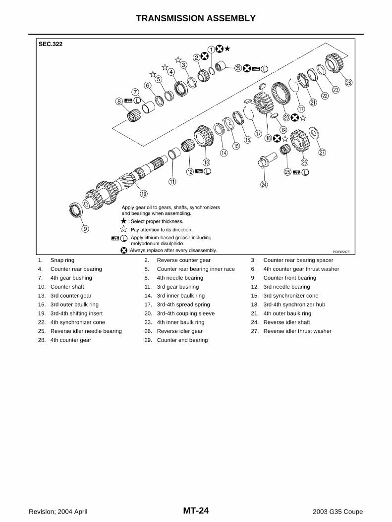
Component Parts Drawing ACS006ED
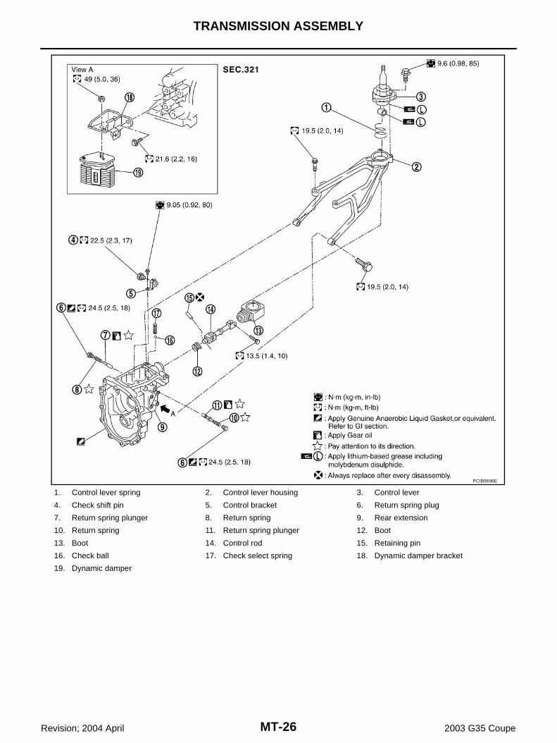
CASE COMPONENTS
1. Front cover gasket 2. Front cover 3. Withdrawal lever ball pin
2. Remove check select spring and check ball from rear extension.
3. Drive out retaining pin using a pin punch [6 mm (0.24 in) dia.],and remove control rod.
4. Remove neutral position switch, plunger and back-up lampswitch from rear extension.
5. Remove control bracket mounting bolts. Then remove checkshift pin and control bracket as one unit from rear extension.
PCIB0708E
PCIB0599E
PCIB0709E
PCIB0710E
MT-28
TRANSMISSION ASSEMBLY
Revision; 2004 April 2003 G35 Coupe
6. Remove right and left return spring plugs. Then remove returnspring and return spring plunger from rear extension.CAUTION:Return springs and return spring plungers have differentlengths for right and left sides. Identify right and left sideand then store.
7. Remove rear oil seal from rear extension using the oil sealpuller.
8. Remove rear extension mounting bolts. Using a soft hammer,tap rear extension assembly to remove.
9. Remove control lever housing mounting bolts and control leverhousing from rear extension.
10. Remove striking rod oil seal from rear extension. Refer to MT-22, "CASE COMPONENTS" .
11. Remove rear extension oil gutter mounting bolt and rear exten-sion oil gutter from rear extension. Refer to MT-22, "CASECOMPONENTS" .
13. Remove reverse idler shaft from adapter plate.
14. Remove withdrawal lever ball pin and washer from front cover.15. Remove front cover mounting bolts. Then remove front cover
and front cover gasket from transmission case.
PCIB0711E
Tool number : KV381054S0 ( – )
PCIB0196E
PCIB0712E
PCIB0713E
PCIB0230E
TRANSMISSION ASSEMBLY
MT-29
D
E
F
G
H
I
J
K
L
M
A
B
MT
Revision; 2004 April 2003 G35 Coupe
16. Remove front cover oil seal from front cover using a flat-bladedscrewdriver. CAUTION:Be careful not to damage front cover mating surface.
17. Remove baffle plate mounting nut from transmission case.
18. Remove snap ring from main drive gear bearing using snap ringpliers.
19. Carefully tap on transmission case to separate it from adapterplate using a soft hummer.
20. Remove counter front bearing from transmission case.21. Remove oil gutter from transmission case.
PCIB0714E
SCIA1443E
PCIB0715E
SCIA1687E
PCIB0436E
MT-30
TRANSMISSION ASSEMBLY
Revision; 2004 April 2003 G35 Coupe
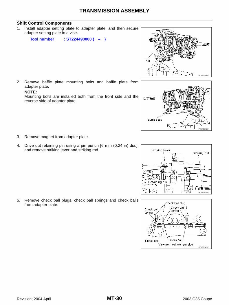
Shift Control Components1. Install adapter setting plate to adapter plate, and then secure
adapter setting plate in a vise.
2. Remove baffle plate mounting bolts and baffle plate fromadapter plate.NOTE:Mounting bolts are installed both from the front side and thereverse side of adapter plate.
3. Remove magnet from adapter plate.
4. Drive out retaining pin using a pin punch [6 mm (0.24 in) dia.],and remove striking lever and striking rod.
6. Remove 3rd-4th control lever mounting bolts and 3rd-4th controllever from adapter plate.
7. Remove shifter cap from 3rd-4th control lever.
8. Remove check ball plug, check ball spring and check ball fromadapter plate.
9. Drive out retaining pin using a pin punch [6mm (0.24in) dia.],and remove 3rd-4th fork rod bracket and 3rd-4th fork rod.
10. Drive out retaining pin using a pin punch [6 mm (0.24 in) dia.],and remove 3rd-4th fork rod (reversal side) and 3rd-4th shiftfork.
PCIB0235E
PCIB0144E
PCIB0717E
PCIB0718E
MT-32
TRANSMISSION ASSEMBLY
Revision; 2004 April 2003 G35 Coupe
11. Remove check balls and interlock pin from adapter plate.
12. Drive out retaining pin using a pin punch [6 mm (0.24 in) dia.],and remove 1st-2nd fork rod and 1st-2nd shift fork.
13. Remove interlock plunger and interlock pin from adapter plate.
14. Drive out retaining pin using a pin punch [6 mm (0.24 in) dia.],and remove reverse fork rod and reverse shift fork.
15. Remove check balls from adapter plate.
PCIB0146E
PCIB0602E
PCIB0147E
SCIA1447E
PCIB0148E
TRANSMISSION ASSEMBLY
MT-33
D
E
F
G
H
I
J
K
L
M
A
B
MT
Revision; 2004 April 2003 G35 Coupe
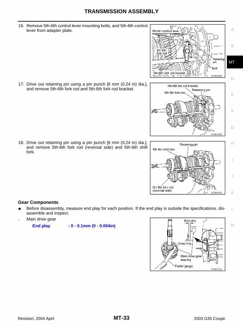
16. Remove 5th-6th control lever mounting bolts, and 5th-6th controllever from adapter plate.
17. Drive out retaining pin using a pin punch [6 mm (0.24 in) dia.],and remove 5th-6th fork rod and 5th-6th fork rod bracket.
18. Drive out retaining pin using a pin punch [6 mm (0.24 in) dia.],and remove 5th-6th fork rod (reversal side) and 5th-6th shiftfork.
Gear Components● Before disassembly, measure end play for each position. If the end play is outside the specifications, dis-
assemble and inspect.– Main drive gear
PCIB0238E
PCIB0720E
PCIB0412E
End play : 0 - 0.1mm (0 - 0.004in)
PCIB0721E
MT-34
TRANSMISSION ASSEMBLY
Revision; 2004 April 2003 G35 Coupe
– Main shaft rear side
– Counter gear
1. After removing snap ring, remove reverse synchronizer assem-bly and reverse main gear from main shaft using a puller.
2. Remove reverse main needle bearing from main shaft.
3. Remove main shaft bearing retainer mounting bolts and mainshaft bearing retainers from adapter plate.
4. After removing snap ring, remove reverse counter gear andcounter rear bearing spacer using a puller.
End play : 0 - 0.1mm (0 - 0.004in)
PCIB0722E
End play : 0 - 0.1mm (0 - 0.004in)
PCIB0723E
Tool number : Commercial service tool
PCIB0724E
PCIB0725E
Tool number : Commercial service tool
PCIB0726E
TRANSMISSION ASSEMBLY
MT-35
D
E
F
G
H
I
J
K
L
M
A
B
MT
Revision; 2004 April 2003 G35 Coupe
5. Remove snap ring from main shaft bearing.
6. Remove main shaft assembly and counter shaft assemblytogether from adapter plate.
7. Remove counter rear bearing from adapter plate.
8. Remove main drive gear, main pilot bearing, pilot bearing spacer and 5th baulk ring from main shaft.
9. Remove snap ring from main drive gear using snap ring pliers.
SCIA1691E
PCIB0727E
PCIB0728E
PCIB0729E
MT-36
TRANSMISSION ASSEMBLY
Revision; 2004 April 2003 G35 Coupe
10. Set a puller on main drive gear bearing, and remove main drivegear bearing from main drive gear using a press.
11. Set a puller on 4th main gear, and remove reverse main gearbushing, main shaft bearing and 4th main gear from main shaftusing a press.
12. Remove 3rd-4th main spacer from main shaft.
13. Set a puller on 1st main gear, and remove 3rd main gear and 1stmain gear from main shaft using a press.
CAUTION:Be careful not to damage baulk ring.
14. Remove 1st needle bearing from main shaft.
15. Set a puller on 2nd main gear, and remove 1st-2nd synchronizerassembly and 2nd main gear from main shaft using a press.
CAUTION:Be aware that when using the press, if the main shaft gearpositioner catches on the V-block, etc., the main shaft couldbe damaged.
16. Remove 2nd needle bearing from the main shaft.
Tool number : Commercial service tool
PCIB0730E
Tool number : Commercial service tool
PCIB0731E
Tool number : Commercial service tool
PCIB0732E
Tool number : Commercial service tool
PCIB0733E
TRANSMISSION ASSEMBLY
MT-37
D
E
F
G
H
I
J
K
L
M
A
B
MT
Revision; 2004 April 2003 G35 Coupe
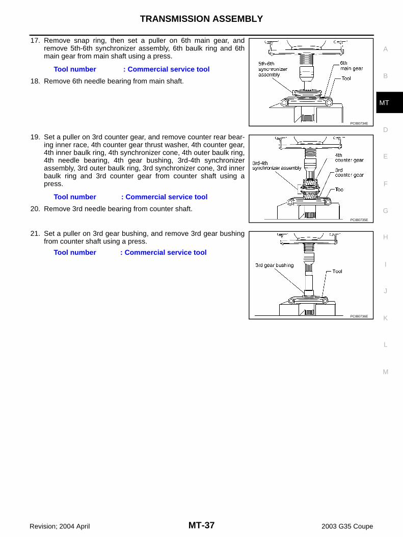
17. Remove snap ring, then set a puller on 6th main gear, andremove 5th-6th synchronizer assembly, 6th baulk ring and 6thmain gear from main shaft using a press.
18. Remove 6th needle bearing from main shaft.
19. Set a puller on 3rd counter gear, and remove counter rear bear-ing inner race, 4th counter gear thrust washer, 4th counter gear,4th inner baulk ring, 4th synchronizer cone, 4th outer baulk ring,4th needle bearing, 4th gear bushing, 3rd-4th synchronizerassembly, 3rd outer baulk ring, 3rd synchronizer cone, 3rd innerbaulk ring and 3rd counter gear from counter shaft using apress.
20. Remove 3rd needle bearing from counter shaft.
21. Set a puller on 3rd gear bushing, and remove 3rd gear bushingfrom counter shaft using a press.
Tool number : Commercial service tool
PCIB0734E
Tool number : Commercial service tool
PCIB0735E
Tool number : Commercial service tool
PCIB0736E
MT-38
TRANSMISSION ASSEMBLY
Revision; 2004 April 2003 G35 Coupe
INSPECTION AFTER DISASSEMBLYShift Control ComponentsIf the contact surfaces of striking lever, fork rod, shift fork, etc. haveexcessive wear, abrasion, bend, or any other damage, replace thecomponent.
Gear and Shaft ComponentsIf the contact surfaces of each gear, main shaft, main drive gear andcounter shaft, etc. have damage, peeling, abrasion, dent, bend, orany other damage, replace the component.
SCIA1681E
PCIB0437E
PCIB0438E
TRANSMISSION ASSEMBLY
MT-39
D
E
F
G
H
I
J
K
L
M
A
B
MT
Revision; 2004 April 2003 G35 Coupe
Synchronizer Components● If the contact surfaces of coupling sleeves, synchronizer hubs
and shifting inserts have damage or abrasion, replace the com-ponent.
● Each set of coupling sleeve and synchronizer hub should movesmoothly.
● If the cam surfaces of baulk rings or contact surfaces of shiftinginserts have damage or excessive wear, replace with a new one.
● If spread springs are damaged, replace with a new one.
Single-Cone Synchronizer (5th and 6th)● Push baulk ring on cone and measure baulk ring back surface
clearance at two locations or more on opposite sides. Find theaverage value, and replace baulk ring if it is below the limitvalue.
NOTE:● 5th and 6th baulk rings have three spaces that two gear teeth
are missing as shown in the figure.
SMT387A
SCIA0608J
ClearanceStandard : 0.7 - 1.25 mm (0.028 - 0.049 in)Limit value : 0.5 mm (0.02 in) or less
PCIB0738E
PCIB0743E
MT-40
TRANSMISSION ASSEMBLY
Revision; 2004 April 2003 G35 Coupe
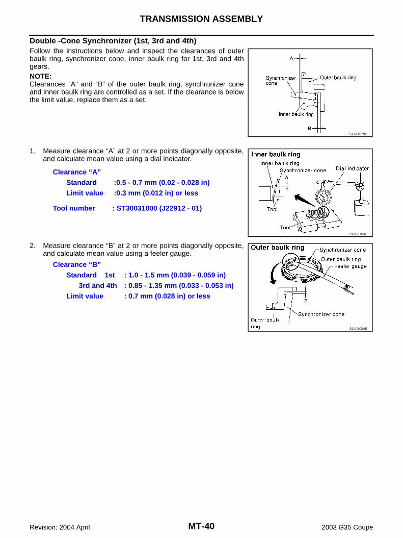
Double -Cone Synchronizer (1st, 3rd and 4th)Follow the instructions below and inspect the clearances of outerbaulk ring, synchronizer cone, inner baulk ring for 1st, 3rd and 4thgears.NOTE:Clearances “A” and “B” of the outer baulk ring, synchronizer coneand inner baulk ring are controlled as a set. If the clearance is belowthe limit value, replace them as a set.
1. Measure clearance “A” at 2 or more points diagonally opposite,and calculate mean value using a dial indicator.
1.
2. Measure clearance “B” at 2 or more points diagonally opposite,and calculate mean value using a feeler gauge.
SCIA1679E
Clearance “A”Standard :0.5 - 0.7 mm (0.02 - 0.028 in)Limit value :0.3 mm (0.012 in) or less
3rd and 4th : 0.85 - 1.35 mm (0.033 - 0.053 in)Limit value : 0.7 mm (0.028 in) or less
SCIA1084E
TRANSMISSION ASSEMBLY
MT-41
D
E
F
G
H
I
J
K
L
M
A
B
MT
Revision; 2004 April 2003 G35 Coupe
NOTE:1st and 4th baulk rings have three spaces that one gear tooth ismissing as shown in the figure.
Triple-Cone Synchronizer (2nd)Follow the instructions below and inspect the clearances of 2ndouter baulk ring, 2nd synchronizer cone and 2nd inner baulk ring. NOTE:Clearances “A”, “B” and “C” of 2nd outer baulk ring, 2nd synchro-nizer cone and 2nd inner baulk ring are controlled as a set. If theclearance is below the limit value, replace them as a set.
1. Push 2nd outer baulk ring on 2nd main gear taper cone. Mea-sure clearance “A” at 2 or more points diagonally opposite, andcalculate mean value using a feeler gauge.
PCIB0399E
PCIB0756E
Clearance “A”Standard value : 0.6 - 1.3 mm (0.024 - 0.051 in)Limit value : 0.3 mm (0.012 in) or less
PCIB0740E
MT-42
TRANSMISSION ASSEMBLY
Revision; 2004 April 2003 G35 Coupe
2. Measure clearance “B” at 2 or more points diagonally opposite,and calculate mean value using a feeler gauge.
3. Push 2nd outer baulk ring on 2nd main gear taper cone. Mea-sure clearance “C” at 2 or more points diagonally opposite, andcalculate mean value using a feeler gauge.
NOTE:2nd baulk ring has three spaces that the gear teeth are missingas shown in the figure.
Reverse Synchronizer Push baulk ring on cone and measure baulk ring back surface clear-ance at two locations or more on opposite sides. Find the averagevalue, and replace baulk ring if it is below the limit value.
Clearance “B”Standard value : 0.85 - 1.35 mm (0.033 - 0.053
in)Limit value : 0.7 mm (0.028 in) or less
PCIB0402E
Clearance “C”Standard value : 0.7 - 1.25 mm (0.028 - 0.049 in)Limit value : 0.3 mm (0.012 in) or less
PCIB0737E
PCIB0404E
ClearanceStandard : 0.75 - 1.2 mm (0.03 - 0.047 in)
Limit value : 0.5 mm (0.02 in) or less
PCIB0738E
TRANSMISSION ASSEMBLY
MT-43
D
E
F
G
H
I
J
K
L
M
A
B
MT
Revision; 2004 April 2003 G35 Coupe
NOTE:Reverse baulk ring has three spaces that two gear teeth are missing,and each space has groove for identification as shown in the figure.
BearingIf the bearings do not rotate smoothly or the contact surface on ballor race is damaged or peeled, replace with a new one.
5th-6th synchronizer hub.CAUTION:● Do not reuse 5th-6th synchronizer hub and 5th-6th cou-
pling sleeve.● Install 5th-6th coupling sleeve with the larger chamfer on
the rear side.
CAUTION:Be careful with the shape of shifting insert to avoid misas-sembly.
PCIB0749E
SMT418A
PCIB0739E
PCIB0741E
MT-44
TRANSMISSION ASSEMBLY
Revision; 2004 April 2003 G35 Coupe
2. Install 5th-6th spread springs in 5th-6th shifting inserts.CAUTION:Install the hook of each spread spring onto separate shift-ing inserts.
3. Install 6th needle bearing, 6th main gear, 6th baulk ring and 5th-6th synchronizer assembly onto main shaft using a press andthe inserter.
CAUTION:The rear side of synchronizer hub has three oil grooves.When press fitting, install the rear side to the rearward.
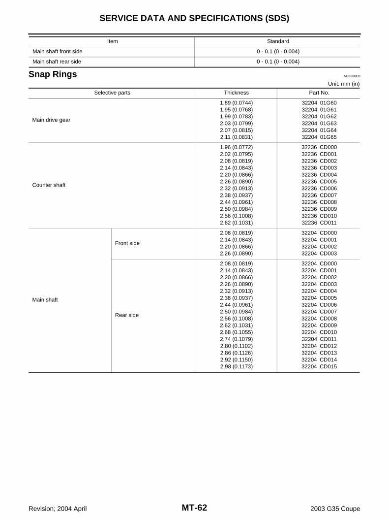
4. Select and install snap ring onto the front side of main shaft sothat the end play comes within the specifications. Refer to MT-62, "Snap Rings" .
CAUTION:Do not reuse snap ring.
PCIB0607E
Tool number : ST30911000 ( — )
PCIB0742E
SCIA2699E
End play : 0 - 0.1 mm (0 - 0.004 in)
PCIB0609E
TRANSMISSION ASSEMBLY
MT-45
D
E
F
G
H
I
J
K
L
M
A
B
MT
Revision; 2004 April 2003 G35 Coupe
5. Install 1st-2nd coupling sleeve and 1st-2nd shifting inserts onto1st-2nd synchronizer hub.CAUTION:● Do not reuse 1st-2nd synchronizer hub and 1st-2nd cou-
pling sleeve.● Install 1st-2nd coupling sleeve with the thicker flange
faced the front side.
CAUTION:Be careful with the shape of shifting insert to avoid misas-sembly.
6. Install 1st-2nd spread spring in 1st-2nd shifting inserts onto 1st-2nd synchronizer hub.CAUTION:Install hook of each spread spring onto separate shiftinginserts.
7. Install 2nd needle bearing, 2nd main gear, 2nd inner baulk ring,2nd synchronizer cone, 2nd outer baulk ring and 1st-2nd syn-chronizer assembly onto main shaft using a press and the sup-port ring.
PCIB0610E
PCIB0741E
PCIB0611E
Tool number : ST27861000 ( — )
PCIB0744E
MT-46
TRANSMISSION ASSEMBLY
Revision; 2004 April 2003 G35 Coupe
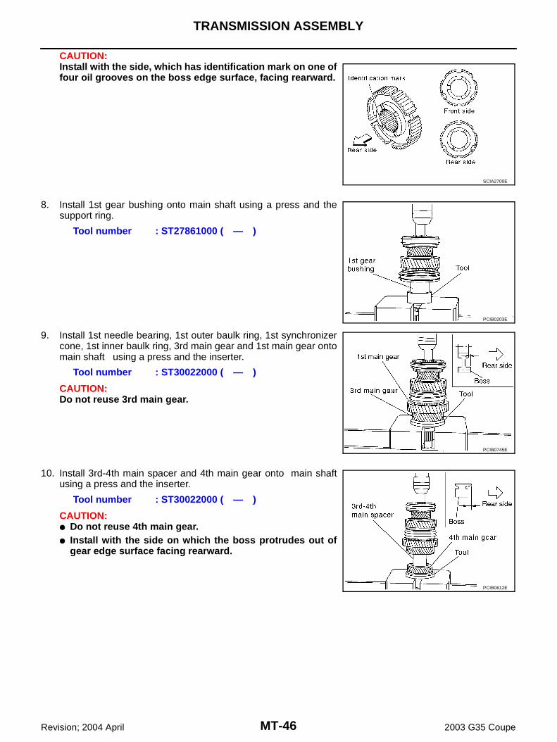
CAUTION:Install with the side, which has identification mark on one offour oil grooves on the boss edge surface, facing rearward.
8. Install 1st gear bushing onto main shaft using a press and thesupport ring.
9. Install 1st needle bearing, 1st outer baulk ring, 1st synchronizercone, 1st inner baulk ring, 3rd main gear and 1st main gear ontomain shaft using a press and the inserter.
CAUTION:Do not reuse 3rd main gear.
10. Install 3rd-4th main spacer and 4th main gear onto main shaftusing a press and the inserter.
CAUTION:● Do not reuse 4th main gear.● Install with the side on which the boss protrudes out of
gear edge surface facing rearward.
SCIA2700E
Tool number : ST27861000 ( — )
PCIB0203E
Tool number : ST30022000 ( — )
PCIB0745E
Tool number : ST30022000 ( — )
PCIB0612E
TRANSMISSION ASSEMBLY
MT-47
D
E
F
G
H
I
J
K
L
M
A
B
MT
Revision; 2004 April 2003 G35 Coupe
11. Install main shaft bearing onto main shaft using a press and theinserter.
12. Install reverse main gear bushing onto main shaft using a pressand the inserter.
13. Install 3rd gear bushing onto counter shaft using a press and theinserter.
14. Install 3rd-4th coupling sleeve and 3rd-4th shifting inserts onto3rd-4th synchronizer hub.CAUTION:● Do not reuse 3rd-4th synchronizer hub and 3rd-4th cou-
pling sleeve.● Install 3rd-4th coupling sleeve with the thicker flange
faced the front side.
CAUTION:Be careful with the shape of shifting insert to avoid misas-sembly.
Tool number : ST30911000 ( — )
PCIB0405E
Tool number : ST30911000 ( — )
PCIB0206E
Tool number : ST30911000 ( — )
PCIB0406E
PCIB0613E
PCIB0741E
MT-48
TRANSMISSION ASSEMBLY
Revision; 2004 April 2003 G35 Coupe
15. Install 3rd-4th spread springs into 3rd-4th shifting insert.CAUTION:Install the hook of each spread spring onto separate shift-ing inserts.
16. Install 3rd needle bearing, 3rd counter gear, 3rd inner baulk ring,3rd synchronizer cone, 3rd outer baulk ring and 3rd-4th synchro-nizer assembly onto counter shaft using a press and the drift.
17. Install 4th outer baulk ring, 4th synchronizer cone, 4th innerbaulk ring, 4th gear bushing, 4th needle bearing, 4th countergear and 4th counter shaft thrust washer onto counter shaftusing a press and the drift.
18. Install counter rear bearing inner race onto counter shaft using apress and the drift.
19. Install main drive bearing onto main drive gear using a pressand the drift.
PCIB0614E
Tool number : ST30911000 ( — )
PCIB0208E
Tool number : KV40100630 (J26029)
PCIB0746E
Tool number : ST30032000 (J26010-01)
PCIB0210E
Tool number : KV32102700 ( — )
PCIB0747E
TRANSMISSION ASSEMBLY
MT-49
D
E
F
G
H
I
J
K
L
M
A
B
MT
Revision; 2004 April 2003 G35 Coupe
20. Select and install snap ring on main drive gear so that comeswithin the specifications. Refer to MT-62, "Snap Rings" .
CAUTION:Do not reuse snap ring.
21. Install 5th baulk ring, pilot bearing spacer, main pilot bearing and main drive gear onto main shaft.
22. Install main shaft and counter shaft combined in one unit toadapter plate, and secure main shaft bearing with a snap ring.
a. Tap main shaft bearing slightly via brass bar or the equivalent toinstall snap ring.
b. After installing snap ring, hammer snap ring and adapter plateslightly in the reverse direction to make them in contact witheach other.CAUTION:Do not reuse snap ring.
24. Apply genuine medium strength locking sealant or equivalent(refer to GI section) to the end of the bolt (first 3 to 4 threads).Install main shaft bearing retainer onto adapter plate, andtighten bolts to the specified torque. Refer to MT-22, "CASECOMPONENTS" .
End play : 0 - 0.1 mm (0 - 0.004 in)
PCIB0721E
PCIB0151E
PCIB0719E
PCIB0725E
MT-50
TRANSMISSION ASSEMBLY
Revision; 2004 April 2003 G35 Coupe
25. Install reverse coupling sleeve and reverse shifting inserts ontoreverse synchronizer hub.CAUTION:● Do not reuse reverse synchronizer hub and reverse cou-
pling sleeve.● Install reverse coupling sleeve with the flat flange on the
rear side.
CAUTION:Be careful with the shape of shifting insert to avoid misas-sembly.
26. Install spread springs into shifting insert.CAUTION:Install the hook of each spread spring onto separate shift-ing inserts.
PCIB0617E
PCIB0741E
PCIB0618E
TRANSMISSION ASSEMBLY
MT-51
D
E
F
G
H
I
J
K
L
M
A
B
MT
Revision; 2004 April 2003 G35 Coupe
27. Install reverse main needle bearing, reverse main gear, reversebaulk ring and reverse synchronizer assembly onto main shaftusing a press, the press plate and the drift.
CAUTION:When installing, face the side with three grooves to thefront side.
28. Select and install a snap ring to the main shaft rear side so thatthe end play comes within the standard value. Refer to MT-62,"Snap Rings" .
CAUTION:Do not reuse snap ring.
Tool number (A) : KV32103300 (J46529)Tool number (B) : ST01530000 ( — )
PCIB0748E
PCIB0221E
End play : 0 - 0.1 mm (0 - 0.004 in)
PCIB0722E
MT-52
TRANSMISSION ASSEMBLY
Revision; 2004 April 2003 G35 Coupe
29. Install counter rear bearing spacer and reverse counter gearusing a press and the drift.
CAUTION:● Do not reuse reverse counter gear.● When installing counter rear bearing spacer, maker's
stamp should face to the rear.
30. Select and install a snap ring to the counter shaft so that the endplay comes within the standard value. Refer to MT-62, "SnapRings" .
CAUTION:Do not reuse snap ring.
Shift Control Components1. Install 5th-6th shift fork to 5th-6th coupling sleeve.2. Install 5th-6th fork rod (reversal side) to 5th-6th shift fork.3. Drive retaining pin into 5th-6th shift fork using a pin punch [6 mm
(0.24in) dia.]. CAUTION:Do not reuse retaining pin.
4. Install 5th-6th fork rod to adapter plate.5. Install 5th-6th fork rod bracket to 5th-6th fork rod. 6. Drive retaining pin into 5th-6th fork rod bracket using a pin
punch [6 mm (0.24in) dia.]. CAUTION:Do not reuse retaining pin.
Tool number : ST23860000 ( — )
PCIB0411E
End play : 0 - 0.1 mm (0 - 0.004 in)
PCIB0723E
PCIB0412E
PCIB0238E
TRANSMISSION ASSEMBLY
MT-53
D
E
F
G
H
I
J
K
L
M
A
B
MT
Revision; 2004 April 2003 G35 Coupe
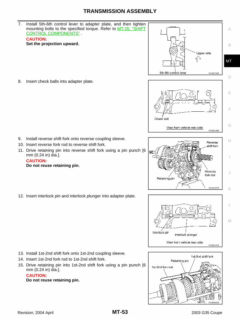
7. Install 5th-6th control lever to adapter plate, and then tightenmounting bolts to the specified torque. Refer to MT-25, "SHIFTCONTROL COMPONENTS" .CAUTION:Set the projection upward.
8. Insert check balls into adapter plate.
9. Install reverse shift fork onto reverse coupling sleeve.10. Insert reverse fork rod to reverse shift fork.11. Drive retaining pin into reverse shift fork using a pin punch [6
mm (0.24 in) dia.]. CAUTION:Do not reuse retaining pin.
12. Insert interlock pin and interlock plunger into adapter plate.
13. Install 1st-2nd shift fork onto 1st-2nd coupling sleeve.14. Insert 1st-2nd fork rod to 1st-2nd shift fork.15. Drive retaining pin into 1st-2nd shift fork using a pin punch [6
mm (0.24 in) dia.]. CAUTION:Do not reuse retaining pin.
PCIB0750E
PCIB0148E
SCIA1447E
PCIB0147E
PCIB0602E
MT-54
TRANSMISSION ASSEMBLY
Revision; 2004 April 2003 G35 Coupe
16. Install 3rd-4th shift fork onto 3rd-4th coupling sleeve.17. Install 3rd-4th fork rod (reversal side) to 3rd-4th shift fork.18. Drive retaining pin into 3rd-4th shift fork (reversal side) using a
pin punch [6 mm (0.24 in) dia.]. CAUTION:Do not reuse retaining pin.
19. Insert interlock pin and check balls into adapter plate.
20. Install 3rd-4th fork rod to adapter plate.21. Install 3rd-4th fork rod bracket to 3rd-4th fork rod.22. Drive retaining pin into 3rd-4th fork rod bracket using a pin
punch [6 mm (0.24 in) dia.]. CAUTION:Do not reuse retaining pin.
23. Insert check ball, check ball spring into adapter plate, apply gen-uine anaerobic liquid gasket or equivalent (refer to GI section) tocheck ball plug threads, and tighten to the specified torque.Refer to MT-25, "SHIFT CONTROL COMPONENTS" .
24. Install shifter cap to 3rd-4th control lever.
PCIB0718E
PCIB0146E
PCIB0717E
PCIB0144E
TRANSMISSION ASSEMBLY
MT-55
D
E
F
G
H
I
J
K
L
M
A
B
MT
Revision; 2004 April 2003 G35 Coupe
25. Insert 3rd-4th control lever to adapter plate, and then tightenmounting bolts to the specified torque. Refer to MT-25, "SHIFTCONTROL COMPONENTS" .CAUTION:Make sure the top and bottom are oriented correctly.
26. Insert check ball spring and check ball into the adapter plate,apply genuine anaerobic liquid gasket or equivalent (refer to GIsection) to the check ball plug threads, and tighten to the speci-fied torque. Refer to MT-25, "SHIFT CONTROL COMPO-NENTS" .
27. Install striking rod to adapter plate.28. Install striking lever to striking rod.29. Drive retaining pin into striking lever using a pin punch [6 mm
(0.24 in) dia.]. CAUTION:Do not reuse retaining pin.
30. Install baffle plate onto adapter plate, and tighten mountingbolts to the specified torque.
PCIB0751E
PCIB0143E
PCIB0414E
PCIB0716E
MT-56
TRANSMISSION ASSEMBLY
Revision; 2004 April 2003 G35 Coupe
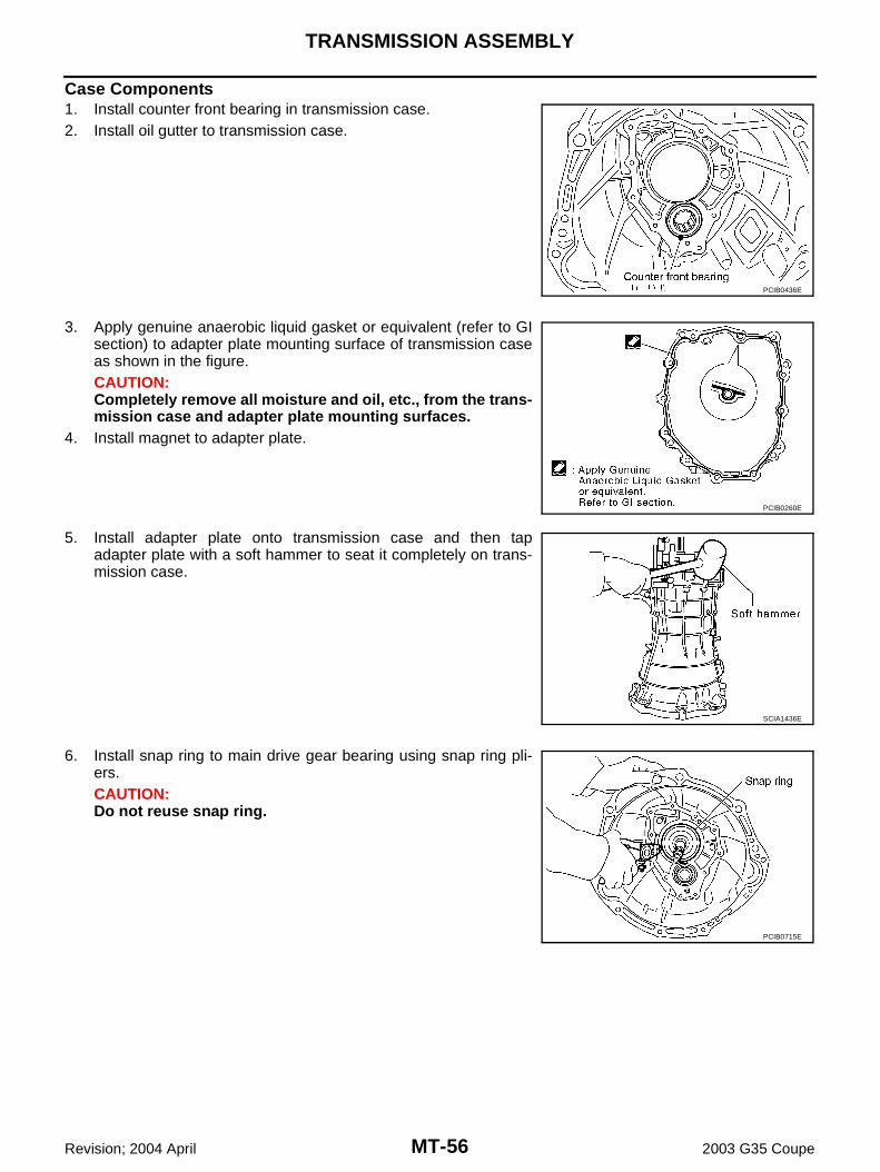
Case Components1. Install counter front bearing in transmission case.2. Install oil gutter to transmission case.
3. Apply genuine anaerobic liquid gasket or equivalent (refer to GIsection) to adapter plate mounting surface of transmission caseas shown in the figure.CAUTION:Completely remove all moisture and oil, etc., from the trans-mission case and adapter plate mounting surfaces.
4. Install magnet to adapter plate.
5. Install adapter plate onto transmission case and then tapadapter plate with a soft hammer to seat it completely on trans-mission case.
6. Install snap ring to main drive gear bearing using snap ring pli-ers.CAUTION:Do not reuse snap ring.
PCIB0436E
PCIB0260E
SCIA1436E
PCIB0715E
TRANSMISSION ASSEMBLY
MT-57
D
E
F
G
H
I
J
K
L
M
A
B
MT
Revision; 2004 April 2003 G35 Coupe
7. Tighten baffle plate mounting nut to the specified torque. Referto MT-22, "CASE COMPONENTS" .
8. Apply multi-purpose grease to the lip of front cover oil seal.Install front cover oil seal approx. 8.55-9.55 mm (0.336-0.376 in)above from the front cover edge surface using a drift.
CAUTION:● Do not reuse front cover oil seal.● When installing, do not tilt front cover oil seal.
9. Install front cover gasket and front cover to transmission case.CAUTION:Do not reuse gasket.
10. Temporarily tighten bolts in the positions shown in the figure.
11. Install remaining bolts, and tighten them by hand.CAUTION:Four bolts pointed by arrows in the figure are not reusable.
SCIA1443E
Tool number : KV38102100 (J25803-01)
PCIB0752E
PCIB0454J
PCIB0455J
MT-58
TRANSMISSION ASSEMBLY
Revision; 2004 April 2003 G35 Coupe
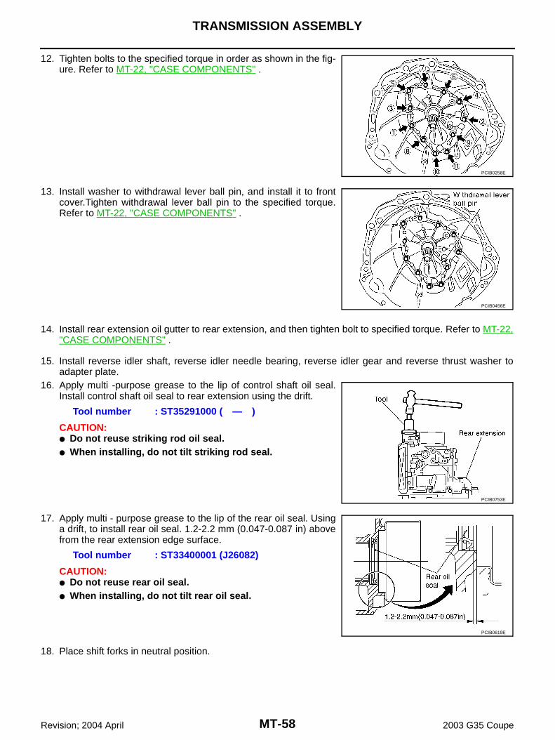
12. Tighten bolts to the specified torque in order as shown in the fig-ure. Refer to MT-22, "CASE COMPONENTS" .
13. Install washer to withdrawal lever ball pin, and install it to frontcover.Tighten withdrawal lever ball pin to the specified torque.Refer to MT-22, "CASE COMPONENTS" .
14. Install rear extension oil gutter to rear extension, and then tighten bolt to specified torque. Refer to MT-22,"CASE COMPONENTS" .
16. Apply multi -purpose grease to the lip of control shaft oil seal.Install control shaft oil seal to rear extension using the drift.
CAUTION:● Do not reuse striking rod oil seal.● When installing, do not tilt striking rod seal.
17. Apply multi - purpose grease to the lip of the rear oil seal. Usinga drift, to install rear oil seal. 1.2-2.2 mm (0.047-0.087 in) abovefrom the rear extension edge surface.
CAUTION:● Do not reuse rear oil seal.● When installing, do not tilt rear oil seal.
18. Place shift forks in neutral position.
PCIB0258E
PCIB0456E
Tool number : ST35291000 ( — )
PCIB0753E
Tool number : ST33400001 (J26082)
PCIB0619E
TRANSMISSION ASSEMBLY
MT-59
D
E
F
G
H
I
J
K
L
M
A
B
MT
Revision; 2004 April 2003 G35 Coupe
19. Apply genuine anaerobic liquid gasket or equivalent (refer to GIsection) to rear extension mounting surface of adapter plate asshown in the figure.CAUTION:Completely remove all moisture, oil, etc., from the adapterplate and rear extension mating surfaces.
20. Install rear extension to transmission case, and tighten mountingbolts to the specified torque in order as shown in the figure.Refer to MT-22, "CASE COMPONENTS" .
21. Install control lever housing to rear extension, and then tightenmounting bolts to the specified torque. Refer toMT-25, "SHIFTCONTROL COMPONENTS" .
22. Insert return spring and plunger into the rear extension, applygenuine anaerobic liquid gasket or equivalent (refer to GI sec-tion) to the return spring plug threads, and then tighten to thespecified torque. Refer to MT-25, "SHIFT CONTROL COMPO-NENTS" .
CAUTION:The right and left return springs and plungers are different,so make sure they are installed correctly.
23. Install shift check pin and control bracket as a one unit to rearextension, and then tighten mounting bolts to specified torque.Refer to MT-25, "SHIFT CONTROL COMPONENTS" .
24. After screwing plunger, neutral position switch and back-up lampswitch to rear extension with 1-2 pitches, apply genuine anaero-bic liquid gasket or equivalent (refer to GI section) to the switchthreads, and tighten them to the specified torque. Refer to MT-22, "CASE COMPONENTS" .
PCIB0175E
PCIB0754E
Return spring identification mark Plunger notch
RH Brown No
LH Blue Yes
SCIA1607E
PCIB0710E
MT-60
TRANSMISSION ASSEMBLY
Revision; 2004 April 2003 G35 Coupe
25. Drive retaining pin into control rod using a pin punch [6 mm(0.24 in) dia.].CAUTION:Do not reuse retaining pin.
26. Insert check select spring and check ball into rear extension.
27. Install rear extension upper cover gasket and rear extensionupper cover to rear extension.CAUTION:● Do not reuse rear extension upper cover gasket.● Avoid tangling check select spring.
28. Tighten rear extension upper cover bolts to specified torque inorder as shown in the figure. Refer to MT-22, "CASE COMPO-NENTS" .