READ ENTIRE MANUAL AND REVIEW ALL DOCUMENTATION BEFORE ATTEMPTING SYSTEM INSTALLATION
FOR SERVICE OR INSTALLATION INFORMATION: TELEPHONE: (610) 868-5400 (24 HR. HOTLINE)
FAX: (610) 954-8227
115894A – Hypernova System Users Manual 3
This unit contains LETHAL VOLTAGES. All repairs and service should be performed by AUTHORIZED SERVICE PERSONNEL ONLY! There are NO USER SERVICEABLE PARTS inside this unit.
IMPORTANT SAFEGUARDS When using electrical equipment, you should always follow basic safety precautions, including the following:
1. READ AND FOLLOW ALL SAFETY INSTRUCTIONS.
2. Do not install the system outdoors. 3. Do not install near gas or electric heaters or in other high-temperature
locations. 4. Use caution when servicing batteries. Depending on battery type, batteries
contain either acid or alkali and can cause burns to skin and eyes. If battery fluid is spilled on skin or in the eyes, flush with fresh water and contact a physician immediately.
5. Equipment should be mounted in locations where unauthorized personnel
will not readily subject it to tampering. 6. The use of accessory equipment not recommended by Manufacturer may
cause an unsafe condition and void the warranty. 7. Do not use this equipment for other than its intended use. 8. Qualified service personnel must perform all servicing of this equipment.
SAVE THESE INSTRUCTIONS The installation and use of this product must comply with all national, federal, state, municipal, or local codes that apply. If you need help, please call Service.
115894A – Hypernova System Users Manual 4
User’s Guide An on-site permanent log of the inspection, testing, and maintenance of the emergency electrical power supply system shall be maintained in accordance with the Manufacturer's operating manual. The log shall include: The date on which the inspection, testing, and maintenance exercise was carried out The name of the person(s) who performed the inspection, testing, and maintenance. A note of any unsatisfactory condition observed or discovered, and the steps taken to correct the condition
115894A – Hypernova System Users Manual 5
Table of Contents C H A P T E R 1 INTRODUCTION ...................................................................................................... 6 C H A P T E R 2 ENVIRONMENT ....................................................................................................... 8 C H A P T E R 3 STARTUP AND SHUTDOWN PROCEDURE ........................................................ 9 C H A P T E R 4 OPERATION ........................................................................................................... 12 C H A P T E R 5 FRONT PANEL DISPLAY ..................................................................................... 13 C H A P T E R 6 SPECIFICATIONS .................................................................................................. 17 C H A P T E R 7 MAINTENANCE AND SERVICE ......................................................................... 18
115894A – Hypernova System Users Manual 6
C H A P T E R 1
INTRODUCTION Keep this manual and the System Installation Guide in the folder mounted inside the unit. This unit is a micro-controller controlled PWM (Pulse Width Modulated) pure sine wave based DC to AC power inverter utilizing IGBT technology. It integrates a fully automatic battery charger, a solid-state transfer system, control circuitry, self testing and recording digital meter display, and maintenance free sealed lead calcium type batteries. The system components are carefully matched to make the unit a completely self-contained, fully automatic standby power source for operation on all types of lighting loads. The batteries are sized and tested per UL-924 and Life Safety Code ANSI / NFPA 101, providing emergency power for a minimum of 90 minutes. If the duration of a power failure is greater than the batteries storage capability, the inverter will automatically shut down when the battery voltage reaches 85% of the nominal DC voltage. This feature protects the battery from being permanently damaged from a deep discharge that could cause cell reversal. This battery protection feature is called "Low Voltage Disconnect" or L.V.D. When the AC power is restored after a full discharge, the system will be ready for another power failure within 24hrs. If another power failure occurs before the 24-hour recharge time, the run time will be decreased. The front panel display incorporates an alphanumeric 2x20 LCD character display, LED status indicators and a 4 x 4 keypad. All user interface functions are available from the front panel assembly. Utilizing a small footprint, this unit is for use with any lighting load including LED, quartz, HID, incandescent, fluorescent and halogen.
HOW TO USE THIS MANUAL This manual tells you how to start, operate, and communicate with your unit and lets you know how to get more information for special situations. Please record your unit’s model number, serial number, and part number below. You can find these numbers on the labels on the inside panel. Model Number __________________________ Serial Number __________________________ Part Number ___________________________
115894A – Hypernova System Users Manual 7
Service and Support We are committed to outstanding customer service. A service technician is available 24 hours a day, 365 days a year. Service is also available 24 hours a day to give you access to technical notes and product information. You can also visit our web site. NOTE: Please have your unit’s Serial and Model numbers available when you call; this number is located behind the right door. Contact SERVICE one of the following ways: Service Number: 610-868-5400 Service Fax: 610-954-8227 Website: www.myerseps.com
ENVIRONMENT Make sure the environment is a clean, cool, dry place with normal ventilation.
Storage Temperature Store the batteries (in the system or battery cabinet) at -18 to 40°C (0 to 104°F). Batteries have a longer shelf life if they are stored below 25°C (77°F). Keep stored batteries fully charged. Recharge the batteries every 90–180 days. The system or battery cabinet without batteries may be stored at -20 to 70°C (-4 to 158°F).
Ventilation The air around the unit must be clean, dust-free, and free of corrosive chemicals or other contaminants. Do not place the system or batteries in a sealed room or container.
Operating Temperature System can operate from 20° to 30°C (68° to 86°F) and up to 95% relative humidity. The batteries’ service life is longer if the operating temperature stays below 25°C (77°F).
Batteries The temperature should be near 25°C (77°F) for optimum battery performance. Batteries are less efficient at temperatures below 18°C (65°F), and high temperatures reduce battery life. Typically, at about 35°C (95°F), battery life is half of what it would be at a normal temperature of 25°C (77°F). At about 45°C (113°F), battery life is one-fourth of normal. Make sure that heaters, sunlight, air conditioners, or outside air vents are not directed toward the batteries. These conditions can make the temperature within battery strings vary, which can cause differences in the batteries’ voltages. Eventually, these conditions affect battery performance. If the batteries are not in the system, remember that the batteries should be installed as close as possible to the unit to reduce DC wiring costs and improve battery performance. Do not allow tobacco smoking, sparks, or flames in the system location because hydrogen is concentrated under the vent cap of each cell of the battery. Hydrogen is highly explosive, and it is hard to detect because it is colorless, odorless, and lighter than air. Every type of battery can produce hydrogen gas, even sealed maintenance-free batteries. The gas is vented through the vent caps and into the air, mainly when the unit is charging the batteries. The batteries produce the most hydrogen when maximum charging current is present when recharging batteries; the batteries produce minimal hydrogen gas during float charging. The amount of current that the charger supplies to the batteries (not the battery ampere-hour) determines how much hydrogen is produced.
High Altitude Operation Maximum elevation is 3000m (10,000 ft). Derating is 1% per 300m (1000ft) above 3000m (10,000 ft).
115894A – Hypernova System Users Manual 9
C H A P T E R 3
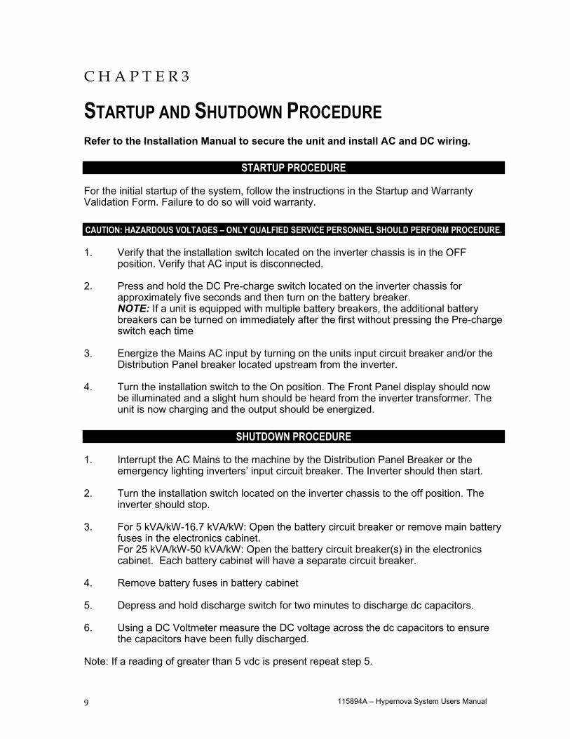
STARTUP AND SHUTDOWN PROCEDURE Refer to the Installation Manual to secure the unit and install AC and DC wiring.
STARTUP PROCEDURE For the initial startup of the system, follow the instructions in the Startup and Warranty Validation Form. Failure to do so will void warranty. CAUTION: HAZARDOUS VOLTAGES – ONLY QUALFIED SERVICE PERSONNEL SHOULD PERFORM PROCEDURE. 1. Verify that the installation switch located on the inverter chassis is in the OFF
position. Verify that AC input is disconnected. 2. Press and hold the DC Pre-charge switch located on the inverter chassis for
approximately five seconds and then turn on the battery breaker. NOTE: If a unit is equipped with multiple battery breakers, the additional battery breakers can be turned on immediately after the first without pressing the Pre-charge switch each time
3. Energize the Mains AC input by turning on the units input circuit breaker and/or the
Distribution Panel breaker located upstream from the inverter. 4. Turn the installation switch to the On position. The Front Panel display should now
be illuminated and a slight hum should be heard from the inverter transformer. The unit is now charging and the output should be energized.
SHUTDOWN PROCEDURE
1. Interrupt the AC Mains to the machine by the Distribution Panel Breaker or the
emergency lighting inverters’ input circuit breaker. The Inverter should then start. 2. Turn the installation switch located on the inverter chassis to the off position. The
inverter should stop. 3. For 5 kVA/kW-16.7 kVA/kW: Open the battery circuit breaker or remove main battery
fuses in the electronics cabinet. For 25 kVA/kW-50 kVA/kW: Open the battery circuit breaker(s) in the electronics
cabinet. Each battery cabinet will have a separate circuit breaker. 4. Remove battery fuses in battery cabinet 5. Depress and hold discharge switch for two minutes to discharge dc capacitors. 6. Using a DC Voltmeter measure the DC voltage across the dc capacitors to ensure
the capacitors have been fully discharged. Note: If a reading of greater than 5 vdc is present repeat step 5.
115894A – Hypernova System Users Manual 10
CAUTION: HAZARDOUS VOLTAGES STILL EXIST AT THE BATTERY TERMINAL BLOCK AND
WITHIN THE SYSTEM. AUTHORIZED SERVICE TECHNICIANS MUST DISCHARGE DC CAPACITORS AND TURN OFF UTILITY POWER BEFORE SERVICING EQUIPMENT.
CAUTION: DO NOT LEAVE THE SYSTEM SHUTDOWN FOR A PROLONGED LENGTH OF TIME.
LEAD BASED BATTERIES WILL EXPERIENCE PERMANENT DAMAGE FROM LACK OF CHARGING.
MAINTENANCE BYPASS PROCEDURE
CAUTION: HAZARDOUS VOLTAGES – ONLY QUALFIED SERVICE PERSONNEL SHOULD PERFORM PROCEDURE.
MAINTENANCE BYPASS SHOULD NOT BE PERFORMED WHEN SYSTEM IS IN BATTERY EMERGENCY MODE.
System Into Bypass Mode
1. Open left-hand door. Locate Maintenance Bypass Switch. NOTE: Make sure the emergency lighting inverter is not running on battery by checking the front meter panel indicator light (ON BATTERY) or front panel display.
2. Turn Maintenance Bypass Switch from normal mode (UPS) to bypass mode (BYPASS). 3. Locate Installation Switch behind left-hand door on right-hand wall. Turn the Installation
Switch to the (OFF) position. 4. Locate Input Circuit Breaker (CB1) behind left-hand door. Turn the Input Circuit Breaker to
the (OFF) position. 5. Remove screws to open the right-hand doors. Locate the Main Battery Circuit Breaker(s) on
lower left. Turn all Battery Circuit Breaker(s) to the (OFF) position.
CAUTION: HAZARDOUS VOLTAGES STILL EXIST AT THE BATTERY TERMINAL BLOCK AND WITHIN THE SYSTEM. AUTHORIZED SERVICE TECHNICIANS MUST DISCHARGE DC CAPACITORS BEFORE SERVICING EQUIPMENT.
WARNING: DO NOT LEAVE THE SYSTEM SHUTDOWN FOR A PROLONGED LENGTH OF TIME. LEAD BASED BATTERIES WILL EXPERIENCE PERMANENT DAMAGE FROM LACK OF CHARGING.
Remove all Battery Fuses from all Battery Cabinets.
System On Line From Bypass Mode 1. Verify that the Installation Switch is in the (OFF) position. 2. Install all Battery Fuses in all Battery Cabinets.
115894A – Hypernova System Users Manual 11
3. Press and hold DC Pre-charge switch located behind right-hand door for approximately five seconds and then turn the Main Battery Circuit Breaker to the (ON) position. If the circuit breaker trips, the batteries are not connected properly. Call service immediately.
4. Turn the Input Circuit Breaker (CB1) to the (ON) position. 5. Turn the Installation Switch behind the left-hand door on the right-hand wall to the (ON)
position. The Front Panel Display will now be illuminated and a slight hum should be heard from the inverter transformer. The unit is now charging the batteries. NOTE: Make sure the emergency lighting inverter is not running on battery by checking the front meter panel indicator light (ON BATTERY) or front panel display.
6. Turn the Maintenance Bypass Switch from bypass mode (BYPASS) to normal mode (UPS). The emergency equipment is now protected by the inverter system.
115894A – Hypernova System Users Manual 12
C H A P T E R 4
OPERATION The following is a description of the status LED's located on the front panel.
AC Present When the AC Mains is present, the LED will illuminate. If a power failure was long in duration, or the AC mains was disconnected by some other means (Circuit breaker open) the AC Present LED would not be illuminated. When the control circuit senses that the line has dropped below an acceptable level (Black Out, Brown Out, or Transient), the inverter will energize for at least one minute. So, if the power failure was a momentary glitch, the AC present LED would be illuminated but the inverter would be running.
System Ready When the system has adequate battery voltage to transfer, the System Ready LED will illuminate. This feature prevents damage from multiple deep discharges of the battery.
Battery Charging When the AC Mains is connected to the line and the battery is charging under normal conditions, the Battery Charging LED will illuminate.
Battery Power When the inverter is producing output power (battery is being discharged), the Battery Power LED will be illuminated.
Fault This is a summary Fault indication. When there is a fault condition present, the Fault LED will illuminate. To view which fault is present, use the keypad and LCD display feature. The front panel display will provide the user with a variety of information. It has a full compliment of Meter functions, Control functions and Program functions.
115894A – Hypernova System Users Manual 13
C H A P T E R 5
FRONT PANEL DISPLAY The Front panel consists of a 2 x 20 alphanumeric LCD display with LED Back lighting, 5 Status LED indicators and a 4 x 4 keypad for user interface.
Figure 5.1 Front Panel Display
115894A – Hypernova System Users Manual 14
Control Panel Keypads
Table 5.1 Keypad Functions
Key Name Description
Meter (Blue) Pressing this key will activate Meter Functions Control (Red) Pressing this key will activate Control Functions
Program (Black) Using this key, you can enter passwords or change parameter values. To enter passwords, press [PROGRAM], enter the password, and press [ENTER]. NOTE: A password must be entered to change parameters.
Enter (Grey) This key records or enters a task you perform using the control panel keys.
[ ◄ ] This key functions as Left scroll key [ ► ] This key functions as Right scroll key [ 0 ] This key works as a number key; it is also used to display active alarms
when in CONTROL Mode. [ 1 ] through [ 9 ] These keys work as number keys.
Meter Functions Meter functions are available by pressing the METER keypad to get to the Meter Menu and then pressing the desired function keypad. (See figure 5.1)
Table 5.2 Meter Functions
Function Description Keypad Text Voltage Input Measures the AC Input Voltage to the Inverter V IN Voltage Output Measures the AC Output Voltage from the Inverter V OUT Current Output Measures the AC Output Current from the Inverter. If
optional Normally Off loads is connected, it will read the sum of Normally On and Normally Off outputs.
I OUT
Battery Voltage Measures Battery Voltage V BATT Battery Current Measures the Battery Current. When in charge mode, the
current will be positive. When in Inverter mode, the current will be negative.
I BATT
VA Output Multiplication of the output voltage and output current VA OUT Inverter Watts Multiplication of the battery voltage and the battery current INV. WATTS Inverter Minutes Total minutes the system has run on inverter INV. MIN Temperature Measures the ambient temperature of the electronics
enclosure. TEMP
System Days Total days the system has been in service. SYS. DAYS
115894A – Hypernova System Users Manual 15
Control Functions
Control functions are available by pressing "CONTROL" to get to the Control Menu and then pressing the desired function.
Table 5.3 Control Functions Function Keypad Text Test Log TEST LOG
Event Log EVENT LOG Initiate Test TEST Alarm Log ALARM
Buzzer Silence BUZZER ■ TEST LOG - View the Test Log of the last 75 monthly or Yearly Tests. View the Date, Time,
Duration, Output Voltage, Output Current, Temperature and Fault Status. Use the left and right scroll key to change event number. Use the ENTER key to select desired event number. Use the left and right scroll key to view event information about the event. Use the TEST LOG key to return to the event number.
■ EVENT LOG - Identical to the TEST LOG except this log records the past 75 events. ■ TEST - Pressing the TEST key will initiate a 1-minute test. This test will be recorded in the
Event log since it is not part of the scheduled monthly or yearly test. ■ ALARM - View the Alarm log of the last 50 alarms. View the Date, Time and Alarm.
Use the left and right scroll key to change alarm number. Use the enter key to select alarm number. Use the left and right scroll key to view information about the alarm. Use the ALARM key to return to event number.
■ BUZZER - Pressing this key silences the audible buzzer from a fault condition or an
intermittent beep when the inverter is under battery power. If a fault caused the buzzer to alarm and the alarm is silenced, the buzzer will return after 24 hours or after the fault is cleared.
115894A – Hypernova System Users Manual 16
Program Functions
User Program Functions
All program functions are password protected. The password for user level is 1234. When the PROGRAM keypad is pressed, the display will prompt the user for the password. After the password is entered (1234 + ENTER key), the user can change the Date, Time, Month Test Date, Month Test Time, Yearly Test Date and Yearly Test Time, Load Reduction Fault, Low VAC Alarm, High VAC Alarm, Ambient Temp Alarm and Near Low Battery settings. Time is always in the 24 hour standard. Example 4:00 PM is 16:00.
Table 5.4 Program Functions Parameter Format Factory Default
Date MM/DD/YY (Month, Date, Year) Current Date Time HH/MM (Hours, Minutes) Eastern Stand Time
Monthly Test Date DD (Date) 15th of the Month Monthly Test Time HH/MM (Hours, Minutes) 5:00 Yearly Test Date MM (Month) 01 Yearly Test Time HH/MM (Hours, Minutes) 8:00 Load Reduction AAAA(Amps) 0.0A Low VAC Alarm VVVV(Volts) 1.0V High VAC Alarm VVVV(Volts) 999.9V
Ambient Temp Alarm DDD(Degrees Centigrade) 70°C Near Low Battery VVVV(Volts) See Table 5.5
■ Near Low Battery Voltage is in VVVV (Volts). The last digit entered is after the decimal place.
I.E. (430 + ENTER) will register 43.0VDC. Please refer to table 5.5. ■ Load Reduction Fault is in AAAA (Amps). The last digit entered is after the decimal place.
I.E. (480 + ENTER) will register 48.0 Amps. If the output current under battery power is 10 percent below this number, the alarm will be set.
■ Low AC Voltage Alarm is in VVVV (Volts). The last digit entered is after the decimal place.
I.E. (1200 + ENTER) will register 120.0 Volts. If the Input AC Voltage goes below this number the alarm will be set.
■ High AC Voltage Alarm is similar to Low AC Voltage Alarm. ■ Ambient Temperature Alarm is in DDD (Degrees Centigrade). I.E. (75 + ENTER) will register
75 deg. C. When the ambient temperature internal to the inverter enclosure goes above the set point the alarm will be set.
Table 5.5 Near Low Battery Voltage
DC Voltage Near Low Battery Power Size 144 VDC 130 VDC 5, 7.5, 10 kW/kVA 180 VDC 162 VDC 12.5, 16.7 kW/kVA 240 VDC 216 VDC 25, 33.2, 37.5, 50 kW/kVA
115894A – Hypernova System Users Manual 17
C H A P T E R 6
SPECIFICATIONS Input
Voltage 120/208 or 277/480Vac 3-phase 4-wire +10% -15%. Input Frequency 60Hz, +/- 3%, 50Hz Available upon request
Synchronizing Slew Rate 1Hz per second nominal Protection Input Circuit Breaker
OutputVoltage 120/208 or 277/480Vac 3-phase 4-wire.
Static Voltage Load current change +/-4%, battery discharge +/-4%Dynamic Voltage +/- 3% for +/-25% load step change, +/-6% for a 50% load step change, recovery within 3 cycles
Harmonic Distortion < 3% THD for linear loadOutput Frequency 60Hz +/- .05Hz during emergency modeLoad Power Factor .5 lag to .5 leadInverter Overload 115% continuous rating; 150% for 2.5 seconds; 250% for 3 line cycles
Protection Optional Distribution Circuit Breakers
BatteryType Valve-regulated sealed lead-calcium. Contact factory for additional battery types.
Charger Microcontroller two stage charger (recharge - 24HR)Protection Automatic low-battery disconnect; automatic restart upon utility return.
EnvironmentalAltitude < 10,000 feet (above sea level) without derating
Operating Temperature Inverter: 0°C to 40°C (32°F to 104°F) Battery: 20°C to 30°C (68°F to 86°F) per UL 924
Storage Temperature -20 to 70 degrees Celsius (electronics only)Relative Humidity < 95% (non-condensing)
GeneralDesign Stand-By UPS. PWM inverter type utilizing IGBT technology with 2mS transfer time.
Generator Input Compatible with generators (10x unit size or larger)Control Panel Microcontroller 2 x 20-charactor Display with touch pad controls & functions
5 LED indicators & alarm with status indicatorMetering Input & Output Voltage, Battery Voltage, Battery & Output Current, Output VA, Temperature, Inverter Wattage
Alarms High/Low Battery Charger Fault, Near Low Battery, Low Battery, Load Reduction Fault, Output Overload, High/Low AC Input Volts, High Ambient Temperature, Inverter Fault, Output Fault, Optional Circuit Breaker Trip
Communications RS-232 port (DB9)Manual Maintenance Bypass Standard
Alarm Contacts Optional Summary Form "C" ContactsWarranty 1 year standard warranty includes all parts, labor, & travel expenses within 48 contiguous states. Up to 10 years
prorated warranty on batteries. Extended warranties, preventative maintenance and customized service plans are available.
Factory Start-up Purchase factory start-up & receive 1 additional year of warranty.5 Year Service Plan Purchase 5 year service plan & receive free factory start-up.
PhysicalCabinet Freestanding NEMA Type 1Cooling Forced Air, during emergency mode.
Cable Entry Top or SideAccess Front
Illuminator Hypernova General Specifications
115894A – Hypernova System Users Manual 18
C H A P T E R 7
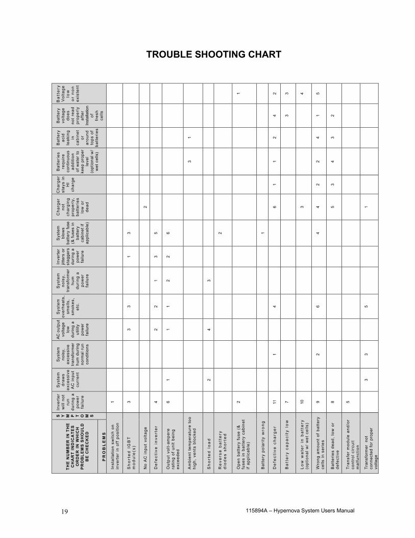
MAINTENANCE AND SERVICE The Self-testing feature of the inverter ensures that the system is tested at least once per month for 5 minutes and once per year for 90 minutes. If there are any problems with the self-tests, the fault log shall indicate which faults occurred. Please see the fault descriptions and troubleshooting guide. A few simple maintenance operations performed periodically will help ensure many years of trouble-free operation. Battery terminals should be checked for tightness and corrosion. If severe corrosion is evident, maintenance is required to correct this situation. Since the unit depends on unrestricted airflow for cooling of power handling components, it is important to keep the air vents free of any obstruction. If the environment tends to be extremely dusty, occasionally blow away any accumulation of dust on components. Please follow the shutdown procedure before cleaning. CAUTION: Follow the shutdown procedure (See Chapter 3) before cleaning. An authorized technician only should perform Service!
Table 7.1 Preventive Maintenance Schedule
SERVICE TO PERFORM: PERFORM SERVICE EVERY:
3 MONTHS 6 MONTHS 12 MONTHS 1. TEST UNIT: NOTE: Perform manual test only when critical load is connected but not required. ----- Output voltage should be present. ----- Confirm operations of front panel indicators.
X
2. INSPECT BATTERIES: ----- All connections are tight. ----- Connections have no corrosion. (Clean if necessary).
X
CLEAN UNIT: NOTE: Unit must be shut down during this service. ----- Inspect air vents and clean if necessary. ----- Clean excessive dust from inside cabinet(s). ----- Clean excessive dust from fan(s).
X
"X" Indicates when to perform service. Lines below the "X" are for the date of service.
115894A – Hypernova System Users Manual 19
TROUBLE SHOOTING CHART
Ba
tte
ry
Vol
tage
lo
w
or
no
n
exis
tent
1 2 3 4 5
Bat
tery
vo
ltage
do
es
not
read
pr
oper
ly
afte
r In
stal
latio
n of
fr
esh
cells
4 3 1 2
Bat
tery
ac
id
leak
ing
in
ca
bine
t or
ar
ound
to
ps o
f ba
tter
ies
1 2 4 3
Bat
teri
es
requ
ire
cont
inuo
us
addi
tion
of
wat
er to
ke
ep p
rope
r le
vel
(opt
iona
l w/
wet
cel
ls)
3 1 2 4
Cha
rger
st
ays
in
HI
char
ge
1 2 3
Cha
rger
no
t ch
argi
ng
prop
erly
, ba
tter
ies
lo
w o
r de
ad
2 6 3 4 5 1
Sys
tem
bl
ows
ba
ttery
fuse
(&
fuse
s in
ba
ttery
ca
bine
t if
appl
icab
le)
3 5 6 2 1 4
Inve
rter
jit
ters
or
stag
gers
du
ring
a po
wer
fa
ilure
1 3 2
Sys
tem
no
isy,
tr
ansf
orm
er
hum
du
ring
a
pow
er
failu
re
1 2 3
Sys
tem
ov
erhe
ats,
sm
ells
, sm
okes
, et
c.
3 2 1 4 6 5
AC o
utpu
t vo
ltage
lo
w
durin
g a
utili
ty
pow
er
failu
re
3 2 1 4
Sys
tem
no
isy,
ex
cess
ive
tran
sfor
mer
hu
m d
urin
g no
rmal
run
co
nditi
ons
1 2 3
Sys
tem
dr
aws
exce
ssiv
e
AC
inpu
t cu
rren
t
1 2 3
Inve
rter
w
ill n
ot
run
du
ring
a
pow
er
failu
re
1 3 4 6 2 11
7 10
9 8 5
S Y M P T O M S
Inst
alla
tion
switc
h on
in
vert
er in
off
pos
ition
Sh
ort
ed
IG
BT
m
od
ule
(s)
No
AC
inpu
t vo
ltage
De
fect
ive
in
vert
er
Out
put
volt-
ampe
re
ratin
g of
uni
t be
ing
exce
eded
Am
bien
t te
mpe
ratu
re t
oo
high
, ve
nts
bloc
ked
Sh
ort
ed
lo
ad
Re
vers
e b
att
ery
d
iod
es
sho
rte
d
Ope
n ba
tter
y fu
se (
&
fuse
s in
bat
tery
cab
inet
if
appl
icab
le)
Bat
tery
pol
arity
wro
ng
De
fect
ive
ch
arg
er
Ba
tte
ry c
ap
aci
ty l
ow
Lo
w w
ate
r in
ba
tte
ry
(opt
iona
l w/
wet
cel
ls)
Wro
ng a
mou
nt o
f ba
tter
y ce
lls in
ser
ies
Bat
teri
es d
ead,
low
or
defe
ctiv
e
Tra
nsfe
r m
odul
e an
d/or
co
ntro
l cir
cuit
mal
func
tion
Tran
sfor
mer
not
co
nnec
ted
for
prop
er
volta
ge
TH
E N
UM
BE
R I
N T
HE
C
HA
RT
IND
ICA
TES
O
RD
ER
IN
WH
ICH
P
RO
BLE
MS
SH
OU
LD
BE
CH
EC
KE
D
PR
OB
LE
MS
115894A – Hypernova System Users Manual 20
RETURN MATERIAL AUTHORIZATION (RMA) POLICY No return material is accepted without written "Return Material Authorization"(RMA). An RMA number is obtainable by contacting the Field Service Department. Every effort will be made to correct problems over the phone before a RMA is granted or a service trip made. Cooperation will save both time and expense for customer and manufacturer. If it is deemed necessary to return material, the RMA number must appear on shipping labels, packing slips, and bills of lading. OUT OF WARRANTY REPAIR CHARGES AND LABOR Contact Field service for current parts and labor rates. A minimum rate will be assessed. The manufacturer will not proceed with repairs of an out of warranty unit until authorization in the form of a purchase order is received from the customer. The unit for repair must be returned prepaid with an RMA number on the carton. For travel to the job site, a quote "Not to Exceed" estimate will be given. A purchase order to cover that amount is required before a trip to the job site is made.
115894A – Hypernova System Users Manual 21
LIMITED WARRANTY The parts and on-site labor for the electronics portion of this equipment are warranted against defects in workmanship and material for a period of one year from time of shipment, but in no case will this warranty be valid if installation of equipment is not accomplished within 180 days from date of shipment. Batteries cannot be disconnected from the unit for long periods (180 days) or they will not be able to charge, creating malfunction of both batteries and/or electronics and thereby voiding the warranty. Systems ordered with "Heavy Lead" batteries over 25 Ah have a one-year unconditional battery warranty with an additional prorated warranty contingent upon timely return of warranty registration card and the terms called out in the particular battery warranty sheet. See individual battery warranty policy. The warranty does not cover damage caused by abuse, improper environmental conditions, shipping damage, improper electronics and/or battery installation, unauthorized modifications, service by unauthorized personnel, transportation of damaged equipment, or acts of war. Damage due to lack of maintenance (where applicable) or damage resulting from installation in areas with other than normal temperatures are not covered. See the battery warranty policy for details, as adverse environmental conditions reduce battery life and void the warranty. Replacement of fuses, pilot lamps, and/or contractor labor is not included in warranty. Damage do to acts of nature, such as, but not limited to, lightning, flooding, explosions, and earthquakes, are not covered. The warranty is limited to the repair and/or replacement of parts and/or units that upon examination at our factory and/or job site are determined to be defective and in our judgment are subject to repair or replacement. All such repair shall be manufacturer's exclusive remedy. All such units are identified by a date code, part number and serial number. TO THE EXTENT ALLOWED BY LAW, MANUFACTURER DISCLAIMS ALL OTHER WARRANTIES, EXPRESS OR IMPLIED, INCLUDING, BUT NOT LIMITED TO, AND LEED WARRANTIES OR MERCHANT ABILITY OR FITNESS FOR A PARTICULAR PURPOSE, AND ANY IMPLIED WARRANTY OF MERCHANT ABILITY OR FITNESS FOR A PARTICULAR PURPOSE ON PRODUCT IS LIMITED IN DURATION TO THE DURATION OF THIS WARRANTY. TO THE EXTENT ALLOWED BY LAW, THE MANUFACTURER SHALL NOT BE LIABLE FOR ANY SPECIAL, INCIDENTAL, OR CONSEQUENTIAL DAMAGES INCLUDING, BUT NOT LIMITED TO, LOSS OF PROFITS, INJURIES TO PROPERTY, LOSS OF USE OF THE PRODUCT OR ANY ASSOCIATED EQUIPMENT. Special on-site extended warranties are also available upon request. The warranty period may be adjusted because of special circumstances, but only by arrangement with the manufacturer at the time of purchase. All in or out of warranty repaired material or replacement units/parts carry a 90-day new part guarantee. Return of your original repaired component or unit is not guaranteed. This limited warranty is for the 48 contiguous states. For international warranty information, call the Field Service Department. See telephone number in front of manual. The standard warranty can be extended and renewed for a nominal fee. Please contact the factory for pricing information.