FIRST BTU BTU RECOVERY APPROX. MODEL GALLON HOUR ENERGY INPUT INPUT 90ºF RISE DRAFT SHIPPING NUMBER CAPACITY RATING FACTOR NATURAL PROPANE GALLONS A B C D E F *G *H HOOD WEIGHT GALLONS GAS GAS PER HR. OUTLET (LBS)
Recovery capacities based on actual performance tests.Water connection is 3/4” on all modelsAll models approved for installation from sea level to 10,100 ft. elevation.Dimensions and specifications subject to change without notice in accordance with our policy of continuous product improvement.
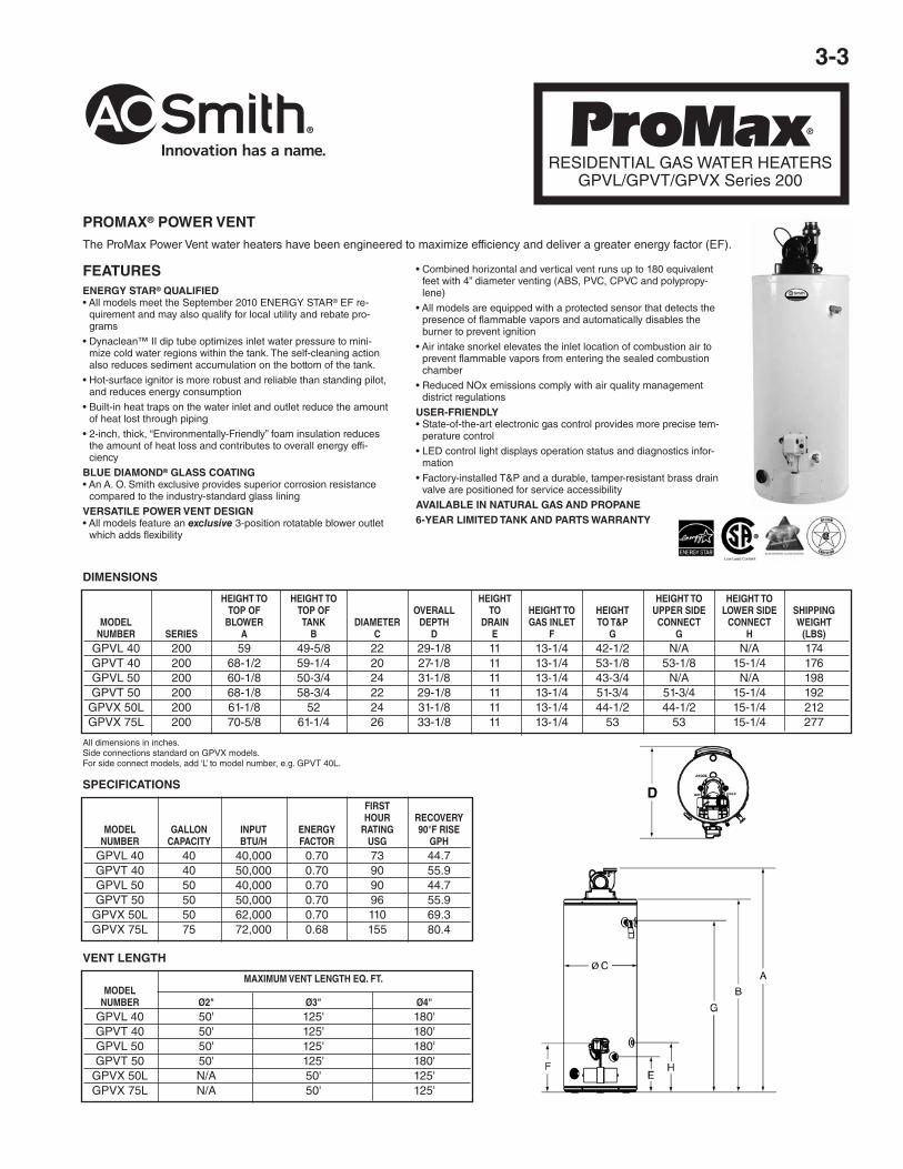
DIMENSIONS IN INCHES
FLAMMABLE VAPOR IGNITION RESISTANT (FVIR) WATER HEATERS
A. O. Smith FVIR design meets the American National Standards Institute standards (ANSIZ21.10.1-CSA 4.1) that deal with the accidental or unintended ignition of flammable vapors, such as thoseemitted by gasoline.
Features a sealed combustion chamber with intake air filter and a flame arrestor built into the water heater base. In addition, a thermal cutoff (TCO) device, is designed to shut off gas flow to theburner and pilot if poor combustion is detected.
INTELLIGENT CONTROL LOGIC*• The internal microprocessor provides enhanced operating parameters and
tighter differentials for precise sensing and faster heating response to optimizeperformance.
• Uses a thermopile to generate the power needed to operate the electronic gascontrol without requiring an external power source.
• The electronic gas control incorporates an LED status indicator that monitorssystem operation and service diagnostics.
• *Not available on 60,000 BTU input models (GCRX-50).GREEN CHOICE® GAS BURNER• Patented eco-friendly burner design reduces NOx emissions by up to 33% and
complies with Low-NOx emission requirements of less than 40 ng/J.DYNACLEAN™ DIFFUSER DIP TUBE• Reduces lime and sediment buildup and maximizes hot water output. Made
from long-lasting PEX cross-linked polymer.COREGARD™ ANODE ROD• Our anode rods have a stainless steel core that extends the life of the anode
rod allowing superior tank protection far longer than standard anode rods.PUSH-BUTTON PIEZO IGNITOR• Makes lighting the pilot fast and easy with one-hand push-button spark ignition.HEAT TRAP NIPPLES• Factory-installed for faster installation.BLUE DIAMOND® GLASS COATING• Provides superior corrosion resistance compared to industry standard glass lin-
ing.ENHANCED-FLOW BRASS DRAIN VALVE• Our residential water heaters have a solid brass, tamper resistant, enhanced-
flow, ball type, drain valve.• Uses a standard female hose fitting that allows for fast and easy draining during
maintenance.• Designed for easy operation, this valve includes an integral screwdriver slot that
features a 1/4 turn (open/close) radius, which not only permits full straight-through water flow but also a quick and positive shut off.
CODE COMPLIANCE• Meets UBC, CEC and HUD National Codes.• Meets the thermal efficiency and standby loss requirements of the U. S. Depart-
ment of Energy and current edition of ASHRAE/IENSA 90.1.• Complies with the Federal Energy Conservation Standards effective April 16,
2015, in accordance with the Energy Policy and Conservation Act, (EPCA), asamended.
HIGH ENERGY FACTORS• Eco-Friendly non-CFC foam insulation, external heat traps and specially de-
signed combustion chamber combine to produce a high Energy Factor for maxi-mum savings on operating costs.
CSA CERTIFIED AND ASME RATED T&P RELIEF VALVEMAXIMUM HYDROSTATIC WORKING PRESSURE 150 PSIDESIGN-CERTIFIED BY CSA INTERNATIONAL• Certified at 300 PSI test pressure and 150 PSI working pressure. Listed accord-
ing to ANSI Z21.10.1-CSA 4.1 standards governing storage tank-type gas waterheaters.
6-YEAR LIMITED TANK AND PARTS WARRANTY• For complete information, consult written warranty or go to hotwater.com
3-2
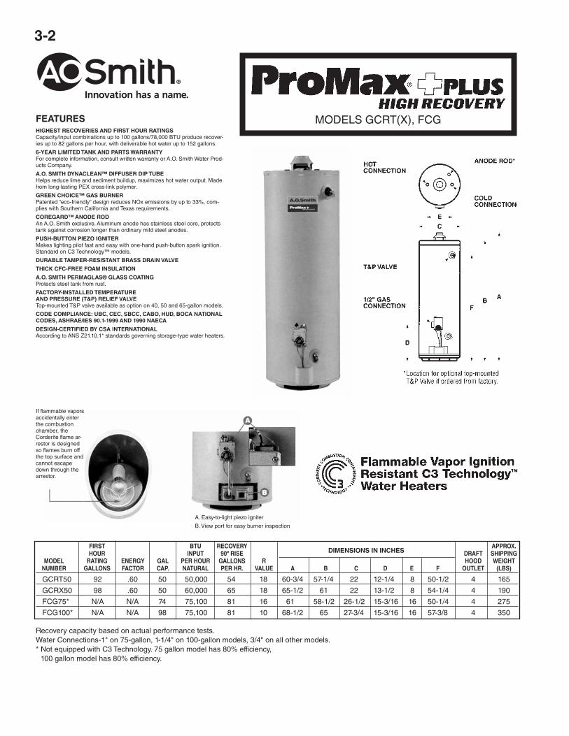
FEATURESHIGHEST RECOVERIES AND FIRST HOUR RATINGSCapacity/input combinations up to 100 gallons/78,000 BTU produce recover-ies up to 82 gallons per hour, with deliverable hot water up to 152 gallons.
6-YEAR LIMITED TANK AND PARTS WARRANTYFor complete information, consult written warranty or A.O. Smith Water Prod-ucts Company.
A.O. SMITH DYNACLEAN™ DIFFUSER DIP TUBEHelps reduce lime and sediment buildup, maximizes hot water output. Madefrom long-lasting PEX cross-link polymer.
GREEN CHOICE™ GAS BURNERPatented “eco-friendly” design reduces NOx emissions by up to 33%, com-plies with Southern California and Texas requirements.
COREGARD™ ANODE RODAn A.O. Smith exclusive. Aluminum anode has stainless steel core, protectstank against corrosion longer than ordinary mild steel anodes.
PUSH-BUTTON PIEZO IGNITERMakes lighting pilot fast and easy with one-hand push-button spark ignition.Standard on C3 Technology™ models.
DURABLE TAMPER-RESISTANT BRASS DRAIN VALVE
THICK CFC-FREE FOAM INSULATION
A.O. SMITH PERMAGLAS® GLASS COATINGProtects steel tank from rust.
FACTORY-INSTALLED TEMPERATUREAND PRESSURE (T&P) RELIEF VALVETop-mounted T&P valve available as option on 40, 50 and 65-gallon models.
DESIGN-CERTIFIED BY CSA INTERNATIONALAccording to ANS Z21.10.1* standards governing storage-type water heaters.
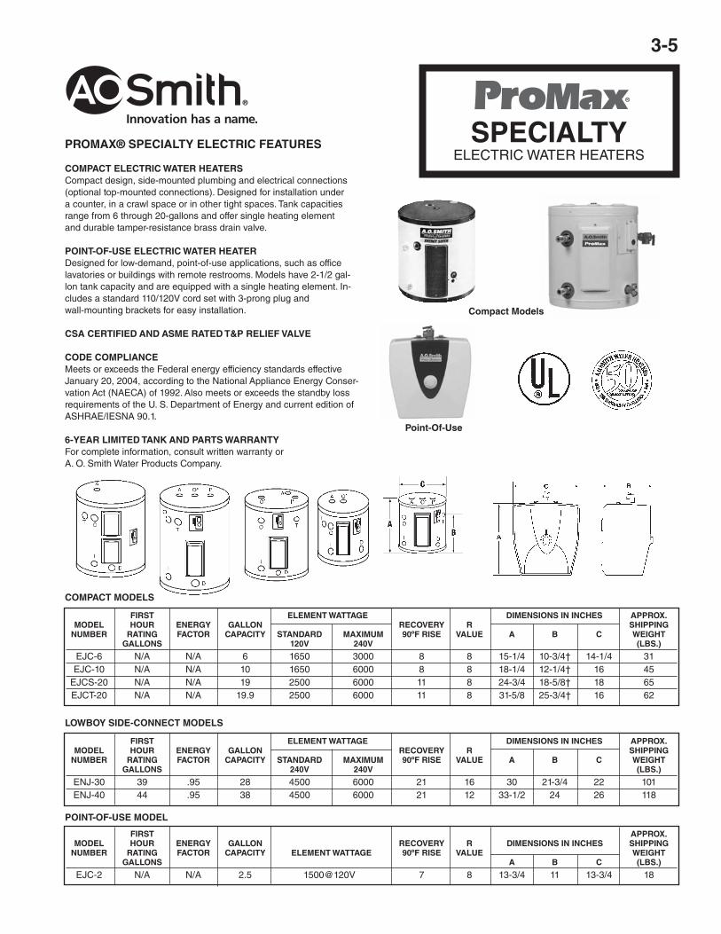
If flammable vaporsaccidentally enterthe combustionchamber, theCorderite flame ar-restor is designedso flames burn offthe top surface andcannot escapedown through thearrestor.
A. Easy-to-light piezo igniter
B. View port for easy burner inspection
FIRST BTU RECOVERY APPROX. HOUR INPUT 90º RISE DRAFT SHIPPING MODEL RATING ENERGY GAL PER HOUR GALLONS R HOOD WEIGHT NUMBER GALLONS FACTOR CAP. NATURAL PER HR. VALUE A B C D E F OUTLET (LBS)
Recovery capacity based on actual performance tests.Water Connections-1" on 75-gallon, 1-1/4" on 100-gallon models, 3/4" on all other models.* Not equipped with C3 Technology. 75 gallon model has 80% efficiency,
100 gallon model has 80% efficiency.
MODELS GCRT(X), FCG
3-3
All dimensions in inches.Side connections standard on GPVX models.For side connect models, add ‘L’ to model number, e.g. GPVT 40L.
FEATURESENERGY STAR® QUALIFIED• All models meet the September 2010 ENERGY STAR® EF re-
quirement and may also qualify for local utility and rebate pro-grams
• Dynaclean™ II dip tube optimizes inlet water pressure to mini-mize cold water regions within the tank. The self-cleaning actionalso reduces sediment accumulation on the bottom of the tank.
• Hot-surface ignitor is more robust and reliable than standing pilot,and reduces energy consumption
• Built-in heat traps on the water inlet and outlet reduce the amountof heat lost through piping
• 2-inch, thick, “Environmentally-Friendly” foam insulation reducesthe amount of heat loss and contributes to overall energy effi-ciency
BLUE DIAMOND® GLASS COATING• An A. O. Smith exclusive provides superior corrosion resistance
compared to the industry-standard glass lining
VERSATILE POWER VENT DESIGN• All models feature an exclusive 3-position rotatable blower outlet
which adds flexibility
• Combined horizontal and vertical vent runs up to 180 equivalentfeet with 4” diameter venting (ABS, PVC, CPVC and polypropy-lene)
• All models are equipped with a protected sensor that detects thepresence of flammable vapors and automatically disables theburner to prevent ignition
• Air intake snorkel elevates the inlet location of combustion air toprevent flammable vapors from entering the sealed combustionchamber
• Reduced NOx emissions comply with air quality managementdistrict regulations
USER-FRIENDLY• State-of-the-art electronic gas control provides more precise tem-
perature control
• LED control light displays operation status and diagnostics infor-mation
• Factory-installed T&P and a durable, tamper-resistant brass drainvalve are positioned for service accessibility
AVAILABLE IN NATURAL GAS AND PROPANE6-YEAR LIMITED TANK AND PARTS WARRANTY
RESIDENTIAL GAS WATER HEATERSGPVL/GPVT/GPVX Series 200
HEIGHT TO HEIGHT TO HEIGHT HEIGHT TO HEIGHT TO TOP OF TOP OF OVERALL TO HEIGHT TO HEIGHT UPPER SIDE LOWER SIDE SHIPPING MODEL BLOWER TANK DIAMETER DEPTH DRAIN GAS INLET TO T&P CONNECT CONNECT WEIGHT NUMBER SERIES A B C D E F G G H (LBS) GPVL 40 200 59 49-5/8 22 29-1/8 11 13-1/4 42-1/2 N/A N/A 174 GPVT 40 200 68-1/2 59-1/4 20 27-1/8 11 13-1/4 53-1/8 53-1/8 15-1/4 176 GPVL 50 200 60-1/8 50-3/4 24 31-1/8 11 13-1/4 43-3/4 N/A N/A 198 GPVT 50 200 68-1/8 58-3/4 22 29-1/8 11 13-1/4 51-3/4 51-3/4 15-1/4 192 GPVX 50L 200 61-1/8 52 24 31-1/8 11 13-1/4 44-1/2 44-1/2 15-1/4 212 GPVX 75L 200 70-5/8 61-1/4 26 33-1/8 11 13-1/4 53 53 15-1/4 277
DIMENSIONS
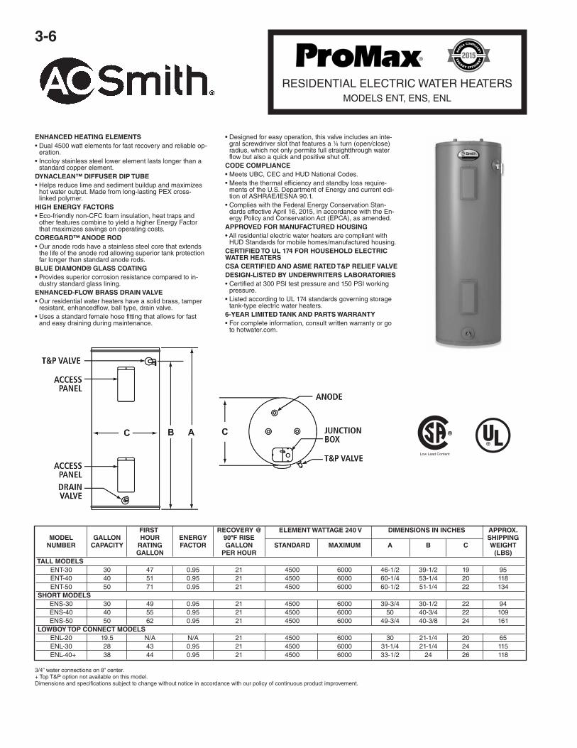
PROMAX® POWER VENTThe ProMax Power Vent water heaters have been engineered to maximize efficiency and deliver a greater energy factor (EF).
MAXIMUM VENT LENGTH EQ. FT. MODEL NUMBER Ø2" Ø3" Ø4" GPVL 40 50' 125' 180' GPVT 40 50' 125' 180' GPVL 50 50' 125' 180' GPVT 50 50' 125' 180' GPVX 50L N/A 50' 125' GPVX 75L N/A 50' 125'
VENT LENGTH
3-4
VERTEX™
90% EFFICIENCY POWER VENTWATER HEATERMODEL GPHE-50
NATURAL GAS PROPANE GAS A B C D E F G Vent GPH GPH Hgt. to Side Side Hgt. Gas Approx. Gal. Pipe 90 º 90 º Top of Out- In- Drain Inlet/ Ship.
Model Cap. Dia. Input Rise Input Rise Hgt. Jacket let Let Valve Diameter Wt.GPHE-50 50 3" 76,000 92 76,000 92 71 68-5/8 52 21 9-1/8 12 22 210
FEATURESHELICAL INTERNAL HEAT EXCHANGER• Positioned in the center of the tank, surrounded by water to
virtually eliminate radiant heatloss from the chamber
• Achieves 90% thermal efficiency which saves money on op-erating costs compared to a standard 78% efficient gaswater heater
POWER VENTS USING PVC PIPE• Combined vertical and horizontal vent runs terminating
through an outside wall, using Schedule 40 PVC
• 2" pipe, vents up to 25 equivalent feet
• 3" pipe, vents up to 65 equivalent feet
• 4" pipe, vents up to 128 equivalent feet
MODULAR BLOWER• Equipped with 120 volt, 60 Hz electrical system (rating 5
amps or less), 6-foot cord with standard 3-prong connector
• 2" PVC pipe, elbows and condensate drain supplied to con-nect heat exchanger outlet to blower
• PVC Vent Attenuation Assembly (VAA) supplied
SIDE-MOUNTED HOT AND COLD RECIRCULATING TAPS• Allows Vertex to be installed as part of combination space
heating/water heating applications or any system requiringa recirculating hot water loop, including radiant floor heatingINTELLI-VENT™**
GAS CONTROL• Equipped with nearly indestructible silicon nitride hot surface
ignitor
• Advanced electronics for more precise control of water tem-perature and easy to understand system diagnostics
COMMERCIAL GRADE GLASS LINING• A. O. Smith PermaGlas® Ultra Coat™ process provides su-
perior protection against corrosion
• Protects all interior tank surfaces including inside and out-side of helical heat exchanger
TWO HEAVY-DUTY ANODE RODS• Provide maximum protection against corrosionGREEN
CHOICE® GAS BURNER
• Patented “Eco-Friendly” design reduces NOx emissions byup to 33%
CERTIFIED AND ASME RATED T&P RELIEF VALVEMAXIMUM HYDROSTATIC WORKING PRESSURE: 150 PSI®Residential Gas Water Heaters• Spiral heat exchanger reduces scale and sediment fromforming on water-side surface, which can reduce energy effi-ciency over time
®
MAXIMUM VENT DISTANCE MODEL BTU (Total Equivalent Feet) NUMBER INPUT 2" Pipe 3" Pipe 4" Pipe GPHE-50 76,000 25’ 65' 128'
If flammable vaporsaccidentally enterthe combustionchamber, theCorderite flame ar-restor is designedso flames burn offthe top surface andcannot escapedown through thearrestor.
3-5
SPECIALTYELECTRIC WATER HEATERS
Compact Models
PROMAX® SPECIALTY ELECTRIC FEATURES
COMPACT ELECTRIC WATER HEATERSCompact design, side-mounted plumbing and electrical connections(optional top-mounted connections). Designed for installation undera counter, in a crawl space or in other tight spaces. Tank capacitiesrange from 6 through 20-gallons and offer single heating elementand durable tamper-resistance brass drain valve.
POINT-OF-USE ELECTRIC WATER HEATERDesigned for low-demand, point-of-use applications, such as officelavatories or buildings with remote restrooms. Models have 2-1/2 gal-lon tank capacity and are equipped with a single heating element. In-cludes a standard 110/120V cord set with 3-prong plug andwall-mounting brackets for easy installation.
CSA CERTIFIED AND ASME RATED T&P RELIEF VALVE
CODE COMPLIANCEMeets or exceeds the Federal energy efficiency standards effectiveJanuary 20, 2004, according to the National Appliance Energy Conser-vation Act (NAECA) of 1992. Also meets or exceeds the standby lossrequirements of the U. S. Department of Energy and current edition ofASHRAE/IESNA 90.1.
6-YEAR LIMITED TANK AND PARTS WARRANTYFor complete information, consult written warranty orA. O. Smith Water Products Company.
FIRST ELEMENT WATTAGE DIMENSIONS IN INCHES APPROX. MODEL HOUR ENERGY GALLON RECOVERY R SHIPPING NUMBER RATING FACTOR CAPACITY STANDARD MAXIMUM 90ºF RISE VALUE A B C WEIGHT GALLONS 120V 240V (LBS.)
FIRST ELEMENT WATTAGE DIMENSIONS IN INCHES APPROX. MODEL HOUR ENERGY GALLON RECOVERY R SHIPPING NUMBER RATING FACTOR CAPACITY STANDARD MAXIMUM 90ºF RISE VALUE A B C WEIGHT GALLONS 240V 240V (LBS.)
FIRST APPROX. MODEL HOUR ENERGY GALLON RECOVERY R DIMENSIONS IN INCHES SHIPPING NUMBER RATING FACTOR CAPACITY ELEMENT WATTAGE 90ºF RISE VALUE WEIGHT GALLONS A B C (LBS.)
FIRST RECOVERY @ ELEMENT WATTAGE 240 V DIMENSIONS IN INCHES APPROX. MODEL GALLON HOUR ENERGY 90ºF RISE SHIPPING NUMBER CAPACITY RATING FACTOR GALLON STANDARD MAXIMUM A B C WEIGHT GALLON PER HOUR (LBS)TALL MODELS ENT-30 30 47 0.95 21 4500 6000 46-1/2 39-1/2 19 95 ENT-40 40 51 0.95 21 4500 6000 60-1/4 53-1/4 20 118 ENT-50 50 71 0.95 21 4500 6000 60-1/2 51-1/4 22 134SHORT MODELS ENS-30 30 49 0.95 21 4500 6000 39-3/4 30-1/2 22 94 ENS-40 40 55 0.95 21 4500 6000 50 40-3/4 22 109 ENS-50 50 62 0.95 21 4500 6000 49-3/4 40-3/8 24 161LOWBOY TOP CONNECT MODELS ENL-20 19.5 N/A N/A 21 4500 6000 30 21-1/4 20 65 ENL-30 28 43 0.95 21 4500 6000 31-1/4 21-1/4 24 115 ENL-40+ 38 44 0.95 21 4500 6000 33-1/2 24 26 118
3/4” water connections on 8” center.+ Top T&P option not available on this model.Dimensions and specifications subject to change without notice in accordance with our policy of continuous product improvement.
RESIDENTIAL ELECTRIC WATER HEATERSMODELS ENT, ENS, ENL
ENHANCED HEATING ELEMENTS• Dual 4500 watt elements for fast recovery and reliable op-
eration.• Incoloy stainless steel lower element lasts longer than a
standard copper element.DYNACLEAN™ DIFFUSER DIP TUBE• Helps reduce lime and sediment buildup and maximizes
hot water output. Made from long-lasting PEX cross-linked polymer.
HIGH ENERGY FACTORS• Eco-friendly non-CFC foam insulation, heat traps and
other features combine to yield a higher Energy Factorthat maximizes savings on operating costs.
COREGARD™ ANODE ROD• Our anode rods have a stainless steel core that extends
the life of the anode rod allowing superior tank protectionfar longer than standard anode rods.
BLUE DIAMOND® GLASS COATING• Provides superior corrosion resistance compared to in-
dustry standard glass lining.ENHANCED-FLOW BRASS DRAIN VALVE• Our residential water heaters have a solid brass, tamper
resistant, enhancedflow, ball type, drain valve.• Uses a standard female hose fitting that allows for fast
and easy draining during maintenance.
• Designed for easy operation, this valve includes an inte-gral screwdriver slot that features a ¼ turn (open/close)radius, which not only permits full straightthrough waterflow but also a quick and positive shut off.
CODE COMPLIANCE• Meets UBC, CEC and HUD National Codes.• Meets the thermal efficiency and standby loss require-
ments of the U.S. Department of Energy and current edi-tion of ASHRAE/IESNA 90.1.
• Complies with the Federal Energy Conservation Stan-dards effective April 16, 2015, in accordance with the En-ergy Policy and Conservation Act (EPCA), as amended.
APPROVED FOR MANUFACTURED HOUSING• All residential electric water heaters are compliant with
HUD Standards for mobile homes/manufactured housing.CERTIFIED TO UL 174 FOR HOUSEHOLD ELECTRICWATER HEATERSCSA CERTIFIED AND ASME RATED T&P RELIEF VALVEDESIGN-LISTED BY UNDERWRITERS LABORATORIES• Certified at 300 PSI test pressure and 150 PSI working
pressure.• Listed according to UL 174 standards governing storage
tank-type electric water heaters.6-YEAR LIMITED TANK AND PARTS WARRANTY• For complete information, consult written warranty or go
to hotwater.com.
3-7
COMMERCIALELECTRIC WATER HEATERS
Not available with top mounted T&P valve option. Inlet and outlet connections: 3/4”
GLASSLINED TANKTank interior is coated with glass specially designedby A. O. Smith for water heater use.
STANDARD VOLTAGESThe standard voltage is 240V single phase.
TOP MOUNTED RECESSEDJUNCTION BOXCONTROLSThermostat is adjustable through a range of 120º to181ºF with a manual reset high temperature cutoff.The heater is wired for non-simultaneous singlephase operation.
COREGARD™ ANODE RODOur anode rods have a stainless steel corethat extends the life of the anode rod allowingsuperior tank protection for longer than standardanode rods.
MAXIMUM WORKING PRESSURE150 PSIFACTORY INSTALLED CSACERTIFIED AND ASME RATEDTEMPERATURE AND PRESSURERELIEF VALVECERTIFIED TO UL 1453 FORCOMMERCIAL ELECTRIC WATERHEATERSCOMPLIANCEMeets the standby loss requirements of theU.S. Department of Energy and current edition ofASHRAE/IES 90.1.
• For complete information consult the writtenwarranty or hotwater.com.
LIGHT-SERVICE COMMERCIAL ELECTRIC WATER HEATERSDesigned for light duty commercial applications with intermittent hot water loads.
Model Gallon Standard Element Dimensions in Inches Approx. Shipping Number Capacity Wattage 240 VAC A B C D Weight (lbs) Diameter
LTE 66D 66 4500 60-1/4 53 22 8 146
LTE 80D 80 4500 60-1/2 52-1/4 24 8 175
LTE 120D 119 4500 61-1/2 54-1/2 28 8 268
PRODUCT SPECIFICATIONS
3-8
FEATURESAll models comply with ASHRAE/IES 90.1b-1992.
GLASS-LINED TANK — Assures years of rust-free clean hot water.
FULLY AUTOMATIC CONTROLS WITH SAFETY SHUTOFF — Accurate, dependable control system requires noelectric connections. Fixed automatic gas shutoff device for added safety. Not recommended for 180°F sanitizing. UseModels BTC-80 & BTC-100 for 180°F sanitizing.
HEAVY GAUGE STEEL JACKET — Finished with baked enamel over bonderized undercoat.
CERTIFICATION — Units are design certified by the American Gas Association (Canadian Gas Association for unitsbuilt in Canada). Meets rigid requirements of the National Sanitation Foundation when equipped with leg kit. Certifiedfor installation on combustible flooring.
EASY TO INSTALL — Completely factory assembled. Only gas, water and vent connections need be made. All con-nections are located in front and top of heaters for ease of installation and service.
DRAFT DIVERTER — Low profile diverter furnished as standard equipment.
MAXIMUM WORKING PRESSURE — 150 psi.
MAXIMUM GAS INLET PRESSURE — 14" W.C.
HANDHOLE CLEANOUT — On 75 and 100 gallon models. Allows easy tank cleaning.
OTHER FEATURES• Built-in gas filter and integral dirt leg (propane only) • Anodic protection • Equipped with gas pressure regulator • In-tegral automatic gas shutoff system prevents excessive water temperature • Factory installed A.G.A./ASME rated tem-perature and pressure relief valve.
CONSERVATIONIST®
TANK-TYPE WATER HEATERSBT-65, 80 & 100
LIMITED WARRANTY OUTLINE
If the tank should leak any time during the first three years, underthe terms of the warranty, A. O. Smith will furnish a replacementheater; installation, labor, handling and local delivery extra. THISOUTLINE IS NOT A WARRANTY. For complete information,consult the written warranty or A. O. Smith Water Products Com-pany.
Warranty does not apply to product installed outside of theUnited States of America or its territorial possessions andCanada.
FOR UNITSBUILT IN USA
NOTE: To compensate for the effects of high altitude areas above 2000 feet, recovery capacity should be reduced approximately 4% for every 1000feet above sea level.
Capacity ratings are at 75% thermal efficiency (except as noted).
Approx. Type Input Gal. of Rating Temperature Rise - Degrees F - Gallons Per Hour
Approx. Inlet Ship. Wt. Model A B C D E F G H J Outlet (Lbs.) BT65 64-3/4 59-7/8 20-1/4 23-3/8 15-5/8 4 8 11-1/2 11-3/4 3/4 165 BT80 61-1/2 58-1/2 25-1/2 28-1/2 15-3/16 4 16 14 11-15/16 1 291 BT100 68-3/4 66-1/2 26-1/2 29-3/4 15-3/16 4 16 14-1/2 11-15/16 1-1/4 366
ALL DIMENSIONS IN INCHES
3-9
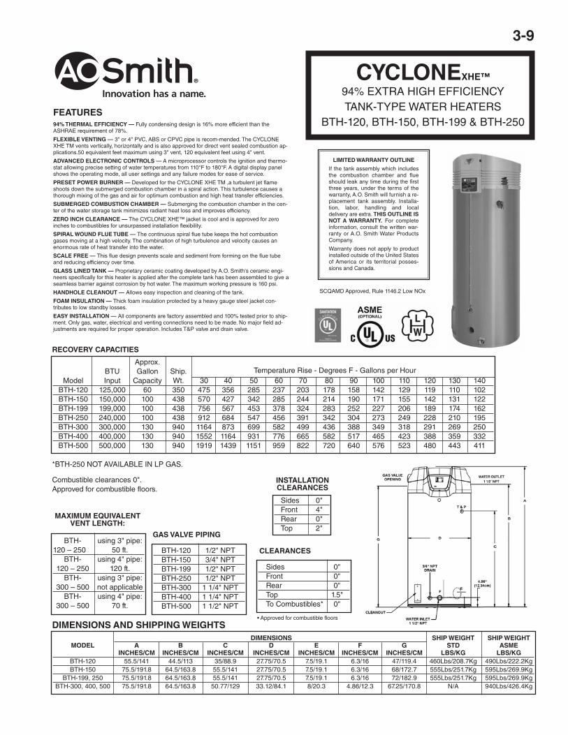
CYCLONEXHE™
94% EXTRA HIGH EFFICIENCYTANK-TYPE WATER HEATERS
BTH-120, BTH-150, BTH-199 & BTH-250
SCQAMD Approved, Rule 1146.2 Low NOx
LIMITED WARRANTY OUTLINE
If the tank assembly which includesthe combustion chamber and flueshould leak any time during the firstthree years, under the terms of thewarranty, A.O. Smith will furnish a re-placement tank assembly. Installa-tion, labor, handling and localdelivery are extra. THIS OUTLINE ISNOT A WARRANTY. For completeinformation, consult the written war-ranty or A.O. Smith Water ProductsCompany.
Warranty does not apply to productinstalled outside of the United Statesof America or its territorial posses-sions and Canada.
INSTALLATIONCLEARANCES
Sides 0" Front 4" Rear 0" Top 2"
Combustible clearances 0".Approved for combustible floors.
DIMENSIONS SHIP WEIGHT SHIP WEIGHT MODEL A B C D E F G STD ASME INCHES/CM INCHES/CM INCHES/CM INCHES/CM INCHES/CM INCHES/CM INCHES/CM LBS/KG LBS/KG BTH-120 55.5/141 44.5/113 35/88.9 27.75/70.5 7.5/19.1 6.3/16 47/119.4 460Lbs/208.7Kg 490Lbs/222.2Kg BTH-150 75.5/191.8 64.5/163.8 55.5/141 27.75/70.5 7.5/19.1 6.3/16 68/172.7 555Lbs/251.7Kg 595Lbs/269.9Kg BTH-199, 250 75.5/191.8 64.5/163.8 55.5/141 27.75/70.5 7.5/19.1 6.3/16 72/182.9 555Lbs/251.7Kg 595Lbs/269.9Kg BTH-300, 400, 500 75.5/191.8 64.5/163.8 50.77/129 33.12/84.1 8/20.3 4.86/12.3 67.25/170.8 N/A 940Lbs/426.4Kg
DIMENSIONS AND SHIPPING WEIGHTS
Sides 0" Front 0" Rear 0" Top 1.5" To Combustibles* 0"
GAS VALVE PIPING BTH- using 3" pipe:120 – 250 50 ft. BTH- using 4" pipe: 120 – 250 120 ft. BTH- using 3" pipe: 300 – 500 not applicable BTH- using 4" pipe: 300 – 500 70 ft.
FEATURES94% THERMAL EFFICIENCY — Fully condensing design is 16% more efficient than theASHRAE requirement of 78%.
FLEXIBLE VENTING — 3" or 4" PVC, ABS or CPVC pipe is recom-mended. The CYCLONEXHE TM vents vertically, horizontally and is also approved for direct vent sealed combustion ap-plications.50 equivalent feet maximum using 3" vent, 120 equivalent feet using 4" vent.
ADVANCED ELECTRONIC CONTROLS — A microprocessor controls the ignition and thermo-stat allowing precise setting of water temperatures from 110°F to 180°F. A digital display panelshows the operating mode, all user settings and any failure modes for ease of service.
PRESET POWER BURNER — Developed for the CYCLONE XHE TM ,a turbulent jet flameshoots down the submerged combustion chamber in a spiral action. This turbulence causes athorough mixing of the gas and air for optimum combustion and high heat transfer efficiencies.
SUBMERGED COMBUSTION CHAMBER — Submerging the combustion chamber in the cen-ter of the water storage tank minimizes radiant heat loss and improves efficiency.
ZERO INCH CLEARANCE — The CYCLONE XHE™ jacket is cool and is approved for zeroinches to combustibles for unsurpassed installation flexibility.
SPIRAL WOUND FLUE TUBE — The continuous spiral flue tube keeps the hot combustiongases moving at a high velocity. The combination of high turbulence and velocity causes anenormous rate of heat transfer into the water.
SCALE FREE — This flue design prevents scale and sediment from forming on the flue tubeand reducing efficiency over time.
GLASS LINED TANK — Proprietary ceramic coating developed by A.O. Smith's ceramic engi-neers specifically for this heater is applied after the complete tank has been assembled to give aseamless barrier against corrosion by hot water. The maximum working pressure is 160 psi.
HANDHOLE CLEANOUT — Allows easy inspection and cleaning of the tank.
FOAM INSULATION — Thick foam insulation protected by a heavy gauge steel jacket con-tributes to low standby losses.
EASY INSTALLATION — All components are factory assembled and 100% tested prior to ship-ment. Only gas, water, electrical and venting connections need to be made. No major field ad-justments are required for proper operation. Includes T&P valve and drain valve.
3-10
THE ELIMINATOR™SELF-CLEANING SYSTEM• Designed to significantly reduce or eliminate buildup of lime, sand and other sediment in-
side the tank
• Reduced sediment buildup helps Master-Fit water heaters maintain their rated energy-ef-ficiency and reduce water heating costs
• Self-cleaning system also helps prolong tank life
BUILT-IN INDUCED DRAFT BLOWER• Produces power-induced draft of makeup air prior to burner ignition
• Provides more efficient control of heat through the fluecollector
• Ideal for installations where negative air pressure is apotential problem
• No draft hood or barometric damper required
RATED AS CATEGORY 1 APPLIANCE• Can be commonly vented with other Category 1 appliances, using standard metal type
“B” vent
PERMAGLAS® ULTRA COATGLASS LINING• A.O. Smith exclusive process provides superior protection against corrosion
• A.O. Smith CoreGard anode rods with stainless steel core provide additional corrosionprotection
THREE WATER CONNECTION OPTIONS• Hot and cold water connections can be made through top, front or rear of water heater
• The Eliminator self-cleaning device operates when cold water is connected through front
INTERMITTENT ELECTRONIC IGNITION• Eliminates standing pilot
• Includes power ON/OFF switch
• Provides flame failure response in less than one second
FACTORY-INSTALLED TEMPERATURE & PRESSURE RELIEF VALVEMAXIMUM HYDROSTATIC WORKINGPRESSURE 160 PSI80% THERMAL EFFICIENCY CODES AND STANDARDS• Design-certified by CSA International, according to to ANSZ21.10.3 standards governing
storage-type water heaters
• Optional ASME construction available
WARRANTY• Three-year limited warranty against tank leaks
• For complete warranty information, consult written warranty shipped with water heater, orcontact A.O. Smith Water Products Company
The Master-Fit® BTR-151 and BTR-201 are designed for installa-tion in “booster” applications, to supply commercial dishwasherswith very high temperature water…usually 180ºF. A booster waterheater is normally used in conjunction with a standard waterheater water delivering hot water at a lower temperature to meetthe non-dishwashing needs of a restaurant or other foodserviceapplication.
Master - FitBOOSTER MODELS
COMMERCIAL WATER HEATERSBTR-151, BTR-201
3-11
DIMENSIONS AND WEIGHT
BTU FIRST INPUT HOUR RECOVERY – GALLONS MODEL GALS. PER RATING PER HOUR AT °F TEMPERATURE RISE NUMBER CAP. HOUR 100°F RISE 40° 100° 140°
BTR-151 32 150,000 167 364 145 104
BTR-201 32 199,000 216 485 194 139
SUGGESTED SPECIFICATIONGas booster water heater(s) shall be A.O. Smith Master-Fit, Model Number ___________________ , with a 32-gallon storage capacity, an input rate of __________________ BTU/HR, _________________ gas, and a recoveryrate of ________ gallons per hour at a ________ degree Fahrenheit temperature rise, and a maximum hydrostaticworking pressure of 160 psi.
Unit(s) shall have a fan-assisted combustion system, providing a power-induced draft of makeup air prior to burner ig-nition.
Unit(s) shall be equipped with intermittent electronic ignition with power on/off switch, which shall provide flamefailure response in less than one second. The burner for the unit(s) shall be easily removable. Unit(s) shall beequipped with a factory-installed temperature and pressure relief valve, and a 2-3/4” x 3-3/4” tank inspection port.
The water heater tank shall be glasslined and protected against premature failure in the following ways:
1. Against electrolytic corrosion by multiple, factory-installed anode rods
2. Against failure due to overheating caused by the buildup of scale, film and other sediment by a self-cleaning de-vice, positioned inside the tank so that it directs the flow of inlet water in such a way that microscopic particles ofprecipitated solids shall be kept in suspension and exhausted from the water heater on that or successive hotwater draws.
Unit(s) shall meet or exceed ASHRAE/IESNA 90.1-1999, and be design certified by CSA International, according toANSZ21.10.3 standards governing storage-type water heaters.
CAPACITY, INPUT AND OUTPUT
DIMENSIONS IN INCHES APPROX. MODEL GAS WATER SHIPPING NUMBER CONN. CONN. WEIGHT A B C D E F G H (LBS.)
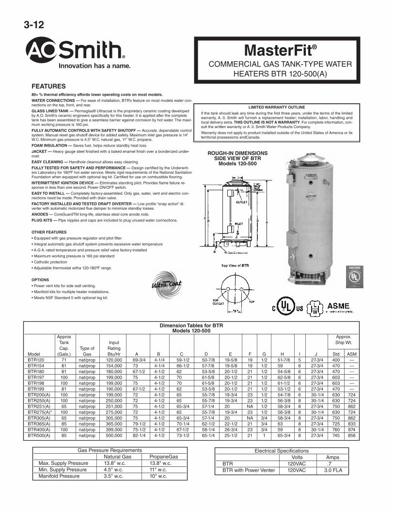
FEATURES80+ % thermal efficiency affords lower operating costs on most models.
WATER CONNECTIONS — For ease of installation, BTR’s feature on most models water con-nections on the top, front, and rear.
GLASS LINED TANK — Permaglas® Ultracoat is the proprietary ceramic coating developedby A.O. Smith’s ceramic engineers specifically for this heater. It is applied after the completetank has been assembled to give a seamless barrier against corrosion by hot water. The maxi-mum working pressure is 160 psi.
FULLY AUTOMATIC CONTROLS WITH SAFETY SHUTOFF — Accurate, dependable controlsystem. Manual reset gas shutoff device for added safety. Maximum inlet gas pressure is 14"W.C. Minimum gas pressure is 4.5" W.C. natural gas, 11" W.C. propane.
FULLY TESTED FOR SAFETY AND PERFORMANCE — Design certified by the Underwrit-ers Laboratory for 180ºF hot water service. Meets rigid requirements of the National SanitationFoundation when equipped with optional leg kit. Certified for use on combustible flooring.
INTERMITTENT IGNITION DEVICE — Eliminates standing pilot. Provides flame failure re-sponse in less than one second. Power ON/OFF switch.
EASY TO INSTALL — Completely factory-assembled. Only gas, water, vent and electric con-nections need be made. Provided with drain valve.
FACTORY INSTALLED AND TESTED DRAFT DIVERTER — Low profile “snap action” di-verter with automatic motorized flue damper to minimize standby losses.
COMMERCIAL GAS TANK-TYPE WATERHEATERS BTR 120-500(A)
LIMITED WARRANTY OUTLINE
If the tank should leak any time during the first three years, under the terms of the limitedwarranty, A. 0. Smith will furnish a replacement heater; installation, labor, handling andlocal delivery extra. THIS OUTLINE IS NOT A WARRANTY. For complete information, con-sult the written warranty or A. 0. Smith Water Products Company.
Warranty does not apply to product installed outside of the United States of Amenca or itsterritorial possessions andCanada.
ROUGH-IN DIMENSIONSSIDE VIEW OF BTR
Models 120-500
Gas Pressure Requirements Natural Gas PropaneGas Max. Supply Pressure 13.8" w.c. 13.8" w.c. Min. Supply Pressure 4.5" w.c. 11" w.c. Manifold Pressure 3.5" w.c. 10" w.c.
Electrical Specifications Volts Amps BTR 120VAC .7 BTR with Power Venter 120VAC 3.0 FLA
3-13
MasterFit®
COMMERCIAL GAS TANK-TYPE WATERHEATERS BTR 120-500(A)
POWER VENTS FOR BTRFEATURESDESIGNED FOR FLEXIBILITY — Easy to install sidewall power vent system. Use these kits where gas is the preferred choice, but conventional vent-ing is costly. Allows conversion from electric to gas or upgrading to units with higher inputs without having to do costly venting system upgrades. Easyto install and wire. Approved for use on all A.O. Smith water heaters listed below. Allows th~ use of smaller diameter vent pipe than allowed with con-ventional venting.
POWERFUL 115 VOLT POWER VENTER — Allows venting up to 100 equivalent feet away. Each model sized for a perfect match with A.O. Smithwater heaters. Power Venters have one or more of the following depending on the heater’s requirements. Built in 24/11 Svolt relay to interface withcontrol systems. Combination 24 volt relay and adjustable post-purge timer control in lieu of relay on some models. Installed diaphragm draft provingswitch. Vibration isolation mount works with common plumber’s strap and helps keep operation quiet. All controls factory mounted and wired for sim-ple installation.
ALUMINUM VENT HOOD — Mounts on outside of wall. Features telescoping vent pipe connection sleeve, rust free construction, outside wall con-densate shield, 1 airspace provides clearance forcombustibles, special heat shield protects building exterior. Mounting hardware included.
COLOR CODED WIRING HARNESS — Eliminates need for electrician (check codes). Simple 24 volt connections and a 25’ lowvoltage cable. In-cludes grounded 115 volt power cord with plug on models up through 250,000 btu.
ADAPTER FITTINGS — Provided along with mounting hardware and instructions for a quick and simple installation. Approved vent pipe reducerssupplied where applicable.
APPROVED FOR TYPE-B VENT — Non pressurized vent from heater to power venter allows the use of economical Type-B vent pipe.
C D E F BTR Max. Vent Vent Vent Vent Vent Water Part Motor Motor Length Dia. Assembly Assembly Assembly Termination G H Rough Models Number Watts Amps of Vent Size Height Depth Width Square Dia. In
*Vent pipe/vent hood connection based on Class B vent pipe sizes. Calculated using total pipe length, plus 5 ft. for every 90" elbow and 2-1/2 ft. or every 45" elbow.
Water Connections in Inches Inlet Outlet Models Top Front Back Top Front Back BTR120 1-1/2 1-1/2 1-1/2 1-1/2 1-1/2 1-1/2 BTR154 1-1/2 1-1/2 1-1/2 1-1/2 1-1/2 1-1/2 BTR180 1-1/2 1-1/2 1-1/2 1-1/2 1-1/2 1-1/2 BTR197 1-1/2 1-1/2 1-1/2 1-1/2 1-1/2 1-1/2 BTR198 1-1/2 1-1/2 2 1-1/2 1-1/2 2 BTR199 1-1/2 1-1/2 1-1/2 1-1/2 1-1/2 1-1/2 BTR200(A) 1-1/2 2 2 1-1/2 2 2 BTR250(A) 1-1/2 2 2 1-1/2 2 2 BTR251(A) NA 1-1/2 1-1/2 NA 1-1/2 1-1/2 BTR275(A) 1-1/2 2 2 1-1/2 2 2 BTR305(A) NA 1-1/2 1-1/2 NA 1-1/2 1-1/2 BTR365(A) 1-1/2 1-1/2 1-1/2 1-1/2 1-1/2 1-1/2 BTR400(A) 1-1/2 2 2 1-1/2 2 2 BTR500(A) 1-1/2 1-1/2 1-1/2 1-1/2 1-1/2 1-1/2
3-14
CONSERVATIONIST®
COPPER HEAT EXCHANGERCOMMERCIAL WATER HEATERS
*HW-120M, *HW-160M, *HW-200M, *HW-225M
Meets or exceeds the requirements of ASHRAE-90.1-1989 & New York,California Codes for energy efficiencies as a water heater.
FEATURESALL NON-FERROUS WATERWAYS — Rustproof because water comes incontact with nothing but copper, brass or bronze. Copper transfers heat eighttimes faster than ferrous metals yet offers remarkable structural strength with-out excessive weight. Free from the effects of therma! shock.
EFFICIENT COPPER COIL COMBUSTION CHAMBER — Continuous coils oftightly wound copper tubing form a unique combustion chamber. Water circulat-ing thru the coils, around the flame, captures radiant heat which may otherwisebe lost. Eliminates any need for insulation.
OPTIMUM ENERGY TRANSFER FROM COPPER HEAT EXCHANGER — In-tegral extended surface copper tube having helical fins on the outside. Sincethe fins are extruded from the tube, surface contact is optimized resulting inmaximum heat transfer and efficiency. Burkay design provides a liberal heattransfer area directly above the source of heat.
NEW HIGH-EFFICIENCY STAINLESS-STEEL BURNER — Developed espe-cially for A. O. Smith water heaters using the very latest burner principles.
FORCED WATER CIRCULATION IMPROVES SYSTEM EFFICIENCY —Water moving at 2 to 4 feet per second helps to prevent lime build-up and alsoscrubs extra heat from the copper coil combustion chamber.
120V AC CONTROLS — Positive switch action. Max. inlet gas supply pressure14" W.C. Heaters must be activated by external temperature control.
THERMAL BALANCER (HW-200M, HW-225M) — Patented thermal balancerfunctions as a pump shutoff delay switch. It allows the pump and heater to acti-vate simultaneously but delays pump shut off for 120 ± 30 seconds after heatershuts down. This allows the high temperature water to clear the heater thus uti-lizing all heat that had been generated plus reducing the scale forming tenden-cies of motionless hot water (Not to be used on booster recovery systems.)
MAIN BURNER REGULATION — Factory adjusted for gas required.
JACKET — Prefinished with a bonderized coating followed by a bakedonenamel finish.
CERTIFICATION — All models are design certified by the American Gas Asso-ciation (Canadian Gas Association for units built in Canada) and are certifiedfor installation on combustible flooring. All bear the ASME code symbol and areapproved by the National Sanitation Foundation.
WORKING PRESSURE — 160 psi.
INTERMITTENT IGNITION — Available as an option (120/24 volt).
LIMITED WARRANTY OUTLINE
If the coil, heat exchanger or burner should fail within 5 years, under the terms of the war-ranty, then A.O. Smith will furnish a replacement part; installation, labor, handling and localdelivery extra. THIS OUTLINE IS NOT A WARRANTY. For complete information, consultthe written warranty or A O Smith Water Products Company.
FOR UNITSBUILT IN USA FOR UNITS
BUILT IN CANADA
Models A B C D E F G H J K L M N HW120M 49-3/8 30-3/8 23-5/8 20-3/4 5-1/2 10 11-13/16 6 26-11/16 20-3/4 1-1/4 1 1/2 HW160M 50-1/8 30-3/8 23-5/8 20-3/4 5-1/2 10 11-13/16 7 26-11/16 20-3/4 1-1/4 1 1/2 HW200M 53-1/4 33-1/8 27-1/8 20-3/4 5-1/2 10 11-13/16 7 26-11/16 20-3/4 1-1/4 1 1/2 HW225M 60 33-1/8 27-1/8 20-3/4 5-1/2 10 11-13/16 7 26-11/16 20-3/4 1-1/4 1 3/4
ALL DIMENSIONS IN INCHES
Recovery rating of models shown in chart above are obtained by actual efficiency test data, by a recognized Certification Agency.
Meets or exceeds the requirements of ASHRAE 90.1b-1992,New York and California Energy Codes.
FEATURESALL NON-FERROUS WATERWAYS — All castings are made of Bronze or Brass. All water tubesare made from copper. Brazed joints or flare union construction make the heater immune to theeffects of thermal shock and thermal cycling. A great boiler for domestic hot water supply systems.
EFFICIENT COPPER COIL COMBUSTION CHAMBER — The combustion chamber is a heatexchanger formed from a two passage coil of tightly wound continuous copper tube. Water circu-lating through this coil surrounds the main burner and captures the radiant heat. A wrap of insula-tion on the outside of the coil retains the heat captured by the circulating water.
COPPER HEAT EXCHANGER — Directly above the coil and the main burner is a compact, hori-zontal, copper fin tube heat exchanger. The flue gases must pass through this efficient heat ex-changer before leaving the boiler. This unique Burkay coil and heat exchanger design providemaximum heat transfer and proven field durability.
BURKAY BURNER MAXIMIZES EFFICIENCY — The patented Burkay burner uses primary airinjection at up to 72 individual orifices plus secondary entrainment of air. Approved for installationon combustible floors as shipped from factory.
GAS VALVES — Slow opening redundant gas valves ensure smooth light-off without flame roll-out or pilot outage.
THERMAL BALANCER — Patented pump delay system that allows boiler and pump to run si-multaneously but delays pump shut off at end of heating cycle to remove usable heat from theheat exchanger and reduce the scale forming tendencies of motionless hot water.
AUTOMATIC SAFETY CONTROLS AND ELECTRONIC IGNITION — Proven pilot ignition sys-tem provides flame failure response in under one (1) second. Redundant high limit controls andgas valves assure safe shutoff in the event of overheating or flame failure. Requires 120V 60Hz,maximum inlet gas pressure of 14" WC and activation of heater by external temperature control.
OPTIONAL POWERED VENT HOOD — for sidewall venting.
WORKING PRESSURE — ASME approved, hydrostatically tested and certified for 160 psi.
*Except model HW-399 is 81%.
Not approved for instantaneous applications.
HW – INDOOR IN-STALLATION ONLY
HW MODELSCERTIFICATION & APPROVAL
LIMITED WARRANTY OUTLINE
If the heat exchanger modules should fail within 5 years, under the terms of the warranty;A. O. Smith will furnish a replacement part; installation, labor, handling and local deliveryextra. THIS OUTLINE IS NOT A WARRANTY. For complete information, consult thewritten warranty or A. O. Smith Water Products Company.
NOTE: MANIFOLD HAS EXTRA OPENINGS FORTHERMOMETER (3/4" AND RELIEF VALVE [1"](HW-520 AND -670 ONLY)
DIMENSIONS
Approx Ship. Wt. Models A B C D E F G H J K L M N P Q R S V Lbs. HW-300 65 43-1/4 25-1/4 29-5/8 16-1/2 8 12 36 9 1-1/4 1-1/4 3/4 26-5/8 14 1 10-1/8 5-318 5 240 HW-420 57-1/8 45-1/8 27 31-1/2 16-3/4 10 12 38-3/4 9 1-1/2 1-1/2 1 27-1/2 14 1 11-1/4 5-1/2 5 291 HW-520 68-5/16 56-1/4 27 36-1/2 18 10 12 46-1/2 9 2 2 1-1/4 24-1/2 11 3-1/2 12 5-3/4 7 361 HW-670 67 56-1/4 27 38-1/4 17-3/4 12 12 46-1/2 9 2 2 1-1/4 26-3/4 13-1/4 3-1/2 12 5-3/4 7 361
SPECIFICATIONS AND RECOVERY CAPACITIES
Note: When used as a hot water boiler, heat exchanger carries a 10 year warranty.
3-16
COMMERCIAL ELECTRIC WATER HEATERSDRE-52, 80, 120
FEATURESGLASS-LINED TANK — Three sizes: 50, 80 and 119 gallon capacity. Tank interior is coated with glass spe-cially developed by A.O. Smith Ceramic Research for water heater use. Tanks rated 150 psi working pressure(ASME 150 psi). Foam insulation reduces costly heat loss and is vermin proof.
ELEMENTS — Incoloy sheathing for longer life. Low watt density: means lower surface temperature to mini-mize scale buildup and more surface to heat water. Element sizes from 3 to 6 Kw. Use 3, 6, or 9 elements stan-dard; total of 9 to 54 Kw input (see chart on back).
FUSING — Protects all elements, thermostats, and internal wiring circuits against excess current flow. MeetsNational Electric Code requirements that non-ASME tanks must have internal fusing when current draw ex-ceeds 48 amps.
STANDARD VOLTAGES — 208, 240 and 480V single-phase and three phase delta. Convertible from three-phase to single-phase (in field) and vice versa. 277V single-phase also available.
TERMINAL BLOCK — Factory installed. Just bring the service to the heater and connect to block.
CONTROLS — One temperature control (adjustable through a range of 120º to 180ºF) and manual reset hightemperature cutoft per element. Thermostat step control may be achieved by varying settings on individualtemperature controls. Located behind hinged control compartment door for quick, easy access.
Figured at 1 KW (3413 Btu) = 4.1 Gallons at 100ºF temperature rise.To determine recovery rate per minute, divide recovery rate per hour by 60.NSF ratings may be obtained by multiplying the above GPH figures by 0.98.
RECOVERY RATE IN GALLONS PER HOUR*Temperature Rise ºF
Tank Dimensions in Inches Approx. Ship. Model Capacity Inlet/ Wt. (Lbs.) Number in Gallons A B C Outlet Standard ASME DRE-52 50 55-1/4 21-3/4 27-1/4 1-1/4 245 296 DRE-80 80 59-1/2 25-1/4 31-1/4 1-1/4 264 309 DRE-120 119 62-1/4 29-1/2 35-3/4 1-1/4 375 401
+ 208 volt models may contain three (3) additonal elements and thermostats.
OTHER STANDARD FEATURES
• Simplified circuitry, color coded forease of service
• Two anode rods for maximum corro-sion protection
• Cabinet has bonderized undercoatwith baked enamel finish
• Bottom inlet and top outlet openings
• Drain valve
• A.G.A./A.S.M.E. Temperature andPressure relief valve
• Single panel control box
OPTIONAL
• U.L. listed conversion kits to correctsome voltage and Kw requirements inthe field before and after installation.
• Manifold kits with gate valves - avail-able for multiple installation.
• ASME 150 psi tank construction
• International voltages — 380, 415 and480 volts, three-phase available withY connected elements.
• Field conversion kits for voltage andKw.
LIMITED WARRANTY OUTLINE
If the tank should leak any time during the first three years, under the termsof the warranty, A.O. Smith will furnish a replacement heater; installation,labor, handling and local delivery extra.
THIS OUTLINE IS NOT A WARRANTY.
For complete information, consult the written warranty or A.O. Smith WaterProducts Company.
3-17
FEATURESGLASS-LINED TANK — Three sizes; 52, 80 and 119 gallon capacity. Tank interior is coated withglass specially developed by A.O. Smith Ceramic Research for water heater use. Tanks rated at150 psi working pressure; tested at 300 psi. Foam insulation reduces costly heat loss. ASME(optional) maximum working pressure is 160 psi.
ELEMENTS — Heavy duty elements have Incoloy sheaths and ceramic terminal block forrugged commercial service. Medium watt density means lower surface temperature to minimizescale buildup and more surface to heat water. Element sizes from 2 to 6 KW. Use 3, 6 or 9 ele-ments; maximum input 54 KW. The design assures proper placement of elements in the tank toavoid bridging the sheaths with lime or scale deposits.
POWER CIRCUIT FUSING — Protects elements and contactors from short circuits, overloadingor line surges. Meets National Electric Code requirements (fusing required when current drawexceeds 48 amps).
STANDARD VOLTAGES — 208, 240 and 480V single-phase and three phase delta. Convertiblefrom three-phase to single-phase (in field) and vice versa (except 208/54 KW). 277V single-phase also available.
TERMINAL BLOCK — Factory installed. Just bring the service to the heater and connect toblock.
MAGNETIC CONTACTORS — Heavy duty; UL rated 100,000 cycles.
Meets or exceeds the requirements of ASH RAE 90.1 b-i 992 Standard for energy efficiencies.
CONTROLS — 120V control circuit is powered by fused transformer, eliminating need for 120Vservice connection. Immersion temperature control adjustable through a range of 60ºF to 180ºF.Manual reset high temperature cutoff.
• Simplified circuitry, color coded for ease of service • Hinged control compartment door forquick, easy access • Two anode rods for maximum corrosion protection • Cabinet has bonder-ized undercoat with baked enamel finish • Top outlet, side inlet and relief valve openings • Nip-ple and brass drain valve • A.G.A./ ASME temperature and pressure relief valve.
OPTIONAL
MANIFOLD KITS WITH STOP VALVES — Available for multiple installations.
THERMOSTATIC SEQUENCING CONTROL — Energizes three elements at a time to preventline surges when thermostat calls for heat. Available on units 24 KW and larger. See page C029.0 for service wiring and fuse selection.
OPTIONAL INTERNATIONAL VOLTAGES — 380, 415, 480, 575 and 600 volts three-phaseavailable with Y connected elements.
LIMITED WARRANTY OUTLINE
If the tank should leak any time during the first threeyears, under the terms of the warranty, A.O. Smith willfurnish a replacement heater; installation,labor, han-dling and local delivery extra. THIS OUTLINE IS NOTA WARRANTY.
For complete information, consult the written warrantyor A. 0. Smith Water Products Company
COMMERCIAL ELECTRIC WATER HEATERSDVE-52, 80, 120
ASME(OPTIONAL)
Figured at 1 KW (3413 BTU) = 4.1 Gallons at 100ºF temperature rise.NSF ratings may be obtained by multiplying the above figures by 0.98.
RECOVERY CAPACITY IN GALLONS AT TEMPERATURE RISE OF
Tank Dimensions in Inches Approx. Ship. Model Capacity Inlet/ Wt. (Lbs.) Number in Gallons A B C Outlet Standard ASME DVE-52 50 55-1/4 21-3/4 27-1/4 1-1/4 265 316 DVE-80 80 59-1/2 25-1/4 31-1/4 1-1/4 280 325 DVE-120 119 62-1/4 29-1/2 35-3/4 1-1/4 390 416
* 208 volt models may contain three (3) additonal elements.
3-18
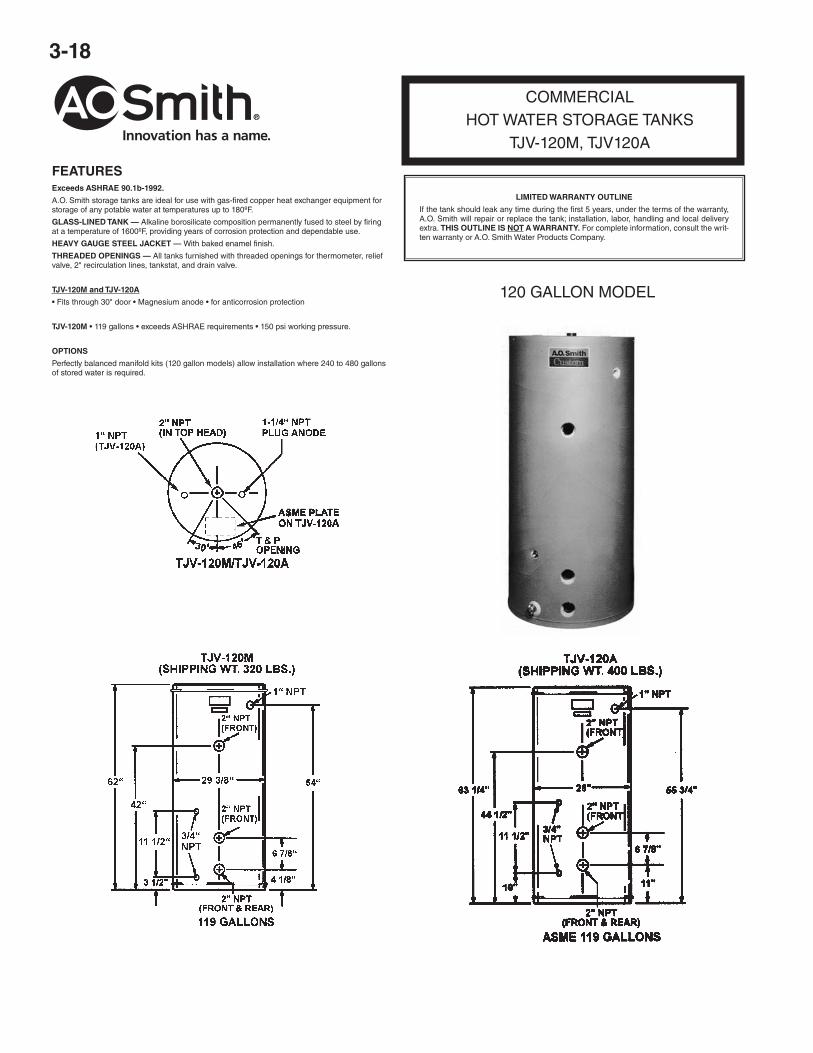
COMMERCIALHOT WATER STORAGE TANKS
TJV-120M, TJV120A
FEATURESExceeds ASHRAE 90.1b-1992.
A.O. Smith storage tanks are ideal for use with gas-fired copper heat exchanger equipment forstorage of any potable water at temperatures up to 180ºF.
GLASS-LINED TANK — Alkaline borosilicate composition permanently fused to steel by firingat a temperature of 1600ºF, providing years of corrosion protection and dependable use.
HEAVY GAUGE STEEL JACKET — With baked enamel finish.
THREADED OPENINGS — All tanks furnished with threaded openings for thermometer, reliefvalve, 2" recirculation lines, tankstat, and drain valve.
TJV-120M and TJV-120A
• Fits through 30" door • Magnesium anode • for anticorrosion protection
Perfectly balanced manifold kits (120 gallon models) allow installation where 240 to 480 gallonsof stored water is required.
120 GALLON MODEL
LIMITED WARRANTY OUTLINE
If the tank should leak any time during the first 5 years, under the terms of the warranty,A.O. Smith will repair or replace the tank; installation, labor, handling and local deliveryextra. THIS OUTLINE IS NOT A WARRANTY. For complete information, consult the writ-ten warranty or A.O. Smith Water Products Company.
3-19
LARGE VOLUMEHOT WATER STORAGE TANKS
FEATURESA.O. Smith storage tanks are ideal for use with gas4i red copper heat exchangerequipment and other A. 0. Smith hot water systems for storage of any potable waterat temperatures as high as 180 degrees or lower.
GLASS-LINED — All internal surfaces exposed to water are glass-lined per ASMEHLW procedures, using an NSF approved glass-lining compound.
SIZES FROM 80 TO 1,000 GALLONS — All tanks in table on reverse side are nor-mally carried in stock. ASME construction available on all except 80 and 120 gallonsize.
HORIZONTAL OR VERTICAL MOUNTING — Except TL-500 which is horizontal.
MAGNESIUM ANODES — For extra protection.
Stock tanks T-140A and larger have threaded leg sockets on one head for vertical in-stallations. (Except TL-500).
WORKING PRESSURES
Tanks tested at test pressures assigned in accordance with working pressures shownin table on reverse side.
OPTIONS
• ASME and National Board Certification sheets
• Tank saddles - two per horizontal tank required.
NOTE: Custom line tanks available to meet military specifications, various workingpressures, lifting lugs, handholes, manholes, special opening sizes or loca-tions. Refer to sheet A 411.0.
LIMITED WARRANTY OUTLINE
If the tank should leak any time during the first 5 years, under the terms of the warranty,A.O. Smith will repair or replace the tank; installation, labor, handling and local deliveryare extra. THIS OUTLINE IS NOT A WARRANTY. For complete information, consult thewritten warranty or A.O. Smith Water Products Company.
Warranty does not apply to product installed outside of the United States of America or itsterritorial possessions and Canada.
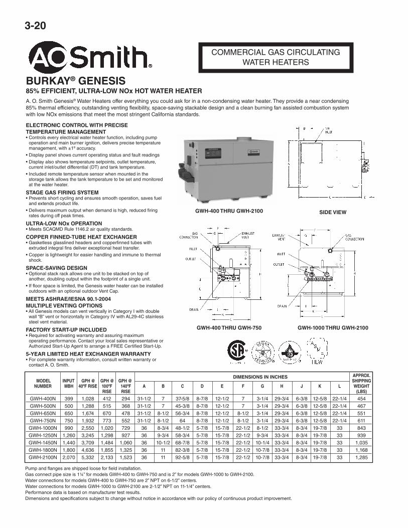
Pump and flanges are shipped loose for field installation.Gas connect pipe size is 1¼” for models GWH-400 to GWH-750 and is 2” for models GWH-1000 to GWH-2100.Water connections for models GWH-400 to GWH-750 are 2” NPT on 6-1/2” centers.Water connections for models GWH-1000 to GWH-2100 are 2-1/2” NPT on 11-1/4” centers.Performance data is based on manufacturer test results.Dimensions and specifications subject to change without notice in accordance with our policy of continuous product improvement.
DIMENSIONS IN INCHES
ELECTRONIC CONTROL WITH PRECISETEMPERATURE MANAGEMENT• Controls every electrical water heater function, including pump
operation and main burner ignition, delivers precise temperaturemanagement, with ±1º accuracy.
• Display panel shows current operating status and fault readings
• Display also shows temperature setpoints, outlet temperature,current inlet/outlet differential (DT) and tank temperature.
• Included remote temperature sensor when mounted in thestorage tank allows the tank temperature to be set and monitoredat the water heater.
STAGE GAS FIRING SYSTEM• Prevents short cycling and ensures smooth operation, saves fuel
and extends product life.
• Delivers maximum output when demand is high, reduced firingrates during off peak times.
ULTRA-LOW NOx OPERATION• Meets SCAQMD Rule 1146.2 air quality standards.
COPPER FINNED-TUBE HEAT EXCHANGER• Gasketless glasslined headers and copperfinned tubes with
extruded integral fins deliver exceptional heat transfer.
• Copper is lightweight for easier handling and immune to thermalshock.
SPACE-SAVING DESIGN• Optional stack rack allows one unit to be stacked on top of
another, doubling output within the footprint of a single unit.
• If floor space is limited, the Genesis water heater can be installedoutdoors with an optional outdoor Vent Cap.
MEETS ASHRAE/IESNA 90.1-2004MULTIPLE VENTING OPTIONS• All Genesis models can vent vertically in Category I with double
wall “B” vent or horizontally in Category IV with AL29-4C stainlesssteel vent material.
FACTORY START-UP INCLUDED• Required for activating warranty and assuring maximum
operating performance. Contact your local sales representative orAuthorized Start-Up Agent to arrange a FREE Certified Start-Up.
5-YEAR LIMITED HEAT EXCHANGER WARRANTY• For complete warranty information, consult written warranty or
contact A. O. Smith.
BURKAY® GENESIS85% EFFICIENT, ULTRA-LOW NOx HOT WATER HEATERA. O. Smith Genesis® Water Heaters offer everything you could ask for in a non-condensing water heater. They provide a near condensing85% thermal efficiency, outstanding venting flexibility, space-saving stackable design and a clean burning fan assisted combustion systemwith low NOx emissions that meet the most stringent California standards.
GWH-400 THRU GWH-2100 SIDE VIEW
GWH-400 THRU GWH-750 GWH-1000 THRU GWH-2100
3-21
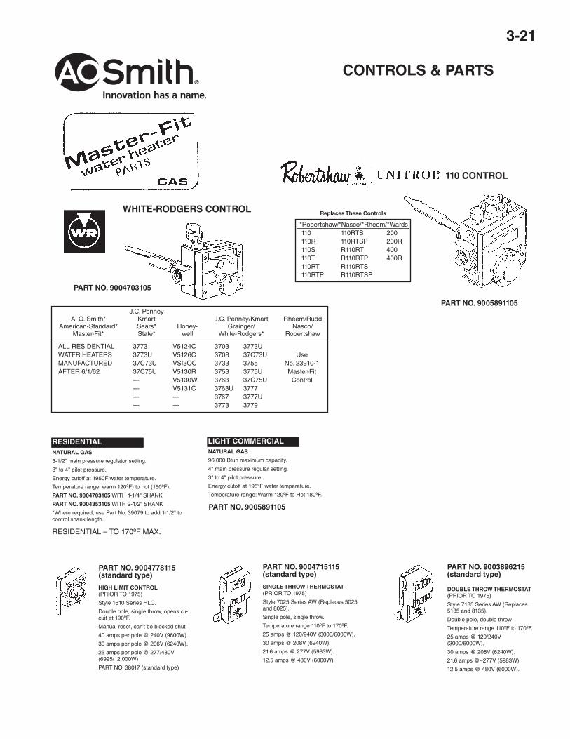
DOUBLE THROW THERMOSTAT(PRIOR TO 1975)
Style 7135 Series AW (Replaces5135 and 8135).
Double pole, double throw
Temperature range 110ºF to 170ºF.
25 amps @ 120/240V(3000/6000W).
30 amps @ 208V (6240W).
21.6 amps @~277V (5983W).
12.5 amps @ 480V (6000W).
WHITE-RODGERS CONTROL
110 CONTROL
PART NO. 9004703105
PART NO. 9005891105
RESIDENTIAL – TO 170ºF MAX.
PART NO. 9005891105
J.C. Penney A. O. Smith* Kmart J.C. Penney/Kmart Rheem/Rudd American-Standard* Sears* Honey- Grainger/ Nasco/ Master-Fit* State* well White-Rodgers* Robertshaw
MAIN BURNER* 9005889205(2)* 9005889205(2)* 9005889205(3)* 9005889205(4)* 9005889205(6)* 9005889205(8)*
1) PILOT BURNER: #880 SERIES 9004988115 9004988115 9004988115 9004988115 9004988115 9004988115 #882 SERIES 9004998215 9004998215 9004998215 9004998215 9004998215 9004998215 2) SPARK MODULE #880 SERIES 9004470205 9004470205 9004470205 9004470205 9004470205 9004470205 #882 SERIES AS 78191-2 AS 78191-2 AS 78191-2 AS 78191-2 AS 78191-2 AS 78191-2
4) GAS VALVE AS 77937-2 AS 77937-2 AS 77937-2 AS 77937-2 AS 77937-2 AS 77937-4
5, 6) DRAFT HOOD: HORIZONTAL BTC 197 ONLY BTC 240A ONLY CALL CALL CALL CALL CALL CALL VERT. LO-PROFILE VERTICAL
Hi Capacity Commercial T&P ValvesThe Apollo 18C-500 Series bronze automatic temperature and pressure relief valves areused for protection of high capacity commercial hot water heaters and storage tanks.
ELEMENT AGA/CGA TEMP. ASME PRESS. MODEL # INLET OUTLET LENGHT STEAM RATING STEAM RATING 18C-511-5-125 3/4" M 3/4" F 4.38" 205,000 1,619,000 18C-511-5-150 3/4" M 3/4" F 4.38" 205,000 1,912,000 18C-521-5-125 1”M 1”F 4.75” 500,000 1,825,000 18C-521-5-150 1”M 1”F 4.75” 500,000 2,155,000 18C-522-5-125 1”M 1”F 4.75” 750,000 3,070,000 18C-522-5-150 1”M 1”F 4.75” 750,000 3,625,000
A.S.M.E. WATER PRESSURE RELIEF VALVEBronze body relief valves for pressure protection only of all types of hot waterheating boiler equipment.
NO.100 XLA thermostat with a thermo-bonded non-metallic protective coating and a pro-tective dialectric barrier to protect thermostat from accumulations of mineraldeposits.
THERM-X-TROL®THERMAL EXPANSION ABSORBER. FORPOTABLE WATER HEATERS ONLY.
* STANDARD AIR CHARGE 40 PSI.
AGA/CGA TEMP. MODEL INLET OUTLET HEIGHT STEAM RATING