+ All Categories
Home > Documents > Manufacturer’s Reprint Power Plant SNCR/SCR Units ... Library/gas-detection... · Power Plant...

Manufacturer’s Reprint Power Plant SNCR/SCR Units ... Library/gas-detection... · Power Plant...

Date post: 26-Jul-2018
Category:
Upload: ngoanh
View: 222 times
Download: 0 times
Share this document with a friend
2
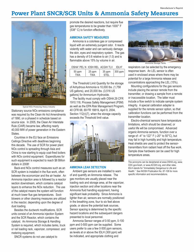
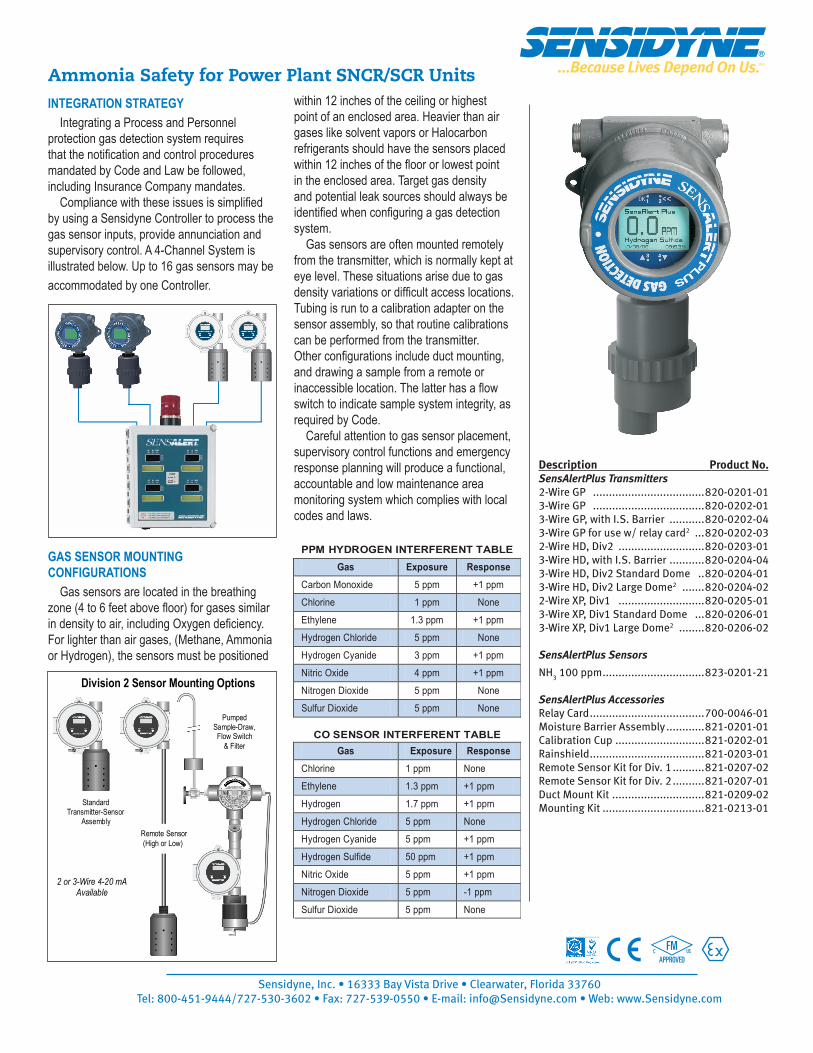
Power Plant SNCR/SCR Units & Ammonia Safety Measures Manufacturer’s Reprint Stationary source NOx emissions compliance was required by the Clean Air Act Amendments of 1990, on a phased in schedule based on source size. In 2005, the Clean Air Interstate Rule (CAIR) became law, affecting nearly 40,000 MW of power generation in the Eastern States. Countries in the EU face an Emissions Ceilings Directive with deadlines beginning this decade. The use of SCR for power plant NOx control is spreading through Asia and China is now starting to equip coal-fired boilers with NOx control equipment. Expenditures for such equipment is expected to reach $8 Billion dollars in 2008! Back-end NOx control measures such as an SCR system is installed in the flue work, often between the economizer and the air heater. An Ammonia injection area is followed by a reactor section downstream, which contains catalyst layers to enhance the NOx reduction. The use of the catalyst means the system will function at much lower flue gas temperatures. Soot- blowers or other cleaning measures are utilized in the reactor, depending upon the degree of dust loading. Besides the ductwork modifications, SCR units consist of an Ammonia injection System and the SCR Reactor, which contains the catalyst. An Ammonia Storage & Handling System is required, which includes tanks, truck or rail loading rack, vaporizer, compressor, and metering equipment. SNCR systems do not use catalyst to promote the desired reactions, but require flue gas temperatures to be greater than 1000° F (538° C) to function effectively. AMMONIA SAFETY MEASURES Ammonia is a colorless gas or compressed liquid with an extremely pungent odor. It reacts violently with water and can seriously damage the skin, eyes and respiratory system. The gas has a density of 0.6 relative to air (1.0) and is flammable above 15% by volume in air. OSHA 1 PEL N IOSH REL ACGIH TLV IDLH 2 50 ppm TWA 25 ppm TWA 35 ppm STEL 300 ppm The Threshold Limit Quantity for the storage of Anhydrous Ammonia is 10,000 lbs. (1,758 US gallons), and 20,000 lbs. (3,516 US gallons) for Ammonium Hydroxide. The facility must comply with OSHA 29 CFR 1910.118, Process Safety Management (PSM) as well as the EPA Risk Management Program, 40 CFR 68, 69 FR 18819, April 9, 2004, Section 112(r)(7), when the storage capacity exceeds the Threshold limit value. AMMONIA LEAK DETECTION Ambient gas sensors are installed to warn of and quantify an Ammonia release. The gas monitors are usually placed near the loading rack and storage area, at the vaporizer, injection section and other locations near the Ammonia fluid handling equipment, having significant leak probability. Since Ammonia is lighter than air, sensors are normally positioned in the breathing zone, four to six feet above grade, or above the potential leak sources. Sensor spacing is determined by the specific hazard locations and the subsequent dangers presented to local personnel. Ammonia Sensor ranges of 0-50 ppm, 0-100 ppm and 0-500 ppm can be supplied. Some users prefer to use a few 0-500 ppm sensors, as levels at or above the IDLH (300 ppm) will be indicated, and appropriate clothing and respirators can be selected by the emergency response team. An LEL sensor is often used in enclosed areas where there may be potential for a large Ammonia release and concentrations approaching the LEL (15%). Mounting configurations for the gas sensors include placing the sensor remote from the transmitter, or drawing a sample from a remote or inaccessible location. The latter must include a flow switch to indicate sample system integrity. A special calibration adapter is supplied for the remote sensor option, so that calibration functions can be performed from the transmitter location. Electro-chemical sensors have temperature limitations, which should be observed, or useful life will be compromised. Advanced organic Ammonia sensors, function over a range of –4° to 122° F (–20° to 50°C), but may fail in high humidity and high temperature. Heat shields are used to protect the sensor- transmitters from radiant heat off the flue work. Sample draw hardware can be used for high temperature areas. _____________________________________ The acronyms can be deciphered at www.OSHA.org, www. CDC.gov/niosh, or www.ACGIH.org, and other sites. IDLH stands for “Immediately Dangerous to Life and Health.” See NIOSH Publication No. 87-108 for more specific information and recommendations. Typical NOx Producing Heavy Industry Ammonia Storage Tanks
Transcript

Power Plant SNCR/SCR Units & Ammonia Safety MeasuresManufacturer’s Reprint

Stationary source NOx emissions compliance was required by the Clean Air Act Amendments of 1990, on a phased in schedule based on source size. In 2005, the Clean Air Interstate Rule (CAIR) became law, affecting nearly 40,000 MW of power generation in the Eastern States. Countries in the EU face an Emissions Ceilings Directive with deadlines beginning this decade. The use of SCR for power plant NOx control is spreading through Asia and China is now starting to equip coal-fired boilers with NOx control equipment. Expenditures for such equipment is expected to reach $8 Billion dollars in 2008! Back-end NOx control measures such as an SCR system is installed in the flue work, often between the economizer and the air heater. An Ammonia injection area is followed by a reactor section downstream, which contains catalyst layers to enhance the NOx reduction. The use of the catalyst means the system will function at much lower flue gas temperatures. Soot-blowers or other cleaning measures are utilized in the reactor, depending upon the degree of dust loading. Besides the ductwork modifications, SCR units consist of an Ammonia injection System and the SCR Reactor, which contains the catalyst. An Ammonia Storage & Handling System is required, which includes tanks, truck or rail loading rack, vaporizer, compressor, and metering equipment. SNCR systems do not use catalyst to

promote the desired reactions, but require flue gas temperatures to be greater than 1000° F (538° C) to function effectively.

AMMONIA SAFETY MEASURES Ammonia is a colorless gas or compressed liquid with an extremely pungent odor. It reacts violently with water and can seriously damage the skin, eyes and respiratory system. The gas has a density of 0.6 relative to air (1.0) and is flammable above 15% by volume in air.

OSHA1 PEL N IOSH REL ACGIH TLV IDLH2

50 ppm TWA

25 ppm TWA

35 ppmSTEL

300 ppm

The Threshold Limit Quantity for the storage of Anhydrous Ammonia is 10,000 lbs. (1,758 US gallons), and 20,000 lbs. (3,516 US gallons) for Ammonium Hydroxide. The facility must comply with OSHA 29 CFR 1910.118, Process Safety Management (PSM) as well as the EPA Risk Management Program, 40 CFR 68, 69 FR 18819, April 9, 2004, Section 112(r)(7), when the storage capacity exceeds the Threshold limit value.

AMMONIA LEAK DETECTION Ambient gas sensors are installed to warn of and quantify an Ammonia release. The gas monitors are usually placed near the loading rack and storage area, at the vaporizer, injection section and other locations near the Ammonia fluid handling equipment, having significant leak probability. Since Ammonia is lighter than air, sensors are normally positioned in the breathing zone, four to six feet above grade, or above the potential leak sources. Sensor spacing is determined by the specific hazard locations and the subsequent dangers presented to local personnel. Ammonia Sensor ranges of 0-50 ppm, 0-100 ppm and 0-500 ppm can be supplied. Some users prefer to use a few 0-500 ppm sensors, as levels at or above the IDLH (300 ppm) will be indicated, and appropriate clothing and

respirators can be selected by the emergency response team. An LEL sensor is often used in enclosed areas where there may be potential for a large Ammonia release and concentrations approaching the LEL (15%). Mounting configurations for the gas sensors include placing the sensor remote from the transmitter, or drawing a sample from a remote or inaccessible location. The latter must include a flow switch to indicate sample system integrity. A special calibration adapter is supplied for the remote sensor option, so that calibration functions can be performed from the transmitter location. Electro-chemical sensors have temperature limitations, which should be observed, or useful life will be compromised. Advanced organic Ammonia sensors, function over a range of –4° to 122° F (–20° to 50°C), but may fail in high humidity and high temperature. Heat shields are used to protect the sensor-transmitters from radiant heat off the flue work. Sample draw hardware can be used for high temperature areas._____________________________________The acronyms can be deciphered at www.OSHA.org, www.CDC.gov/niosh, or www.ACGIH.org, and other sites.IDLH stands for “Immediately Dangerous to Life and Health.” See NIOSH Publication No. 87-108 for more specific information and recommendations.

Typical NOx Producing Heavy Industry

Ammonia Storage Tanks

Pumped Sample-Draw, Flow Switch

& Filter

Division 2 Sensor Mounting Options

Remote Sensor (High or Low)

Standard Transmitter-Sensor

Assembly

2 or 3-Wire 4-20 mA Available

Description Product No.SensAlertPlus Transmitters 2-Wire GP ...................................820-0201-013-Wire GP ...................................820-0202-01 3-Wire GP, with I.S. Barrier ...........820-0202-043-Wire GP for use w/ relay card2 ...820-0202-032-Wire HD, Div2 ...........................820-0203-01 3-Wire HD, with I.S. Barrier ...........820-0204-04 3-Wire HD, Div2 Standard Dome ..820-0204-013-Wire HD, Div2 Large Dome2 .......820-0204-022-Wire XP, Div1 ...........................820-0205-013-Wire XP, Div1 Standard Dome ...820-0206-013-Wire XP, Div1 Large Dome2 ........820-0206-02

SensAlertPlus Sensors

NH3 100 ppm ................................823-0201-21

SensAlertPlus AccessoriesRelay Card ....................................700-0046-01Moisture Barrier Assembly ............821-0201-01Calibration Cup ............................821-0202-01Rainshield ....................................821-0203-01Remote Sensor Kit for Div. 1 ..........821-0207-02Remote Sensor Kit for Div. 2 ..........821-0207-01Duct Mount Kit .............................821-0209-02Mounting Kit ................................821-0213-01

PPM HYDROGEN INTERFERENT TABLE Gas Exposure Response

Carbon Monoxide 5 ppm +1 ppm Chlorine 1 ppm None Ethylene 1.3 ppm +1 ppm Hydrogen Chloride 5 ppm None Hydrogen Cyanide 3 ppm +1 ppm Nitric Oxide 4 ppm +1 ppm Nitrogen Dioxide 5 ppm None Sulfur Dioxide 5 ppm None

CO SENSOR INTERFERENT TABLEGas Exposure Response

Chlorine 1 ppm None Ethylene 1.3 ppm +1 ppm Hydrogen 1.7 ppm +1 ppm Hydrogen Chloride 5 ppm None Hydrogen Cyanide 5 ppm +1 ppm Hydrogen Sulfide 50 ppm +1 ppm Nitric Oxide 5 ppm +1 ppm Nitrogen Dioxide 5 ppm -1 ppm Sulfur Dioxide 5 ppm None

AMMONIA INTERFERENT TABLE Gas Exposure Response

Alcohols 1000 ppm None Carbon Dioxide 5000 ppm None Carbon Monoxide 100 ppm None Hydrocarbons % Range None Hydrogen 10,000 ppm None Hydrogen Sulfide 10 ppm +1 ppm

Ammonia Safety for Power Plant SNCR/SCR UnitsINTEGRATION STRATEGY Integrating a Process and Personnel protection gas detection system requires that the notification and control procedures mandated by Code and Law be followed, including Insurance Company mandates. Compliance with these issues is simplified by using a Sensidyne Controller to process the gas sensor inputs, provide annunciation and supervisory control. A 4-Channel System is illustrated below. Up to 16 gas sensors may be accommodated by one Controller.

GAS SENSOR MOUNTING CONFIGURATIONS Gas sensors are located in the breathing zone (4 to 6 feet above floor) for gases similar in density to air, including Oxygen deficiency. For lighter than air gases, (Methane, Ammonia or Hydrogen), the sensors must be positioned

within 12 inches of the ceiling or highest point of an enclosed area. Heavier than air gases like solvent vapors or Halocarbon refrigerants should have the sensors placed within 12 inches of the floor or lowest point in the enclosed area. Target gas density and potential leak sources should always be identified when configuring a gas detection system. Gas sensors are often mounted remotely from the transmitter, which is normally kept at eye level. These situations arise due to gas density variations or difficult access locations. Tubing is run to a calibration adapter on the sensor assembly, so that routine calibrations can be performed from the transmitter. Other configurations include duct mounting, and drawing a sample from a remote or inaccessible location. The latter has a flow switch to indicate sample system integrity, as required by Code. Careful attention to gas sensor placement, supervisory control functions and emergency response planning will produce a functional, accountable and low maintenance area monitoring system which complies with local codes and laws.


Recommended