MANUFACTURING COST ANALYSIS OF 1 KW AND 5 KW SOLID OXIDE FUEL CELL (SOFC) FOR AUXILLIARY P OWER APPLICATIONS Prepared by: BATTELLE Battelle Memorial Institute 505 King Avenue Columbus, OH 43201 Prepared for: U.S. Department of Energy Golden Field Office Golden, CO DOE Contract No. DE-EE0005250 February 7, 2014
Transcript
MANUFACTURING COST ANALYSIS OF 1 KW AND 5 KW SOLID OXIDE FUEL CELL
(SOFC) FOR AUXILLIARY POWER
APPLICATIONS Prepared by:
BATTELLE Battelle Memorial Institute 505 King Avenue Columbus, OH 43201 Prepared for: U.S. Department of Energy Golden Field Office Golden, CO DOE Contract No. DE-EE0005250 February 7, 2014
This report is a work prepared for the United States Government by Battelle. In no event shall either the United States Government or Battelle have any responsibility or liability for any consequences of any use, misuse, inability to use, or reliance upon the information contained
herein, nor does either warrant or otherwise represent in any way the accuracy, adequacy, efficacy, or applicability of the contents hereof.
iii
Executive Summary
Background
Under a cooperative agreement with the Department of Energy’s (DOE’s) Fuel Cell Program, Battelle has been tasked to provide an independent assessment of fuel cell manufacturing costs at
varied volumes and alternative system designs.
This report provides cost estimates for the manufacture of 1 kW and 5 kW solid oxide fuel cells (SOFC) designed for auxiliary power unit applications using high-volume manufacturing processes at annual production volumes of 100, 1000, 10,000, and 50,000 units.
Aproach
Battelle’s cost analysis methodology is a four-step approach:
Step 1 – Market Assessment. In this step, we identified the operational and performance requirements
(e.g., hours of operation, frequency, lifetime expected) of the target application and market. This
information formed the basis for selecting the right system design and fuel cell type for user requirements
and the appropriate production volumes to consider in the modeling exercise.
Step 2 – System Design. A fuel cell auxialliary power unit design was developed as a system
representative of typical design based on literature, manufacturer feedback and engineering expertise of
Battelle.
Step 3 – Cost Modeling. Battelle gathered vendor quotes for material costs, production equipment, and
outsourced components. Custom manufacturing process models were defined where necessary and
parametrically modeled based on knowledge of the machine, energy and labor requirements for individual
steps that comprise the custom process.
Step 4 – Sensitivity Analysis/Lifecycle Cost Analysis. A sensitivity analysis was performed to determine which design parameters or assumptions have the most effect upon the stack and system cost. Lifecycle costs of the fuel cell APU were compared to equivalent technologies in the market today.
Results
Overall the final cost was analyzed in four distinct categories: the capital cost of manufacturing
equipment, the direct cost of material and assembly of the stack, the expense of balance of plant
hardware, and the final cost of complete system assembly and testing it.
The primary driver of overall APU system cost is the Balance of Plant hardware, accounting for 63-88%
of total system costs across the production volumes analyzed. The complex nature of onboard fuel
reforming and the high temperature requirments for Solid Oxide Fuel Cell operation keep the part count
and material costs high.
The stack costs is most sensitive to change in metal components, as the quantity of high temperature steel
makes up the bulk of the stack cost. BOP costs are most sensistive to heat transfer and power conversion
equipment; specifically, the amount of heat transfer required to heat fuel feed streams, cool reformate for
desulfurization and reheat upstream of the stack is significant.
iv
Table of Contents
Executive Summary ........................................................................................................................ iii
Table of Contents ............................................................................................................................ iv
List of Figures .................................................................................................................................. v
List of Tables .................................................................................................................................. vi
4 System Design ........................................................................................................................13
4.1 General System Description ...................................................................................... 13 4.2 Electrical System ....................................................................................................... 18 4.3 Balance of Plant (BOP) ............................................................................................. 20
5 Manufacturing Cost Analysis .................................................................................................22 5.1 Stack Manufacturing Process and Cost Assumptions ............................................... 23
5.2 Special BOP Manufacturing Cost Assumptions ........................................................ 32 5.3 Electrical System Cost Assumptions ......................................................................... 34 5.4 Balance of Plant Cost Assumptions........................................................................... 36
5.5 System Assembly and Learning Curve Assumptions................................................ 41 5.6 Capital Cost Assumptions.......................................................................................... 41
6 Limitations of the Analysis.....................................................................................................42 6.1 Manufacturing Costs.................................................................................................. 42 6.2 Balance of Plant Hardware Costs .............................................................................. 43
9 Lifecycle Cost Analysis of Fuel Cells ....................................................................................50
10 Conclusions.............................................................................................................................51 10.1 System Cost Summary............................................................................................... 51 10.2 Results........................................................................................................................ 56
Appendix A – Stack Manufacturing Process and Cost Assumptions ......................................... A-2 A.1 Ceramic Slurry Production Process ......................................................................... A-2
A.2 Ceramic Tape Casting Process ................................................................................ A-7 A.3 Anode Blanking Process ........................................................................................ A-12 A.4 Ceramic Screen Printing Process ........................................................................... A-15
A.5 Kiln Firing Process ................................................................................................ A-22 A.6 Final Trim Process ................................................................................................. A-25
v
A.7 Interconnect Manufacturing Process ..................................................................... A-27 A.8 Picture Frame Production Process ......................................................................... A-37
Engine ................................................................................................................................. 50 Table 10-1. 1 kW APU SOFC System per Unit Cost Summary ........................................................... 51 Table 10-2. 5 kW APU SOFC System Per Unit Cost Summary........................................................... 54
Page 1
1 Introduction
Battelle is conducting manufacturing cost assessments of fuel cells for stationary and non-automotive
applications to identify the primary cost drivers impacting successful product commercialization. Battelle,
under a 5-year cooperative agreement with the Department of Energy’s (DOE’s) Fuel Cell Program, will
provide an independent assessment of fuel cell manufacturing costs at varied volumes and alternative
system designs. This report provides cost estimates for the manufacture of 1 kW and 5 kW solid oxide
fuel cells (SOFC) designed for auxiliary power unit applications. This report identifies the manufacturing
costs of fuel cells using high-volume manufacturing processes at annual production volumes of 100,
1000, 10,000, and 50,000 units. The system design and manufacturing volumes were defined using
Battelle’s fuel cell system integration expertise and refined through a discussion with industry partners.
The report presents our approach; the design of the system, design assumptions, and manufacturing
processes modeled using the design for manufacturing assembly (DFMATM
) software; costs of the
system, sub-system, and specific components; the main cost drivers identified through a sensitivity
analysis; and a summary of opportunities for cost reduction.
2 Approach
Battelle’s cost analysis methodology is a four-step approach (Figure 2-1):
This approach has been successfully applied to previous cost analyses developed by Battelle.1,2
1 Battelle. 2011. The High Volume Manufacture Cost Analysis of 5 kW Direct Hydrogen Polymer Electrolyte
Membrane (PEM) Fuel Cell for Backup Power Applications. Contract No. DE-FC36GO13110. 2 H. Stone, K. Mahadevan, K. Judd, H. Stein, V. Contini, J. Myers, J. Sanford , J. Amaya, and D. Paul. 2006.
The first step in our methodology, Step 1 Market Assessment, is to ensure that we select the right fuel cell
type and appropriate production volumes to meet market requirements. In this step, we identified the
operational and performance requirements (e.g., hours of operation, frequency, lifetime expected) of the
target application and market. Using this information, an assessment of the user requirements for a fuel
cell product was defined. We also completed a quick survey of the market through an industry dialogue
to estimate the number of units in the market and the expected market growth for fuel cells in auxiliary
power unit applications. This information formed the basis for selecting the right system design and fuel
cell type for user requirements and the appropriate production volumes to consider in the modeling
exercise.
Step 2 System Design, , a literature review of fuel cell designs for auxiliary power unit applications,
component design and manufacturing processes, possible improvements in system design and
manufacturing was completed. From these results the basic construction and operational parameters for a
fuel cell stack and system were defined as well as potential improvements. The fuel cell design
developed does not focus on an individual manufacturer’s designs, but a system representative of typical
design based on literature and engineering expertise of Battelle. The stack and the system design were
vetted with industry stakeholders to ensure feasibility of the design, to identify possible improvements,
and to determine current and alternate manufacturing approaches. A finalized design and projected
improvements form the basis for developing the bill of materials (BOM). Decisions were then made
about which components would be manufactured internally and which would be outsourced. For
internally manufactured components (including applicable balance of plant (BOP) components),
manufacturing processes and production equipment are defined in detail.
In Step 3 Cost Modeling, Battelle gathered vendor quotes for material costs, production equipment, and
outsourced components. Custom manufacturing process models were defined where necessary and
Market Assessment System Design Cost Modeling Sensitivity
Analysis/Lifecycle Cost Analysis
• Conduct literature
search
• Develop system design
• Gather industry input
• Size components
• Gather stakeholder
input
• Refine design
• Develop Bill of
Materials
• Define manufacturing
processes
• Estimate equipment
requirements
• Gather vendor quotes
• Define material costs
• Estimate capital
expenditures
• Determine outsourced
component costs
• Estimate system
assembly
• Develop preliminary
costs
• Gather stakeholder
input
• Refine models and
update costs
• Sensitivity analysis
of individual cost
contributors
• Characterization of
potential markets
• Identification of
operational and
performance
requirements
• Evaluation of fuel
cell technologies
relative to
requirements
• Selection of specific
systems for cost
modeling
Page 3
parametrically modeled based on knowledge of the machine, energy, and labor requirements for
individual steps that comprise the custom process. The sequence of actions required to assemble the
components and test the final fuel cell system were developed and analyzed for cost reduction
opportunities through component consolidation and process optimization. Manufacturing quality control
required was based on suggestions of equipment vendors and Battelle’s experience with product
manufacturing. Outsourced components costs were estimated through vendor quotes. Mathematic
functions for scaling factors were developed to estimate the changes to outsourced components and
material costs with production volumes when vendor quotes for higher volumes are not available. These
were derived using engineering rules of thumb and estimates from other manufacturing processes and
considered impacts on system design. Using the Design for Manufacturing Assembly (DFMATM
)
software, component costs calculated from both custom and library manufacturing processes and the
outsourced components were incorporated into the assembly and test sequence models to determine the
final cost of producing the fuel cell systems. The output of the DFMATM
models were also used to
calculate production line utilization to determine the number of individual process lines required to
support various product demand levels, as input to the manufacturing capital cost model. Capital
equipment expenditures for production were amortized over a 20-year period and the annual amortized
cost will be distributed over production volume for that year. Financial assumptions that were used are
consistent with the DOE Hydrogen Analysis (H2A) model. Total stack system costs including capital
expenditures were then estimated for the baseline system and projected improvements.
In Step 4 Sensitivity Analysis, a sensitivity analysis was performed to determine which design parameters
or assumptions have the most effect upon the stack and system cost. Single factor sensitivity analysis was
performed. Single factor sensitivity analysis helps determine the impact of individual parameters on
system costs. Based on these results, insights into the design optimization of fuel cell systems are
provided to reduce the total system cost and total cost of ownership.
3 Market Assessment
In 2012 Battelle performed a market analysis to support the selection of the system and fuel cell type for
the cost analysis. 3
For this study, Battelle focused on fuel cell systems for auxiliary power applications on
transportation equipment (RV, truck, aircraft,watercraft). Battelle reviewed commercial auxiliary power
units to gain a general understanding of the characteristics and equipment types available in the market.
Battelle gathered information on the operational and performance requirements for a range of APU
applications. This assessment included consideration of the characteristics of deployed APU systems,
including fuel cell technologies. Characteristics of interest included:
• Application
• Types of equipment currently used
• Load capability/system size
• Hours of use
• Reliability/durability performance or requirements
3 Battelle, 2012. Task 2: Market and Application Requirements to Support Fuel Cell Design: Auxiliary Power Units
Report to the DOE. DOE Contract No. DE-EE0005250/001.
Page 4
Sources of information included:
• Previous analyses and research
• Fuel cell manufacturers
• APU equipment manufacturers and end-users
• Industry Associations
• Journal articles
• Internet searches
3.1 Transportation APU Market Summary
Four main markets for APUs are recreational vehicle (RV), commercial trucking, aviation, and maritime. Additional market applications with the potential to use APUs include trains, mobile medical care vehicles (ambulance and similar), and the entertainment industry. Currently available APUs are powered by internal combustion (IC) engine generators (spark ignition, diesel), gas turbines, and batteries. Table 3-1 summarizes the market characterization performed by Battelle including typical APU power sources, sizes, and specific market drivers. For all markets a value proposition can be made based on the well-known advantages of fuel cell technologies including higher efficiency, decreased emissions, and lower noise. Table 3-1 identifies additional market drivers that would further encourage market adoption of fuel cell APUs.
Page 5
Table 3-1. Market Summary for APU Applications
Market Application Current APU
Types Standalone APU Size Range
Specific Commercial Market Drivers for Fuel Cell
Technology
Recreational Vehicle (RV)
Battery
IC Engine Fuel Cell
1-12 kW (standalone) As low as 50 to 100 W (hybrid)
4
Campsite quiet-hour regulations
Commercial Truck Battery
IC Engine
Fuel Cell
1 to 7 kW (standalone APU) 1 to 5 kW (hybrid APU)
10 to 20 kW (mobile refrigeration)5
Evolving local and national noise and emission
regulations6,7
Aviation IC Engine (Gas
Turbine) 100 to 450 kW (traditional APU) 10 to 100 kW (peak reduction)
Notably low efficiency (15%)
of existing APUs8
Increased demand from
More-Electric-Aircraft (MEA) and future All Electric Aircraft
(AEA)
Maritime Battery
IC Engine 5 to 500 kW (small, including leisure)
9
100 kW to 5 MW (commercial )10
NA
Regulatory market drivers will facilitate the rapid adoption of commercial truck APUs, particularly those with advantageous noise and emissions characteristics. The truck APU market has also been the primary focus of fuel cell manufacturers. Detailed product specifications for several existing APUs for Commercial Truck applications are listed in Table 3-2. Peak power requirements were not available for individual units. However, manufacturers provided general peak power requirements of 4-6 kW for commercial trucks. Physical dimensions, weight, and maintenance requirements are important considerations as well. APU power modules must be designed to fit onboard a vehicle without significantly restricting available space or fuel economy.
4 “Frequently Asked Questions,” Energy For You, http://www.efoy.com/en/mobile-homes-faqs.html.
5 “Markets for Fuel Cell Auxiliary Power Units in Vehicles: A Preliminary Assessment, Louisiana Transportation
Research Center, http://www.ltrc.lsu.edu/TRB_82/TRB2003-001443.pdf 6 “Clean Air Nonroad Diesel – Tier 4 Final Rule, US Environmental Protection Agency,
http://www.epa.gov/nonroad-diesel/2004fr.htm. 7 American Transportation Research Institute Compendium of Idling Restrictions, January 2012.
8 Spenser, J., “Fuel Cells in the Air,” Boeing Frontiers, Vol. 03, Issue 3, July 2004, online edition,
Hoffman, D., “System Design: Lessons Learned, Generic Concepts, Characteristics & Impacts,” US Department of Energy, Energy Efficiency & Renewable Energy, Office of Naval Research,
Table 3-3. Summary Information for Fuel Cell APU Applications
Equipment Type
Fuel Cell Type System Size Market Status
Recreational
Vehicle
DMFC battery charger
<0.1 kW Over 17,500 EFOY units manufactured by SFC Energy sold between 2007 and 2010, primarily in Europe.
SOFC 125W Protonex product offering withdrawn to facil itate focus
on military applications.
PEM 1 kW Voller Energy product offering withdrawn by
manufacturer.
Commercial Truck
SOFC 3-5 kW Technology demonstrations and development by many, including Delphi, Cummins, and UC Davis. PEM 1-6 kW
Aviation SOFC and PEM 10 kW Limited to technology development & demonstration
programs – no deployed products .
Maritime SOFC PEM
HTPEM
5-30 kW 5-15 kW
13-50 kW
Limited to technology development & demonstration programs – no deployed products .
Additional specific APU demonstrations
Car PEM 5 kW Technology development/demonstration by UTC Power
Bus PEM 16 kW Technology development/demonstration by Hydrogenics
Garbage Truck PEM 32 kW Technology development/demonstration performed by
Heliocentris. There has been considerable interest, development, and demonstration of systems within the recreational vehicle, commercial truck, aviation, and maritime markets. A few limited demonstrations have been made for other applications including a luxury car, bus, and garbage truck. Additional information on the four primary markets and their associated demonstrations is listed below.
Recreational Vehicles In terms of total number of deployed systems, the RV sector leads the worldwide market in integrating fuel cells into onboard APUs. Over 17,500 fuel cell APUs for RVs have been sold in European markets. These APUs are hybrid systems that integrate a fuel cell stack of 100 W or less with vehicle batteries. While fuel cell technology has had success in the RV market for APUs in Europe, there are not strong economic or policy drivers for adoption of fuel cells in the U.S. market. Advantages of reduced noise and reduced pollution, compared to IC engine APUs, could lead to increased adoption of fuel cell APUs in the RV market provided costs are comparable.
Commercial Truck Over half the states in the U.S. maintain some form of anti-idling regulations, leading to an increase in demands for APUs for commercial trucks.
15 More stringent emissions regulations for
APUs also will drive the implementation of more efficient technologies for APUs. Typical power requirements for commercial truck APUs range from 1 to 7 kW.
There are approximately 700,000 trucks with sleeper berths currently deployed in the field, creating a significant potential market. A substantial portion of these, estimated at about 2/3 of the population, are long-haul sleeper trucks with an average trip length in excess of 500 miles. Long-haul trucks average approximately 1,456 hours of dicretionary idle operation per year,
15
American Transportation Research Institute Compendium of Idling Restrictions, January 2012.
mainly to maintain driver comfort levels16. The total population of freight trucks is nearly
5.2 million. Day-cab trucks idle for approximately 312 hours per year during loading/unloading queues or rest stops.
17 The higher efficiency of fuel cell technologies offers the potential to
reduce operating costs.
The combination of market drivers, market size, and technological readiness make the commercial truck market the most likely near-term application for commercial fuel cell APUs. Aviation Aviation is an emerging market for APU applications. In addition to using APUs for ground power, there is interest in using similar systems to reduce peak demands, particularly as future generations of airplanes are expected to have increased electric power demands. There is also interest in using a system similar to an APU as the primary power for Unmanned Aerial Vehicles (UAVs) or small planes. While the APU for ground use would typically range from 100 to 450 kW, an APU to trim in-flight peak demand could be as small as 20kW. UAV power systems can be as small as 3kW.
18
Maritime There is market interest in using fuel cell technologies for maritime applications due to the higher efficiency, lower emissions, and quieter operation of fuel cell systems. The potential fuel cell applications range from APUs for recreational and military vessels to primary power systems. The state of market development is very early with a broad selection of fuel cell technologies undergoing evaluation, development, and assessment. While there are a few commercial demonstration projects,
19 the current maritime market is largely driven by military objectives and
requirements.
To realize significant and immediate market penetration for commercial truck APUs it is assumed that the commercial truck APU will be fueled by ULSD. The technical targets for Fuel Cell APUs are taken from the DOE Multi-Year Research, Development, and Demonstration (MYRDD) plan and shown in Table 3-4.
20 Note that many of the requirements, including power density and specific
power, are competitive with existing products shown in Table 3-2.
16
Brodrick C, Brodrick Lipman TE, Farshchi M, Lutsey NP, Dwyer HA, Sperling D. et al. Evaluation of fuel cell auxil iary power units for heavy duty diesel trucks. Transportaion Research Part D 2002;7:303 –15. 17
DOE Hydrogen Program Record #9010, November 3, 2009. 18
DOD-DOE Aircraft Petroleum Use Reduction Workshop, http://www1.eere.energy.gov/hydrogenandfuelcells/ wkshp_aircraft_petrol_use.html . 19
DOE EERE 2010 Fuel Cell Technologies Market Report. 20
Fuel Cell Technologies Program Multi -Year Research, Development, and Demonstration Plan,
Table 3-4. DOE Technical Targets for APUs Operating on Ultra Low Sulfur Diesel
Characteristic 2011 Status 2013 Target 2015 Target 2020 Target
Electrical efficiency at rated power 25% 30% 35% 40%
Power density 17 W/L 30 W/L 35 W/L 40 W/L
Specific power 20 W/kg 35 W/kg 40 W/kg 45 W/kg
Factory Cost, stack + required balance of plant
(50,000 units annually, 5kW) $750/kW $700/kW $600/kW $500/kW
Factory cost, system
(50,000 units annually, 5kW) $2,000/kW $1,400/kW $1,200/kW $1,000/kW
Transient response (10 to 90% rated
power) 5 min 4 min 3 min 2 min
Startup time from: 20°C
Standby conditions
50 min 50 min
45 min 20 min
45 min 10 min
30 min 5 min
Degradation with cycling 2.6%/1,000 h 2%/1,000 h 1.3%/1,000 h 1%/1,000 h
Operating lifetime (time until >20% net power
degradation)
3,000 h 10,000 h 15,000 h 20,000 h
System availability (excluding scheduled maintenance)
97% 97.5% 98% 99%
Additional requirements specified in the MYRDD include:
The degradation requirement in Table 4 is expected to include daily cycles to standby condition and weekly cycles to full off condition (ambient temperature)
The system should meet durability criteria after exposure to vibration typical of transportation and highway operation
Ambient temperature range of -40 to 50°C
Ambient relative humidity range from 5% to 100%
Ambient dust levels up to 2 mg/m3
Assuming ULSD is the supply fuel, the higher tolerance to impurities of SOFC and HTPEM technologies gives them a considerable advantage over 80°C PEM technologies. The higher power to mass ratio associated with SOFC technologies offers an advantage relative to HTPEM. However, SOFC technologies will have a longer startup time. A HTPEM stack is capable of a more rapid startup, although this is somewhat tempered by the startup time of the associated reforming system.
3.2 APU Technology Selection
Battelle started with the entire range of systems sizes and technologies specified in the funding announcement DOE FOA-0000420. A matrix of possible systems was constructed using the system (size and fuel cell type) as columns and the specific APU application as rows. From this matrix, individual systems were removed from consideration in FY12 based upon typical market applications, state of technology development, or basic economic arguments. These reasons are identified with letters in
Table 3-5 and explained in detail below the table.
Some of the main outcomes of research being funded by DOE are technological advancement and reduced cost. Therefore, it will be worthwhile to reconsider the selection matrix in future years incorporating technological advances as well as lessons learned during prior years. Even though the
Page 10
commercial truck market is identified as the nearest market, consideration for other applications is
included in Table 3-5 to facilitate reconsideration in future years.
Table 3-5. APU Application Matrix
Technology P
EM
HT
PE
M
SOF
C
PE
M
HT
PE
M
SOF
C
PE
M
HT
PE
M
SOF
C
PE
M
HT
PE
M
SOF
C
PE
M
HT
PE
M
SOF
C
PE
M
HT
PE
M
SOF
C
System Size 1 kW 5 kW 10 kW 25 kW 100 kW 250 kW
AP
U A
pp
lica
tio
n
RV B B B B B B A A A A A A A A A A A A
Commercial Truck
C H 12 C H 12 D D D D D D D D D D D D
Maritime E E E E E E E E E E E E E E E E E E
Commercial Aviation
F F F F F F G G G G G G G G G G G G
Considered in FY12-FY13
Technology Selection Criteria and Notes
A. Based upon Battelle’s market research conducted in support of this project, fuel cell system sizes above 5 kW are not required to meet typical loads in RVs.
B. The advantages of fuel cell technology, particularly reduced noise, would be beneficial to the RV user. There is not a strong regulatory or financial market driver for fuel cell APUs for this application. We suggest that consideration of 1 and 5 kW systems for RV APUs be deferred until APU costs for similar sizes in other APU markets are developed. This will enable a general assessment of the cost competitiveness of fuel cell APUs for the RV market and determine if additional refinement of the APU cost model is beneficial.
C. A lack of hydrogen infrastructure means that the near-term applications for commercial truck APUs will most likely use reformate from ULSD for fuel. The additional cost, weight, and volume of equipment required to purify hydrogen to the requirements for a standard temperature PEM stack make this technology less attractive.
The selection should be revisited once comparative costs for a Material Handling Equipment 1 kW and 5 kW fuel cell systems based on PEM technology are developed.
21 If the PEM approach
offers significant advantages with respect to cost or size, it may be worth considering an APU based on PEM technology that includes the ULSD reforming and purification equipment.
D. OEM load profiles indicate typical loads expected for Class 8 sleeper trucks are from 2.5 kW to 4.0 kW.
22 An APU of 1 kW nominal size may be paired with batteries to meet peak demands.
23
Fuel cell systems of 10 kW and more are oversized for present and forecasted loads.
E. APUs for maritime applications were a focus of a DOE workshop in May 2011.24
The current state of technology development is proof-of-concept demonstrations. The demonstration systems
21
These analyses are planned for FY13 of the current project. 22
Hennessy, D., Solid Oxide Fuel Cell Development for Auxiliary Power in Heavy Duty Vehicle Applications, 2010
DOE Annual Merit Review. 23
Norrick, D., Diesel Fueled SOFC System for Class 7/Class 8 On-Highway Truck Auxiliary Power, 2010 DOE Annual Merit Review. 24
discussed in the DOE workshop generally had power levels of 400 kW and above. Applications ranging from 10kW and higher are potentially applicable to leisure and smaller vessels.
25
The state of development of market requirements and drivers for maritime APUs under 200 kW is very early. These applications should be revisited in future years of the project when the market requirements and drivers are more clearly defined and understood.
F. Aviation applications for fuel cell powered APUs were a focus of a DOE workshop in September 2010.
26 As with maritime applications, the market is very early. While the benefits of fuel cell
technology (reduced emissions, better fuel economy) are clear, the optimum implementation within both present and future aircraft isn’t clear. Systems as small as 10 kW have been evaluated for overall performance and ability to reduce peak loads.
27 Existing aviation APUs for
commercial aircraft range from 50 to 450 kW.28
Systems as large as 550 kW may be required, although near-term implementations sized around 100 kW are more likely.
29
G. Fuel cell technology development has focused on performance, durability, and reliability improvements beneficial to several market applications. The aviation market will require these to continue to advance, as well as focused development to improve performance relative to requirements specific to aviation applications including operation at altitude, tolerance for higher levels of shock and vibration, and improvements to specific power (power per unit weight). A significant gap exists between the current state of technology development and the market requirement for specific power.
While there is significant interest in the aviation APU market, considerations of this market are best delayed until future years of the project. In addition to meeting all the requirements of a ground application APU, an APU for aviation applications must meet several additional performance requirements. The most stringent of these is the specific power of the system. Current technology is approximately 35 W/kg. While this is approximately in line with DOE targets for the commercial truck APU market,
30 a tenfold increase to the range of 400 W/kg to
500 W/kg is believed to be necessary for the application to be viable in the aviation market.31
H. Discussions with industry indicates that SOFC is favored over HTPEM for this application leading to a lack of available information for HTPEM systems.
APU Size and Technology Selected for Analysis
Based on the application requirements of Table 3-3 and the technology selection matrix in Table 3-5 Battelle conducted a cost analysis in FY12 and FY13 of a fuel cell system for APU applications with 1 kW and 5 kW net fuel cell system powers. Annual production volumes of 100, 1,000, 10,000, and 50,000
25
Hoffman, D., System Design: Lessons Learned, Generic Concepts, Characteristics & Impacts, 2011 DOE-DOD Shipboard APU Workshop. 26
DOD-DOE Aircraft Petroleum Use Reduction Workshop, http://www1.eere.energy.gov/hydrogenandfuelcells/
wkshp_aircraft_petrol_use.html . 27
“DOE/Boeing Sponsored Projects in Aviation Fuel Cell Technology at Sandia,” 2010 DOD-DOE Aircraft Petroleum Use Reduction Workshop. 28
Battelle market research conducted in support of this task 29
units were considered. The market assessment identified SOFC as a fundamentally superior technology. Therefore Battelle proceeded with design of APU systems based on SOFC technology because of its suitability for use with reformed fuels. The full system specifications were determined from consideration of the market requirements and DOE technical targets and include the following:
Net power output: 1 kW and 5 kW
Input fuel: ULSD meeting EPA requirements
Operating lifetime: 10,000 hrs (2013 Target)
Degradation with cycling: 2%/1,000 hr (2013 Target)
Electrical efficiency at rated power: 30% (2013 Target)
System availability: 97.5%
Operational load: capable of meeting typical truck APU duty cycle
Additional targets including transient response, power density, specific power, and startup time were system design parameters. A system design suitable for cost analysis should contain enough detail to accurately determine these metrics.
There is clear market interest and recognition of the advantages of fuel cell APUs for several RV, aviation, and maritime applications. However, in the absence of regulatory or significant financial incentives and faced with significant codes and standards barrier requirements in aviation and maritime applications, these markets are unlikely to develop until fuel cell technology matures further. In future years of this project, the technology selection matrix will be revisited to assess changes in market definitions and conditions or product development that may affect the near-term feasibility of fuel cell systems for other APU applications.
The next step of the project was to take the baseline application requirements for commercial truck APUs and develop example fuel cell system designs that met those requirements. The design effort began with a literature review followed by interviews with product and component developers to assess the current state of technological development and approach as well as identify likely near-term improvements.
Page 13
4 System Design
To perform a meaningful cost analysis requires that the analysis be applied to a system design that is
representative of deployed or likely to be deployed systems. The system design chosen for analysis is
necessarily only a strawman for consideration since each fuel cell APU manufacturer will bring to bear
their specific approaches to system design, control, and operation. Further, some manufacturers will
emphasize cost, others efficiency, still others perhaps noise or other secondary features that they perceive
as market discriminators. At this point no fuel cell APU systems are commercially available. Therefore,
we have created an example system representing our understanding and synthesis of conversations with
possible APU providers. The basic system specifications are based on currently available non-fuel-cell
APU systems in the market.
4.1 General System Description
Based on the market analysis results above, Battelle considered 1 kW and 5 kW (net) fuel cell power
systems for APUs. The 5 kW example system design focuses on sleeper cabin power for standard Class
VIII long haul trucks. The APU serves to reduce truck idling time by providing auxiliary power for
heating, air conditioning (A/C) and accessories while the truck is stopped. The 5kW design supplies all
necessary power for standard cabin loads. It would interact with the truck primary battery for surge
management but would carry the full power of the sleeper cab and be responsible for managing the
intermittent loads applied. The 1 kW fuel cell system would likely be hybridized with additional deep
cycle batteries and the vehicle’s primary battery to provide the necessary power to accommodate the load
demand profile while maintaining the batteries at a high state of charge. The 1 kW approach would
provide average power for the truck but would depend on batteries to manage a greater percentage of the
intermittent loads (e.g. air conditioning). The 1 kW system may be more appropriate for short-run and
local delivery trucks than Over-the-Road (OTR) sleepers.
The conceptual APU system integrates a high temperature SOFC with a customized fuel processor that
converts the diesel fuel from the truck’s onboard tanks into a fuel cell quality reformate. Both the 1 kW
and 5 kW systems assume that the SOFC stack will require reformate with less than 0.1 ppmv residual
sulfur (as H2S). For ULSD, this level is below what would generally be expected after reforming so
sulfur removal is assumed to be necessary. Development of stacks tolerant to 10 ppm or greater sulfur, as
has been reported in some recent RFPs from the military, would enable elimination of this component.
Since not all stacks are sulfur tolerant, we have retained it in the analysis. We selected autothermal
reforming (ATR) as the most common approach for SOFC systems operating on diesel or similar fuels.
In our survey of potential fuel cell integrators, some companies reported using anode gas recirculation to
provide water for the ATR, typically using the reformer in catalytic partial oxidation (CPOx) mode for
initial heat up, thus eliminating a start-up burner. These approaches are apparently not widely accepted
by the industry at large, at least not yet, so they were not included in the strawman system design but are
considered as alternatives in our discussion of the cost implications.
Figure 4-1 is a schematic of the system developed for analysis. Fuel is combined with regulated flows of
steam and air at the entrance to the reformer. As shown, the reformer is operated at a net exothermic
condition so that the outlet temperature is elevated. Energy is recovered from the reformer outlet to
vaporizer and superheat the inlet water and preheat the inlet air. The reformate is cooled to approximately
400°C for desulfurization by a zinc oxide bed and then reheated by an anode afterburner before entering
Page 14
the stack. Alternatives to this configuration could include a variety of permeations in the heat
management approach such as preheating of the combustion air by the anode afterburner. Most of these
reconfigurations would incorporate similar hardware and therefore the cost analysis of this configuration
provides a reasonable estimate and helps elucidate the most important cost drivers. Additional detail on
this system is included below.
Figure 4-1. SOFC System Schematic for 1 kW and 5 kW APU Applications
In the configuration shown in Figure 4-1, diesel fuel from the vehicle fuel supply is fed to an ATR which
processes the liquid hydrocarbons into usable hydrogen, carbon monoxide and methane reformate stream.
The reformate is desulfurized to <1ppm sulfur content before going to the SOFC stack to generate
electricity. Residual chemical and thermal energy in the reformate leaving the fuel cell is captured in an
afterburner to provide air preheating. Additional information on the unit operations shown in Figure 4-1
is provided below.
4.1.1 Reforming Process
For this discussion, the reforming process can be considered as the disassembly of a complex
hydrocarbon molecule to release hydrogen and convert the carbon to CO by oxidation. If the oxidant is
air, then reforming is accomplished by partial oxidation. Without the presence of a selective catalyst,
partial oxidation generally results in significant water formation as well as CO, CO2, and frequently solid
carbon. Hence most partial oxidation reforming is catalytic partial oxidation (CPOx). Partial oxidation is
Page 15
exothermic resulting in a significant increase in reactant temperature. The other main class of reforming
is steam reforming (SR, sometimes in the literature as SMR, or steam methane reforming) where the
oxygen to oxidize the carbon comes from water. This process is highly endothermic but also releases the
hydrogen from the water as well as from the fuel, which can be beneficial. The heat for steam reforming
must be supplied from combustion of fuel or, more commonly, by combustion of anode effluent in an
afterburner. The need to balance the available heat in the anode with the required heat in the reformer
creates some control timing difficulty so this approach is usually only practiced where system efficiency
must be maximized. The most common reforming applied to SOFC is a combination of CPOx and SR,
nominallyATR. For ATR, both air and steam are supplied to the reactor with the fuel. The balance
between air and steam is adjusted to provide a desired net energy release (more air, more CPOx, more
energy released). Although it is possible to operate ATR at near net zero energy release, it is common to
control air input to control reformer outlet temperature to a level which is compatible with the remainder
of the system. We assume the ATR is operated with a slight net energy release for our stawman system
so that the reformate is hotter than the reactants. ATR provides rapid response to changes in system load
and is typically less prone to carbon deposition than either CPOx or SR alone.
4.1.2 System Operation
Start-up of the strawman system is accomplished by an external burner operating on ULSD. Hot gas from
the burner is routed through (or around) the reformer and through (or around) the stack to preheat both.
Stack preheating must be carefully managed to avoid excessive thermal stress, hence, the start-up burner
must have a relatively wide turndown and the ability to operate with high excess air to manage the hot gas
temperature ramp. Once the ATR reactor is sufficiently hot and steam is available, fuel may be diverted
from the start-up burner to the ATR reformer. Depending on system specifics, the start-up burner may
prefer to remain in operation for stack heating. For our analysis we assumed the start-up burner would
not be used at the same time as the reformer so only one fuel pump and one flow meter are required.
Once the reformer reaches approximately 400°C the catalyst can begin to convert the ULSD fuel into
reformate – though initially the reformate may have relatively low hydrogen and CO as the focus is on
stack preheating to approximately 500 to 600°C, the temperature at which the stack may begin to produce
some power. During the heat-up of the reformer and stack, cathode air is also being passively heated by
the stack effluent. Once reforming is started, additional heat is applied to the cathode air inlet through
combustion of the anode effluent. Cathode inlet air temperatures are usually managed to control stack
temperature as cathode cooling can be an important factor in stack management.
Once the reformer and stack are up to initial starting temperature, fuel, air, and steam are adjusted to ramp
temperature and bring the fuel cell on line. As shown in Figure 4-1, water is vaporized and superheated
by the hot reformate gas from the reformer. Air input to the ATR reactor is also preheated by reformate.
This heat exchange process cools the reformate to approximately 400°C prior to entering the
desulfurization module. The incoming liquid fuel may also be heated to assist in vaporization as the fuel
is injected into the reformer volume; however, heating ULSD can result in cracking and coke deposition
so the fuel is preferably injected into the steam/air stream through an atomizing nozzle or similar device.
Sulfur in the fuel is converted primarily to H2S in the reformer. The desulfurizer (a zinc oxide bed)
scrubs the H2S from the reformate stream yielding zinc sulfide as a disposable product. Because the
sulfur in ULSD is less than 15 ppm by law, the zinc oxide bed is sized to provide a few thousand hours of
operation before replacement.
Page 16
Typical SOFC stacks do not use 100% of the chemical energy in the reformate as doing so would result in
highly non-uniform heat generation in the stack yielding thermal stress problems and requiring a much
larger stack. Typical chemical energy utilization seems to be of the order of 50 to 80% depending on
system configuration and reforming requirements yielding an anode effluent with significant chemical
energy. Partially depleted (and diluted by water), the anode effluent is combusted with additional air in
an afterburner. In the strawman system, the afterburner reheats the reformate from the desulfurization
reactor to approximately 700°C, a reasonable inlet temperature for the stack. Virtually all of the
hydrogen that comes in with the fuel is converted to water in the stack and afterburner. The afterburner
gases are condensed to yield the water required for ATR so that no net water is required to be added. As
noted below, some systems use anode gas recirculation to the inlet of the ATR reactor to supply the water
rather than the condense and re-vaporize approach used here. Accomplishing the recirculation requires a
variable speed high temperature blower capable of overcoming the system pressure drop and regulating
the return gas as needed for system control. Anode recirculation systems must also manage the net output
from the system and maintain appropriate differential pressure across the delicate ceramic components in
the stack. In the absence of a well-defined anode recirculation system design and available standard
components, this approach was considered too difficult to analyze with confidence.
Overall the system schematic shown in Figure 4-1 remains the same for 1 kW and 5 kW systems. Many
of the physical components need to be scaled up to accommodate the larger 5 kW system, but the general
layout remains the same. Sizing accommodations were made appropriately for the mechanical, electrical,
and computer components when costing both systems. Table 4-1 provides a summary of specifications by
component function; Table 4-2 provides details on the fuel cell design. Tables 4-1 and 4-2 are based on
our judgment regarding typical and representative specifications and requirements: they are not based on
any specific system nor so they constitute recommendations for specific hardware.
Output temperature controllable from 400 to 1000 °C
Anode Afterburner
800°C inlet gas and air
Low BTU anode exhaust gas as fuel
Power Electronics
12 VDC output
15 to 21 VDC input
2 kW rating
12 VDC output
30 to 42 VDC input
7 kW rating
Controls CANbus32
interconnected
Separate Stack and fuel -processor/BOP control modules,
Custom I/O and processing
Custom sensor input and device driver output
System Connection
Mechanical contactor disconnect
5/16 inch threaded terminals for 00 gage wiring
Command input via CANbus
Table 4-2. Fuel Cell Design Parameters
Parameter 1 kW 5 kW
Cell Power Density (W/cm2) 0.32
Cell Current Density (A/cm2) 0.4
Cell Voltage (VDC) 0.8
Active Area Per Cell (cm2) 200 400
Rated Net Power (kW, continuous) 1 5
Rated Gross Power (kW, continuous) 1.22 6.08
32
CANbus: standard automotive digital communication protocol for electronic devices,
http://en.wikipedia.org/wiki/CAN_bus
Page 18
Parameter 1 kW 5 kW
Number of Cells (#) 19 38
Open Circuit Voltage (VDC) 21 42
Full Load Stack Voltage (VDC) 15.2 30.4
Cell Design Planar, Anode supported
Anode Material Ni-8YSZ, 250 µm thick
Anode Application Tape cast, kiln fired
Anode Active Layer Material NI-YSZ, 15 µm thick
Anode Active Layer Application Screen Print, kiln fire
Anode Contact Layer Material NI-YSZ, 10 µm thick
Anode Contact Layer Application Screen Print, kiln fire
Electrolyte Material 8YSZ, 8 µm thick
Electrolyte Application Screen print, kiln fire
Cathode Active Layer Material YSZ/LSM, 5µm thick
Cathode Active Layer Application Screen Print, kiln fire
Cathode Material LSCF, 30 µm thick
Cathode Application Screen Print, kiln fire
Cathode Contact Layer Material LSM/YSZ, 10 µm thick
Cathode Contact Layer Application Screen Print, kiln fire
Seals Wet application bonded glass/ceramic
Stack Assembly Hand Assembled, tie rods, furnace brazed
Interconnects Ferritic Stainless Steel (SS-441) with
Perovskite coating, 2-
End Plates A560 Cast Steel
4.2 Electrical System
The assumed electrical topology shown in Figure 4-1 is just one of many design possibilities. This
topology was selected based on industry feedback and general knowledge of the components and the
application. The primary role of the electrical system is to manage the transfer of power to the load. The
components of this system are sized with the assumption that the fuel cell provides the nominal power
consumed by the equipment and any power required to recharge the battery while the battery provides any
surge power required in excess of the nominal power, for example compressor starting inrush current.
These periods of excess power or peak loads were assumed to be no more than 3 times the maximum
output power of the fuel cell for ten seconds or less. The following sections provide more detail on each
of the major components in the electrical system.
Output voltage from the fuel cell depends on number of cells and the load. Fuel cells exhibit a greater
change in output voltage with load than do batteries. Therefore, specialized power converters are usually
Page 19
needed to interface the stack with batteries (or other storage). For some specialized applications the fuel
cell may be configured to connect directly to some loads (usually motors); however, for most applications
a DC/DC converter will be required. In a fuel cell system that includes a reformer, the DC/DC converter
also manages allowed power draw to prevent damage to the stack.
In addition to the DC/DC converter, electrical equipment includes controls, sensors, and the power and
signal/sensor cables interconnecting the system components. Generally the sensors and cabling will be
automotive type with minor customization. The controllers will be similar to automotive computers
though may require different I/O characteristics and are therefore assumed to be similar to automotive but
with some customization for the cost analysis.
4.2.1 DC/DC Converters
The high power DC/DC converter is located between the fuel cell and the battery. The converter converts
the varying output voltage of the stack to the managed (but not necessarily constant) voltage required by
the energy storage system. In a fuel cell system using a reformer, the converter is responsible for
communicating load to the system controls as well as to limiting in response to system conditions if
required.
The converter chosen for this analysis is a step-down (buck) converter. This converter topology was
selected because it is well defined, consists of minimal components, and can be very efficient at high
power levels. For this topology to work properly, the fuel cell output voltage at full load must be higher
than the nominal operating voltage of the batteries, in this case 12V. The buck circuit configuration
assumed is non-isolated. High current levels are often achieved via placing multiple buck modules in
parallel; however, single modules that provide all the current are also an option. Both were used for cost
comparison.
A smaller DC/DC converter (not shown in Figure 4-1) is used to power to the control electronics and
miscellaneous support equipment in the system. This converter generates a lower, more tightly regulated
voltage from the 12 V power bus for the electronics in the system.
4.2.2 Control and Sensors
A system controller is required to manage the subcomponents of the fuel cell system to provide the
appropriate output power and maintain thermal balance and stability of the system by managing fuel,
water, and air flows. Depending on system designer preference and specific system configuration,
individual controllers may be used for each subsystem (distributed control) or a single control board may
accept all sensor inputs and provide all control outputs. For this cost analysis we assume a single
controller will be used. Since the subassemblies are likely in close proximity and tightly packaged for
minimum volume, the space overhead required for distributed controls is not desirable .
4.2.3 Protective Devices
The protective components are intended to prevent catastrophic failures and to protect the user. Unlike
compressed hydrogen systems, an ATR/SOFC system does not involve high pressure. However, the
system does include high temperatures and high currents along with a potential for leaking gas containing
hydrogen (easily ignited) and CO and H2S (poisons). Therefore, most systems include combustible gas
monitors. Certain components may have internal protection devices such as current limiting features on
Page 20
the output of the DC/DC converter. A contactor isolates the fuel cell output when the system is not in use
or in the event of a system trip because the output voltage of the fuel cell is higher than the recommend
maximum safe DC touch voltage (5 kW system). All high current wiring regardless of voltage should be
provided with terminal protection.
4.2.4 Connector and Cabling
The connectors and cables that complete all the interconnections between electrical components in the
system must be rated for the environment in which the equipment is to be used. As a result automotive
style water resistance connectors are used in this design. The wire and cable is assumed to be of the same
quality as those used in the automotive industry as well. However, reformer and stack sensors require
high temperature wire and insulation or other forms of thermal isolation which are not typical of
automotive applications.
4.2.5 Alternative Electrical Systems
Alternative electrical system designs exist that seek to simplify or reduce the component cost in the
system by removing the DC/DC converter and directly connecting the fuel cell to the batteries. This
approach eliminates the cost of the converter at the potential expense of more complicated battery
management electronics, additional electronics to manage power flow, and possibly a more involved
stack design.
In general, APU designs are constrained by volume and weight available under the cab of the tractor. If
the cab were configured to incorporate an APU, additional alterations and improvements would become
feasible
4.3 Balance of Plant (BOP)
4.3.1 System Layout
The 1 kW and 5 kW APU systems share the same general layout and nominal parts list. Standard Original Equipment Manufacturer (OEM) items are used where possible for all electrical management and fuel delivery. Otherwise, high temperature and fuel conversion equipment is specified based on industry development trends and stakeholder feedback.
4.3.2 Anode Gas Recirculation Consideration
Feedback from industry stakeholders indicates that a more efficient method of capturing product waste
heat and water may be Anode Gas Recirculation (AGR); whereby a portion of anode exhaust from the
stack is recirculated directly back to the reformer. This method allows the reclamation of water without
condensation, reclamation of heat without a heat exchanger and use of residual anode chemical energy
(H2 and CO) without a burner. Although there is significant data for AGR in Steam Methane Reforming
or CPOX33
, we did not identify sufficient literature to support an AGR design for diesel ATR. Therefore,
the system outlined above uses excess cathode air to combust the remaining fuel in the anode exhaust
which then provides heat to incoming gas streams and condensate for the ATR water balance.
33
D Shekhawat, DA Berry, TH Gardner, DL Haynes, JJ Spivey, Effects of fuel cell anode recycle on catalytic fuel
reforming. Journal of Power Sources 168 (2007) 477-483
Page 21
Additionally, due to the high temperature requirements for all equipment in the gas stream, an AGR
blower would drive up the cost of BOP significantly.
4.3.3 Heat Exchangers
The system schematic in Figure 4-1 includes five specialty heat exchangers. As noted in Table 4-1, these heat exchangers are expected to operate with temperatures as high as 800°C (potentially higher during transient and upset conditions). Low pressure drop is an important design feature for all heat exchangers, though the water vaporizer and steam superheater may accommodate significant pressure drop on the water side if necessary.
Because of the small scale and high temperature requirements, commercially available heat exchangers were not available in the required materials or were overdesigned, oversized, and overpriced for the application. To provide a basis for DFMA
TM analysis we assumed the heat exchangers would be
fabricated from corrugated thin gage 310SS stock and high-temperature furnace brazed or laser welded to yield sealed assemblies. In early production, the heat exchangers are likely to be identical and sized for the highest heat duty. This choice enables single SKU component stocking and allows tooling and set-up costs to be spread over a greater number of parts. As system designs mature and product sales volumes develop, specialization and design-to-purpose will bring down costs as well as decrease overall system size. In the absence of a more detailed design, we did not include benefits of specialization except though the “learning curve” factor.
4.3.4 Fuel Delivery and Management
The fuel delivery system is based on research of various liquid fuel management systems and follows
methods being developed by Argonne National Laboratory, which integrates standard OEM diesel fuel
injectors to inject and mix liquid fuel droplets into the inlet stream of the reforming reactor34
. Automotive
(diesel and/or gasoline) meet requirements similar to those for our system. Diesel engine fuel injectors are
designed to generate extremely small droplets (necessary for rapid evaporation in cylinder, desirable for
ATR), but require a high pressure (expensive pump, significant parasitic power for small systems);
alternatively, gasoline injectors do not require high pressure, but yield larger droplets. Based on the high
temperature and lower pressure requirements, slightly reduced diesel injector costs were used in pricing
the system.
4.3.5 Reformer Design
The reformer design is similar to the Three Way Catalyst (TWC) reactor (catalytic converter) found on
automobiles. The reactor portion is composed of a catalyst coated ceramic monolith to maximize surface
area and residence time without creating a significant pressure drop. The coated monolith is structurally
supported by a refractory fiber mat to ensure adequate compression, thermal expansion tolerance, and seal
gaps around the reactor during heat-up and cool-down. Upstream is a high porosity alumina foam
segment to assist mixing of the heated fuel, air, and steam prior to the monolith.
34
D Liu, S Sheen, M Krumpelt, Diesel Reforming for Solid Oxide Fuel Cell Applications. Presentation at SECA Core
Technology Peer Review Workshop, Tampla FL, 2005
Page 22
4.3.6 Catalyst Selection
A noble metal catalyst was selected for this application and preparation was assumed to be comparable to
those used for automotive catalytic converters. Cost numbers listed in section 5 for reactor monolith
include price of catalyst and coating.
4.3.7 Desulfurizer
The desulfurizer is a modular unit designed as a simple tubular packed bed reactor. The sorbent is zinc
oxide in the form of pellets.
4.3.8 Method of Costing
The system specifications were used to derive the requirements for specific BOP components. Suitable
components that met these requirements were identified from multiple manufacturers. The associated
costs were then obtained by soliciting quotes or price estimates from a minimum of three manufacturers
when possible. The multiple quotes were then compared to develop a generic cost. However, three quotes
could not be obtained in some instances, such as when a unique component was produced by one, widely
accepted manufacturer or if the component was not a commercially available part.
Many BOP components are readily available and costing could be estimated at the larger volumes of
1,000 and 10,000 units. For those few items that are currently not being produced at large quantities, a
vendor either provided budgetary pricing or a suitable discount was assumed for mass production. This
was often the case for fuel conversion and high temperature components.
Four main components that are not readily available commercial items are the ATR fuel reformer, high
temperature heat exchangers, desulfurizer and start-up burner. All four items were priced using the
DFMA™ software with manufacturing methods estimated by combining Battelle’s general experience,
end-user feedback, and similar products from original equipment manufacturer (OEM) or aftermarket
automobile parts. Similarly, no suitable COTS item was identified for the cathode flow meter and fuel
delivery injector. SOFC systems currently on the market use automotive OEM parts that have been
proprietarily modified or flow meters that are still undergoing research and development. Consequently,
costs for the flow meter were obtained using retail prices for replacement automotive parts and suitable
quantity scaling factors. As with the flow meter, the fuel injection system was priced using similar
systems for automotive applications.
5 Manufacturing Cost Analysis
Manufacturing cost analysis was applied to custom fabricated components (e.g. fuel cell stack) and to the
labor and equipment required for overall assembly of custom fabricated and commercially purchased
hardware into a complete system. Key assumptions include:
Standard manufacturing process apply in most instances for fabricated components. Where
specialty manufacturing processes are required industry input was sought to assist with defining
the cost parameters
Manufacturing methods and tooling were customized to the level of production being analyzed.
Page 23
Capital equipment and building costs were assumed to be amortized over 20 years,
Material costs were based on quotes and industry standard assumptions.
The production methods modeled by a commercially available software package (Boothroyd-
Dewhurst DFMA™) are representative of achievable production costs.
Using the Boothroyd-Dewhurst DFMA™ software, component costs calculated from custom and library
manufacturing processes were combined with quotes for the outsourced components and incorporated
into the assembly and test sequence models to determine the final cost of producing the fuel cell systems.
The output of the DFMA™ models was also used to calculate production line utilization leading to a
determination of the number of individual process lines required to support various product demand
levels. This information was input to the manufacturing capital cost model. Capital equipment
expenditures for production were amortized over a 20-year period and the annual amortized cost was
distributed over the production volume for that year. The financial assumptions used are consistent with
the DOE Hydrogen Analysis (H2A) model. Total fuel cell APU system costs including capital
expenditures were then estimated for the baseline system and projected improvements.
The sections below address the fabrication and manufactured cost estimation of key custom components
in sufficient detail to allow evaluation of the primary cost drivers. Research supported by DOE under the
SECA core program has already influenced the stack manufacturing cost distribution with significant cost
savings being achieved in sealing and cell fabrication methods and materials. These efforts have shifted
the internal cost ratios so that the core ceramic cell technology may no longer be the most expensive
subcomponent. Following the stack manufacturing discussion, additional analysis is applied to the
reformer, desulfurizer, and other components leading to an overall cost estimate.
5.1 Stack Manufacturing Process and Cost Assumptions
The SOFC fuel cell stack consists of end plates, interconnects, picture frames, ceramic
anode/electrolyte/cathode cells, and glass-ceramic sealant as shown in Figure 5-1. General stack
production process cost assumptions are presented in Table 5-1 below. Refer to Appendix A for details of
the analysis.
Page 24
Figure 5-1. Stack Manufacturing Process
Page 25
Table 5-1. General FC Stack Process Cost Assumptions
Labor cost $45.00/hr
Machine cost $25.00/hr
Energy cost $0.07/kWh
Overall plant efficiency 85.00%
Costs are also influenced by the manufacturing batch size – the number of units assembled during a single production run. For costing purposes, we assumed the following batch sizes
based on annual production volumes:
Table 5-2. General FC Stack Batch Size Assumptions
Batch Frequency Batch Size
100 stack/year Semi-annually 50
1,000 stack/year Quarterly 250
10,000 stack/year Monthly 840*
50,000 stack/year Weekly 1000**
* 760 stacks produced in 12th
month
** Production occurs over 50 weeks
Page 26
5.1.1 End Plates
The end plates align with the fuel cell stack across the length of the plate, and overhang the stack width
by 30 mm on each side to accommodate the eight tie rods that will press and hold the stack together. The
end plate has four reamed and tapped holes for mounting fuel and exhaust gas connectors. The process
selected to produce the end plates was die casting A560 stainless steel. The die cast plate is then moved
to a Computer Numerically Controlled (CNC) drilling center to drill and ream the eight tie rod holes, and
drill, ream and tap the four gas connector holes. For all volumes, the material cost was assumed to be
$5.64/kg, and the process scrap rate was assumed to be 0.5%. The end plate cost summary is provided in
Table 5-3.
Table 5-3. End Plate Cost Summary
1 kW 5 kW
100 1,000 10,000 50,000 100 1,000 10,000 50,000
Material $13.91 $13.91 $13.91 $13.91 $23.63 $23.63 $23.63 $23.63
Part Total $0.27 $0.27 $0.27 $0.27 $0.37 $0.37 $0.37 $0.37
# per Stack 19 19 19 19 38 38 38 38
Stack Total $5.13 $5.13 $5.13 $5.13 $14.06 $14.06 $14.06 $14.06
Capital Cost* $0 $0 $0 $0 $0 $0 $0 $0
*Note: the stamping machine used for the interconnect plates will also be used to create the picture frames, therefore
no additional capital cost beyond the specific tooling is incurred for picture frame manufacturing.
Page 28
5.1.4 Ceramic Cell
The ceramic cell is built up in layers. Each layer starts as an aqueous ceramic slurry that is ball-milled
into a uniform suspension. The anode support is created by tape casting and blanking. Subsequent layers
are screen printed onto the anode support. All layers are infrared conveyor dried following application,
and then kiln fired. The cell is sintered twice, following application of the electrolyte layer, and following
application of the final cathode layer. See Appendix A for details of the ceramic cell production process.
For all volumes, the scrap rate was assumed to be 3.0%.
Single component ceramic powder material price quotes for lot sizes of 250 kg and 2500 kg were
obtained from a domestic supplier, while larger lot size price quotes were obtained from web searches of
off-shore suppliers. These prices were analyzed using the learning curve technique detailed in
Appendix A.12 to obtain price estimates for various annual material usage rates, as shown in Figure 5-2.
Figure 5-2. Ceramic Material Cost Curves
Annual material usage rates were calculated in accordance with the various slurry manufacturing requirements computed as shown in the models in Appendix A.1, and summarized in
Part Total $353.26 $353.26 $353.26 $353.26 $358.34 $358.34 $358.34 $358.60
# per Stack 1 1 1 1 1 1 1 1
Stack Total $353.26 $353.26 $353.26 $353.26 $358.34 $358.34 $358.34 $358.60
Capital Cost $75,000 $150,000 $900,000 $4,425,000 $75,000 $150,000 $900,000 $4,425,000
5.2 Special BOP Manufacturing Cost Assumptions
Certain BOP components that were not found commercially available were designed by Battelle
and modeled using DFMATM. These items include the reformer (with start-up burner), desulfurizer, and heat exchangers.
5.2.1 Autothermal Reformer (ATR)
Using the tapered body design detailed in Appendix section A.13 ATR General Design, a cost analysis based on annual volume is summarized in Table 5-15. Manufacturing and assembly
parameters used to perform the analysis were as follows: Life volume = 100,000 parts
Labor rate = $45.00/hr
Machine cost = $25.00/hr
Overall plant efficiency = 85%
Table 5-15. ATR Cost Summary
1 kW 5 kW
100 1,000 10,000 50,000 100 1,000 10,000 50,000
Reformer Can $145.32 $137.42 $136.61 $136.58 $224.34 $214.28 $210.57 $210.53
Additional Work Estimate $1,500 $1,200 $1,000 $900 $900
Total Cost $13,092 $11,323 $9,802 $8,738 $8,738
Page 39
Figure 5-4. Distribution of Costs across BOP Components for 1 kW Design.
Figure 5-5. Distribution of Costs across BOP Components for 5 kW Design.
Diesel Fuel Supply
7%
Air Supply
13% Water Supply
8%
Electronics & Controls
15%
Heat Transfer 28%
Instrumentation 8%
Fuel Processing 4%
Assembly Components
7%
Additional Work Estimate
10%
1kW Units 1,000 units/yr
Diesel Fuel Supply
6%
Air Supply
12%
Water Supply 8%
Electronics & Controls
24%
Heat Transfer 23%
Instrumentation 7%
Fuel Processing 4%
Assembly Components
6%
Additional Work Estimate
10%
5kW Units 1,000 units/yr
Page 40
5.4.1 Future Cost Reductions
The items below are potential areas for product or manufacturing improvement. Additional work and
discussion is contained in Section 8 – Sensitivity Analysis.
Heat Exchangers are by far the largest area for balance of plant cost reduction , accounting for 22–28%
of the total BOP hardware cost depending on the annual production rate and system size. In general
system integrators are developing many of their own BOP components, including heat transfer
components. While there are some heat exchanger manufacturers with OEM or custom sized hardware
options, they do not have experience with the small scale high temperature equipment required for the
APU market. These two factors mean there are almost no COTS options and little cost information. For
this reason, Battelle chose a relatively simple design based on publicly available information to develop
DFMATM
cost model. This also means there is significant room for cost reduction and design
optimization.
The DC/DC converter is a substantial expense as well, specifically in the larger 5kW system. Depending
on the annual production rate, the main power DC/DC converter accounted for 12-14% of the overall
BOP hardware cost. Alternative electrical system designs exist that seek to simplify or reduce the
component cost in the system by removing the DC/DC converter and directly connecting the fuel cell to
the batteries. This approach eliminates the cost of the converter at the potential expense of more
complicated battery management electronics, additional electronics to manage power flow, a more
stringent integration with vehicle batteries, and possibly a more involved stack design.
A current trend in SOFC APU development is the use of Anode Gas Recirculation (AGR). While
Battelle did not incorporate this mehod of heat and water recovery, for reasons mentioned above, there is
potential for this approach to simplify BOP design and reduce overall costs. Like the heat exchangers,
development of the blower required for this operation is widely performed in house by system integrators;
therefore, there is little or no information regarding design or cost. According to literature and
stakeholder feedback, the most significant value added by the use of AGR is increased system efficiency
and reduced number of heat exchangers. However, preliminary analysis of AGR blower operation
requirements suggest the high temperature materials and configuration may not significantly reduce
systems costs when used in place of extra heat exchangers. Additionally, stack exhaust may still need to
be cooled to some degree before entering the recirculation blower. The incorporation of AGR into the
system design may be an area of interest for future work.
Finally, two areas for cost reduction that have been mentioned by system integrators and industry
stakeholders are: removal of the desulfurization components, and integration of waste heat recovery
to provide cabin heat (rather than using the APU for strictly electrical power). Mixed feedback from
integrators and projections based on current SOFC development trends indicate many of the limitations
due to fuel sensitivity are being solved at the cell level. Specifically, several stack manufacturers are
increasing the level of sulfur tolerance in their SOFC technology. The availability of sulfur tolerant
stacks coupled with continuously reduced levels of sulfur compounds in commercial diesel fuel may
allow for the removal of fuel desulfurization components. However, existing SOFC stack technology still
suffers immediate power loss and increased degradation rates in the presence of sulfur compounds.
Although this study is focused on stand alone fuel cell APU systems, long haul truck APU’s are generally
used to power cabin climate control and hotel loads. The high temperature nature of the SOFC unit
provides a significant amount of waste heat. Utilization of the waste heat for cabin heating or thermal
Page 41
refrigeration unit would greatly reduce the total cost of complete truck accessories; specifically, inclusion
of heating and cooling components means stand alone units would not be required.
5.5 System Assembly and Learning Curve Assumptions
The DFMATM
software produces an assembly cost based on hand assembly at its most efficient, which is
$94.65 for the rest of the APU system. The learning curve analysis essentially backs that number up to a time when bugs are still being worked out of the assembly process. This additional time adds a slight cost to the base assembly cost. Total system assembly costs are summarized in Table 5-20, which includes a learning curve. Complete calculations are available in Appendix A.12.
Table 5-20. Summary System Assembly Cost Assumptions
1st Year Average Assembly Cost per Stack
Stacks per year
100 1,000 10,000 50,000
System $121.92 $ 97.38 $ 94.92 $ 94.70
5.6 Capital Cost Assumptions
The following tables provide details on the cost assumptions for the components that make up the total
capital cost.
Table 5-21. Summary of Captial Cost Assumptions
Capital Cost Unit Cost Units Assumption/Reference
Factory Total Construction Cost
250 $/sq.ft. Includes Electrical Costs ($50/sq.ft.). Total
plant area based on line footprint plus 1.5x l ine space for working space, offices, shipping, etc.
Varies with anticipated annual production volumes of both 1 kW and 5 kW stacks.
Production Line Equipment Cost
Varies by component
Varies with anticipated annual production volumes of both 1 kW and 5 kW stacks.
Forklifts 25,000 $/lift With extra battery and charger.
Cranes 66,000 $/crane Assumes 5 ton capacity, 20' wide per l ine
Description 100 Units 1,000 Units 10,000 Units 50,000 Units
Total stack manufacturing cost, with scrap $1,476 $1,327 $1,267 $1,257 Annualized stack manufacturing capital cost $4,757 $495 $82 $73
BOP $11,323 $9,802 $8,738 $8,738
System assembly, test, and conditioning $481 $456 $454 $454
Total system cost, pre-markup $18,037 $12,080 $10,541 $10,522
System cost per net KW, pre-markup $3,608 $2,416 $2,108 $2,104
Sales markup 50.00% 50.00% 50.00% 50.00%
Total system cost, with markup $27,056 $18,120 $15,812 $15,783
System cost per net KW, with markup $5,411 $3,624 $3,162 $3,157
8 Sensitivity Analysis
The sensitivity analysis of the costs for 1kW and 5kW BOP components at the 10,000 unit production volume explores the impact of specific variations to the assumptions for major contributing cost factors and highlights their significance. The cost factors were chosen because of their significant contribution to the system costs and/or the difficult nature of precisely assessing their magnitude, such as not Commercial-Off-The-Shelf (COTS) items like high temperature heat exchangers. The analysis demonstrates the effect to the overall cost of the BOP system based on reasonable variations to each factor. The cost factors that were varied for the analysis include:
Fuel Injector cost o Assumed to be moderate pressure/high temperature hybrid of diesel and gasoline OEM,
$101/ea o Adjusted to cost of diesel OEM ($303/ea) and cost of gasoline DI OEM ($75/ea) o Varied by +300%/-26%
Adjusted Heat Exchanger cost o Assumed to be non-optimized single size item at $329/ea
Page 48
o Adjusted to optimized $309/ea for 5kW system and $97/ea for 1kW system o Production costs generated with DFMA
TM program using public design and patent info
for input variables.
Air Flow meter o Assumed to be MAF type automotive sensor at $128/ea o Adjusted cost to OEM numbers used in MHE study and 2009 DTI study. o Varied by +0%/-27%
No DC-DC Converter o Assumed market price for COTS items o Adjusted cost to $0 assuming control system could tolerate load demand o Assumption based on industry feedback from specific integrators who have eliminated
the converter from their systems No desulfurizer, and 1 less heat exchanger
o Assumed cost based on research and DFMATM
results o Adjusted costs for removal of desulfurizer and associated heat exchangers o Assumption based on industry feedback from integrators who have removed the
desulfurizer from their system, assumes sulfur tolerant SOFC technology
Liquid pump cost o Assumed precision metering pumps for fuel and water management (lab grade
equipment) o Adjusted cost to OEM components for both pumps, utilizing injectors and ECU for
The heat exchangers and DC/DC Converter are the two biggest factors affecting the cost of the 1kW and 5kW systems, respectively. The cost per heat exchanger used in the model ($329/ea) is based on a single sized item and costs determined through use of DFMA
TM analysis. The current trend with system
integrators indicates much of their heat transfer components are internally developed and produced. While the use and cost for a DC/DC converter in the 5kW system ($1062) is fairly standard for this size item, it has been suggested by system integrators to design the system control electronics such that a converter is not required. As shown, significant costs are saved to the BOP total. Our system integrator survey found that many system integrators are utilizing internally developed proprietary components for the heat transfer hardware, therefore obtaining accurate quotes for these items was not possible. Certain limitations with the COTS option, including exceptionally high cost, limited sizing, and no commercially available alternatives, led our team to perform the DFMA
TM on this item.
Using the public information for the design of the commercial option, Battelle assumed all of the necessary process steps and materials to achieve the annual volume required. However, since this item was not designed or sized specifically for our application, the sensitivity analysis indicates that further refinements of this nature would drastically reduce the cost contribution to the system. In other words, our baseline cost assumption for the heat exchanger is slightly conservative for the 5kW system, but extremely conservative for the 1kW BOP. Proper sizing and optimization of the heat transfer components is critical to reducing cost of smaller APU systems. As mentioned above, alternative electrical system designs exist that seek to simplify or reduce the component cost in the system by removing the DC/DC converter and directly connecting the fuel cell to the batteries. This approach eliminates the cost of the power converter at the expense of incorporating more complicated battery management electronics, additional electronics to manage power flow, a more stringent integration with vehicle batteries, and possibly a more involved stack design. It is assumed these costs would be wrapped up in non-recurring engineering (NRE) and not impact the cost of control electronics.While this may not lead to significant cost savings on smaller units, Figure 8-2 shows that
Page 50
removal of the power converter from the 5kW unit would result in a 12% cost reduction and cost per gross kW of $1,559 before mark-up.
9 Lifecycle Cost Analysis of Fuel Cells
Fuel cell systems will compete with battery powered systems, internal combustion engine systems, and
simply engine idling for application on long haul trucks. Fuel cell APU’s offer a number of advantages
over conventional technologies including fuel cost savings, reduced maintenance, and environmental
benefits. However, fuel cell systems continue to have a higher first cost than conventional alternatives.
This analysis looks to compare the lifecycle costs of fuel cell powered systems to truck engine idling and
internal combustion systems for Class 8 Long Haul Trucks to identify the biggest cost drivers. The
analysis is based on Battelle’s analysis of the manufacturing costs of the fuel cell system without markup.
The characteristics of operation are based on time that would normally be classified as discretionary truck
idling time, between 1,800 and 2,400 hours per year (assumed to be 2,000 hours for this analysis). In this
scenario, power requirements mainly serve to maintain driver comfort levels37,38
with a base load of 2kW.
Based on a fuel cell life of 10,000 hours, the fuel cell is replaced every three years; this takes into account
the additional run time required for start-up and shutdown of the SOFC system. The $3.50 per gallon cost
of diesel used in this analysis assumes that storage and delivery costs are amortized in the fuel cost39
. A
discount rate of 8% and an inflation rate of 1.9% are applied. No disposal costs are assumed for any of the
technologies. It is assumed that disposal costs are included in the initial capital cost of the system or that
manufacturers allow trade-in of old systems. Assumptions are shown in Table 9-1.
Table 9-1. Cost Assumptions for Fuel Cell APU, Internal Combustion Engine APU and Idling Truck Engine
Hours of Operation per Year (Hrs) 2,000 2,000 2,000
Energy Efficiency 30% 25% 3-4%
Fuel Consumption per Hour (gal/hr) 0.22 0.30 0.7240
Maintenance Cost (per hour) $0.05 $0.07 $0.15
Fuel Cost (per hour) $0.77 $1.05 $3.50
Heater and Air Conditioner $1,800 - $1,800
Installation Cost $1,500 $1,500 -
O & M Cost over 3 Years $300 $420 $900
Fuel Cost over 3 Years $4,620 $6,300 $15,120
Total Cost over 3 Years $18,761 $15,720 $17,820
37
Brodrick C, Brodrick Lipman TE, Farshchi M, Lutsey NP, Dwyer HA, Sperling D. et al. Evaluation of fuel cell auxil iary power units for heavy duty diesel trucks. Transportaion Research Part D 2002;7:303 –15. 38
P Agnolucci, Prospects of fuel cell auxil iary power units in the civil markets. International Journal of Hydrogen
Energy 32 (2007) 4306-4318 39
Price determined using national average on-highway diesel fuel price for July, 2013 with l isted adjustments, from US Energy Information Administration, http://www.eia.gov/petroleum/gasdiesel/ 40
L Gaines, CJ Drodrick Hartman, Energy Use and Emissions Comparison of Idling Reduction Options for Heavy -
Duty Diesel Trucks. Paper 09-3395 for January meeting of Transportation Research Board, 2009
Page 51
The results of this analysis indicate the Internal Combustion Engine APU is the most cost effective alternative at this stage of development; this is the case for a few reasons: 1) capital cost of fuel cell is still higher due to early market entry phase and high cost BOP components, 2) analysis does not take into account incentives or tax credits, 3) it is assumed none of the waste heat from the SOFC system is being recuperated for cabin climate control.
Under the current assumptions for 2,000 hour per year operation, the Net Present Value (NPV) of the total capital costs, operating costs, and total costs of the fuel cell system are higher than the ICE APU alternative. In general, fuel cell systems continue to be more expensive than conventional alternatives on a capital cost basis. However, they are more cost effective on an operations, maintenance, and fuel consumption basis. Additionally, both the fuel cell and ICE APU maintain higher cost effectiveness than the alternative of engine idling; idling costs are based primarily on fuel prices (85%), which regularly suffer from high market cost fluctuation.
In order to make fuel cells more competitive with alternatives for larger market penetration, there is continued need to invest in research and development programs to bring down the cost of fuel cell systems and associated specialty BOP components.
10 Conclusions
This section provides a summary of the APU fuel cell system costs and resulting conclusions.
10.1 System Cost Summary
A high level summary of the final costs is shown below and emphasizes that the balance of plant
dominates the final cost; at most it is estimated to account for 85% of the final cost before markup at high
production volumes. In all sizes and production rates analyzed, the balance of plant was responsible for
no less than 72% of the pre-markup price. Overall the final cost is analyzed in four distinct categories: the
capital cost of manufacturing equipment, the direct cost of material and assembly of the stack, the
expense of balance of plant hardware, and the final cost of complete system assembly and testing it.
Anticipated scrap is also captured in the stack manufacturing cost.
Table 10-1. 1 kW APU SOFC System per Unit Cost Summary
Description 100 Units 1,000 Units 10,000 Units 50,000 Units
Total stack manufacturing cost, with scrap
$590 $511 $481 $473
Stack manufacturing capital cost $4,757 $495 $69 $43
Balance of plant $9,597 $8,204 $7,383 $7,383
System assembly, test, and conditioning $475 $451 $448 $448
Total system cost, pre-markup $15,419 $9,661 $8,381 $8,347
System cost per net KW, pre-markup $15,419 $9,661 $8,381 $8,347
Sales markup 50.00% 50.00% 50.00% 50.00%
Total system cost, with markup $23,129 $14,491 $12,571 $12,520
System cost per net KW, with markup $23,129 $14,491 $12,571 $12,520
Page 52
A sales markup of 50% was integrated at the end and is called out separately in Tables 10-1 and 10-2. At
high production volumes, the final ticket price is estimated to be $12,520 per net kW for a 1 kW APU
SOFC system. This price decreases nearly 75% per kW for a 5 kW system. For a visual representation of
the cost breakdown pre-markup, refer to the concluding pie charts.
Figure 10-1. Distribution of Costs for 1 kW System (100 units/yr)
Figure 10-2. Distribution of Costs for 1 kW System (1,000 units/yr)
Page 53
Figure 10-3. Distribution of Costs for 1 kW System (10,000 units/yr)
Figure 10-4. Distribution of Costs for 1 kW System (50,000 units/yr)
Page 54
Table 10-2. 5 kW APU SOFC System Per Unit Cost Summary
Description 100 Units 1,000 Units 10,000 Units 50,000 Units
Total stack manufacturing cost, with scrap $1,476 $1,327 $1,267 $1,257
Stack manufacturing capital cost $4,757 $495 $82 $73
Balance of plant $11,323 $9,802 $8,738 $8,738
System assembly, test, and conditioning $481 $456 $454 $454
Total system cost, pre-markup $18,037 $12,080 $10,541 $10,522
System cost per net KW, pre-markup $3,607 $2,416 $2,108 $2,104
Sales markup 50.00% 50.00% 50.00% 50.00%
Total system cost, with markup $27,056 $18,120 $15,812 $15,783
System cost per net KW, with markup $5,411 $3,624 $3,162 $3,156
Figure 10-5. Distribution of Costs for 5 kW System (100 units/yr)
Page 55
Figure 10-6. Distribution of Costs for 5 kW System (1,000 units/yr)
Figure 10-7. Distribution of Costs for 5 kW System (10,000 units/yr)
Page 56
Figure 10-8. Distribution of Costs for 5 kW System (50,000 units/yr)
10.2 Results
The primary driver of overall APU system cost is the cost of BOP hardware; specifically, the DC/DC
converter, heat exchangers, and air blowers make up around 60% of the total BOP cost. The stack cost is
most sensitive to change in metal components, as the quantity of high temperature steel makes up the bulk
of the stack cost.
Production volume considered in this report has negligible effect on stack cost, due to the fact that
commodity material costs are fairly constant across the range of purchased material quantities. Stainless
steel is generally purchased at market spot price. Commodity material (e.g., steel and ceramics) markets
are generally mature with price points fairly level over all but the smallest purchase quantities.
The manufacturing costs are also constrained to a lower cost bound by the material processing
requirements; i.e., regardless of the volume being produced, the time required to produce each part is the
same. For example, the screen printing operation is limited by the maximum allowable squeegee speed of
25 mm/sec, plus the 3-hour post-application kiln-firing operation. In addition, each part is subject to two
3-hour sintering operations following deposition of the electrolyte and cathode layers, respectively. This
places an upper limit on throughput, and a corresponding lower limit on manufacturing cost, which is a
function of the machine time required in producing each part.
Page A-1
APPENDIX A
Page A-2
Appendix A – Stack Manufacturing Process and Cost Assumptions
A.1 Ceramic Slurry Production Process
Model Approach
Ceramic slurry preparation operation
o Machine setup labor cost based on input labor time; default = 1 hour
o Compute required batch size based on part batch size and ceramic layer thickness
o Compute ceramic slurry material cost
o Compute ceramic slurry processing cost based on material handling time and batch
milling time
o Compute ceramic slurry cost per part
Process Flow
Ceramic
Powder
Water
Binder
Dispersant
Ball Mill
(10 hrs)
Ceramic
Slurry
Remove Slurry
from Mill
Figure A-1. Ceramic Slurry Production Process
Background
The composition of typical SOFC ceramic slurries used in industry is not directly reported, and
fundamental work seems to be continuing in the area of ceramic powder characterization.
In the book Modern Ceramics Engineering (Richardson, 2006) list a typical solvent based slurry as:
70 wt% ceramic powder
14 wt% organic solvent (MEK/EtOH)
9 wt% binder (ethyl methacrylate)
1 wt% dispersant (fish oil)
6 wt% plasticizer (BBP/PEG)
Page A-3
In their study of sintering and deformation, Cologna (2010), et al, report using a water-based slurry in tape casting experiments as follows:
Cologna’s values are consistent with general “rule-of-thumb” thickness reduction of 50% seen on several web sites and used on some technical papers. Therefore, for cost purposes, we will
assume that wet ceramic deposition will be twice the thickness of the required final ceramic layer thickness.
Preliminary Analysis
Anode Batch Volume
Slurry batch volume depends on the part size, casting width, and ceramic layer thickness.
The cells for this analysis will be working in two systems for which the part size is:
1 kW Stack: 172 mm width 284 mm length = 488.48 cm2
5 kW Stack: 218 mm width 377 mm length = 821.86 cm2
Material densities for the anode slurry components are as follows:
ρ(YSZ) = 6.1 g/cm3
ρ(NiO) = 6.7 g/cm3
ρ(water) = 1.0 g/cm3
ρ(binder) = 1.05 g/cm3
ρ(dispersant) = 1.16 g/cm3
Based on the slurry composition as specified above, 100 grams of wet slurry has a volume of:
Batch sizes will be calculated based on a quarterly production schedule producing 1,000 stacks per year. The 1 kW stack requires 15 cells, requiring quarterly production of:
1 kW: Quarterly production = 15 parts/stack 250 stacks = 3,750 parts
Slurry batch size = 3,750 parts 0.0537 kg/part = 201.4 kg
The 5 kW stack requires 38 cells, requiring quarterly production of:
5 kW: Quarterly production = 38 parts/stack 250 stacks = 9,500 parts
Slurry batch size = 9,500 parts 0.0903 kg/part = 857.9 kg
Anode Ceramic Slurry Material Cost
Material cost of the anode slurry is calculated using the weight percents of the slurry constituents multiplied by the raw material cost to determine a cost per kilogram. Costs for ceramic
constituents in bulk supply are difficult to obtain. Bulk costs for binder and dispersant were obtained from alibaba.com in November, 2012. The cost of DI water is based on distillation
costs from www.apswater.com in September, 2012. Summarizing:
YSZ = $35/kg
NiO = $32/kg
Water = $0.11/kg
Binder = $2.5/kg
Dispersant = $1.27/kg
The raw material cost of the slurry is:
Raw material cost = (0.26 35) + (0.37 32) + (0.12 0.11) + (0.24 2.5) +
(0.01 1.27)
Raw material cost = $21.566/kg The cost per part would be:
1 kW: Raw material cost/part = $21.566/kg 0.0537 kg/part = $1.158/part
5 kW: Raw material cost/part = $21.566/kg 0.0903 kg/part = $1.947/part
The first step is to weigh the materials out and place them in the mill. We will assume a manual
process consisting of a measurement step and a material handling step. The BDI DFMATM software contains an analogous operation for off-line precision measurement with a default value
of 17.4 seconds for the measurement, and a minimum of 4 seconds for material handling. The slurry is made up of 5 materials, so that total handling time for material preparation can be estimated as:
Material prep time = 5 21.4 sec = 107 sec = 1.8 minutes = 0.03 hours
The primary cost for operating the ball mill is the energy input to the motor running the mill.
Some studies have looked into the cost of operating large ball mills used for cement and powder metallurgy material processing, where the target parameter is the amount of energy required to process a given amount of material, usually expressed in kW-hr/ton. The calculations are
complex owing to the large number of inputs to the calculations.
In “Technical Notes 8, Grinding,” R. P. King develops a relationship based on fundamental physical models of ball mill processing to determine mill power based on mill diameter, assuming that the length is twice the diameter, and that fairly standard values for loading apply.
He presents a log-log plot showing that a mill with a diameter of 1 meter will consume about 10 kW of power, where a mill with a diameter of 2 meters consumes about 100 kW. These two
values yield the equation:
Power = 10d3.32 kW
His values assume a 35% volumetric loading ratio, giving a total charge volume of:
In addition, he assumes that the volume of milling balls represents 10% of the total charge volume. Therefore, assuming 90% of the charge volume is slurry material, we can state that:
d = (2.02 (Slurry weight (kg) / Slurry density (kg/ m3)))1/3
To compute the power required to process a batch of slurry with a density of 2200 kg/m3, we find the theoretical diameter of the fully loaded mill as:
1 kW: d = (2.02 201.4 kg / 2200 kg/ m3)1/3 = 0.571 meters
5 kW: d = (2.02 857.9 kg / 2200 kg/ m3)1/3 = 0.924 meters
Plugging the theoretical diameter into the power equation we have:
Page A-6
1 kW: Power = 10 (0.571)3.32 = 1.56 kW
5 kW: Power = 10 (0.924)3.32 = 7.69kW
Assuming an energy cost of $0.07/kW-hr and a milling time of 10 hours, the energy cost of powering the mill per part is:
1 kW: Power cost = 0.07 1.56 10 / 3750 = $0.0003
5 kW: Power cost = 0.07 7.69 10 / 9500 = $0.0005
Once process is complete, the slurry will need to be separated from the milling balls and transferred to the coating machine. While we presently have no information about this part of
the process, one approach would be the use of a vacuum sieve (e.g., Farleygreene, Ltd. SM950 Sievmaster Vacu-siev) to remove and separate the slurry from the mill, and transfer the slurry to a transport container or directly to the coater reservoir.
ShopVac reports a sealed suction of 54 in-H2O (13.4 kPa) for their 2 HP (1.5 kW) unit. Using an
equivalent vacuum sieve with a 1.5” (0.038 m) diameter hose and 80% transfer efficiency, the flow rate is:
The total material cost per part before scrap allowance is:
Total material cost/part = Raw material cost + Labor cost + Machine cost + Energy Cost
1 kW: Total material cost/part = 1.158 + 0.0003 + 0.007 + 0.078 = $1.243/part
5 kW: Total material cost/part = 1.947 + 0.0005 + 0.011 + 0.031 = $1.990/part
Assuming a scrap rate of 3%, the total material cost per part is:
1 kW: Total material cost/part = $1.243 / 0.97 = $1.281/part 5 kW: Total material cost/part = $$1.990 / 0.97 = $2.052/part
A.2 Ceramic Tape Casting Process
Model Approach
Tooling Cost
o Compute tooling cost
Tape Casting
o Compute labor cost for machine setup
o Compute material cost for tape casting substrate
o Compute casting speed/throughput
o Compute machine and labor cost for tape casting operation
Oven Drying
o Compute drying time and dryer length
o Compute radiant heater area
o Compute heater energy cost based on energy watt density and energy cost
Page A-8
Process Flow
Tape CastCeramic
Substrate
Ceramic
Slurry
Oven Dry
Figure A-2. Ceramic Tape Casting Process
Background
The tape casting process is well documented in literature by Richard Mistler and others. Personal communication with engineers at ESL Electroscience indicate that for thick tapes (over 100 microns) the pacing factor for line speed is drying time, which drives dryer length; in
particular that tapes of 150 microns thickness are limited to approximately 1 m/min (1.6 cm/sec). ESL recommended casting multiple tapes of 100 micron thickness and laminating to the desired
thickness. Technical literature, along with material specifications for DuPont™ GreenTape™ 951, indicates that the lamination is generally carried out as an iso-static hot pressing operation at 3000-3500 psi (20.7-24.1 MPa) at 70°C for 10-15 minutes.
Preliminary Analysis
The cells for this analysis will be working in two systems for which the total area size is:
1 kW Stack: 112 mm width 224 mm length = 250.88 cm2
5 kW Stack: 158 mm width 317 mm length = 500.86 cm2
The total part size includes a 30 mm margin, so that the overall part size for the anode support is:
1 kW Stack: 172 mm width 284 mm length = 488.48 cm2
5 kW Stack: 218 mm width 377 mm length = 821.86 cm2
To develop the analysis, we will assume that the screen printing operation is being used to apply the anode active layer, which has a finished depth of 15 microns. Batch sizes will be calculated
based on a quarterly production schedule producing 1,000 stacks per year. The 1 kW stack requires 15 cells, requiring quarterly production of:
1 kW: Quarterly production = 15 parts/stack 250 stacks = 3,750 parts
The 5 kW stack requires 38 cells, requiring quarterly production of:
5 kW: Quarterly production = 38 parts/stack 250 stacks = 9,500 parts
Page A-9
Tooling Cost
In a personal communication with Richard Mistler, author of Tape Casting: Theory and Practice
(Wiley – American Ceramic Society, 2000), he estimates that a doctor blade for this application would cost approximately $2,050 and would “last for years”. Using 100,000 parts as a life
approximation, the tooling cost per part is:
Tooling cost per part = $2,050 / 100,000 parts = $0.021/part
Tape Casting
Since the slurry cost is calculated separately, the material cost will consist of the cost of the tape
casting carrier film. The carrier film is usually Mylar or polyethylene. For roll stock in 2 mil thickness, these materials cost approximately $2.00/m2 in bulk. Assuming that the casting width
will be equal to the longest part dimension (i.e., the part length), the required casting length is determined by the part width as:
1 kW: Carrier length = (172 mm / 1000) 3750 = 645 m
5 kW: Carrier length = (218 mm / 1000) 9500 = 2071 m
Tape casting machine setup consists of loading and threading the casting substrate, and loading
the ceramic slurry into the reservoir. For costing purposes, we will take the setup time as a user input and assume a value of 1 hour and overall plant efficiency of 85%. Bulk roll stock is
available in 1000 meter lengths, so that the number of setups required to run a batch of parts is:
Number of setups = Roundup(Carrier length (m) / Roll length (m))
The setup cost per part is calculated as:
Setup cost per part = Number of setups Setup time (hr) Labor rate ($/hr) / Parts per
batch / Overall plant efficiency
1 kW: Setup cost per part = Roundup(645 / 1000) 1 45 / 3750 / 0.85 = $0.014/part
5 kW: Setup cost per part = Roundup(2071 / 1000) 1 45 / 9500 / 0.85 = $0.017/part
Allowing 25 mm casting margin on each side, the required minimum roll widths are:
5 kW: Minimum carrier width = 427 mm = 16.81 inches Rolls commonly appear in 6 inch (152.4 mm) incremental widths, requiring an 18” (457.2 mm)
roll width. The cost for carrier material per part is:
1 kW: Carrier material cost per part = (0.458 645) m2 $2.00/m2 / 3750 parts = $0.157/part
5 kW: Carrier material cost per part = (0.458 2071) m2 $2.00/m2 / 9500 parts = $0.200/part
Page A-10
Casting speed is limited by the slurry material properties, since running too fast can result in
non-uniform deposition. In “Tape casting of high dielectric ceramic composite substrates for microelectronics applications,” Tok, et.al., plotted experimental data relating maximum green
tape thickness to casting speed, which shows a roughly exponential shape. Using the Excel function LOGEST for estimating an exponential curve fit produced the following relationship with maximum 3% error in the range of 150 – 300 microns:
Casting speed (mm/sec) = 157.18 0.987 Green tape thickness (microns)
For a green tape thickness of 250 microns, the resulting casting speed is:
Casting speed is also a function of required drying time and available dryer length. HED®
International’s PRO-CAST® series features systems ranging in length from 12 to 100 feet (3.66 to 30.5 meters).
Ceramic Slurry Drying
Following deposition, the ceramic slurry is dried, usually by means of a tunnel dryer positioned directly after the deposition step. The drying can be done by either radiant or
convective heating. For the cost analysis, we will assume radiant (infrared) heating and compute the cost of drying by determining the required heater area.
Drying time is a function of the evaporation rate of the solvent and is inversely and exponentially proportional to the coating thickness. Experiments conducted by Mistler (Tape
casting of ceramics, Ceramic Processing Before Firing, 1978) indicate drying rates of 1.3510-5
g/cm2-sec at room temperature for an air flow rate of 2 l/min, and 2.2210-5 g/cm2-sec at room
temperature for an air flow rate of 75 l/min.
Page A-11
Previous analysis assumed that the anode slurry material was formulated as follows:
26 wt% YSZ (8% mol)
37 wt% NiO
12 wt% water
24 wt% binder (Dow Duramax B-1000/B-1014)
1 wt% dispersant
The binder consists of approximately 45% solids. Roughly estimating the volume of liquid
per gram of slurry by multiplying the material density by the material weight percent:
The weight of liquid to be removed per unit area is a function of slurry thickness:
Liquid removed per area = 0.270 g/cm3 0.05 cm = 0.0135 g/cm2
At a rate of 2.010-5 g/cm2-sec drying rate, the estimated drying time is:
Drying time = 0.0135 g/cm2 / 2.010-5 g/cm2-sec = 675 sec = 11.25 min
At a casting speed of 0.35 m/min, the required dryer length is:
Dryer length = 0.358 m/min 11.25 min = 4.03 meters
Infrared heating panels are generally sold with various energy watt densities and in standard sized units and assembled to provide the necessary heating area. Using the Casso Solar Type FB
as an example, standard watt densities are 15 and 25 W/in2 (23 and 39 kW/m2) with standard width of 12” (0.305 m) and lengths in 12” increments up to 60” (1.524 m). They note that 25 W/in2 corresponds to an emitter temperature of 880°C, and that the conversion efficiency of
electrical power to usable radiant energy is up to 80%.
The theoretical required heater area is calculated as:
Note: While researching the tape casting process, the manufacturing specifications for the 1 kW parts were provided to HED International, a manufacturer of coaters, dryers, kilns and
furnaces. They recommended their TCM-251M tape casting machine with 12” (300 mm) casting width and 25 foot (7.7 meter) casting length with counter-flow heated-air dryer. The total machine power rating is 24 kW, the bulk of which would be consumed by the drying system.
This is consistent with our estimate of 25.76 for the 1 kW parts.
A.3 Anode Blanking Process
Model Approach Anode blanking operation
o Machine setup labor cost based on number of setups required to process material and
input labor time; default = 1 hour
o Tooling cost based on die cutting length and die life
o Press cost based on cutting force required and standard machine rate
Process Flow
Tape cast
Anode
Die CutAnode
Blank
Figure A-3. Anode Blanking Process
Background
We will assume that the pre-fired anode tape has similar physical properties to those of elastomeric materials. The primary method for blanking elastomeric materials with standard features and tolerances is steel rule die cutting. The outline of the gasket is laid out and cut into
Page A-13
a board. Strip steel is embedded into the board at a uniform height and mounted on a small stroke, fast acting press. The anode material is fed into the press where the steel rule die shears
the material. The cutout areas of the blank are pushed out of the bulk material and the blanks stacked.
Preliminary Analysis The blanked anodes for this analysis will be working in two systems for which the part size is:
1 kW Stack: 172 mm width 284 mm length = 488.48 cm2
5 kW Stack: 218 mm width 377 mm length = 821.86 cm2
The layout of the cell blanks is shown below:
17
2/2
18
mm
.
284/377mm.
Batch sizes will be calculated based on a quarterly production schedule producing 1,000 stacks per year. The 1 kW stack requires 15 interconnects, requiring quarterly production of:
1 kW: Quarterly production = 15 parts/stack 250 stacks = 3,750 parts
The 5 kW stack requires 38 interconnects, requiring quarterly production of:
5 kW: Quarterly production = 38 parts/stack 250 stacks = 9,500 parts
Page A-14
Setup
Assuming a 1 hour setup time at a labor cost of $45/hr and overall plant efficiency of 85%,
The primary factor contributing to steel rule die cost is the total cutting length of the die. The
tape is assumed to be the width of the finished part, and we will assume a 4 cavity die cutter for the 5 kW anode size, giving an overall die size of approximately 400 mm by 900 mm fitting into
a standard 0.5 meter by 1 meter platen. This same platen is capable of handling 5 cavities for the 1 kW anode size.
For the cutting configurations shown above, the cutting length (mm) is:
A rough quote obtained from steel-rule-dies.com indicates that an approximate die tooling rate of
$0.04/mm applies for simple configurations.
Information obtained from Mag-Knight (www.mag-knight.com/diecutting/Steel_Rule_Dies.htm)
indicates that dies used to cut softer materials have an expected life of about 30,000 hits. Given the abrasive nature of the ceramic materials used in the anode, we will assume a tooling life of
approximately 2/3rds this value, or about 20,000 hits. Total tooling cost per part for a 2 cavity die can be calculated as:
Tooling cost = Number of cavities Cutting length (mm) Tooling rate / Tooling life
The primary energy input to run the press is hydraulic pump motor power. The total force
required to cut the material is the total shear area (cutting length material thickness) multiplied
by the material shear strength. Assuming that the unfired anode material has the approximate consistency of high-density polyethylene (HDPE), we will use 23 N/mm2 as the shear strength,
giving the total required press force as:
Press force = Number of cavities Cutting length (mm) Material thickness (mm) Shear strength (N/mm2)
1 kW: Press force = 5 dies 912 mm/die 0.25 mm 23 N/mm2 = 26.22 kN = 2.63 tons
5 kW: Press force = 4 dies 1190 mm/die 0.25 mm 23 N/mm2 = 27.37 kN = 2.75
tons A survey of 15 to 100 ton (150 – 1000 kN) fast-acting die cutting presses found that the motor power required to operate the press fell in the range of 0.015 – 0.025 kW/kN. Assuming a 50%
capacity margin and using the upper end of the motor power rating, the required press energy input is:
Press energy = 27 kN 1.5 0.025 kW/kN = 1.01 kW
The cost of energy usage to operate the press is calculated as:
Press energy rate = $0.07/kW-hr 1.01 kW = $0.071/hr
Typical die cutting press speed ranges from 30 – 60 cycles/min (1800 – 3600 cycles/hour). Assuming the slower speed, the time to process a part is calculated as
Part cycle time = 1 / (Parts per cycle Cycles per hour)
1 kW: Part cycle time = 1 / (5 parts/cycle 1800 cycle/hour) = 0.00011 hours
5 kW: Part cycle time = 1 / (4 parts/cycle 1800 cycle/hour) = 0.00014 hours
The total machine cost per part is calculated as the press energy cost ($/hr)) plus the standard
machine cost ($/hr) multiplied by the batch processing time and divided by the overall plant efficiency and batch size:
The total labor cost per part is calculated as the number of operators per machine multiplied by the labor rate ($/hr) and batch processing time and divided by the overall plant efficiency and
o Compute labor and material cost for emulsion coating based on required ceramic layer
thickness
o Compute energy, machine and labor cost for masking and emulsion exposure
Page A-16
o Compute energy, machine and labor cost for emulsion rinse and post-cure
Screen Printing
o Compute labor cost for machine setup
o Compute labor cost for substrate load/unload
o Compute machine cost for screen printing operation
Oven Drying
o Compute required heater area based on drying time and required conveyor speed
o Compute heater energy cost based on energy watt density and energy cost
Process Flow
Screen PrintCoated
Cell
Ceramic
Slurry
Oven Dry
Figure A-4. Ceramic Screen Printing Process
Background
The mechanics of the screen preparation and printing process are described in several on-line sources, as well as a series of instructional videos produced by Cat Spit Productions found on YouTube. The calculations used for the screen preparation process were based on material and process specifications for Ulano QT-THIX emulsion and the article “Screen Coating Techniques” available from emulsion manufacturer Kiwo at http://www.kiwo.com/Articles. Technical details of the printing process were based on the article “Screen and Stencil Printing” available at http://www.ami.ac.uk/courses/topics/0222_print/index.html, and “The Basics of Printing Thick Film Inks” available at from DuPont Microcircuit Materials at http://www2.dupont.com/MCM/en_US/techtip/basics.html.
Preliminary Analysis
The cells for this analysis will be working in two systems for which the deposition area size is:
1 kW Stack: 112 mm width 224 mm length = 250.88 cm2
5 kW Stack: 158 mm width 317 mm length = 500.86 cm2
The total part size includes a 30 mm margin, so that the overall part size is:
1 kW Stack: 172 mm width 284 mm length = 488.48 cm2
5 kW Stack: 218 mm width 377 mm length = 821.86 cm2
To develop the analysis, we will assume that the screen printing operation is being used to apply the anode active layer, which has a finished depth of 15 microns. Batch sizes will be calculated based on a
quarterly production schedule producing 1,000 stacks per year. The 1 kW stack requires 15 cells, requiring quarterly production of:
1 kW: Quarterly production = 15 parts/stack 250 stacks = 3,750 parts
The 5 kW stack requires 38 cells, requiring quarterly production of:
5 kW: Quarterly production = 38 parts/stack 250 stacks = 9,500 parts
Screen Tooling Cost
Screen size is determined based on pattern area. Dupont recommends a squeegee length of 10-20 mm beyond the pattern area (part width) on both sides, and squeegee travel of 50-80 mm beyond the pattern area (part length) on both ends. Bopp, a printing mesh manufacturer, recommends a screen width of 3 times the squeegee width and screen length of 2 times the squeegee travel. The minimum screen size can be calculated as:
Screen width = 3 (Part width + 20)
Screen length = 2 (Part length + 100) For the two part sizes, the screen sizes are:
The two primary wear items are the screen and the squeegee. Atlas screen supply company quotes triple durometer squeegee material for $2.05/inch ($0.81/cm). Squeegee cost is:
1 kW: Squeegee cost = $0.81 13.2 = $10.69
5 kW: Squeegee cost = $0.81 17.8 = $14.42 AMI indicates that polymer squeegees may be changed daily in high volume production applications, indicating a useful life of around 5000 - 6000 parts. Web quotes for fine mesh precision metal screens in 24” x 30” size ranged from $50 to $100, equating to about $0.02/cm
2, giving estimated screen costs of:
1 kW: Screen cost = $0.02 2566 = $51.32
5 kW: Screen cost = $0.02 4454 = $89.09 AMI reports screen lives between 5000 and 50,000 cycles. Given the nature of the ceramic inks used, we will assume the lower value of 5000 cycles. Total tooling cost per part based on a life of 5000 cycles for both the squeegee and screen is:
Screen preparation is a manual process that consists of cleaning, emulsion coating, emulsion masking and exposure to high intensity light, emulsion rinsing and post cure using high intensity light. The primary cost component will be the labor involved in handling and coating the screen. An empirical formula developed by Boothroyd-Dewhurst calculates a quantity called part girth, then calculates a theoretical total handling time (both load and unload) with a minimum value of 4 seconds. Adapting the formula for dimensions in millimeters and handling of large, light-weight parts, the handling time is calculated as follows:
Part girth = Part length + Part width + Part depth
Handling time = Max((0.3 (Part girth / 25.4) - 4.6), 4) Common screen frames are 1 inch (25.4 mm) thick, so that the handling time for each size screen is:
5 kW: Handling time = Max((0.3 (1393.4 / 25.4) - 4.6), 4) = 11.9 sec Cleaning is assumed to be accomplished by brushing the screen mesh and spray rinsing with water. The time to accomplish the tasks will consist of a tool acquisition time (e.g., brush, hose) and operation time. The general default time for acquisition of tools within easy reach is 3 seconds, and is applicable to a wash station set-up. Brush and rinse operation time will depend on the treatment area. No general area-based guidelines could be found, so we will assume that the operation time per screen side can be estimated using an adaptation of the formula as the total handling time. The calculation for a combination clean and rinse operation for both sides of a screen becomes:
The emulsion coating is applied with a hand-held trough coater with width equal to the screen width. This allows the emulsion to be applied in one fluid motion from the bottom to the top of the screen. Observations of video recordings of the process indicate that a single coat can be applied to a 1 meter length in approximately 5 seconds. Using 3 seconds for tool acquisition, the time to apply a single coat can be estimated as:
5 kW: Emulsion application time = 3 + (834 / 1000) 5 = 7.17 sec The number of emulsion coats depends on the desired coating depth. Dupont suggests that fine mesh screens provide a dry print depth for thick film inks of approximately 16 microns. Further reductions in film thickness achieved through calendar rolling of the screen. Kiwo recommends 2 coats of emulsion on the squeegee side of the screen, followed by at least one coat up to as many coats on the print side as necessary to provide the proper coating depth. The number of emulsion coats can be estimated as:
Number of coats = 3 + Max((Coating depth – 16), 0) 1 kW & 5 kW: Number of coats = 3 + Max((15 – 16), 0) = 3 coats
Page A-19
Screens are air dried for about 1 hour following coating. Consequently, no additional labor time is accumulated for the drying operation. Total emulsion coating time is calculated as:
Emulsion coating time = Number of coats (Emulsion application time + Handling time)
5 kW: Emulsion coating time = 3 (7.17 + 11.9) = 57.21 sec The emulsion is developed by applying the pattern mask and exposing the coated screen to 4500 watt light for a period equal to approximately 1 minute per 1 micron of emulsion depth and a minimum of 15 minutes. Assuming approximately 4 seconds to place the mask, the handling time for the 1 kW and 5 kW parts will be 12.0 and 15.9 seconds respectively. The cost of powering the light source can be calculated as:
The unexposed emulsion is rinsed from the screen in a manner similar to the cleaning step, air dried, and re-exposed to the light source to harden the emulsion coating on the squeegee side of the screen. Using the cost equations developed previously:
Total 128.72 $0.016 174.41 $0.016 Total labor cost per part for screen preparation is:
Labor cost per part = Labor time (hrs) Labor rate ($/hr) / Overall plant efficiency (%) / Screen life (parts)
1 kW: Labor cost per part = (128.72 / 3600) 45 / 0.85 / 5000 < $0.001/part
5 kW: Labor cost per part = (174.41 / 3600) 45 / 0.85 / 5000 < $0.001/part
Energy cost and labor cost for screen preparation on a per part basis are negligible.
Page A-20
Screen Printing
The screen printing operation consists of a part load/unload, which may be manual or robotic, but will be driven by overall part size. Using the handling time formula developed previously, the load/unload time is:
5 kW: Handling time = Max((0.3 ((218 + 377 + 1) / 25.4) - 4.6), 4) = 4.0 sec The time to perform the printing operation is a function of the flood blade speed, which can be estimated to move at 4 times the squeegee speed. Setting L to the squeegee travel length and S to the squeegee speed:
Substrate coating time = (L/S) + (L/4S) = 1.25 (L/S) Observations of SOFC screen printing operations suggest that the squeegee speed is approximately 25 mm/sec. Using these values, the time to coat the substrate is:
5 kW: Substrate coating time = 1.25 (417 / 25) = 20.85 sec Assuming manual handling and one operator per station, the labor and machine costs for the screen printing operation are:
1 kW: Labor cost per part = ((16.2 + 4.0) / 3600) 45 / 0.85 = $0.297/part
1 kW: Machine cost per part = ((16.2 + 4.0) / 3600) 25 / 0.85 = $0.165/part
5 kW: Labor cost per part = ((20.85 + 4.0) / 3600) 45 / 0.85 = $0.365/part
5 kW: Machine cost per part = ((20.85 + 4.0) / 3600) 25 / 0.85 = $0.203/part
Ceramic Slurry Drying
Following deposition, the ceramic slurry is dried, usually by means of a tunnel dryer positioned directly after the deposition step. The drying can be done by either radiant or convective heating. For the cost analysis, we will assume radiant (infrared) heating and compute the cost of drying by determining the required heater area based on throughput and the drying time.
Drying time is a function of the evaporation rate of the solvent and is inversely and exponentially proportional to the coating thickness. Experiments conducted by Mistler (Tape casting of ceramics,
Ceramic Processing Before Firing, 1978) indicate drying rates of 1.3510-5
g/cm2-sec at room
temperature for an air flow rate of 2 l/min, and 2.2210-5
g/cm2-sec at room temperature for an air flow
rate of 75 l/min.
Previous analysis assumed that the screen printed slurry material was formulated with aqueous components as follows:
12 wt% water
24 wt% binder (Dow Duramax B-1000/B-1014)
1 wt% dispersant
Page A-21
The binder consists of approximately 45% solids. Roughly estimating the volume of liquid per gram of slurry by multiplying the material density by the material weight percent:
The weight of liquid to be removed per unit area is a function of slurry thickness. As with tape casting, we assume a 50% thickness reduction after drying. Using the anode active layer (15 micron green thickness; 30 micron wet thickness) as an example:
Liquid removed per area = 0.270 g/cm3 0.003 cm = 0.0008 g/cm
2
At a rate of 2.010-5
g/cm2-sec drying rate, the estimated drying time is:
Drying time = 0.0008 g/cm2 / 2.010
-5 g/cm
2-sec = 40.5 sec = 0.675 min
The conveyor speed is a function of part throughput and belt length required to transport the part. Throughput is simply the inverse of the cycle time. Using the results above, the throughput is:
Infrared heating panels are generally sold with various energy watt densities and in standard sized units and assembled to provide the necessary heating area. Using the Casso Solar Type FB as an example, standard watt densities are 15 and 25 W/in
2 (23 and 39 kW/m
2) with standard width of 12” (0.305 m) and
lengths in 12” increments up to 60” (1.524 m). They note that 25 W/in2 corresponds to an emitter
temperature of 880°C, and that the conversion efficiency of electrical power to usable radiant energy is up to 80%.
For a drying time of 0.675 minutes, the required heater area is:
Heater area = Drying time (min) Conveyor speed (m/min) (Belt length per part (mm) / 1000)
While the heater energy density will be taken as an input, the drying temperatures for the ceramic slurry are fairly moderate (150°C or less), so that the 23 kW/m
2 should be sufficient to maintain the drying area
temperature. Using an energy cost of $0.07/kW-hr, the hourly energy cost to power the heaters will be:
o Part handling time labor cost based on part size per BDI formula and throughput;
4 second minimum
o Process cost based on oven energy cost plus standard machine rate
Process Flow
Kiln Fire
(3 hrs @ 1000°C)Fired Cell
Unfired
Cell
Figure A-5. Kiln Firing Process
Preliminary Analysis The cells for this analysis will be working in two systems for which the total part size is:
1 kW Stack: 172 mm width 284 mm length = 488.48 cm2
5 kW Stack: 218 mm width 377 mm length = 821.86 cm2
To develop the analysis, we will assume that the screen printing operation is being used to apply the anode active layer, which has a finished depth of 15 microns. Batch sizes will be calculated based on a quarterly production schedule producing 1,000 stacks per year. The 1 kW stack requires 15 cells, requiring quarterly production of:
1 kW: Quarterly production = 15 parts/stack 250 stacks = 3,750 parts The 5 kW stack requires 38 cells, requiring quarterly production of:
5 kW: Quarterly production = 38 parts/stack 250 stacks = 9,500 parts
Page A-23
Kiln firing cost
The SOFC process calls for kiln firing at 1000°C (1832°F) for 3 hours after the part reaches temperature. For a batch type oven, assume a single setup operation requiring 1 operator per batch of parts. The setup cost per part is:
1 kW: Setup cost per part = 1 hour $45/hour / 3,750 parts / 0.85 = $0.014/part
5 kW: Setup cost per part = 1 hour $45/hour / 9,500 parts / 0.85 = $0.006/part Assuming a batch type industrial kiln, we can compute the required interior volume of the oven by assuming a part envelope volume, consisting of the part size plus spacing on all sides to allow for racking. Assuming a 10 mm margin on all dimensions, the volume envelope require by a single part in cm
A typical truck kiln that could be used for this operation is the Vesta CEK/TRK 3000 with internal
volume of 3.0 106 cm
3 and input power of 125 kW. The theoretical maximum loading for the kiln is:
1 kW: Maximum Kiln loading = 3.0 106 cm
3 / 1226 cm
3/part= 2447 parts
5 kW: Maximum Kiln loading = 3.0 106 cm
3 / 1984 cm
3/part= 1513 parts
The number of firing runs is:
1 kW: Number of firing runs = Ceiling(3750 parts/batch / 2447 parts/run) = 2 runs/batch 5 kW: Number of firing runs = Ceiling(9500 parts/batch / 1513 parts/run) = 7 runs/batch
Part load/unload, which may be manual or robotic, will be driven by overall part size. Using the handling time formula developed previously, the load/unload time is:
1 kW: Part handling time = Max((0.3 ((172 + 284 + 1) / 25.4) - 4.6), 4) = 4.0 sec/part
5 kW: Part handling time = Max((0.3 ((218 + 377 + 1) / 25.4) - 4.6), 4) = 4.0 sec/part Now we can compute the total time required to rack a batch of parts per firing run as:
1 kW: Part handling time = 4.0 sec/part 3750 parts/batch = 15,000 sec/batch = 4.17 hours/batch
5 kW: Part handling time = 4.0 sec/part 9500 parts/batch = 6052 sec/run = 10.56 hours/batch Truck handling time is the time required to move a racked batch of parts both to and from the kiln. The time is dependent on plant layout. For costing purposes, we will assume that the kiln is located within 50 feet of the other manufacturing operations, and that the truck can be moved by hand at a speed of 1 foot/second, we estimate the total truck handling time for a batch as:
Total labor cost per part for material handling is:
Page A-24
1 kW: Handling cost per part = ((4.0 + 0.053) sec/part / 3600 sec/hr) $45.00/hr / 0.85 = $0.060/part
5 kW: Handling cost per part = ((4.0 + 0.074) sec/part / 3600 sec/hr) $45.00/hr / 0.85 = $0.060/part
The energy required to heat the oven at the start of a batch run can be calculated using the heat equation: ΔQ=ρvcpΔT. The ceramic material specific heat is a function of temperature and ranges from 0.45 J/g-K at room temperature to 0.65 J/g-K at 1000°C. Assuming an average part thickness of anode and anode active layer is 265 microns (0.0265 cm), time required to heat a batch of parts from 25-1000°C can be estimated as:
1 kW: Heating cost per part = 125 kW 0.305 hr $0.07/kW-hr / 2447 parts = $0.001/part
5 kW: Heating cost per part = 125 kW 0.317 hr $0.07/kW-hr / 1513 parts = $0.002/part Data sheets obtained from industrial furnace manufacturer Yuxiang indicate that the power input required to maintain heat in high temperature furnaces is approximately 50% of the power used to raise the temperature. Thus, the cost per part to maintain the kiln at firing temperature is:
1 kW: Firing cost per part = (125 0.5) kW 3 hours $0.07/kW-hr / 2447 parts = $0.005/part
5 kW: Firing cost per part = (125 0.5) kW 3 hours $0.07/kW-hr / 1513 parts = $0.009/part Cooling is generally done via natural or forced air convection. Natural convective cooling in the CEK/TRK 3000 is accomplished by opening a set of dampers in the top of the unit, and is generally preferred to minimize cracking caused by thermal gradient stresses that might develop in the ceramic material. Forced air cooling via a blower and plenum system could be used. Blowers for kilns of this size will generally require motors rated at 5 HP (3.73 kW) or less, and costing about $0.26/hour to run, making the per part cost of cooling negligible. Assuming that total cool-down time is approximately twice the heating time, the machine cost per part for the kiln is:
1 kW: Machine cost per part = (3 + (3 0.305)) hours/run $25.00/hr / 2447 parts/run / 0.85 = $0.047/part
5 kW: Machine cost per part = (3 + (3 0.317)) hours/run $25.00/hr / 1513 parts/run / 0.85 = $0.076/part
Page A-25
A.6 Final Trim Process
Model Approach
Laser cut final shape
Process Flow
Sintered
Cell
Laser CutFinished
Cell
Figure A-6. Final Trim Process
Background
Following sintering, the SOFC cells are laser cut to final dimensions as shown:
Anode Gas Path Cutout
Anode Gas Path Cutout
Ca
tho
de
Ga
s P
ath
Cu
tou
t
Ca
tho
de
Ga
s P
ath
Cu
tou
t
10mm.
10mm.
10m
m.
17
2/2
18m
m.
30mm.
284/377mm.
10mm.
30
mm
.
Page A-26
Preliminary Analysis
The interconnects for this analysis will be working in two systems for which the part size is:
1 kW Stack: 172 mm width 284 mm length = 488.48 cm2
5 kW Stack: 218 mm width 377 mm length = 821.86 cm2
The interconnects will be manufactured from 3 mm thick ferritic stainless steel (SS-441) plate.
Batch sizes will be calculated based on a quarterly production schedule producing 1,000 stacks per year. The 1 kW stack requires 15 interconnects, requiring quarterly production of:
1 kW: Quarterly production = 15 parts/stack 250 stacks = 3,750 parts
The 5 kW stack requires 38 interconnects, requiring quarterly production of:
5 kW: Quarterly production = 38 parts/stack 250 stacks = 9,500 parts
Laser Cutting Cost
Assuming a single setup operation requiring 1 operator per batch of parts, the laser etch setup cost per part is:
1 kW: Setup cost per part = 1 hour $45/hour / 3,750 parts / 0.85 = $0.014/part
5 kW: Setup cost per part = 1 hour $45/hour / 9,500 parts / 0.85 = $0.006/part
Part load/unload, which may be manual or robotic, will be driven by overall part size. Using the
handling time formula developed previously, the total handling time is:
1 kW: Part handling time = Max((0.3 ((172 + 284 + 3) / 25.4) - 4.6), 4) = 4.0 sec/part
5 kW: Part handling time = Max((0.3 ((218 + 377 + 3) / 25.4) - 4.6), 4) = 4.0 sec/part
mm Linde suggests that laser cutting of 1 mm thick stainless steel be performed using a 1,500 W
YAG laser under pure nitrogen flow of 8.0 m3/hr at a maximum speed of 7.0 m/min (0.117 m/sec). Assuming that the sintered ceramic has similar properties, the time to cut the cells is:
1 kW: Cutting time = 2.336 m / 0.117 m/sec = 19.97sec/part 5 kW: Cutting time = 3.170 m / 0.117 m/sec = 27.09 sec/part
Using a 1.5 kW laser, the energy cost per part is:
Atlas Copco, in an article for Pharmaceutical Processing, provides a cost of on-site generated nitrogen of about $0.21/100ft3 ($0.074/m3). At a consumption rate of 8.0 m3/hr, the nitrogen
The interconnect plates are designed for anode and cathode gas cross flow by etching the two sides of the stamped plates as shown:
Anode Side
13
2/1
78
mm
.
224/317mm.
Anode Gas Path Cutout
Anode Gas Path Cutout
Ca
tho
de
Ga
s P
ath
Cu
tou
t
Ca
tho
de
Ga
s P
ath
Cu
tou
t
10mm.
10mm.
10m
m.
17
2/2
18m
m.
30mm.
284/377mm.
10mm.
30
mm
.
Page A-29
Cathode Side
11
2/1
58m
m.
244/337mm.
Anode Gas Path Cutout
Anode Gas Path Cutout
Ca
tho
de
Ga
s P
ath
Cu
tou
t
Ca
tho
de
Ga
s P
ath
Cu
tou
t
10mm.
10mm.
10m
m.
17
2/2
18m
m.
30mm.
284/377mm.
10mm.
30
mm
.
Preliminary Analysis
The interconnects for this analysis will be working in two systems for which the part size is:
1 kW Stack: 172 mm width 284 mm length = 488.48 cm2
5 kW Stack: 218 mm width 377 mm length = 821.86 cm2
The interconnects will be manufactured from 3 mm thick ferritic stainless steel (SS-441) plate. Batch sizes will be calculated based on a quarterly production schedule producing 1,000 stacks
per year. The 1 kW stack requires 15 interconnects, requiring quarterly production of:
1 kW: Quarterly production = 15 parts/stack 250 stacks = 3,750 parts
The 5 kW stack requires 38 interconnects, requiring quarterly production of:
5 kW: Quarterly production = 38 parts/stack 250 stacks = 9,500 parts
Transfer Stamping Processing Cost
The BDI software provides pre-programmed cost models for the transfer stamping operations used to manufacture the interconnect plate blanks. The resulting analysis is shown in the
following screen shots:
Page A-30
1 kW Interconnects
5 kW Interconnects
Page A-31
Summarizing the BDI per part cost output:
1 kW 5 kW
Material $6.62 $11.25
Setup $0.05 $0.02
Machine $0.03 $0.03
Scrap $0.02 $0.05
Tooling $0.05 $0.06
Total $6.77 $11.40
Laser Etching Processing Cost
Assuming a single setup operation requiring 1 operator per batch of parts, the laser etch setup cost per part is:
1 kW: Setup cost per part = 1 hour $45/hour / 3,750 parts / 0.85 = $0.014/part
5 kW: Setup cost per part = 1 hour $45/hour / 9,500 parts / 0.85 = $0.006/part
Part load/unload, which may be manual or robotic, will be driven by overall part size. Because
the part will be turned in order to etch both sides, additional time equal to half of the load/unload time will be added. Using the handling time formula developed previously, the total handling
time is:
1 kW: Part handling time = 1.5 Max((0.3 ((172 + 284 + 3) / 25.4) - 4.6), 4) = 6.0
sec/part
5 kW: Part handling time = 1.5 Max((0.3 ((218 + 377 + 3) / 25.4) - 4.6), 4) = 6.0
sec/part
In “Optimization of Solid Oxide Fuel Cell Interconnect Design,” Pulagam found that a 60% interconnect contact produced the best combination of electrical and thermal performance using
a 2 mm wide by 1 mm deep flow channel. This provides an overall channel + rib spacing of 5 mm. Each plate will be etched in along its length on the anode side, and along its width on the cathode side. The number of full length channels on each side is:
Number of anode channels = Floor(Anode etching width (mm) / 5 mm)
Number of cathode channels = Floor(Cathode etching width (mm) / 5 mm)
1 kW: Number of anode channels = Floor(224/5) = 44
1 kW: Number of cathode channels = Floor(112/5) = 22
5 kW: Number of anode channels = Floor(317/5) = 63
Page A-32
5 kW: Number of cathode channels = Floor(158/5) = 31
The total etched length for each side is:
Anode side etched length = Number of anode channels Etched length (mm)
Cathode side etched length = Number of cathode channels Etched length (mm)
1 kW: Anode side etched length = 44 132 = 5,808 mm = 5.81 m
1 kW: Cathode side etched length = 22 244 = 5,368 = 5.37 m
5 kW: Anode side etched length = 63 178 = 11,214 mm = 11.21 m
5 kW: Cathode side etched length = 31 337 = 10,447 mm = 10.45 m
While information on deep laser etching is difficult to find, Linde suggests that laser cutting of 1
mm thick stainless steel be performed using a 1,500 W YAG laser under pure nitrogen flow of 8.0 m3/hr at a maximum speed of 7.0 m/min (0.117 m/sec). Total time to etch the plates is:
1 kW: Part etching time = (5.81 + 5.37) m / 0.117 m/sec = 95.56 sec/part 5 kW: Part etching time = (11.21 + 10.45) m / 0.117 m/sec = 185.13
sec/part
Using a 1.5 kW laser, the energy cost per part is:
Atlas Copco, in an article for Pharmaceutical Processing, provides a cost of on-site generated nitrogen of about $0.21/100ft3 ($0.074/m3). At a consumption rate of 8.0 m3/hr, the nitrogen
Assuming a single setup operation requiring 1 operator per batch of parts, the spray deposition setup cost per part is:
1 kW: Setup cost per part = 1 hour $45/hour / 3,750 parts / 0.85 = $0.014/part
5 kW: Setup cost per part = 1 hour $45/hour / 9,500 parts / 0.85 = $0.006/part
Part load/unload, which may be manual or robotic, will be driven by overall part size. Because the part will be turned in order to coat both sides, additional time equal to half of the load/unload time will be added. Using the handling time formula developed previously, the total handling
The perovskite coating is deposited via aerosol spray to a depth of 3 microns (0.003 mm). The perovskite material cost is estimated at $150.00/kg ($0.15/g), and has a material density of
approximately 6.1 g/cm3. The material cost per cm3 of part area is:
Material cost = 6.1 g/cm3 $0.15/g = $0.915/cm3
Assuming a 90% spray efficiency, and allowing for 25 mm over spray on the 4 edges, the total deposited material per coated side is:
1 kW: Deposited material = 2 (17.2 + 5) cm (28.4 + 5) cm 0.0003 cm = 0.445 cm3
5 kW: Deposited material = 2 (21.8 + 5) cm (37.7 + 5) cm 0.0003 cm = 0.687 cm3
Spray nozzle manufacturers will generally specify a maximum flow rate associated with a particular nozzle. Therefore, given a flow rate, coated width and coating depth, the nozzle speed
Using the SonoTek Flexicoat Impact nozzle system as an example, the maximum precision spray width is approximately 50 mm and maximum nozzle speed of 400 mm/sec. Assuming a
maximum coating flow rate of 333 mm3/sec (20 ml/min), the nozzle speed is:
The interconnect coating process call for heat treatment at 1000°C (1472°F) for 4 hours after the
part reaches temperature. For a batch type furnace, assume a single setup operation requiring 1 operator per batch of parts. The setup cost per part is:
1 kW: Setup cost per part = 1 hour $45/hour / 3,750 parts / 0.85 = $0.014/part
5 kW: Setup cost per part = 1 hour $45/hour / 9,500 parts / 0.85 = $0.006/part
Page A-35
Assuming a batch type industrial furnace, we can compute the required interior volume of the furnace by assuming a part envelope volume, consisting of the part size plus spacing on all sides
to allow for racking. Assuming a 10 mm margin on all dimensions, the volume envelope require by a single part in cm3 is:
1 kW: Number of firing runs = Ceiling(3750 parts/batch / 1326 parts/run) = 3 runs/batch 5 kW: Number of firing runs = Ceiling(9500 parts/batch / 819 parts/run) = 12 runs/batch
Part load/unload, which may be manual or robotic, will be driven by overall part size. Using the handling time formula developed previously, the load/unload time is:
1 kW: Part handling time = Max((0.3 ((172 + 284 + 1) / 25.4) - 4.6), 4) = 4.0 sec/part
5 kW: Part handling time = Max((0.3 ((218 + 377 + 1) / 25.4) - 4.6), 4) = 4.0 sec/part
Now we can compute the total time required to rack a batch of parts per firing run as:
1 kW: Part handling time = 4.0 sec/part 3750 parts/batch = 15,000 sec/batch = 4.17
hours/batch
5 kW: Part handling time = 4.0 sec/part 9500 parts/batch = 6052 sec/batch = 10.56
hours/batch
Truck handling time is the time required to move a racked batch of parts both to and from the furnace. The time is dependent on plant layout. For costing purposes, we will assume that the
furnace is located within 50 feet of the other manufacturing operations, and that the truck can be moved by hand at a speed of 1 foot/second, we estimate the total truck handling time for a batch as:
Total labor cost per part for material handling is:
1 kW: Handling cost per part = ((4.0 + 0.080) sec/part / 3600 sec/hr) $45.00/hr / 0.85 = $0.060/part
5 kW: Handling cost per part = ((4.0 + 0.126) sec/part / 3600 sec/hr) $45.00/hr / 0.85 = $0.061/part
The energy required to heat the furnace at the start of a batch run can be calculated using the heat
equation: ΔQ=ρvcpΔT. The specific heat for (SS-441) is 0.5 J/g-K. The coating is only 2-3 microns, and its contribution to part volume or overall heat capacity is negligible. The time required to heat a batch of parts from 25-1000°C can be estimated as:
1 kW: Run part volume = 1326 488.48 0.3 = 194,444 cm3
5 kW: Run part volume = 819 821.86 0.3 = 201,931 cm3
Using a material density of 8.0 g/ cm3, the energy required to heat the SOFC cells is:
In their report “Understanding Power Losses in Vacuum Furnaces,” Solar states that the power required to heat the furnace hot zone components of a furnace of similar size to 2000°F (1093°C) is approximately 97 kW-hr. The total energy required to heat the furnace is:
The picture frames are designed as spacers between the cathode side of the interconnect plate
and anode support as shown:
Page A-38
Anode Gas Path Cutout
Anode Gas Path Cutout
Ca
tho
de
Ga
s P
ath
Cu
tou
t
Ca
tho
de
Ga
s P
ath
Cu
tou
t
10mm.
10mm.
10m
m.
17
2/2
18
mm
.
30mm.
284/377mm.
10mm.
30
mm
.
Preliminary Analysis
The interconnects for this analysis will be working in two systems for which the part size is:
1 kW Stack: 172 mm width 284 mm length = 488.48 cm2
5 kW Stack: 218 mm width 377 mm length = 821.86 cm2
The interconnects will be manufactured from 3 mm thick ferritic stainless steel (SS-441) plate. Batch sizes will be calculated based on a quarterly production schedule producing 1,000 stacks
per year. The 1 kW stack requires 15 interconnects, requiring quarterly production of:
1 kW: Quarterly production = 15 parts/stack 250 stacks = 3,750 parts
The 5 kW stack requires 38 interconnects, requiring quarterly production of:
5 kW: Quarterly production = 38 parts/stack 250 stacks = 9,500 parts
Transfer Stamping Processing Cost
The BDI software provides pre-programmed cost models for the transfer stamping operations used to manufacture the picture frames. The resulting analysis is shown in the following screen
shots:
Page A-39
1 kW Picture Frames
5 kW Picture Frames
Page A-40
Summarizing the BDI per part cost output:
1 kW 5 kW
Material $0.16 $0.26
Setup $0.04 $0.04
Machine $0.02 $0.02
Scrap $0.00 $0.00
Tooling $0.05 $0.05
Total $0.26 $0.36
A.9 Glass-Ceramic Sealing Process
Model Approach
Calculate glass-ceramic sealant batch size
Calculate glass-ceramic sealant production cost
Calculate glass-ceramic sealant application cost
Process Flow
Glass-
Ceramic
Powder
Pot kiln fire
(1050°C)
Apply bead to
anode side
Apply bead to
cathode sideSealed
Interconnect
Interconnect
Figure A-9. Glass-Ceramic Sealing Process
Background
The sealant bead (dashed lines) is applied to the two sides of the interconnect plates as shown:
Page A-41
Anode Side
13
2/1
78
mm
.
224/317mm.
Anode Gas Path Cutout
Anode Gas Path Cutout
Ca
tho
de
Ga
s P
ath
Cu
tou
t
Ca
tho
de
Ga
s P
ath
Cu
tou
t
17
2/2
18m
m.
284/377mm.
30
mm
.
5m
m.
5mm.
5mm.
Cathode Side
11
2/1
58m
m.
244/337mm.
Anode Gas Path Cutout
Anode Gas Path Cutout
Ca
tho
de
Ga
s P
ath
Cu
tou
t
Ca
tho
de
Ga
s P
ath
Cu
tou
t
5mm.
17
2/2
18m
m.
284/377mm.
30
mm
.
5m
m.
5m
m.
Page A-42
Preliminary Analysis
The interconnects for this analysis will be working in two systems for which the part size is:
1 kW Stack: 172 mm width 284 mm length = 488.48 cm2
5 kW Stack: 218 mm width 377 mm length = 821.86 cm2
Batch sizes will be calculated based on a quarterly production schedule producing 1,000 stacks per year. The 1 kW stack requires 15 interconnects, requiring quarterly production of:
1 kW: Quarterly production = 15 parts/stack 250 stacks = 3,750 parts
The 5 kW stack requires 38 interconnects, requiring quarterly production of:
5 kW: Quarterly production = 38 parts/stack 250 stacks = 9,500 parts
Sealant Batch Size
The sealant will be applied to areas that are 10 mm wide, and needs to fill a gap of about 2 microns (nearly flush) on both sides of the interconnect plates and one side of the picture frame with the same seal length as the cathode side. Assuming a maximum finished seal width of 8
mm, the total seal cross-sectional area is
Seal cross sectional area = 8 mm wide 0.006 mm high = 0.048 mm2
Assuming application in a round bead, the required bead diameter that will yield the same cross
sectional area is:
Seal dispense diameter = 2 (0.048/ᴨ)1/2 = 0.247 mm
The total seal length per side based on the above drawing is:
1 kW: Anode Seal Length: (2 274) + (4 162) = 1196 mm
1 kW: Cathode Seal Length: (4 274) + (2 162) = 1420 mm
5 kW: Anode Seal Length: (2 367) + (4 208) = 1566 mm
5 kW: Cathode Seal Length: (4 367) + (2 208) = 1884 mm
The total volume of seal material required per part is:
Assuming a single setup operation requiring 1 operator per batch of parts, the sealant application
station setup cost per part is:
1 kW: Setup cost per part = 1 hour $45/hour / 3,750 parts / 0.85 = $0.014/part
5 kW: Setup cost per part = 1 hour $45/hour / 9,500 parts / 0.85 = $0.006/part
Part load/unload, which may be manual or robotic, will be driven by overall part size. Because the sealant will be applied to 3 total sides, additional time equal to half of the load/unload time
will be added. Using the handling time formula developed previously, the total handling time is:
5 kW: Part handling time = 1.5 Max((0.3 ((218 + 377 + 1) / 25.4) - 4.6), 4) = 6.0
sec/part The Boothroyd-Dewhurst DFMATM software tool estimate for the bead application rate of
viscous sealants is 2 in/sec (51 mm/sec) with an applicator positioning time of 0.4 seconds. Assuming that the bead is applied to the part perimeter in a single bead, followed by the two
beads between the unused gas path and flow field, there will be 4 total re-positionings: move applicator to start of perimeter bead, move applicator to start of first gas path bead, move applicator to second gas path bead, move applicator to home position. The total application
1 kW: Sealant application time = (4 0.4) + ((1196 + (2 1420)) mm / 51 mm/sec) =
80.74 sec/part
5 kW: Sealant application time = (4 0.4) + ((1566 + (2 1884)) mm / 51 mm/sec) =
106.19 sec/part
At total processing time of around 1.5 minute per part, we will assume that 1 operator can cover 2 sealing stations, making the total labor cost:
o Part handling time labor cost based on part size per BDI formula and throughput; 4
second minimum
o Process cost based on oven energy cost plus standard machine rate
Page A-45
Process Flow
Furnace Braze
(3 hrs @ 1000°C)Brazed
Stack
Unbrazed
Stack
Figure A-10. Stack Brazing Process
Preliminary Analysis
The stacks for this analysis will be working in two systems. The overall part envelope is bounded by the end plate length and width and the stack height. The stack height is estimated based on a thickness of about 3.5 mm per repeat cell, plus 15 mm each for the two end plates.
The total stack envelope estimated as:
1 kW Stack: 232 mm width 344 mm length ((3.5*15) + 30) mm high = 6,584 cm3
5 kW Stack: 278 mm width 437 mm length ((3.5*38) + 30) mm high = 24,922 cm3
Batch sizes will be calculated based on a quarterly production of 250 stacks schedule producing
1,000 stacks per year.
Stack brazing cost
We will assume a furnace brazing cycle of 800°C (1832°F) for 3 hours. For a batch type oven, assume a single setup operation requiring 1 operator per batch of parts. The setup cost per part is:
Setup cost per part = 1 hour $45/hour / 250 parts / 0.85 = $0.212/part
Assuming a batch type industrial furnace, we can compute the required interior volume of the
oven by assuming a part envelope volume, consisting of the part size plus spacing on all sides to allow for racking. Assuming a 20 mm margin on all dimensions, the volume envelope require by a single part in cm3 is:
A typical furnace that could be used for this operation is the Grieve HD-484848 with internal
volume of 64 ft3 (1.8 106 cm3) and input power of 92 kW. The theoretical maximum loading
for the furnace is:
Page A-46
1 kW: Maximum Furnace loading = 1.8 106 cm3 / 9,402 cm3/part= 192 parts
5 kW: Maximum Furnace loading = 1.8 106 cm3 / 24,922 cm3/part= 73 parts
The number of firing runs is:
1 kW: Number of firing runs = Ceiling(250 parts/batch / 192 parts/run) = 2 runs/batch 5 kW: Number of firing runs = Ceiling(250 parts/batch / 73 parts/run) = 4 runs/batch
Part load/unload, which may be manual or robotic, will be driven by overall part size. Using the handling time formula developed previously, the load/unload time is:
1 kW: Part handling time = Max((0.3 ((232 + 344 + 82.5) / 25.4) - 4.6), 4) =
4.0 sec/part
5 kW: Part handling time = Max((0.3 ((278 + 437 + 16.3) / 25.4) - 4.6), 4) =
4.0 sec/part
Pallet handling time is the time required to move a racked batch of parts both to and from the furnace. The time is dependent on plant layout. For costing purposes, we will assume that the furnace is located within 50 feet of the other manufacturing operations, and that the truck can be
moved by hand at a speed of 1 foot/second, we estimate the total truck handling time for a batch as:
= 1.6 sec/part Total labor cost per part for material handling is:
1 kW: Handling cost per part = ((4.0 + 0.8) sec/part / 3600 sec/hr) $45.00/hr / 0.85 =
$0.071/part
5 kW: Handling cost per part = ((4.0 + 1.6) sec/part / 3600 sec/hr) $45.00/hr / 0.85 =
$0.082/part
The energy required to heat the oven at the start of a batch run can be calculated using the heat equation: ΔQ=ρvcpΔT. The stacks are composed of about half and half stainless steel. The ceramic material has a specific heat of about 0.65 J/g-K at 1000°C, and material density is 6.1 g/
cm3. Stainless steel has a specific heat of about 0.5 J/g-K, and material density is 8.0 g/ cm3. We can estimate the mix of parts to exhibit a specific heat of about 0.58 J/g-K at 1000°C, and
material density is 7.0 g/ cm3 for the purposes of heating calculations. The total material volume per batch of parts is:
1 kW: Heating cost per part = 92 kW 13.4 hr $0.07/kW-hr / 192 parts = $0.449/part
5 kW: Heating cost per part = 92 kW 15.4 hr $0.07/kW-hr / 73 parts = $1.359/part
Data sheets obtained from industrial furnace manufacturer Yuxiang indicate that the power input
required to maintain heat in high temperature furnaces is approximately 50% of the power used to raise the temperature. Thus, the cost per part to maintain the furnace at firing temperature is:
1 kW: Firing cost per part = (92 0.5) kW 3 hours $0.07/kW-hr / 192 parts =
$0.050/part
5 kW: Firing cost per part = (92 0.5) kW 3 hours $0.07/kW-hr / 73 parts =
$0.132/part
Cooling is generally done via natural or forced air convection. Forced air cooling via a blower and plenum system could be used. Blowers for furnaces of this size will generally require
motors rated at 5 HP (3.73 kW) or less, and costing about $0.26/hour to run, making the per part cost of cooling negligible. Assuming that total cool-down time is approximately equal to the heating time, the machine cost per part for the furnace is
1 kW: Machine cost per part = (3 + (2 13.4)) hours/run $25.00/hr / 192 parts/run / 0.85 = $4.565/part
5 kW: Machine cost per part = (3 + (2 15.4)) hours/run $25.00/hr / 73 parts/run / 0.85 = $13.618/part
A.11 Testing and Conditioning Process
Model Approach
Test and condition fuel cell stack
Page A-48
Process Flow
Fuel Cell
Stack
Testing and
Conditioning
Tested
Fuel Cell
Stack
Figure A-11. Stack Brazing Process
Background
Following assembly, the SOFC stack is tested and conditioned to determine its fitness for installation into an APU system. The total test time is assumed to be 6 hours, consisting of a
2 hour warm-up at 5% hydrogen (H2)/95% nitrogen (N2), a 2 hour test at 50% H2/50% N2, and 2 hour cool-down at 100% N2. Total H2 consumption at full power is:
1 kW: 15 l/min 5 kW: 71 l/min
Preliminary Analysis
Assuming setup and teardown of the stack test stand requires 1 hour for 1 operator per run, the setup cost per stack is:
Setup cost per part = 1 hour $45/hour / 0.85 = $52.94/stack
Internet consensus for the cost of hydrogen in bulk estimated is $4/kg. The mass of 1 mole hydrogen gas (H2) = 2 grams, so the mass of 22.4 liters (stp) of H2 is 2 g.
1 kg of H2 = (1000 / 2) 22.4 liters = 11,200 liters = 11.2 m3
Cost of H2 = $4/kg / 11.2 m3/kg = $0.357/m3
Atlas Copco, in an article for Pharmaceutical Processing, provides a cost of on-site generated nitrogen (N2) of about $0.21/100ft3 ($0.074/m3)
The DFMATM software produces and assembly cost based on hand assembly at its most efficient,
which is $11.78 for the 1 kW stack, $20.76 for the 5 kW stack, and $94.65 for the rest of the system. The learning curve analysis essentially backs that number up to a time when bugs are still being worked out of the assembly process.
From Cost Estimator’s Reference Manual, Stewart, R.M., et al, 2nd Ed., Wiley-Interscience,
1995, the general equation is: Y = AXb
where: Y = time or cost per cycle or unit
A = time or cost for first cycle or unit X = number of cycles or units b = log(m)/log(2)
Page A-50
m = slope of learning curve
For stack assembly cost, if we assume that m = 0.85 (typical for aerospace processes), then:
b = log(0.85)/log(2) = -0.23447
If the stack assembly process is “learned” after 100 units, and the cost of the X = 100 th stack is
the BDI DFA cost, then the cost of the first unit is:
1 kW: A = Y / Xb = 11.78 / 100(-0.23447) = $34.68 5 kW: A = Y / Xb = 20.76 / 100(-0.23447) = $61.12 System: A = Y / Xb = 94.65 / 100(-0.23447) = $278.64
The average cost to assemble the first 100 units ( ) is calculated as:
1 kW: (∑
( )
)
5 kW: (∑
( )
)
System: (∑
( )
)
The cost to assemble all subsequent units is assumed to be A, making the average cost to assemble n units (n > 100) is calculated as:
((∑ ( )
) ( ( )))
Using the above equations, the average stack assembly costs are:
1st Year Average Assembly Cost per Stack
Stacks per year
100 1000 10000
1 kW Stack 15.17 12.12 11.81
5 kW Stack 26.74 21.36 20.82
System 121.92 97.38 94.92
A.13 ATR General Design
The diesel ATR reformer will be comprised of a catalyst coated monolithic reactor encased in a tubular shell, along with a diesel fueled startup heater.
Page A-51
The tubular design will incorporate multiple regions to facilitate adequate vaporization, mixing and conversion to the incoming reactants, as shown in Figure A-12. The reactor monolith will be supported by a ceramic mat common to automotive catalytic converters.
Figure A-12. ATR General Design
The size of the reformer for the two systems is as follows:
1kW: 2.25” ID x 8”L (.25” over monolith OD for the mat and 3” longer for the mixing zone)
5kW: 3.75” DIA x 12”L (.25” over monolith OD for the mat and 3.75” longer for the mixing
zone)
ATR Materials
Mixing Foam
o Al2O3 high porosity foam disc
1kW size: 2.25”DIA x 1” cylinder
5kW size: 3.75”DIA x 1.5” cylinder
Cordierite Monolith
o 400 cells per square inch (cpsi) extruded cordierite
1kW: 2”DIA x 5” cylinder
5kW: 3.5”DIA x 8.25” cylinder
Catalyst
o Research indicates improved diesel reforming performance from noble metal catalysts
(over traditional Ni catalyst) to reduce carbon formation and increase sulfur tolerance;
Page A-52
Platinum, Rhodium and Ruthinium most commonly used41
. Pt is prone to carbon
formation and sintering issues at these temperatures (800+°C) and Ru is not really vetted
for diesel ATR – though it is significantly cheaper and a potential candidate for diesel
ATR with more testing. Rh has good performance in both POX and SR, therefore ideal
for ATR42
. Common support substrates are metal oxides such as Al2O3, CeO2, ZrO2,
SiO2 and TiO2. Al2O3 is most common in diesel ATR lab designs, but has a tendency to
sinter at high temperatures, lose surface area and has only a moderate bond with the noble
metal unless a separate binder component is used. CeO2 doped with Gd provides
excellent oxygen transport, improved resistance to carbon deposition, and excellent metal
bonding properties43
. (proven catalyst performance for diesel ATR is area with least
consistent published data, also extensively used in SOFC anode layer for ionic transport
poroperties)
o Catalyst composition: 3%Rh/GDC (Gadolinium doped Cerium Oxide) 15% wt of
monolith
Rh quantity (estimates)
1 kW: 0.88 grams
5 kW: 4.46 grams
GDC Quantity (estimates)
1 kW: 28.47 grams
5 kW: 144.26 grams
Ceramic support mat
o There is a significant difference in the thermal expansion coefficient of the ceramic
monolith and the steel shell. Additionally, isolation from shock and vibration increase
the life of the reformer. In automotive catalytic converters, the expansion layer is
composed of alumina-silicate fibers, vermiculite adhered with organic bonder. SiO is a
potential poison for SOFC cells, so straight Al2O3 mat will be used with ceramic binder
to limit gas bypass flow.
o Alumina SiO mat wrapped around monolith wall
1kW: 5” x 6.25”
5kW: 8.25” x 11”
Canning
o Contents are packaged/canned with simple sheet metal construction. Typically, high
temperature stainless or Inconel used. Size is large enough to secure monolith and
support mat, with additional volume for mixing region
o Material
Inconel 625 chosen for high temperature resistance o Coil sheet cost: $60/kg
41
P Cheekatamarla, CM Finnerty, Reforming catalysts for hydrogen generation in fuel cell applicaions. Journal of Power Sources 160 (2006) 490-499 42
X Karatzas, D Creaser, A Grant, J Dawody, L Pettersson, Hydrogen generation from n-tetradecane, low-sulfur and Fischer-Tropsch diesel over Rh supported on alumina doped with ceria/lanthana. Catalysis Today 164 (2011) 190 -197 43
S Yoon, J Bae, A diesel fuel processor for stable operation of solid oxide fuel cells system. Catalysis Today 156
(2010) 49-57
Page A-53
o Round bar stock cost: $100/kg o Pipe cost: $225/kg o Scrap value = $14.09/kg
Low internal pressure –2mm wall thickness is adequate for ATR body o Compromise between weight and necessary thickness for welding end caps
End caps designed to accept threaded fittings o 12mm thickness allows sufficient thread depth for 0.25” and 0.625” fittings o Machined flange to allow 1mm clearance with tube ID and 6mm excess on
OD for welding
ATR Startup Heater General Design
The ATR startup heater chosen for analysis is a proprietary burner design consisting of a fuel vaporizer, air mixing chamber and igniter, as shown in Figure A-13. This burner was specifically designed to vaporize and then combustion in gas phase a diesel or kerosene type fuels. The vaporizer is relatively easy to clean in case of coking. Therefore, this burner represents a high confidence design for which detailed drawings were available. Alternative approachs would likely be less expensive, if perhaps more difficult to maintain: this design yields a conservative cost estimate and is therefore adequate for this purpose.
Figure A-13. ATR Startup Burner
The heater is manufactured using 316 and 304 stainless steel with material costs as follows:
316 Stainless Steel o Coil sheet cost: $6.69/kg o Round bar stock cost: $16.39/kg o Pipe cost: $32.77/kg o Scrap value = $1.54/kg
310 Stainless Steel o Coil sheet cost: $15.70/kg o Round bar stock cost: $31.40/kg o Pipe cost: $62.79/kg o Scrap value = $3.21/kg
Page A-54
Heater manufacturing processes include turning, milling, sheet metal forming, drilling and tapping,
and welding. All processes and final assembly were modeled using the Boothroyd-Dewhurst DFMATM
software.
DFMATM
Trade-off Analysis for ATR Canning
The Boothroyd-Dewhurst DFMATM
software tool was used to perform a trade-off analysis of three potential canning designs:
Pipe
Seam-welded tube from sheet metal Seam-welded tapered body from sheet metal
Manufacturing and assembly parameters used to perform the analysis were as follows:
Life volume = 100,000 parts
Batch volume = 10,000 parts
Sheet metal die life = 400,000 parts
Labor rate = $45.00/hr
Machine cost = $25.00/hr
Overall plant efficiency = 85%
Pipe Design
The layout for the ATR can pipe design in shown in Figure A-14.
9
58/99
6
76/117
Ø ¼-18 typ
Inlet End CapOutlet End Cap
6
9
58/99
6
76/117
6
Ø 5/8 -14
Pipe Can Design
End dimensions for pipe sizes:
2" Sch 10 – 60.3mm OD; 2.77mm wall
3.5" Sch 10 – 101.6mm OD; 3.05mm wall
(1kW / 5kW)
203/305Ø 61/100
Ø 57/96
Figure A-14. ATR Can – Pipe Design Layout
Fabrication process
Page A-55
o 2”/3.5” Sch 10 pipe to form ATR body Cut to length Break edges
o Machined end caps from round bar stock Cut to length Turn flange step Drill and tap
o Install wrapped, catalyzed monolith and ceramic foam o Install and inert gas weld end caps
Advantage o Straight tube geometry o Use of pre-fabricated tube for body eliminates manufacturing and assembly steps
Disadvantage o High cost of pre-fabricated tube o Larger end caps = higher cost and weight
Costs (w/o catalyzed monolith, ceramic foam) o 1 kW: $329.15 o 5 kW: $866.27
Seam-welded Tube from Sheet Metal
The layout for the ATR can seam-welded tube design in shown in Figure A-15.
9
55/94
6
73/112
Ø ¼-18 typ
Inlet End Cap Outlet End Cap
6
9
55/94
6
73/112
6
Ø 5/8 -14
Welded Tube Can Design
End cap dimensions
(1kW / 5kW)
8
203/305
30.5/50
Ø 61/100
Ø 57/96
Figure A-15. ATR Can – Seam-welded Tube Design Layout
Fabrication process
o Coil-fed stamping and bending Blank half shell from sheet Form seam bends
Page A-56
Roll bend to half cylinder o Machined end caps from round bar stock
Cut to length Turn flange step Drill and tap
o Install wrapped, catalyzed monolith and ceramic foam in lower half shell o Resistance seam weld upper half shell o Install and inert gas weld end caps
Advantage o Straight tube geometry
Disadvantage o Larger end caps = higher cost and weight o More complex assembly process
Costs (w/o catalyzed monolith, ceramic foam) o 1 kW: $172.58 o 5 kW: $375.63
Seam-welded Tapered Body from Sheet Metal
The layout for the ATR can seam-welded tapered body design in shown in Figure A-16.
203/305 34
28
34
348
22
14
/33
287/389
61
/10
0
8
Ø 30
Ø 61/100
4
8
Ø24
Ø 61/100
4
8
Ø 5/8 -14
Outlet End Cap
6
6
40
9
28
Inlet End Cap6
6
46
9
Ø ¼-18 typ
Tapered Can Design
Can and end cap dimensions
(1kW / 5kW)
Figure A-16. ATR Can – Seam-welded Tapered Body Design Layout
Fabrication process
o Coil-fed stamping and bending
Page A-57
Blank half shell from sheet Form seam bends Form tapered half cylinder
o Machined end caps from round bar stock Cut to length Turn flange step Drill and tap
o Install wrapped, catalyzed monolith and ceramic foam in lower half shell o Resistance seam weld upper half shell o Install and inert gas weld end caps
Advantage o Smaller end caps
Disadvantage o More complex manufacturing and assembly process
Costs (w/o catalyzed monolith, ceramic foam) o 1 kW: $135.97 o 5 kW: $212.61
A.14 Desulfurizer Design
The desulfurizer is a zinc oxide filled tube constructed from 316 stainless steel pipe with welded
end caps, similar to the pipe design for the ATR reactor described in Section A.13. The desulfurizer for the 1 kW system is 1” diameter by 3” long, and for the 5 kW system is 1.5”
diameter by 6” long.
Fabrication process o 1”/1.5” Sch 10 pipe to form ATR body
Cut to length 3”/6” Break edges
o Machined end caps from round bar stock Cut to length Turn flange step
Drill and tap o Install and inert gas weld inlet cap
o Fill tube with zinc oxide pellets o Install and inert gas weld outlet cap
The material costs used in the analysis are as follows: 316 Stainless Steel
o Coil sheet cost: $6.69/kg o Round bar stock cost: $16.39/kg o Pipe cost: $32.77/kg o Scrap value = $1.54/kg


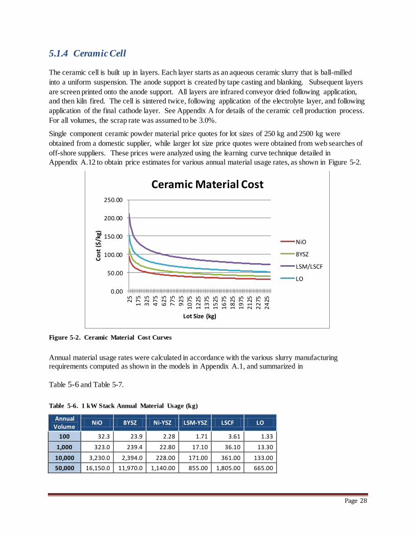

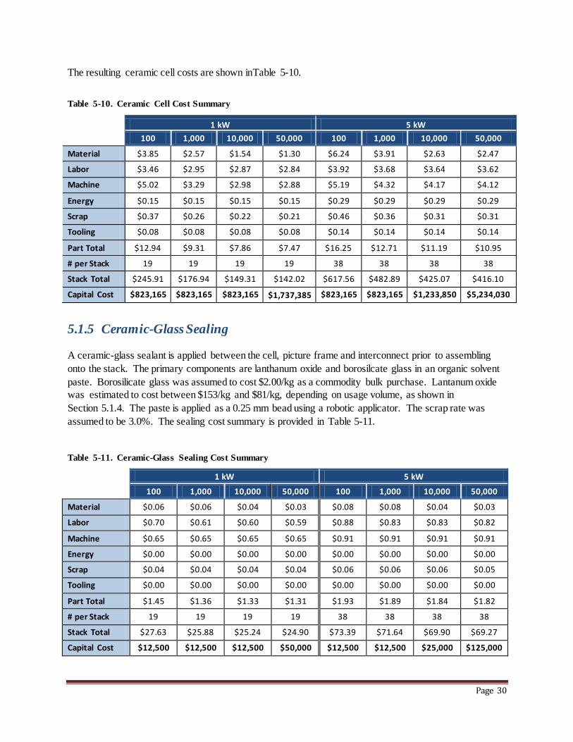


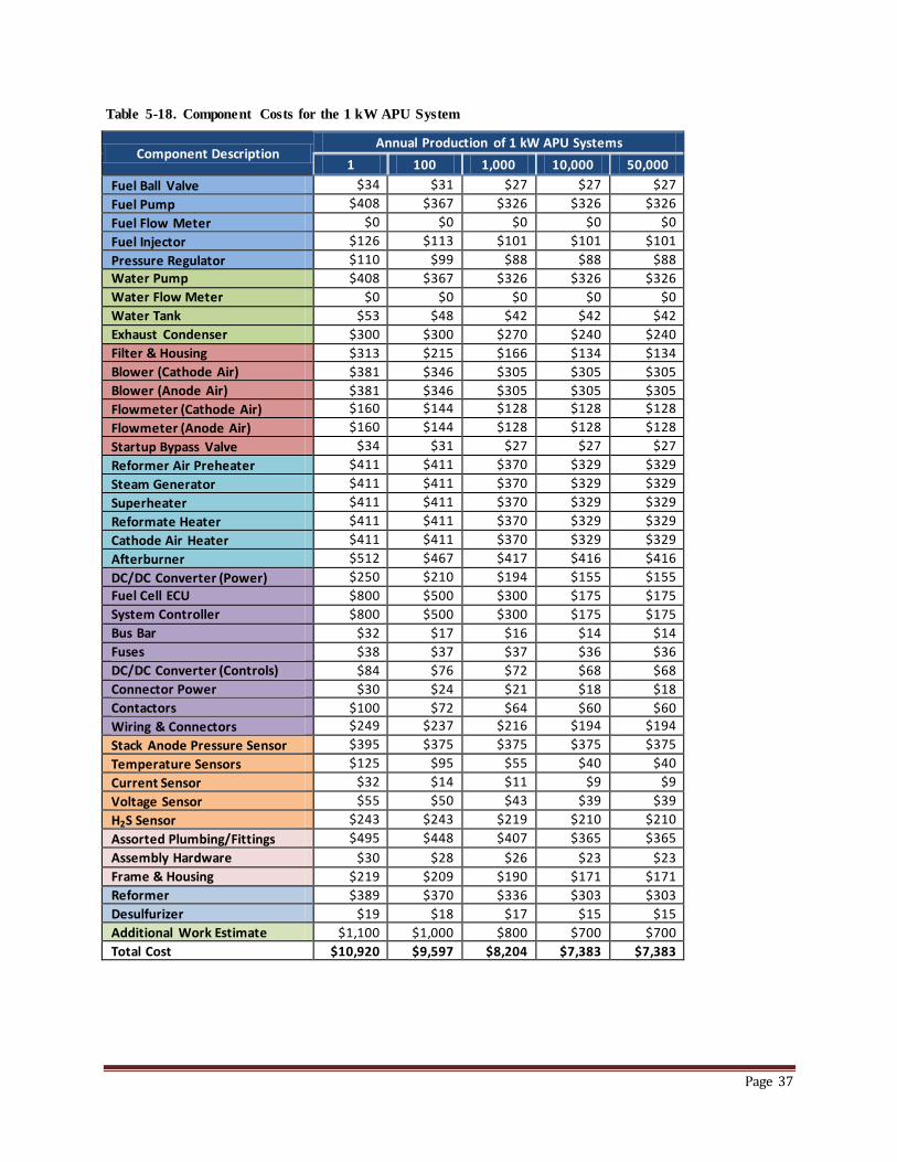


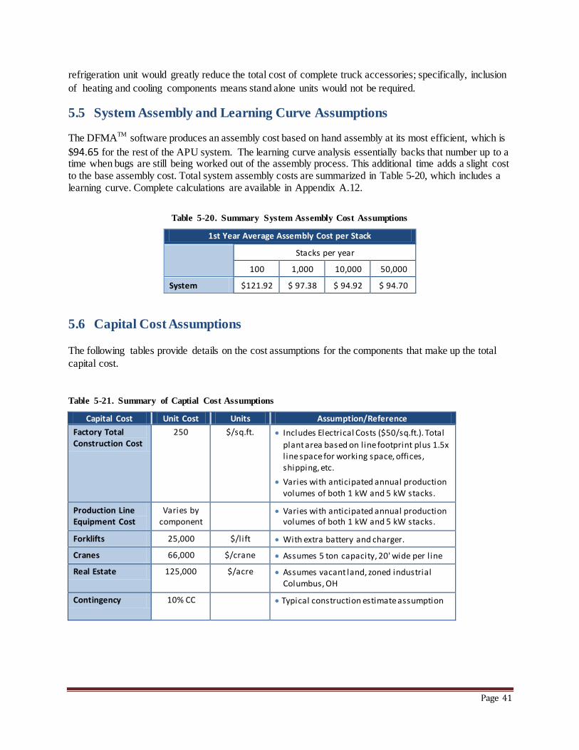


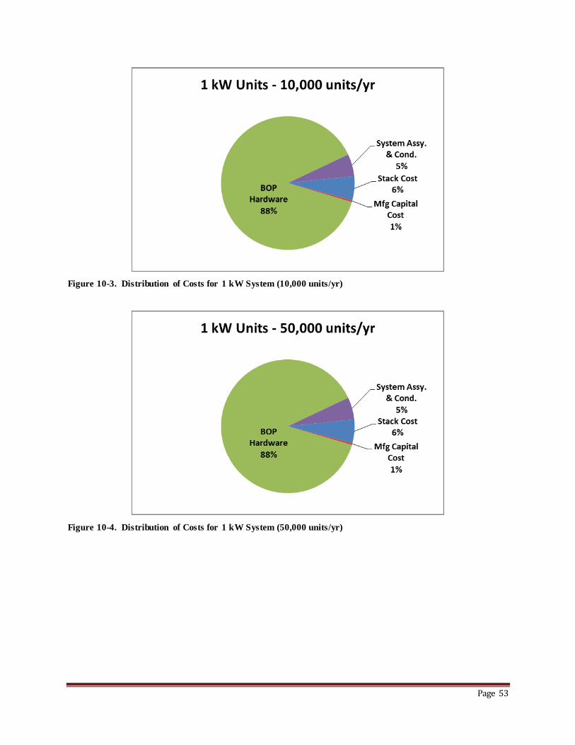


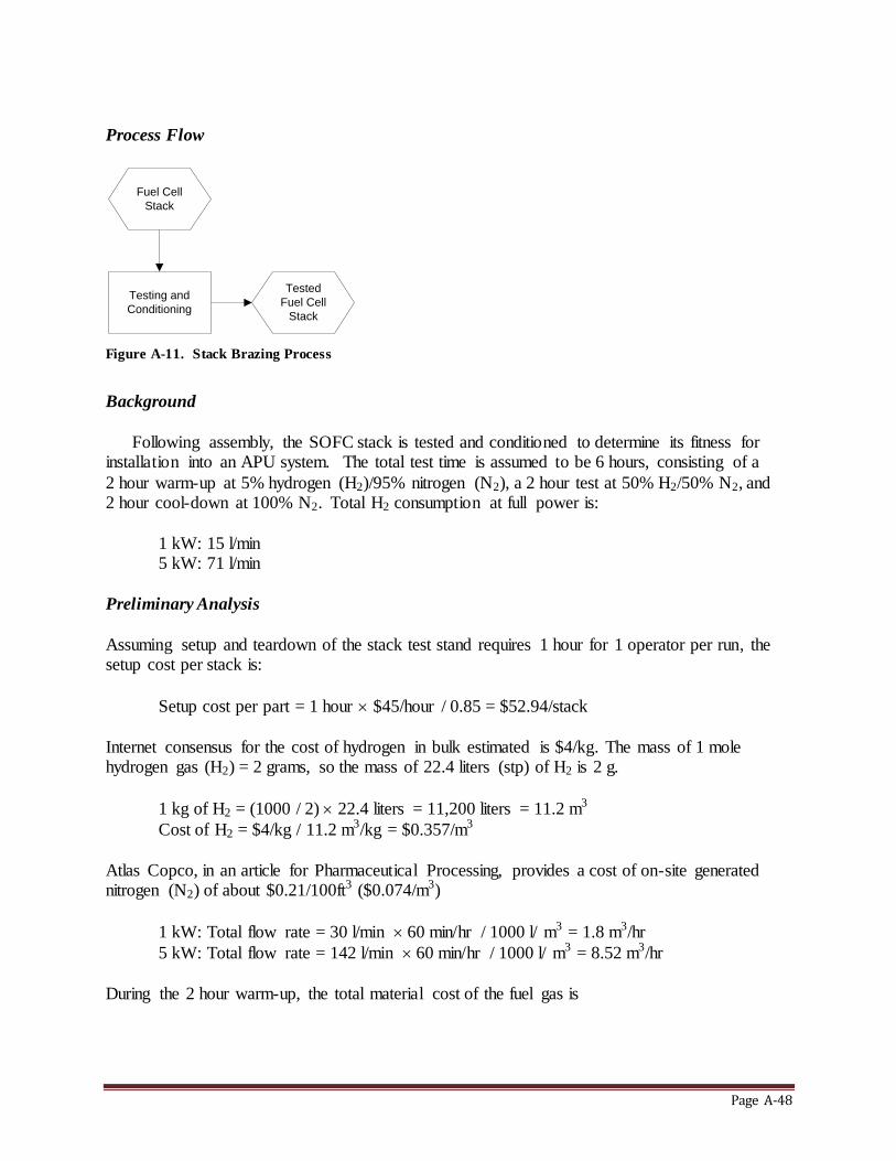


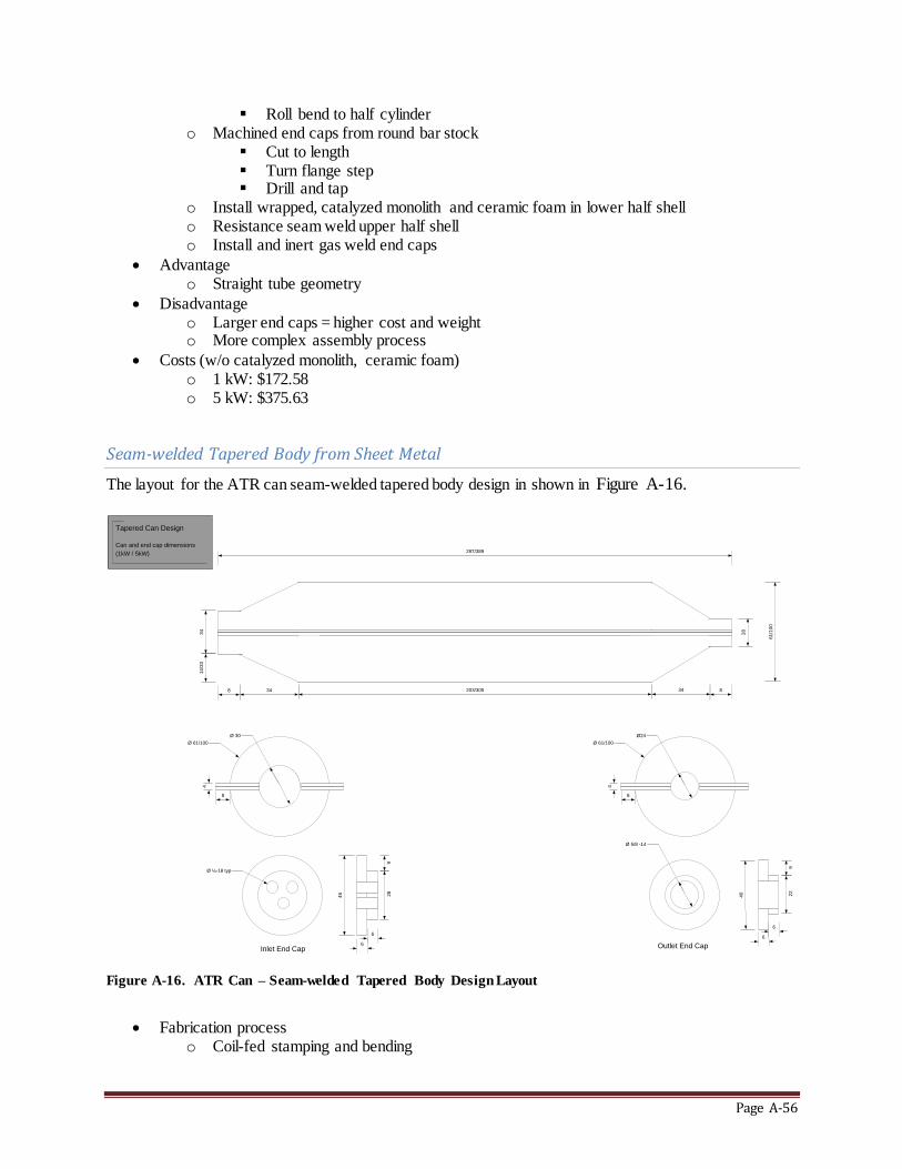
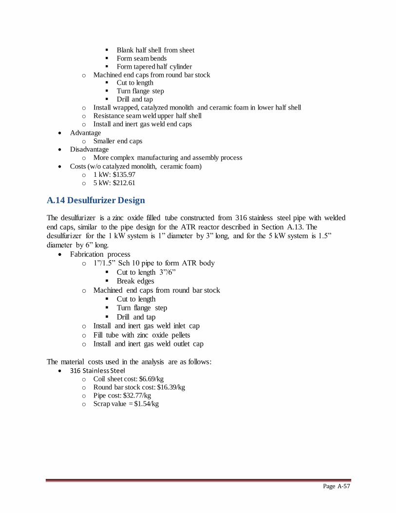


![Solid Oxide Fuel Cell/Gas Turbine Hybrid Cycle Technology ...Fuel Cell (SOFC) gas turbine hybrid system demonstration on a ~200 kW system [2]. This 200 to 500 kW power range overlaps](https://static.documents.pub/doc/80x56/6129f38f7735990dd676cd4b/solid-oxide-fuel-cellgas-turbine-hybrid-cycle-technology-fuel-cell-sofc-gas.jpg)


