Portable Elevator 480 Series Electric Drive MANUFACTURING LLC. 125 King Court • New Holland, PA 17557 717-354-9611 • Fax 717-355-9902 OPERATORS MANUAL Instructions & Parts List Catalog No: PE480ElectricDrive-0408 Date: April 1, 2008 Revised August 15, 2008
Transcript
Portable Elevator480 Series
Electric Drive
MANUFACTURING LLC.
125 King Court • New Holland, PA 17557717-354-9611 • Fax 717-355-9902
OPERATORS MANUALInstructions & Parts List
Catalog No: PE480ElectricDrive-0408Date: April 1, 2008
The Zimmerman line of elevators, manufactured by Zimmerman Manufacturing, LLC. is warranted by said corporation to be free of defects in material and workmanship at time of delivery. This warranty extends for one year from date of purchase, if the unit has been used and serviced in accordance with the recommenda-tions of manufacturer and as stated in the Operator’s Manual.
Obligation under this warranty is limited to replacement or repair of defective parts (based upon satisfactory proof of defect) that are returned freight prepaid to factory.
It is understood that, except for the implied warranty of title, Zimmerman Manufacturing, LLC makes no further warranties, express or implied, except as set forth above. Zimmerman Manufacturing, LLC shall have no obligation or liability of any kind on account of any of its equipment and shall not be liable for spe-cial or consequential damages.
Safety Precaution Definitions
Dangers, Warnings, Cautions, and Notes are used in this manual to emphasize the importance of personal safety, qualifications of operating person-nel, and proper use of the equipment in its intended application. These precautions supplement and/or complement the safety information decals affixed to the unit and include headings that are defined as follows:
Indicates an imminently hazardous situation which, if not avoided, will result in death or serious injury.
Indicates a potentially hazardous situation or practice which, if not avoided, could result in death or serious injury.
Indicates a potentially hazardous situation or practice which, if not avoided, will result in dam-age to equipment and/or minor injury.
In addition to the safety issues above, notes are also used throughout this manual.
2. Commonhardwarenormally�snotsuppl�edwith parts unless specifically requested and chargedaccord�ngly.Non-commonhardware�ssuppl�edand�ncluded�nthepr�ce.
4. Z�mmermanManufactur�ng,LLC�scont�nu-allystr�v�ngto�mprove�tsproducts.Wereservether�ghttomake�mprovementsorchangeswhen�tbecomespract�calandposs�bletodosow�thout�ncurr�nganyobl�gat�ontomakechangesoradd�t�onstothe equipment sold previously.
Always use genuine Zimmerman Manufacturing, LLC Parts.
Precautions
The primary responsibility for safety with the equip-mentbelongstotheoperator.It�sthesk�ll,care,commonsense,andgoodjudgementoftheoperatorthat determines how efficiently and safely the job is performed.Alwaysknowtheoperat�ngcharacter�s-tics of the equipment, including proper set-up and operation, before starting. This equipment must be v�sually�nspectedbeforestart�ng.
Never operate equipment that is not in proper working order with all safety devices in place and operating.
Modification of the equipment, including removal or modification of safety and identifica-tion decals, without the written consent of the manufacturer, is strictly prohibited.
Electrical Precautions
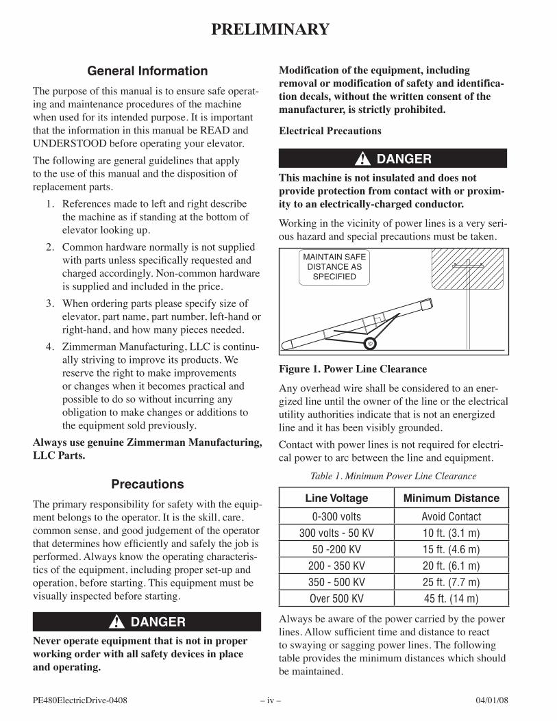
This machine is not insulated and does not provide protection from contact with or proxim-ity to an electrically-charged conductor.
Anyoverheadw�reshallbecons�deredtoanener-g�zedl�neunt�ltheownerofthel�neortheelectr�calut�l�tyauthor�t�es�nd�catethat�snotanenerg�zedl�neand�thasbeenv�s�blygrounded.Contact with power lines is not required for electri-cal power to arc between the line and equipment.
Table 1. Minimum Power Line Clearance
Line Voltage Minimum Distance
0-300 volts Avoid Contact300 volts - 50 KV 10 ft. (3.1 m)
50 -200 KV 15 ft. (4.6 m)200 - 350 KV 20 ft. (6.1 m)350 - 500 KV 25 ft. (7.7 m)Over 500 KV 45 ft. (14 m)
Alwaysbeawareofthepowercarr�edbythepowerlines. Allow sufficient time and distance to react tosway�ngorsagg�ngpowerl�nes.Thefollow�ngtableprov�desthem�n�mumd�stanceswh�chshouldbema�nta�ned.
Neverallowr�dersontheelevatordur�ngoperat�onortransport.Always use a tow vehicle with sufficient weight to supporttheelevator.Iftransport�ngalongpubl�croads,theveh�clemusthaveaGVWRgreaterthanthatoftheelevator.Theh�tchmustalsobeofsufficient capacity to support the tongue weight of theelevator.Alwaysusesafetycha�nswhentransport�ngtheequipment along public roads. It is recommended thatcha�nsalsobeusedwhentransport�ngd�stancesgreaterthanone(1)m�leonnon-publ�croads.Alwayssecuretheh�tchp�nw�thanappropr�atecl�pwhentransport�ng.Alwayslowertheelevatorfullybeforetransport�ng.Theelevatormustberest�ngonthestopswhentransport�ng.Alwaysremovetheopt�onald�rect�onaltroughfromundertheCornD�schargeChutebeforetransport-�ng.Alwayssecuretheelectr�calcordtotheelevatorbeforetransport�ng.
Set-Up Precautions
Nevermaneuvertheelevator�ntotherestr�ctedzonesaroundelectr�calpowerl�nes.Allow sufficient clearance above the elevator for mater�al,suchasbales,toclear.Allowsomeclearancearoundtheelevatorformovementcausedbyv�brat�ons.Alwayschockbothwheelsonboths�desaftertheelevator�spos�t�onandbeforebeg�nn�ngoperat�on.Sw�ngh�tchbackundertheelevatortopreventveh�clesfromcrush�ngtheh�tchclev�s.
Keep hands and fingers clear of the winch and w�nchcablewhenra�s�ngorlower�ngtheelevator.
TheZ�mmermanModel480usesarubberbelttotransportandelevatemater�alsuchasgra�n,sawdust, fertilizer, firewood, and many other types oflooseorgranularmater�al�ntoastoragefac�l�tyortruck.The2-plyrubberbelt�sembossedw�thchevrontreadto"carry"themater�alupan�ncl�ne.Theelevator�sconstructedofgalvan�zedsteelforprotect�onaga�nsttheelementsandmanyofthemater�alshandledontheelevator.Forespec�allycorros�vemater�als,suchasfert�l�zerormanure,theelevatorcanbeconstructedfromsta�nlesssteel.Th�smanual�selectr�callypoweredun�tsonly.
NOTE: That these are general guidelines based on a typical brand. When possible, always look at the specifications for the specific motor being used as the current draw may be different, requiring different conduc-tor sizes. The conductors in the cord must be of sufficient size for the current draw in the motor. Also, the conductor rating may vary depending upon the conductor rating (30°C, 45°C, 65°C) of the cable.
Insufficient conductor/cables may result in overheating which can cause fire.
Wire sizes must be sufficient for the full load currentdrawofthemotor.Besurethew�reused�srated for the full load current draw of the specific motorbe�ngused.
Always follow local, regional and federal regula-tions when connecting electrical circuits. If necessary, consult a local electrical contractor for assistance.
Do not use wire nuts unless the connection is inside a weather-tight enclosure.
Properset-upoftheelevatorshouldbecompletedafter any optional equipment, such as the corn chute,�s�nstalled.
Always move and position the elevator in the lowest position. Raising the elevator changes the center of gravity, increasing the possibility of tipover.
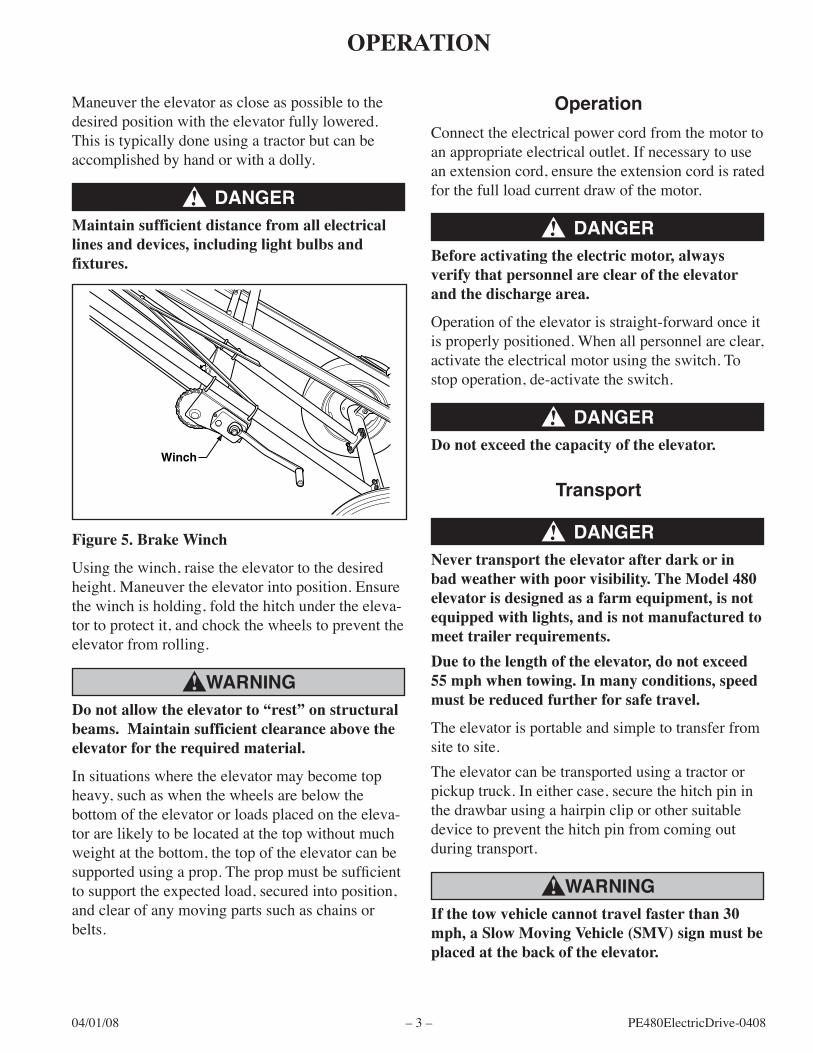
Do not allow the elevator to “rest” on structural beams. Maintain sufficient clearance above the elevator for the required material.
Ins�tuat�onswheretheelevatormaybecometopheavy,suchaswhenthewheelsarebelowthebottomoftheelevatororloadsplacedontheeleva-torarel�kelytobelocatedatthetopw�thoutmuchwe�ghtatthebottom,thetopoftheelevatorcanbesupported using a prop. The prop must be sufficient tosupporttheexpectedload,secured�ntopos�t�on,andclearofanymov�ngpartssuchascha�nsorbelts.
Never transport the elevator after dark or in bad weather with poor visibility. The Model 480 elevator is designed as a farm equipment, is not equipped with lights, and is not manufactured to meet trailer requirements.
Due to the length of the elevator, do not exceed 55 mph when towing. In many conditions, speed must be reduced further for safe travel.
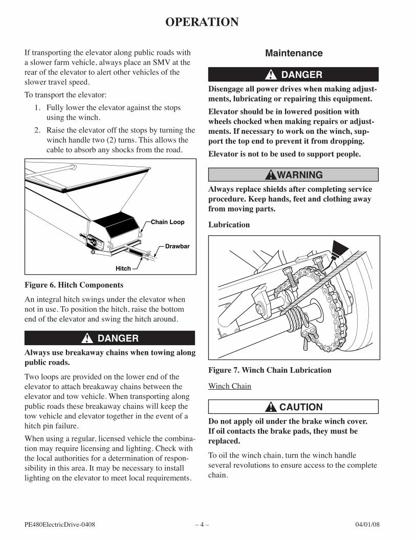
Always use breakaway chains when towing along public roads.
Twoloopsareprov�dedonthelowerendoftheelevatortoattachbreakawaycha�nsbetweentheelevatorandtowveh�cle.Whentransport�ngalongpubl�croadsthesebreakawaycha�nsw�llkeepthetowveh�cleandelevatortogether�ntheeventofah�tchp�nfa�lure.Whenus�ngaregular,l�censedveh�clethecomb�na-tion may require licensing and lighting. Check with thelocalauthor�t�esforadeterm�nat�onofrespon-s�b�l�ty�nth�sarea.Itmaybenecessaryto�nstalllighting on the elevator to meet local requirements.
Maintenance
Disengage all power drives when making adjust-ments, lubricating or repairing this equipment.
Elevator should be in lowered position with wheels chocked when making repairs or adjust-ments. If necessary to work on the winch, sup-port the top end to prevent it from dropping.
Elevator is not to be used to support people.
Always replace shields after completing service procedure. Keep hands, feet and clothing away from moving parts.
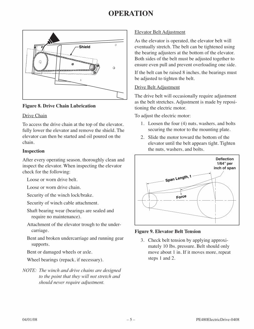
Lubrication
figure 7. Winch Chain Lubrication
W�nchCha�n
Do not apply oil under the brake winch cover. If oil contacts the brake pads, they must be replaced.
Small Hopper 1 3050000 Side, Hopper, Right 1 2 3050002 Side, Hopper, Left 1 3 3050003 End, Hopper 1 4 3120005 Plate, Baffle 1 5 3120003 Rod, Baffle Plate 1 6 LP Pin, Cotter 2 7 0653106 Bolt, Hex Head, 5/16"-18UNC x 3/4" Long 6 8 0653105 Bolt, Truss Head, 5/16"-18UNC x 3/4" Long 4 9 0703703 Washer, Lock, 5/16" 10 10 0603102 Nut, Hex, 5/16"-18UNC 10
LP-Local Purchase
figure 12. Hopper & Related Parts
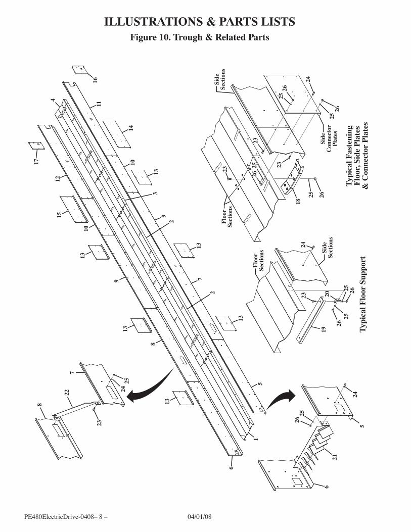
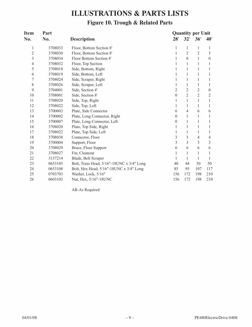
ILLUSTRATIONS & PARTS LISTS
PE480Electr�cDr�ve-0408–14– 04/01/08
figure 13. Belt Slides & Related Parts
61
245
Left Side3
87
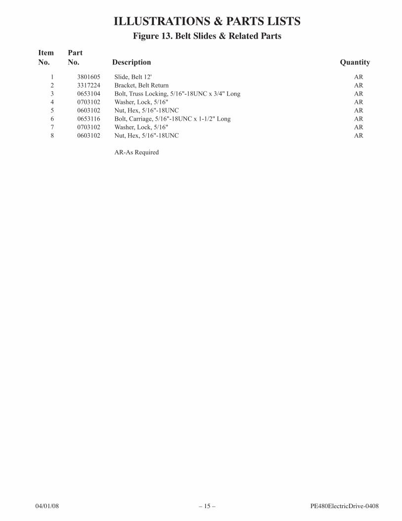
ILLUSTRATIONS & PARTS LISTS
Item No.
Part No. Description Quantity
04/01/08 –15– PE480Electr�cDr�ve-0408
1 3801605 Slide, Belt 12' AR 2 3317224 Bracket, Belt Return AR 3 0653104 Bolt, Truss Locking, 5/16"-18UNC x 3/4" Long AR 4 0703102 Washer, Lock, 5/16" AR 5 0603102 Nut, Hex, 5/16"-18UNC AR 6 0653116 Bolt, Carriage, 5/16"-18UNC x 1-1/2" Long AR 7 0703102 Washer, Lock, 5/16" AR 8 0603102 Nut, Hex, 5/16"-18UNC AR
AR-As Required
figure 13. Belt Slides & Related Parts
ILLUSTRATIONS & PARTS LISTS
PE480Electr�cDr�ve-0408–16– 04/01/08
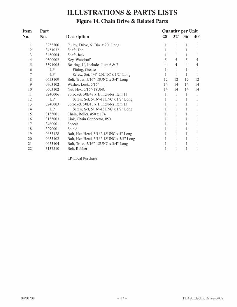
figure 14. Chain Drive & Related Parts
10 9
11
4
12 5910
6
20
7
1
85
22
9
10
18
15
16
17
19
3
4 13
14
10
5
3
5
3
4109
8
Left Side
Right Side
8
9
21
8
2
2
109
ILLUSTRATIONS & PARTS LISTS
Item No.
Part No. Description
Quantity per Unit 28' 32' 36' 40' 44' 48'
04/01/08 –17– PE480Electr�cDr�ve-0408
figure 14. Chain Drive & Related Parts
1 3255500 Pulley, Drive, 6" Dia. x 20" Long 1 1 1 1 2 3451032 Shaft, Top 1 1 1 1 3 3450004 Shaft, Jack 1 1 1 1 4 0500002 Key, Woodruff 5 5 5 5 5 3391005 Bearing, 1", Includes Item 6 & 7 4 4 4 4 6 LP Fitting, Grease 1 1 1 1 7 LP Screw, Set, 1/4"-20UNC x 1/2" Long 1 1 1 1 8 0653109 Bolt, Truss, 5/16"-18UNC x 3/4" Long 12 12 12 12 9 0703102 Washer, Lock, 5/16" 14 14 14 14 10 0603102 Nut, Hex, 5/16"-18UNC 14 14 14 14 11 3240006 Sprocket, 50B48 x 1, Includes Item 11 1 1 1 1 12 LP Screw, Set, 5/16"-18UNC x 1/2" Long 1 1 1 1 13 3240003 Sprocket, 50B13 x 1, Includes Item 13 1 1 1 1 14 LP Screw, Set, 5/16"-18UNC x 1/2" Long 1 1 1 1 15 3135001 Chain, Roller, #50 x 174 1 1 1 1 16 3135003 Link, Chain Connector, #50 1 1 1 1 17 3460001 Spacer 1 1 1 1 18 3290001 Shield 1 1 1 1 19 0653128 Bolt, Hex Head, 5/16"-18UNC x 4" Long 1 1 1 1 20 0653102 Bolt, Hex Head, 5/16"-18UNC x 3/4" Long 1 1 1 1 21 0653104 Bolt, Truss, 5/16"-18UNC x 3/4" Long 1 1 1 1 22 3137510 Belt, Rubber 1 1 1 1
LP-Local Purchase
ILLUSTRATIONS & PARTS LISTS
PE480Electr�cDr�ve-0408–18– 04/01/08
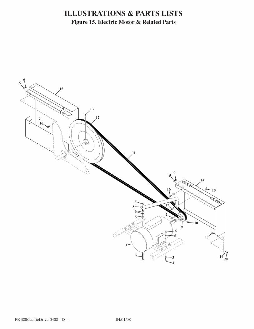
figure 15. Electric Motor & Related PartsILLUSTRATIONS & PARTS LISTS
11
56
15
16
13
12
56
14
1816
68
65 2
910
1756
34
1
7 19 20
17
Item No.
Part No. Description
Quantity per Unit 28' 32' 36' 40' 44' 48'
04/01/08 –19– PE480Electr�cDr�ve-0408
1 3355001 Motor, Electric, 5 HP, Includes Item 2 1 1 1 1 2 0500002 Key 1 1 1 1 3 0703702 Washer, Flat, 3/8" 4 4 4 4 4 0653111 Bolt, Hex Head, 3/8"-16UNC x 1-1/4" Long 4 4 4 4 5 0703703 Washer, Lock, 3/8" AR AR AR AR 6 0603702 Nut, Hex, 3/8"-16UNC AR AR AR AR 7 0653121 Bolt, Hex Head, 5/16"-18UNC x 2-1/2" Long 1 1 1 1 8 3290011 Bracket 1 1 1 1 9 3253001 V-Pulley, BK30, Includes Item 10 1 1 1 1 10 LP Screw, Set, 5/16"-18UNC x 1/2" Long 1 1 1 1 11 3301801 V-Belt, B180 1 0 1 0 3302101 V-Belt, B210 0 1 0 0 3302551 V-Belt, B255 0 0 0 1 12 3251601 V-Pulley, 16 x 1, Includes Item 13 1 1 1 1 13 LP Screw, Set, 5/16"-18UNC x 1/2" Long 1 1 1 1 14 3290003 Shield, Motor Pulley 1 1 1 1 15 3290002 Shield, Jack Shaft Pulley 1 1 1 1 16 0653105 Bolt, Truss Head, 5/16"-18UNC x 3/4" Long 4 4 4 4 17 0652505 Bolt, Hex Head, 1/4"-20UNC x 3/4" Long 2 2 2 2 18 0602504 Nut, Wing, 1/4"-20UNC 1 1 1 1 19 0702501 Washer, Lock, 1/4" 1 1 1 1 20 0602502 Nut, Hex, 1/4"-20UNC 1 1 1 1