A Course Material on Manufacturing Technology - II By Mr. M. MANIKANDAN. ASSIATANT PROFESSOR DEPARTMENT OF MECHANICAL ENGINEERING BHARATHIDASAN ENGINEERING COLLEGE NATRAMPALLI-635 854 BEC 1 Department of Mechanical Engineering
Transcript
A Course Material on
Manufacturing Technology - II
By
Mr. M. MANIKANDAN.
ASSIATANT PROFESSOR
DEPARTMENT OF MECHANICAL ENGINEERING BHARATHIDASAN ENGINEERING COLLEGE
NATRAMPALLI-635 854
BEC 1 Department of Mechanical Engineering
CONTENTS
SL.
NO.
TOPICS PAGE
NO.
i SYLLABUS 5
1 UNIT – I
THEORY OF METAL CUTTING
6
1.1 MECHANICS OF CHIP FORMATION 6
1.2 SINGLE-POINT CUTTING TOOL 6
1.3 FORCES IN MACHINING 7
1.4 TYPES OF CHIP 8
1.5 CUTTING TOOL NOMENCLATURE 10
1.6 ORTHOGONAL METAL CUTTING 11
1.7 THERMAL ASPECTS 12
1.8 CUTTING TOOL MATERIALS 13
1.9 TOOL WEAR AND TOOL LIFE 15
1.10 SURFACE FINISH 16
1.11 CUTTING FLUIDS 17
1.12 MACHINABILITY 19
2 UNIT - II
TURNING MACHINES
21
2.1 CENTER LATHES 21
2.2 TAPER TURNING METHODS 22
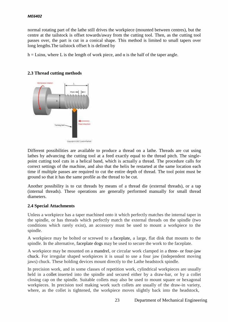
2.3 THREAD CUTTING METHODS 23
2.4 SPECIAL ATTACHMENTS 23
2.5 MACHINING TIME 24
2.6 CAPSTAN VERSUS TURRET 24
2.7 SEMI-AUTOMATIC 25
2.8 AUTOMATIC 25
3 UNIT - III
SHAPER, MILLING AND GEAR CUTTING MACHINES
26
3.1 SHAPERS 26
3.2 TYPES OF SHAPERS 26
3.3 DRILLING AND REAMING 27
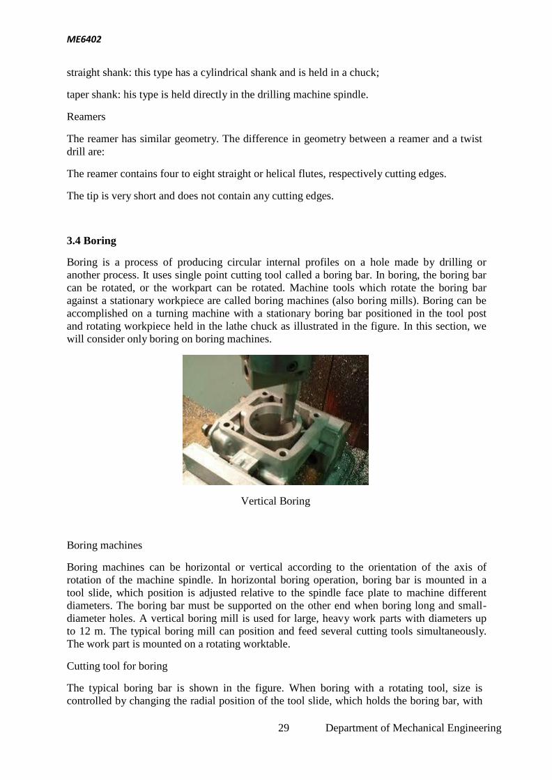
3.4 BORING 29
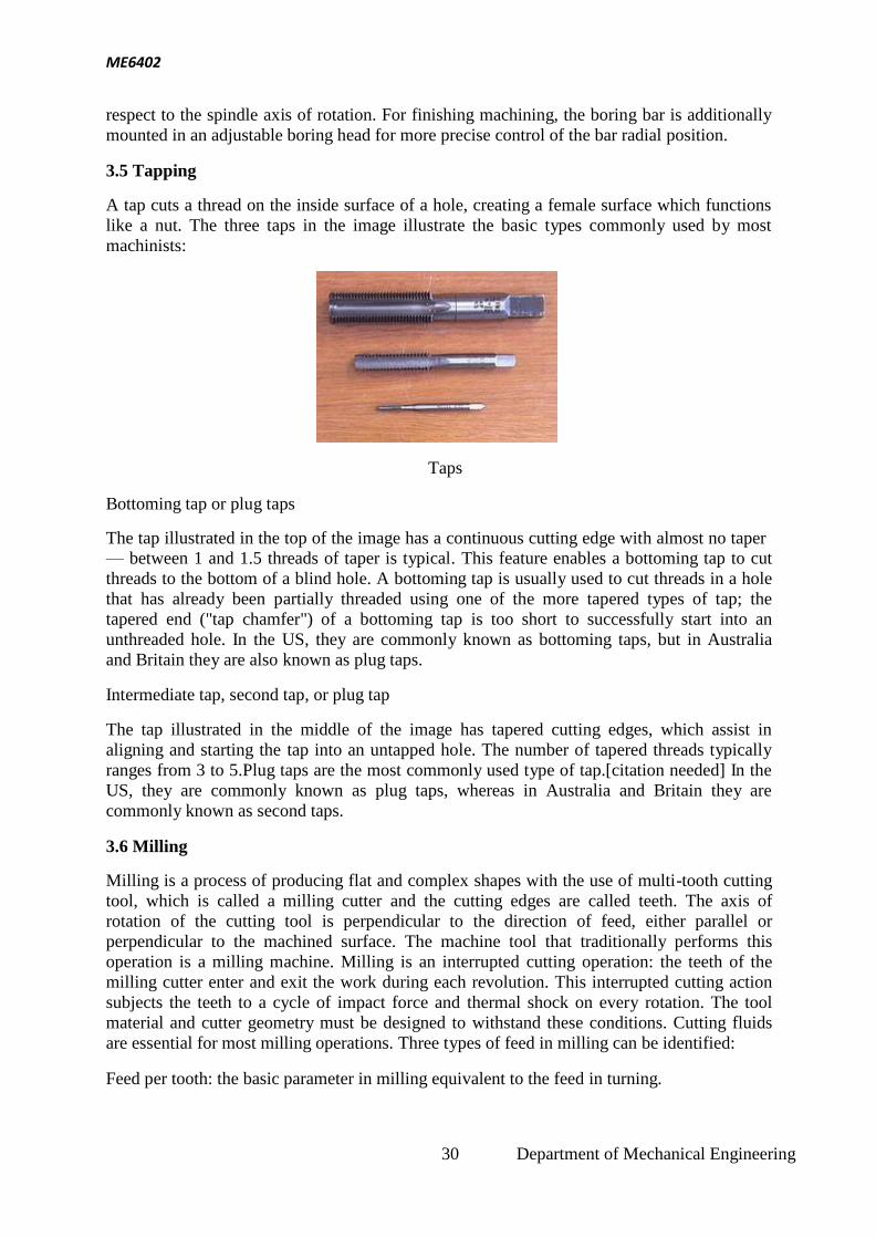
3.5 TAPPING 30
3.6 MILLING 30
3.7 GEAR 33
3.8 GEAR MILLING 33
3.9 GEAR HOBBING 34
3.10 SHAPING WITH A PINION-SHAPED CUTTER 34
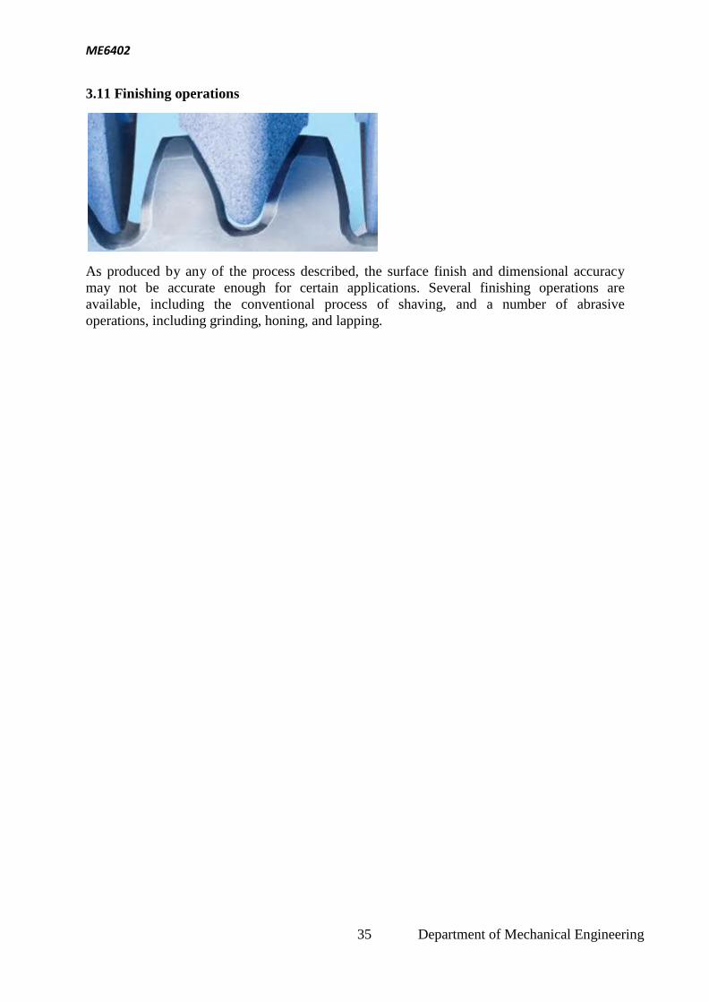
3.11 FINISHING OPERATIONS 35
4 UNIT - IV
ABRASIVE PROCESS AND BROACHING
36
4.1 ABRASIVE PROCESSES 36
4.2 GRINDING WHEELS 36
BEC 3 Department of Mechanical Engineering
4.3 TYPES OF GRINDING PROCESSES 38
4.4 CYLINDRICAL GRINDING 39
4.5 OUTSIDE DIAMETER GRINDING 40
4.6 CENTERLESS GRINDING 43
4.7 INTERNAL GRINDING 43
4.8 CONCEPTS OF SURFACE INTEGRITY 44
4.9 BROACHING MACHINES 45
4.10 PUSH TYPE BROACHING MACHINE 45
4.11 PULL TYPE BROACHING MACHINE 46
4.12 SURFACE BROACHES 47
4.13 CONTINUOUS CHAIN BROACHING 47
5 UNIT -V
CNC MACHINES
49
5.1 NUMERICAL CONTROL (NC) MACHINE TOOLS 49
5.2 TYPES OF NC SYSTEMS 49
5.3 PROGRAMMING FUNDAMENTALS CNC 53
5.4 MANUAL PART PROGRAMMING 57
5.5 MICROMACHINING 63
5.6 WATER MACHINING 64
6
QUESTION BANK 67
7
2 MARKS QUESTIONS AND ANSWERS 72
8 UNIVERSITY MODEL QUESTIONS 111
BEC 4 Department of Mechanical Engineering
ME6402 MANUFACTURING TECHNOLOGY – II L T P C
3 0 0 3 OBJECTIVES:
To understand the concept and basic mechanics of metal cutting, working of standard machine tools such as lathe, shaping and allied machines, milling, drilling and allied machines, grinding and allied machines and broaching.
To understand the basic concepts of Computer Numerical Control (CNC) of machine tools and CNC
Programming
UNIT I THEORY OF METAL CUTTING 9
Mechanics of chip formation, single point cutting tool, forces in machining, Types of chip, cutting tools –
nomenclature, orthogonal metal cutting, thermal aspects, cutting tool materials, tool wear, tool life, surface finish, cutting fluids and Machinability.
UNIT II TURNING MACHINES 9
Centre lathe, constructional features, specification, operations – taper turning methods, thread cutting methods, special attachments, machining time and power estimation. Capstan and turret lathes- tool layout – automatic lathes: semi automatic – single spindle : Swiss type, automatic screw type – multi spindle:
UNIT III SHAPER, MILLING AND GEAR CUTTING MACHINES 9 Shaper - Types of operations. Drilling ,reaming, boring, Tapping. Milling operations-types of milling
cutter. Gear cutting – forming and generation principle and construction of gear milling ,hobbing and gear
shaping processes –finishing of gears.
UNIT IV ABRASIVE PROCESS AND BROACHING 9 Abrasive processes: grinding wheel – specifications and selection, types of grinding process– cylindrical
grinding, surface grinding, centreless grinding and internal grinding- Typical applications – concepts of surface integrity, broaching machines: broach construction – push, pull, surface and continuous broaching
machines
UNIT V CNC MACHINING 9 Numerical Control (NC) machine tools – CNC types, constructional details, special features, machining centre, part programming fundamentals CNC – manual part programming –
micromachining – wafer machining
TOTAL : 45 PERIODS
OUTCOME:
Upon completion of this course, the students can able to understand and compare the functions and applications of different metal cutting tools and also demonstrate the programming in CNC machining.
TEXT BOOKS:
1. Hajra Choudhury, "Elements of Workshop Technology", Vol.II., Media Promoters
2. Rao. P.N “Manufacturing Technology - Metal Cutting and Machine Tools", Tata McGraw-Hill, New Delhi, 2003.
REFERENCES: 1. Richerd R Kibbe, John E. Neely, Roland O. Merges and Warren J.White “Machine Tool
Practices”, Prentice Hall of India, 1998 2. HMT, "Production Technology", Tata McGraw Hill, 1998. 3. Geofrey Boothroyd, "Fundamentals of Metal Machining and Machine Tools", Mc Graw Hill,
1984 4. Roy. A.Lindberg, “Process and Materials of Manufacture,” Fourth Edition, PHI/Pearson Education 2006.
BEC 5 Department of Mechanical Engineering
ME6402
Definitions
UNIT I
THEORY OF METAL CUTTING
Machining: Term applied to all material-removal processes
Metal cutting: The process in which a thin layer of excess metal (chip) is removed by a
wedge-shaped single-point or multipoint cutting tool with defined geometry from a work
piece, through a process of extensive plastic deformation
1.1 MECHANICS OF CHIP FORMATION
The cutting itself is a process of extensive plastic deformation to form a chip that is removed
afterward. The basic mechanism of chip formation is essentially the same for all machining
operations. Assuming that the cutting action is continuous, we can develop so-called
continuous model of cutting process.
The cutting model shown above is oversimplified. In reality, chip formation occurs not
in a plane but in so-called primary and secondary shear zones, the first one between the cut
and chip, and the second one along the cutting tool face.
1.2 Single-point cutting tool,
As distinguished from other cutting tools such as a The cutting edge is ground to suit
a particular machining operation and may be re sharpened or reshaped as needed. The ground
tool bit is held rigidly by a tool holder while it is cutting. Back Rake is to help control the direction of the chip, which naturally curves into the work
due to the difference in length from the outer and inner parts of the cut. It also helps
counteract the pressure against the tool from the work by pulling the tool into the work.
Side Rake along with back rake controls the chip flow and partly counteracts the resistance
of the work to the movement of the cutter and can be optimized to suit the particular material
being cut. Brass for example requires a back and side rake of 0 degrees while aluminum uses
a back rake of 35 degrees and a side rake of 15 degrees. Nose Radius makes the finish of the
cut smoother as it can overlap the previous cut and eliminate the peaks and valleys that a
BEC 6 Department of Mechanical Engineering
ME6402
pointed tool produces. Having a radius also strengthens the tip, a sharp point being quite
fragile.
All the other angles are for clearance in order that no part of the tool besides the actual
cutting edge can touch the work. The front clearance angle is usually 8 degrees while the side
clearance angle is 10-15 degrees and partly depends on the rate of feed expected.
Minimum angles which do the job required are advisable because the tool gets weaker as the
edge gets keener due to the lessening support behind the edge and the reduced ability to
absorb heat generated by cutting.
The Rake angles on the top of the tool need not be precise in order to cut but to cut
efficiently there will be an optimum angle for back and side rake.
1.3 Forces in machining
If you make a free body analysis of the chip, forces acting on the chip would be as follows.
At cutting tool side due to motion of chip against tool there will be a frictional force and a
normal force to support that. At material side thickness of the metal increases while it flows
from uncut to cut portion. This thickness increase is due to inter planar slip between different
metal layers. There should be a shear force (Fs) to support this phenomenon. According
to shear plane theory this metal layer slip happens at single plane called shear plane. So
shear force acts on shear plane. Angle of shear plane can approximately determined
using shear plane theory analysis. It is as follows
7 Department of Mechanical Engineering
ME6402
Forces acting on the chip on tool side and shear plane side
Shear force on shear plane can be determined using shear strain rate and properties of
material. A normal force (Fn) is also present perpendicular to shear plane. The resultant force
(R) at cutting tool side and metal side should balance each other in order to make the chip in
equilibrium. Direction of resultant force, R is determined as shown in Figure.
1.4 Types of chip
There are three types of chips that are commonly produced in cutting,
Discontinuous chips
Continuous chips
Continuous chips with built up edge
A discontinuous chip comes off as small chunks or particles. When we get this chip it may
indicate,
Brittle work material
Small or negative rake angles
Coarse feeds and low speeds
A continuous chip looks like a long ribbon with a smooth shining surface. This chip type
may indicate,
Ductile work materials
Large positive rake angles
8 Department of Mechanical Engineering
ME6402
Fine feeds and high speeds
Continuous chips with a built up edge still look like a long ribbon, but the surface is no
longer smooth and shining. Under some circumstances (low cutting speeds of ~0.5 m/s,
small or negative rake angles),
Work materials like mild steel, aluminum, cast iron, etc., tend to develop so-called built-up
edge, a very hardened layer of work material attached to the tool face, which tends to act as a
cutting edge itself replacing the real cutting tool edge. The built-up edge tends to grow until
it reaches a critical size (~0.3 mm) and then passes off with the chip, leaving small fragments
on the machining surface. Chip will break free and cutting forces are smaller, but the effects
is a rough machined surface. The built-up edge disappears at high cutting speeds.
Chip control
Discontinuous chips are generally desired because
They are less dangerous for the operator
Do not cause damage to workpiece surface and machine tool
Can be easily removed from the work zone
Can be easily handled and disposed after machining.
There are three principle methods to produce the favourable discontinuous chip:
Proper selection of cutting conditions
Use of chip breakers
Change in the work material properties
Chip breaker
Chip break and chip curl may be promoted by use of a so-called chip breaker. There are two
types of chip breakers
External type, an inclined obstruction clamped to the tool face
Integral type, a groove ground into the tool face or bulges formed onto the tool face
9 Department of Mechanical Engineering
ME6402
1.5 Cutting tool nomenclature
Back Rake is to help control the direction of the chip, which naturally curves into the work
due to the difference in length from the outer and inner parts of the cut. It also helps
counteract the pressure against the tool from the work by pulling the tool into the work.
Side Rake along with back rake controls the chip flow and partly counteracts the resistance
of the work to the movement of the cutter and can be optimized to suit the particular material
being cut. Brass for example requires a back and side rake of 0 degrees while aluminum uses
a back rake of 35 degrees and a side rake of 15 degrees.
Nose Radius makes the finish of the cut smoother as it can overlap the previous cut and
eliminate the peaks and valleys that a pointed tool produces. Having a radius also strengthens
the tip, a sharp point being quite fragile.
All the other angles are for clearance in order that no part of the tool besides the actual
cutting edge can touch the work. The front clearance angle is usually 8 degrees while the side
clearance angle is 10-15 degrees and partly depends on the rate of feed expected.
Minimum angles which do the job required are advisable because the tool gets weaker as the
edge gets keener due to the lessening support behind the edge and the reduced ability to
absorb heat generated by cutting.
The Rake angles on the top of the tool need not be precise in order to cut but to cut
efficiently there will be an optimum angle for back and side rake.
10 Department of Mechanical Engineering
ME6402
1.6 Orthogonal metal cutting
Orthogonal metal cutting
Oblique metal cutting
Cutting edge of the tool is
perpendicular to the direction
of tool travel.
The cutting edge is inclined
at an angle less than 90o
to
the direction of tool travel.
The direction of chip flow is
perpendicular to the cutting
edge.
The chip flows on the tool
face making an angle.
The chip coils in a tight flat
spiral
The chip flows side ways in
a long curl.
For same feed and depth of
cut the force which shears
the metal acts on smaller
areas. So the life of the tool
is less.
The cutting force acts on
larger area and so tool life is
more.
Produces sharp corners.
Produces a chamfer at the
end of the cut
Smaller length of cutting
edge is in contact with the
work.
For the same depth of cut
greater length of cutting edge
is in contact with the work.
Generally parting off in
lathe, broaching and slotting
operations are done in this
method.
This method of cutting is
used in almost all machining
operations.
Depending on whether the stress and deformation in cutting occur in a plane (two-
dimensional case) or in the space (three-dimensional case), we consider two principle types
of cutting:
11 Department of Mechanical Engineering
ME6402
Orthogonal cutting the cutting edge is straight and is set in a position that is perpendicular to
the direction of primary motion. This allows us to deal with stresses and strains that act in a
plane.
Oblique cutting the cutting edge is set at an angle.
According to the number of active cutting edges engaged in cutting, we distinguish again two
types of cutting:
Single-point cutting the cutting tool has only one major cutting edge
Examples: turning, shaping, boring
Multipoint cutting the cutting tool has more than one major cutting edge
Examples: drilling, milling, broaching, reaming. Abrasive machining is by definition a
process of multipoint cutting.
Cutting conditions
Each machining operation is characterized by cutting conditions, which comprises a set of
three elements:
Cutting velocity: The traveling velocity of the tool relative to the work piece. It is measured
in m/s or m/min.
Depth of cut: The axial projection of the length of the active cutting tool edge, measured in
mm. In orthogonal cutting it is equal to the actual width of cut.
Feed: The relative movement of the tool in order to process the entire surface of the work
piece. In orthogonal cutting it is equal to the thickness of cut and is measured in mm.
1.7 Thermal aspects
In cutting, nearly all of energy dissipated in plastic deformation is converted into heat that in
turn raises the temperature in the cutting zone. Since the heat generation is closely related to
the plastic deformation and friction, we can specify three main sources of heat when cutting,
Plastic deformation by shearing in the primary shear zone
Plastic deformation by shearing and friction on the cutting face
Friction between chip and tool on the tool flank
Heat is mostly dissipated by,
The discarded chip carries away about 60~80% of the total heat
The workpiece acts as a heat sink drawing away 10~20% heat
12 Department of Mechanical Engineering
ME6402
The cutting tool will also draw away ~10% heat
If coolant is used in cutting, the heat drawn away by the chip can be as big as 90% of the
total heat dissipated. Knowledge of the cutting temperature is important because it:
Affects the wear of the cutting tool. Cutting temperature is the primary factor affecting the
cutting tool wear can induce thermal damage to the machined surface. High surface
temperatures promote the process of oxidation of the machined surface. The oxidation layer
has worse mechanical properties than the base material, which may result in shorter service
life. Causes dimensional errors in the machined surface. The cutting tool elongates as a result
of the increased temperature, and the position of the cutting tool edge shifts toward the
machined surface, resulting in a dimensional error of about 0.01~0.02 mm. Since the
processes of thermal generation, dissipation, and solid body thermal deformation are all
transient, some time is required to achieve a steady-state condition
Cutting temperature determination
Cutting temperature is either measured in the real machining process, or predicted in the
machining process design. The mean temperature along the tool face is measured directly by
means of different thermocouple techniques, or indirectly by measuring the infrared
radiation, or examination of change in the tool material microstructure or micro hardness
induced by temperature. Some recent indirect methods are based on the examination of the
temper color of a chip, and on the use of thermo sensitive paints.
There are no simple reliable methods of measuring the temperature field. Therefore,
predictive approaches must be relied on to obtain the mean cutting temperature and
temperature field in the chip, tool and work piece.
For cutting temperature prediction, several approaches are used:
Analytical methods: there are several analytical methods to predict the mean temperature.
The interested readers are encouraged to read more specific texts, which present in detail
these methods. Due to the complex nature of the metal cutting process, the analytical
methods are typically restricted to the case of orthogonal cutting.
Numerical methods: These methods are usually based on the finite element modeling of
metal cutting. The numerical methods, even though more complex than the analytical
approaches, allow for prediction not only of the mean cutting temperature along the tool face
but also the temperature field in orthogonal and oblique cutting.
1.8 Cutting tool materials
Requirements
The cutting tool materials must possess a number of important properties to avoid excessive
wear, fracture failure and high temperatures in cutting, the following characteristics are
essential for cutting materials to withstand the heavy conditions of the cutting process and to
produce high quality and economical parts:
13 Department of Mechanical Engineering
ME6402
Hardness at elevated temperatures (so-called hot hardness) so that hardness and strength of
the tool edge are maintained in high cutting temperatures:
Toughness: ability of the material to absorb energy without failing. Cutting if often
accompanied by impact forces especially if cutting is interrupted, and cutting tool may fail
very soon if it is not strong enough.
Wear resistance: although there is a strong correlation between hot hardness and wear
resistance, later depends on more than just hot hardness. Other important characteristics
include surface finish on the tool, chemical inertness of the tool material with respect to the
work material, and thermal conductivity of the tool material, which affects the maximum
value of the cutting temperature at tool-chip interface.
Cutting tool materials
Carbon Steels
It is the oldest of tool material. The carbon content is 0.6~1.5% with small quantities of
silicon, Chromium, manganese, and vanadium to refine grain size. Maximum hardness is
about HRC 62. This material has low wear resistance and low hot hardness. The use of these
materials now is very limited.
High-speed steel (HSS)
First produced in 1900s. They are highly alloyed with vanadium, cobalt, molybdenum,
tungsten and Chromium added to increase hot hardness and wear resistance. Can be
hardened to various depths by appropriate heat treating up to cold hardness in the range of
HRC 63-65. The cobalt component give the material a hot hardness value much greater than
carbon steels. The high toughness and good wear resistance make HSS suitable for all type
of cutting tools with complex shapes for relatively low to medium cutting speeds. The most
widely used tool material today for taps, drills, reamers, gear tools, end cutters, slitting,
broaches, etc.
Cemented Carbides
Introduced in the 1930s. These are the most important tool materials today because of their
high hot hardness and wear resistance. The main disadvantage of cemented carbides is their
low toughness. These materials are produced by powder metallurgy methods, sintering grains
of tungsten carbide (WC) in a cobalt (Co) matrix (it provides toughness). There may be other
carbides in the mixture, such as titanium carbide (TiC) and/or tantalum carbide (TaC) in
addition to WC.
Ceramics
Ceramic materials are composed primarily of fine-grained, high-purity aluminum oxide
(Al2O3), pressed and sintered with no binder. Two types are available:
White, or cold-pressed ceramics, which consists of only Al2O3 cold pressed into inserts and
sintered at high temperature.
Black, or hot-pressed ceramics, commonly known as cermets (from ceramics and metal).
This material consists of 70% Al2O3 and 30% TiC. Both materials have very high wear
resistance but low toughness; therefore they are suitable only for continuous operations such
14 Department of Mechanical Engineering
ME6402
as finishing turning of cast iron and steel at very high speeds. There is no occurrence of built-
up edge, and coolants are not required.
Cubic boron nitride (CBN) and synthetic diamonds
Diamond is the hardest substance ever known of all materials. It is used as a coating material
in its polycrystalline form, or as a single-crystal diamond tool for special applications, such
as mirror finishing of non-ferrous materials. Next to diamond, CBN is the hardest tool
material. CBN is used mainly as coating material because it is very brittle. In spite of
diamond, CBN is suitable for cutting ferrous materials.
1.9 Tool wear and tool life
The life of a cutting tool can be terminated by a number of means, although they fall broadly
into two main categories:
Gradual wearing of certain regions of the face and flank of the cutting tool, and abrupt tool
failure. Considering the more desirable case Πthe life of a cutting tool is therefore
determined by the amount of wear that has occurred on the tool profile and which reduces
the efficiency of cutting to an unacceptable level, or eventually causes tool failure. When the
tool wear reaches an initially accepted amount, there are two options,
To resharpen the tool on a tool grinder, or
To replace the tool with a new one.
This second possibility applies in two cases,
When the resource for tool resharpening is exhausted. or
The tool does not allow for resharpening, e.g. in case of the indexable carbide inserts
Wear zones
Gradual wear occurs at three principal locations on a cutting tool. Accordingly, three main
types of tool wear can be distinguished,
Crater wear
Flank wear
Corner wear
Crater wear: consists of a concave section on the tool face formed by the action of the chip
sliding on the surface. Crater wear affects the mechanics of the process increasing the actual
rake angle of the cutting tool and consequently, making cutting easier. At the same time, the
crater wear weakens the tool wedge and increases the possibility for tool breakage. In
general, crater wear is of a relatively small concern.
Flank wear: occurs on the tool flank as a result of friction between the machined surface of
the workpiece and the tool flank. Flank wear appears in the form of so-called wear land and
is measured by the width of this wear land, VB, Flank wear affects to the great extend the
mechanics of cutting. Cutting forces increase significantly with flank wear. If the amount of
flank wear exceeds some critical value (VB > 0.5~0.6 mm), the excessive cutting force may
cause tool failure.
15 Department of Mechanical Engineering
ME6402
Corner wear: occurs on the tool corner. Can be considered as a part of the wear land and
respectively flank wear since there is no distinguished boundary between the corner wear and
flank wear land. We consider corner wear as a separate wear type because of its importance
for the precision of machining. Corner wear actually shortens the cutting tool thus increasing
gradually the dimension of machined surface and introducing a significant dimensional error
in machining, which can reach values of about 0.03~0.05 mm.
Tool life
Tool wear is a time dependent process. As cutting proceeds, the amount of tool wear
increases gradually. But tool wear must not be allowed to go beyond a certain limit in order
to avoid tool failure. The most important wear type from the process point of view is the
flank wear, therefore the parameter which has to be controlled is the width of flank wear
land, VB. This parameter must not exceed an initially set safe limit, which is about 0.4 mm
for carbide cutting tools. The safe limit is referred to as allowable wear land (wear criterion),
. The cutting time required for the cutting tool to develop a flank wear land of width is called
tool life, T, a fundamental parameter in machining. The general relationship of VB versus
cutting time is shown in the figure (so-called wear curve). Although the wear curve shown is
for flank wear, a similar relationship occurs for other wear types. The figure shows also how
to define the tool life T for a given wear criterion VBk
Parameters, which affect the rate of tool wear, are
intergranular attack, and hydrogen embrittlement. When a traditional manufacturing process
is used, such as machining, the surface layer sustains local plastic deformation.
The processes that affect surface integrity can be conveniently broken up into three
classes: traditional processes, non-traditional processes, and finishing treatments. Traditional
processes are defined as processes where the tool contacts the workpiece surface; for
example: grinding, turning, and machining. These processes will only damage the surface
integrity if the improper parameters are used, such as dull tools, too high feed speeds,
improper coolant or lubrication, or incorrect grinding wheel hardness. Nontraditional
processes are defined as processes where the tool does not contact the workpiece; examples
of this type of process include EDM, electrochemical machining, and chemical milling.
These processes will produce different surface integrity depending on how the processes are
controlled; for instance, they can leave a stress-free surface, a remelted surface, or excessive
surface roughness. Finishing treatments are defined as processes that negate surface finishes
imparted by traditional and non-traditional processes or improve the surface integrity. For
example, compressive residual stress can be enhanced via peening or roller burnishing or the
recast layer left by EDMing can be removed via chemical milling.
Finishing treatments can affect the workpiece surface in a wide variety of manners. Some
clean and/or remove defects, such as scratches, pores, burrs, flash, or blemishes. Other
processes improve or modify the surface appearance by improving smoothness, texture, or
color. They can also improve corrosion resistance,wear resistance, and/or
reduce friction. Coatings are another type of finishing treatment that may be used to plate an
expensive or scarce material onto a less expensive base material.
Variables
Manufacturing processes have five main variables: the workpiece, the tool, the machine
tool, the environment, and process variables. All of these variables can affect the surface
integrity of the workpiece by producing:
44 Department of Mechanical Engineering
ME6402
High temperatures involved in various machining processes
Plastic deformation in the workpiece (residual stresses)
Surface geometry (roughness, cracks, distortion)
Chemical reactions, especially between the tool and the workpiece
4.9 Broaching Machines
Broaching machines are relatively simple as they only have to move the broach in a
linear motion at a predetermined speed and provide a means for handling the broach
automatically. Most machines are hydraulic, but a few specialty machines are
mechanically driven. The machines are distinguished by whether their motion is
horizontal or vertical. The choice of machine is primarily dictated by the stroke
required. Vertical broaching machines rarely have a stroke longer than 60 in (1.5 m).
Vertical broaching machines can be designed for push broaching, pull-down
broaching, pull-up broaching, or surface broaching. Push broaching machines are
similar to an arbor press with a guided ram; typical capacities are 5 to 50 tons. The
two ram pull-down machine is the most common type of broaching machine. This
style machine has the rams under the table. Pull-up machines have the ram above the
table; they usually have more than one ram. Most surface broaching is done on a
vertical machine.
Horizontal broaching machines are designed for pull broaching, surface broaching,
continuous broaching, and rotary broaching. Pull style machines are basically vertical
machines laid on the side with a longer stroke. Surface style machines hold the
broach stationary while the workpieces are clamped into fixtures that are mounted on
a conveyor system. Continuous style machines are similar to the surface style
machines except adapted for internal broaching.
Horizontal machines used to be much more common than vertical machines, however
today they represent just 10% of all broaching machines purchased. Vertical
machines are more popular because they take up less space.
4.10 Push Type Broaching Machine
45 Department of Mechanical Engineering
ME6402
Vertical internal push-down: Vertical push-down machines are often nothing more than
general-purpose hydraulic presses with special fixtures. They are available with capacities of
2 to 25 tons, strokes up to 36" and speeds as high as 40 FPM. In some cases, universal
machines have been designed which combine as many as three different broaching
operations, such as push, pull, and surface, simply through the addition of special fixtures.
4.11 Pull Type Broaching Machine
Vertical internal pull-up: The pull-up type, in which the workpiece is placed below the
worktable, was the first to be introduced. Its principal use is in broaching round and irregular
shaped holes. Pull-up machines are now furnished with pulling capacities of 6 to 50 tons,
strokes up to 72", and broaching speeds of 30 FPM. Larger machines are available; some
have electro-mechanical drives for greater broaching speed and higher productivity.
Vertical internal pull-down: The more sophisticated pull-down machines, in which the work
is placed on top of the table, were developed later than the pull-up type. These pull-down
machines are capable of holding internal shapes to closer tolerances by means of locating
fixtures on top of the worktable. Machines come with pulling capacities of 2 to 75 tons, 30"
to 110" strokes, and speeds of up to 80 FPM.
46 Department of Mechanical Engineering
ME6402
4.12 Surface broaches
The broaches used to remove material from an external surface are commonly known as
surface broaches. Such broaches are passed over the workpiece surface to be cut, or the
workpiece passes over the tool on horizontal, vertical or chain machines to produce flat or
contoured surfaces.
While some surface broaches are of solid construction, most are of built-up design, with
sections, inserts or indexable tool bits that are assembled end-to-end in a broach holder or
sub holder. The holder fits on the machine slide and provides rigid alignment and support.
4.13 Continuous Chain Broaching
Continuous chain, or simply chain broaching refers to the type of machine that is used to
broach a piece part.
Chain broaching is oriented towards high volume production, and is an extremely fast and
efficient operation. However, because the fixtures used to hold the piece parts are mounted
on chains that are driven by sprockets, it is difficult to hold extremely close tolerances. This
process is suitable for high-volume, external cutting.
Continuous Chain Broaching Industries
47 Department of Mechanical Engineering
ME6402
Biomedical
Electronics
Defense
A chain broaching machine resembles a very long tunnel, through which passes a series
of holding fixtures, or cars. Piece parts are loaded, usually automatically, into the cars, which
themselves are mounted on, and carried through the tunnel by a very large continuous chain.
The broach tooling is mounted on the inside walls of the tunnel, and this tooling cuts the
piece part as it passes through the tunnel. Contact us today to learn more.
48 Department of Mechanical Engineering
ME6402
UNIT V
CNC MACHINES
5.1 Numerical Control (NC) Machine Tools
Numerical Control (NC) refers to the method of controlling the manufacturing operation by
means of directly inserted coded numerical instructions into the machine tool. It is important
to realize that NC is not a machining method, rather, it is a concept of machine control.
Although the most popular applications of NC are in machining, NC can be applied to many
other operations, including welding, sheet metalworking, riveting, etc.
The major advantages of NC over conventional methods of machine control are as follows:
Higher precision
Machining of complex three-dimensional shapes
Better quality
Higher productivity
Multi-operational machining
Low operator qualification
5.2 Types of NC systems
Machine controls are divided into three groups,
Traditional numerical control (NC);
Computer numerical control (CNC);
Distributed numerical control (DNC).
The original numerical control machines were referred to as NC machine tool. They have
“hardwired” control, whereby control is accomplished through the use of punched paper (or
plastic) tapes or cards. Tapes tend to wear, and become dirty, thus causing misreadings.
Many other problems arise from the use of NC tapes, for example the need to manual reload
the NC tapes for each new part and the lack of program editing abilities, which increases the
lead time. The end of NC tapes was the result of two competing developments, CNC and
DNC.
CNC refers to a system that has a local computer to store all required numerical data. While
CNC was used to enhance tapes for a while, they eventually allowed the use of other storage
media, magnetic tapes and hard disks. The advantages of CNC systems include but are not
limited to the possibility to store and execute a number of large programs (especially if a
three or more dimensional machining of complex shapes is considered), to allow editing of
programs, to execute cycles of machining commands, etc.
The development of CNC over many years, along with the development of local area
networking, has evolved in the modern concept of DNC. Distributed numerical control is
similar to CNC, except a remote computer is used to control a number of machines. An off-
site mainframe host computer holds programs for all parts to be produced in the DNC
49 Department of Mechanical Engineering
ME6402
facility. Programs are downloaded from the mainframe computer, and then the local
controller feeds instructions to the hardwired NC machine.
The recent developments use a central computer which communicates with local CNC
computers (also called Direct Numerical Control)
Controlled axes
NC system can be classified on the number of directions of motion they are capable to
control simultaneously on a machine tool. Each free body has six degree of freedom, three
positive or negative translations along x, y, and z-axis, and three rotations clockwise or
counter clockwise about these axes. Commercial NC systems are capable of controlling
simultaneously two, two and half, three, four and five degrees of freedom, or axes. The NC
systems which control three linear translations (3-axis systems), or three linear translations
and one rotation of the worktable (4-axis systems) are the most common.
Although the directions of axes for a particular machine tool are generally agreed as shown
in the figure, the coordinate system origin is individual for each part to be machined and has
to be decided in the very beginning of the process of CNC part programming.
Point-to-point vs. continuous systems
The two major types of NC systems are (see the figure):
Point-to-point (PTP) system, and
Contouring system.
PTP is a NC system, which controls only the position of the components. In this system, the
path of the component motion relative to the workpiece is not controlled. The travelling
between different positions is performed at the traverse speed allowable for the machine tool
and following the shortest way.
Contouring NC systems are capable of controlling not only the positions but also the
component motion, i.e., the travelling velocity and the programmed path between the desired
positions.
Computer numerical control (CNC)
Numerical control (NC) is the automation of machine tools that are operated by precisely
programmed commands encoded on a storage medium, as opposed to controlled manually
via hand wheels or levers, or mechanically automated via cams alone. Most NC today
is computer numerical control (CNC), in which computers play an integral part of
the control.
In modern CNC systems, end-to-end component design is highly automated using computer-
aided design (CAD) and computer-aided manufacturing (CAM) programs. The programs
produce a computer file that is interpreted to extract the commands needed to operate a
particular machine via a post processor, and then loaded into the CNC machines for
production. Since any particular component might require the use of a number of different
tools – drills, saws, etc., modern machines often combine multiple tools into a single "cell".
In other installations, a number of different machines are used with an external controller and
human or robotic operators that move the component from machine to machine. In either
50 Department of Mechanical Engineering
ME6402
case, the series of steps needed to produce any part is highly automated and produces a part
that closely matches the original CAD design.
The first NC machines were built in the 1940s and 1950s, based on existing tools that were
modified with motors that moved the controls to follow points fed into the system
on punched tape. These early servomechanisms were rapidly augmented with analog and
digital computers, creating the modern CNC machine tools that have revolutionized
the machining processes.
Modern CNC mills differ little in concept from the original model built at MIT in 1952.
Mills typically consist of a table that moves in the X and Y axes, and a tool spindle that
moves in the Z (depth). The position of the tool is driven by motors through a series of step-
down gears in order to provide highly accurate movements, or in modern designs, direct-
drive stepper motor or servo motors. Open-loop control works as long as the forces are kept
small enough and speeds are not too great. On commercial metalworking machines closed
loop controls are standard and required in order to provide the accuracy, speed, and
repeatability demanded.
As the controller hardware evolved, the mills themselves also evolved. One change has been
to enclose the entire mechanism in a large box as a safety measure, often with additional
safety interlocks to ensure the operator is far enough from the working piece for safe
operation. Most new CNC systems built today are completely electronically controlled.
CNC-like systems are now used for any process that can be described as a series of
movements and operations. These include laser cutting, welding, friction stir
welding, ultrasonic welding, flame and plasma cutting, bending, spinning, hole-punching,
pinning, gluing, fabric cutting, sewing, tape and fiber placement, routing, picking and
placing (PnP), and sawing.
Mills
CNC mills use computer controls to cut different materials. They are able to translate
programs consisting of specific number and letters to move the spindle to various locations
and depths. Many use G-code, which is a standardized programming language that many
CNC machines understand, while others use proprietary languages created by their
manufacturers. These proprietary languages while often simpler than G-code are not
transferable to other machines.
Lathes
Lathes are machines that cut spinning pieces of metal. CNC lathes are able to make fast,
precision cuts using indexable tools and drills with complicated programs for parts that
normally cannot be cut on manual lathes. These machines often include 12 tool holders and
coolant pumps to cut down on tool wear. CNC lathes have similar control specifications to
51 Department of Mechanical Engineering
ME6402
CNC mills and can often read G-code as well as the manufacturer's proprietary programming
language.
Plasma cutters
CNC plasma cutting
Plasma cutting involves cutting a material using a plasma torch. It is commonly used to cut
steel and other metals, but can be used on a variety of materials. In this process, gas (such
as compressed air) is blown at high speed out of a nozzle; at the same time an electrical arc is
formed through that gas from the nozzle to the surface being cut, turning some of that gas
toplasma. The plasma is sufficiently hot to melt the material being cut and moves sufficiently
fast to blow molten metal away from the cut.
Electric discharge machining
Electric discharge machining (EDM), sometimes colloquially also referred to as spark
machining, spark eroding, burning, die sinking, or wire erosion, is a manufacturing process
in which a desired shape is obtained using electrical discharges (sparks). Material is removed
from the workpiece by a series of rapidly recurring current discharges between two
electrodes, separated by a dielectric fluid and subject to an electric voltage. One of the
electrodes is called the tool-electrode, or simply the "tool" or "electrode," while the other is
called the workpiece-electrode, or "workpiece."
When the distance between the two electrodes is reduced, the intensity of the electric field in
the space between the electrodes becomes greater than the strength of the dielectric (at least
in some point(s)), which breaks, allowing current to flow between the two electrodes. This
phenomenon is the same as the breakdown of a capacitor. As a result, material is removed
from both the electrodes. Once the current flow stops (or it is stopped – depending on the
type of generator), new liquid dielectric is usually conveyed into the inter-electrode volume
enabling the solid particles (debris) to be carried away and the insulating proprieties of the
dielectric to be restored. Adding new liquid dielectric in the inter-electrode volume is
commonly referred to as flushing. Also, after a current flow, a difference of potential
between the two electrodes is restored to what it was before the breakdown, so that a new
liquid dielectric breakdown can occur.
Wire EDM
Also known as wire cutting EDM, wire burning EDM, or traveling wire EDM, this process
uses spark erosion to machine or remove material with a traveling wire electrode from any
electrically conductive material. The wire electrode usually consists of brass or zinc-coated
brass material.
Sinker EDM
Sinker EDM, also called cavity type EDM or volume EDM, consists of an electrode and
workpiece submerged in an insulating liquid—often oil but sometimes other dielectric fluids.
The electrode and workpiece are connected to a suitable power supply, which generates an
52 Department of Mechanical Engineering
ME6402
electrical potential between the two parts. As the electrode approaches the workpiece,
dielectric breakdown occurs in the fluid forming a plasma channel) and a small spark jumps.
Water jet cutters
A water jet cutter, also known as a waterjet, is a tool capable of slicing into metal or other
materials (such as granite) by using a jet of water at high velocity and pressure, or a mixture
of water and an abrasive substance, such as sand. It is often used during fabrication or
manufacture of parts for machinery and other devices. Waterjet is the preferred method when
the materials being cut are sensitive to the high temperatures generated by other methods. It
has found applications in a diverse number of industries from mining to aerospace where it is
used for operations such as cutting, shaping, carving, and reaming.
Other CNC tools: Many other tools have CNC variants, including:
Drills
EDMs
Embroidery machines
Lathes
Milling machines
Wood routers
Sheet metal works (Turret punch)
Wire bending machines
Hot-wire foam cutters
Plasma cutters
Water jet cutters
Laser cutting
Oxy-fuel
Surface grinders
Cylindrical grinders
3D Printing
Induction hardening machines
submerged welding
knife cutting
glass cutting
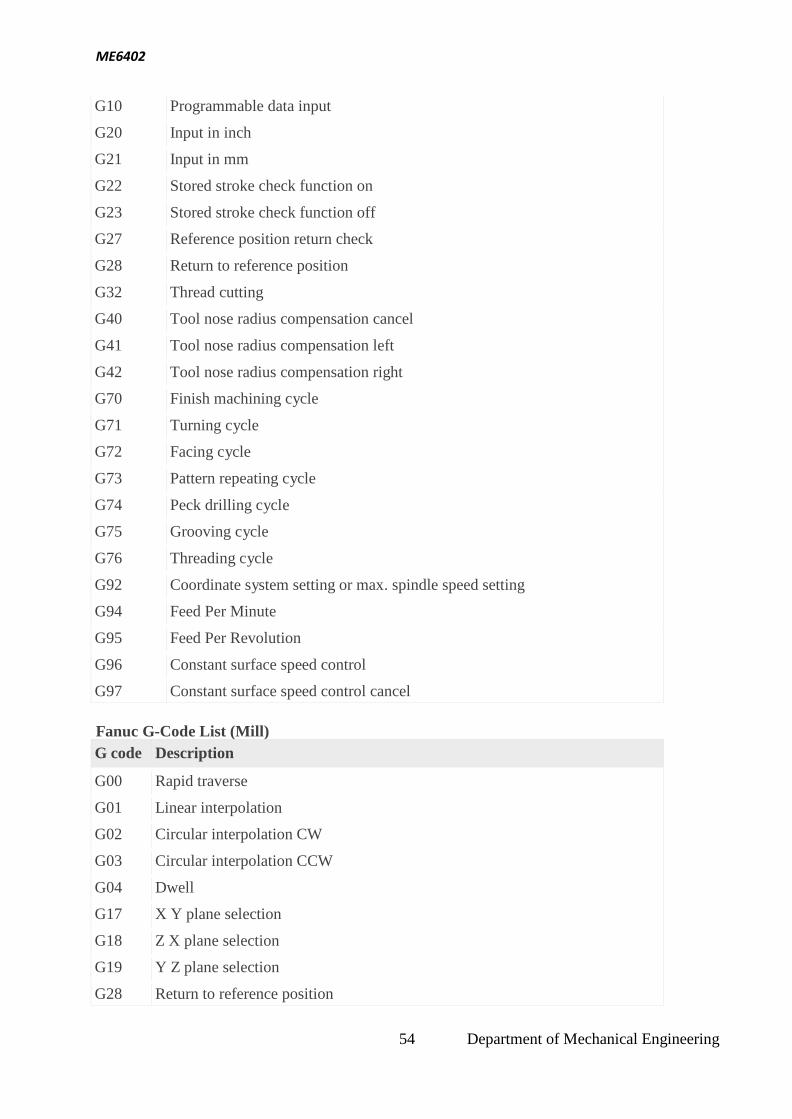
5.3 Programming Fundamentals CNC
Fanuc G-Code List (Lathe)
G code Description
G00 Rapid traverse
G01 Linear interpolation
G02 Circular interpolation CW
G03 Circular interpolation CCW
G04 Dwell
G09 Exact stop
53 Department of Mechanical Engineering
ME6402
G10 Programmable data input
G20 Input in inch
G21 Input in mm
G22 Stored stroke check function on
G23 Stored stroke check function off
G27 Reference position return check
G28 Return to reference position
G32 Thread cutting
G40 Tool nose radius compensation cancel
G41 Tool nose radius compensation left
G42 Tool nose radius compensation right
G70 Finish machining cycle
G71 Turning cycle
G72 Facing cycle
G73 Pattern repeating cycle
G74 Peck drilling cycle
G75 Grooving cycle
G76 Threading cycle
G92 Coordinate system setting or max. spindle speed setting
G94 Feed Per Minute
G95 Feed Per Revolution
G96 Constant surface speed control
G97 Constant surface speed control cancel
Fanuc G-Code List (Mill)
G code Description
G00 Rapid traverse
G01 Linear interpolation
G02 Circular interpolation CW
G03 Circular interpolation CCW
G04 Dwell
G17 X Y plane selection
G18 Z X plane selection
G19 Y Z plane selection
G28 Return to reference position
54 Department of Mechanical Engineering
ME6402
G30 2nd, 3rd and 4th reference position return
G40 Cutter compensation cancel
G41 Cutter compensation left
G42 Cutter compensation right
G43 Tool length compensation + direction
G44 Tool length compensation – direction
G49 Tool length compensation cancel
G53 Machine coordinate system selection
G54 Workpiece coordinate system 1 selection
G55 Workpiece coordinate system 2 selection
G56 Workpiece coordinate system 3 selection
G57 Workpiece coordinate system 4 selection
G58 Workpiece coordinate system 5 selection
G59 Workpiece coordinate system 6 selection
G68 Coordinate rotation
G69 Coordinate rotation cancel
G73 Peck drilling cycle
G74 Left-spiral cutting circle
G76 Fine boring cycle
G80 Canned cycle cancel
G81 Drilling cycle, spot boring cycle
G82 Drilling cycle or counter boring cycle
G83 Peck drilling cycle
G84 Tapping cycle
G85 Boring cycle
G86 Boring cycle
G87 Back boring cycle
G88 Boring cycle
G89 Boring cycle
G90 Absolute command
G91 Increment command
G92 Setting for work coordinate system or clamp at maximum spindle speed
G98 Return to initial point in canned cycle
G99 Return to R point in canned cycle
55 Department of Mechanical Engineering
ME6402
Fanuc M-Code List (Lathe)
M code Description
M00 Program stop
M01 Optional program stop
M02 End of program
M03 Spindle start forward CW
M04 Spindle start reverse CCW
M05 Spindle stop
M08 Coolant on
M09 Coolant off
M29 Rigid tap mode
M30 End of program reset
M40 Spindle gear at middle
M41 Low Gear Select
M42 High Gear Select
M68 Hydraulic chuck close
M69 Hydraulic chuck open
M78 Tailstock advancing
M79 Tailstock reversing
M94 Mirrorimage cancel
M95 Mirrorimage of X axis
M98 Subprogram call
M99 End of subprogram
Fanuc M-Code List (Mill)
M code Description
M00 Program stop
M01 Optional program stop
M02 End of program
M03 Spindle start forward CW
M04 Spindle start reverse CCW
M05 Spindle stop
M06 Tool change
M07 Coolant ON – Mist coolant/Coolant thru spindle
M08 Coolant ON – Flood coolant
56 Department of Mechanical Engineering
ME6402
M09 Coolant OFF
M19 Spindle orientation
M28 Return to origin
M29 Rigid tap
M30 End of program (Reset)
M41 Low gear select
M42 High gear select
M94 Cancel mirrorimage
M95 Mirrorimage of X axis
M96 Mirrorimage of Y axis
M98 Subprogram call
M99 End of subprogram
5.4 Manual Part Programming
Lathe
G02 G03 G Code Circular Interpolation
G02 G Code Clock wise Circular Interpolation.
G03 G Code Counter Clock wise Circular Interpolation.
There are multiple articles/cnc program examples about G code circular interpolation, here is
the list of few articles so that cnc machinists can easily navigate through different cnc
programming articles.
G02 G03 G Code Example CNC Programs (G code Arc Examples)
o CNC Circular Interpolation Tutorial G02 G03
o Fanuc CNC Lathe Programming Example
o CNC Programming Example G Code G02 Circular Interpolation Clockwise
o Fanuc G20 Measuring in Inches with CNC Program Example
o CNC Arc Programming Exercise
o CNC Programming for Beginners a CNC Programming Example
o CNC Lathe Programming Example
Here is a new CNC programming examples which shows the use of G02 G03 G code
circular interpolation.
G02 G03 G Code Example Program
57 Department of Mechanical Engineering
ME6402
G02 G03 G Code Circular Interpolation Example Program
N20 G50 S2000 T0300
G96 S200 M03 G42 G00 X35.0 Z5.0 T0303 M08
G01 Z-20.0 F0.2
G02 X67.0 Z-36.0 R16.0
G01 X68.0 :
G03 X100.0 Z-52.0 R16.0
G01 Z-82.0
G40 G00 X200.0 Z200.0 M09 T0300
M30
G Code G02 G03 I & K Example Program
G02 G03 G Code Circular Interpolation can be programmed in two ways,
G02 X... Z... R...
G02 X... Z... I... K...
The below is the same cnc program but this version uses I & K with G02 G03 G code.
N20 G50 S2000 T0300
G96 S200 M03 G42 G00 X35.0 Z5.0 T0303 M08
G01 Z-20.0 F0.2
G02 X67.0 Z-36.0 I16.0 K0
G01 X68.0 :
G03 X100.0 Z-52.0 I0 K-16.0
G01 Z-82.0
G40 G00 X200.0 Z200.0 M09 T0300
58 Department of Mechanical Engineering
ME6402
M30
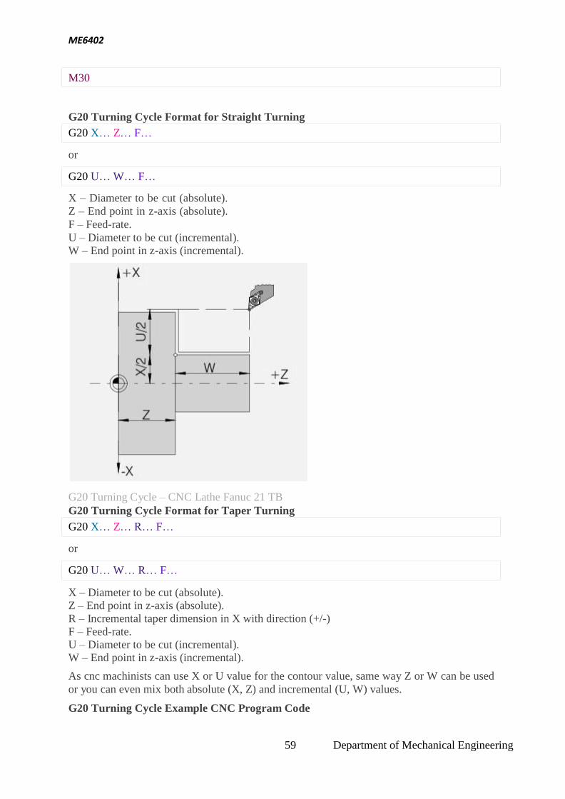
G20 Turning Cycle Format for Straight Turning
G20 X… Z… F…
or
G20 U… W… F…
X – Diameter to be cut (absolute).
Z – End point in z-axis (absolute).
F – Feed-rate.
U – Diameter to be cut (incremental).
W – End point in z-axis (incremental).
G20 Turning Cycle – CNC Lathe Fanuc 21 TB
G20 Turning Cycle Format for Taper Turning
G20 X… Z… R… F…
or
G20 U… W… R… F…
X – Diameter to be cut (absolute).
Z – End point in z-axis (absolute).
R – Incremental taper dimension in X with direction (+/-)
F – Feed-rate.
U – Diameter to be cut (incremental).
W – End point in z-axis (incremental).
As cnc machinists can use X or U value for the contour value, same way Z or W can be used
or you can even mix both absolute (X, Z) and incremental (U, W) values.
G20 Turning Cycle Example CNC Program Code
59 Department of Mechanical Engineering
ME6402
G96 S200 M03
G00 X56.0 Z2.0 G20 X51.0 W-20.0 F0.25
X46.0
X41.0
X36.0
X31.0
X30.0
G00 X100 Z100
M30
CNC Program Code Explanation
As you can see in the above cnc program code,
Tool is at X56 Z2 point,
First cut is made at X51 and tool travels W-20 in Z-axis.
Second cut is made at X46
Third cut is made at X41 …
Last cut is made at X30
G20 Turning Cycle Function
As if you study the above cnc program code you will notice that,
1 – with G20 both absolute (X51.0) and incremental (W-20.0) values are used to make cuts. 2 – If above code also shows a very powerful functionality of G20 turning cycle which is that
a cnc machinist can control depth-of-cut of every pass of G20 turning cycle which is
impossible to achieve with other Turning Canned Cycle like G71 Rough Turning Cycle.
So you will notice first five-cuts are of 5mm deep but the last one is just 1mm deep.
Cancellation of G20 Turning Cycle
G20 turning cycle is a modal G-code.
“Modal” G-code meaning that they stay in effect until they are cancelled or replaced by a
contradictory G code.
It means G20 turning cycle remains active until another motion command is given like G00,
G01 etc. As in above cnc program example G20 G code is cancelled with G00 G code.
Milling
Programming
G72.1 P... L... X... Y... R...
Parameters
Parameter Description
P Subprogram number
L Number of times the operation is repeated
X Center of rotation on the X axis
60 Department of Mechanical Engineering
ME6402
Y Center of rotation on Y axis
R
Angular displacement (a positive value indicates a counter clockwise angular displacement. Specify an incremental value.)
G-Code Data
Modal/Non-Modal G-Code Group
Non-Modal 00
Programming Notes
Notes 1. In the G72.1 block, addresses other than P, L, X, Y and R are ignored. 2. P, X, Y and R must always be specified.
3. If L is not specified, the figure is copied once.
4. The coordinate of the center of rotation is handled as an absolute value even if it is
specified in the incremental mode.
5. Specify an increment in the angular displacement at address R. The angular displacement
(degree) for the Nth figure is calculated as follows: Rx(N-1).
First block of the subprogram Always specify a move command in the first block of a subprogram that performs a rotational copy. If the first block contains only the program number such as O00001234; and
does not have a move command, movement may stop at the start point of the figure made by
the n-th (n = 1,2, 3, …) copying.
Example of an incorrect program
O00001234 ;
G00 G90 X100.0 Y200.0 ; ;
;
M99 ;
Example of a correct program
O00001000 G00 G90 X100.0 Y200.0 ;
;
;
M99 ;
Limitation Specifying two or more commands to copy a figure G72.1 cannot be specified more than once in a subprogram for making a rotational copy (If
this is attempted, alarmPS0900 will occur).
In a subprogram that specifies rotational copy, however, linear copy (G72.2) can
be specified. Similarly, in a subprogram that specifies linear copy, rotational copy can be
specified.
Commands that must not be specified
Within a program that performs a rotational copy, the following must not be specified:
Command for changing the selected plane (G17 to G19)
Command for specifying polar coordinates (G16)
Reference position return command(G28)
Axis switching
61 Department of Mechanical Engineering
ME6402
m
Coordinate system rotation (G68)
scaling (G51)
programmable mirror image (G51.1)
The command for rotational copying can be specified after a command for coordinate system
rotation, scaling, or program
Single
able mirror image is executed. block
Single-block stops are not performed in a block with G721.1 or G72.2.
G72.1 Programming Example
Main program
O1000 ;
N10 G90 G00 X80. Y100. ;
N20 Y50. ; (P2)
(P1)
N30 G01 G17 G42 X43.301 Y25. D01 F100 ;(P3)
N40 G72.1 P1100 L3 X0 Y0 R120. ;
N50 G90 G40 G01 X80. Y50. ; (P2)
N60 G00 X80. Y100. ;
N70 M30 ;
(P1)
62 Department of Mechanical Engineering
ME6402
Sub program
O1100 G91 G03 X-18.301 Y18.301 R50. ; (P4)
N100 G01 X-5. Y50. ; (P5)
N200 G03 X-40. I-20. ; (P6)
N300 G01 X-5. Y-50. ; (P7)
N400 G03 X-18.301 Y-18.301 R50. ; (P8)
N500 M99 ;
5.5 Micromachining
Superfinishing, a metalworking process for producing very fine surface finishes
Various micro electro mechanical systems
Bulk micromachining
Surface micromachining
High-aspect-ratio microstructure technologies
Bulk micromachining is a process used to produce micro machinery or micro electro
mechanical systems (MEMS).
Unlike surface micromachining, which uses a succession of thin film deposition and
selective etching, bulk micromachining defines structures by selectively etching inside a
substrate. Whereas surface micromachining creates structures on top of a substrate, bulk
micromachining produces structures inside a substrate.
Usually, silicon wafers are used as substrates for bulk micromachining, as they can
be anisotropically wet etched, forming highly regular structures. Wet etching typically
uses alkaline liquid solvents, such as potassium hydroxide (KOH) or tetramethylammonium
hydroxide (TMAH) to dissolve silicon which has been left exposed by the photolithography
masking step. These alkali solvents dissolve the silicon in a highly anisotropic way, with
some crystallographic orientations dissolving up to 1000 times faster than others. Such an
approach is often used with very specific crystallographic orientations in the raw silicon to
produce V-shaped grooves. The surface of these grooves can be atomically smooth if the
etch is carried out correctly, and the dimensions and angles can be precisely defined.
Bulk micromachining starts with a silicon wafer or other substrates which is selectively
etched, using photolithography to transfer a pattern from a mask to the surface. Like surface
micromachining, bulk micromachining can be performed with wet or dry etches, although
the most common etch in silicon is the anisotropic wet etch. This etch takes advantage of the
fact that silicon has a crystal structure, which means its atoms are all arranged periodically in
lines and planes. Certain planes have weaker bonds and are more susceptible to etching. The
etch results in pits that have angled walls, with the angle being a function of the crystal
orientation of the substrate. This type of etching is inexpensive and is generally used in early,
low-budget research.
Unlike Bulk micromachining, where a silicon substrate (wafer) is selectively etched to
produce structures, surface micromachining builds microstructures by deposition and etching
of different structural layers on top of the substrate. Generally polysilicon is commonly used
as one of the layers and silicon dioxide is used as a sacrificial layer which is removed or
etched out to create the necessary void in the thickness direction. Added layers are generally
63 Department of Mechanical Engineering
ME6402
very thin with their size varying from 2-5 Micro metres. The main advantage of this
machining process is the possibility of realizing monolithic microsystems in which the
electronic and the mechanical components(functions) are built in on the same substrate. The
surface micromachined components are smaller compared to their counterparts, the bulk
micromachined ones.
As the structures are built on top of the substrate and not inside it, the substrate's properties
are not as important as in bulk micromachining, and the expensive silicon wafers can be
replaced by cheaper substrates, such as glass or plastic. The size of the substrates can also be
much larger than a silicon wafer, and surface micromachining is used to produce TFTs on
large area glass substrates for flat panel displays. This technology can also be used for the
manufacture of thin film solar cells, which can be deposited on glass, but also
on PET substrates or other non-rigid materials.
HARMST is an acronym for High Aspect Ratio Microstructure Technology that describes
fabrication technologies, used to create high-aspect-ratio microstructures with heights
between tens of micrometers up to a centimeter and aspect ratios greater than 10:1. Examples
include the LIGA fabrication process, advanced silicon etch, and deep reactive ion etching.
5.6 Water Machining
A water jet cutter, also known as a waterjet or waterjet, is an industrial tool capable of
cutting a wide variety of materials using a very high-pressure jet of water, or a mixture of
water and an abrasive substance. The term abrasive jet refers specifically to the use of a
mixture of water and abrasive to cut hard materials such as metal or granite, while the
terms pure waterjet and water-only cutting refer to waterjet cutting without the use of added
abrasives, often used for softer materials such as wood or rubber. Waterjet cutting is often
used during fabrication of machine parts. It is the preferred method when the materials being
cut are sensitive to the high temperatures generated by other methods. Waterjet cutting is
used in various industries, including mining andaerospace, for cutting, shaping, and reaming.
Water jet CNC cutting Machine While using high-pressure water for erosion dates back as far as the mid-1800s
with hydraulic mining, it was not until the 1930s that narrow jets of water started to appear
as an industrial cutting device. In 1933, the Paper Patents Company in Wisconsin developed
a paper metering, cutting, and reeling machine that used a diagonally moving waterjet nozzle
to cut a horizontally moving sheet of continuous paper. These early applications were at a
low pressure and restricted to soft materials like paper.
64 Department of Mechanical Engineering
ME6402
Waterjet technology evolved in the post-war era as researchers around the world searched for
new methods of efficient cutting systems. In 1956, Carl Johnson of Durox International in
Luxembourg developed a method for cutting plastic shapes using a thin stream high-pressure
waterjet, but those materials, like paper, were soft materials.[3]
In 1958, Billie Schwacha of
North American Aviation developed a system using ultra-high-pressure liquid to cut hard
materials.[4]
This system used a 100,000 psi (690 MPa) pump to deliver ahypersonic liquid
jet that could cut high strength alloys such as PH15-7-MO stainless steel. Used as a
honeycomb laminate on the Mach 3 North American XB-70 Valkyrie, this cutting method
resulted in delaminating at high speed, requiring changes to the manufacturing process.
While not effective for the XB-70 project, the concept was valid and further research
continued to evolve waterjet cutting. In 1962, Philip Rice of Union Carbideexplored using a
pulsing waterjet at up to 50,000 psi (345 MPa) to cut metals, stone, and other
materials. Research by S.J. Leach and G.L. Walker in the mid-1960s expanded on traditional
coal waterjet cutting to determine ideal nozzle shape for high-pressure waterjet cutting of
stone, and Norman Franz in the late 1960s focused on waterjet cutting of soft materials by
dissolving long chain polymers in the water to improve the cohesiveness of the jet stream. In
the early 1970s, the desire to improve the durability of the waterjet nozzle led Ray
Chadwick, Michael Kurko, and Joseph Corriveau of the Bendix Corporation to come up with
the idea of using corundum crystal to form a waterjet orifice, while Norman Franz expanded
on this and created a waterjet nozzle with an orifice as small as 0.002 inches (0.05 mm) that
operated at pressures up to 70,000 psi (483 MPa). John Olsen, along with George Hurlburt
and Louis Kapcsandy at Flow Research (later Flow Industries), further improved the
commercial potential of the waterjet by showing that treating the water beforehand could
increase the operational life of the nozzle.
Abrasive waterjet
The Evolution of the Abrasive Waterjet Nozzle
While cutting with water is possible for soft materials, the addition of an abrasive turned the
waterjet into a modern machining tool for all materials. This began in 1935 when the idea of
adding an abrasive to the water stream was developed by Elmo Smith for the liquid abrasive
blasting. Smith’s design was further refined by Leslie Tirrell of the Hydroblast Corporation
in 1937, resulting in a nozzle design that created a mix of high-pressure water and abrasive
for the purpose of wet blasting. Producing a commercially viable abrasive waterjet nozzle for
precision cutting came next by Dr. Mohamed Hashish who invented and led an engineering
research team at Flow Industries to develop the modern abrasive waterjet cutting
65 Department of Mechanical Engineering
ME6402
technology. Dr. Hashish, who also coined the new term "Abrasive Waterjet" AWJ, and his
team continued to develop and improve the AWJ technology and its hardware for many
applications which is now in over 50 industries worldwide. A most critical development was
creating a durable mixing tube that could withstand the power of the high-pressure AWJ, and
it was Boride Products (now Kennametal) development of their ROCTEC line of
ceramic tungsten carbide composite tubes that significantly increased the operational life of
the AWJ nozzle. Current work on AWJ nozzles is on micro abrasive waterjet so cutting with
jets smaller than 0.015 inch in diameter can be commercialized.
Applications
Because the nature of the cutting stream can be easily modified the water jet can be used in
nearly every industry; there are many different materials that the water jet can cut. Some of
them have unique characteristics that require special attention when cutting.
Materials commonly cut with a water jet include rubber, foam, plastics, leather, composites,
stone, tile, metals, food, paper and much more. Materials that cannot be cut with a water jet
are tempered glass, diamonds and certain ceramics. Water is capable of cutting materials
over eighteen inches (45 cm) thick.
66 Department of Mechanical Engineering
ME6402
6. QUESTION BANK
UNIT-I
THEORY OF METAL CUTTING
PART-A
1. What is tool signature?
2. What is side rake angle? And mention its effects?
3. What is clearance angle? And mention its types?
4. Explain the nose radius.
5. Sketch the orthogonal cutting.
6. What is shear plane?
7. What is cutting force?
8. What is chip and mention its different types?
9. Define machinability of metal.
10. Write Taylor’s tool life equation
PART-B
1. Explain orthogonal cutting and oblique cutting with its neat sketches and compare.
2. What is the tool life equation and state the factor affecting the tool life.
3. What is machinability? And explain.
4. Explain the various tool materials.
5. Write short notes on surface finish.
6. What are the different types of cutting fluids used in machining process?
7. Write short notes tool wear. 67 Department of Mechanical Engineering
ME6402
UNIT-II
CENTRE LATHE & SPECIAL PURPOSE LATHES
PART-A
1. What is swing diameter?
2. Write the specification of a typical lathe.
3. Write down the names of any four lathe accessories.
4. What is the application of air operated chuck?
5. Define the term “Concity”.
6. Write down the formula for calculating taper turning angle by compound rest method.
7. Define the term „Thread catching‟.
8. Define automatic machine.
9. State the principal of multi spindle automats.
10. Classify multi spindle automats.
PART-B
1. Sketch a center lathe and mention various parts. .
2. List various type of feed mechanisms and explain briefly about tumbler gear reversing
mechanism with a sketch.
3. Explain taper turning operation i n a lathe by a taper turning attachment .Discuss its
advantages.
4. Explain the following methods of taper turning i n a lathe.
5. (i) By swiveling the compound rest.
(ii) By a taper turning attachment.
6. Explain the Working principle of capstan and turret lathes.
7. Explain the tooling layout for the production of a Hexagonal bolt in a capstan lathe.
8. Discuss the tooling layout for the production of a Hexagonal nut in Turret lathe.
9. Classify transfer machines. Sketch and explain the working of Swiss type automatic screw
machine. What are the advantages of automatic machines?
10. Describe a typical single spindle automatic chucking machine.
11. Describe a typical single spindle automatic bar machine
12. Differentiate between parallel action and progressive action multi -spindle automatics.
68 Department of Mechanical Engineering
ME6402
UNIT-III
OTHER MACHINE TOOLS PART-A
1. Write down any four operations performed by a shaper.
2. Define feed and depth of cut.
3. What is the function of clapper block in a planner?
4. What are the differences between up milling and down milling?
5. Define “Face milling “.
6. Write down the rule for gear ratio in differential indexing.
7. How do you specify radial drilling machine.
8. Write down any four operations performed by a drilling machine.
9. What is meant by “Sensitive hand feed”?
10. Calculate the tap drill size to cut an internal thread for bolt of outside diameter 10mm,
pitch 1.5mm and depth of the thread 0.61 pitch.
PART-B
1. With a simple sketch, explain the working of the crank and slotted link quick return
motion mechanism used in shaper.
2. Write down any four differences between shaper and planer. .
3. Explain the Working principle of planer with a neat sketch.
4. How do you specify a planer?
5. Describe the working mechanism of a universal dividing head, with neat diagram.
6. With a neat sketch, indicate the various parts of an arbor assembly.
7. With a simple sketch, explain the principal parts and angles of a plain milling cutter
.Explain them.
8. Explain the twist drill nomenclature and define various elements of twist drill.
9. With a simple sketch, explain the working of a vertical boring machine.
10. Explain the counter boring and counter ringing operation.
11. Explain the Working principle of a Jig boring machine with a neat sketch.
69 Department of Mechanical Engineering
ME6402
UNIT-IV
ABRASIVE PROCESSES & GEAR CUTTING PART-A
1. What is the process of self sharpening of the grinding wheel?
2. What are the four moments in a cylindrical centre type grinding.
3. What is meant by centerless grinding?
4. Define the terms abrasive grains.
5. What is meant by grit or grains size.
6. Define the term grade used i n grinding wheel.
7. What is open and dense structure?
8. What is meant by dressing and truing?
9. What is meant by honing?
10. What is super finishing?
PART-B
1. What are the various methods of centerless grinding and each briefly?
2. Explain the external cylindrical grinding process and surface grinding process.
3. Explain the vitrified and resinoid bonding process.
4. E xplain the operations of horizontal broaching machine with neat sketch.
5. Explain the gear cutting by a formed tool.
6. Differentiate between gear forming and generating.
7. Explain the principle of operation of gearing hobbing operation what are the advantages of
gear hobbing.
8. Give advantages and limitations of gear hobbing.
70 Department of Mechanical Engineering
ME6402
UNIT-V
CNC MACHINE TOOLS & PART PROGRAMMING
PART-A
1. State the advantages of NC machines.
2. Draw the simple configuration of CNC machine
3. Mention the main different between C NC and DNC
4. What is the function of servo valve?
5. Define absolute and incremental programming.
6. What are the important steps to be followed while preparing part programming?
7. What is meant by MACRO?
8. Define subroutine
9. What do mean by canned cycle
10. What is meant by APT programme?
PART-B
1. List the various drive systems explain the principle of any two rive system.
2. Explain open loop and closed loop system
3. What is machining centers explain in detail
4. Explain various types of CMM
5. Explain the part programming procedure with a good example
6. List and explain G and M code for turning milling operations
7. Explain NC axis conventions.
71 Department of Mechanical Engineering
ME6402
2-MARKS - V - UNITS UNIT I – THEORY OF METAL CUTTING
1. Define Metal Cutting .
Metal cutting or machining is the process of by removing unwanted material from a
block of metal in the form of chips. 2. What are the important characteristics of materials used for cutting tools?
High red hardness High wear resistance
High toughness
High thermal conductivity.
3. How do you define tool life?
Low frictional co- efficient
The time period between two consecutive resharpening, with which the cuts the material effectively is called as tool life.
4. What is tool signature?
The various angles of tools are mentioned in a numerical number in particular order.
That is known as tool signature.
5. What is the effect of back rack angle and mention the types? Back rake angle of tool is increases the strength of cutting tool and cutting action. It
can be classified in to two types.
1. Negative Rake angle.
2. Positive rake angle.
6. Explain the nose radius?
Joining of side and end cutting edges by means of small radius in order to increase
the tool life and better surface finish on the work piece.
7. What are all conditions for using positive rake angle?
1. To machine the work hardened materials.
2. To machine low strength ferrous and non-ferrous
metals.
3. To machine long shaft of small diameters.
72 Department of Mechanical Engineering
ME6402
4. To machine the metal blow recommended cutting speeds.
5. Using small machine tools with low horsepower.
8. Define the orthogonal and oblique cutting.
Orthogonal cutting: The cutting edge of tool is perpendicular to the work piece axis. Oblique cutting: The cutting edge is inclined at an acute angle with normal to the cutting velocity vector is called oblique cutting process.
9. What are the favorable factors for discontinuous chip formation?
Maching of brittle materials. Small rake angle
Higher depth of cut Low cutting speeds
Excess cutting fluid.
Cutting ductile materials with low speed and small rake angle of the tool.
10. What are the favorable factors for continuous chip formation?
Small rake angle Low cutting speed
Strong adhesion between chip and tool face. Coarse feed
Insufficient cutting fluid. Large uncut thickness.
11. Define machineability of metal.
Machine ability is defined as the ease with which a material can be satisfactorily
machined. Life of the tool before tool failure or resharpening.
12. What is shear plane?
The material of work piece is stressed beyond its yield point under the compressive force.
This causes the material to deform plastically and shear off. The plastic floe takes place in a
localized region is called shear plane.
13. What is chip and mention its different types?
The sheared material begins to along the cutting tool face in the form of small pieces is
called chip. The chips are mainly classified into three types.
a. Continuous chip.
b. Discontinuous chip.
c. Continuous chip with built up edge.
73 Department of Mechanical Engineering
ME6402
14. Write the factors affecting the tool life or Write the Taylor’s tool life equation.
Taylor’s equation VT n = C
i. Cutting speed
ii. Feed and Depth of cut.
iii.Tool Geometry
iv. Tool material
v. Type of Cutting Fluid
vi. Work material
vii. Rigidity of the Machine tool.
15. Define “Side relief” and “End relief” angle.
Side relief angle: It is the angle between the portion of the side flank immediately below the
side cutting edge and a line perpendicular to the base of the tool, and measured at right angle
to the side flank.
End relief angle: It is the angle between the portion of the end flank immediately below the
end cutting edge and a line perpendicular to the base of the tool, and measured at right angle
to the angle.
16. What are the importance of Nose Radius?
Nose radius is favorable to long tool life and good surface finish. A sharp point on the
end of a tool is highly stressed, Short lived and leaves a groove in the path of cut. There is an
improvement in surface finish and permissible cutting speed as nose radius is increased from
zero value.
17. What are the differences between orthogonal cutting and oblique cutting?
orthogonal cutting oblique cutting
Cutting edge of the tool is perpendicular to the direction of tool travel
Cutting edge of the tool is inclined to the direction of tool travel
The direction of chip flow is perpendicular to the cutting edge
The direction of chip flow is angled to the cutting edge
The chip coils in a tight flat spiral The chip flows sideways in a long.
Produces sharp corners. Produces chamfer at the end of cut.
74 Department of Mechanical Engineering
ME6402
UNIT II – TURNING MACHINES
1. What is a Lathe?
Lathe is a machine tool which removes the metal from a piece of work to the
required shape and size.
2. What are the uses of headstock?
Headstock carries a hollow spindle with nose to hold the work piece. To Mount the driving and speed changing mechanisms.
3. What is an apron?
The integral part of several gears, levers and clutches mounted with the saddle for
moving the carriage along with lead screw while thread cutting.
4. What are the advantages semi-automatic lathes? Production time is minimized Accuracy will be high. Production rate is increased.