Page 1
Louisiana State UniversityLSU Digital Commons
LSU Master's Theses Graduate School
2007
Manufacturing, Testing and Modeling of AdvancedFilament Wound Grid Stiffened CompositeCylindersRavi Chaitanya VelamarthyLouisiana State University and Agricultural and Mechanical College, [email protected]
Follow this and additional works at: https://digitalcommons.lsu.edu/gradschool_theses
Part of the Mechanical Engineering Commons
This Thesis is brought to you for free and open access by the Graduate School at LSU Digital Commons. It has been accepted for inclusion in LSUMaster's Theses by an authorized graduate school editor of LSU Digital Commons. For more information, please contact [email protected] .
Recommended CitationVelamarthy, Ravi Chaitanya, "Manufacturing, Testing and Modeling of Advanced Filament Wound Grid Stiffened CompositeCylinders" (2007). LSU Master's Theses. 4149.https://digitalcommons.lsu.edu/gradschool_theses/4149
Page 2
MANUFACTURING, TESTING AND MODELING OF
ADVANCED FILAMENT WOUND GRID STIFFENED
COMPOSITE CYLINDERS
A Thesis
Submitted to the Graduate Faculty of the
Louisiana State University and
Agricultural and Mechanical College
in partial fulfillment of the
requirement for the degree of
Master of Science in Mechanical Engineering
in
The Department of Mechanical Engineering
by
Ravi Chaitanya Velamarthy
Bachelor of Technology, Jawaharlal Nehru Technological University, India, 2004
December 2007
Page 3
ii
Acknowledgements
I would like to express my sincere gratitude to Dr. Guoqiang Li, my major professor, for giving
me an opportunity to work on this research and for his guidance and support over the past two
years. Without his help this thesis would not have been possible. I would like to thank Dr. Su-
Seng Pang and Dr. Eyassu Woldesenbet for agreeing to be part of my thesis defense committee. I
would also like to thank Mr. Randy Young and all the personnel at the Louisiana Transportation
Research Centre (LTRC) for their time and help. Finally I would like to thank my family, all my
friends and well-wishers.
This study is partially sponsored by a grant from the Federal Highway
Administration/Innovative Bridge Research and Construction program and the Louisiana
Transportation Research Center.
Page 4
iii
Table of Contents
ACKNOWLEDGEMENTS …………………………………………………….……. ii
LIST OF TABLES……………………………………………………………………. v
LIST OF FIGURES…………………………………………………………………… vi
ABSTRACT ………………………………………………………………………..… ix
CHAPTER
1 INTRODUCTION ……………………………………………………..….…. 1
2 LITERATURE REVIEW …………………………………………………..… 6
3 MANUFACTURING AND CHARACTERIZATION………………..…..….. 10
3.1 Raw Material Properties ………………………………………..…..… 10
3.2 Filament Winding Technique ………………………………….….….. 11
3.3 Fabrication…………….………………………………….………..….. 12
3.4 Mold Removal System …………………………………….…………. 15
3.5 Concrete………………………………………………………………. 19
3.6 Burn-Out Test ……………………………………………….….….…. 20
3.7 Mechanical Properties of the AGS Cylinders……………………....…. 22
4 TESTING AND ANALYSIS ……………………………………………........ 25
4.1 Instrumentation ……………………………………………………..... 26
4.2 Results and Analysis ……………………………………………….… 28
4.2.1 Control Samples …………………………………………….... 28
4.2.2 Concrete Filled Grid Stiffened Cylinders ………………….… 34
4.3 Effect of Design Variables ………………………………………….... 39
4.3.1 Variation of Skin Thickness………………………………….. 39
4.3.2 Variation of Rib Thickness…………………………………… 40
4.3.3 Variation of Bay Area………………………………..……….. 41
5 FINITE ELEMENT MODELING …………………………………………… 42
5.1 Element Types ……………………………………………………….. 44
5.2 Drucker-Prager Criteria………………………………………………. 46
5.3 Boundary Conditions and Loading …………………………………… 48
5.4 Convergence Check …………………………………………………... 49
5.5 Nonlinear Analysis ………………………………………………….... 50
5.6 Finite Element Solution ………………………………………………. 51
5.6.1 Specimen Without Skin ………………………………………. 51
Page 5
iv
5.6.2 Specimen With Skin ………………………………….….…… 52
5.6.3 FRP Grid Tube Confined Concrete Specimen ……………….. 53
6 PARAMETRIC STUDY …………………………………………….……….. 59
6.1 Grid Cylinders Without Concrete …………………………….……… 59
6.1.1 Effect of Skin Thickness ………………………………….….. 59
6.1.2 Effect of Material Properties …………………………….…… 60
6.1.3 Effect of Rib Thickness …………………………….……….... 61
6.1.4 Effect of Bay Area ……………………………………………. 62
6.2 FRP Grid Tube Confined Concrete Cylinders ……………………....... 64
6.2.1 Effect of Skin Thickness ……………………………….……... 65
6.2.2 Effect of Material Properties …………………………………. 66
6.2.3 Effect of Rib Thickness ………………………………………. 66
6.2.4 Effect of Bay Area ……………………………………………. 67
7 CONCLUSIONS AND RECOMMENDATIONS....……….………………… 70
7.1 Future Work…………………………………………………………… 71
REFERENCES ……………………………………………………………………….. 72
VITA ………………………………………………………………………………….. 76
Page 6
v
List of Tables
1 Physical/Mechanical properties of the raw materials used …………….......... 10
2 Physical parameters of the samples ……………………………………..…… 18
3 Percentage content of the materials in the concrete ………..……………..…. 19
4 Properties of the concrete……………………………………………….……. 20
5 Volume fraction of the fibers ……..………………………………………..… 22
6 Material properties of the composite AGS cylinder ………………...…...…… 23
7 Material properties of the nodes ………………………………………..…….. 24
8 Material properties of the skin ……………………………………………....... 24
9 Load carrying capacities of the composite structures………………………… 30
10 Peak loads carried by grid structures with skin wound at 0o, 35
o and 75
o…… 34
11 Maximum load carried by the samples……………………………………….. 35
12 Schematic of the load carrying capacity of the composite elements ……........ 36
13 Load carrying capacity for cylinders with different skin thicknesses …....….. 40
14 Load carrying capacity for cylinders with different rib thicknesses………….. 40
15 Load carrying capacity for cylinders with different bay areas…………….….. 41
16 Drucker-Prager parameters………………………………………………..….. 48
Page 7
vi
List of Figures
1 Schematic of the filament winding process...………………..……….……… 11
2 “Little Hornet” Two-axis filament winding machine…...…………………… 12
3 Collapsible mandrel with holes…………………………………….………... 13
4 Grid structure on the collapsible mandrel with pin…………………….……. 14
5 Grid structure with the skin on the filament winding machine mandrel…..…. 15
6 Jumpstart system and utility winch mounted on the wooden platform….…... 16
7 Mold removal system…………………………………………….….……….. 16
8 Collapsible mandrel…………………………………….……………………. 17
9 Collapsible mandrel and grid structure………………………………….…… 17
10 AGS cylinder without the skin ………………………………………………. 18
11 AGS cylinder with the skin…………………………………………………... 18
12 FORNEY compression testing machine …………………………..……........ 25
13 YOKOGAWA DC100 data acquisition system …………………………....... 26
14 Mounted strain gages........................................................................................ 27
15 Strain gages pasted on the skin of the grid stiffened cylinder……………….. 27
16 Specimens under compression testing ………………………………….…… 28
17 Load-displacement graph of the grid cylinders ………..….………….….….. 29
18 Rib under compression …………………………………………………….... 29
19 Localized rib buckling and stiffener crippling of the grid structure …….….. 31
20 Failure of the skin and the ribs of the grid cylinder wound with skin …….… 33
21 Variation of the stress in the grid cylinder with the skin angle ……….….…. 33
22 Stress-strain graph for a grid with skin and a confined concrete cylinder….... 35
Page 8
vii
23 Finite element model of the grid structure without the skin ……..………..…. 42
24 Finite element model of the grid structure with the skin …….…………..…... 43
25 SOLID191 geometry and coordinate system …………………………..……. 44
26 SHELL46 geometry and coordinate system …………………………………. 45
27 SOLID65 geometry and coordinate system ………………………………….. 45
28 Stress-strain relationship for concrete……………………………………….... 51
29 Stresses in the grid structure without skin ………………………….……........ 52
30 Stresses in the grid structure with skin ……………………………………….. 53
31 Crushing and cracking of the finite element model of the concrete ………..... 54
32 Stresses developed in a FRP grid tube encased concrete cylinder ……….….. 55
33 Stresses developed in the concrete………………………………..……........... 55
34 Stresses developed in the skin …………………………………….…….......... 56
35 Stresses developed in the grid …………………………………….….……...... 56
36 Experimental and FEA stress-strain curves……………….……….…….……. 57
37 Experimental and FEA stress-strain curves for a different confined cylinder... 58
38 Effect of skin thickness on the hoop stress …………………………………… 60
39 Effect of material properties on the hoop stress ………………………............ 61
40 Effect of rib thickness on the hoop stress …………………………….………. 62
41 Effect of bay area on the hoop stress …………………………………………. 63
42 Effect of zero bay area on the hoop stress …………….……………..……...... 64
43 Effect of skin thickness on the hoop stress ………………………………….... 65
44 Effect of material properties on the hoop stress …... …………………..……. 66
45 Effect of rib thickness on the hoop stress ……………………………….……. 67
Page 9
viii
46 Effect of bay area on the hoop stress ………………………………….….... 68
47 Effect of a zero bay area grid cylinder on the hoop stress…………………. 69
Page 10
ix
Abstract
Advanced Grid Stiffened (AGS) structures are a kind of FRP composites that are being
extensively used in many engineering fields because of their inherent advantages. Hence it is of
utmost importance to understand the basic mechanism of these structures in order to develop
better models and to find ways to improve their efficiency. This thesis discusses the
manufacturing technology used viz. the filament winding technique to fabricate grid stiffened
composite cylinders. A step by step procedure of the fabrication process of grid cylinders is
explained. The confinement effectiveness of the AGS cylinders is evaluated by filling them with
concrete and subjecting the specimens to uniaxial compression tests. The results from the
experiments show that the grid stiffened cylinders have more load carrying capacity than the
normal FRP pipes. The stiffeners in the grid structures increase the structural capacity and also
prevent the global buckling of the grid cylinders. It is seen that the skin wound at a certain angle
provides satisfactory lateral confinement to the grid structure and the desired composite action is
achieved between the grid structure and the skin. The AGS structures are able to effectively
confine the concrete, thereby increasing their strength multi-fold.
To validate the results obtained from the experiments a 3-D finite element model of the
grid stiffened cylinder was developed using ANSYS. The nonlinear behavior of the materials
used in the experiments was incorporated into the FEA model by considering the appropriate
stress-strain relationships. The behavior of the confined concrete composite cylinder was
modeled using a non-associative Drucker-Prager plasticity criterion. The validated FEA model
was used to perform a parametric analysis. Several design parameters were identified that seem
to have an effect on the load carrying capacity of the grid structures. These parameters were then
varied using the FEA model to evaluate the structural behavior of the cylinders and the results
Page 11
x
were analyzed to efficiently design high strength grid stiffened composite cylinders. Finally a
discussion of the results from both the experiments and the FEA model are presented and general
conclusions are drawn.
Page 12
1
Chapter 1
Introduction
Over the years, composite materials have been gaining wide acceptance into many engineering
fields particularly aerospace and civil industries. Their increasing prominence relates to the
ability of these materials to be tailored to suit any particular functional requirement [1]. Modern
composites have strengths and stiffnesses far above those of traditional materials [2]. Composite
materials can be defined as those that contain two or more constituent materials on a macro
scale, each with different properties while still remaining distinct within the finished structure.
This combination results in a new material which has several unique properties which cannot be
achieved with either of the constituents acting alone. One of the main advantages of the
composite materials is their potential for high ratio of strength-to-weight and stiffness-to-weight.
Other advantages include light weight, corrosion resistance, high specific strength, high specific
stiffness, ease of fabrication, etc. Aircraft fuselage and launch vehicle fuel tanks are some of the
many applications of these structures in aerospace and aircraft industries [3]. Their uses in civil
infrastructure applications include repair, rehabilitation, reinforcement, and rebuilding of
engineering structures like buildings, bridges, pipelines, etc.
Fibrous composites are a type of composite materials which contain fibers impregnated
by a binder material called matrix. Fiber Reinforced Polymers (FRP) are light-weight, high
strength composite materials made of fibers (glass, carbon, silicon carbide, etc) embedded in a
polymeric matrix (epoxy, vinyl ester, etc.). The fibers are the principal load carrying members
with matrix serving in binding the fibers together and to transfer loads to the fibers. Matrix also
Page 13
2
protects the fibers from damage due to external environment like corrosion, abrasion,
temperature, humidity, etc. The fibers can be arranged in any random direction, but it is also
possible for them to be oriented preferentially in the direction where high stresses are expected.
For this very reason FRP composites are said to be anisotropic in nature as opposed to many of
the traditional materials like aluminum which are isotropic, i.e. they have properties which are
apparent in the direction of applied load unlike isotropic materials in which properties are
uniform in all directions independent of applied load. This control of anisotropy helps in
designing composite structures to suit any specific application.
Advanced Grid Stiffened (AGS) structures can be defined as those that have a particular
stiffening arrangement either on the inner or outer or both sides of the structure. The stiffening
structure can be a simple orthogrid type arrangement or a more complex pattern. The type of
stiffening configuration depends on the type of application, the loading conditions, costs and
other factors [4]. Depending on the configuration, different failure modes are observed in the
stiffened structures. Generally AGS structures are characterized by a lattice of rigid,
interconnected ribs, which proves to be an inherently strong and resilient arrangement for
composite materials [5]. The grid structures derive their strength from the unidirectionally-
reinforced continuous-fiber ribs. The lattice arrangement of the ribs helps in eliminating material
mismatch associated with laminated structures, as a result of which the crack propagation is
confined to a unit cell thereby preventing the failure of the entire structure. Due to this reason,
grid structures are being extensively used in designing payload fairing in launch vehicles and
offshore oil drilling platforms. They are also used in bridge decks, girders, piers/piles because
composite grid structures when combined with materials like concrete provide strength and
ductility to concrete in addition to solving the problem of corrosion which is inherent with steel
Page 14
3
reinforcements [6]. AGS cylinders help in reducing the buckling phenomenon which is common
in columns subjected to compression. This is the reason why grid cylinders are used to confine
concrete columns and piers because grid structures provide effective confinement to the concrete
thereby increasing its ductility and preventing the ribs from buckling. Analysis of grid-stiffened
structures include complex interactions between the skin and the stiffeners which must be
understood to design structures that better resist damage due to different types of loading .
Several types of manufacturing technologies exists, like the filament winding technology,
which helps in considerably reducing the difficulties in fabricating structures like grid-stiffened
cylinders while reducing the fabricating costs. These new automatic fiber placement techniques
offer a good control over quality of the part being produced with minimum or no human
intervention. Parts with complex shapes can also be fabricated easily and at high speed. Other
manufacturing techniques include concepts like tooling methods which are based on precise
understanding of tooling behavior to fabricate cost-effective structures.
The finite element method (FEM) is a numerical procedure that is used to solve a large
scale of engineering problems involving stress analysis, heat transfer, electromagnetism, fluid
flow, etc [7]. The analysis of complex structures and other systems becomes quite easy when
using the finite element method. The basic idea behind the FEM is to discretize the domain of
interest into several small points and subdomains called nodes and elements. Once the
discretization of the domain is done it creates a system of linear or nonlinear algebraic equations
that are solved to represent the solution of each element. The solutions for these individual
elements are then connected to represent the complete solution of the model.
There are three basic steps involved in any finite element analysis. Brief description of each of
these steps is given below.
Page 15
4
1. Preprocessing Phase
This involves creating and discretizing the area of interest into finite elements to which
boundary and loading conditions are applied.
2. Solution Phase
In this phase a set of linear equations are solved to obtain nodal results.
3. Postprocessing Phase
Finally important information such as principle stresses, heat fluxes, etc. are obtained.
Several finite element softwares are available commercially viz. ANSYS, ABAQUS,
COSMOS/M, etc. which encompasses simulation, validation and optimization of systems and
products. Parametric study is another important application of finite element analysis wherein
components or systems can be modeled by varying different parameters to evaluate their affect
on the system. This helps in reducing the number of experiments to be performed, thereby
lowering the manufacturing costs and time.
This thesis presents the manufacturing technology used to fabricate the circular grid
stiffened cylinders. The fabrication process and experimental setup are explained in detail. A
number of cylinders were fabricated by varying several parameters like bay area, thickness of the
ribs, skin thickness and skin orientation angle. Analysis of the load carrying capacity and failure
modes of these different cylinders subjected to compression was also conducted. The
confinement effectiveness of the grid cylinders when they are filled with concrete was evaluated.
Finally a finite element model of the AGS cylinder was developed using ANSYS finite element
software for validation purposes. A comprehensive parametric analysis of the cylinders was
performed using this validated model to assess the effect of different parameters on the structural
behavior of the AGS confined concrete cylinders. The main aim of these investigations is to
Page 16
5
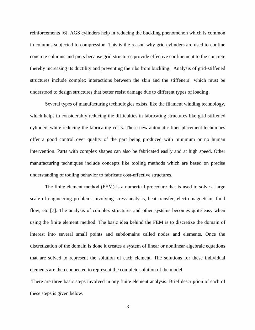
understand the behavior of the composite grid structures like the failure mechanisms and analyze
their performance. The improved understanding enhances the possibility of improving the
efficiency of the structure by taking maximum advantage of their unique properties.
Page 17
6
Chapter 2
Literature Review
Advanced Grid Stiffened (AGS) structures have long been of interest as a possible solution to
many of the problems inherent with traditional laminated composites. They possess excellent
resistance to impact damage, delamination, and crack propagation [8] and have several unique
properties as a result of combination of the grid configuration and unidirectional fibers. AGS
structures are used by aeronautical engineers to stiffen spacecraft solar cell arrays and by
structural engineers to design structural members [9]. With the advent of new manufacturing and
design techniques, the technology behind these structures has progressed significantly [10]. The
paper by Huybrechts and Meink of US Air Force Phillips Lab discusses a brief history of AGS
composites and new manufacturing methods like SnapSat concept from Composite Optics Inc.,
and the Tooling Reinforced Integral Grid (TRIG) concept from Stanford University. Huybrechts
et al. [11,12] at the Air Force Research Laboratory have developed effective methods called the
Hybrid Tooling concept for fabricating high quality and low cost AGS structures. These methods
rely on proper understanding of the tooling behavior during cure to achieve proper consolidation,
often determined through trial and error. An analytical model was developed by Kidane et al.
[13,14] to determine the buckling load of grid stiffened composite cylinders. The developed
analytical model was shown to be reliable by performing buckling load tests. Parametric tests
were also conducted to show the effect of different parameters on the buckling load. Another
such model, the integrated equivalent stiffness model, was developed by Chen and Tsai [15] to
describe a grid structure and to optimally design them. This method proved to be quite accurate
for displacements and for stresses or strains. For more accurate results, this equivalent stiffness
Page 18
7
can be incorporated with exact FEM modeling to obtain refined stress analysis. To better
understand the damage mechanism of CFRP panels subjected to impact loads, static indentation
and impact testing were conducted by Found et al. [16]. It was observed that the ring stiffeners
reduced the backface cracking and delamination of the panels, suggesting their use as crack
arresters.
A design strategy for optimal design of composite grid-stiffened cylinders subject to local
and global buckling constraints was developed by Jaunky et al. [17] using a discrete optimizer
based on a genetic algorithm. Several design variables like the axial and transverse stiffener
spacing, stiffener height and thickness, stiffening configuration, etc. were used in the study and
the design optimization process was adapted to identify the best suited configuration for the grid
stiffened cylinder. Saafi et al. [18] have conducted experimental and analytical investigations on
the performance of composite grids. The effect of the type of composite material and the spacing
of the stiffeners on the grid cylinder was also determined by varying these test variables. The
local and global buckling behavior of IsoTruss composite structures with changing bay length
was examined by Jensen et al. [19]. The test results show that the local buckling depends on bay
length, with higher buckling loads observed for shorter bay lengths. Global buckling, on the
other hand, is independent of bay length; although increasing the bay length reduces the weight
of an IsoTruss. Analytical/Experimental investigations were carried out by Gibson et al. [20] to
understand the energy absorption characteristics of grid-stiffened structures. The test results and
the simulations show that these types of structures have excellent damage tolerance and that most
of the energy absorption occurs beyond initial failure.
An efficient and accurate buckling analysis method for general grid-stiffened panels
subjected to combined in-plane loading is needed in order understand the complex skin-stiffener
Page 19
8
interaction that are common in aircraft fuselage and wing structures. The work carried out by
Jaunky et al. [21] includes formulating an improved smeared stiffener theory for stiffened panels
that includes skin-stiffener interaction effects. The results from the numerical examples suggest
that the smeared stiffener theory with skin-stiffener interaction effects is a useful preliminary
design tool and results in buckling loads are more accurate than the results from the traditional
smeared stiffener approach. A comparison of composite structures was made with Advanced
Grid Stiffened (AGS) structures by Meink [22] to determine the practicality of replacing
sandwich structures with grid structures. It was determined that the advantage of the AGS
structure lies in the manufacturing. They have been shown to be well suited for automation,
giving them obvious advantages under production environment. Grid structures also offer
advantages in damage tolerance and non-destructive evaluation (NDE).
External confinement of concrete by means of high-strength fiber composites can
significantly enhance its strength and ductility as well as result in large energy absorption
capacity [23]. One of the unique characteristics of confinement with fiber composite is that,
unlike steel, FRP curtails the dilation tendency of concrete. It has also been observed in the
experiments conducted by Li et al. [24] that the strength, ductility and failure mode of FRP
wrapped concrete cylinders depend on the fiber orientation. Fibers oriented at a certain angle in
between the hoop direction and axial direction may result in strength lower than fibers along
hoop or axial direction. Confinement of concrete by grid-stiffened cylinders was carried out by
Saafi et al. [25]. The behavior of grid confined concrete columns was compared with that of the
steel confined concrete columns. The test results showed that the strength of the grid confined
concrete was higher than the steel confined concrete because of its unique confinement
mechanism. Michael et al. [26] conducted experiments on concrete cylinders confined by
Page 20
9
embedded cylindrical FRP grid to determine the ability of these grids to provide confinement to
the concrete and to analyze the post-peak behavior of these structures when tested in
compression to failure. It was found that the grid confinement resulted in an increase in the
concrete strength and a significant improvement was observed in the ductility of the concrete
cylinders.
Li [27] introduced a concept of encasing concrete in a FRP wrapped steel grid tube. He
found that the grid tube encased concrete cylinder has all the advantages of conventional FRP
tube or steel tube encased concrete cylinders like serving as a stay-in-place formwork; he also
found that the elastic range has been increased significantly due to the mechanical interlocking
between the grid skeleton and the concrete core. The transition zone did not occur until the stress
was well above the unconfined concrete strength. This concept has also been validated by a fully
FRP grid tube encased concrete cylinder [28]. However, it is noted that, in the previous study
[28], (1) the FRP grid tube was fabricated by the hand lay-up technology; (2) only three FRP grid
tube encased concrete cylinders were tested and a parametric study was unavailable; (3) the
parametric study by the finite element analysis was based on a simplified model, i.e., the
concrete in the bays was assumed as a Winkler foundation and the concrete core was replaced by
an internal pressure.
The purpose of this study is thus to improve the previous study by (1) developing an
automatic fabrication technology by filament winding; (2) experimentally investigating the
various design parameters on the structural behavior of FRP grid tube encased concrete
cylinders; and (3) conducting finite element analysis by considering the nonlinear behavior of
concrete. A list of other useful references [37, 38, 39, 40, 41, and 42] that were considered
during the study can be found in the References section.
Page 21
10
Chapter 3
Manufacturing and Characterization
3.1 Raw Material Properties
The AGS circular cylinders were manufactured using a two-axis filament winding machine.
Glass fibers and vinyl ester resin were used in fabrication. The physical/mechanical properties of
the raw materials used are given in Table 1. These values are obtained from the manufacturer‟s
data sheet. Some of the advantages of fiberglass are that they are cheaper than other fibers like
Kevlar or carbon fibers. It can also undergo more elongation before breaking unlike carbon
fibers. The reason for using vinyl ester resin as a matrix is that it is chemically stable in an
alkaline environment like concrete.
Table 1: Physical/Mechanical properties of the raw materials used
Material
Tensile
Strength
(MPa)
Modulus of
Elasticity
(GPa)
Density
(g/cm3)
Poisson‟s
Ratio
Shear
Modulus
(GPa)
Vinyl Ester Resin
86
3.2
1.14
0.35
1.18
E-glass Fiber
2277
75.15
2.62
0.25
30.06
Page 22
11
3.2 Filament Winding Technique
There are several manufacturing techniques available for the fabrication of composite structures
viz. resin transfer molding, pultrusion, filament winding, etc. The filament winding technique
offers advantage over other techniques in that it is easy to fabricate, it is fast and parts can be
manufactured automatically and at lower cost
The filament winding process basically consists of wrapping a continuous resin
impregnated fiber rovings onto the rotating mandrel. A schematic of the filament winding
process is shown in Figure 1. This method offers good control over fiber placement and
uniformity of the structure. The final shape of the product depends on the shape of the mandrel.
Some of the applications are in the fabrication of cylindrical and spherical pressure vessels,
rocket motor casings, helicopter blades, large underground storage tanks, etc. Filament winding
machines with higher degrees of freedom can be used to manufacture more complex parts such
as tee-joints and elbows. Figure 2 shows the filament winding machine used during the
fabrication.
Figure 1: Schematic of the filament winding process
Page 23
12
Figure 2: “Little Hornet” Two-axis filament winding machine
3.3 Fabrication
A collapsible mandrel with pin system (Fig. 3) was used to fabricate all the AGS circular
cylinders. This system was employed after investigating other techniques which failed to give a
good grid layout. To prepare the collapsible mandrel, a 102 mm internal diameter FRP pipe was
cut into two halves. Holes were drilled at the desired location to accommodate the pins. The pins
basically act as guides along which the fibers are arranged to form the grid pattern. The pattern
and the number of holes to be drilled on the two halves of the FRP pipe depends on the
parameters of the grid being manufactured such as bay area, rib thickness etc.
A mold releasing agent is first sprayed on the actual mandrel of the filament winding
machine. The two halves of the collapsible mandrel are then mounted on it and tied at the ends.
A Mylar sheet is wrapped around this collapsible mandrel for easy removal of mold from the
grid. The rolled pins are then hammered into the holes of the mandrel.
Page 24
13
Figure 3: Collapsible mandrel with holes
To start the fabrication, the resin is first prepared and poured into a resin bath of the
filament winding machine. The resin used is DERAKANE 510C-350 DOW epoxy vinyl ester
resin. The composition of resin contains 98% vinyl ester + 2% (MEKP + Cobalt Napthanate).
The gel time of the resin can be increased by adding gel time retarder. All these constituents are
carefully added to the resin and mixed using a stirrer. The fiber rovings are then passed through
the resin bath through a comb like device which helps in better wetting of each fiber in the
rovings. These resin-impregnated fibers are passed through a pay-out eye which squeezes out the
extra resin. The fibers are then wound onto the rotating mandrel through the pins to get grids of
the desired pattern. Even though the process is entirely automatic some human intervention is
required while placing the fibers over the pins.
The desired pattern of the grid is generated by controlling the transverse speed of the
carriage and the winding speed of the mandrel. These parameters are in turn controlled using the
Page 25
14
control unit of the filament winding machine. This basically involves inputting to the control unit
a set of predetermined parameters like the carriage speed, the winding angle, etc in the form of a
code. Once all the input parameters are given to the control unit, the machine can be started and
the fabrication is done automatically.
After allowing the grid structure to cure, an outer composite layer (skin) is wrapped
around it to make the grid cylinder a grid tube. This was also done using the filament winding
machine. Samples were fabricated with skin having three different orientations of 0o, 35
o, and
75o. This entire structure is again allowed to cure before demolding and cutting into samples of
desired length. Figure 4 & 5 show a grid structure without and with the skin mounted on the
collapsible mandrel.
Figure 4: Grid structure on the collapsible mandrel with pin
Page 26
15
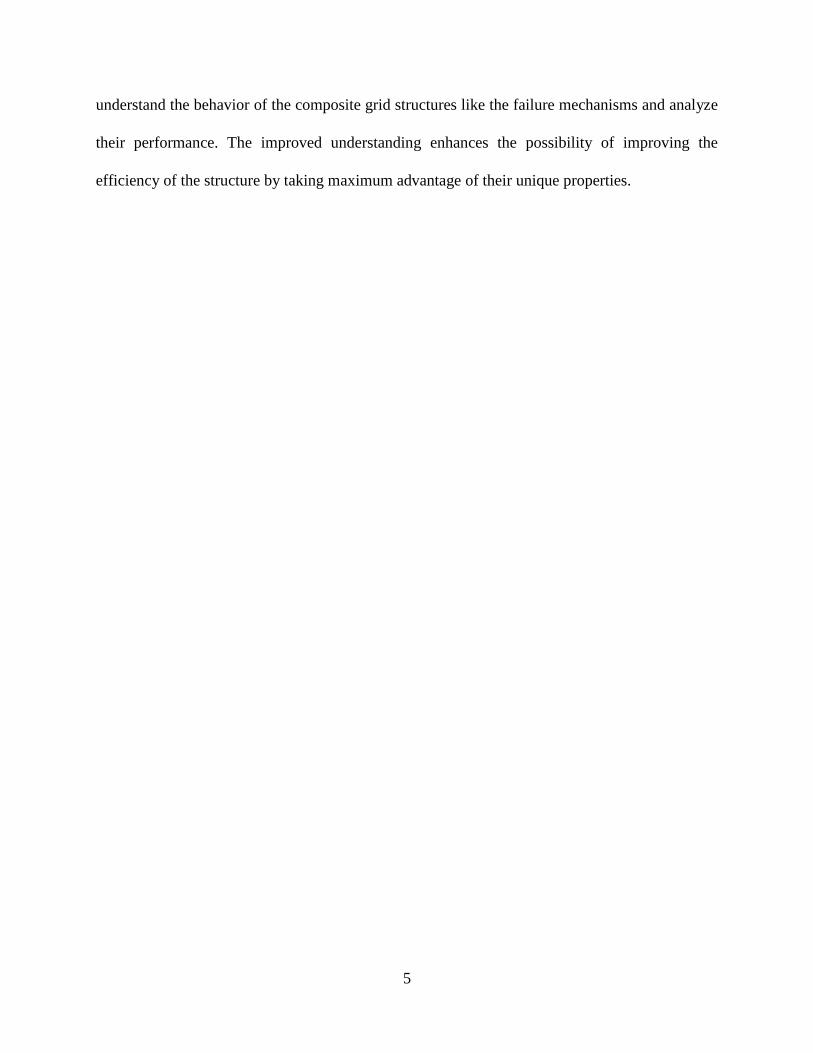
Figure 5: Grid structure with the skin on the filament winding machine mandrel
3.4 Mold Removal System
After fabrication, the specimen was allowed to cure on the rotating mandrel. Since it was very
difficult to manually pull the grid structure out of the filament winding mandrel, a mold removal
system (Figures 6 and 7) was built specifically for this purpose. It consists of a long wooden
platform with rollers attached on top of it for the mandrel to move. This entire setup is fixed to
the ground. A utility winch with a jump start system was utilized to pull the actual steel mandrel
leaving behind just the collapsible mandrel with the grid structure on it. This collapsible mandrel,
when pressed onto each other collapses and can be easily removed from the grid structure
(Figures 8 and 9).
Page 27
16
Figure 6: Jumpstart system and utility winch mounted on the wooden platform
Figure 7: Mold removal system
Page 28
17
Figure 8: Collapsible mandrel Figure 9: Collapsible mandrel and grid structure
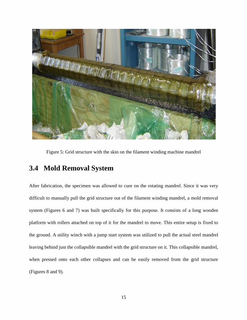
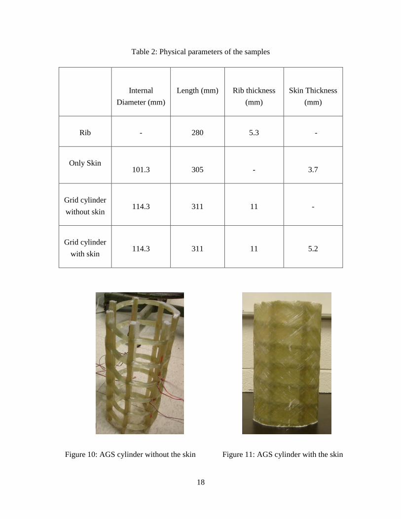
All the specimens that were manufactured were 305 mm in length with an internal diameter of
114.3 mm. Table 2 provides the geometrical parameters of the fabricated cylinders. Some of the
samples were wrapped with an outer composite layer (skin). The same raw materials were used
in the fabrication of the skin. Figures 10 and 11 show grid stiffened cylinders without and with
skin.
Page 29
18
Table 2: Physical parameters of the samples
Internal
Diameter (mm)
Length (mm)
Rib thickness
(mm)
Skin Thickness
(mm)
Rib
-
280
5.3
-
Only Skin
101.3
305
-
3.7
Grid cylinder
without skin
114.3
311
11
-
Grid cylinder
with skin
114.3
311
11
5.2
Figure 10: AGS cylinder without the skin Figure 11: AGS cylinder with the skin
Page 30
19
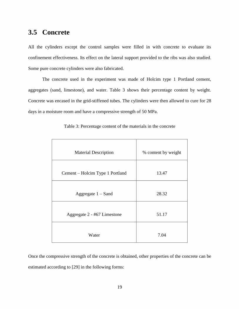
3.5 Concrete
All the cylinders except the control samples were filled in with concrete to evaluate its
confinement effectiveness. Its effect on the lateral support provided to the ribs was also studied.
Some pure concrete cylinders were also fabricated.
The concrete used in the experiment was made of Holcim type 1 Portland cement,
aggregates (sand, limestone), and water. Table 3 shows their percentage content by weight.
Concrete was encased in the grid-stiffened tubes. The cylinders were then allowed to cure for 28
days in a moisture room and have a compressive strength of 50 MPa.
Table 3: Percentage content of the materials in the concrete
Material Description
% content by weight
Cement – Holcim Type 1 Portland
13.47
Aggregate 1 – Sand
28.32
Aggregate 2 - #67 Limestone
51.17
Water
7.04
Once the compressive strength of the concrete is obtained, other properties of the concrete can be
estimated according to [29] in the following forms:
Page 31
20
Modulus of Elasticity ( ), = 4732 MPa
Uniaxial tensile strength (modulus of rupture) ( ), = 0.623 MPa
where, = compressive strength of concrete (psi)
The Poisson‟s ratio ( ) is assumed to be = 0.2
Table 4 gives the properties of unconfined concrete.
Table 4: Properties of the concrete
(MPa)
(MPa)
(GPa)
50.85
4.44
33.74
0.2
3.6 Burn-Out Test
The fiber volume fraction of the samples was found out using the burn-out test. ASTM D2584
(Standard Test Method for Ignition Loss of Cured Reinforced Resins) standard was used to carry
out the test. The fiber volume fractions for both skin and the ribs are given in Table 5.
A minimum of three specimens are needed from the sample for the test. The weight of a
dry and clean crucible is recorded first. Specimens are then placed in the crucibles and
weighed again . The crucibles with specimens are heated in a furnace to 565oC for about 2
hours or until the resin is completely burnt out. Remove the crucibles from the furnace and cool
Page 32
21
it to room temperature. The post burnout mass is measured . The volume fraction of the
fiber is then calculated using the following procedure.
From the above calculations, the volume fractions of fibers and resin is given by
Page 33
22
Table 5: Volume fraction of the fibers
Fiber volume fraction ( )
Ribs only
0.27
Skin only
0.48
Node only
0.54
3.7 Mechanical Properties of the AGS Cylinders
Once the fiber volume fraction is determined, the mechanical properties can be predicted by the
rule-of-mixture‟s method. The values of the elastic modulus in the longitudinal and transverse
directions ( ), the shear modulus ( ) and the Poisson‟s ratio ( )
of the composite AGS structure are calculated using the rule of mixtures as follows [30, 31].
Page 34
23
= +
where,
= Elastic modulus of the fiber
= Elastic modulus of the resin
= Shear modulus of the fiber
= Shear modulus of the resin
= Poisson‟s ratio of the fiber
= Poisson‟s ratio of the resin
= Volume fraction of the fiber
= Volume fraction of the resin
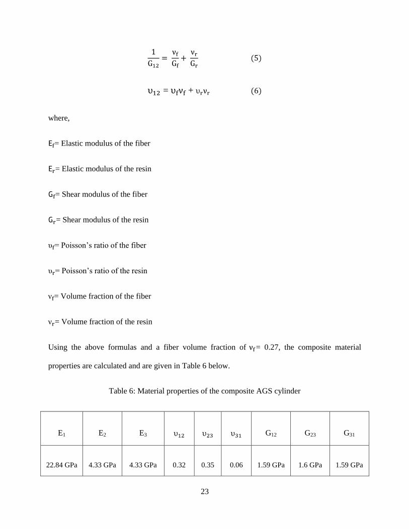
Using the above formulas and a fiber volume fraction of = 0.27, the composite material
properties are calculated and are given in Table 6 below.
Table 6: Material properties of the composite AGS cylinder
E1
E2
E3
G12
G23
G31
22.84 GPa
4.33 GPa
4.33 GPa
0.32
0.35
0.06
1.59 GPa
1.6 GPa
1.59 GPa
Page 35
24
Tables 7 & 8 give the material properties of nodes and skin. These properties are helpful during
the finite element modeling phase. The same volume fraction of fibers was used in the
calculation of the following material properties.
Table 7: Material properties of the nodes
E1
E2
E3
G12
G23
G31
42.02 GPa
6.76 GPa
6.76 GPa
0.29
0.35
0.046
2.45 GPa
2.5 GPa
2.45 GPa
Table 8: Material properties of the skin
E1
E2
E3
G12
G23
G31
37.73 GPa
5.92 GPa
5.92 GPa
0.3
0.35
0.047
2.18 GPa
2.19 GPa
2.19 GPa
Page 36
25
Chapter 4
Testing and Analysis
The fabricated advanced grid-stiffened cylinders were compression tested as this generally is the
type of loading that these kinds of structures are subjected to. The compression tests were
performed on both the control samples and the concrete filled grid-stiffened cylinders. As
explained earlier, all the specimens were fabricated using filament winding process. The testing
of the cylinders was done on a FORNEY machine which has a capacity of 2669 KN. The
compression tests were carried out in accordance with ASTM D695 standard. The loading rate
was 1.27 mm/min. The specimens were placed between two rigid steel plates with a cushioning
material between the plates and the cylinder and were subjected to uniaxial compressive loading.
The reason a cushioning material was used is because the end surfaces of the cylinders may not
be flat and the cushioning material helps in balancing the samples to stay up-straight so that the
load is applied without any eccentricity. The cushioning material also helps in avoiding
premature failure of the ribs at the ends of the samples. The test set-up is shown in Figure 12.
Figure 12: FORNEY compression testing machine
Page 37
26
4.1 Instrumentation
The load-displacement curves data were directly obtained from the compression testing machine
which was connected to a personal computer through a data acquisition system. These data can
later be used to construct either load-displacement or stress-strain graphs, whichever is required.
Several strain gages were mounted on different locations on the cylinders to obtain the real time
local strain distributions in the grid structure. A YOKOGAWA DC100 data acquisition unit was
used to obtain the strain gage readings. Figure 13 shows the strain gage data acquisition system
used in the experiments. Strain gages were placed on the samples in such a way that they record
data at all the important locations on the structure. Strain gages were placed on the longitudinal
ribs, the hoop ribs as well as on the crossover points of longitudinal and hoop ribs, i.e. the nodes.
They were also attached to the skin on both the inside and the outside of the cylinders. Figures
14 and 15 show the arrangement of the strain gages on the samples.
Figure 13: YOKOGAWA DC100 data acquisition system
Page 38
27
(a) Strain gages on the skin cylinder (b) Strain gages on the grid-stiffened cylinder
Figure 14: Mounted strain gages
(a) Strain gages pasted outside (b) Strain gages pasted inside
Figure 15: Strain gages pasted on the skin of the grid-stiffened cylinder
Page 39
28
4.2 Results and Analysis
4.2.1 Control Samples
Figure 16 shows specimens under compression testing. The typical axial load-displacement
curves for the AGS cylinders are shown in Figure 17. It can be seen from Table 9 that the
maximum load carried by a single composite element i.e. a rib is 14.1 KN. The rib was subjected
to compression until it buckled. During testing it was observed that the failure mode associated
with this type of element is the global buckling of the structure. As can be seen from the graph in
Figure 17, the stress in the rib increases until failure and then drops suddenly which indicates
that the rib has suddenly buckled. A rib subjected to compression is shown in Figure 18.
(a) (b)
Figure 16: (a), (b) Specimens under compression testing
Page 40
29
Displacement (mm)
0 2 4 6 8 10 12 14 16
Load
(K
N)
0
50
100
150
200
only skin
without skin(single rib)
without skin(grid cylinder)
with skin
Figure 17: Load-displacement graph of the grid cylinders
Figure 18: Rib under compression
Page 41
30
Table 9: Load carrying capacities of the composite structures
Peak load (KN)
Only skin (0o fiber orientation)
54.4
Without skin (grid cylinder)
99.1
Without skin (single rib)
14.1
With skin (a grid cylinder wrapped with skin having 0° fiber angle)
198.1
Now consider the grid cylinder without skin with ribs in the hoop direction. The ribs in the hoop
direction run spirally along the axial stiffeners. The maximum load carried by this type of
structure is 99.1 KN. For a single rib, the peak load is 14.1 KN. It is noted that for the grid
cylinder, there are a total of 7 axial ribs. Therefore, it is estimated that if all the 7 axial ribs carry
load simultaneously, as in the case of the grid cylinder, the peak load would be 7 14.1 = 98.7
(KN), which would be very close to the grid cylinder (99.1KN). Therefore, the introduction of
the hoop ribs did not contribute to increase the peak load, or the load carrying capacity of the
grid cylinder. This actually is not true. The reason is that the boundary condition for the grid
cylinder is close to simply supported, while the boundary condition for the rib is clamped. If both
the grid cylinder and the rib use the same boundary condition, the grid cylinder will have a much
Page 42
31
larger axial peak load than the 7 ribs combined together. This definitely shows the positive
composite action between the axial and hoop ribs. Actually, the failure mode is also different.
The grid cylinder fails by local buckling and crippling, while the rib fails by global buckling; see
Figure 19 for the grid cylinder and Figure 18 for the rib. The contribution of the hoop ribs to the
axial ribs also comes after the peak load. From Figure 17, it is seen that the grid cylinder fails by
progressive failure; the load experiences a rebound, instead of a monotonic descending.
Figure 19: Localized rib buckling and stiffener crippling of the grid structure
From Table 9, it is seen that a positive composite action between the skin and the grid is also
developed. The sum of the peak load of the skin and the grid cylinder is 54.4 + 99.1 = 153.5
(KN). Obviously, this is smaller than the integrated cylinder (grid cylinder wrapped with skin),
Page 43
32
which is equal to 198.1 KN. The reason for this is that the skin and the grid tube carry the
applied load collaboratively. The skin provides lateral confinement to the grid cylinder thereby
increasing its load carrying capacity and its resistance to early failure. It is expected that the peak
load can be further increased if the skin and the grid tube have better compatibility, i.e., in
stiffness and strength. Among all the compatibility requirements, the most obvious factor is the
axial stiffness. In the test specimens, the fibers in the skin aligned along the hoop direction.
Therefore, the axial stiffness of the skin is smaller than that of the grid tube, which has a large
amount of fibers in the axial direction. Consequently, the grid tube will have a larger share of
load. The skin only shares a small portion of load. This tendency goes by until some damage
occurs in the grid tube, which leads to a reduction of stiffness in the axial direction and a
redistribution of load. Some load carried by the grid tube will be shifted to the skin until the skin
fails. This causes the failure of the whole cylinder. Figure 20 shows the failure mode of grid with
skin.
It is expected that if the axial stiffness of the skin is increased, the peak load of the
integrated cylinder will increase. This is exactly the case. In addition to the 0o angle skin, two
other groups of samples were fabricated using the same manufacturing procedure but with skin
wound at 35o and 75
o. From the results of the compression testing, it is seen that peak load
increases with the 35o and 75
o fiber orientation; see Figure 21 and Table 10. Of course, the 75
o
skin does not show a higher peak load than the 35o skin. The reason for this is that axial stiffness
is only one requirement for the compatibility. Other requirements such as hoop stiffness,
strength, etc. also take effect.
Page 44
33
(a) (b)
Figure 20: (a), (b) Failure of the skin and the ribs of the grid cylinder wound with the skin
Strain
-0.01 0.00 0.01 0.02 0.03 0.04 0.05 0.06
Str
ess
(MP
a)
0
50
100
150
2000
o skin
35o skin
75o skin
Figure 21: Variation of the stress in the grid cylinder with the skin angle
Page 45
34
Table 10: Peak loads carried by the grid structures with the skin wound at 0o, 35
o and 75
o
Skin angle
Peak load (KN)
0o
198.1
35o
530.5
75o
521.8
4.2.2 Concrete Filled Grid Stiffened Cylinders
This section analyzes the interaction of AGS cylinders when filled with a filling material such as
concrete. The graph in Figure 22 shows the load carrying capacity of a pure concrete cylinder, a
grid cylinder with skin and a grid tube encased concrete cylinder. The maximum loads carried by
these samples are shown in Table 11. This increase in the load carrying capability is due to the
result of the interlocking mechanism of the concrete teeth with the fiber reinforced grid. The
concrete, when poured inside the cylinder, flows into the surrounding bay areas and forms a
strong interlocking with adjacent ribs. This type of bond proves to be quite strong in enhancing
the confinement effectiveness of the grid stiffened cylinders. The AGS cylinder confines the
concrete core inside it and resists its lateral expansion leading to an increase in the strength of the
confined concrete cylinders.
Page 46
35
Strain
-0.01 0.00 0.01 0.02 0.03 0.04 0.05 0.06
Str
ess
(MP
a)
0
20
40
60
80
100
120
140
160
180
grid cylinder with skin
concrete confined grid cylinder
pure concrete cylider
Figure 22: Stress-strain graph for a grid cylinder with skin and a confined concrete cylinder
Table 11: Maximum load carried by the samples
Peak load (KN)
Pure concrete cylinder
474.1
Grid cylinder with skin (35°)
530.5
Grid tube encased concrete cylinder
2180.6
Page 47
36
The development of composite action from a single rib to the grid tube encased concrete cylinder
can be further summarized in Table 12. From Table 12, the composite action between the
structural components is positive or constructive. The grid cylinder sees the composite action
between the axial ribs and the hoop ribs; the grid tube with skin sees that composite action
between the skin and the grid cylinder; the grid tube encased concrete cylinder sees the
composite action between the grid tube and the concrete core. This gradual development of the
composite action clearly validates the proposed concept. It also indicates the important design
variables that need to be considered.
Table 12: Schematic of the load carrying capacity of the composite elements
Peak load (KN)
Only Skin
54.4
(Table 12 continued)
Page 48
37
Without Skin
14.1
(without
considering hoop
direction ribs)
99.1
(with ribs in hoop
direction
considered)
Grid with skin
530.5
(Table 12 continued)
Page 49
38
Pure Concrete
474.1
Grid cylinder
confined with
concrete
2180.6
Page 50
39
4.3 Effect of Design Variables
As discussed in the Manufacturing and Characterization chapter, several grid-stiffened cylinders
were fabricated by varying design variables such as skin thickness, rib thickness and bay area.
These physical parameters were easily varied with little or no change in the fabrication
procedure. The raw materials used were also the same. All the specimens were filled with
concrete and subjected to uniaxial compressive load. The results from the experiments were
analyzed and the effect of each of these parameters on the structural efficiency of the cylinders
was evaluated. During fabrication, only one design variable was varied at a time by keeping all
other variables constant. This helps in easily determining what effect a particular variable has on
the load carrying capacity of the cylinder. The following sections present the analysis of
variations of these design parameters.
4.3.1 Variation of Skin Thickness
The experimental results show that the load carrying capacity of the confined concrete grid
cylinders increases with the increase in the skin thickness. This can be attributed to the lateral
support provided to the grid cylinder by the skin. During fabrication, cylinders were
manufactured with three skin thicknesses, i.e. 2 layers, 3 layers and 4 layers of skin. As can be
seen from Table 13, the cylinder with a 4 layer skin has the highest load carrying capacity when
compared to the cylinders with 2 or 3 layers of skin. This suggests that the skin not only serves a
stay-in-place formwork during construction but it also plays an important structural role, i.e.,
confining the grid cylinder and the concrete within the bays, similar to the findings previously
[27, 28].
Page 51
40
Table 13: Load carrying capacity for cylinders with different skin thicknesses
Load carrying capacity (KN)
2 plies
1954.6
3 plies
2060.7
4 plies
2174.7
4.3.2 Variation of Rib Thickness
Increasing the rib thickness increases the load carrying capacity of the cylinders. The thicknesses
of the ribs that were investigated during the experiments were 6.4 mm, 12.7 mm and 19.1 mm.
The cylinder with the largest thickness was able to withstand more loads when compared to other
cylinders. Table 14 shows the load carrying capacities for cylinders with different rib
thicknesses. However, it is observed that this increase in load carrying capacity is not a linear
function of the rib thickness. The rate of increase reduces as the rib thickness increases. This
suggests that further thickening the ribs will reduce its efficiency.
Table 14: Load carrying capacity for cylinders with different rib thicknesses
Rib thickness (mm)
Load carrying capacity (KN)
6.4
1809.3
12.7
2060.7
19.1
2215.8
Page 52
41
4.3.3 Variation of Bay Area
Cylinders with bay area of 25.4 mm2, 38.1 mm
2 and 50.8 mm
2 were fabricated for experimental
analysis. The results from the tests indicate that the load carrying capacity of the cylinders
decreases with the increase in bay area. Table 15 shows the load carrying capacities for cylinders
with different bay areas. A possible reason for this is that, as the bay area increases, the
confinement to the concrete within the bays by the ribs becomes weaker. As a result, the concrete
within the bays will be easily damaged (cracked and crushed), which provides a „hole‟ for the
concrete core to damage and to flow into it.
Table 15: Load carrying capacity of cylinders with different bay areas
Bay area (mm
2)
Load carrying capacity (KN)
25.4
2120.4
38.1
2060.7
50.8
1726.5
Page 53
42
Chapter 5
Finite Element Modeling
Finite element method is a powerful analytical tool to effectively predict the behavior and
simulate the response of composite structures. This chapter presents finite element modeling of
advanced grid-stiffened cylinders using ANSYS 10.0 finite element software. The developed
model was used to validate the experimental results. This validated model was then used to
conduct parametric studies to analyze the effect of various parameters on the system.
Figure 23: Finite element model of the grid structure without the skin
Page 54
43
Figure 24: Finite element model of the grid structure with the skin
A 3D model of AGS cylinders without and with the skin is shown in Figures 23 and 24. The
hoop ribs were modeled as having helical geometry, which is the exact configuration that was
obtained during fabrication and the axial ribs were modeled in the longitudinal direction. The
crossover points of the longitudinal and the hoop ribs, i.e. the nodes, were modeled as individual
entities and were given different material properties and other such attributes. The node is an
important element of the grid structure with more stress concentration at their locations. They
also have larger stiffness when compared to the ribs and therefore are much stronger; hence it is
essential that they be treated separately from the structure to get accurate results. The skin was
added around the grid structure and glued, assuming a perfect bond between the two.
Page 55
44
The fibers in the axial stiffeners were oriented along their length and ones in the hoop
ribs along their helical direction. The skin was modeled as having an angle of 0o. A cylindrical
coordinate system was defined to input the orthotropic material properties for the hoop ribs and
the skin. Two different real constant tables were created for the longitudinal and the hoop
stiffeners. The material properties for the ribs, nodes and skin are given in previous chapter. The
skin and the stiffeners were glued together which upon meshing merges their element nodes at
the interface. Merging the nodes helps the structure to behave as a continuous one with
compatible displacements.
5.1 Element Types
The ribs were modeled using 3D layered SOLID191 element. The element is defined by 20
nodes having three degrees of freedom per node: translations in the nodal x, y, and z directions.
SOLID191 has stress stiffening capabilities and takes into account orthotropic properties. Fig 25
shows its element coordinate system and geometry [32].
Figure 25: SOLID191 geometry and coordinate system
A layered SOLID46 element was used to model the skin. The element has three degrees
of freedom at each node: translations in the nodal x, y, and z directions. The geometry, node
locations, and the coordinate system for this element are shown in Figure 26. The element is
Page 56
45
defined by eight nodes, layer thicknesses, layer material direction angles, and orthotropic
material properties.
Figure 26: SOLID46 geometry and coordinate system
SOLID65 was used for 3D modeling of concrete with or without reinforcing bars. The
element is capable of cracking in tension and crushing in compression. One of the main
applications of this element is in the modeling of concrete to be reinforced with composite
materials. The most important aspect of this element is the treatment of nonlinear material
properties. The element is defined by 8 nodes with three degrees of freedom at each node:
translation in nodal x, y and z directions and has isotropic material properties. The geometry,
node locations and coordinate systems for this element are shown in Figure 27.
Figure 27: SOLID65 geometry and coordinate system
Page 57
46
5.2 Drucker-Prager Criteria
In the present analysis, confined concrete was modeled as an elastic-perfectly plastic material
and was analyzed using a non-associative Drucker-Prager plasticity criterion. The existing
plasticity models require several parameters to effectively model the behavior of confined
concrete. The main advantage of Drucker-Prager (DP) type plasticity is that it minimizes the
number of parameters by assuming an elastic-perfectly plastic response. The required DP
parameters for analyzing concrete are:
1) Cohesion of the material (c)
2) Angle of internal friction ( )
3) Dilatancy angle ( )
One of the following methods is used to calculate the Drucker-Prager parameters
a) Richart et al. [33]
b) Mander et al. [34]
c) Samaan et al. [35]
d) Rochette and Labossi re et al. [36]
e) Direct input
The cohesion and internal friction angle for concrete are given by the following relations
where: = confinement effectiveness factor
Page 58
47
= unconfined concrete strength
For Richart et al. model the confinement effectiveness factor is taken as = 4.1 and the DP
parameters are calculated using the above formulae
From the model by Samaan et al. the confinement pressure ( ) is calculated using
where:
The corresponding confined concrete strength is found using
For Mander et al. model the proposed relation for confined concrete strength is
Once the confined concrete strength is calculated from either of the above two methods, the
confinement effectiveness factor is calculated from
From the above value of the DP parameters are evaluated from Equations 7 and 8.
Page 59
48
The DP parameters can also be directly calculated by Rochette and Labossi re et al. model from
the following equations
The method used by Richart et al. was used to calculate the Drucker-Prager criteria. These
parameters were then used in the finite element analysis of confined concrete cylinders. Table 16
shows the three calculated Drucker-Prager parameters.
Table 16: Drucker-Prager parameters
Cohesion of the material (c)
12.57 MPa
Angle of internal friction ( )
37.4o
Dilatancy angle ( )
0o
5.3 Boundary Conditions and Loading
The grid cylinder was modeled in such a way that the axis of the cylinder coincides with positive
z-axis and the bottom face lies in the x-y plane of the global coordinate system. The x-axis
Page 60
49
represents the radial direction and the y-axis represents the hoop direction of the cylinder. The
following boundary conditions were applied to the finite element model.
1) The bottom face of the cylinder was fixed , i.e. all the six degrees of freedom of that face
were constrained
2) The radial and circumferential displacements were constrained at the top face of the
cylinder
3) An uniaxial compressive pressure was applied on the top surface
5.4 Convergence Check
The accuracy of the finite element results can be checked by performing a convergence analysis.
The convergence check was performed on a finite element model of a control sample. Three
different mesh sizes were used for this purpose: coarse mesh (6.4 mm), medium mesh (5.1 mm)
and fine mesh (3.8 mm). The corresponding stresses (hoop direction stresses) resulting from the
above three analyses are denoted by , and . The results are said to converge if they
satisfy the following criteria
The following calculations show the convergence check analysis and it can be concluded that the
results from the analysis have converged.
Page 61
50
5.5 Nonlinear Analysis
Structures behave nonlinearly due to variety of reasons. Nonlinear behavior due to contact is one
such category. If a structure undergoes large deformations it behaves nonlinearly due to its
changing geometric configuration. Geometric nonlinearities are characterized by large
displacements or rotations. Nonlinear stress-strain relationships are the common cause for
material nonlinearities. Many factors influence the materials stress-strain properties like the load
history, external environment, etc. A nonlinear structural analysis was performed by taking into
account the nonlinear material behavior of the concrete. ANSYS performs the nonlinear analysis
by employing “Newton-Raphson” criteria. Using this approach, the load is subdivided into a
series of load increments and applied over several load steps. It is important to ensure that the
problem converges by using several features of the ANSYS like automatic load stepping,
bisection, etc.
A nonlinear stress-strain relationship of materials causes the structure‟s stiffness to
change at different levels of load. All of the nonlinear material properties can be incorporated
into the ANSYS analysis by using appropriate element type. The plastic response of the material
can be modeled using Drucker-Prager criteria as discussed in the earlier section. The uniaxial
compressive stress-strain for the concrete used in this study was constructed using the following
procedure [29].
Page 62
51
where: = stress at any strain
= strain at stress
= strain at the ultimate compressive strength
Figure 28 shows the simplified uniaxial compressive stress-strain relationship used in the model.
Figure 28: Stress-strain relationship for concrete
5.6 Finite Element Solution
5.6.1 Specimen Without Skin
The grid cylinder without skin forms the basic structure for both the grid cylinders with skin and
confined concrete cylinders. The grid plays an important role in confining the concrete and hence
its failure analysis is of quite importance. The experimental tests reveal that local stiffener
Page 63
52
crippling of the grid cylinder without the skin occurs at a stress of 118.35 MPa when subject to a
uniaxial compressive load. The results from the finite element analysis show that the structure
fails at 111.85 MPa. Figure 29 shows the stresses developed in the grid-stiffened cylinder
without skin.
Figure 29: Stresses in the grid structure without skin
5.6.2 Specimen With Skin
The skin is an important element of the advanced grid stiffened cylinder as it provides lateral
confinement to the grid structure hence improving its load carrying capacity apart from
protecting it from environmental deterioration. By subjecting the specimen to a uniaxial
Page 64
53
compressive load during the experiments it was observed that the skin fails at a stress of 74.34
MPa. A stress of 71.54 MPa was needed by the structure to fail according to finite element
analysis. Figure 30 shows the stresses in the grid cylinder with the skin.
Figure 30: Stresses in the grid structure with skin
5.6.3 FRP Grid Tube Confined Concrete Specimen
The computational time of the confined concrete finite element model was relatively long as
compared to the other models because of the nonlinear behavior of the concrete. The crushing
and cracking of the concrete can be plotted onto the model using one of the post-processing
features of ANSYS. Figure 31 shows the crushing and cracking of the finite element model of
Page 65
54
the concrete wherein the circles suggest that the concrete has cracked and the octagons suggest
that the concrete has crushed. The hoop stress developed in the FE model when it is subjected to
a uniaxial compressive load is 269.11 MPa. Figure 32 shows the stressed developed in the
model. The stress in the skin as predicted by the FE model is 77.16 MPa which is close to the
experimental result of 74.34 MPa. The compressive stress of the concrete developed by the FE
model is 57.4 MPa. The stresses developed in the individual components viz. concrete, FRP skin
and grid structure were also analyzed for failure and are shown in Figures 33, 34 and 35.
Figure 31: Crushing and cracking of the finite element model of the concrete
Page 66
55
Figure 32: Stresses developed in a FRP grid tube encased concrete cylinder
Figure 33: Stresses developed in the concrete
Page 67
56
Figure 34: Stresses developed in the skin
Figure 35: Stresses developed in the grid
Page 68
57
Figure 36 shows the comparison of stress-strain curves of the FRP grid tube encased concrete
cylinders obtained from the experimental results and FE analysis. The experimental sample used
here had a rib thickness of 12.7 mm, 38.1 mm2 bay area and 3 layers of skin. The linear portions
of both the curves almost follow the same path. As the load increases, the FEA curve deviates
from the experimental curve but has the same trend. This indicates the reliability of the FE
analysis to model the confined concrete cylinders. The model is more reliable in the elastic zone
of the curve than the plastic deformation zone.
Strain
0.00 0.01 0.02 0.03 0.04 0.05
Str
ess
(MP
a)
0
50
100
150
200
Experimental
FEA
Figure 36: Experimental and FEA stress-strain curves
Another similar analysis was done to compare the stress-strain curves from the experimental
results and the finite element analysis. A grid-stiffened cylinder of different configuration was
Page 69
58
chosen this time. The sample used in this case had a rib thickness of 12.7 mm, 25.4 mm2 bay
area, and 3 layers of skin. The results show a similar trend as was observed in the previous
analysis. This further increases the confidence level of the reliability of the FE model. Figure 37
shows the stress-strain curves obtained from the analysis.
Strain
0.00 0.01 0.02 0.03 0.04
Str
ess
(MP
a)
0
20
40
60
80
100
120
140
160
Experimental
FEA
Figure 37: Experimental and FEA stress-strain curves with a different configuration of confined
cylinder
Page 70
59
Chapter 6
Parametric Study
The accuracy of the finite element model in predicting the structural behavior of advanced grid
stiffened cylinder was shown in the previous chapter. As the model is shown to be reliable, it can
be used to conduct a parametric study. Parametric study involves analyzing the behavior of the
structure by varying the design variables that affect it. It also helps in optimizing the structure
and thus saving manufacturing costs. To this end, the critical variables that have a significant
influence on the structural behavior grid stiffened cylinders were identified as follows
1) Skin thickness
2) Material properties
3) Rib thickness
4) Bay area.
All the analyses were conducted by keeping the amount of material used as constant.
Hence, for the same weight of material, the influence of changing the design variables on the
load carrying capacity of the grid cylinders was investigated.
6.1 Grid Cylinders Without Concrete
6.1.1 Effect of Skin Thickness
The skin provides lateral confinement to the grid structure and the concrete inside it and hence is
one of the significant parameters that are required to be studied. Increasing the skin thickness
makes the structure more stable by reducing the stress developed in the structure. The mode of
Page 71
60
failure of the structure is also affected with the change in the thickness of the skin. The thickness
of the skin is varied from 1.27 mm to 25.4 mm to analyze how it affects the behavior of the grid
stiffened cylinders. The following graph shows the variation of the hoop stress in the grid
structure with the increase in skin thickness. It is clear from the graph that the load carrying
capacity of the cylinder increases with the increase in the thickness of the skin. However, the
overall tendency is that the efficiency will decreases as the skin thickness increases.
Skin thickness (mm)
0 5 10 15 20 25 30
Ho
op
str
ess
(MP
a)
30
40
50
60
70
80
90
Figure 38: Effect of skin thickness on the hoop stress
6.1.2 Effect of Material Properties
This section analyzes the effect of the material properties on the structural behavior of the grid
stiffened cylinder. The material property varied in this case is the longitudinal modulus of the
Page 72
61
skin. The modulus was linearly varied from 5 GPa to 55 GPa. The results show that increasing
the modulus decreases the hoop stress developed in the structure. With the increase in
longitudinal modulus the structure‟s stiffness increases which in turn makes the cylinder more
resistant to failure and increases its load carrying capacity. It is interesting to note that there is a
transition zone in Figure 39. This suggests that as the longitudinal stiffness of the skin increases,
more load will be shared by the skin so that less hoop stress will be developed in the ribs.
Longitudinal Modulus (GPa)
0 10 20 30 40 50 60
Ho
op
Str
ess
(MP
a)
56
58
60
62
64
66
68
70
Figure 39: Effect of material properties on the hoop stress
6.1.3 Effect of Rib Thickness
Another important design variable which has a considerable effect on the structure‟s response is
the rib thickness. The effect of thickness of the rib on the AGS cylinders was studied by varying
Page 73
62
its thickness from 6.35 mm to 25.4 mm. As expected, increasing the rib thickness enhances the
load carrying capacity of the cylinder, which is quite evident from the graph. It can also be
noticed from the plot that the structural efficiency of the cylinder increases with the increase in
rib thickness until 15 mm and then remains the same. Any further increase in the rib thickness
beyond this point will not have a considerable positive effect on the structures response.
Rib thickness (mm)
0 5 10 15 20 25 30
Ho
op
str
ess
(MP
a)
80
90
100
110
120
130
140
150
Figure 40: Effect of rib thickness on the hoop stress
6.1.4 Effect of Bay Area
The bay area of the cylinder is an important design parameter in the sense that along with its
surrounding ribs it can be treated as a unit cell of the grid structure where all the complex
mechanical interactions of concrete with the ribs take place. This bay area is what gives the
Page 74
63
cylinder its unique grid design. The concrete inside the bay area bonds with the surrounding ribs
increasing its resistance to failure. Since the fabricated cylinders have orthogonal design, the bay
area is almost square. The results from the FE analysis show that the load carrying capacity of
cylinder decreases with increase in the bay area.
Bay area (mm2)
20 25 30 35 40 45 50 55
Ho
op
str
ess
(MP
a)
80
85
90
95
100
105
110
115
Figure 41: Effect of bay area on the hoop stress
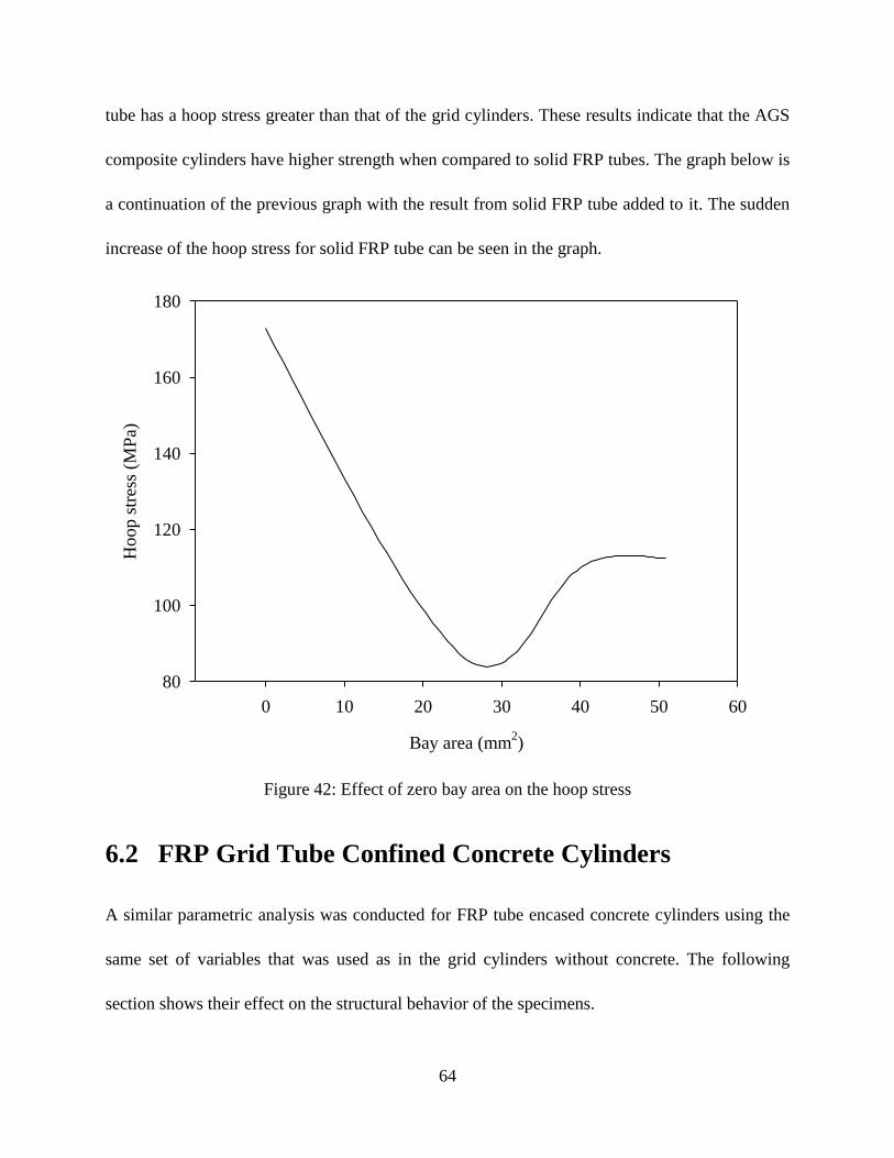
From the above graph, one might be mislead to believe that as the bay area decreases, the hoop
stress decreases linearly and is the lowest for a cylinder with zero bay area, i.e. a solid FRP tube.
To verify whether this indeed is the case, a finite element model was developed for a solid FRP
tube and analysis was done using the same set of input parameters and boundary conditions as
used in the grid-stiffened cylinder analysis. The results from the analysis show that the solid FRP
Page 75
64
tube has a hoop stress greater than that of the grid cylinders. These results indicate that the AGS
composite cylinders have higher strength when compared to solid FRP tubes. The graph below is
a continuation of the previous graph with the result from solid FRP tube added to it. The sudden
increase of the hoop stress for solid FRP tube can be seen in the graph.
Bay area (mm2)
0 10 20 30 40 50 60
Ho
op
str
ess
(MP
a)
80
100
120
140
160
180
Figure 42: Effect of zero bay area on the hoop stress
6.2 FRP Grid Tube Confined Concrete Cylinders
A similar parametric analysis was conducted for FRP tube encased concrete cylinders using the
same set of variables that was used as in the grid cylinders without concrete. The following
section shows their effect on the structural behavior of the specimens.
Page 76
65
6.2.1 Effect of Skin Thickness
As discussed earlier, wrapping a grid cylinder with skin enhances the structural efficiency of the
structure due to the lateral confinement provided by it. The effect of skin thickness on the
confined concrete cylinders was evaluated by using a finite element model. Figure 43 shows the
effect of skin thickness on the hoop stress. The results indicate that the load carrying capacity of
the cylinders increases with the increase in skin thickness. It is clear from the graph that with the
increase in the thickness of the skin the enhancement efficiency of the cylinders increases rapidly
until some point and that there is not much increase in efficiency beyond this point.
Skin thickness (mm)
0 5 10 15 20 25 30
Ho
op
str
ess
(MP
a)
140
160
180
200
220
240
260
280
300
Figure 43: Effect of skin thickness on the hoop stress
Page 77
66
6.2.2 Effect of Material Properties
This section shows the effect of longitudinal modulus of the skin on the load carrying capacity of
the grid cylinder. As can be seen from Figure 44 the structural efficiency of the cylinders
increases with the increase in modulus of the skin. This suggests that increasing the longitudinal
modulus of the skin increases its stiffness thereby allowing the skin to share more load and
increase the efficiency of the overall structure.
Longitudinal Modulus (GPa)
10 20 30 40 50 60 70 80
Ho
op
Str
ess
(MP
a)
100
200
300
400
Figure 44: Effect of material properties on the hoop stress
6.2.3 Effect of Rib Thickness
Figure 45 shows how rib thickness affects the load carrying capacity of the grid structure. The
hoop stress of the cylinders decreases with the increase in rib thickness. It can be seen from the
Page 78
67
graph that the load carrying capacity of the grid cylinders increases linearly with the increase in
rib thickness until some point and there is not much increase in the efficiency with any further
increase in the rib thickness beyond this point. Hence we can say that though the load carrying
capacity of the cylinders increases with the increase in rib thickness, the rib thickness will not
increase the efficiency of the cylinders beyond a certain critical point.
Rib thickness (mm)
5 10 15 20 25 30
Ho
op
str
ess
(MP
a)
200
220
240
260
280
300
320
340
360
Figure 45: Effect of rib thickness on the hoop stress
6.2.4 Effect of Bay Area
Increasing the bay area of the cylinders decreases the load carrying capacity of the grid cylinders.
Figure 46 shows the effect of bay area on the hoop stress. The bay area of the cylinders was
varied from 25.4 mm2 to 50.8 mm
2.
Page 79
68
Bay area (mm2)
10 20 30 40 50 60
Ho
op
str
ess
(MP
a)
160
180
200
220
240
260
280
300
320
Figure 46: Effect of bay area on the hoop stress
Again from the above graph, one might assume that as the bay area decreases, the hoop stress
decreases linearly and is the lowest for a cylinder with zero bay area, i.e. a solid FRP tube. The
following graph shows the effect zero bay area grid cylinder, i.e. a solid FRP tube on the hoop
stress of the confined concrete grid cylinder. Similar to the analysis conducted in the previous
section, a solid FRP tube was modeled and analyzed using ANSYS finite element software. The
same set of input parameters and boundary condition as used in the confined concrete cylinder
were used here. The results indicate that the hoop stress developed in the model is the highest for
a zero bay area cylinder, i.e. a solid FRP pipe. This indicates that the AGS cylinders have higher
strength when compared to solid FRP tubes. Figure 47 is a continuation of the previous graph
Page 80
69
with the result from solid FRP tube added to it. The sudden change of the hoop stress for a zero
bay area grid cylinder can be noted in the graph.
Bay area (mm2)
0 10 20 30 40 50 60
Ho
op
str
ess
(MP
a)
100
200
300
400
500
Figure 47: Effect of a zero bay area grid cylinder on the hoop stress
Page 81
70
Chapter 7
Conclusions and Recommendations
The manufacturing technology used, i.e. the filament winding technology, to fabricate Advanced
Grid Stiffened (AGS) composite cylinders has been presented and an explanation of its working
principle has been discussed. The fabrication procedure to fabricate these cylinders has also been
documented in detail. Compression tests were conducted on both control samples and concrete
filled grid stiffened cylinders. All the concrete confined cylinders were wrapped with an outer
composite layer called skin.
The analysis of experimental results show that the grid stiffened composite cylinders can
be effective load carrying members that have high resistance to failure and deformation when
compared to normal FRP tubes. The transverse support provided by the stiffeners in the hoop
direction resists the global buckling of the structure. The composite action between the stiffeners
and the skin helps in achieving the strength which is more than that of two individual
components put together. And in combination with fillers like concrete their strength increases
many folds. This is the result of their unique confinement mechanism in confining the concrete.
A 3-D finite element model was developed using ANSYS to analyze the behavior of grid
stiffened cylinders. The model was basically used to validate the test results. The non-linear
behavior of concrete was accounted for in the analysis by considering its stress-strain
relationship. A non-associative Drucker-Prager plasticity criterion was used to model the
behavior of concrete. Once the model was validated, it was used to perform a parametric analysis
on some of the parameters involved in the grid stiffened composite cylinders. The design
variables that were investigated in the analysis were skin thickness, material properties, rib
Page 82
71
thickness and bay area. These parameters were assumed to have a significant effect on the
strength properties of the cylinders.
The load carrying capacity of the cylinder increases with the increase in the skin
thickness and the rib thickness. This increase is limited only until some critical point is reached
after which any further increase would not result in significant enhancement in the strength of
the cylinder. With the increase in bay area the load carrying capacity of the structures decreases.
The experimental results show that the grid cylinders having skin wound at 0o fiber
orientation angle are not very effective. Grid structures with skin wound at a certain angle proved
to be quite efficient in increasing the load carrying capacity of the structures.
7.1 Future Work
Future research could focus on improving the quality of the grid-stiffened cylinders by
considering a new type of fabrication method. Grid structures can be fabricated with different
configurations and the effect of each of type of configuration on the structural efficiency of the
cylinders can be analyzed. The finite element model of the grid cylinders can be made more
accurate by considering other element types and practical boundary conditions. This finite
element model can then be utilized to conduct parametric analyses by investigating design
variables such as skin orientation angle, grid configuration, different material properties, etc.
Page 83
72
References
[1] Tim Heldt, Gerard Van Erp and Craig Cattell, “Fiber Composites in Infrastructure-
Applications and Issues”, Fiber Composite Design and Development, USQ, Queensland,
Australia.
[2] David Roylance, “Introduction to Composite Materials”, Department of Materials Science
and Engineering, MIT, Cambridge, MA 02139, March 24, 2000.
[3] Jaunky N., Knight N.F., Ambr D.R., “Optimal Design of General Stiffened Composite
Circular Cylinders for Global Buckling With Strength Constraints”, Composite Structures,
March 1998.
[4] Samuel Kidane., “Buckling Analysis of Grid Stiffened Composite Structures,” Thesis,
August 2002.
[5] Steven Huybrechts and Stephen E. Tsai, “Analysis and Behavior of Grid Structures”,
Composite Science and Technology 56 (1996) 1001-1005.
[6] A.P. Michael, H.R. Hamilton III, and M.H. Ansley, “Concrete Confinement Using Carbon
Fiber Reinforced Polymer Grid”, 7th International Symposium on Fiber-Reinforced (FRP)
Polymer Reinforcement for Concrete Structures, 2005
[7] Moaveni, Saeed, “Finite element analysis: theory and application with Ansys”, Prentice
Hall, 2nd
edition.
[8] Steven Huybrechts and Stephen E. Tsai, “Analysis and Behavior of Grid Structures”,
Composite Science and Technology 56 (1996) 1001-1005.
[9] Dinesh Maricherla, “Advanced Grid Stiffened Composite Structures”, Thesis, LSU.
[10] Steven M. Huybrechts, Troy E. Meink, Peter M. Wegner and Jeff M. Ganley,
“Manufacturing theory for advanced grid stiffened structures”, Composites Part A: applied
science and manufacturing, Volume 33, Number 2, pp. 155-161(7).
[11] Steven M. Huybrechts, Troy E. Meink, Peter M. Wegner and Jeff M. Ganley,
“Manufacturing theory for advanced grid stiffened structures”, Composites Part A: applied
science and manufacturing, Volume 33, Number 2, pp. 155-161(7).
[12] Huybrechts, S.M., Meink, T.E., 1997, “Advanced Grid Stiffened Structures for the Next
Generation of Launch Vehicles”, Proceeding of the 1997 IEEE Aerospace Conference, Feb
1-8 1997, Aspen, Colorado.
[13] Samuel, K., Li G., Helms J., Pang S.S., Woldesenbet E., “Buckling load analysis of grid
stiffened composite cylinders,” Composites Part B: Engineering, Volume 34, Number 1,
January 2003, pp. 1-9(9) August 2002.
Page 84
73
[14] Eyassu Woldesenbet , Samuel Kidane, Su-Seng Pang, “Optimization for buckling loads of
grid stiffened composite panels“, Composite Structures Volume 60, Issue 2 , May 2003,
Pages 159-169.
[15] Hong-Ji Chen and Stephen W. Tsai, “Analysis and Optimum Design of Composite Grid
Structures”, Journal of Composite Materials, Vol. 30, No. 4, 503-534 (1996).
[16] Found, M.S., Lamb, J.R., “Impact damage resistance of ring stiffened CFRP panels”,
Composites Science and Technology 66 (2006) 215–221.
[17] Jaunky, N., Knight N.F., Ambur D.R., “Optimal Design of Grid-Stiffened Composite
Panels Using Global and Local Buckling Analysis,” Journal of Aircraft, Vol. 35, No. 3,
May-June 1998.
[18] Mohamed, S., (2000), “Design and Fabrication of FRP Grids for Aerospace and Civil
Engineering Applications,” Journal of Aerospace Engineering, Vol. 13, No 4, October
2000, pp 144-149.
[19] Mary E. Rackliffe, David W. Jensen, Warren K. Lucas, “Local and global buckling of
ultra-lightweight IsoTruss structures”, Composites Science and Technology 66 (2006)
283–288.
[20] Gan C., Gibson R. F., Newaz G. M., “Analytical/experimental investigation of energy
absorption in grid-stiffened composite structures under transverse loading”, Experimental
mechanics, 2004, vol. 44, No.2, pp. 185-194.
[21] Navin Jaunky and Norman F. Knight, Jr and Damodar R. Ambur, “Formulation of an
improved smeared stiffener theory for buckling analysis of grid-stiffened composite
panels”, Composites: Part B 27B (1996) 519-526
[22] Meink, T.E. , “Composite grid vs. composite sandwich: a comparison based on payload
shroud requirements”, Proceedings of the 1998 IEEE Aerospace Conference, March 21-28
1998, Aspen, Colorado.
[23] Mirmiran, A., Shahawy, M., “Behavior of Concrete Columns Confined by Fiber
Composites”, Journal of Structural Engineering, Volume 123, Issue 5, pp. 583-590 (May
1997).
[24] Li, G., Maricherla, D., Singh, K., Pang S.S., John, M., “Effect of fiber orientation on the
structural behavior of FRP wrapped concrete cylinders”, Composite Structures 74 (2006)
475–483.
[25] Mohamed, S., (2000), “Design and Fabrication of FRP Grids for Aerospace and Civil
Engineering Applications,” Journal of Aerospace Engineering, Vol. 13, No 4, October
2000, pp 144-149.
Page 85
74
[26] A.P. Michael, H.R. Hamilton III, and M.H. Ansley, “Concrete Confinement Using Carbon
Fiber Reinforced Polymer Grid”, 7th International Symposium on Fiber-Reinforced (FRP)
Polymer Reinforcement for Concrete Structures, 2005.
[27] G. Li, “Experimental Study of Hybrid Composite Cylinders,” Composite Structures, Vol.
78, No. 2, pp. 170-181, (April, 2007).
[28] G. Li and D. Maricherla, “Advanced Grid Stiffened FRP Tube Encased Concrete
Cylinders,” Journal of Composite Materials, Vol. 41, No. 15, pp. 1803-1824, (August,
2007).
[29] Kasidit Chansawat,
Solomon C. S. Yim,
and Thomas H. Miller, “Nonlinear Finite
Element Analysis of a FRP-Strengthened Reinforced Concrete Bridge”, J. Bridge Engrg.,
Volume 11, Issue 1, pp. 21-32 (January/February 2006).
[30] Agarwal, B. D., Broutman, L. J., “Analysis and Performance of Fiber Composites”, 2nd
ed., New York: Wiley, c1990.
[31] Jones, R., “Mechanics of Composite Materials”, Taylor & Francis
[32] Documentation for ANSYS 10.0 & 11.0.
[33] Richart, F. E., Brandtzaeg, A., and Brown, R. L., “Failure of plain and spirally reinforced
concrete in compression”, Bulletin 190, Engineering Experiment Station, University of
Illinois, Urbana, IL, 1929.
[34] Mander, J. B., Priestley, M. J. N., and Park, R, “Theoretical stress-strain model for
confined concrete”, J. Struct. Eng., ASCE 114 (1988) 1804-1826.
[35] Samaan, M., Mirmiran, A., and Shahawy, M., “Model of concrete confined by fiber
composites”, J. Struct. Eng., ASCE 124(1998) 1025-1031.
[36] Rochette, P., and Labossi re, P., “A plasticity approach for concrete columns confined
with composite materials”, in: M.M. El-Badry (Ed.), Proceedings Advanced Composite
Materials in Bridges and Structures, CSCE, 1996, pp. 359-366.
[37] Jan Broekel , B. Gangadhara Prusty, “Experimental and theoretical investigations on
stiffened and unstiffened composite panels under uniform transverse loading”, Composite
Structures 63 (2004) 293–304.
[38] Amir Mirmiran, Kenneth Zagers, Wenqing Yuan, “Nonlinear finite element modeling of
concrete confined by fiber composites”, Finite Elements in Analysis and Design 35 (2000)
79-96.
Page 86
75
[39] M. Shahawy, A. Mirmiran, T. Beitelman, “Tests and modeling of carbon-wrapped concrete
columns”, Composites: Part B 31 (2000) 471 – 480.
[40] Dinesh Maricherla, “Advanced Grid Stiffened Composite Structures”, Thesis, LSU, 2006.
[41] Indrani Volety, “Modeling of Fiber Reinforced Polymer Confined Concrete Cylinders”,
Thesis, LSU.
[42] Han D. Y., Tsai S. W., “Interlocked composite grids design and manufacturing“, Journal of
Composite Materials, 2003, 37(4):287-316.
Page 87
76
Vita
Ravi Chaitanya Velamarthy completed his schooling in April 2000, at St. Theresa High School,
Hyderabad, India.
He pursued his bachelor's degree at DVR College of Engineering and Technology, Hyderabad
(affiliated to Jawaharlal Nehru Technological University), majoring in mechanical engineering.
He graduated with distinction in May 2004.
He then joined the Department of Mechanical Engineering at Louisiana State University, Baton
Rouge, to do his master's, in the Fall of 2004. He will be graduating in December 2007 with the
degree of Master of Science in Mechanical Engineering.