Digital Systems Design Based on DSP algorithms in FPGA for Fault Identification in Rotary Machines Masamori Kashiwagi 1 , Cesar da Costa 1 *, Mauro Hugo Mathias 1 1 Department of Mechanical Engineering, UNESP - Universidade Estadual Paulista, Guaratinguetá, 12516-410, Brazil *Corresponding Author: [email protected]Abstract This paper deals with a top down design methodology to DSP algorithms based on FPGA. Additional- ly, DSP algorithms, such as FIR filters, fast Fourier transform (FFT), and the high-frequency resonance technique (HFRT), are implemented in the hardware embedded in the FPGA using a MATLAB/SIMULINK model. The princi- ple idea of this approach is the advantage of a MATLAB/SIMULINK model created to be generic, flexible and can be easily changed at the end user. To validate our approach, an HFRT algorithm to identification the fault in rolling bearings is implemented in FPGA. Keywords Rotating electrical machine, Condition monitoring, Diagnostic, Digital signal processing 1. Introduction Techniques for monitoring the condition of machinery and equipment are widely used in almost all industries with applications in automation and predictive maintenance, and the roller bearing are one of the main elements on the focus of the monitoring procedures through vibration analysis because the possibility of calculating their fault frequencies from its geometric characteristics [1–4]. The fast Fourier transform (FFT) is just a very efficient DSP algorithm used to perform frequency-domain analysis. The need for averaging the FFT spectra is determined by whether the signal contains random components [4, 5, 6, 7]. In contrast with a general-purpose computer that works with various devices and processes, embedded systems based in FPGA are aimed at tasks that require a DSP algo- rithms [8 –11]. FPGAs offer ample quantities of logic and register resources that can be easily adapted to support the fine-grained parallelism of many pipelined digital signal processing (DSP) applications. With current logic capacities exceeding one million gates per device, substantial logic functionality can be implemented in each programmable device. This paper presents a method for the design of DSP algo- rithms based in MATLAB/SIMILINK. The DSP algorithms were implemented in an FPGA to provide online fault iden- tification in a rotary machine [6-8]. Further, MATLAB/SIMULINK software was used for both proto- typing the DSP algorithms in terms of functional blocks and for simulation. The DSP Builder software tool was used with MATLAB/SIMULINK to support the design and the direct compilation of DSP routines to the FPGAs [11, 12]. 2. The development of DSP algorithms The process of developing a DSP algorithm is done nor- mally with the aid a mathematical tool. For example, MATLAB and its SIMULINK toolbox. In the development process, the function of this software is to provide a simulation environment to test the algorithm and compare the simulation result with the expected values, thus validating the algorithm developed. The integrated use of MATLAB and SIMULINK allows the development of algorithms and systems very efficiently, allowing developing parts of the algorithm (file .M), simu- lating these parts individually and then integrating them into complete system. . Figure 1 shows the flow of complete DSP design using MATLAB and SIMULINK. Figure 1. Development of DSP systems in MATLAB/SIMULINK
Transcript
Digital Systems Design Based on DSP algorithms in FPGA
for Fault Identification in Rotary Machines
Masamori Kashiwagi1, Cesar da Costa
1*, Mauro Hugo Mathias
1
1Department of Mechanical Engineering, UNESP - Universidade Estadual Paulista, Guaratinguetá, 12516-410, Brazil *Corresponding Author: [email protected]
Abstract This paper deals with a top down design methodology to DSP algorithms based on FPGA. Additional-
ly, DSP algorithms, such as FIR filters, fast Fourier transform (FFT), and the high-frequency resonance technique
(HFRT), are implemented in the hardware embedded in the FPGA using a MATLAB/SIMULINK model. The princi-
ple idea of this approach is the advantage of a MATLAB/SIMULINK model created to be generic, flexible and can
be easily changed at the end user. To validate our approach, an HFRT algorithm to identification the fault in rolling
bearings is implemented in FPGA.
Keywords Rotating electrical machine, Condition monitoring, Diagnostic, Digital signal processing
1. Introduction
Techniques for monitoring the condition of machinery
and equipment are widely used in almost all industries with
applications in automation and predictive maintenance, and
the roller bearing are one of the main elements on the focus
of the monitoring procedures through vibration analysis
because the possibility of calculating their fault frequencies
from its geometric characteristics [1–4].
The fast Fourier transform (FFT) is just a very efficient
DSP algorithm used to perform frequency-domain analysis.
The need for averaging the FFT spectra is determined by
whether the signal contains random components [4, 5, 6, 7].
In contrast with a general-purpose computer that works
with various devices and processes, embedded systems
based in FPGA are aimed at tasks that require a DSP algo-
rithms [8 –11].
FPGAs offer ample quantities of logic and register
resources that can be easily adapted to support the
fine-grained parallelism of many pipelined digital signal
processing (DSP) applications. With current logic capacities
exceeding one million gates per device, substantial logic
functionality can be implemented in each programmable
device.
This paper presents a method for the design of DSP algo-
rithms based in MATLAB/SIMILINK. The DSP algorithms
were implemented in an FPGA to provide online fault iden-
tification in a rotary machine [6-8]. Further,
MATLAB/SIMULINK software was used for both proto-
typing the DSP algorithms in terms of functional blocks and
for simulation. The DSP Builder software tool was used
with MATLAB/SIMULINK to support the design and the
direct compilation of DSP routines to the FPGAs [11, 12].
2. The development of DSP algorithms
The process of developing a DSP algorithm is done nor-
mally with the aid a mathematical tool. For example,
MATLAB and its SIMULINK toolbox.
In the development process, the function of this software
is to provide a simulation environment to test the algorithm
and compare the simulation result with the expected values,
thus validating the algorithm developed.
The integrated use of MATLAB and SIMULINK allows
the development of algorithms and systems very efficiently,
allowing developing parts of the algorithm (file .M), simu-
lating these parts individually and then integrating them into
complete system. . Figure 1 shows the flow of complete
DSP design using MATLAB and SIMULINK.
Figure 1. Development of DSP systems in MATLAB/SIMULINK
The development system allows, since the development
and simulation of the system was completed, generate code
in language C or VHDL hardware description code.
2.1. The MATLAB Software
MATLAB software provides a development environment
focused on the development of archives in the format .M,
files written in language description of functions and
mathematical operations. In Figure 2 can be seen a window
of MATLAB with the various elements present in the inter-
face.
Figure 2. MATLAB windows
2.2. The SIMULINK Toolbox
Simulink toolbox is a graphical environment for devel-
oping systems that runs using the capabilities of MATLAB.
The SIMULINK starts from MATLAB, as can be seen in
detail in Figure 2. The window implemented with a
SIMULINK model can be seen in Figure 3, further showing
a graphical window, a system window for the conversion of
a program in language C and a MATLAB window used to
send commands to the system.
Figure 3. SIMULINK windows
2.3. Implementing DSP algorithms in FPGA
The implementation of DSP algorithms in FPGA is usu-
ally done in two steps: the first step the algorithm is devel-
oped and simulated in a development environment such as
MATLAB/SIMULINK. Once completed the development
phase and the simulation of the algorithm, according to the
initial specifications, the second phase begins that is con-
verting the algorithm into a hardware description language
(VHDL) and its implementation on FPGA. The second step
is carried out in several steps as illustrated in Figure 4.
Figure 4. Development phases of a project in FPGA
2.4. The DSP Builder Toolbox
The DSP Builder toolbox is a development tool that inte-
grates into a single environmental the design flow of
MATLAB/SIMULINK and FPGA. DSP Builder allows to
implement a DSP algorithm, simulate the system and, once
the stage of development has been completed, convert the
algorithm to RTL code in VHDL, simulate the RTL code
using same test vectors used in SIMULINK and finally
build the project, load it into hardware FPGA and test
hardware in the system complete.
In Figure 5 can be seen the design flow complete using
DSP Builder, MATLAB/SIMULINK and hardware FPGA
Figure 5. Design flow with the DSP Builder toolbox
3. Case Study: DSP Algorithms for Identification of Bearing Failure
According [13-18] when the outer race is fixed,i
f , D , d ,
α and z denote the rotation frequency of the shaft, pitch
diameter, ball diameter, contact angle, and the number of
balls, respectively.
The contact between the balls and the inner and outer races
is assumed to be a pure rolling contact. The inner race (bi
f ),
outer race (bo
f ), rolling element (bs
f ), and cage (c
f ) faults
generate vibration spectra with unique frequency
components. These frequencies, known as the characteristic
fault frequencies, can be found by the following equations
and, are functions of the running speed of the motor, pitch
diameter, ball diameter, and number of balls in the bearing.
1 cos2
bi i
z df f
Dα
= × +
(1)
1 cos2
bo i
z df f
Dα
= × −
(2)
2 21 ( ) cos2
bs i
D df f
d Dα
= × −
(3)
11 cos
2c i
df f
Dα
= × −
(4)
3.1. Fault Identification Methods
Some studies have used higher-order spectra to detect a
fault frequency from modulated frequencies in a rolling
bearing [16, 17]. This technique is useful when there is a
simple modulation. However, in complex modulations, it is
difficult to obtain a good result with this method. In this case
study, the principle of envelope or high-frequency resonance
technique (HFRT) was used.
The principle of the envelope technique or HFRT can be
summarized as follows: when a defect on a runway (internal
or external) or in a rolling ball hits another surface (or track
ball), the energy of this impact is evenly distributed along a
long band of the frequency spectrum. Also the impact ex-
cites the resonant frequencies of the rolling bearing and its
mechanical system, thus the vibration of the structure oc-
curs predominantly in its natural frequencies [17, 19, and
20].
A series of impacts in a defective bearing are evenly
spaced due to geometrical characteristics of the bearing and
will cause equally spaced pulses in the signal collected
bearing.
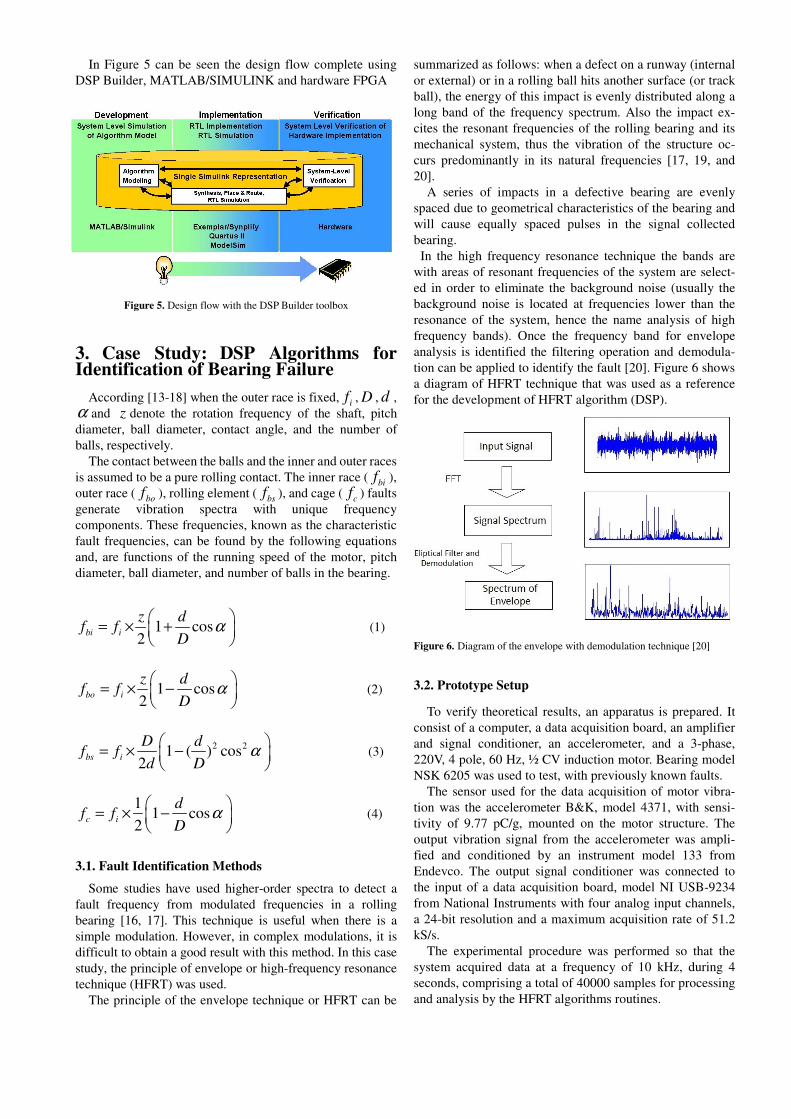
In the high frequency resonance technique the bands are
with areas of resonant frequencies of the system are select-
ed in order to eliminate the background noise (usually the
background noise is located at frequencies lower than the
resonance of the system, hence the name analysis of high
frequency bands). Once the frequency band for envelope
analysis is identified the filtering operation and demodula-
tion can be applied to identify the fault [20]. Figure 6 shows
a diagram of HFRT technique that was used as a reference
for the development of HFRT algorithm (DSP).
Figure 6. Diagram of the envelope with demodulation technique [20]
3.2. Prototype Setup
To verify theoretical results, an apparatus is prepared. It
consist of a computer, a data acquisition board, an amplifier
and signal conditioner, an accelerometer, and a 3-phase,
220V, 4 pole, 60 Hz, ½ CV induction motor. Bearing model
NSK 6205 was used to test, with previously known faults.
The sensor used for the data acquisition of motor vibra-
tion was the accelerometer B&K, model 4371, with sensi-
tivity of 9.77 pC/g, mounted on the motor structure. The
output vibration signal from the accelerometer was ampli-
fied and conditioned by an instrument model 133 from
Endevco. The output signal conditioner was connected to
the input of a data acquisition board, model NI USB-9234
from National Instruments with four analog input channels,
a 24-bit resolution and a maximum acquisition rate of 51.2
kS/s.
The experimental procedure was performed so that the
system acquired data at a frequency of 10 kHz, during 4
seconds, comprising a total of 40000 samples for processing
and analysis by the HFRT algorithms routines.
3.3. Implementation of HFRT algorithms in FPGA
Hardware
The libraries containing functional blocks of the Sim-
ulink/DSP Builder software facilitated the construction of
the basic structure of the HFRT algorithms. The FPGA
platform used is based on an Altera Cyclone II
EP2C35F672C6 device. The FPGA core board is the most
important component of the embedded system. In this case
study, an Altera DE2 board, shown in Figure 7, was used.
The relevant features on the board are (i) an SRAM with
512 KB, (ii) a 4 MB flash memory, (iii) 2 Mb block RAMs
in the FPGA, (iv) a USB port, (v) a 24-bit audio Codec to
signal of the accelerometer and (vi) a liquid-crystal display
(LCD).
After the HFRT algorithm model is verified in the
MATLAB/SIMULINK software to have no errors, the DSP
Builder software is operated to transform the model into
VHDL language. The designed model files are analyzed
and then transformed into general hardware description
language files for the selection of chip type and clock cycle.
After the hardware description files based on the regis-
ter-transfer level (RTL) are acquired, the DSP Builder soft-
ware automatically completed integration, adaptation, and
timing analysis. Finally, the files to be downloaded onto the
FPGA are generated. The working condition of the HFRT
algorithms embedded in the FPGA is consistent with the
simulation results, thus meeting the design requirements.
Figure 7. Altera DE2 board
3.4. Experimental Results
Figure 8 shows the results obtained with the HFRT algo-
rithms. Fig. 8a shows the spectrum of the vibration signal
demodulated with the identification of the five largest
amplitude peaks of the spectrum to locate the characteristic
fault frequency of the inner race. Here, the relevant
frequency component (135.01 Hz) can be easily located. Fig.
8b shows the vibration signal spectrum with the location of
the outer race characteristic fault frequency (89.50 Hz). It
is observed that the amplitude of fault frequencies can be
obtained with the DSP algorithm of the HFRT technique.
(a)
(b)
Figure 8. Identification of the inner race (a) and outer race (b) characteris-
tic fault frequency using HFRT algorithm.
5. Conclusion
This work presents a methodology for rapid prototyping
of DSP algorithms to measure mechanical vibration in
rotating machinery. Considering the current scenario of ever
increasing demand for integrated design and validation
solutions for digital systems, the use of design tools to
expedite the implementation of different architecture tools,
which allow future modifications, upgrades, and expansions
of the system on the same hardware by the end user, for
The results show that the proposed method was efficient,
facilitated design flow, and significantly reduced the time
and cost associated with prototype design. The test results of
the prototype digital system show that the specified
objectives were achieved, especially with respect to the
implementation of a DSP algorithms as FFT, Filter, and
HFRT technique in FPGA for fault identification in rotary
machines.
This method uses a high-level behavioral description of
the DSP algorithms that, for instance, allows the researcher
to replace the Fourier transform method by the Wavelet
transform method in a short time, without requiring new
hardware. The implementation can be simulated and then
deployed in an FPGA-based vibration analysis hardware
setup.
REFERENCES
[1] M. E. H. Benbouzid, A review of induction motor signature analysis as a medium for faults detection, IEEE Transactions on Industrial Electronics, Vol. 47, no. 5, pp. 984-993, Oct. 2000.
[2] A. Sadoughi, M. Ebrahimi, M. Moalem, S. Sadri, Intelligent diagnosis of broken bars in induction motors based on new features in vibration spectrum, Diagnostic for Electric Ma-chines, Power Electronics, and Drives, IEEE International Symposium, pp. 106-111, Sept. 2007.
[3] S. Nandi, H. A. Toliyat, X. Li, Condition monitoring and fault diagnosis of electrical motors – a review, IEEE Transactions on Energy Conversion, Vol. 20, no. 4, pp. 719-729, Dec. 2005.
[4] S. A. S. Al Kazzas, G.K. Singh, Experimental investigations on induction machine condition monitoring and fault diag-nosis using digital signal processing techniques, Electric Power Systems Research, no. 65, pp. 197-221, New York: Elsevier, 2003.
[5] W. Q. Lim, D. H. Zhang, J. H. Zhou, P. H. Belgi, H. L. Chan, Vibration-based fault diagnostic platform for rotary machines, IECON 2010 – 36th Annual conference on IEEE Industrial Electronics Society, pp. 1404-1409, 2010.
[6] J. J. Rangel-Magdaleno, R. J. Romero-Troncoso, L. M. Con-treras-Medina, A. Garcia-Perez, FPGA implementation of a novel algorithm for on-line bar breakage detection on induc-tion motors, IEEE International and Measurement Technol-ogy Conference, IMTC 2008, Canada, pp. 720-725, 2008.
[7] C. da Costa, M. H. Mathias, P. Ramos, P. S. Girão, A new approach for real time fault diagnosis in induction motors based on vibration measurement, Proc. Instrumentation and Measurement Technology Conference, Austin, Texas, pp. 1164-1168, May 2010.
[8] C. da Costa, M. Kashiwagi, M. H. Mathias, Development of an instrumentation system embedded on FPGA for real time measurement of mechanical vibrations in rotating machinery, In: 2012 International Symposium on Instrumentation & Measurement, Sensor Network and Automation (IMSNA), Sanya, China, pp. 60-64, 2012.
[9] A. B. Rey, F. Marin, S. De Pablo, L. C. Herrero, A method-ology for teaching the integrated simulation of power system by modeling with MATLAB/SIMULINK and controlling via a c-based algorithm, Power Electronic Education, IEEE Workshop, pp. 114-119, 2005.
[10] I. Grout, J. Ryan, T. O´Shea, Configuration and debug of field programmable gate arrays using Matlab/Simulink, Journal of Physics: Conference Series 15, pp. 244-249, 2000.
[11] M. Zengchui, W.Xin, Design and realization of real-time spectrum analysis system based on DSP builder, On: 2012 Second International Conference on Instrumentation, Meas-
urement, Computer, Communication, and Control (IMCCC), pp. 1077-1080, 2012.
[12] G. Xiong, X. Zhou, P. Ji, Implementation of the Quadrature Waveform Generator Based on DSP Builder, IEEE Computer Society, International Symposium on Intelligent Information Technology Application Workshops, IITAW´08, China, pp. 773-776, Dec. 2008.
[13] N. Tandon, A. Choudhury, A review of vibration and acoustic measurement methods for the detection of defects in rolling element bearings, Tribology International 32, pp. 469-480, New York: Elsevier, 1999.
[14] P. Maedel, Jr, Vibrations standards and test codes, shock and vibration handbook, 5th edition (Cyril Harris, editor), McGraw Hill Publishing Co., 2001.
[15] A. Lebaroud, G. Clerc, Diagnosis of induction motor faults using instantaneous frequency signature analysis, IEEE Pro-ceedings of the 2008 International Conference on Electrical Machines, ICEM 2008, 18th International Conference on, pp. 1-5, Sept. 2008.
[16] J. R. Stack, R. G. Harley, T. G. Habetler, An amplitude modulation detector for fault diagnosis in rolling element bearing, IEEE Trans. on Industrial Electronics, Vol. 51, no. 5, pp. 1097-1102, Oct. 2004.
[17] M. Xiaojian, C. Ruiqi, W. Wenying, The comparison and application of envelop demodulation in machine fault diag-nosis, Journal of DongHua University, Natural Science, no. 27, pp. 95-97, May 2005.
[18] A. Sadoughi, H. Behbahanifardl, A practical bearing fault diagnoser, Proc. International Conference on Condition Monitoring and Diagnosis, Beijing, China, pp. 151-154, Apr. 2008.
[19] F. Pan, S. R. Qin, L. Bo, Development of diagnosis system for rolling bearing faults based on virtual instrument technology, Journal of Physics: Conference Series, International Sympo-sium on Instrumentation Science and Technology, Vol. 48, pp. 467-473, 2006.
[20] R. J. G. Oliveira, V. D. Gonçalves, E. C. Medeiros, M. H. Mathias, Time-frequency analysis combining wavelets and the envelope technique for fault identification in Rotary ma-chines, Advanced Materials Research, Vol. 664, pp 901-906, 2013.


![Ece-Vii-dsp Algorithms & Architecture [10ec751]-Notes](https://static.documents.pub/doc/80x56/5695d4481a28ab9b02a0ea8e/ece-vii-dsp-algorithms-architecture-10ec751-notes.jpg)
