82 MARC0 A. CASANOVA AND JOSE E. AMARAL DE SA IBM J. RES. DEVELOP. VOL. 28 NO. 1 JANUARY 1984 Marco A. Casanova Jose E. Amaral de Sa Mapping Uninterpreted Schemes into Entity-Relationship Diagrams: Two Applications to Conceptual Schema Design A method of mapping sets of uninterpreted record or relation schemes into entity-relationship diagrams is described and then applied to two conceptual design problems. First,the method is applied to the design of relational databases. It is shown that the method can be interpreted as a normalization procedure that maps a given relational schema into a new schema that represents an entity-relationship diagram. That is, the original schema has an interpretation in terms of higher-order concepts, which helps in understanding the semantics of the database it describes. The second designproblem is related to the conversion of conventionaljile systems to the database approach. The method is used in this context to obtain a database conceptual schema from the description of the conventional system, which is one of the fundamental steps of the conversion process. 1. Introduction The design of a database can be divided into two major phases [ 1 1, conceptual or logical design and physical design. The goal of the first phase is to obtain a machine- independent, high-level description of the database, called a conceptual schema. The second phase addresses the problem of obtainingan efficient representation of the conceptual schema in terms of the access methods and file structures supported by the database management system. The result is called an internal schema. The design of the conceptual schema is a difficult task since it should reflect the semantics of the real-world applica- tion being modeled. The quality of the conceptual schema, how faithfully it represents the application, is a prerequisite for obtaining a semantically reliable database system. A system with poor performance can sometimes be tolerated, but a database system that does not reflect the real world application is useless. The conceptual schema consists of a set of logical data structures describing how data are organized, and a set of integrity constraints indicating what data values correctly reflect concrete situations. The classes of logical data struc- tures and integrity constraints allowed are determined by the data model chosen. This paperaddresses two conceptual design problems: how to define conceptual schemata for relational databases that can be interpreted in terms of higher-level concepts; and how to obtain a conceptual schema starting from the description of a conventional file system. Both problems are attacked by defining a method of assigning an interpretation in terms of the entity-relationship model [2] to a set of uninterpreted relation (or record) schemes. The method analyzes the patterns of cross refer- ences among relations to detemine whether a relation scheme represents an entity type, a relationship type, or a combina- tion of both. The entity-relationship model was chosen as the target model becauseit is accepted as a paradigm for high-level data models. As the name implies, the basic conceptsare that of an entity, which stands for an object with an independent existence, and thatof a relationship, understood as a connec- tion between entities. The interest in such a method can be better understood by discussing in more detail the two design problems addressed. 0 Copyright 1984 by International Business Machines Corporation. Copying in printed form for private use is permitted without payment of royalty provided that (I) each reproduction is done without alteration and (2) the Journal reference and IBM copyright notice are included on the first page. The title and abstract, but no other portions, of this paper may be copied or distributed royalty free without further permission by computer-based and other information-service systems. Permission to republish any other portion of this paper must be obtained from the Editor.
Transcript
82
M A R C 0 A. CASANOVA A N D JOSE E. AMARAL DE SA IBM J. RES. DEVELOP. VOL. 28 NO. 1 JANUARY 1984
Marco A. Casanova Jose E. Amaral de Sa
Mapping Uninterpreted Schemes into Entity-Relationship Diagrams: Two Applications to Conceptual Schema Design
A method of mapping sets of uninterpreted record or relation schemes into entity-relationship diagrams is described and then applied to two conceptual design problems. First, the method is applied to the design of relational databases. It is shown that the method can be interpreted as a normalization procedure that maps a given relational schema into a new schema that represents an entity-relationship diagram. That is, the original schema has an interpretation in terms of higher-order concepts, which helps in understanding the semantics of the database it describes. The second design problem is related to the conversion of conventionaljile systems to the database approach. The method is used in this context to obtain a database conceptual schema from the description of the conventional system, which is one of the fundamental steps of the conversion process.
1. Introduction The design of a database can be divided into two major phases [ 1 1, conceptual or logical design and physical design. The goal of the first phase is to obtain a machine- independent, high-level description of the database, called a conceptual schema. The second phase addresses the problem of obtaining an efficient representation of the conceptual schema in terms of the access methods and file structures supported by the database management system. The result is called an internal schema.
The design of the conceptual schema is a difficult task since it should reflect the semantics of the real-world applica- tion being modeled. The quality of the conceptual schema, how faithfully it represents the application, is a prerequisite for obtaining a semantically reliable database system. A system with poor performance can sometimes be tolerated, but a database system that does not reflect the real world application is useless.
The conceptual schema consists of a set of logical data structures describing how data are organized, and a set of integrity constraints indicating what data values correctly reflect concrete situations. The classes of logical data struc- tures and integrity constraints allowed are determined by the data model chosen.
This paper addresses two conceptual design problems: how to define conceptual schemata for relational databases that can be interpreted in terms of higher-level concepts; and how to obtain a conceptual schema starting from the description of a conventional file system.
Both problems are attacked by defining a method of assigning an interpretation in terms of the entity-relationship model [2] to a set of uninterpreted relation (or record) schemes. The method analyzes the patterns of cross refer- ences among relations to detemine whether a relation scheme represents an entity type, a relationship type, or a combina- tion of both.
The entity-relationship model was chosen as the target model because it is accepted as a paradigm for high-level data models. As the name implies, the basic concepts are that of an entity, which stands for an object with an independent existence, and that of a relationship, understood as a connec- tion between entities.
The interest in such a method can be better understood by discussing in more detail the two design problems addressed.
0 Copyright 1984 by International Business Machines Corporation. Copying in printed form for private use is permitted without payment of royalty provided that ( I ) each reproduction is done without alteration and (2) the Journal reference and IBM copyright notice are included on the first page. The title and abstract, but no other portions, of this paper may be copied or distributed royalty free without further permission by computer-based and other information-service systems. Permission to republish any other portion of this paper must be obtained from the Editor.
Consider first the design of relational databases. The relational model of data, as originally conceived by Codd [3], adopted relations (or tables) as the ony logical data struc- tures, leaving practically all semantics to be expressed by integrity constraints. Having relations as the sole data struc- ture makes the model conceptually very simple. However, since relations are semantically neutral, large relational conceptual schemata can be difficult to understand. To remedy this difficulty, an extended relational model, with more semantic constructs, was proposed later by Codd [4].
The method discussed in this paper offers an alternative solution by showing how to map relational schemata into entity-relationship schemata. When the mapping is a t all possible, the relational schema is said to be in entity- relationship normal form (ERNF). Besides being based on the idea of a mapping, ERNF differs from previous normal forms [5-71 since it depends on an analysis of certain constraints on pairs of relations called inclusion dependencies [8], whereas the five well-known normal forms are based on constraints on individual relations.
Consider now the conversion of conventional file systems to the database approach. It is claimed that the first step of such a process should be the design of a high-level, integrated conceptual schema and that the design should be based on the description of the original system.
The method helps in this case because the conceptual schema can be designed in two steps. First, a loosely integrated relational schema that is closely correlated with the conventional file system is defined. At this stage, prob- lems such as domain definitions are taken care of. Then the method is applied to integrate and normalize the relational schema and, finally, map it into a high-level entity-relation- ship schema.
It should be clear that the method helps just one step of the conversion process. It covers neither the complete design of the database nor the conversion of application programs. It also leaves untouched the problem of initializing the data- base operation. In particular, it does not cover physical database design, which might be based on an analysis of the file design, since the latter usually reflects performance considerations.
A methodology close to that described in this paper was developed in [9] for obtaining entity-relationship views of a relational conceptual schema. The CHARADE project [ 101 can also be compared to the method described, a t least in purpose. The conversion of conventional file systems has not received much attention in the literature. In fact, no major reference exists as far as we know, except in connection with the problem of extracting data from existing files to load the
database [ l l , Chap. 10.11. The design of relational data- bases based on normalization theory has, on the contrary, a vast literature (good surveys can be found in [3,11- 14]), but the notion of a normal form defined via a mapping to entity-relationship schemata and using inclusion dependen- cies has not been considered before.
This paper is organized as follows. Section 2 contains basic concepts and introduces the notation used. Section 3 illus- trates the method proposed with an example. Section 4 describes a method of combining sets of relation schemes. Section 5 presents an algorithm that synthesizes entity- relationship schemes from a set of uninterpreted relation schemes and inclusion dependencies. Section 6 discusses two applications of the algorithm described in Section 5, one in connection with the design of relational databases and another related to the conversion of conventional file systems to the database approach. Finally, Section 7 contains conclu- sions and directions for future research.
2. Basic concepts and notation In this section, we first give a brief survey of the entity- relationship model, which may be skipped on a first reading. We then present the concepts and notation of the relational model used throughout the paper.
The entity-relationship model The entity-relationship model provides a high-level tool to describe databases. As the name implies, it is centered on two informal concepts: entity and relationship. An entity is vaguely defined as any object with an independent existence, such as employee or department. A class of entities of the same kind is called an entity set.
A relationship is a tuple of entities and represents an association between those entities. Given a list E , , ..., E,, of entity sets, not necessarily distinct, an n-ary relationship set is a subset R of the Cartesian product E , x ... x E,,. R is said to be the total on Ei iff every entity in Ei participates in some relationship in R. A binary relationship set R between E , and E, may also be classified as n - I , 1-1, and n-m, if R is, respectively, a many-to-one function, a one-to-one function, or a many-to-many relation between E, and E , . For example, a binary, n-1 relationship set, called WORKS, may be defined between entity sets EMPLOYEES and DEPART- MENTS indicating, for each employee, the unique depart- ment he works in. Higher-order relationship sets, which involve other relationship sets in their definition, are also considered in this paper.
Entities and relationships may have properties, called attributes. More precisely, an attribute of an entity or relationship set S is a function from S into some domain D. Examples are employees’ names and salaries, and the posi- 83
M A R C 0 A. CASANOVA AND JOSE E. AMARAL DE SA IBM J. RES. DEVELOP. VOL. 28 NO. I JANUARY 1984
84
M A R C 0 A. C
tion an employee has in a department, which is an attribute of the relationship WORKS.
A set K of attributes whose values uniquely identify each entity in an entity set E is called a key of E . Keys for relationship sets are similarly defined. Usually, the key of a relationship set is the concatenation of the keys of the entity sets involved.
Sometimes entities in a set E cannot be identified through their own attributes, but only through a relationship set R to other entity sets E , , ..., E,,. Then, E is said to be a weak entity set, R is said to be an identifying relationship set, and E , , ..., En are said to be identifying entity sets. (This is not standard terminology.) In this paper, only total, binary, n-1 identifying relationship sets are used such that each weak entity is necessarily related to exactly one identifying entity. The familiar example is that of an entity set EMPLOYEES, a weak entity set DEPENDENTS, and a binary, n-1 iden- tifying relationship set DEPENDENT-OF between DE- P E N D E N T S (on the “n” and “total” side) and EMPLOYEES. Intuitively, a dependent x is identified by his name, say, and by the fact that x is related to some (unique) employee y .
A conceptual schema in the entity-relationship model is usually presented as an entity-relationship diagram, where
0 Rectangles represent entity sets. Diamonds represent relationship sets. If R is a relationship set between entity or relationship setsS,, ..., Sn, then there is an edge between the diamond representing R and the figure (rectangle or diamond) representing Si, i = 1 , ..., n. The edge may be labeled with i , if S, is equal to S,, for some i and j in [ 1 , n] . Otherwise, the order of the sets in the list is irrelevant.
0 Ovals represent attributes. If A is an attribute of an entity or relationship set S, then there is an edge between the oval representing A and the figure representing S. Double rectangles represent weak entity sets.
An example of an entity-relationship diagram appears in Section 3.
Finally, we call a statement of the form E [ A , , ..., An] an entity type iff E is the name of an entity set S and A,, ..., An are the names of the attributes of S. Likewise, R [ N , , ..., Nm; A , , ..., A n ] is a relationship type iff R is the name of a relationship set S, N , , ..., N , are the names of the entity or relationship sets related by S, and A , , ..., An are the names of the attributes of S.
Concepts from the relational model This section introduces several concepts pertaining to the relational model of data that are used throughout the paper.
A relation scheme is a pair ( R , U ) , where R is the name of the relation scheme and U is a finite set {A, , ..., A,,] of attributes of R. The notation R [ A , , ..., A,] is used for ( R , U ) .
A database scheme is a finite set DS of relation schemes. A database state or simply a state of DS is a function u
associating, to each relation scheme R in DS with n attri- butes, n > 0, an n-ary relation r = u(R). If t is in v(R) and X is a sequence (or a set) of attributes of R , then t [ X ] denotes the projection o f t on the attributes in X .
A key of a relation scheme R in DS is a set K of distinct attributes of R . Given a state u of DS, u is said to satisfy K iff for any t and t’ in u(R), if t [ K ] = t ’ [ K ] , then t = t‘. Note that keys need not be minimal; that is, K is a key even if there is a strict subset of K which is also a key.
If R and S are two relation schemes in DS and X and Yare sequences of attributes of R and S, respectively, such that X and Y have the same length, then the sentence R [ X ] C S [ Y ] is called an inclusion dependency [ S I . Given a state u of DS, u is said to satisfy R [ X ] C S [ Y ] iff for any tuple t in u(R) there is a tuple u in u(S) such that t [ X ] = u [ Y ] .
Relational expressions over DS are also used with the standard definition [ 131. Given a state u of DS, u can be extended to expressions over DS in the usual way; the value of an expression E is denoted by u(E).
An integrity constraint is a sentence over a set of relation schemes. Of the many families of relational integrity con- straints studied in the literature [12, 131, only keys and inclusion dependencies are used in this paper.
A relational schema is a pair RS = (DS, CS) , where DS is a database schema and CS is a set of integrity constraints over DS. A database state of RS is any database state u of DS; if u satisfies all constraints in CS, then u is said to be a consistent database state of RS.
Finally, some concepts that are not standard, but which play a central role in later sections, are introduced.
Let R [ K ] C S [ L ] be an inclusion dependency such that L is a key of S. Then, R [ K ] C S [ L ] is called a reference and R is said to reference S via K and L; moreover, K is said to be an out-key of R, and L is said to be an in-key of S. Out-keys are called foreign keys in [ 141, but the name “out-key’’ is preferred in this case to match the notion of in-keys. R is said to reference S iff there are K and L such that R references S via K and L. When the reference involves relation schemes taken from a set of relation schemes DS, the reference is said to be over DS.
‘ASANOVA AND JOSE E. AMARAL DE SA IBM J. RES. DEVELOP. \ IOL. 28 NO. I J ANUARY 1 984
Not all sets of references are considered, though, since some sets may lead to ambiguities. A set SIGMA of refer- ences over a set of relation schemes DS is said to be well-formed iff, for any two relation schemes R and S of DS, if R[K] S[L] and R[K'] C S[L'] are in SIGMA then K = K' and L = L'. Thus, if SIGMA is well-formed, there is no ambiguity when we say that R references S, since R does not reference S in more than one way.
This concludes the list of basic definitions and notation used in the next sections.
3. Mapping relation schemes into entity-relation- ship concepts: an example This section informally presents, with the help of an example, a method of mapping a relational schema into an entity relationship schema.
Consider a relational schema with the following set of relation schemes (call it DS):
(1) DEPT[DNAME] key:DNAME
(2) DEPT-MGR[DNAME,MGR] key:DNAME
key: SSN
key:NO
key: N 0 , N A M E
key:DOCNM
(3) CLERK[SSN,NAME,AGE]
(4) EMP[NO,POSITION,DNAME]
( 5 ) DEPENDENT[NO,NAME,DOCNM]
( 6 ) DOCTOR[DOCNM,SPECIALITY]
Without further analysis, nothing can be inferred. In particular, the fact should be stressed that DNAME is an attribute of DEPT and DEPT-MGR is not a sufficient indication that any association exists between DEPT and DEPT-MGR. At most, one may admit that these attributes would have the same domain if a careful naming convention were followed. (Certain view integration methodologies- for example [ 15]-would identify the two occurrences of DNAME without further consideration, which is contrary to our view [ 161 .)
Assume now that the set of integrity constraints of the relational schema logically implies the following set of references (call it SIGMA):
(7) DEPT-MGR[DNAME] C DEPT[DNAME] (8) DEPT-MGR[MGR] C EMP[NO] (9) CLERK[SSN] C EMP[NO] (10) EMP[NO] C CLERK[SSN] (1 1) EMP[DNAME] C DEPT[DNAME] (12) DEPENDENT[NO] C EMP[NO] (13) DEPENDENT[DOCNM] C DOCTOR[DOCNM]
Then certain inferences can be drawn. Consider DOC- TOR first. This relation scheme does not reference any other relation scheme, but it is referenced by other relation schemes. Thus, tuples may be freely inserted into, but not deleted from, the relation associated with DOCTOR, depending on how the references to DOCTOR are treated. In general, a relation scheme R[A,, ..., A,,] of the relational schema represents an entity type (in view of the references contained in the set of integrity constraints of the relational schema) when Condition 1 is satisfied:
Condition 1: R does not reference other relation schemes.
Similar observations also apply to DEPT. However, since DEPT has just one attribute, it may also be interpreted as representing a domain definition. In general, the choice must take into account at least the following facts:
a. If a relation scheme R is taken as representing a domain, entries cannot be inserted or deleted from the relation denoted by R; however, the entity-relationship schema will be somewhat simpler since it will contain one less entity type. R will usually have just one attribute when it represents a domain, although multicolumn domains are not impossible. The cardinality of the relation denoted by R will also tend to be small.
b. If, on the other hand, R is taken as representing an entity type, the relation denoted by R can be modified; however, the entity-relationship schema will have one more entity type and, hence, will be more complex.
Another consequence is that the first choice leads to fewer relationship types in the entity-relationship schema than the second one.
Consider now DEPT-MGR. It references more than one relation scheme and the set of out-keys is a key. One may then consider that DEPT-MGR defines a relationship type. In general, a relation scheme R[A,, ..., A,,] defines a rela- tionship type iff Condition 2 holds, where
Condition 2: R references more than one relation scheme and the union of all out-keys of R is a key of R.
Note that R may be referenced by other relation schemes, since higher-order relationships are allowed in the version of the entity-relationship adopted in this paper.
Consider now EMP and CLERK. These two relation schemes reference each other and, moreover, the references involve only keys. More precisely, the constraints of the relational schema imply the sentences EMP[NO] C CLERK[SSN] and CLERK[SSN] C EMP[NO] and, moreover, N O and SSN are keys of EMP and CLERK, respectively. So, for any consistent state u, each element in 85
IBM J . RES. DEVELOP. VOL. 28 NO. I JANUARY 1984 M A R C 0 A. CASANOVA AND JOSE E. AMARAL DE SA
86
u(EMP[NO]) is associated with exactly one tuple in u(EMP) and exactly one tuple in u(CLERK), and vice versa. Thus, one may collapse EMP and CLERK into one relation scheme:
(14) EMPLOYEE[NO,NAME,AGE, POSITION,DNAME] key: NO
The references in (7) to (1 3) have to be modified adequately by replacing EMP and CLERK by EMPLOYEE as follows:
(15) DEPT-MGR[DNAME] C DEPT[DNAME] (16) DEPT-MGR[MGR] C EMPLOYEE[NO] (17) EMPLOYEE[DNAME] C DEPT[DNAME] (18) DEPENDENT[NO] C EMPLOYEE[NO] (19) DEPENDENT[DOCNM] C DOCTOR[DOCNM]
Now, EMPLOYEE cannot be considered to represent just an entity type since Condition 1 is not satisfied. Thus, it is proposed to break EMPLOYEE into two relation schemes:
(20) EMPL[NO,NAME,AGE,POSITION] key: NO (21) EMPL-DEPT[NO,DNAME] key:NO
and to modify SIGMA accordingly:
(22) DEPT-MGR[DNAME] C DEPT[DNAME] (23) DEPT-MGR[MGR] C EMPL[NO] (24) EMPL DEPT[NO] C EMPL[NO] (25) EMPL-DEPT[DNAME] C DEPT[DNAME] (26) DEPENDENT[NO] C EMPL[NO] (27) DEPENDENT[DOCNM] C DOCTOR[DOCNM]
Now, EMPL satisfies Condition 1 and, hence, it may be considered to represent an entity type. As for EMPL-DEPT, it defines a relationship type, just like DEPT-MGR.
Finally, since EMPL and EMPL-DEPT were obtained by splitting EMPLOYEE, one may conclude that a single relation scheme, EMPLOYEE in this case, may originate an entity type and a relationship type.
The analysis of DEPENDENT is also interesting. DEPENDENT references two other relation schemes, but the union of its out-keys does not contain a key. Hence, DEPENDENT does not satisfy Condition 2. It is then proposed to break DEPENDENT into two relation schemes:
(30) DEP[NO] C EMPL[NO] (31) DEPDOC[NO,NAME] C DEP[NO,NAME] (32) DEPDOC[DOCNM] C DOCTOR[DOCNM]
MARC0 A. CASANOVA AND JOSE E. AMARAL DE SA
Now DEPDOC represents a relationship type since it satisfies Condition 2. As for DEP, it will be considered to represent a weak entity type subordinated to EMPL, together with its identifying relationship type. In general, a relation scheme R [ A , , ..., A,] is considered to represent a weak entity type, together with its identifying relationship type, when Condition 3 is met:
Condition 3: R references just one relation scheme and the out-key of R intersects every key of R.
Thus, when all attributes in the out-key are dropped, R is left with no keys, i.e., tuples in R lose their identity.
The final result of the discussion is a set of relation schemes (call it DS’):
(32) DEPT[DNAME] key:DNAME
key:DOCNM
key: NO
key: N0,NAME
key:DNAME
key: N0,DNAME
key: N0,NAME
(33) DOCTOR[DOCNM,SPECIALITY]
(34) EMPL[NO,NAME,AGE,POSITION]
(35) DEP[NO,NAME]
(36) DEPT-MGR[DNAME,MGR]
(37) EMPL-DEPT[NO,DNAME]
(38) DEPDOC[NO,NAME,DOCNM]
and a set of references (call it SIGMA’):
(39) DEP[NO] C EMPL[NO] (40) DEPT-MGR[MGR]C EMPL[NO] (41) DEPT-MGR[DNAME] C DEPT[DNAME] (42) EMPL-DEPT[NO] C EMPL[NO] (43) EMPL-DEPT[DNAME] C DEPT[DNAME] (44) DEPDOC[NO,NAME)] C DEP[NO,NAME] (45) DEPDOC[DOCNM] C DOCTOR[DOCNM]
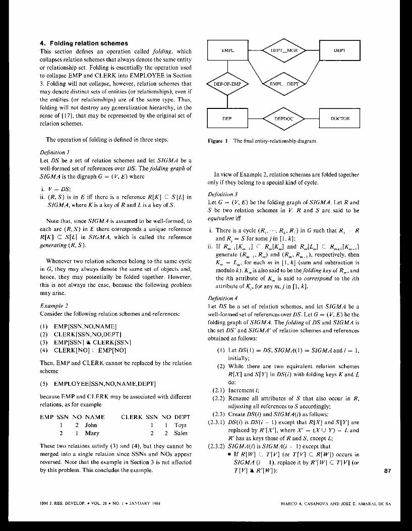
Each relation scheme in DS‘ represents an entity type, a relationship type, or a weak entity type. The corresponding entity-relationship diagram is shown in Fig. 1. Each object in the diagram has the same name and the same attributes as the corresponding relation scheme. The only exception is DEP, which is mapped into a weak entity type with the same name and attributes, except those in the out-key of DEP, and a binary relationship type, DEP-OF-EMP, which acts as the identifying relationship type. For the sake of simplicity, attributes are omitted in the figure.
This concludes the analysis of the running example. Sec- tions 4 and 5 bring precision to the discussion in this section.
IBM J. RES. DEVELOP. VOL. 28 NO. I JANUARY 1984
4. Folding relation schemes This section defines an operation called folding, which collapses relation schemes that always denote the same entity or relationship set. Folding is essentially the operation used to collapse EMP and CLERK into EMPLOYEE in Section 3. Folding will not collapse, however, relation schemes that may denote distinct sets of entities (or relationships), even if the entities (or relationships) are of the same type. Thus, folding will not destroy any generalization hierarchy, in the sense of [ 171, that may be represented by the original set of relation schemes.
The operation of folding is defined in three steps:
Dejinition I Let DS be a set of relation schemes and let SIGMA be a well-formed set of references over DS. Thefolding graph of SIGMA is the digraph G = (V, E ) where
i. V = DS; ii. ( R , S) is in E iff there is a reference R [ K ] C S [ L ] in
SIGMA, where K is a key of R and L is a key of S.
Note that, since SIGMA is assumed to be well-formed, to each arc (R, S) in E there corresponds a unique reference R [ K ] C S[L] in SIGMA, which is called the reference generating (R, S).
Whenever two relation schemes belong to the same cycle in G , they may always denote the same set of objects and, hence, they may potentially be folded together. However, this is not always the case, because the following problem may arise.
Example 2 Consider the following relation schemes and references:
Then, EMP and CLERK cannot be replaced by the relation scheme
( 5 ) EMPLOYEE[SSN,NO,NAME,DEPT]
because EMP and CLERK may be associated with different relations, as for example
EMP SSN NO NAME CLERK SSN NO DEPT 1 2 John 1 1 Toys 2 1 Mary 2 2 Sales
These two relations satisfy (3) and (4), but they cannot be merged into a single relation since SSNs and NOS appear reversed. Note that the example in Section 3 is not affected by this problem. This concludes the example.
IBM J. RES. DEVELOP. VOL. 28 NO. I JANUARY 1984
I
DEP DOCTOR
Figure 1 The final entity-relationship diagram.
In view of Example 2, relation schemes are folded together only if they belong to a special kind of cycle.
Dejinition 3 Let G = (V, E ) be the folding graph of SIGMA. Let R and S be two relation schemes in V. R and S are said to be equivalent i f f
i. There is a cycle (Rl, ..., R,, R , ) in G such that R , = R and R, = S for somej in [ 1, k];
generate (R, - , , R , ) and (Rm, R , , , ) , respectively, then K,,, = L,, for each m in [ 1, k] (sum and subtraction is modulo k). K,,, is also said to be thefolding key of Rm, and the ith attribute of K , is said to correspond to the ith attribute of K,, for any m , j in [ l , k] .
ii. If R,- , [K,- , l c R,,,[K,,,I and R,,,[L,,,I c Rm+IIKm+,l
Dejinition 4 Let DS be a set of relation schemes, and let SIGMA be a well-formed set of references over DS. Let G = (V, E ) be the folding graph of SIGMA. The folding of D S and SIGMA is the set DS’ and SIGMA’ of relation schemes and references obtained as follows:
( 1 ) LetDS(1) = D S , S I C M A ( l ) = S I G M A a n d i = 1, initially;
(2) While there are two equivalent relation schemes R [ X ] and S[Y] in DS(i) with folding keys K and L do:
(2.1) Increment i; (2.2) Rename all attributes of S that also occur in R ,
adjusting all references to S accordingly; (2.3) Create DS(i) and SIGMA(i) as follows:
(2.3.1) DS(i) is DS(i ~ 1) except that R [ X ] and S[Y] are replaced by R ’ [ X ’ ] , where X’ = ( X U Y ) - L and R‘ has as keys those of R and S, except L;
If R [ W ] C T [ VI (or T [ V ] C R [ W ] ) occurs in SIGMA (i - I ) , replace it by R’[ W ] C T [ VI (or
(2.3.2) SIGMA(i) is SIGMA(i - 1) except that
T[VI R ’ [ W I ) ; 87
MARC0 A. CASANOVA AND JOSE E. AMARAL DE SA
0 If S[W] C T [ VI (or T [ VI C S [ W ] ) occurs in SIGMA ( i - I ) , replace it by R’[ W‘] C T [ VI (or T[V] C R’[W’]), where W’ is W with each attribute in L replaced by the corresponding attri- bute of K
(3) DS‘ = DS(i) and SIGMA’ = SIGMA(i) , when the loop terminates.
Example 5 Consider again part of the original set of relation schemes and references of Section 3:
(1) CLERK[SSN,NAME,AGE] key: SSN
key:NO
key: N0,NAME
(2) EMP[NO,POSITION,DNAME]
(3) DEPENDENT[NO,NAME,DOCNM]
(4) CLERK[SSN] C EMP[NO] (5) EMP[NO] C CLERK[SSN] (6) DEPENDENT[NO] C EMP[NO]
The corresponding folding graph is G = (V, E ) , where
v = {CLERK,EMP,DEPENDENT} E = {(CLERK,EMP),(EMP,CLERK)}
The folding of these relation schemes and references then collapses CLERK and EMP into a single relation scheme, producing
( I ) CLERK[SSN,NAME,AGE,POSITION,DNAME] key: SSN
key: N 0 , N A M E (2) DEPENDENT[NO,NAME,DOCNM]
(3) DEPENDENT[NO] C CLERK’[SSN]
This concludes the example.
Folding has an important property that essentially says that no information is lost during the operation. This prop- erty is defined in general as follows:
Dejinition 6 Let R S = (DS, CS) and RS‘ = (DS’, CS’) be two relational schemata. RS’ is said to represent RS iff, for each relation scheme R in DS, there is an expression E over DS’ such that, for every consistent state v’ of RS‘, the function v from DS into relations constructed by taking v(R) = v’ (E) is a consistent state of RS.
Proposition 7 Let DS’ and SIGMA’ be the folding of DS and SIGMA. Then (DS’, SIGMA’) represents (DS, SIGMA), and vice versa.
Sketch of proof It can be proved by induction on i that (DS(i) , SIGMA(i)) represents (DS, SIGMA) and vice versa. 88
MARC0 A. CASANOVA P rND JOSE E. A ,MARAL DE SA
Basis i = 1. There is nothing to prove, since DS( 1) = DS and SIGMA( 1) = SIGMA.
Induction step Let i > 1 and suppose that (DS(i - I ) , SZGMA(i - 1)) represents (DS, SIGMA). Let DS(i) and SIGMA(i) be the result of the ith step of the algorithm in Definition 4. Then it can be proved that, since R and S are equivalent, step 3 of the algorithm is such that (DS(i) , SIG- M A ( i ) ) represents (DS(i - l ) , SIGMA(i - 1)) and vice versa. But the property of representation is transitive. Hence, (DS(i) , SIGMA(i)) represents (DS, SIGMA). Therefore, one may conclude that ( D S ‘ , S I G M A ’ ) represents (DS, SIGMA) and vice versa, if the former pair is the folding of the latter pair.
This concludes the discussion of folding.
5. An algorithm mapping a family of relational schemata into entity-relationship schemata In this section, the remarks made in Section 3 are trans- formed into an algorithm mapping a set of relation schemes and a set of references into an entity-relationship schema.
Let us begin with a comprehensive definition of what it means for a relation scheme to define an entity-relationship object in the presence of a set of references. These concepts were already illustrated in Section 3.
Dejinition 8 Let DS be a set of relation schemes and SIGMA be a well-formed set of references. Let R be a relation scheme in DS.
a. R defines an entity type in the presence of SIGMA iff SIGMA contains no reference of the form R[K] C S [ L ] , for any S in DS.
b. R dejines a weak entity type in the presence of SIGMA iff SIGMA contains a single reference of the form R[K] C S [ L ] , for some S in DS, and K intersects every key of R. R is also said to be subordinated to S in the presence of SIGMA.
c. R dejines a relationship type in the presence of SIGMA iff SIGMA contains a set of references of the form R[K,] C S , [L,], ..., R[K,] C S,[L,] such that K , U ... U K,,, is a key of R. R is also said to relate the relation schemes it references.
d. R deJines an ER-object iff R defines either an entity type, a weak entity type, or a relationship type.
e. DS and SIGMA dejine an entity-relationship schema (or, simply, an ER-schema) iff each relation scheme in DS defines an ER-object.
The definitions in (a), (b), and (c) are justified by comparing the behavior of the relation denoted by R with the behavior of entity sets, weak entity sets, and relationship sets.
IBM J. RES. DEVELOP. VOL. 28 NO. 1 JANUARY 1984
Let v be a state of DS satisfying SIGMA. Thus, if R satisfies (a), then the existence of tuples in v(R) is not constrained by the existence of tuples in any other relation, since R refer- ences no relation scheme. Now, if R satisfies (b), then if K is deleted from the attribute set of R, no key of R is left, i.e., tuples in v(R) lose their identity. It should be said at this point that, if R satisfies (b), then R actually represents the weak entity set together with its identifying relationship set. Finally, if R satisfies (c), each tuple in v(R) uniquely determines a tuple in v(RiI) x ... x v(Rim), that is, a rela- tionship between entities in v ( R , , ) , ..., v(R,,), where R,, ..., Rim is the set of all relation schemes referenced by R. Indeed, since the union of all out-keys of R is a key of R, no two tuples in v(R) determine the same tuple in v(RiI) X ... X v(Rim).
With the help of these definitions, the conceptual schema design problem addressed in this section can be posed as follows.
Problem PI Given a set DS of relation schemes and a well-formed set S I G M A of references over DS, construct a set DS’ of relation schemes and a set SIGMA’ of references over DS’ such that i) DS’ and SIGMA‘ define an ER-schema; ii) (DS, S I G M A ) represents (DS’, SIGMA‘); iii) (DS’, S I G M A ’ ) represents (DS, S I G M A ) .
Condition (i) guarantees that an entity-relationship schema can be associated with DS’ and SIGMA’, which was the primary goal of this section. The other two conditions guarantee that the relational schemas RS = (DS, S I G M A ) and RS‘ = (DS‘, SIGMA’) are equivalent in the sense that each consistent state of RS can be mapped by relational algebra expressions into a consistent state of RS‘, and vice versa. This notion of equivalence correponds to that hinted at in [ 181, but differs from definitions of equivalence based on the universal relation assumption sometimes adopted [ 5 , 19, 201.
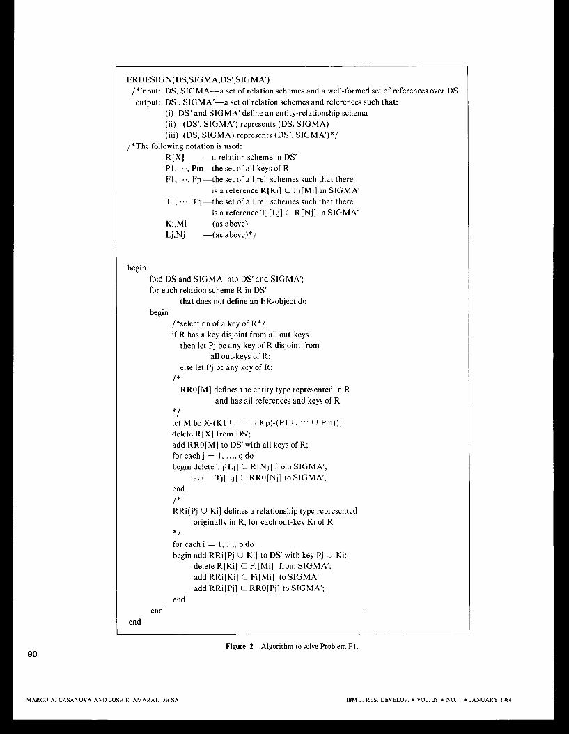
Figure 2 describes an algorithm that solves Problem P1.
The algorithm in Fig. 2 works as follows. The initial folding operation is used to collapse relation schemes that represent the same ER-object, thus avoiding trivial violations of the conditions expressed in Definition 8. After folding, each relation scheme R is inspected to determine if it defines an ER-object. The algorithm is in fact an optimized form of the following case analysis:
Case I : R references no relation scheme. The R trivially defines an entity type and nothing is done.
Case 2: R references exactly one relation scheme.
Case 2.1: Every key intersects the out-key. Then R defines a weak entity type and nothing is done.
Case 2.2: Some key of R is disjoint from the out-key of R. Then R is replaced by RR, and RR,, which define the entity type and the rela- tionship type originally represented by R, respectively.
Case 3: R references more than one relationship schema. Case 3.1: The union of out-keys of R is a key of R.
Then R defines a relationship type and nothing is done.
Case 3.2: The union of out-keys of R is not a key of R. R is replaced by RR, and RR,, ..., RR,, which define the entity type and the binary relationship types originally represented by R, respectively. (The binary relationships are equivalent to the original relationship represented by R.)
Note that RR, and R have the same set of attributes when ( K , U . . . U K,) C (P, U ... U P,). The algorithm in this case works basically by reorganizing the references. As such, RR,, ..., RRP are not redundant since tuples can be freely inserted in RR,, but not in RR,.
The way Case 3.2 is treated may be better understood by means of an example.
Example 9 Consider the following relation schemes and references:
Then, SUPPLIER and PROJECT define entity types, but SPJ defines no ER-object since it has two out-keys, S# and J#, which do not cover the key S#,P#. The solution adopted in the algorithm amounts to replacing (3) by
(6) SPJO[S#,P#,QTYl key: S#,P# (9) SPJl [S#,P#l key: S#,P# ( 1 0) SPJ2[S#,P#,J#l key: S#,P#,J# (1 1) SPJl [S#,P#] C SPJO[S#,P#] (12) SPJl[S#] C SUPPLIER[S#] (13) SPJ2[S#,P#] C SPJO[S#,P#] (14) SPJ2[J#] C PROJECT[J#]
This solution amounts to recognizing a new entity type represented by SPJO (meaning “order,” say), with key S#,P# and attributes S#,P# and QTY. This is accompanied by two new relationship types represented by SPJl and SPJ2 (mean- ing “order-supplier” and “order-project,’’ respectively).
M A R C 0 A. C ASANOVA P L N D JOSE E. AMARAL I
89
>E SA IBM J. RES. DEVELOP. VOL. 28 . NO. I JANUARY 1984
ERDESICN(DS,SIGMA;DS‘,SIGMA’) /*input: DS, SIGMA-a set of relation schemes and a well-formed set of references over DS output: DS’, SIGMA’-a set of relation schemes and references such that:
(i) DS’ and SIGMA’ define an entity-relationship schema (ii) (DS’, SIGMA’) represents (DS, SIGMA) (iii) (DS, SIGMA) represents (DS’, SIGMA‘)*/
R[X] -a relation scheme in DS’ PI , . . ., Pm-the set of all keys of R FI, . . ., Fp -the set of all rel. schemes such that there
TI, . . ., Tq -the set of all rel. schemes such that there
Ki,Mi -(as above) Lj,Nj -(as above)*/
/*The following notation is used:
is a reference R[Ki] C Fi[Mi] in SIGMA’
is a reference Tj[Lj] C R[Nj] in SIGMA’
begin fold DS and SIGMA into DS’ and SIGMA’; for each relation scheme R in DS‘
that does not define an ER-object do begin
/*selection of a key of R*/ i f R has a key disjoint from all out-keys
then let Pj be any key of R disjoint from all out-keys of R;
else let Pj be any key of R;
RRO[ MI defines the entity type represented in R / *
and has all references and keys of R
let M be X-(Kl U ... U Kp)-(PI U .‘. U Pm)); delete R[X] from DS’; add RRO[M] to DS’ with all keys of R; for each j = 1 , . . ., q do begin delete Tj[Lj] C R[Nj] from SIGMA’;
add Tj[Lj] C RRO[Nj] to SIGMA‘;
* /
end
/ * RRi[Pj U Ki] defines a relationship type represented
originally in R, for each out-key Ki of R *I for each i = 1, . . ., p do begin add RRi[Pj U Ki] to DS’ with key Pj U Ki;
delete R[Ki] C Fi[Mi] from SIGMA’; add RRi[Ki] C Fi[Mi] to SIGMA’; add RRi[Pj] C RRO[Pj] to SIGMA’;
end end
end
Figure 2 Algorithm to solve Problem PI. 90
MARC0 A. CASANOVA AND JOSE E. AMARAL DE SA IBM J . RES. DEVELOP. VOL. 28 NO. 1 JANUARY 1984
A second and equally viable treatment of Case 3.2 would be to add a new relation scheme and a new reference as follows:
( 6 ) PART(P#) key: P# (7) SPJ[P#] C PART[P#]
This solution fixes the problem by adding the entity type (defined by PART) that was missing in the relationship type between suppliers-parts-projects (defined now by SPJ), so to speak.
The algorithm can be modified to opt between the two alternatives, perhaps prompted by the designer, if additional information is available to guide the choice.
The correctness of the algorithm in Fig. 2 is stated in the following theorem.
Theorem 10 The algorithm in Fig. 2 correctly solves Problem P1.
Proof It has to be proved that, given a set DS of relation schemes and a well-formed set SIGMA of references over DS, the algorithm outputs a set DS' of relation schemes and a set SIGMA' of references over DS' such that
A. DS' and SIGMA' define an ER-schema; B. (DS', SIGMA') represents (DS, SIGMA); C. (DS, SIGMA) represents (OS', SIGMA')
Consider (A) first. After folding, the loop must terminate because DS' initially contains a finite number of relation schemes satisfying the loop condition and, at each iteration, each such relation scheme is replaced by other relation schemes not satisfying the loop conditions. Indeed, let R be the relation scheme selected at some loop iteration. There are three cases to consider:
Case 1: R references no relation scheme. Then, R defines an entity type and could not have been selected for the loop iteration.
Case 2.1: Every key intersects the out-key. Case 2: R references exactly one relation scheme.
Then, R defines a weak entity type and could not have been selected for the loop iteration.
Case 2.2: Some key of R is disjoint from the out-key of R. Then, R is replaced by RR, and R R , , which define an entity type and a rela- tionship type, respectively.
Case 3: R references more than one relationship schema. Case 3.1: The set of out-keys of R is a key of R.
Then, R defines a relationship type and could not have been selected for the loop iteration.
Case 3.2: The set of out-keys of R is not a key of R. R is replaced by RR, and RR, , ..., RRp, which define an entity type and binary relationship types, respectively.
Therefore, the loop terminates and, moreover, the loop condition must be false in the final state. So the loop terminates in a state such that each relation scheme in DS' defines an ER-object, from which assertion (A) is immedi- ately established. This concludes this part of the proof.
To prove (B) and (C), it suffices to observe that, by Proposition 7, (B) and (C) hold after the folding of DS and SZGMA and that (B) and (C) are preserved each time the algorithm replaces a relation scheme R by other relation schemes, since R is the natural join of RR,, . . ., RRp and RR, contains all keys of R and, in turn, RR, is obtained from R by projection. This concludes the proof.
To conclude, one can easily convert the output of the algorithm in Fig. 2 into an entity-relationship schema by mapping each relation scheme R into the ER-object E that it defines; the set of attributes and keys of E is equal to the set of attributes and keys of R, respectively. The only exception is when R defines a weak entity type. Let K be the out-key of R and S be the relation scheme R is subordinated to. In this case, R is mapped into a weak entity type W with the same name and attributes as R, except those in K , and into a binary relationship type (the identifying relationship type of W ) , with no attributes, between W and the ER-object defined by S.
6. Two applications of the method This section discusses two applications of the algorithm described in Section 5 , one in connection with the design of relational databases and another related to the conversion of conventional file systems to the database approach.
An application to the design of relational databases The relational model of data, as originally conceived by Codd [3] adopted relations (or tables) as the only logical data structure, leaving practically all semantics to be expressed by integrity constraints. However, since relations are semanti- cally neutral, large relational conceptual schemes tend to be difficult to understand. One possible strategy to remedy this difficulty would be to extend the relational model with more semantic constructs. A solution along these lines was pro- posed in [4]. However, adding more constructs has an adverse effect on the data definition and data manipulation languages of the model, since they become more complex. In addition, several database management systems, based on the original relational model, are already .in use.
~
91
M A R C 0 A. CASANOVA AND JOSE E. AMARAL DE SA
92
A second possible solution would be to use a conceptual design method that leads to relational database schemata that have an interpretation in terms of semantic concepts that are easy to grasp. This alternative is then briefly explored in this section.
This is exactly the case when the relational schema defines an ER-schema (in the sense of Definition 8). Since this condition is related to many other conditions on relational schemata, generally called normal forms, the following defi- nition is introduced:
Definition 11 Let RS = (DS, C S ) be a relational schema, where DS is a set of relation schemes and CS is a set of functional depen- dencies and inclusion dependencies. RS is said to be in Entity-Relationship Normal Form (ERNF) iff
i. Each relation scheme is in BCNF; ii. Each inclusion dependency R [ X ] C S [ Y] in CS is such
that Y is a key of S (i.e., the dependency is a reference); iii. RS defines an ER-schema (cf. Definition 8).
Going back to the algorithm in Fig. 2, it can be interpreted as a mapping from relational schemata, whose constraints are keys and inclusion dependencies of a special form (i.e., references), into equivalent relational schemata that define an ER-schema. Note that this is just the inverse of the operation commonly considered, i.e., mapping ER-schemata into relational schemata. As such, the algorithm in Fig. 2 can then be viewed as a normalization procedure that maps a relational schema that contains an ER-schema into an equivalent relational schema that defines an ER-schema.
An application to the conversion of conventional file systems to the database approach This section briefly addresses the conceptual design problem generated by the conversion of conventional file systems to the database approach.
The key idea is that the conceptual schema of the final database system should be designed from the description of the conventional file system in two successive steps of abstraction. The first step consists of obtaining a relational schema that closely resembles the description of the files. Relation schemes, keys, and domain definitions are defined by inspecting file descriptions, and references are obtained mostly by analyzing update programs. Details concerning the physical structure of files and records must be abstracted at this step. The resulting schema will probably be loosely structured, since file structures tend to reflect performance considerations and not the semantics of data. The second step consists of massaging the relational schema until it defines an entity-relationship schema, which is essentially the prob- lem solved in Sections 3 to 5. Therefore, the remainder of this section need address just the first step.
Let us begin with a few additional concepts. A conven- tional file system is understood here to be a set of files together with a set of update programs on the files. Each file is described by listing the structure of the records it stores, the access method used, and the key, if any. As in COBOL or PL/I, a record structure is defined by listing the record name and the field names and types. The access method can either be sequential, direct, indexed-sequential, or based on B-trees (i.e., VSAM). The last three involve the notion of a key.
There are two problems to be faced when defining a relational schema from a set of file descriptions and update programs: how to obtain relation schemes and domain defini- tions from file descriptions; and how to find keys and references from file descriptions and update programs.
The first problem is easier to solve. Each file description will generate either a relation scheme or a domain definition. These alternatives were essentially those discussed in Section 3 in a different context. The relation scheme resulting from a file description, if this is the case, may not be in first normal form [6] if the record structure contains repeating groups. The following example illustrates this point.
Example 12 Consider the following record structure (using the syntax of PL/I) containing data about employees and their depen- dents; since each employee may have many dependents, DEPENDENTS is an array whose size is given by NODEP.
(1) DCL 1 EMP BASED, 2 EMP# FIXED(S), 2 NAME,
3 GIVENNAME CHAR( lo), 3 FAMILYNAME CHAR(IO),
2 NODEP BIN FIXED( 15), 2 DEPENDENTS (I REFER(NODEP)),
3 GIVENNAME CHAR( 10); 3 MIDDLENAME CHAR( 10);
DCL I BIN FIXED( 15);
This record structure will generate the following relation scheme, where the bracketed attributes indicate nonatomic entries:
(2) EMP[EMP#,GIVENNAME,FAMILYNAME, NODEP,
DEPENDENT.MIDDLENAME}] {DEPENDENTGIVENNAME,
Since this relation scheme is not in first normal form, it is replaced by two new relation schemes and a reference:
(3) EMPl [EMP#,GIVENNAME,FAMILYNAME,
(4) DEP[EMP#,GIVENNAME,MIDDLENAME] (5) DEP[EMP#] C EMPl [EMP#]
NODEP]
M A R C 0 A. CASANOVA A N D JOSE E. AMARAL DE SA IBM J . RES. DEVELOP. VOL. 28 NO. I JANUARY 1984
It is interesting to nc )te that the reference is usually omitted when normalizing schemes, which is not reasonable since every dependent must be the dependent of some employee. This concludes the example.
As for the second problem, defining keys can be relatively easy, but not defining references. Indeed, keys can be extracted directly from file descriptions, but references have to be defined by inspecting the behavior of update programs. However, the following general observations can be made. Let F and F‘ be two files, and assume that their descriptions were mapped into relation schemes R [ U ] and R’[U’], respec- tively. Let X and X’ be sequences of attributes of R and R‘ with the same length, and assume that they correspond to record fields of the same name. A reference R [ X ] C R ’ [ X ’ ] will be added to the relational schema if the following two conditions are met by all updates to F and F’:
a. The insertion of a record r in F is conditioned to the existence of a record r’ in F such that .(X) = r’(X’) or the insertion of a record r in F forces the insertion of a record r’ in F with r ( X ) = r ’ (X ’ ) , if no such record exists.
b. The deletion of a record r’ from F‘ is conditioned on the absence of a record r in F such that r ( X ) = r’(X’) or the deletion of a record r ‘ from F‘ forces the deletion of all records r in F such that r ( X ) = r’(X’).
It is not difficult to write down similar conditions that guarantee that the reference is always obeyed in the presence of other forms of update.
A very common situation where conditions (a) and (b) are met occurs when the second file, F’ in the above discussion, plays the role of a master file or of a data pool (that is, a set of relatively stable data that is frequently referred to by appli- cation programs, but seldom updated, and which is used to validate input records and impose uniformity of reference across files).
This concludes our brief remarks on how to map conven- tional file system descriptions into relational schemata.
It should be stressed that the design of the conceptual schema is just one of the steps necessary to convert conven- tional file systems to the database approach. The actual conversion of application programs, and physical database design, are certainly other important issues that must be investigated.
Finally, it is clear that without appropriate dictionary facilities the method proposed in this section will hardly be possible to apply. This issue thus deserves further attention.
IBM J. RES. DEVELOP. VOL. 28 NO. I JANUARY 1984
7. Conclusions and directions for future re- search A method of assigning an interpretation in terms of the entity-relationship model to a set of relation schemes was described. The method was based on an explicit set of references across relation schemes, formalized as a special type of inclusion dependency. The essential aspects of the method were captured by a design algorithm.
A straightforward application of the method to the design of relational databases led to the concept of entity-relationship normal form (ERNF). ERNF is of interest by itself since it offers a guide to the design of relational databases whose constraints are functional and inclusion dependencies.
The method is also a step towards designing entity- relationship schemata from conventional file system descrip- tions. Since quite frequently record references will be diffi- cult to unveil, the method will be useful in this context only if the conventional system has already been cleaned up suffi- ciently, that is, record types have been made uniform, data pools exist to harness cross-references between records from different files, and so on.
References 1. T. J. Teorey and J. P. Fry, “Design of Database Structures,”
Prentice-Hall, Inc., Englewood Cliffs, NJ, 1982. 2. P. Chen, “The Entity-Relationship Model-Towards a Unified
3. E. F. Codd, “A Relational Model of Data for Large Shared Data Banks,” Commun. ACM 13,377-387 (June 1970).
4. E. F. Codd, “Extending the Database Relational Model to Capture More Meaning,” ACM Trans. Database Syst. 4, 397-434 (December 1980).
5. C. Beeri, P. A. Bernstein, and N. Goodman, “A Sophisticates’ Introduction to Database Normalization Theory,” Proceedings, 4th International Conference on Very Large Data Bases, 1978,
6 . C. J. Date, “An Introduction to Database Systems,’’ 3rd ed., Addison-Wesley Publishing Co., Reading, MA, 1981.
7. W. Kent, “A Simple Guide to Five Normal Forms in Relational Database Theory,” Commun. ACM 26, 120- 125 (February 1983).
8. M. A. Casanova, R. Fagin, and C. H. Papadimitriou, “Inclusion Dependencies and Their Interaction with Functional Dependen- cies,” J. Computer Syst. Sci., in press.
9. A. Klug, “Entity-Relationship Views Over Uninterpreted Enterprise Schemas,” Proceedings, International Conference on the Entity-Relationship Approach to Systems Analysis and Design, 1979, pp. 52-72.
10. W. Kent, “Data Model Theory Meets a Practical Application,” Proceedings, 7th International Conference on Very Large Data Bases, 1981, pp. 13-22.
1 1. S. Atre, Data Base: Structured Techniques for Design, Perfor- mance, and Management, John Wiley & Sons, Inc., New York, 1980.
12. D. Maier, The Theory of Relational Databases, Computer Science Press, Rockville, MD, 1983.
13. J. D. Ullman, Principles of Database Systems, 2nd ed., Com- puter Science Press, Rockville, MD, 1982.
14. C. J . Date, “Referential Integrity,” Proceedings, 7th Interna- tional Conference on Very Large Data Bases, 198 l , pp. 2- 12.
pp. 113-124.
MARC0 A. CASANOVA A N D JOSE E. P
93
LMARAL DE SA
15. S. B. Navathe and S. G. Gadgil, “A Methodology for View Integration in Logical Database Design,” Proceedings, 8th International Conference on Very Large Data Bases, 1982.
16. M. A. Casanova and V. M. P. Vidal, “Towards a Sound View Integration Methodology,” Proceedings, 2nd ACM SIGMODI SIGACT Conference on Principles of Database Systems, 1983,
17. J. M. Smith and D. C. P. Smith, “Database Abstractions: pp. 36-47.
18. E. F. Codd, “Further Normalization of the Data Base Rela- tional Model,” Data Base Systems, R. Rustin, Ed., Prentice- Hall, Inc., Englewood Cliffs, NJ, 1972, pp. 33-64.
19. C. Beeri and J. Rissanen, “Faithful Representation of Rela- tional Database Schemes,” Research Report RJ-2722, IBM Research Division, San Jose, CA, 1980.
20. D. Maier, A. 0. Mendelzon, F. Sadri, and Y . Sagiv, “Adequacy
Sci. 21,368-379 (1980). of Decompositions of Relational Databases,” J. Computer Syst.
Received May 5. 1983; revised September 19, 1983
Marco A. Casanova IBM Brazil Scientijic Center. P.O. Box 853, 70000 Brasilia DF, Brazil. Dr. Casanova joined the Brasilia Scientific Center in 1982. His research interests include database
94
MARC0 A. CASANOVA AND JOSE E. AMARAL DE SA
theory, database management systems design, and the design and analysis of concurrent algorithms. Before joining IBM, Dr. Casa- nova was assistant professor at the Catholic University of Rio de Janeiro. He received a B.S. in electrical engineering from the Military Institute of Engineering in 1974, an MS. in computer science from the Pontifical Catholic University of Rio de Janeiro in 1976, and an M.A. in 1977 and a Ph.D. in 1979 in applied mathematics, both from Harvard University. Dr. Casanova is a member of the Association for Computing Machinery and the Brazilian Computer Society.
Jose E. Amaral de Sa Instituto de Processamento de Dados e lnformatica da Marinha. Ilha das Cobras, 20000 Rio de Janeiro RJ, Brazil. Mr. Amaral joined the Brazilian Navy in 1963. He is currently managing the project of a large personnel database for the Brazilian Navy. His research interests include the logical design and implementation of database systems. Mr. Amaral graduated from the Brazilian Naval Academy in 1963 and received a B.A. in mathematics from the Fluminense Federal University in 1970 and an MS. in computer science from the Pontifical Catholic University of Rio de Janeiro in 1983.
IBM J. RES. DEVELOP. \ IOL. 28 NO. I J ANUARY 1984