Page 1
March 22, 2011 Mike Hildreth – ALCPG 2011, Beam Instrumentation
Energy Spectrometer R&D;Energy Spectrometer R&D;Plans for End Station A Test BeamsPlans for End Station A Test Beams
Mike Hildreth
University of Notre Dame
ALCPG, March 22, 2011
Page 2
March 22, 2011 Mike Hildreth – ALCPG 2011, Beam Instrumentation
Precision Beam MeasurementsPrecision Beam Measurements
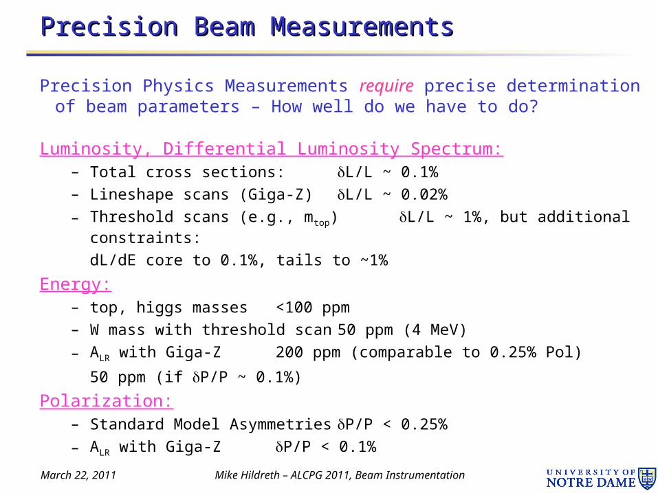
Precision Physics Measurements require precise determination of beam parameters – How well do we have to do?
Luminosity, Differential Luminosity Spectrum:– Total cross sections: L/L ~ 0.1%
– Lineshape scans (Giga-Z) L/L ~ 0.02%
– Threshold scans (e.g., mtop) L/L ~ 1%, but additional constraints:
dL/dE core to 0.1%, tails to ~1%
Energy:– top, higgs masses <100 ppm
– W mass with threshold scan 50 ppm (4 MeV)
– ALR with Giga-Z 200 ppm (comparable to 0.25% Pol)
50 ppm (if P/P ~ 0.1%)
Polarization:– Standard Model Asymmetries P/P < 0.25%
– ALR with Giga-Z P/P < 0.1%
Page 3
March 22, 2011 Mike Hildreth – ALCPG 2011, Beam Instrumentation
Energy MeasurementsEnergy Measurements
• A few words of Motivation...– Energy Calibration needs for Physics at a future Linear Collider will be
similar to what we had at LEPII:
Threshold Scans: Kinematic Fits:
Page 4
March 22, 2011 Mike Hildreth – ALCPG 2011, Beam Instrumentation
Prototypical Energy SpectrometersPrototypical Energy Spectrometers
• “LEP-Type”: BPM based, bend angle measurement
• “SLC-Type”: SR stripe based, bend angle measurement
BPMsec B dp
p
“upstream”
“downstream”
Aim for 10-4 Energy Measurement
Page 5
March 22, 2011 Mike Hildreth – ALCPG 2011, Beam Instrumentation
e.g.: “ILC” Upstream Energy Spectrometere.g.: “ILC” Upstream Energy Spectrometer
• Pure “Displacement” Strategy: Prototype Design
– ILC design: total length of chicane = 54.4 m
– dispersion at center = 5mm (~equal to beam displacement)
• so, 0.5m BPM resolution gives 1x10⁻⁴ measurement (per pulse)
– CLIC Chicane requires 100nm resolution/stability
– Designs incorporated into Accelerator Lattices
16.13
16.13
Incoming Beam
Central BPMs measure offset, offset difference between ±B (cancel some systematic errors)
Outer BPMs required to constrain beam trajectory
all magnets run to ±B5 mm
better resolution would allow intra-train bunch energy measurements
M. Hildreth (Notre Dame), SLAC
Page 6
March 22, 2011 Mike Hildreth – ALCPG 2011, Beam Instrumentation
History: ESA Test Beam ExperimentsHistory: ESA Test Beam Experiments
1. BPM Energy Spectrometer (T-474/491) • PIs: M. Hildreth, Notre Dame, S. Boogert, Royal Holloway, Y. Kolomensky, Berkeley/LBNL • Institutions: Cambridge, DESY, Dubna, Royal Holloway, Notre Dame, UCL, Berkeley, SLAC
– Goals:
• Demonstrate mechanical and electrical stability at 100-nm level
• Perform energy measurement in 4-magnet chicane
• Develop calibration techniques, operational procedures
– multiple BPM triplets to test overall stability, new BPM designs
2. Synchrotron stripe diagnostics (T-475) • PI: E. Torrence, Oregon
• Institutions: Oregon, SLAC
– Goals:
• test chicane scheme with wiggler magnet
• characterize detector (quartz fiber / other) performance and capabilities
Overall Goal:
perform cross-check of two energy measurements at the ~10-4 level
Page 7
March 22, 2011 Mike Hildreth – ALCPG 2011, Beam Instrumentation
T474 (T491), T475: Energy SpectrometersT474 (T491), T475: Energy Spectrometers
• BPM-based and Synchrotron-Stripe Spectrometers can be evaluated in a common four-magnet chicane
DipoleBPMs
Wiggler Synchrotron Stripe Detector
Page 8
March 22, 2011 Mike Hildreth – ALCPG 2011, Beam Instrumentation
FY07 ConfigurationFY07 Configuration
• Ran in 2006 with no dipole chicane• Runs in March, July 2007 with chicane• Simultaneous test of BPM and Synchrotron Stripe Spectrometers
– first beam tests for Synchrotron Detector
– compare measured energy, energy jitter at 100-200ppm level
– tests of BPM movers
– more elaborate mechanical stability monitoring
Dipoles Dipoles
Wiggler
BPMs BPMs BPMsInterf. Station
Straightness Monitor
Page 9
March 22, 2011 Mike Hildreth – ALCPG 2011, Beam Instrumentation
Energy Measurement with chicane (2007)Energy Measurement with chicane (2007)
• Beam energy computed from spectrometer Bdl and BPM offset measurement vs. time
– energy variation from linac energy scan
– large pulse-to-pulse jitter
• Residual between predicted and measured BPM position at chicane center gives a value E ~16 MeV (E/E ~ 5.5×10⁻⁴)
• need higher-precision test
A. Lyapin et al., “Results from a Prototype Chicane-Based Energy Spectrometer for a Linear Collider”, JINST 6 (2011) P02002.
Page 10
March 22, 2011 Mike Hildreth – ALCPG 2011, Beam Instrumentation
Mechanical StabilityMechanical Stability
• Stability requirements determined by overall BPM resolution needed• Mechanical support structure must be designed to limit vibration, and
with minimal thermal expansion properties– Custom temperature regulation needed...
• Stability must be monitored: Interferometry-based system
• Zygo 4004 Measurement System– Design Specs:
• 0.3 nm single-bit resolution
• at up to 5 m/s velocity
• single measurement ~ 7nm
BPMLocal motion measurement
Interferometer heads
Long Baseline Monitoring
Page 11
ATF2 InstallationATF2 Installation
• As of October 2010: three interferometers monitoring three BPMs
March 22, 2011 Mike Hildreth – ALCPG 2011, Beam Instrumentation
QD10BQD10A QM11 QM12 QM13 QM14
BPMBPM MFB2
Optical Path
optical path uses clearance between mover rollers underneath quads
BPMs MFB2 and QD10B are part of vertical steering feedback for beam stability at ATF2 IP. Need resolution stability of ~ 50nm
Page 12
Results from ATF2Results from ATF2
March 22, 2011 Mike Hildreth – ALCPG 2011, Beam Instrumentation
data acquisition at 1 kHz
vibration data on BPM QD10B. rms = 35nm
36-hour drift on BPM QD10B. scale is nm.
one micron
Time (sec)
Time (sec)
interferometer
retroreflector
CCD camera
QD10B
Page 13
Results from ATF2Results from ATF2
March 22, 2011 Mike Hildreth – ALCPG 2011, Beam Instrumentation
50 micron FFTB mover calibration step
• “Relaxation” of mechanical position of BPM MFB2 after calibration move, measured by interferometer
• No corresponding drift seen simultaneously on other BPM support with no mover motion
• analysis ongoing to trace relative beam/BPM motion to prove that this is a physical movement
Time (sec)Time (sec)
“Features” of FFTB mover stability:
BPM MFB2
ZYGO MFB2
po
sitio
n (
nm
)p
osi
tion
(m
)
po
sitio
n (
nm
)500nm
(other studies ongoing: CCD camera stability, interferometer triplet stability/resolution, etc.)
Page 14
End Station A Plans/ScheduleEnd Station A Plans/Schedule
• News from ESTB (End Station Test Beam) Workshop at SLAC, March 17, 2011
– many participants: global interest in high-purity electron test beam
March 22, 2011 Mike Hildreth – ALCPG 2011, Beam Instrumentation
0.25 nC 0.25 nC
Parameters BSY ESA
Energy 13.6 GeV 13.6 GeV
Repetition Rate 5 Hz 5 Hz
Charge per pulse 0.25 nC 0.25 nC
Energy spread, E/E 0.058% 0.058%
Bunch length rms 10 m 280 m
Emittance rms (xy) (1.2, 0.7) 10-6m-rad (4, 1) 10-6 m-rad
Spot size at waist (x,y - < 10 m
Drift Space available for experimental apparatus
- 60 m
Transverse space available for experimental apparatus
- 5 x 5 m
M. Pivi, SLAC
Page 15
End Station A Plans/ScheduleEnd Station A Plans/Schedule
• 4 new kicker magnets including power supplies and modulators and vacuum chambers are designed and components are being ordered and manufactured
• Build new PPS system and install new beam dump
March 22, 2011 Mike Hildreth – ALCPG 2011, Beam Instrumentation
Page 16
End Station A Plans/ScheduleEnd Station A Plans/Schedule
• The complete 4 kickers system will not be ready until the end-of-summer 2011. Short-term solution, installed ~now
– 1 Kicker magnet with stainless steel chamber
– Beryllium target
– System designed for 60 Hz, might work at 120 Hz
– Capacity:• 4 GeV full intensity LCLS beam into ESA.• 4 - 13.6 GeV primary beam into target and generate secondary e- beam to
ESA, 0.1/pulse to 109/pulse.
• By November 2011: Installation of the full 4 kicker magnet system to direct the LCLS beam in ESA.
– Full 14 GeV LCLS beam into ESA
– Production of secondary electron beam down to 1 e- / pulse.
– Future (unfunded) option: secondary hadron beams
March 22, 2011 Mike Hildreth – ALCPG 2011, Beam Instrumentation
Page 17
End Station A Plans/ScheduleEnd Station A Plans/Schedule
• Critical (for Spectrometers and other tests): need precision BPMs– previous BPM sets no longer available
– discussion with LCLS-II, other international sources ongoing
• LCLS-II and Korean FEL both need new precision BPMs
• maybe some joint venture that involves loaning BPMs to ESA for testing and commissioning before they are needed for light sources
– would provide uniform high-precision installation, which would be very beneficial for understanding the analyses
– time-early would be end of 2012
March 22, 2011 Mike Hildreth – ALCPG 2011, Beam Instrumentation
Page 18
SummarySummary
• Termination of ESA program in 2008 limited the current level of precision for spectrometer testing to E/E ~ 5.5×10⁻⁴
– factor 5 larger than what is needed
– will need to revitalize the End Station setup to improve on this
• ATF2 installation exploring stability issues at the 100nm level– 50nm BPM resolution plus 7nm interferometer resolution plus ~100nm
long-range stability monitoring is a powerful system to constrain mechanical motion
– analysis needed!
• ESA Returns!– BPMs needed
– probably 2012 before spectrometer tests can be mounted
March 22, 2011 Mike Hildreth – ALCPG 2011, Beam Instrumentation
Page 19
March 22, 2011 Mike Hildreth – ALCPG 2011, Beam Instrumentation
Interferometer Data from End StationInterferometer Data from End Station
• Vibrations with amplitudes close to or exceeding expected BPM resolution seen on support girder
• Synchronous data acquisition allows interferometer measurement of BPM position to be subtracted in later data analysis
• Resolution of central BPM improved by ~700nm (added in quadrature) after vibration subtraction
BPM support girder clearly needs to be redesigned if we want to do any sort of stability testing...
500nm
500nm
condense
Page 20
March 22, 2011 Mike Hildreth – ALCPG 2011, Beam Instrumentation
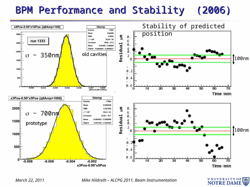
BPM Performance and Stability (2006)BPM Performance and Stability (2006)
~ 350nm
~ 700nm
Stability of predicted position
100nm
100nm
Re
sid
ua
l m
Re
sid
ua
l m
0.6
0.4
0.2
0
-0.2
-0.4
-0.6
0.6
0.4
0.2
0
-0.2
-0.4
-0.6
Page 21
March 22, 2011 Mike Hildreth – ALCPG 2011, Beam Instrumentation
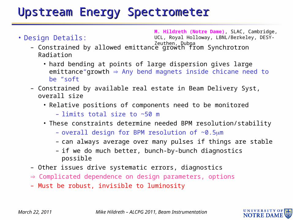
Upstream Energy SpectrometerUpstream Energy Spectrometer
• Design Details:– Constrained by allowed emittance growth from Synchrotron Radiation
• hard bending at points of large dispersion gives large emittance growth Any bend magnets inside chicane need to be “soft”
– Constrained by available real estate in Beam Delivery Syst, overall size
• Relative positions of components need to be monitored
– limits total size to ~50 m
• These constraints determine needed BPM resolution/stability
– overall design for BPM resolution of ~0.5m
– can always average over many pulses if things are stable
– if we do much better, bunch-by-bunch diagnostics possible
– Other issues drive systematic errors, diagnostics
Complicated dependence on design parameters, options
– Must be robust, invisible to luminosity
M. Hildreth (Notre Dame), SLAC, Cambridge, UCL, Royal Holloway, LBNL/Berkeley, DESY-Zeuthen, Dubna
Page 22
March 22, 2011 Mike Hildreth – ALCPG 2011, Beam Instrumentation
Interferometer InstallationInterferometer Installation
July 2006 March 2007
Page 23
March 22, 2011 Mike Hildreth – ALCPG 2011, Beam Instrumentation
BPMs and Electronics BPMs and Electronics
Linac rf cavity BPM
ILC Linac BPM
• SLAC Linac BPMs form main component of instrumentation
– new electronics developed by Y. Kolomensky (Berkeley/LBNL)(LCRD Accelerator R&D)
• Also testing prototype ILC Linac BPMs developed at SLAC (C. Adolphsen)
• New BPMs, optimized for energy spectrometer, designed at University College London in collaboration with BPM experts at SLAC and KEK
– custom electronics– mover system– July 2007
Page 24
March 22, 2011 Mike Hildreth – ALCPG 2011, Beam Instrumentation
Beamline ComponentsBeamline Components
• Dipoles: Measured in SLAC Magnet Lab prior to installation (SLAC/Dubna/Zeuthen)
– RMS Reproducity of field integral: 60ppm
– RMS Agreement across working points: 100ppm
– Temperature coefficient: 5.7x10⁻⁵/°C
– Excellent agreement between measured and simulated magnet properties
– Also: measurements made of residual magnetic fields along entire beamline (Bdl ~ 3 Gm)
• Wiggler refurbished – now installed
Page 25
March 22, 2011 Mike Hildreth – ALCPG 2011, Beam Instrumentation
Interferometer InstallationsInterferometer Installations
• July 2006 • March 2007single BPM station link two BPM stations


![Realtime LEGO Brick Image Retrieval with Cellular Automata...ator [Roberts 1965], the Prewitt operator [Prewitt 1994] and the Marr-Hildreth algorithm [Marr and Hildreth 1980]. Each](https://static.documents.pub/doc/80x56/601a6958d1f3083b4d104dad/realtime-lego-brick-image-retrieval-with-cellular-ator-roberts-1965-the-prewitt.jpg)


