March 3-4, 2008/ARR 1 Power Management Technical Working Group: TRL for Heat and Particle Flux Handling A. René Raffray University of California, San Diego ARIES Meeting UCSD, La Jolla, CA March 3-4, 2008
Transcript
March 3-4, 2008/ARR1
Power Management Technical Working Group: TRL for Heat and Particle Flux Handling
A. René Raffray
University of California, San Diego
ARIES MeetingUCSD, La Jolla, CA
March 3-4, 2008
March 3-4, 2008/ARR2
Heat Flux and Particle Flux Handling1. Scope
• Consequences of particle flux and heat flux on plasma facing components
• Accommodation of threats by PFC’s while providing required lifetime at operating conditions compatible with reasonable power cycle efficiency
• Accommodation of neutron volumetric heat deposition not considered here (gray area with “High Temperature Operation and Power Conversion”)
2. Key science challenges (theory + experiments)
- Material thermomechanics at high temperature (armor+structure)
- Thermal-hydraulic behavior at power producing conditions
- Armor mass loss mechanisms (overlap with “Power Core Lifetime”)
- Ion implantation
- Tritium permeation (overlap with “T inventory & Control”)?
3. Key facilities
• High heat flux test facility (e.g. e-beam)
• Plasma particle flux test facility (PISCES-like, others)
• Integrated heat flux + plasma test facility
• Fusion test facility (ITER, CTF)
• DEMO
March 3-4, 2008/ARR3
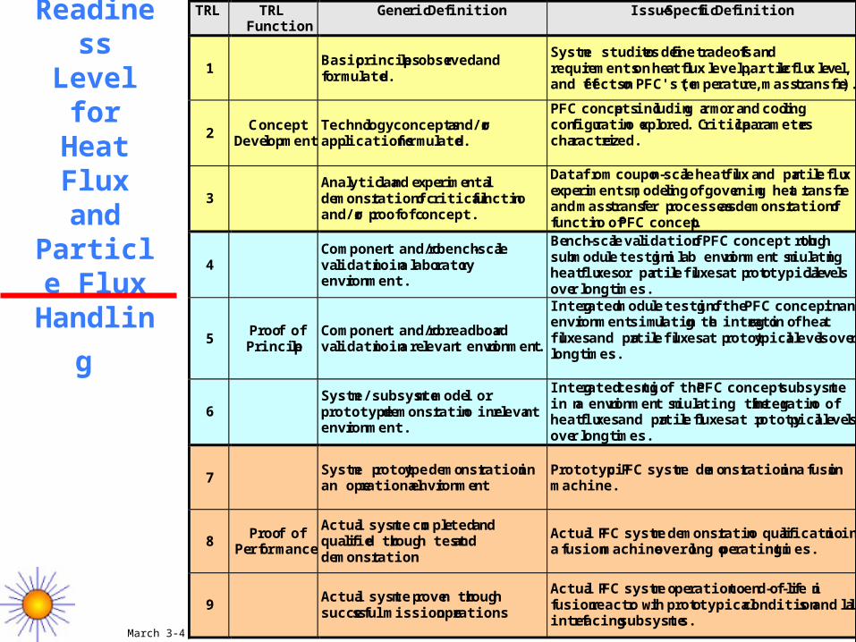
Technical Readiness Level for Heat Flux
and Particle
Flux
Handling
TRL TRL Function
Generic Definition Issue-Specific Definition
1 Basic principles observed and formulated.
System studies to define tradeoffs and requirements on heat flux level, particle flux level, and effects on PFC's (temperature, mass transfer).
PFC concepts including armor and cooling configuration explored. Critical parameters characterized.
3 Analytical and experimental demonstration of critical function and/or proof of concept.
Data from coupon-scale heat flux and particle flux experiments; modeling of governing heat transfer and mass transfer processes as demonstration of function of PFC concept.
4 Component and/or bench-scale validation in a laboratory environment.
Bench-scale validation of PFC concept through submodule testing in lab environment simulating heat fluxes or particle fluxes at prototypical levels over long times.
5 Proof of Principle
Component and/or breadboard validation in a relevant environment.
Integrated module testing of the PFC concept in an environment simulating the integration of heat fluxes and particle fluxes at prototypical levels over long times.
6 System/subsystem model or prototype demonstration in relevant environment.
Integrated testing of the PFC concept subsystem in an environment simulating the integration of heat fluxes and particle fluxes at prototypical levels over long times.
7 System prototype demonstration in an operational environment
Prototypic PFC system demonstration in a fusion machine.
8 Proof of Performance
Actual system completed and qualified through test and demonstration
Actual PFC system demonstration qualification in a fusion machine over long operating times.
9 Actual system proven through successful mission operations
Actual PFC system operation to end-of-life in fusion reactor with prototypical conditions and all interfacing subsystems.
PFC concepts including armor and cooling configuration explored. Critical parameters characterized.
3 Analytical and experimental demonstration of critical function and/or proof of concept.
Data from coupon-scale heat flux and particle flux experiments; modeling of governing heat transfer and mass transfer processes as demonstration of function of PFC concept.
Small-scale facilities: e.g. e-beam and PISCES-like
4 Component and/or bench-scale validation in a laboratory environment.
Bench-scale validation of PFC concept through submodule testing in lab environment simulating heat fluxes or particle fluxes at prototypical levels over long times.
Larger-scale facilities for submodule testing: Heat flux: e.g. larger-scale-beam Particle flux: e.g. larger-scale PISCES-like High-temperature + all expected range of conditions
5 Proof of Principle
Component and/or breadboard validation in a relevant environment.
Integrated module testing of the PFC concept in an environment simulating the integration of heat fluxes and particle fluxes at prototypical levels over long times.
Integrated large facility: Prototypical plasma particle flux+heat flux e.g. an upgraded DIII-D/JET?
6 System/subsystem model or prototype demonstration in relevant environment.
Integrated testing of the PFC concept subsystem in an environment simulating the integration of heat fluxes and particle fluxes at prototypical levels over long times.
Integrated large facility: Prototypical plasma particle flux+heat flux
7 System prototype demonstration in an operational environment
Prototypic PFC system demonstration in a fusion machine.
Fusion machine ITER, CTF
8 Proof of Performance
Actual system completed and qualified through test and demonstration
Actual PFC system demonstration qualification in a fusion machine over long operating times.
CTF
9 Actual system proven through successful mission operations
Actual PFC system operation to end-of-life in fusion reactor with prototypical conditions and all interfacing subsystems.
DEMO
March 3-4, 2008/ARR5
More Detailed Definition of TRL’s for Heat Flux and Particle Flux Handling
• TRL 1. The basic principles guiding the heat and particle flux handling in a fusion power plant are formulated. The magnitude, time scale and footprint of the anticipated fluxes are characterized and bounded, through system studies. The likely effects on the PFC behavior, including heat and mass transfer mechanisms, are hypothesized and their relative importance estimated through system studies.
• TRL 2. Possible PFC concepts that could handle the anticipated heat and particle flux conditions are explored, including armor, structural material and coolant choices and possible integrated configurations. The critical properties and constraints affecting the design are characterized.
• TRL 3. Experimental data from coupon-scale heat flux and particle flux experiments are obtained for candidate armor materials to demonstrate their potential ability to accommodate the anticipated plasma facing conditions. Models are developed to characterize and understand the governing heat transfer and mass transfer processes and to help in extrapolating the small-scale test results to prototypical conditions.
March 3-4, 2008/ARR6
More Detailed Definition of TRL’s for Heat Flux and Particle Flux Handling
• TRL 4. Bench-scale submodule testing of PFC concept is performed in a laboratory environment simulating heat fluxes or particle fluxes at prototypical levels over long times (the heat and particle fluxes need not be integrated). The submodule should represent a unit cell of the PFC concept including armor, structural material and coolant. The testing time should be of the order of the expected operating lifetime. The operating conditions (temperature, pressure, flow rates,..) should cover the expected prototypical conditions.
• TRL 5. Integrated module testing of the PFC concept is performed in an environment simulating the integration of heat fluxes and particle fluxes at prototypical levels over long times. The module should include the integration of a number of unit cells of the PFC concept. The testing time should be of the order of the expected operating lifetime. The operating conditions (temperature, pressure, flow rates,..) should cover the expected prototypical conditions.
• TRL 6. Integrated testing of PFC concept subsystem is performed in an environment simulating the integration of heat fluxes and particle fluxes at prototypical levels over long times. The subsystem should include an integrated unit of modules in a prototypical arrangement, including the integration of the subsystem to any cooled structural support. The testing time should be of the order of the expected operating lifetime. The operating conditions (temperature, pressure, flow rates,..) should cover the expected prototypical conditions.
March 3-4, 2008/ARR7
More Detailed Definition of TRL’s for Heat Flux and Particle Flux Handling
• TRL 7. The PFC system is tested in a fusion machine and its operation demonstrated under prototypical conditions. The test unit should represent the complete PFC system as expected in a power plant.
• TRL 8. The PFC system is tested in a fusion machine and its operation demonstrated under prototypical conditions over long operating times. The test unit should represent the complete PFC system as expected in a power plant. The testing time should be of the order of the expected operating lifetime. Complementary qualification testing of the system in a fusion-like environment through a series of post end-of-life tests is performed to qualify the component.
• TRL 9. The PFC system is fully incorporated in a Demonstration fusion reactor and its performance demonstrated to end-of-life under fully prototypical conditions in a fully integrated mode with all system interfaces.