49
MARINE ILLUSTRATED PARTS MANUAL MODEL MP6.0L L510014 12/02

MARINE
ILLUSTRATED
PARTS MANUAL
MODEL MP6.0L
L510014 12/02

This Page Was
Intentially
Left Blank

MODEL MP6.0L PARTS MANUAL - 1
ZR6
Contents:
Symbols ................................................................................................................................... 2Maintenance Item Part Numbers ................................................................................................... 3Cylinder Block Assembly - Figure 1 ................................................................................................ 4Cylinder Head Assembly / Front Cover - Figure 2 .............................................................................. 6Exhaust Manifold Assembly / Knock Sensors - Figure 3 .................................................................... 10
Intake Manifold Components - Figure 4 ......................................................................................... 12
Oil Pan and Oil Pump Assembly - Figure 5 ..................................................................................... 14
Throttle Body Assemblies and Related Components - Figure 6 .......................................................... 15
Remote Oil Filter Components (Standard Drive) - Figure 7 ................................................................ 16
Remote Oil Filter Components (“V” - Drive) - Figure 8 ...................................................................... 20
Fuel Control Cell (FCC) Components (Standard Drive) - Figure 9 ....................................................... 22
Fuel Control Cell (FCC) Components (“V” - Drive) - Figure 10 ............................................................ 24
Heat Exchanger and Components - Figure 11 ................................................................................ 26
Fresh Water Cooling System Components - Figure 12 ..................................................................... 28
Exhaust Manifold and Components - Figure 13 ............................................................................... 30
Raw Water Cooling Pump - Figure 14 ........................................................................................... 32
Wiring Harness Assemblies and Senders - Figure 15 ....................................................................... 34
ECM and Relays - Figure 16 ....................................................................................................... 36
Accessory Drive System Components - Figure 17 ........................................................................... 38
Starter Assembly Components - Figure 18 ..................................................................................... 40
Engine and Transmission Mounts - Figure 19 ................................................................................. 42
Bellhousing Assembly - Figure 20 ............................................................................................... 44
Transmission and Related Parts (Standard Drive) - Figure 21 ............................................................ 46
“TYPICAL VIEWS ARE SHOWN”ENGINE ROTATIONEngine Rotation is identifi ed as “RH” or “LH” with the engine model number. Rotation always is determined from the fl ywheel end looking toward the front of the engine. In some instances, propeller shaft rotation may be opposite to that of the engine.When ordering a replacement engine, production block or parts for the engine, be certain to check engine rotation. DO NOT rely on propeller rotation in order to determine engine rotation.
LEFT-HAND ROTATION is STANDARD ROTATION.(Flywheel turns counterclockwise when viewed from fl ywheel end of the engine.)
RIGHT-HAND ROTATION is OPPOSITE ROTATION.(Flywheel turns clockwise when viewed from fl ywheel end of the engine.)

MODEL MP6.0L PARTS MANUAL - 2
ZR6
Symbols shown throughout parts list are defi ned here or on the bottom of the individual parts list page. AR = As Required OPT = Optional NSS = Not Serviced Separately NA = Not Available OS = Oversize US = Undersize NS = Not Shown TBD = To Be Determined NI = Not Illustrated
======================================================================
======================================================================
ITEM PART NUMBER DESCRIPTION QUANTITY
1 RB001005I Base Engine Assembly, 6.0L 1
HOW TO READ THIS PARTS BOOK:
1 2 3 4
ITEM NUMBER - This number corresponds with the number in the exploded view on the facing page.
PART NUMBER - This is the designated part number for the particular component or assembly.
DESCRIPTION - This identifi es what the component or assembly is.
QUANTITY - This refers to the number of pieces used.
1
2
3
4

MODEL MP6.0L PARTS MANUAL - 3
ZR6
REPLACEMENT PARTS:
WARNING:Electrical, ignition and fuel system components on PCM Engines are designed and manufactured to comply with U.S. Coast Guard rules and regulations to minimize risks of fi re or explosion.Use of replacement electrical, ignition and fuel system components which do not comply with these rules and regulations could result in a fi re or explosion hazard and should be avoided.
MARINE TRANSMISSIONS:PCM Engines are equipped with PCM or Hurth Transmissions, standard or “V”-drive. If transmission parts are required, contact your dealer or closest PCM Parts Distributor for required parts.Parts manuals and overhaul manuals are available through PCM Distributors.
MAINTENANCE ITEM PART NUMBERS: Description Part Number
Oil Filter R077001 Fuel Filter (FCC) RP080026 Spark Plugs RP030011 Spark Plug Wire Set RK120021 Serpentine Drive Belt R066027 Raw Water Pump Impeller Kit RP061022

MODEL MP6.0L PARTS MANUAL - 4
ZR6
CYLINDER BLOCK ASSEMBLY - FIGURE 1
PC60P_00111-4-02
17
16
18
1920
16
2221
2324
25
15
15
14
13
12
11
10
7
8
1
6
2
5
3
4
91
31
30
29
27
28
26

MODEL MP6.0L PARTS MANUAL - 5
ZR6
ITEM PART NUMBER DESCRIPTION QUANTITY
* RB001021 Base Engine Assembly
1 TBD Bearing Set, camshaft 1
2 TBD Bearing Set, connecting rod (STD) 8
3 TBD Piston, (STD) 8
4 TBD Ring Set, piston (STD) 8
5 TBD Connecting Rod (STD) 8
6 TBD Bolt, connecting rod cap 16
7 TBD Bolt, rear engine cover 12
8 TBD Flywheel Assembly 1
9 TBD Bolt, fl ywheel attaching 6
10 R047236 Seal, crankshaft rear oil 1
11 TBD Cover, rear engine 1
12 TBD Gasket, rear engine cover 1
13 part of item #14 Reluctor Ring, crankshaft 1
14 TBD Crankshaft Assembly 1
15 TBD Bearing Set, crankshaft 1
16 TBD Cap, crankshaft bearing #1 and #5 2
17 TBD Bolt, crankshaft bearing cap side 10
18 TBD Cap, crankshaft bearing #2 - #4 3
19 TBD Stud, crankshaft bearing cap attaching
20 TBD Bolt, crankshaft bearing cap attaching
21 R064016 Balancer, crankshaft 1
22 TBD Bolt, crankshaft balancer 1
23 TBD Oil Pump Assembly 1
24 TBD Drive, oil pump 1
25 TBD Keyway, crankshaft 1
26 TBD Chain, timing 1
27 TBD Bolt, camshaft sprocket attaching 1
28 TBD Sprocket, camshaft 1
29 TBD Bolt, camshaft retainer attaching 3
30 TBD Retainer, camshaft 1
31 TBD Camshaft 1
CYLINDER BLOCK ASSEMBLY - FIGURE 1

MODEL MP6.0L PARTS MANUAL - 6
ZR6
CYLINDER HEAD ASSEMBLY / FRONT COVER - FIGURE 2
PC60P_00410-21-02
44
43
1918
38
20
23
2425
26
35
27
2831
30
32
29
33
34
17
16
36
22
37
39
21
812
1110
9
7
15
13 14
1
2
45
46
50
49
48 47
40
4142
5
43
6
910
11

MODEL MP6.0L PARTS MANUAL - 7
ZR6
ITEM PART NUMBER DESCRIPTION QUANTITY
1 TBD Hose, PCV valve 1
2 TBD Valve, positive crankcase ventilation (PCV) 1
3 TBD Grommet, PCV valve 1
4 TBD Rocker Arm, valve 16
5 TBD Bolt, valve rocker arm attaching 16
6 TBD Guide, valve rocker arm 2
7 TBD Valve Spring Assembly 16
8 TBD Retainer, valve stem 32
9 98443025 Bolt, lifting eye attaching 4
10 93940000 Lockwasher, lifting eye attaching bolt 4
11 R042012 Lifting Eye 2
12 TBD Cap, valve spring 16
13 TBD Seal, valve stem 16
14 TBD Rotator, valve 32
15 TBD Guide, valve stem 16
16 RP030011 Spark Plug 8
17 RK120021 Spark Plug Wire Set 1
18 R020046 Engine Coolant Temperature (ECT) Sensor 1
19 TBD Valve, exhaust (STD) 8
20 TBD Valve, intake (STD) 8
21 TBD Bolt, valve lifter retainer attaching 8
22 TBD Retainer, valve lifter 8
23 RM0280 Gasket, front engine cover 1
24 TBD Cover, front engine 1
25 R047237 Seal, front engine cover oil 1
26 RM0281 Gasket, water circulating pump 2
27 RA057033 Water Circulation Pump Assembly 1
28 TBD Bolt, water circulating pump attaching 4
29 RM0275 Gasket, thermostat housing 2
30 R025036 Housing, thermostat 1
31 TBD Bolt, thermostat housing attaching 2
32 R026002 Thermostat, (160˚ F) 1
33 R109051 Plate, thermostat retainer 1
34 R024208 Water Neck 1
35 TBD Bolt, front engine cover attaching 8
CYLINDER HEAD ASSEMBLY / FRONT COVER - FIGURE 2

MODEL MP6.0L PARTS MANUAL - 8
ZR6
CYLINDER HEAD ASSEMBLY / FRONT COVER - FIGURE 2 (cont’d)
PC60P_00410-21-02
44
43
1918
38
20
23
2425
26
35
27
2831
30
32
29
33
34
17
16
36
22
37
39
21
812
1110
9
7
15
13 14
1
2
45
46
50
49
48 47
40
4142
5
43
6
910
11

MODEL MP6.0L PARTS MANUAL - 9
ZR6
ITEM PART NUMBER DESCRIPTION QUANTITY
36 TBD Lifter, valve 16
37 TBD Push Rod 16
38 RM0278 Gasket, Cylinder Head (LH) 1
NS RM0278 Gasket, Cylinder Head (RH) 1
39 R003016 Cylinder Head 2
40 TBD Bolt, cylinder head (short) 16
41 TBD Bolt, cylinder head (medium) 4
42 TBD Bolt, cylinder head (long) 14
43 TBD Cover, rocker (LH) 1
44 TBD Gasket, rocker cover 2
45 TBD Bolt, rocker cover attaching 8
46 TBD Tube, breather 1
47 TBD Tube, oil fi ll 1
48 R034038B Cap, oil fi ll tube 1
49 TBD Fitting, breather tube 1
50 TBD Cover, rocker (RH) 1
CYLINDER HEAD ASSEMBLY / FRONT COVER - FIGURE 2 (cont’d)

MODEL MP6.0L PARTS MANUAL - 10
ZR6
EXHAUST MANIFOLD / KNOCK SENSORS - FIGURE 3
PC60P_00510-23-02
54
6
1 23
12
11
10
78
9
15
14
13
16
1718

MODEL MP6.0L PARTS MANUAL - 11
ZR6
ITEM PART NUMBER DESCRIPTION QUANTITY
1 TBD Bolt, coolant air bleed pipe attaching 2
2 TBD Pipe, coolant air bleed 1
3 TBD Harness, knock sensor 1
4 TBD Bolt, crankshaft position attaching 1
5 R020044 Sensor, crankshaft position 1
6 TBD Bolt, valley cover attaching 10
7 R020043 Sensor, knock 2
8 TBD Cover, valley 1
9 TBD Gasket, valley cover 1
10 TBD Seal, knock sensor oil 2
11 R020045 Sensor, camshaft position 1
12 TBD Bolt, camshaft position attaching 1
13 R029016 Elbow, exhaust 2
14 RM0274 Gasket, exhaust elbow to manifold 2
15 R028023 Manifold, exhaust 2
16 R031035 Stud, exhaust manifold attaching 12
17 93930000 Lockwasher, exhaust manifold stud attaching 12
18 97330000 Nut, exhaust manifold stud attaching 12
EXHAUST MANIFOLD / KNOCK SENSORS - FIGURE 3

MODEL MP6.0L PARTS MANUAL - 12
ZR6
INTAKE MANIFOLD COMPONENTS - FIGURE 4
PC60P_00912-9-02
1 2
3
4
518
1920
6
7
10
9
11
1213
14
15
16
17
8

MODEL MP6.0L PARTS MANUAL - 13
ZR6
INTAKE MANIFOLD COMPONENTS - FIGURE 4
ITEM PART NUMBER DESCRIPTION QUANTITY
1 R175055 Bolt, engine cover attaching 1
2 R060063 Insert, engine cover 1
3 R060062 Cover, engine 1
4 R117013 Coil, ignition 8
5 R090273 Bracket, ignition coil mounting 2
6 R090268 Bracket, support 2
7 TBD Bolt, fuel rail attaching 4
8 RK120021 Spark Plug Wire Set 1
9 R088003 Regulator, fuel pressure 1
10 R020036 Sensor, manifold absolute pressure (MAP) 1
11 TBD Seal, throttle body 1
12 R062087 Plate, throttle body adapter 1
13 RM0251 Gasket, throttle body 1
14 RA035036 Throttle Body Assembly 1
15 TBD Nut, throttle body attaching 3
16 R002025 Intake Manifold 1
17 RA087008 Fuel Injector Assembly 8
18 RS5126 Bolt, coil bracket attaching 2
19 TBD Bolt, coil bracket attaching 2
20 91107075 Bolt, ignition coil attaching 16

MODEL MP6.0L PARTS MANUAL - 14
ZR6
OIL PAN and OIL PUMP ASSEMBLY - FIGURE 5
PC60P_00211-7-02
24 25
2
1
4
3
5
6
19
10
11
12
15 14 13
18
1716
2021
2223
9
8
7

MODEL MP6.0L PARTS MANUAL - 15
ZR6
ITEM PART NUMBER DESCRIPTION QUANTITY
1 R041079 Tube, oil dipstick 1
2 R041080 Dipstick, oil level (0 to 4 degree) AR
2 R041081 Dipstick, oil level (12 degree) AR
3 RS0302 Bolt, oil dipstick tube attaching 1
4 R127015 Clamp, oil dipstick tube attaching 1
5 RS2180 Lockwasher, oil dipstick tube attaching 1
6 RS1028 Nut, oil dipstick tube attaching 1
7 TBD Bolt, engine rear cover attaching 1
8 R047236 Seal, engine rear cover oil 1
9 TBD Cover, engine rear 1
10 R074030 Tube, oil pickup 1
11 RM0279 Gasket, oil pan 1
12 R005025 Oil Pan 1
13 TBD Bolt, oil sending unit adapter attaching 2
14 TBD Adapter, oil sending unit 1
15 TBD Gasket, oil sending unit adapter 1
16 TBD Bolt, oil pan attaching (long) 2
17 TBD Bolt, oil pan attaching (short) 12
18 TBD Nut, oil pickup tube attaching 1
19 TBD Bolt, oil pickup tube attaching 1
20 TBD Nut, windage tray attaching 10
21 TBD O-ring, oil pickup tube 1
22 R012027 Tray, windage 1
23 TBD Bolt, oil pump attaching 4
24 TBD Oil Pump Assembly 1
25 TBD Drive, oil pump 1
OIL PAN and OIL PUMP ASSEMBLY - FIGURE 5

MODEL MP6.0L PARTS MANUAL - 16
ZR6
THROTTLE BODY and RELATED COMPONENTS - FIGURE 6
1
2
3
4
5
6
7
98
11
12
13
15 14
16
17
18
19
PC60P_010
10

MODEL MP6.0L PARTS MANUAL - 17
ZR6
ITEM PART NUMBER DESCRIPTION QUANTITY
1 R145026 Arrestor, fl ame 1
2 RS3857 Clamp, fl ame arrestor 1
3 R090278 Bracket, perfect pass 1
4 R081008 Throttle Arm, throttle body 1
5 RA035036B Throttle Body Assembly 1
6 R084003 Valve, idle air control 1
7 TBD Screw, IAC valve attaching 2
8 TBD Screw, TP sensor attaching 2
9 R020041 Sensor, throttle position 1
10 R178003 Ball Joint Assembly, cable attaching 1
11 RS2055 Locking Nut, cable clip mounting bolt 2
12 R090267 Throttle Bracket, intake 1
13 R090086 Cable Clip, throttle attaching 1
14 RS5122 Bolt, cable clip mounting 2
15 RS1078 Nut, throttle arm attaching 2
16 TBD Lockwasher, throttle arm attaching 2
17 RS0251 Bolt, throttle arm attaching 2
THROTTLE BODY and RELATED COMPONENTS - FIGURE 6

MODEL MP6.0L PARTS MANUAL - 18
ZR6
REMOTE OIL FILTER COMPONENTS (STANDARD DRIVE) - FIGURE 7
PC60P_01411-8-02
1
3
17
19
20
16
18
4
2
15
14
13
12
11
10
8
7
6
5
9

MODEL MP6.0L PARTS MANUAL - 19
ZR6
ITEM PART NUMBER DESCRIPTION QUANTITY
1 99333020 Bolt, oil fi lter header mounting 3
2 RS2179 Lockwasher, oil fi lter header mounting 3
3 R079066 Oil Filter Header 1
4 R090275 Bracket, oil fi lter header mounting 1
5 95011000 Nut, sender terminal 1
6 95300300 Lockwasher, sender terminal 1
7 R020001 Sender, oil pressure 1
8 R024145 Tee, sender attaching 1
9 R020015A Switch, oil pressure 1
10 TBD Adapter, oil sending unit 1
11 R047240 O-ring, oil bypass adapter 1
12 R079067 Adapter, oil bypass 1
13 R047202 O-ring, oil bypass adapter attaching fi tting 1
14 R079068 Nut, oil bypass adapter attaching 1
15 R024184 Fitting, 90 degree 1
16 RA045120D Hose Assembly, fi lter header to bypass adapter 1
17 RA045120D Hose Assembly, bypass adapter to fi lter header 1
18 R024148 Fitting, straight 1
19 R077001 Filter, oil 1
20 R024203 Nipple, header fi lter adapter 1
REMOTE OIL FILTER COMPONENTS (STANDARD DRIVE) - FIGURE 7

MODEL MP6.0L PARTS MANUAL - 20
ZR6
REMOTE OIL FILTER COMPONENTS (“V” - DRIVE) - FIGURE 8
PC60P_01511-7-02
4
3
1
2
5
6
7
8
14
15
13
12
10
11
16
17
18
19
9

MODEL MP6.0L PARTS MANUAL - 21
ZR6
REMOTE OIL FILTER COMPONENTS (“V” - DRIVE) - FIGURE 8
ITEM PART NUMBER DESCRIPTION QUANTITY
1 R090275 Bracket, oil fi lter header mounting 1
2 R079066 Oil Filter Header 1
3 R024203 Nipple, header fi lter adapter 1
4 R077001 Filter, oil 1
5 RS2179 Lockwasher, oil fi lter header mounting 3
6 99333020 Bolt, oil fi lter header mounting 3
7 RA045120 Hose Assembly, bypass adapter to fi lter header 1
8 RA045120 Hose Assembly, fi lter header to bypass adapter 1
9 R024184 Fitting, 90 degree 2
10 R079068 Fitting, oil bypass adapter attaching 1
11 R047202 O-ring, oil bypass adapter attaching fi tting 1
12 R079067 Adapter, oil bypass 1
13 R047240 O-ring, oil bypass adapter 1
14 TBD Adapter, oil sending unit 1
15 R020015A Switch, oil pressure 1
16 R024145 Tee, sender attaching 1
17 R020001 Sender, oil pressure 1
18 95300300 Lockwasher, sender terminal 1
19 95011000 Nut, sender terminal 1

MODEL MP6.0L PARTS MANUAL - 22
ZR6
FUEL CONTROL CELL (FCC) COMPONENTS (STANDARD DRIVE) - FIGURE 9
3
5
8
9
1112
13
14
15
16
18
17
1920
1021
2223
6
74
21
PC60P_00812-9-02
2524

MODEL MP6.0L PARTS MANUAL - 23
ZR6
ITEM PART NUMBER DESCRIPTION QUANTITY
1 TBD Fitting, fuel pressure 1
2 TBD Fitting, fuel line 1
3 TBD Fitting, fuel line 1
4 part of item #5 O-ring, FCC sealing 1
5 RP080026 Filter, FCC fuel 1
6 RA085090C Hose Assembly, FCC to fuel rail (inlet) 1
7 RA085091C Hose Assembly, fuel rail to FCC (return) 1
8 90384075 Bolt, FCC mounting 3
9 R090276 Bracket, FCC mounting 1
10 R024089 Fitting, 90 degree 1
11 RS1521L Locking Nut, low-pressure fuel pump 3
12 R096142 Washer, fuel pump mounting 3
13 R094035A Grommet, mounting bracket 3
14 R090280 Bracket, low-pressure fuel pump mounting 1
15 R096141 Washer, fuel pump mounting 3
16 R024089 Fitting, 90 degree 1
17 RA080018 Fuel Pump, low-pressure 1
18 R024192 Fitting, 90 degree 1
19 RA085070A Hose Assembly, low-pressure pump to FCC 1
20 RA080029 Fuel Control Cell Assembly 1
21 R024163 Fitting, 90 degree 1
22 98443025 Bolt, FCC mounting bracket 2
23 RS7070 Lockwasher, FCC mounting bracket 2
24 93940000 Lockwasher, bracket attaching 1
25 98443025 Bolt, bracket attaching 1
FUEL CONTROL CELL (FCC) COMPONENTS (STANDARD DRIVE) - FIGURE 9

MODEL MP6.0L PARTS MANUAL - 24
ZR6
FUEL CONTROL CELL (FCC) COMPONENTS (“V” - DRIVE) - FIGURE 10
2021
22
13
19
18
17
16
13
12
1011
9
8
6
7
2423
14
15
3
5
4
21
PC60P_01312-9-02

MODEL MP6.0L PARTS MANUAL - 25
ZR6
ITEM PART NUMBER DESCRIPTION QUANTITY
1 TBD Fitting, fuel pressure 1
2 TBD Fitting, fuel line 1
3 TBD Fitting, fuel line 1
4 part of item #5 O-ring, FCC sealing 1
5 RP080026 Filter, FCC fuel 1
6 RA085090B Hose Assembly, FCC to fuel rail (inlet) 1
7 RA085091B Hose Assembly, fuel rail to FCC (return) 1
8 TBD Bolt, FCC mounting 3
9 R090277 Bracket, FCC mounting 1
10 RS7070 Lockwasher, FCC mounting bracket 2
11 98443025 Bolt, FCC mounting bracket 2
12 R024089 Fitting, 90 degree 1
13 R024163 Fitting, 90 degree 2
14 RA080029 Fuel Control Cell Assembly 1
15 RA085071B Hose Assembly, low-pressure pump to FCC 1
16 RS1521L Locking Nut, low-pressure fuel pump 3
17 R096142 Washer, fuel pump mounting 3
18 R094035 Grommet, mounting bracket 3
19 R090280 Bracket, low-pressure fuel pump mounting 1
20 R096141 Washer, fuel pump mounting 3
21 R024089 Fitting, 90 degree 1
22 RA080018 Fuel Pump, low-pressure 1
23 93940000 Lockwasher, bracket attaching 1
24 98443025 Bolt, bracket attaching 1
FUEL CONTROL CELL (FCC) COMPONENTS (“V” - DRIVE) - FIGURE 10

MODEL MP6.0L PARTS MANUAL - 26
ZR6
HEAT EXCHANGER and COMPONENTS - FIGURE 11
12
4
5
14
10
6
3
8
9
13
12
11
7
PC60P_00712-9-02

MODEL MP6.0L PARTS MANUAL - 27
ZR6
ITEM PART NUMBER DESCRIPTION QUANTITY
1 R034045 Cap, degas bottle 1
2 R146001 Bottle, degas 1
3 RS3872 Clamp, hose 2
4 TBD Hose, degas bottle to heat exchanger 1
5 TBD Anode, sacrifi cial zinc AR
6 RS1078 Nut, ground wire stud 1
7 R101013 Wire, grounding 1
8 RA147047 Heat Exchanger Assembly 1
9 R034034 End Cap Kit, exchanger AR
10 R094040 Isolator, rubber 2
11 R090279 Bracket, heat exchanger 1
12 RS0304 Bolt, heat exchanger bracket attaching 2
13 RS2380 Lockwasher, mounting bolt 2
14 RS3857 Clamp, exchanger mounting 2
HEAT EXCHANGER and COMPONENTS - FIGURE 11

MODEL MP6.0L PARTS MANUAL - 28
ZR6
FRESH WATER COOLING SYSTEM COMPONENTS - FIGURE 12
20
2131
31
19
18
10
22
23
2425
26
31
1716
731
12
8 13
15
27
3329
28 32
15
30
8
1
8
23245
6
34
9
10
11
8
14
31
PC60P_00612-9-02

MODEL MP6.0L PARTS MANUAL - 29
ZR6
ITEM PART NUMBER DESCRIPTION QUANTITY
1 R045151 Hose, exchanger to exhaust manifold (Starboard STD) 1
2 RS3872 Clamp, hose 2
3 TBD Hose, degas bottle to heat exchanger 1
4 R034045 Cap, degas bottle 1
5 R146001 Bottle, degas 1
6 R127087 Clamp, hose (5/8” - degas bottle) 1
7 R045132 Hose, coolant air bleed to bottle 1
8 RS3851 Clamp, hose (1”) 4
9 R045149 Hose, circ. pump to heat exchanger 1
10 RS3868 Clamp, hose (1 1/2”) 2
11 R045148 Hose, exchanger to thermostat housing 1
12 R045150 Hose, exchanger to exhaust manifold (Port STD) 1
13 R024006A Fitting, 90 degree 1
14 R147014 Cooler, transmission oil 1
15 113186 Plug, manifold 2
16 TBD Tube, coolant air bleed 1
17 RM0281 Gasket, water pump to engine block 2
18 RA057033 Water Pump Assembly 1
19 RA057032 Raw Water Pump 1
20 R045152 Hose, transmission cooler to raw water pump 1
21 R045147 Hose, raw water pump to exchanger 1
22 RM0275 Gasket, thermostat housing 2
23 R025036 Thermostat Housing 1
24 R109051 Plate, thermostat retainer 1
25 R026002 Thermostat, (160 degree) 1
26 R024208 Water Neck 1
27 TBD Hose, coolant bypass fi tting (3/4” bulk) 1
28 R024210 Bypass, coolant 1
29 20806 Hose, coolant bypass fi tting (5/8” bulk) 1
30 R024073 Fitting, manifold straight 1
31 RS3858 Clamp, hose (1 1/4”) 6
32 TBD Clamp, hose (1 1/16” oetiker) 2
33 TBD Clamp, hose (1” oetiker) 2
34 R127084 Clamp, hose (vent tube) 1
FRESH WATER COOLING SYSTEM COMPONENTS - FIGURE 12

MODEL MP6.0L PARTS MANUAL - 30
ZR6
EXHAUST MANIFOLD and COMPONENTS - FIGURE 13
PC60P_012-9-02
6
7
8
5
3
10
9
11
1
1
2
2
4

MODEL MP6.0L PARTS MANUAL - 31
ZR6
ITEM PART NUMBER DESCRIPTION QUANTITY
1 RS1527 Nut, exhaust elbow attaching 8
2 RS2179 Lockwasher, exhaust elbow attaching 8
3 RM0274 Gasket, manifold to exhaust elbow 2
4 R031036 Stud, exhaust elbow attaching (short) 4
5 R028023 Exhaust Manifold Assembly 2
6 R031035 Stud, manifold to cylinder head attaching 12
7 RS2179 Lockwasher, manifold to cylinder head attaching 12
8 RS7026 Nut, manifold to cylinder head attaching 12
9 RM0276 Gasket, manifold to cylinder head 2
10 R029016 Exhaust Elbow Assembly 2
11 R031037 Stud, exhaust elbow attaching (long) 4
12 R096144 Retainer, spark plug wire clip 2
13 922200020 Washer, retainer attaching 2
14 RS2179 Lockwasher, retainer attaching 2
15 RS0280 Bolt, retainer attaching 2
16 R127090 Clip, spark plug wires 2
17 R127062 Gasket, spark plug wires 2
*NOTE: See Fresh Water Cooling section for parts used on Fresh Water Cooled engines.
EXHAUST MANIFOLD and COMPONENTS - FIGURE 13

MODEL MP6.0L PARTS MANUAL - 32
ZR6
RAW WATER COOLING PUMP - FIGURE 14
PC60P_02211-11-02
1

MODEL MP6.0L PARTS MANUAL - 33
ZR6
ITEM PART NUMBER DESCRIPTION QUANTITY
1 RA057032 Raw Water Pump Assembly 1
NS RP061022 Kit, impeller 1
RAW WATER COOLING PUMP - FIGURE 14

MODEL MP6.0L PARTS MANUAL - 34
ZR6
WIRING HARNESS ASSEMBLIES and SENDERS - FIGURE 15
5 4
3
2
1
6
24
3
45
PC60P_02311-12-02
78
13
12
15
16
11
10
9
14

MODEL MP6.0L PARTS MANUAL - 35
ZR6
WIRING HARNESS ASSEMBLIES and SENDERS - FIGURE 15
ITEM PART NUMBER DESCRIPTION QUANTITY
1 95011000 Nut, sender terminal 1
2 95300300 Lockwasher, sender terminal 1
3 92300200 Washer, sender terminal 1
4 R020003 Sender, temperature 1
5 R020019 Sensor, engine coolant temperature (ECT) 1
6 RA121076 Engine Wiring Harness Assembly 1
7 R096142 Washer, main harness attaching 4
8 RS5115 Screw, main harness attaching 4
9 95011000 Nut, sender terminal 1
10 95300300 Lockwasher, sender terminal 1
11 R020001 Sender, oil pressure 1
12 R024145 Tee, sender attaching 1
13 TBD Adapter, oil sending unit 1
14 R020015A Switch, oil pressure 1
15 TBD Harness, ignition coil 2
16 R121078 Harness, FCC (“V” - Drive) AR

MODEL MP6.0L PARTS MANUAL - 36
ZR6
ECM and RELAYS - FIGURE 16
PC60P_01711-7-02
2 3
4
5
61
7
8
9
10
11
12
13
14
15
16

MODEL MP6.0L PARTS MANUAL - 37
ZR6
ITEM PART NUMBER DESCRIPTION QUANTITY
1 R153006C Circuit Breaker Assembly (60 amp) 1
2 RS5084 Bolt, circuit breaker mounting 2
3 91107075 Bolt, circuit breaker bracket attaching 2
4 R090274 Bracket, circuit breaker mounting 1
5 RS0302 Bolt, oil dipstick tube attaching 1
6 R130012 Relay, fuel pump, ignition, starter 3
7 R116019 Engine Control Module 1
8 91107075 Bolt, ECM attaching 3
9 R126014 Cover, fuse holder 1
10 R153017B Fuses, 20 amp 3
11 RS0304 Bolt, bracket attaching 2
12 RS2180 Lockwasher, bracket attaching bolt 2
13 RS1028 Nut, oil dipstick tube attaching 1
14 RS2180 Lockwasher, oil dipstick tube attaching 1
15 R127015 Clamp, oil dipstick tube attaching 1
16 R090279 Bracket, ECM/relay mounting 1
ECM and RELAYS - FIGURE 16

MODEL MP6.0L PARTS MANUAL - 38
ZR6
ACCESSORY DRIVE SYSTEM COMPONENTS - FIGURE 17
Bel
tTe
nsi
on
er
Cir
cula
tio
nP
um
pR
aw W
ater
Pu
mp
Cra
nks
haf
tP
ulle
y
Alt
ern
ato
r
Idle
r
A
23
1
2
3
4
24
5
679
8
10
11
13
14
12
15
1617
1920
18
2122
2512
PC60P_01211-5-02

MODEL MP6.0L PARTS MANUAL - 39
ZR6
ITEM PART NUMBER DESCRIPTION QUANTITY
1 R066027 Belt, serpentine drive 1
2 part of item #5 Bolt, tensioner pulley attaching 1
3 part of item #5 Washer, tensioner pulley attaching bolt 1
4 part of item #5 Pulley, tensioner 1
5 RA068001 Tensioner, belt 1
6 TBD Bolt, idler pulley attaching 1
7 TBD Lockwasher, idler pulley attaching bolt 1
8 TBD Washer, idler pulley attaching bolt (small) 1
9 R096145 Washer, idler pulley attaching bolt (large) 1
10 R065040 Pulley, idler 1
11 R090269 Bracket, idler pulley mounting / alternator 1
12 RS7070 Lockwasher, idler pulley bracket attaching bolt 2
13 TBD Bolt, idler pulley bracket attaching 1
14 98443110 Bolt, alternator mounting 1
15 RA057032 Raw Water Pump Assembly 1
16 Lockwasher, raw water pump mounting bolt 2
17 98337016 Bolt, raw water pump mounting 2
18 R065050 Pulley, raw water pump 1
19 TBD Lockwasher, raw water pump pulley attaching bolt 3
20 TBD Bolt, raw water pump pulley attaching 3
21 R064016 Balancer, crankshaft 1
22 TBD Bolt, crankshaft balancer 1
23 TBD Bolt, water circulation pump attaching 4
24 TBD Bolt, belt tensioner mounting 3
25 RA097007C Alternator Assembly 1
ACCESSORY DRIVE SYSTEM COMPONENTS - FIGURE 17

MODEL MP6.0L PARTS MANUAL - 40
ZR6
STARTER ASSEMBLY COMPONENTS - FIGURE 18
PC60P_01611-8-02
23
4
67
1
5

MODEL MP6.0L PARTS MANUAL - 41
ZR6
ITEM PART NUMBER DESCRIPTION QUANTITY
1 RS7019 Nut, solenoid terminal 1
2 TBD Lockwasher, solenoid terminal 1
3 TBD Solenoid, starter 1
4 R009203 Bolt, starter mounting 2
5 RA122019 Starter Motor Assembly 1
6 93003000 Lockwasher, solenoid terminal 1
7 RS7036 Nut, solenoid terminal 1
STARTER ASSEMBLY COMPONENTS - FIGURE 18

MODEL MP6.0L PARTS MANUAL - 42
ZR6
ENGINE and TRANSMISSION MOUNTS - FIGURE 19
PC60P_01911-11-02
7
13
14
12
15
51
16
6
6
12
3
5
4
7
8
9
7
1011
Engine Mount GroupFront Mount
Engine Mount GroupRear Mount

MODEL MP6.0L PARTS MANUAL - 43
ZR6
ENGINE and TRANSMISSION MOUNTS - FIGURE 19
ITEM PART NUMBER DESCRIPTION QUANTITY
1 R095020 Bolt, trunion clamp 2
2 RS7070 Lockwasher, engine mount attaching bolt 8
3 RS6556 Bolt, engine mount attaching 8
4 R090242 Mount, engine front 2
5 RS2181 Lockwasher, trunion clamp bolt 2
6 RS1529 Nut, trunnion clano bolt 2
7 RS1075 Nut, adjustment and lock 4
8 RS2186 Lockwasher, adjusting nut 2
9 R091001 Trunnion 2
10 RC091001 Trunnion Assembly 1
11 RA092016 Trunnion Assembly 1
12 RA092011A Trunnion Assembly 1
12 RA092011 Trunnion Assembly (V-drive) 1
13 R091003 Trunnion 2
14 RS0329 Bolt, rear mount attaching 4
14 RS0328 Bolt, rear mount attaching (V-drive) 4
15 RS2181 Lockwasher, rear mount attaching bolt 4
16 R090205 Mount, rear (1.23:1) 1
NS R090145 Mount, rear (1.:1) 1
MODEL MP6.0L PARTS MANUAL - 44
ZR6
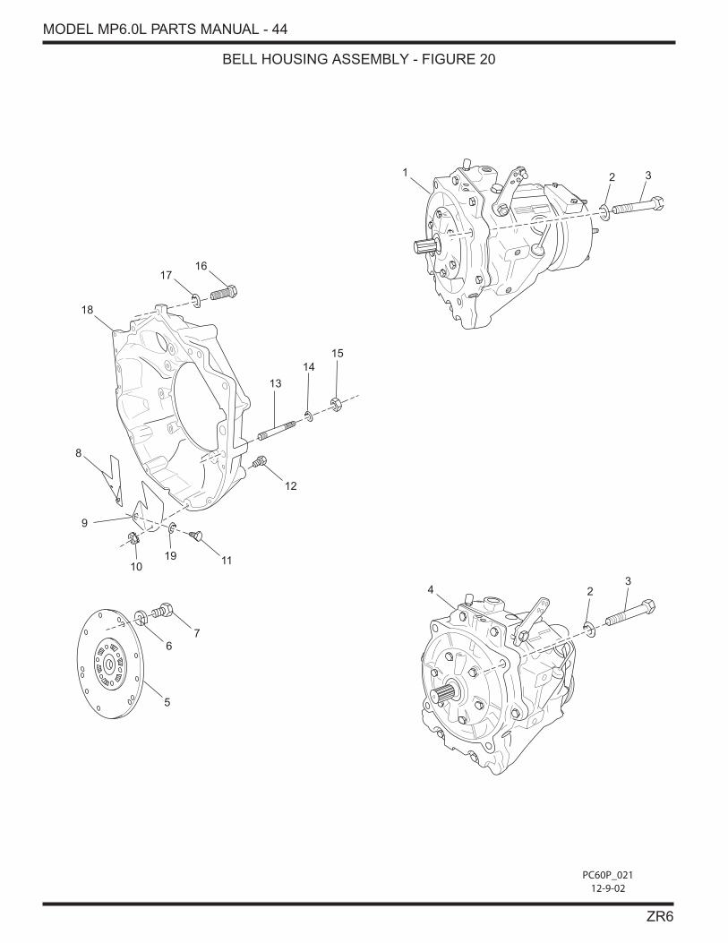
BELL HOUSING ASSEMBLY - FIGURE 20
PC60P_02112-9-02
5
67
1019 11
9
8
18
1716
13
1415
12
1 2 3
23
4

MODEL MP6.0L PARTS MANUAL - 45
ZR6
BELL HOUSING ASSEMBLY - FIGURE 20
ITEM PART NUMBER DESCRIPTION QUANTITY
1 RA157016 Transmission Assembly, (1:1) AR
NS R079056 Adapter, V-Drive AR
2 RS2181 Lockwasher, transmission attaching bolt 4
3 RS0334 Bolt, transmission attaching 4
4 RA157017 Transmission Assembly, (1.23:1) AR
5 R140016 Plate, damper 1
6 RS7070 Lockwasher, damper plate attaching bolt 6
7 98446030 Bolt, damper plate attaching 6
8 R019011 Cover, dust (stbd) 1
9 R019012 Cover, dust (port) 1
10 RS1078 Nut, dust cover attaching 2
11 RS6503 Bolt, dust cover attaching 2
12 RS0256 Bolt, dust cover attaching 2
13 R031034 Stud, bellhousing attaching 2
14 RS7070 Lockwasher, bellhousing attaching 2
15 97440000 Nut, bellhousing attaching 2
16 RS6556 Bolt, bellhousing attaching 2
17 RS7070 Lockwasher, bellhousing attaching 2
18 R142014A Bellhousing 1
19 93920000 Lockwasher, dust cover attaching 2

MODEL MP6.0L PARTS MANUAL - 46
ZR6
TRANSMISSION AND RELATED COMPONENTS (STANDARD DRIVE) - FIGURE 21
A
6
8
9
10
11
7
PC60P_01811-8-02
2
3
5
4
1
A - FRONT MOUNT SHIFT BRACKET

MODEL MP6.0L PARTS MANUAL - 47
ZR6
ITEM PART NUMBER DESCRIPTION QUANTITY
1 R090086 Cable Clip, single cable 1
2 RS5122 Bolt, cable clip attaching 2
3 R090143A Bracket, shift 1
4 RS2055 Nut, cable clip attaching bolt 2
5 R024010 Fitting, 90 degree 1
6 R024053 Fitting, 45 degree 1
7 RA157017 Transmission, 1.23:1 1
8 RA045007B Hose Assembly, cooler to transmission 1
9 R147014 Transmission Cooler Assembly 1
10 R024010 Fitting, 90 degree 2
11 RA045007T Hose Assembly, transmission to cooler 1
TRANSMISSION AND RELATED COMPONENTS (STANDARD DRIVE) - FIGURE 21


