Marine IsoBoost Transformers Marine IsoBoost Transformers - System Brochure Perfect for new builds and retrofits the range offers both standard and bespoke options that can be used worldwide.
Transcript
Marine IsoBoost Transformers
Marine IsoBoost Transformers - System BrochurePerfect for new builds and retrofits the range offers both standard and bespoke options that can be used worldwide.
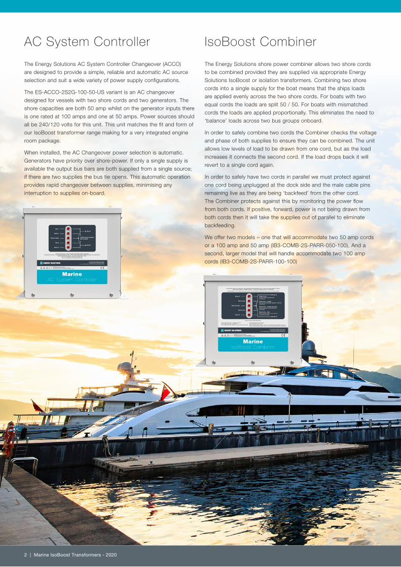
AC System Controller
The Energy Solutions AC System Controller Changeover (ACCO)
are designed to provide a simple, reliable and automatic AC source
selection and suit a wide variety of power supply configurations.
The ES-ACCO-2S2G-100-50-US variant is an AC changeover
designed for vessels with two shore cords and two generators. The
shore capacities are both 50 amp whilst on the generator inputs there
is one rated at 100 amps and one at 50 amps. Power sources should
all be 240/120 volts for this unit. This unit matches the fit and form of
our IsoBoost transformer range making for a very integrated engine
room package.
When installed, the AC Changeover power selection is automatic.
Generators have priority over shore-power. If only a single supply is
available the output bus bars are both supplied from a single source;
if there are two supplies the bus tie opens. This automatic operation
provides rapid changeover between supplies, minimising any
interruption to supplies on-board.
IsoBoost Combiner
The Energy Solutions shore power combiner allows two shore cords
to be combined provided they are supplied via appropriate Energy
Solutions IsoBoost or isolation transformers. Combining two shore
cords into a single supply for the boat means that the ships loads
are applied evenly across the two shore cords. For boats with two
equal cords the loads are split 50 / 50. For boats with mismatched
cords the loads are applied proportionally. This eliminates the need to
‘balance’ loads across two bus groups onboard.
In order to safely combine two cords the Combiner checks the voltage
and phase of both supplies to ensure they can be combined. The unit
allows low levels of load to be drawn from one cord, but as the load
increases it connects the second cord. If the load drops back it will
revert to a single cord again.
In order to safely have two cords in parallel we must protect against
one cord being unplugged at the dock side and the male cable pins
remaining live as they are being ‘backfeed’ from the other cord.
The Combiner protects against this by monitoring the power flow
from both cords. If positive, forward, power is not being drawn from
both cords then it will take the supplies out of parallel to eliminate
backfeeding.
We offer two models – one that will accommodate two 50 amp cords
or a 100 amp and 50 amp (IB3-COMB-2S-PARR-050-100), And a
second, larger model that will handle accommodate two 100 amp
cords (IB3-COMB-2S-PARR-100-100)
2 | Marine IsoBoost Transformers - 2020
IsoBoost TransformersThe Energy Solutions IsoBoost transformer provides a cost effective
and reliable solution to isolate and manage a shore line. It provides all
of the features of a normal isolation transformer, as well as providing
a boost function to manage the volt drop on heavily loaded shore
lines, or to cope with a 208V (phase to phase) supply. On startup,
the isolation transformer automatically soft starts the transformer to
prevent inrush from tripping the supply breaker. If the voltage is in
range, it operates in 1:1 mode, so that the output voltage matches the
input voltage. If the supply voltage drops below 215V, it automatically
switches into boost mode, effectively raising the output voltage by
around 10%. If the supply voltage recovers, the IsoBoost automatically
switches back to 1:1 operation.
• Double wound isolation transformer to BS EN 60076-1.
• Custom enclosure, powder coated RAL9016 traffic white finish.
• Input is automatically switchable between 208/400 (configured at
time of order) and 240 volts nominal.
• Protective screen between input and output windings (normally
connected to incoming earth)
• Output is 240 volt nominal, with centre tap available.
• Dual frequency (but no frequency conversion)
• Input 3 wire (earth and two conductors)
• Output options for 3 wire or 4 wire
• Models available for US or EU operation (208V or 400V).
• Automatic soft start to prevent shore supply tripping
• Inbuilt metering, logging and power analysis
• Fit and form replacement for Charles Industries™ Isoboost
transformers
A sophisticated power meter is built into the case of the
IsoBoost. It provides detailed monitoring of the output supply
of the transformer, allowing the user to check that the supply
is acceptable before connecting it to the vessel switchboard.
The power monitor is also used to provide the control of the
boosting function. It includes the following features:
• Voltage, frequency, current monitoring
• Power, power factor and energy usage
• Harmonic content and THD
• Event and alarm recording
• Modbus RTU communication for optional remote display
Boost function
The output voltage of the transformer is directly related to the input voltage. This output voltage, when the transformer is in Boost mode, is +10% higher than the input voltage on the European specification transformers and +15% higher than the input voltage on US specification transformers. The boost function will typically happen at the following voltage levels:
European Spec: Input Voltage is below 216V USA Spec: Input Voltage is below 216V
Buck function (24 kVA Euro spec only)
The European spec 24 kVA IsoBoost unit operates differently to the rest of the range. This model has a 1:1 mode for when the vessel can only get a 230 volt single phase supply. However, if the boat can access a 400 volt three phase outlet then the transformer will accept any two phases into it’s input and then select a drop down winding (buck winding) to drop the 400 volts down to 230 volts for on-board use. The extra voltage means you get more power from a certain amperage connector. For instance a 100 amp connection at 230 volts gives 23 kW of onboard power – but a 63 amp 400 volt supply will give 25 kW. For single phase boats with high onboard loads the ability to access three phase dock side outlets is a massive benefit.
Marine IsoBoost Transformers - 2020 | 3
12kVA IsoBoostIB3
12kVA IsoBoostIB3
AC System Controller100/50
Imb
alan
ced
Lo
ad
100A MaxMCB
50AMax MCB
G
G
Bus ACircuits
Bus BCircuits
Generators
25A
50A
25A
50AMarineIso-Boost Transformer
MarineIso-Boost Transformer
Gen 1
Shore 1
Bus tie active
Gen 2
Shore 2
Bus A
Bus B
Single source suppliesBus A and B
MarineAC System Controller
Imb
alan
ced
Lo
ad
12kVA IsoBoostIB3
AC System Controller100/50
100AMCB
50AMax MCB
G
G
Bus ACircuits
Bus BCircuits
Generators
25A
50A
25A
50A
24kVA IsoBoostIB4
MarineIso-Boost Transformer
MarineIso-Boost Transformer
Gen 1
Shore 1
Bus tie active
Gen 2
Shore 2
Bus A
Bus B
Single source suppliesBus A and B
MarineAC System Controller
Allows for 2 x 240 volt shore cords (1 x 100 amp and 1 x 50 amp) and a 24 kVA generator and 12 kVA generator.Twin shore-cords supply one output bus each. Mismatched bus loads cause mismatched shore supplies.
Allows for 2 x 240 volt shore cords (2 x 50 amp) and a 24 kVA generator and 12 kVA generator.Twin shore-cords supply one output bus each. Mismatched bus loads cause mismatched shore supplies.
Scheme 20
Scheme 21
Sample Systems - IsoBoost transformers with split bus shore power operation
4 | Marine IsoBoost Transformers - 2020
Scheme 22
Scheme 30
Allows for 2 x 240 volt shore cords (2 x 100 amp) and a 2 x 24 kVA generator.Twin shore-cords supply one output bus each. Mismatched bus loads cause mismatched shore supplies.
Allows for 2 x 240 volt shore cords (2 x 50 amp) and a 24 kVA generator and 12 kVA generator.Twin shore-cords combine to supply the ships load. Mismatched bus loads are balanced 50/50 across the shore supplies.
Imb
alan
ced
Lo
ad
Generators
24kVA IsoBoostIB3
24kVA IsoBoostIB3
AC System Controller100/100
Bus ACircuits
Bus BCircuits
100A MaxMCB
100AMax MCB
GG
MarineIso-Boost Transformer
MarineIso-Boost Transformer
Gen 1
Shore 1
Bus tie active
Gen 2
Shore 2
Bus A
Bus B
Single source suppliesBus A and B
MarineAC System Controller
25A
50A
25A
50A
Bal
ance
d L
oad
AC System Controller100/50
Generators
Iso-Boost Combiner100/50
Bus ACircuits
Bus BCircuits
50A MaxMCB
50AMax MCB
GG
25A
50A
12kVA IsoBoostIB3
12kVA IsoBoostIB3
37A
37AMarineIso-Boost Transformer
MarineIso-Boost Transformer
Gen 1
Shore 1
Bus tie active
Gen 2
Shore 2
Bus A
Bus B
Single source suppliesBus A and B
MarineAC System Controller
Gen 1
Shore 1
Bus tie active
Gen 2
Shore 2
Bus A
Bus B
Single source suppliesBus A and B
MarineIso-Boost Combiner
Sample Systems - IsoBoost transformers with parallel bus shore power operation
Marine IsoBoost Transformers - 2020 | 5
Allows for 2 x 240 volt shore cords (1 x 100 amp and 1 x 50 amp) and a 24 kVA generator and 12 kVA generator.Twin shore-cords combine to supply the ships load. Mismatched bus loads are balanced 66/33 across the shore supplies.
Allows for 2 x 240 volt shore cords (2 x 100 amp) and a 2 x 24 kVA generator.Twin shore-cords combine to supply the ships load. Mismatched bus loads are balanced 50/50 across the shore supplies.
Scheme 31
Scheme 32
Pro
po
rtio
nate
lyB
alan
ced
Lo
ad
Generators
12kVA IsoBoostIB3
Bus ACircuits
Bus BCircuits
100A MaxMCB
50AMax MCB
GG
24kVA IsoBoostIB4
25A
50A
MarineIso-Boost Transformer
50A
25AMarineIso-Boost Transformer
AC System Controller100/50
Iso-Boost Combiner100/50
Gen 1
Shore 1
Bus tie active
Gen 2
Shore 2
Bus A
Bus B
Single source suppliesBus A and B
MarineAC System Controller
Gen 1
Shore 1
Bus tie active
Gen 2
Shore 2
Bus A
Bus B
Single source suppliesBus A and B
MarineIso-Boost Combiner
Bal
ance
d L
oad
Generators
AC System Controller100/100
Iso-Boost Combiner100/100
Bus ACircuits
Bus BCircuits
100A MaxMCB
100AMax MCB
GG
24kVA IsoBoostIB3
24kVA IsoBoostIB3
MarineIso-Boost Transformer
MarineIso-Boost Transformer
Gen 1
Shore 1
Bus tie active
Gen 2
Shore 2
Bus A
Bus B
Single source suppliesBus A and B
MarineAC System Controller
Gen 1
Shore 1
Bus tie active
Gen 2
Shore 2
Bus A
Bus B
Single source suppliesBus A and B
MarineAC System Controller
25A
50A
37A
37A
6 | Marine IsoBoost Transformers - 2020
AC System Controllers IsoBoost Combiners
Model ES-ACCO-2S2G-100-50-US IB3-COMB-2S-PARR-050-100
DescriptionAutomatic AC source selector for installations with 2 x
generators and 2 x shore cordsShore Cord Combiner
Input Voltage 240 V / 120 V split phase 240 V / 120 V split phase or 230 V single Phase
Input Current Gen 1 100 A N/A
Input Current Shore 1 50 A 100 A
Input Current Gen 2 50 A N/A
Input Current Shore 2 50 A 50 A
Bus 1 Current Capacity 150 A 100 A
Bus 2 Current Capacity 50 A 50 A
Local Indication Shore1, 2 Gen 1, 2 and bus tie in use See Manual
Dimensions mm (HXWXD) 314 x 381 x 470 314 x 381 x 470
Dimensions Inch (HXWXD) 12.36 x 15 x 18.5 12.36 x 15 x 18.5
The Custom Range
In our custom range we offer the range in a variety of enclosure types; from bulkhead mounted enclosures to floor mounted bayed cabinets. We offer AC change over systems for 110 volt, 230 volt, 240/120 volt, 208 volt and 400 volt systems.
Dimensions mm (HxWxD) 314 x 381 x 470 314 x 381 x 470 504.5 x 508 x 620 504.5 x 508 x 620
Dimensions inch (HxWxD) 12.36 x 15 x 18.5 12.36 x 15 x 18.5 19.86 x 20 x 24.41 19.86 x 20 x 24.41
8 | Marine IsoBoost Transformers - 2020
Power standards
The European power standard is based on a nominal supply
voltage of 230 volts with an acceptable deviation of +10% and -6%.
This equates to a supply voltage range of 216 – 253 volts. Whilst
equipment may operate outside of this range the supply would be
considered outside acceptable range.
The American power standard is based on a nominal supply
voltage of 240 / 120 volts with an acceptable deviation of +6% and
-6%. This equates to a supply voltage range of 225 – 254 volts.
Whilst equipment may operate outside of this range the supply
would be considered outside acceptable range.
Both models allow for compliant voltage on board with a supply voltage below 200 volts.
Euro Boost version
The transformer operates in 1:1 mode down to 215 volts
Below 215 volts it drops into boost mode – which boosts the supply
voltage by 10%. This table gives an indication of voltages that will be
seen in 1:1 mode and boost mode.
USA Boost version
The transformer operates in 1:1 mode down to 215 volts
Below 215 volts it drops into boost mode – which boosts the supply
voltage by 15%. This table gives an indication of voltages that will be
seen in 1:1 mode and boost mode
Mode – Euro 10% boost Input voltage Output voltage
1:1 240 240
1:1 230 230
1:1 220 220
1:1 217 217
Boost 215 236
Boost 208 229
Boost 200 220
Boost 190 209
Mode – USA 15% boost Input voltage Output voltage
1:1 250 250
1:1 240 240
1:1 230 230
1:1 220 220
1:1 217 217
Boost 215 247
Boost 208 239
Boost 200 230
Boost 190 219
Boost Function Variants
Marine IsoBoost Transformers - 2020 | 9
Euro Buck version
The transformer operates in buck mode until the output voltage drops below to 200 volts (347 volts input).
There is then a ‘safety’ window which means it will not drop into 1:1 mode until the incoming voltage is below 320 volts.
Mode – Euro buck Input voltage Output voltage
Buck 440 254
Buck 415 240
Buck 400 230
Buck 380 220
Buck 350 202
Buck 340 Disconnected
1:1 250 250
Boost 240 240
Boost 230 230
Boost 220 220
Boost 210 210
Boost 200 Disconnected
Buck Function Variant
52 – 54 Riverside, Medway City Estate, Rochester, Kent ME2 4DP tel: 01634 290772 email: [email protected] web: www.energy-solutions.co.uk
Images are for illustrative purposes only and actual products and examples may differ from those shown. All details correct at time of going to press but subject to change. E & EO.