These instructions do not purport to cover all details or variations in equipment, nor to provide for every possiblecontingency to be met during installation, operation, and maintenance. The information is supplied for informationalpurposes only, and GE makes no warranty as to the accuracy of the information included herein. Changes, modifications,and/or improvements to equipment and specifications are made periodically and these changes may or may not be reflectedherein. It is understood that GE may make changes, modifications, or improvements to the equipment referenced herein or tothe document itself at any time. This document is intended for trained personnel familiar with the GE products referencedherein.
This document is approved for public disclosure.
GE may have patents or pending patent applications covering subject matter in this document. The furnishing of thisdocument does not provide any license whatsoever to any of these patents.
GE provides the following document and the information included therein as is and without warranty of any kind, expressedor implied, including but not limited to any implied statutory warranty of merchantability or fitness for particular purpose.
For further assistance or technical information, contact the nearest GE Sales or Service Office, or an authorized GE SalesRepresentative.
1 IntroductionControl redundancy is used to improve the availability of the plant’s process. Itsimplementation varies with each application and the criticality of the process to theplant’s revenue.
The premise of redundancy is that all control equipment has a mean-time-between-failure(MTBF) that can be compensated for with redundancy, so that the mean-time-between-forced-outage (MTBFO) of the entire system is better than the MTBF of the individualcomponents. Improvement in MTBFO depends on how the redundancy is applied andwhether the inevitable failures can be detected and repaired online without interruptingthe process. Field components (for example, sensors, actuators, and wiring) cause overhalf of forced outages. Therefore, redundancy of field components is an importantconsideration in the overall control system.
Most discussions of redundancy focus on its contributions to starting and runningreliability. However, tripping reliability is another important safety aspect of all controlsystems, and there is usually some compromise between the two objectives. For example,two hydraulic trip solenoids provide better tripping reliability than one (that is, eithersolenoid trips), but less running reliability.
Basic reliability initialisms:
• Mean-Time-Between-Failure (MTBF)
• Mean-Time-Between-Forced-Outage (MTBFO)
• Mean-Time-To-Repair (MTTR)
• Availability = [MTBFO / (MTBFO + MTTR)] x 100%
4 GEI-100728A Mark VIe Redundancy – Overview of System OptionsFor public disclosure
Field Wiring I/O Network (IONET) SwitchesI/O Modules
Each of these system components can be supplied in simplex, dual, or triple redundantconfiguration. Dual is more reliable than simplex assuming that the component has aknown failure mode. For example, if two pressure sensors are known to fail low, then thecontrol can be preconfigured to select the higher of the two signals. If the sensors or theelectronics that monitor the sensors have a less predictable failure mode, transiently orsteady state, then dual redundancy is insufficient.
Triple redundancy continuously monitors and votes three parameters so a partial orunpredictable failure of one component is out-voted by the other two. In the case of threelube oil pressure switches, the protective system performs a simple logical vote with noneed to predict in advance a probable failure mode.
Simplex, dual, and triple redundancy can be implemented according to the specific needsof each application and site. This is important for cost effective redundancy. For example,exhaust thermocouples are important inputs for running reliability and tripping reliabilityon gas turbine controls, but wheelspace thermocouples are monitored-only. Therefore,different redundancy strategies are used for exhaust and wheelspace thermocouples.
Product RedundancyOptions
Simplex Dual Triple
External Power Sources 1, 2, or 3 1, 2, or 3 1, 2, or 3
Field Sensors 1, 2, or 3 1, 2, or 3 1, 2, or 3
Internal Power Supplies 1 or 2 2 3
Input Redundancy - LocalProcessors per I/O Module
1 1 or 2 3
Input Redundancy - LocalProcessors per I/O Module
1 1 or 3 3
GEI-100728A 5For public disclosure
Control Network (UDH)
System Building Blocks
Controller
3 IONET Ports
2 Control Network Ports
1 COM Port
IONET Switch
I/O Module
I/O Pack• Local Processor• Data Acquisition
Terminal Block
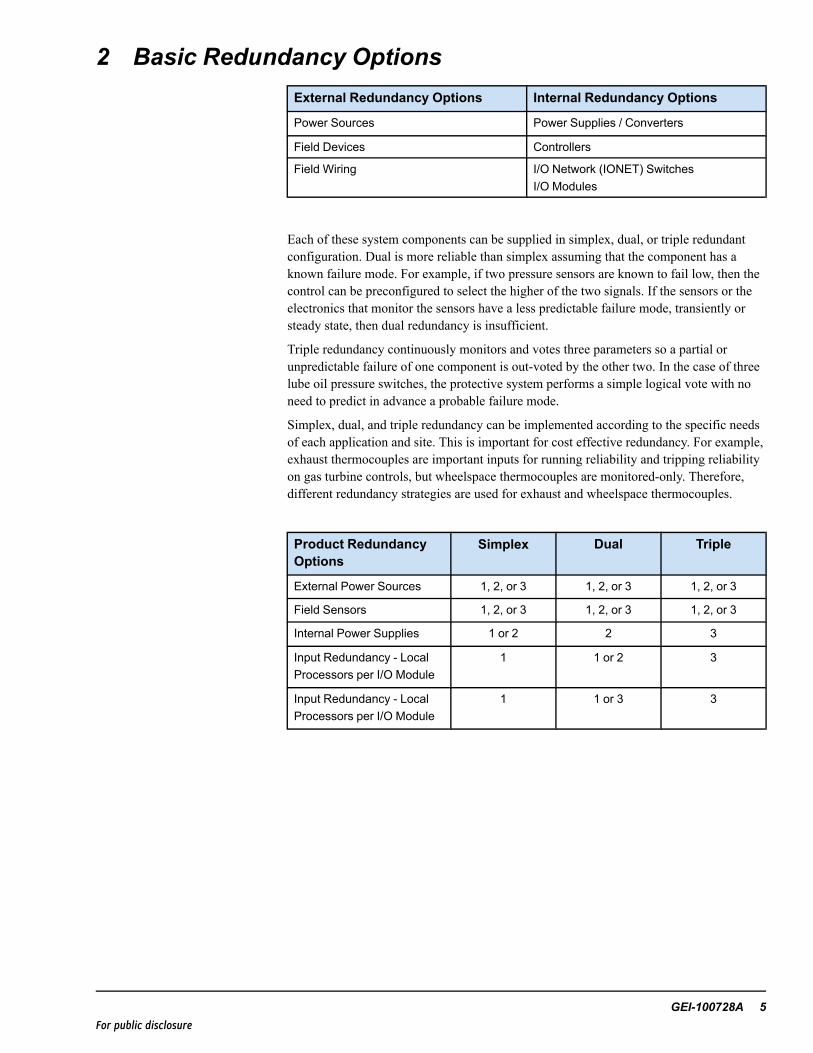
Typical Mark VIe Architecture
3 Power RedundancyThe terminology for power sources, supplies, and converters is often confused. Anexternal power source is provided for the electronics, which have internal power suppliesthat convert the source voltage to low-level regulated busses for circuit boards. In manycases, there is also a wetting voltage required for contact inputs, analog inputs, and powerfeeds for field solenoids that are powered from the control.
The control system accepts one, or redundant, 24 V dc, 125 V dc, and 115/230 Vacsources that can be mixed in any combination. Internal power supplies convert the sourcevoltage to 28 V dc for the controller, IONet switches, and the distributed I/O modules.Internal supplies are normally non-redundant for simplex control systems, but can beprovided as dual redundant, if required. Dual redundant power supplies are provided fordual redundant control systems, and dual/triple redundant power supplies are provided fortriple redundant controls systems. An exception is remote I/O panels with non-criticalI/O. These panels normally have a single power supply regardless of whether thecontrollers are redundant or non-redundant. But, they can be supplied in redundant pairstoo, if required. Additional redundancy options are available.
6 GEI-100728A Mark VIe Redundancy – Overview of System OptionsFor public disclosure
Internal Power Converters Create 28V dc for:- Controllers- IONET Switches- I/O Modules
Field Power Sources- 1 Source- 2 Sources- 3 Sources
24V dc
125V dc
115/230V ac
28V dc
Controllers
Switches
I/O Modules
Power for Electronics
Field Power Sources- 1 Source- 2 Sources- 3 Sources
24V dc
48V dc
125V dc
Wetting Voltage
Contact Inputs
Transducers
Solenoids
Power for Field Devices
115/230V ac
Wetting Voltage from Field
Redundant SuppliesAC to 24Vdc
Redundant SuppliesAC to 28Vdc
Diode High-Selects
Power Sources, Converters, and Supplies
Different power sources can be provided for the internal electronics and the wettingvoltage for contact inputs, transducers, and solenoid power. For example, redundant 230Vac sources can be converted to 28 V dc for the internal electronics. If 125 V dc wettingvoltage is needed for contact inputs or field solenoids, it can be provided directly from thestation battery or from redundant 230 Vac to 125 V dc converters in the control.
Diagnostics monitor power sources and power supplies for fault detection and to enableonline repair.
GEI-100728A 7For public disclosure
4 ControllerA single-board controller is the heart of the system. It includes the main processor andthree Ethernet drivers for communications with networked I/O and two additionalEthernet drivers for the control network. One, two, or three controllers are provided asrequired for redundancy.
Some suppliers support redundant processors and communication boards in a commonrack with a split backplane for improved fault tolerance. Another form of redundancy hastwo controllers with two processors in each of the two controllers in a quad configuration.If one of the processors has a partial failure, there will be a discrepancy between the datafrom the two processors on one board, and the other board takes control.
A key evaluation point for any redundant control system is the failover time from onecontroller to the other. If one controller normally drives the control valve and the other ison standby in a hot-backup configuration, then there is a finite time for the backup todetermine that the main controller has failed so that it can take over. This failover time iscritical to the process.
Another method is to have both controllers continuously reading inputs, runningapplication software, and providing outputs to the control valves and relays, so there is nofailover time between controllers. Somewhere between the controllers and the controlvalves / relays a decision is made to follow the commands from one controller or theother. This decision point is a critical item in determining failover time, failure mode, andoverall system fault tolerance.
8 GEI-100728A Mark VIe Redundancy – Overview of System OptionsFor public disclosure
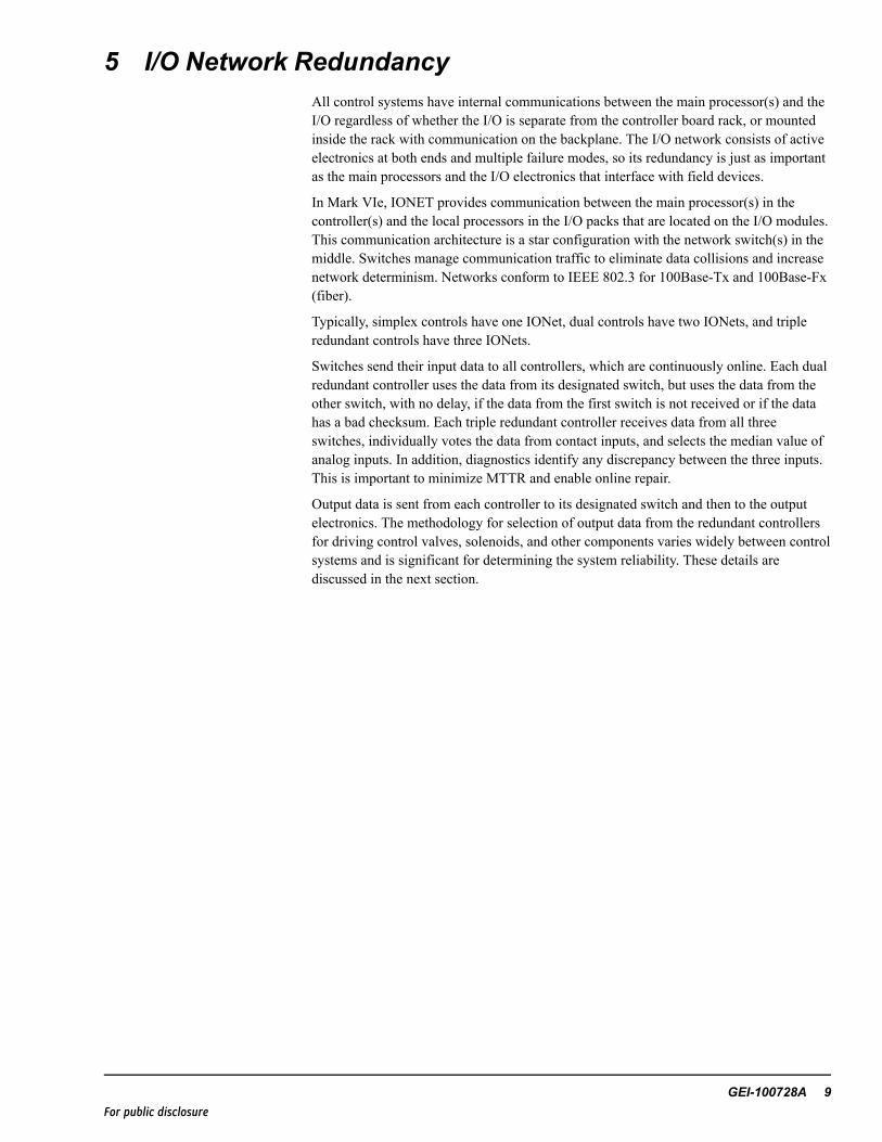
5 I/O Network RedundancyAll control systems have internal communications between the main processor(s) and theI/O regardless of whether the I/O is separate from the controller board rack, or mountedinside the rack with communication on the backplane. The I/O network consists of activeelectronics at both ends and multiple failure modes, so its redundancy is just as importantas the main processors and the I/O electronics that interface with field devices.
In Mark VIe, IONET provides communication between the main processor(s) in thecontroller(s) and the local processors in the I/O packs that are located on the I/O modules.This communication architecture is a star configuration with the network switch(s) in themiddle. Switches manage communication traffic to eliminate data collisions and increasenetwork determinism. Networks conform to IEEE 802.3 for 100Base-Tx and 100Base-Fx(fiber).
Typically, simplex controls have one IONet, dual controls have two IONets, and tripleredundant controls have three IONets.
Switches send their input data to all controllers, which are continuously online. Each dualredundant controller uses the data from its designated switch, but uses the data from theother switch, with no delay, if the data from the first switch is not received or if the datahas a bad checksum. Each triple redundant controller receives data from all threeswitches, individually votes the data from contact inputs, and selects the median value ofanalog inputs. In addition, diagnostics identify any discrepancy between the three inputs.This is important to minimize MTTR and enable online repair.
Output data is sent from each controller to its designated switch and then to the outputelectronics. The methodology for selection of output data from the redundant controllersfor driving control valves, solenoids, and other components varies widely between controlsystems and is significant for determining the system reliability. These details arediscussed in the next section.
GEI-100728A 9For public disclosure
6 I/O Redundancy
6.1 Dual RedundantA basic dual redundant control has a sensor connected to an I/O module with one I/Opack that communicates data to two IONET switches (Refer to the following figure).Each IONET switch transmits the data to both controllers, which are online and runningthe same application software.
This configuration has the advantage of network and controller redundancy but noredundancy for the sensor or I/O module. Another option is adding a second sensor and asecond I/O module. This increases the fault tolerance and the ability to perform onlinerepair at least to the module and possibly to the sensor assuming that the sensor can bereplaced while the process is running. Note that online repair is at the I/O pack level.Therefore, replacement of I/O has minimal impact on monitoring and control of theoverall control system. An extension of this is to add a third sensor whose value can bevoted in the application software. This is an example of triple redundant sensors and I/Omodules with dual networks and dual controllers.
An example of this configuration is in a heat recovery steam generator (HRSG) controlthat has minimal critical I/O except for the drum level. Triple redundant sensors can beadded just for the drum level control to optimize system availability for the least cost.
One Sensor & Dual Controllers
Sensor A
+24Vdc
Supports on-line repair of IONET switches and controllers
Designated Controller
1. Provides the master clock2. Supplies initialization data3. Provides recovery data4. Receives external commands5. Creates process alarms
10 GEI-100728A Mark VIe Redundancy – Overview of System OptionsFor public disclosure
Two Sensors & Dual Controllers
Option: communication to second IONET port
Sensor A
+24Vdc
Sensor B
+24Vdc
Sensor A
+24Vdc
Sensor B
+24Vdc
Sensor C
+24Vdc
On-line replacement of I/O Packs & auto reconfiguration
Sensor diagnostics enable on-line repair assuming on-line process access
Analog – Median selectContacts – Logical voteDisagreement diagnosticsCan be mixed with dual & simplex inputs
Three Sensors & Dual Controllers
Three sensors are beneficial when the sensor has an unpredictable failure mode .
Designated Controller1. Provides the master clock2. Supplies initialization data3. Provides recovery data4. Receives external commands5. Creates process alarms
GEI-100728A 11For public disclosure
Data outputs from dual redundant controllers are normally implemented with eachcontroller sending its signal to its switch and each switch forwarding the signal to one ofthe two ports on an I/O pack on an I/O module. The pack uses the first healthy referencethat it sees and continues to use it until it is not available or the pack determines that thesignal is unhealthy. This results in a transfer to the second reference with no latency indriving outputs. In the unlikely event that an output pack loses communication with bothIONETs, it defaults to one of three pre-configured states: 0 = Power Down State,1 = Preset Value State, 2 = Last Value State.
Process Outputs
Dual Outputs to One I/O Pack
Process Outputs
Dual Outputs to Three I/O Packs
I/O Pack uses the first healthy reference that it sees In the unlikely loss of both channels, it defaults to:0 = Power-down state1 = Preset value state2 = Last value state
Basic forms of output module:Relays – Voting occurs at a relay driverRelays – Voting occurs with 2/3 contact votingAnalog – Median select with a passive, current-sharing circuit Analog – Voting occurs with a 3-coil servo
12 GEI-100728A Mark VIe Redundancy – Overview of System OptionsFor public disclosure
If redundancy is required for the I/O pack, three (not two) I/O packs can be mounted onthe I/O module to provide a reliable two-out-of-three reference for each drivencomponent. For general-purpose 4 - 20 mA outputs, the three I/O packs drive a common,passive, current-sharing circuit on the I/O module that produces a single 4 - 20 mAoutput. This is the median signal from the three I/O packs. There are also 0 – 200 mAoutputs available to drive valve positioners.
A customized (application-specific) implementation of current outputs is used for servos.These outputs are similar to the 4 - 20 mA outputs and can have one or three I/O packs,for redundancy, that drive three bi-polar servo coils on the same control valve actuator.The advantage of three coil servos is that there is no single component in the electronicsthat selects between the redundant valve commands and is vulnerable to failure.
Relay outputs are available in three redundancy levels:
• Level 1 provides dual redundant controllers, IONET switches, and Ethernet ports ona common I/O pack, which controls a relay driver and a relay.
• Level 2 also provides dual redundant controllers and IONET switches, but extendsthe redundancy to three redundant I/O packs, which are voted by a common relaydriver feeding a relay.
• Level 3 extends the voting to three sets of mechanical relays, which vote with theircontacts. This is available with 36 relays voting to create 12 contact outputs that areavailable as form “A” (normally open) and form “B (normally closed) configuration.Application-specific versions of this are available for interface with hydraulic tripsolenoids on turbines, which vary in quantity, rating, and specific implementation
Many other factors should be considered when choosing the proper contact output circuitfor reliability. For example, magnetic relays and solid-state outputs are available.Magnetic relays have form “C” contacts (1 open and 1 closed with a common point). Thisallows preplanning for the most common failure mode, de- energize, for a magnetic relay.In this scenario, a normally-closed contact can energize a Motor Control Center starter,which is not available on solid-state outputs. If the starter is for the lube oil pump, then itprobably warrants the highest level of redundancy. However, if there is an emergencylube oil pump to back-up the auxiliary pump, then there is less need for redundantelectronics. Other considerations are whether the relays are sealed for hazardouslocations, leakage current in the case of solid-state relays, suppression for solenoidapplications and so forth.
GEI-100728A 13For public disclosure
6.2 Triple RedundantControllers, power supplies, networks, and I/O are physically separate, which is the originof the term triple modular redundant (TMR) that is often used when describing the controlsystem. Triple redundant controls offer a higher degree of fault tolerance than dualredundant controls. The primary advantages are the ability to ride-through a soft (partial)failure of a controller, network, or I/O component with an unexpected failure mode, andthe ability to identify the origin of the fault with greater precision.
Since triple redundant controls are applied in a wide variety of applications, the I/O isflexible and can be implemented with single, dual, or triple sensors that are connected toone or multiple I/O modules. Obviously, triple redundant sensors are more fault tolerantthan dual redundant or single sensors, but there is also a tradeoff between the cost ofredundant sensors and the historical reliability of a particular sensor type for a specificapplication. Identical application software in each controller read sensor inputs, anddiagnostics compares the data. Discrepancies are reported as system / process alarms.
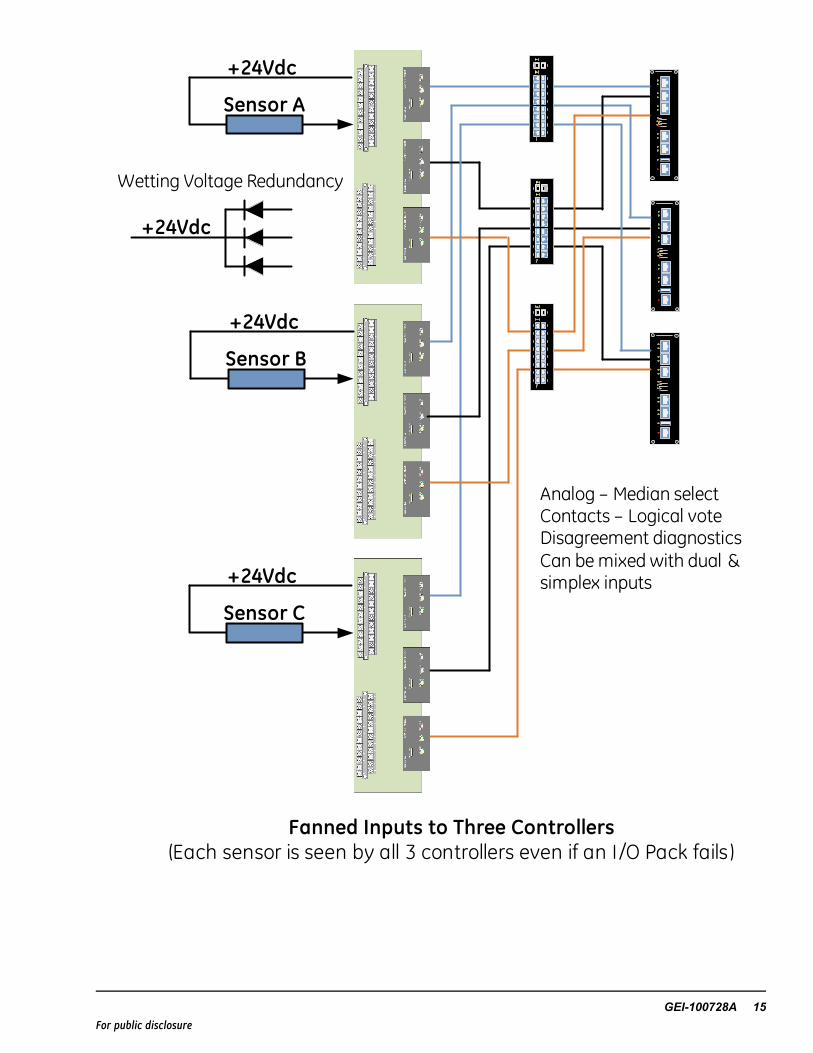
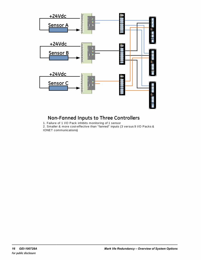
Each sensor can be transmitted in parallel to the three IONETs (fanned) or transmittedindividually. Fanned inputs are transmitted on the IONETwith three I/O packs on the I/Omodule. Therefore, a failure of an I/O pack does not inhibit any controller from seeing allof the sensors. In addition, any disagreement between the data values for the same sensorin the three controllers is identified as an internal diagnostic fault. Non-fanned inputshave less electronics (lower MTBF) but also less diagnostic precision, because there isonly one I/O pack per sensor. Since the precision of the diagnostics impacts the MTTR, italso impacts the availability of the control system and the process.
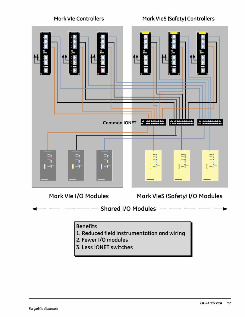
The Mark VIe is also available as a SIL-3 capable safety controller, Mark VIeS, insimplex, dual, and triple redundant configurations. Both systems share commonarchitectures, configuration and diagnostic software tools, and can share input data fromI/O modules on a common IONET to simplify operations and maintenance. When sharingI/O, the controllers from the Mark VIe and Mark VIeS can read inputs from all I/Omodules, but write outputs only to their own I/O modules.
14 GEI-100728A Mark VIe Redundancy – Overview of System OptionsFor public disclosure
Sensor A
+24Vdc
Sensor B
+24Vdc
Sensor C
+24Vdc
Analog – Median selectContacts – Logical voteDisagreement diagnosticsCan be mixed with dual & simplex inputs
+24Vdc
Wetting Voltage Redundancy
Fanned Inputs to Three Controllers(Each sensor is seen by all 3 controllers even if an I/O Pack fails )
GEI-100728A 15For public disclosure
Sensor A
+24Vdc
Sensor B
+24Vdc
Sensor C
+24Vdc
Non-Fanned Inputs to Three Controllers1. Failure of 1 I/O Pack inhibits monitoring of 1 sensor2. Smaller & more cost-effective than “fanned” inputs (3 versus 9 I/O Packs & IONET communications)
16 GEI-100728A Mark VIe Redundancy – Overview of System OptionsFor public disclosure
Mark VIe Controllers Mark VIeS (Safety) Controllers
Mark VIe I/O Modules Mark VIeS (Safety) I/O Modules
Common IONET
Shared I/O Modules
Benefits:1. Reduced field instrumentation and wiring2. Fewer I/O modules3. Less IONET switches
GEI-100728A 17For public disclosure
Non-critical data that is being used for non-essential monitoring is usually implementedwithout redundancy. Redundant and non-redundant I/O coexists in most control systems.
The overall scheme of software voting, diagnostics, and online repair capability is knownas Software Implemented Fault Tolerance (SIFT). Its significance is that applicationsoftware in each of the three control sections performs the voting rather than a singlehardware voter that would compromise reliability by introducing a potential single pointfailure.
Outputs Driven from Common I/O Module
Voting at I/O Module
Basic forms of output module:Relays – Voting occurs at a relay driverRelays – Voting occurs with 2/3 contact votingAnalog – Median select with a passive, current-sharing circuit Analog – Voting occurs with a 3-coil servo
18 GEI-100728A Mark VIe Redundancy – Overview of System OptionsFor public disclosure
Extended Voting at Field Device(Example: 3 Coil Servo Valve Actuator)
Typical nuclear configuration
Valve Regulator
Valve Ref.
Valve Regulator
Valve Ref.
Valve Regulator
Valve Ref.
������
������
������
3 CoilServo Valve
Excitation
HydraulicCylinder
�����
Position Feedback
Position Feedback
Excitation
Position Feedback
Excitation
GEI-100728A 19For public disclosure
A good redundant control system has a solution for handling faults all the way to thecontrol valves and trip solenoids. Any compromise in fault tolerance prior to the finaloutput device seriously degrades the MTBFO of the entire system. Therefore, outputs arevoted in hardware and preferably as close as possible to the final output device that isbeing controlled.
An example of extending the voting to the field component is driving three-coil servovalve actuators. The flux from the three coils moves the valve, and LVDTs provideposition feedback to the valve regulators that are located in each I/O pack. In normaloperation, each current driver is slightly off null, and in the event of a fault, the remainingtwo current drivers compensate for the loss. This is hardware voting of the current outputsat the control valves.
Standard GE triple redundant control systems are highly fault tolerant but not devoid ofsingle point failures. As an example, I/O packs are mounted on I/O modules with passivecomponents and high corresponding MTBF. Some applications, such as nuclear, requireno single point failures. Requirements for no single point failures must be evaluated on acase-by-case basis to determine the best way to approach this from the system level. Thepreceding figure displays a variation of outputs to three coil servos where each coil isdriven from a separate I/O module. This eliminates single point failures from this circuitand demonstrates the flexibility of the controls to meet this objective. However, it alsodemonstrates the additional size and cost that may be required to eliminate single pointfailures when field devices are considered, as they should be.
Similarly, a triple redundant control system uses the contacts from three relays to voteeach output to each hydraulic trip solenoid. In some high-availability applications such asnuclear, the voting is extended to dual TMR hydraulic trip manifolds that support on-linerepair.
DN1600N Hydraulic Trip Assembly
• (2) sets of 2-out-of-3 hydraulic trip circuits A & B
• Parallel operation with both normally operating
• Enables isolation and maintenance of 1 during normaloperation
• Remote control on-line test capability: 1 of 3 elements ofA & B
• A & B joined with shut-off continuous flow transfer valveassembly
• Fully instrumented with trip and reset positiontransducers
20 GEI-100728A Mark VIe Redundancy – Overview of System OptionsFor public disclosure
Protection Redundancy, Simplex and Dual Redundant Systems
Turbine control applications have primary and backup trip protection for trippingreliability. The controller and its corresponding I/O control, protect, and monitor theturbine. Primary protection includes a full set of all trip functions, and backup protectionincludes a small subset of the protection functions to backup the primary. Typical backupfunctions include emergency overspeed protection, manual- emergency trip, and synchcheck protection for generator drives. Additional backup functions can be added asrequired for specific applications or industry code requirements.
Backup protection is completely separate and independent from the primary protection,including separate power supplies, processors, and I/O. In addition, the hardware andapplication software are sufficiently dissimilar from the primary to dramatically reducethe probability of common mode failures between the primary and backup protection dueto common technology. Backup protection is frequently supplied as triple redundantregardless of the redundancy configuration of the primary controllers.
Overspeed with Accel/DecelBackup Synch CheckManual Trip
Hydraulic Trip Solenoids
Control Valves
MEDRST
MEDXYZ
AND Run
MEDRST
MEDXYZ
OR Trip
Protection Redundancy, Triple Redundant Systems
A key tripping reliability feature is cross-tripping. The primary and backup systemsinitiate a trip independently, but can also initiate a cross-trip for additional trippingredundancy. For example, a trip that originates in the backup protection can be sent to theprimary protection to close the control valves and de-energize the trip solenoids from theprimary side. Another example, the backup protection monitors communications fromeach controller, so it can be configured to initiate a trip on behalf of the controllers.
Functionality for the backup protection system is application-specific and subject to thesafety requirements dictated by code and/or GE design practices for specific turbinetypes. In general, it complies with most industry standards. It is separate and independentfrom the primary protection, with more functionality than required by most codes. As anexample, ANSI/API-670 requirements for overspeed protection are written for an (one)independent, triple redundant system. The standard GE overspeed system for aheavy-duty gas turbine or a combined-cycle steam turbine consists of two triple redundantprotection systems with cross-tripping.
22 GEI-100728A Mark VIe Redundancy – Overview of System OptionsFor public disclosure
8 Digital Bus ReliabilityIn addition to the variety of classic Mark VIe I/O modules, additional I/O modules areavailable for digital busses such as FOUNDATION Fieldbus™, PROFIBUS®, HART®, andCANopen®. These modules share a common design with other I/O modules consisting ofa local processor that communicates on the IONET to switches and then to the controllers.Similarly, they share a common ControlST* software suite with ToolboxST*configuration and diagnostic tools. It is beyond the scope of this paper to review theredundancy options for each specific digital bus. However, some basic principles areprovided for reference.
8.1 FOUNDATION FieldbusFor reliability, two linking devices (I/O modules) can be connected with a RS-232C nullmodem cable to form one logical linking device (a redundant set) in a primary / secondaryconfiguration. Both linking devices are connected to the same H1 field devices andIONET. If the primary device were to fail, the secondary device would provide a backup.The original primary could then be replaced and automatically reconfigured to match thenew primary device.
For a typical application with redundant controllers, there is a primary controller (thedesignated controller) and a secondary controller. Therefore, the primary linking device isthe one connected to the primary controller. Less common are applications with a singlecontroller and redundant linking devices. In this scenario, the first linking device to bepowered becomes the primary.
8.2 PROFIBUS DP-V0 and DP-V1, Class 1 MastersThe I/O module can be configured for three types of redundancy:
• One I/O module with one I/O network
• One I/O module with dual I/O networks
• HotBackup I/O modules with dual I/O networks
The active master communicates with the slaves while the backup master is in standbymode. The backup is ready to automatically switchover in less than 200 ms if any of thefollowing conditions occur:
• All master/slave communication is lost
• Master/controller communication is lost on both I/O
• The master is powered down
8.3 HART CommunicationsHighway Addressable Remote Transducer (HART) communications provide diagnosticsand remote communications to smart field devices with standard 4-20 mAwiring. EachI/O module can communicate with dual redundant IONET switches.
8.4 CANopen CommunicationsThe protocol specifications are developed and maintained by the Controller Area Network(CAN) in Automation standards organization comprising. Each I/O module cancommunicate with dual redundant IONET switch.
GEI-100728A 23For public disclosure
9 Relative ReliabilityThe contribution of redundancy to improving reliability varies greatly betweenapplications, but some basic guidelines are useful. Field devices and wiring are the majorcause of forced outages. Therefore, adding redundant electronics to a system with historicfield device problems accomplishes little. Improving the quality of the devices and addingredundancy will help.
Two surveys of GE turbine control installations indicated that field devices and wiringcontributed to 57% and 69% of forced outages. Redundancy was applied to both the fielddevices and the electronics at these sites to mitigate the overall control system forcedoutages.
Causes of Forced Outages
Field Devices & Wiring 57% Electronics 31%
Survey Diff.12%
Relative MTBFO of Electronics Only
1 1.3 13 15Dual Controllers, Supplies, Switches
Simplex, Non-redundant
Dual with Redundant I /O
FullTriple
Redundant
Dual Redundant Triple
Relative Contributions to Reliability and MTBFO
Adding redundancy to the electronics can improve the MTBFO of the electronics byapproximately 15:1 from a completely non-redundant control to a fully triple redundantcontrol. Between these extremes are redundancy options that can be added to simplex anddual redundant controls that add to their fault tolerance, as previously discussed. Theoption with the biggest impact on the reliability of the electronics is redundant I/O.Control systems with large I/O quantities have a significant amount of electronics (I/Oprocessors, A/D converters, relays, and so on) that are in the critical path for running andstarting reliability. Selective addition of redundancy to these systems can have a dramaticimpact on the reliability of the electronics.
24 GEI-100728A Mark VIe Redundancy – Overview of System OptionsFor public disclosure