28
+ - MARSURF MARSURF XC 2 / XC 20 — MARWIN PC-BASED STATIONARY CONTOUR MEASURING STATIONS
| Date post: | 08-Dec-2015 |
| Category: |
Documents |
| Upload: | sorin-ovidiu |
| View: | 310 times |
| Download: | 2 times |
+-
MARSURF MARSURF XC 2 / XC 20 — MARWIN
PC-BASED STATIONARY CONTOUR MEASUR ING STATIONS
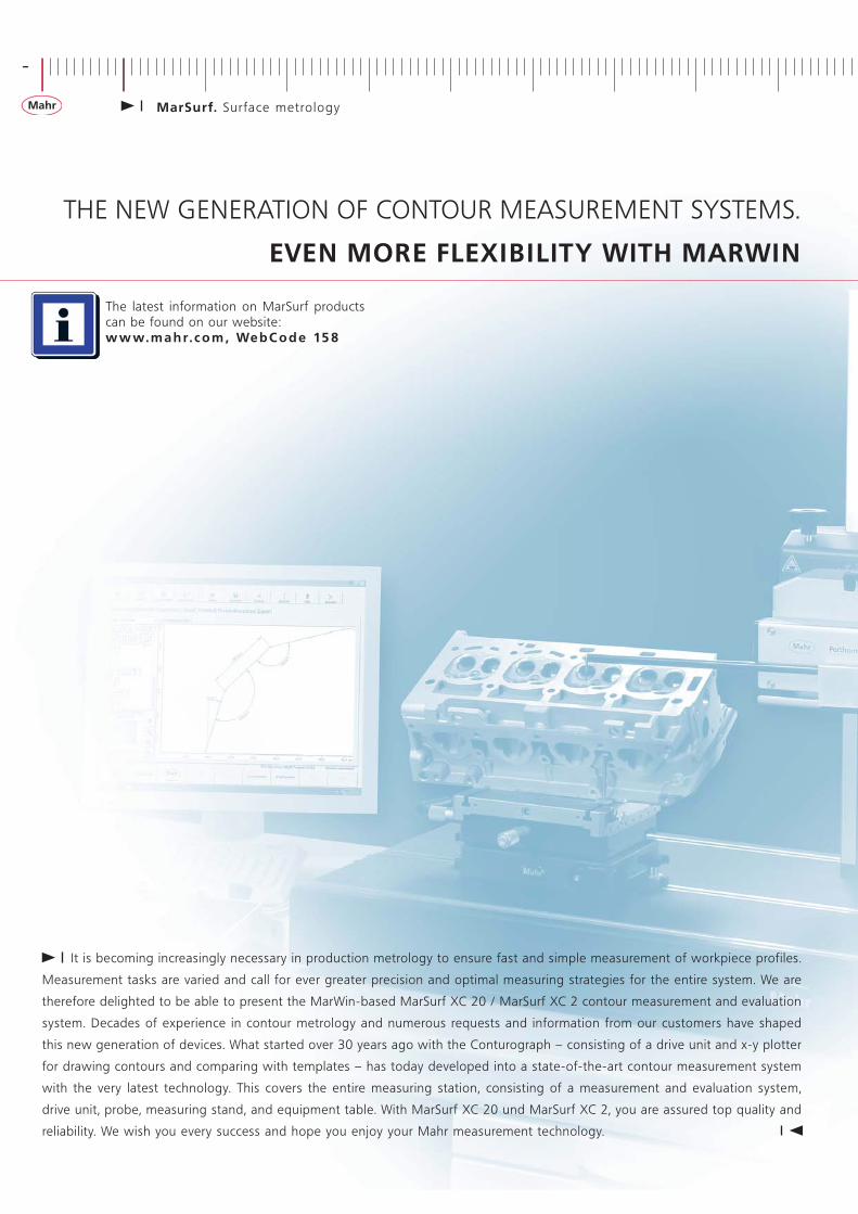
THE NEW GENERATION OF CONTOUR MEASUREMENT SYSTEMS.
EVEN MORE FLEXIBILITY WITH MARWIN
It is becoming increasingly necessary in production metrology to ensure fast and simple measurement of workpiece profiles.
Measurement tasks are varied and call for ever greater precision and optimal measuring strategies for the entire system. We are
therefore delighted to be able to present the MarWin-based MarSurf XC 20 / MarSurf XC 2 contour measurement and evaluation
system. Decades of experience in contour metrology and numerous requests and information from our customers have shaped
this new generation of devices. What started over 30 years ago with the Conturograph – consisting of a drive unit and x-y plotter
for drawing contours and comparing with templates – has today developed into a state-of-the-art contour measurement system
with the very latest technology. This covers the entire measuring station, consisting of a measurement and evaluation system,
drive unit, probe, measuring stand, and equipment table. With MarSurf XC 20 und MarSurf XC 2, you are assured top quality and
reliability. We wish you every success and hope you enjoy your Mahr measurement technology.
The latest information on MarSurf products can be found on our website: w w w. m a h r. c o m , We b C o d e 15 8
-
MarSurf. Sur face metro logy
MarSurf XC 2 / XC 20
PC-based Stationary Contour Measuring Stations 4
MarSurf XC 2 5
MarSurf XC 20 8
MarSurf XC 20 CNC 12
MarSurf XCR 20 13
MarSurf LD 120 14
MarSurf XP 20 CNC 16
MarWin . Software 17
Cal ibration Software 21
MarSurf. Contour Probes and Stylus Tips 22
MarSurf. Twin Stylus 23
MarSurf. Stylus Tip Pass 24
MarSurf. Measuring Stands 25
Accessories 27
+
MarSurf. Sur face metro logy
-
4 MarSurf. Sur face metro logy
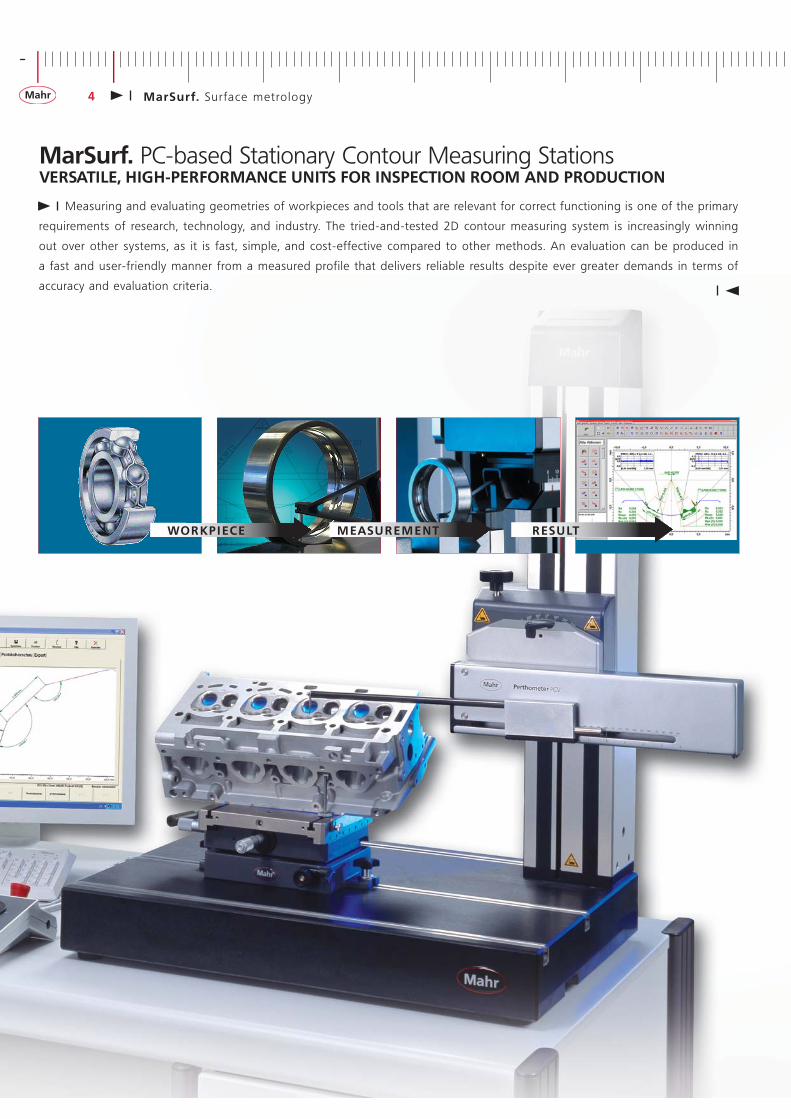
MarSurf. PC-based Stationary Contour Measuring StationsVERSATILE, HIGH-PERFORMANCE UNITS FOR INSPECTION ROOM AND PRODUCTION
Measuring and evaluating geometries of workpieces and tools that are relevant for correct functioning is one of the primary
requirements of research, technology, and industry. The tried-and-tested 2D contour measuring system is increasingly winning
out over other systems, as it is fast, simple, and cost-effective compared to other methods. An evaluation can be produced in
a fast and user-friendly manner from a measured profile that delivers reliable results despite ever greater demands in terms of
accuracy and evaluation criteria.
WOR KPI ECE M EASU R E M E NT R ESU LT
+
MarSurf. Sur face metro logy 5
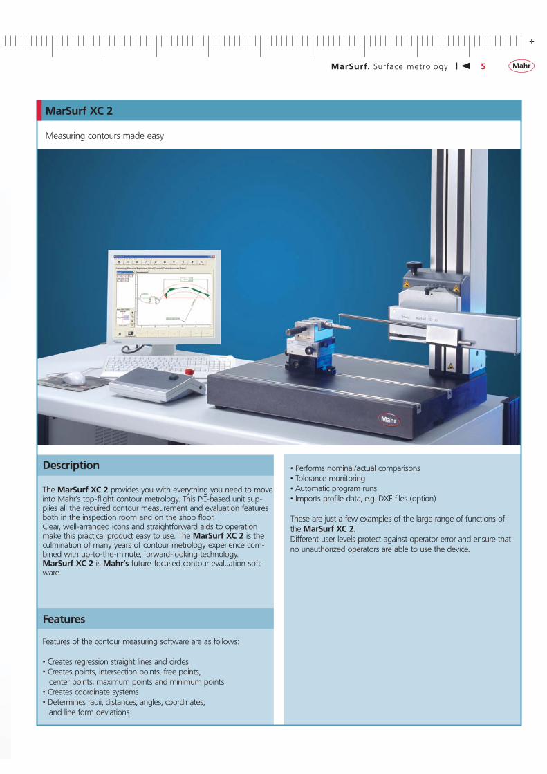
MarSurf XC 2
Measuring contours made easy
Features
• Performs nominal/actual comparisons• Tolerance monitoring• Automatic program runs• Imports profile data, e.g. DXF files (option)
These are just a few examples of the large range of functions of the MarSurf XC 2.Different user levels protect against operator error and ensure that no unauthorized operators are able to use the device.
Features of the contour measuring software are as follows:
• Creates regression straight lines and circles• Creates points, intersection points, free points, center points, maximum points and minimum points• Creates coordinate systems• Determines radii, distances, angles, coordinates, and line form deviations
Description
The MarSurf XC 2 provides you with everything you need to move into Mahr’s top-flight contour metrology. This PC-based unit sup-plies all the required contour measurement and evaluation features both in the inspection room and on the shop floor. Clear, well-arranged icons and straightforward aids to operation make this practical product easy to use. The MarSurf XC 2 is the culmination of many years of contour metrology experience com-bined with up-to-the-minute, forward-looking technology. MarSurf XC 2 is Mahr’s future-focused contour evaluation soft-ware.
-
6 MarSurf. Sur face metro logy
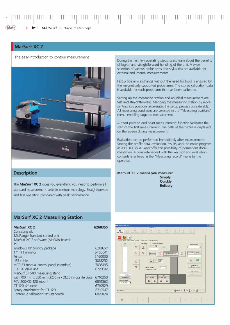
The MarSurf XC 2 gives you everything you need to perform all
standard measurement tasks in contour metrology. Straightforward
and fast operation combined with peak performance.
Description
MarSurf XC 2 Measuring Station
MarSurf XC 2 6268355Consisting of: MidRange Standard control unit MarSurf XC 2 software (MarWin-based) PCWindows XP country package 62682xx17“ TFT monitor 5460041Printer 5460030USB cable 3018232MCP 23 manual control panel (standard) 7035195CD 120 drive unit 6720812MarSurf ST 500 measuring stand with 700 mm x 550 mm (27.56 in x 21.65 in) granite plate 6710250PCV 200/CD 120 mount 6851362CT 120 XY table 6710529Rotary attachment for CT 120 6710547Contour 2 calibration set (standard) 6820124
During the first few operating steps, users learn about the benefits of logical and straightforward handling of the unit. A wide selection of various probe arms and stylus tips are available for external and internal measurements.
Fast probe arm exchange without the need for tools is ensured by the magnetically supported probe arms. The stored calibration data is available for each probe arm that has been calibrated.
Setting up the measuring station and an initial measurement are fast and straightforward. Mapping the measuring station by repre-senting axis positions accelerates the setup process considerably. All measuring conditions are selected in the "Measuring assistant“ menu, enabling targeted measurement.
A “Start point to end point measurement” function facilitates the start of the first measurement. The path of the profile is displayed on the screen during measurement.
Evaluation can be performed immediately after measurement. Storing the profile data, evaluation, results, and the entire program as a QE (Quick & Easy) offer the possibility of permanent docu-mentation. A complete record with the key text and evaluation contents is entered in the “Measuring record” menu by the operator.
MarSurf XC 2 means you measure: Simply Quickly Reliably
The easy introduction to contour measurement
MarSurf XC 2
+
MarSurf. Sur face metro logy 7
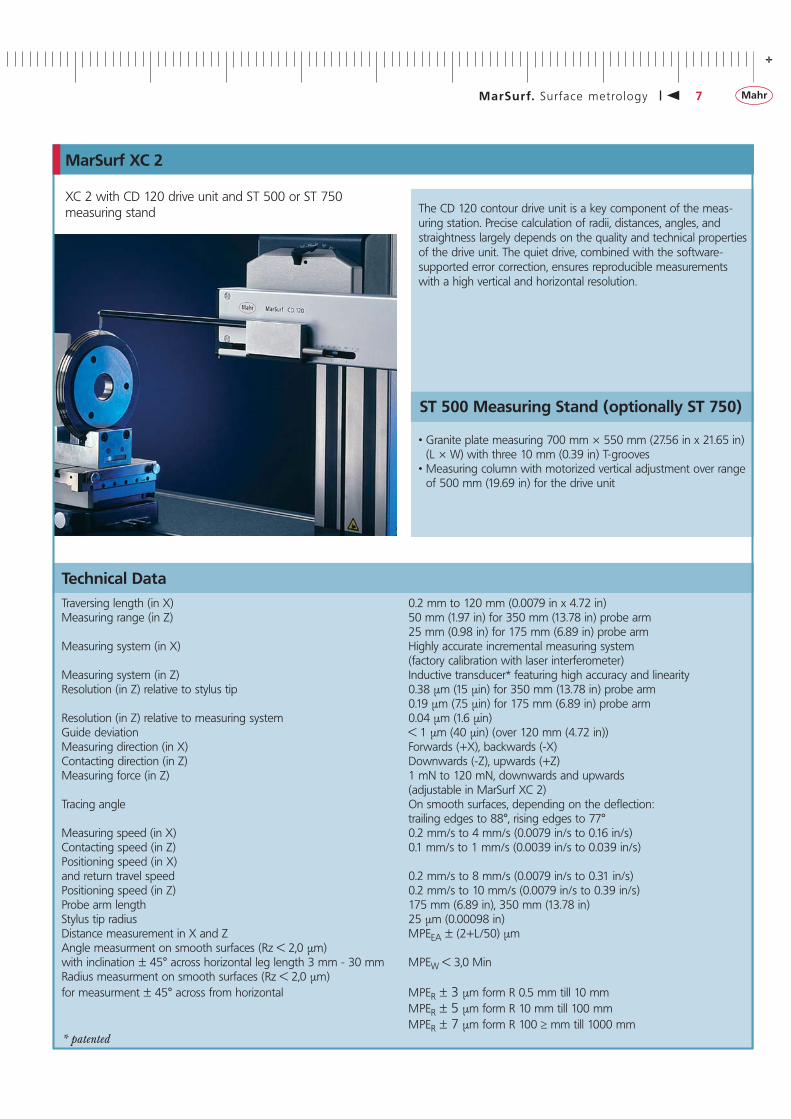
XC 2 with CD 120 drive unit and ST 500 or ST 750 measuring stand
Technical Data
ST 500 Measuring Stand (optionally ST 750)
MarSurf XC 2
• Granite plate measuring 700 mm × 550 mm (27.56 in x 21.65 in) (L × W) with three 10 mm (0.39 in) T-grooves
• Measuring column with motorized vertical adjustment over range of 500 mm (19.69 in) for the drive unit
The CD 120 contour drive unit is a key component of the meas-uring station. Precise calculation of radii, distances, angles, and straightness largely depends on the quality and technical properties of the drive unit. The quiet drive, combined with the software-supported error correction, ensures reproducible measurements with a high vertical and horizontal resolution.
Traversing length (in X) 0.2 mm to 120 mm (0.0079 in x 4.72 in)Measuring range (in Z) 50 mm (1.97 in) for 350 mm (13.78 in) probe arm 25 mm (0.98 in) for 175 mm (6.89 in) probe arm Measuring system (in X) Highly accurate incremental measuring system (factory calibration with laser interferometer)Measuring system (in Z) Inductive transducer* featuring high accuracy and linearityResolution (in Z) relative to stylus tip 0.38 μm (15 μin) for 350 mm (13.78 in) probe arm 0.19 μm (7.5 μin) for 175 mm (6.89 in) probe armResolution (in Z) relative to measuring system 0.04 μm (1.6 μin)Guide deviation < 1 μm (40 μin) (over 120 mm (4.72 in))Measuring direction (in X) Forwards (+X), backwards (-X)Contacting direction (in Z) Downwards (-Z), upwards (+Z)Measuring force (in Z) 1 mN to 120 mN, downwards and upwards (adjustable in MarSurf XC 2)Tracing angle On smooth surfaces, depending on the deflection: trailing edges to 88°, rising edges to 77°Measuring speed (in X) 0.2 mm/s to 4 mm/s (0.0079 in/s to 0.16 in/s)Contacting speed (in Z) 0.1 mm/s to 1 mm/s (0.0039 in/s to 0.039 in/s)Positioning speed (in X)and return travel speed 0.2 mm/s to 8 mm/s (0.0079 in/s to 0.31 in/s)Positioning speed (in Z) 0.2 mm/s to 10 mm/s (0.0079 in/s to 0.39 in/s)Probe arm length 175 mm (6.89 in), 350 mm (13.78 in)Stylus tip radius 25 μm (0.00098 in)Distance measurement in X and Z MPEEA ± (2+L/50) μmAngle measurment on smooth surfaces (Rz < 2,0 μm)with inclination ± 45° across horizontal leg length 3 mm - 30 mm MPEW < 3,0 MinRadius measurment on smooth surfaces (Rz < 2,0 μm) for measurment ± 45° across from horizontal MPER ± 3 μm form R 0.5 mm till 10 mm MPER ± 5 μm form R 10 mm till 100 mm MPER ± 7 μm form R 100 ≥ mm till 1000 mm* patented
-
8 MarSurf. Sur face metro logy
Traversing length 1 mm to 200 mm (0.039 in to 7.87 in) Measuring range (in Z) 50 mm (1.97 in)
The versatile probe arm and stylus tip range for various tasks also includes the twin stylus (see page 23), which, using multiple meas- urement, enables an upper and lower profile of a workpiece to be measured without changing the probe arm.
• Granite plate measuring 700 mm × 550 mm (27.56 in x 21.65 in) (L × W) with three 10 mm (0.39 in) T-grooves
• Measuring column with motorized vertical adjustment over range of 500 mm (19.69 in) for the drive unit
• Easily exchangeable mounts• The measuring stand incorporates a manual mechanical angle
adjuster for the drive unit
ST 500 Measuring Stand
Description
Features
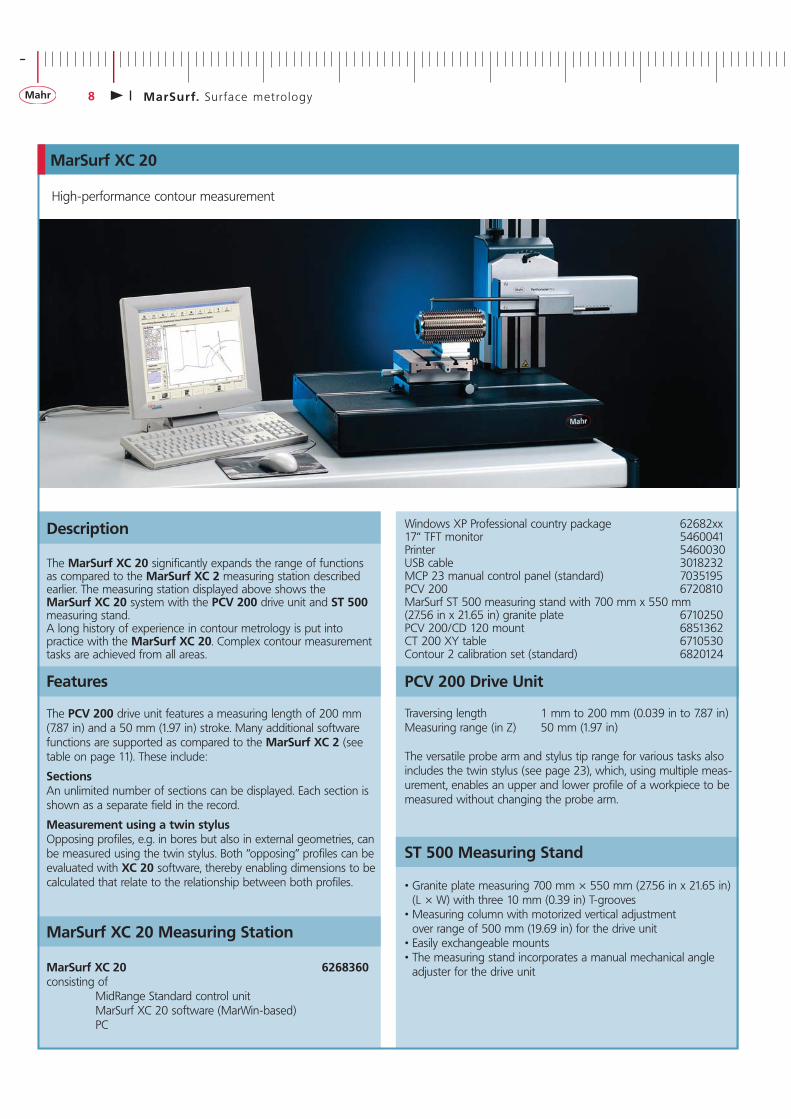
High-performance contour measurement
MarSurf XC 20 Measuring Station
Windows XP Professional country package 62682xx17“ TFT monitor 5460041Printer 5460030USB cable 3018232MCP 23 manual control panel (standard) 7035195PCV 200 6720810MarSurf ST 500 measuring stand with 700 mm x 550 mm (27.56 in x 21.65 in) granite plate 6710250PCV 200/CD 120 mount 6851362CT 200 XY table 6710530Contour 2 calibration set (standard) 6820124
PCV 200 Drive Unit
MarSurf XC 20
The MarSurf XC 20 significantly expands the range of functions as compared to the MarSurf XC 2 measuring station described earlier. The measuring station displayed above shows the MarSurf XC 20 system with the PCV 200 drive unit and ST 500 measuring stand.A long history of experience in contour metrology is put into practice with the MarSurf XC 20. Complex contour measurement tasks are achieved from all areas.
The PCV 200 drive unit features a measuring length of 200 mm (7.87 in) and a 50 mm (1.97 in) stroke. Many additional software functions are supported as compared to the MarSurf XC 2 (see table on page 11). These include:
SectionsAn unlimited number of sections can be displayed. Each section is shown as a separate field in the record.
Measurement using a twin stylusOpposing profiles, e.g. in bores but also in external geometries, can be measured using the twin stylus. Both “opposing” profiles can be evaluated with XC 20 software, thereby enabling dimensions to be calculated that relate to the relationship between both profiles.
MarSurf XC 20 6268360consisting of MidRange Standard control unit MarSurf XC 20 software (MarWin-based) PC
+
MarSurf. Sur face metro logy 9
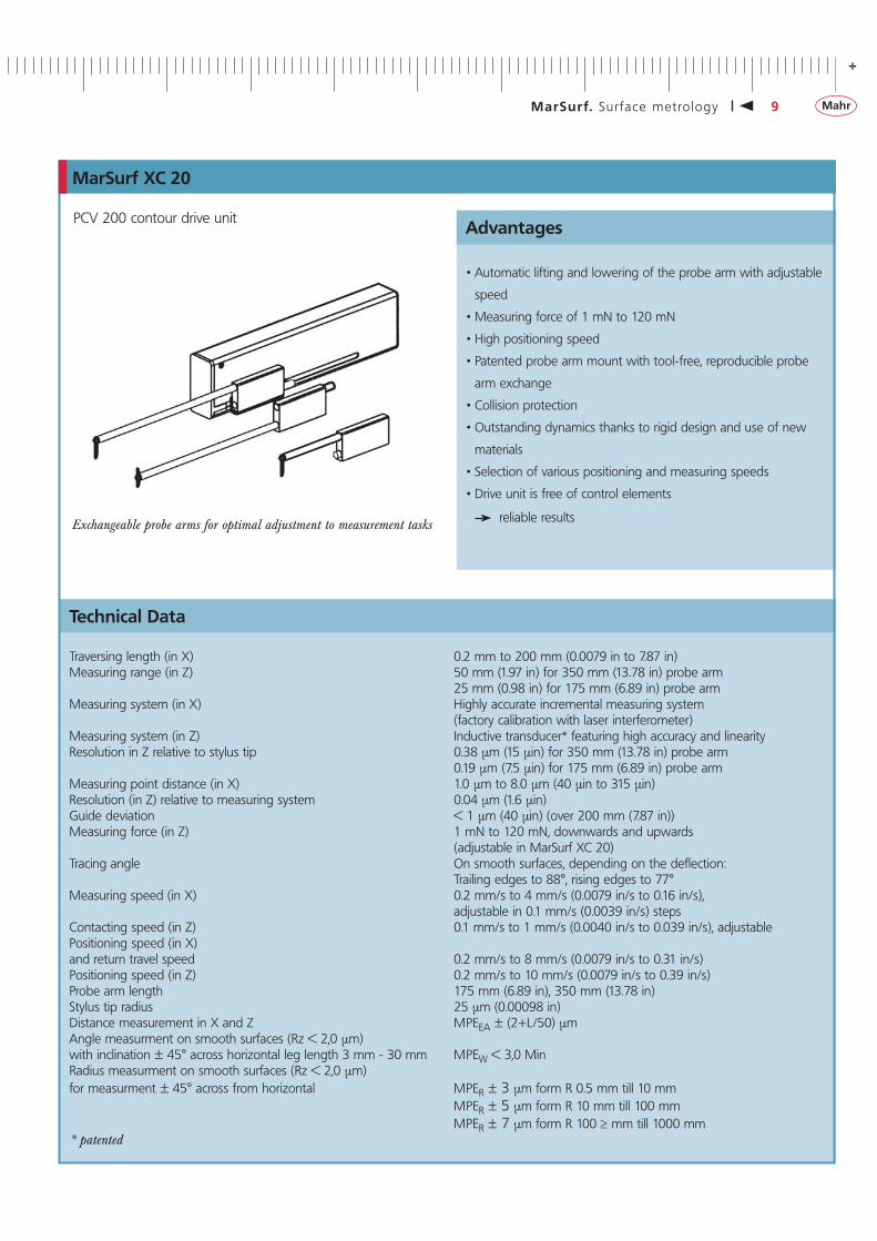
PCV 200 contour drive unit
Technical Data
• Automatic lifting and lowering of the probe arm with adjustable
speed
• Measuring force of 1 mN to 120 mN
• High positioning speed
• Patented probe arm mount with tool-free, reproducible probe
arm exchange
• Collision protection
• Outstanding dynamics thanks to rigid design and use of new
materials
• Selection of various positioning and measuring speeds
• Drive unit is free of control elements
reliable results
MarSurf XC 20
Advantages
Exchangeable probe arms for optimal adjustment to measurement tasks
Traversing length (in X) 0.2 mm to 200 mm (0.0079 in to 7.87 in)Measuring range (in Z) 50 mm (1.97 in) for 350 mm (13.78 in) probe arm 25 mm (0.98 in) for 175 mm (6.89 in) probe arm Measuring system (in X) Highly accurate incremental measuring system (factory calibration with laser interferometer)Measuring system (in Z) Inductive transducer* featuring high accuracy and linearityResolution in Z relative to stylus tip 0.38 μm (15 μin) for 350 mm (13.78 in) probe arm 0.19 μm (7.5 μin) for 175 mm (6.89 in) probe armMeasuring point distance (in X) 1.0 μm to 8.0 μm (40 μin to 315 μin)Resolution (in Z) relative to measuring system 0.04 μm (1.6 μin)Guide deviation < 1 μm (40 μin) (over 200 mm (7.87 in))Measuring force (in Z) 1 mN to 120 mN, downwards and upwards (adjustable in MarSurf XC 20)Tracing angle On smooth surfaces, depending on the deflection: Trailing edges to 88°, rising edges to 77°Measuring speed (in X) 0.2 mm/s to 4 mm/s (0.0079 in/s to 0.16 in/s), adjustable in 0.1 mm/s (0.0039 in/s) stepsContacting speed (in Z) 0.1 mm/s to 1 mm/s (0.0040 in/s to 0.039 in/s), adjustablePositioning speed (in X)and return travel speed 0.2 mm/s to 8 mm/s (0.0079 in/s to 0.31 in/s)Positioning speed (in Z) 0.2 mm/s to 10 mm/s (0.0079 in/s to 0.39 in/s)Probe arm length 175 mm (6.89 in), 350 mm (13.78 in)Stylus tip radius 25 μm (0.00098 in)Distance measurement in X and Z MPEEA ± (2+L/50) μmAngle measurment on smooth surfaces (Rz < 2,0 μm)with inclination ± 45° across horizontal leg length 3 mm - 30 mm MPEW < 3,0 MinRadius measurment on smooth surfaces (Rz < 2,0 μm) for measurment ± 45° across from horizontal MPER ± 3 μm form R 0.5 mm till 10 mm MPER ± 5 μm form R 10 mm till 100 mm MPER ± 7 μm form R 100 ≥ mm till 1000 mm* patented
-
10 MarSurf. Sur face metro logy
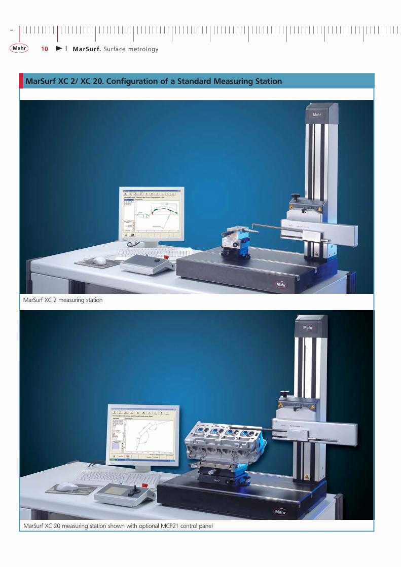
MarSurf XC 2/ XC 20. Configuration of a Standard Measuring Station
MarSurf XC 2 measuring station
MarSurf XC 20 measuring station shown with optional MCP21 control panel
+
MarSurf. Sur face metro logy 11
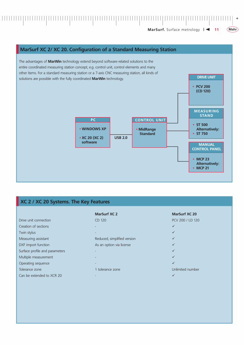
The advantages of MarWin technology extend beyond software-related solutions to the
entire coordinated measuring station concept, e.g. control unit, control elements and many
other items. For a standard measuring station or a 7-axis CNC measuring station, all kinds of
solutions are possible with the fully coordinated MarWin technology.
MarSurf XC 2/ XC 20. Configuration of a Standard Measuring Station
USB 2.0
• WINDOWS XP • XC 20 (XC 2) software
PC • MidRange Standard
CONTROL U N IT • ST 500 Alternatively: • ST 750
M EASU R I NG STAN D
• MCP 23 Alternatively: • MCP 21
MANUAL CONTROL PANEL
• PCV 200 (CD 120)
DRIVE UNIT
XC 2 / XC 20 Systems. The Key Features
MarSurf XC 2 MarSurf XC 20
Drive unit connection CD 120 PCV 200 / LD 120
Creation of sections -
Twin stylus -
Measuring assistant Reduced, simplified version
DXF import function As an option via license
Surface profile and parameters -
Multiple measurement -
Operating sequence -
Tolerance zone 1 tolerance zone Unlimited number
Can be extended to XCR 20 -
-
12 MarSurf. Sur face metro logy
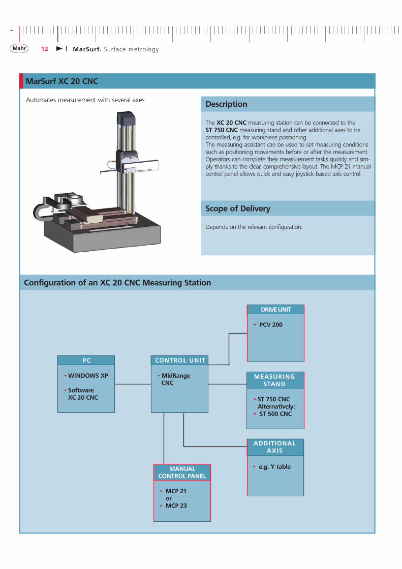
Automates measurement with several axes
Configuration of an XC 20 CNC Measuring Station
Description
Scope of Delivery
• WINDOWS XP • Software XC 20 CNC
PC • MidRange CNC
CONTROL U N IT
• ST 750 CNC Alternatively: • ST 500 CNC
M EASU R I NG STAN D
• PCV 200
DRIVE UNIT
• e.g. Y table
ADDITIONAL AXIS
• MCP 21 or • MCP 23
MANUAL CONTROL PANEL
MarSurf XC 20 CNC
Depends on the relevant configuration.
The XC 20 CNC measuring station can be connected to the ST 750 CNC measuring stand and other additional axes to be controlled, e.g. for workpiece positioning. The measuring assistant can be used to set measuring conditions such as positioning movements before or after the measurement. Operators can complete their measurement tasks quickly and sim-ply thanks to the clear, comprehensive layout. The MCP 21 manual control panel allows quick and easy joystick-based axis control.
+
MarSurf. Sur face metro logy 13
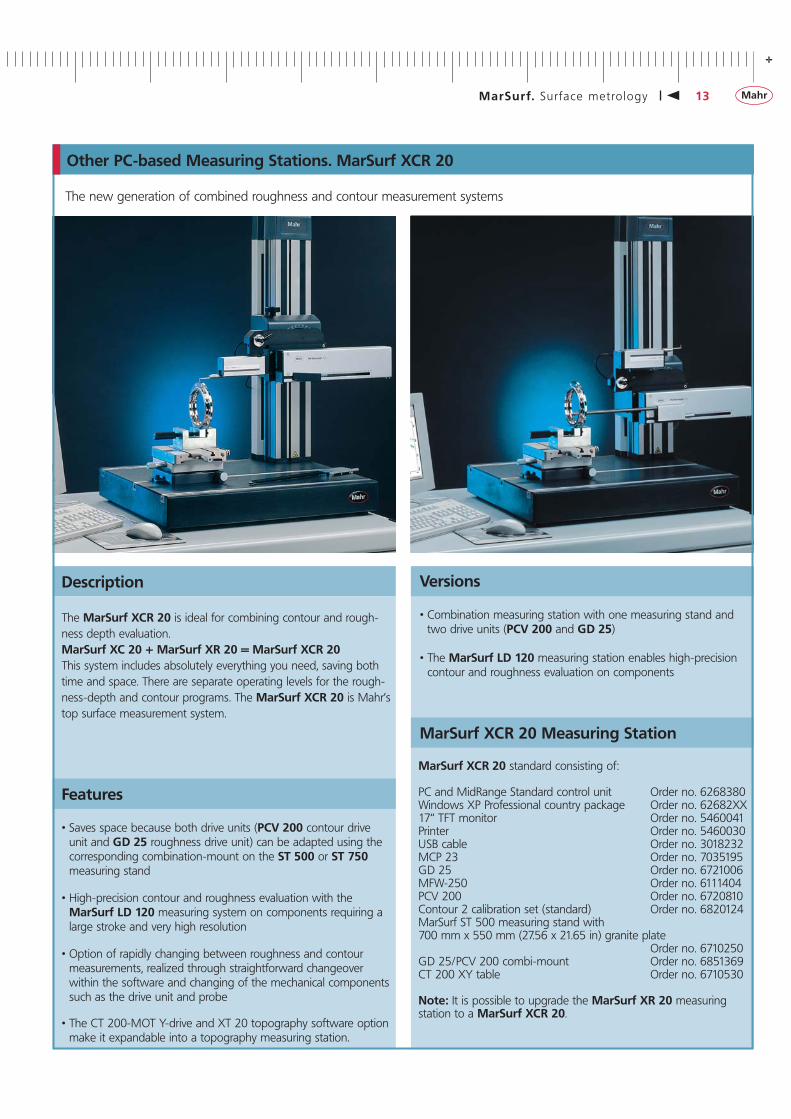
Description
Features
• Saves space because both drive units (PCV 200 contour drive unit and GD 25 roughness drive unit) can be adapted using the corresponding combination-mount on the ST 500 or ST 750 measuring stand
• High-precision contour and roughness evaluation with the MarSurf LD 120 measuring system on components requiring a large stroke and very high resolution
• Option of rapidly changing between roughness and contour measurements, realized through straightforward changeover within the software and changing of the mechanical components such as the drive unit and probe
• The CT 200-MOT Y-drive and XT 20 topography software option make it expandable into a topography measuring station.
The new generation of combined roughness and contour measurement systems
Versions
MarSurf XCR 20 Measuring Station
The MarSurf XCR 20 is ideal for combining contour and rough-ness depth evaluation.MarSurf XC 20 + MarSurf XR 20 = MarSurf XCR 20This system includes absolutely everything you need, saving both time and space. There are separate operating levels for the rough-ness-depth and contour programs. The MarSurf XCR 20 is Mahr’s top surface measurement system.
• Combination measuring station with one measuring stand and two drive units (PCV 200 and GD 25)
• The MarSurf LD 120 measuring station enables high-precision contour and roughness evaluation on components
MarSurf XCR 20 standard consisting of:
PC and MidRange Standard control unit Order no. 6268380Windows XP Professional country package Order no. 62682XX17“ TFT monitor Order no. 5460041Printer Order no. 5460030USB cable Order no. 3018232MCP 23 Order no. 7035195GD 25 Order no. 6721006MFW-250 Order no. 6111404PCV 200 Order no. 6720810Contour 2 calibration set (standard) Order no. 6820124MarSurf ST 500 measuring stand with 700 mm x 550 mm (27.56 x 21.65 in) granite plate Order no. 6710250GD 25/PCV 200 combi-mount Order no. 6851369CT 200 XY table Order no. 6710530
Note: It is possible to upgrade the MarSurf XR 20 measuringstation to a MarSurf XCR 20.
Other PC-based Measuring Stations. MarSurf XCR 20
-
14 MarSurf. Sur face metro logy
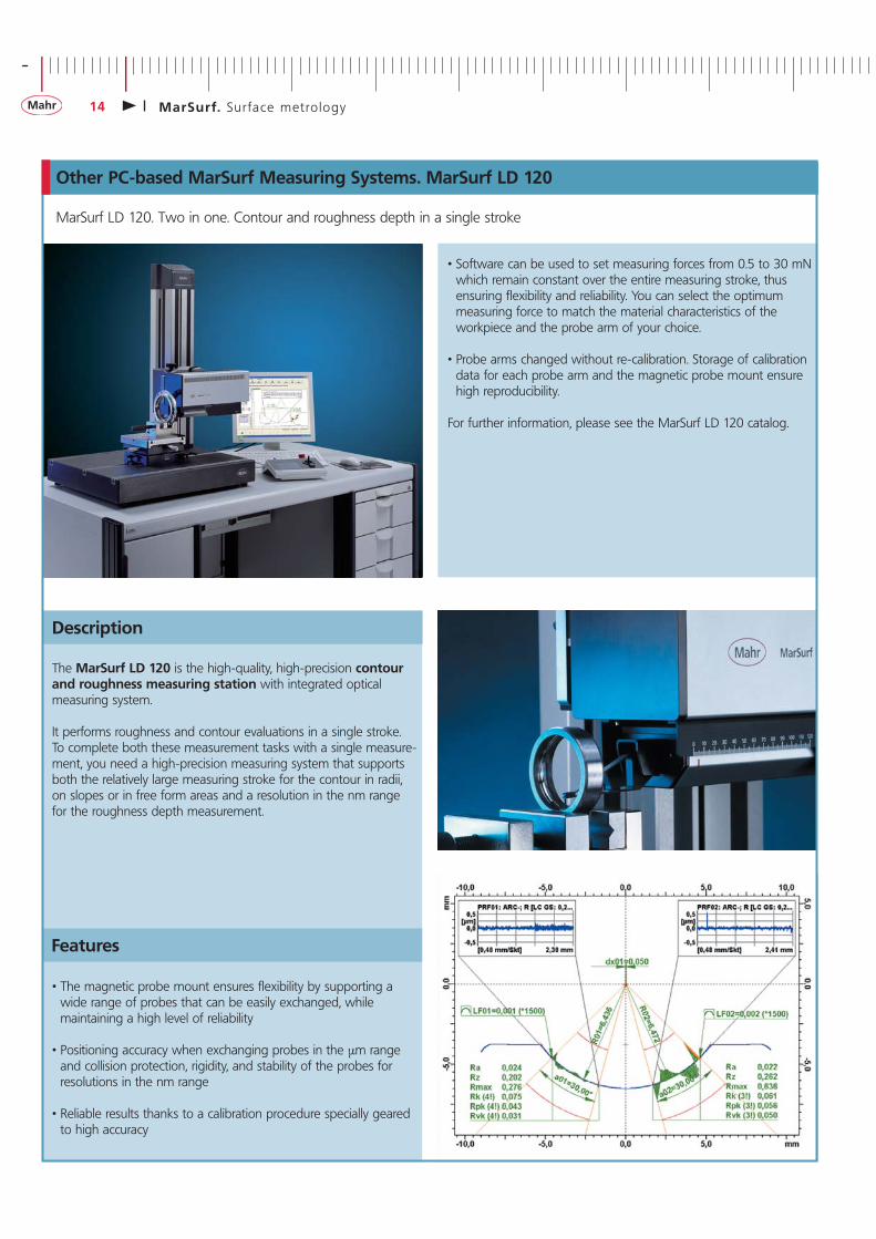
Description
Features
MarSurf LD 120. Two in one. Contour and roughness depth in a single stroke
Other PC-based MarSurf Measuring Systems. MarSurf LD 120
• Software can be used to set measuring forces from 0.5 to 30 mN which remain constant over the entire measuring stroke, thus ensuring flexibility and reliability. You can select the optimum measuring force to match the material characteristics of the workpiece and the probe arm of your choice.
• Probe arms changed without re-calibration. Storage of calibration data for each probe arm and the magnetic probe mount ensure high reproducibility.
For further information, please see the MarSurf LD 120 catalog.
• The magnetic probe mount ensures flexibility by supporting a wide range of probes that can be easily exchanged, while maintaining a high level of reliability
• Positioning accuracy when exchanging probes in the μm range and collision protection, rigidity, and stability of the probes for resolutions in the nm range
• Reliable results thanks to a calibration procedure specially geared to high accuracy
The MarSurf LD 120 is the high-quality, high-precision contour and roughness measuring station with integrated optical measuring system.
It performs roughness and contour evaluations in a single stroke. To complete both these measurement tasks with a single measure-ment, you need a high-precision measuring system that supports both the relatively large measuring stroke for the contour in radii, on slopes or in free form areas and a resolution in the nm range for the roughness depth measurement.
+
MarSurf. Sur face metro logy 15
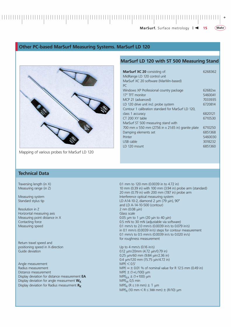
Mapping of various probes for MarSurf LD 120
Traversing length (in X) 0.1 mm to 120 mm (0.0039 in to 4.72 in)Measuring range (in Z) 10 mm (0.39 in) with 100 mm (3.94 in) probe arm (standard) 20 mm (0.79 in) with 200 mm (7.87 in) probe armMeasuring system Interference optical measuring systemStandard stylus tip LD A14-10-2, diamond 2 μm (79 μin), 90° and LD A-14-10-500 (contour)Resolution in Z 2 nm (0.08 μin)Horizontal measuring axis Glass scaleMeasuring point distance in X 0.05 μm to 1 μm (20 μin to 40 μin)Contacting force 0.5 mN to 30 mN (adjustable via software)Measuring speed 0.1 mm/s to 2.0 mm/s (0.0039 in/s to 0.079 in/s) in 0.1 mm/s (0.0039 in/s) steps for contour measurement 0.1 mm/s to 0.5 mm/s (0.0039 in/s to 0.020 in/s) for roughness measurementReturn travel speed andpositioning speed in X-direction Up to 4 mm/s (0.16 in/s)Guide deviation 0.12 μm/20mm (4.72 μin/0.79 in) 0.25 μm/60 mm (9.84 μin/2.36 in) 0.4 μm/120 mm (15.75 μin/4.72 in)Angle measurement MPE < 0.5‘Radius measurement MPE = ± 0.01 % of nominal value for R 12.5 mm (0.49 in)Distance measurement MPE ± (1+L/100) μmDisplay deviation for distance measurement EA MPEEA ± (1+100) μmDisplay deviation for angle measurment WK MPEW 0,5 minDisplay deviation for Radius measurment RK MPER (R ≤ 10 mm) ± 1 μm MPER (10 mm < R ≤ 300 mm) ± (R/10) μm
Technical Data
MarSurf XC 20 consisting of: 6268362MidRange LD 120 control unitMarSurf XC 20 software (MarWin-based)PCWindows XP Professional country package 62682xx17“ TFT monitor 5460041MCP 21 (advanced) 7033935LD 120 drive unit incl. probe system 6720814Contour 1 calibration standard for MarSurf LD 120,class 1 accuracy 6820121CT 200 XY table 6710530MarSurf ST 500 measuring stand with700 mm x 550 mm (27.56 in x 21.65 in) granite plate 6710250Damping elements set 6851368Printer 5460030USB cable 3018232LD 120 mount 6851360
Other PC-based MarSurf Measuring Systems. MarSurf LD 120
MarSurf LD 120 with ST 500 Measuring Stand
-
16 MarSurf. Sur face metro logy
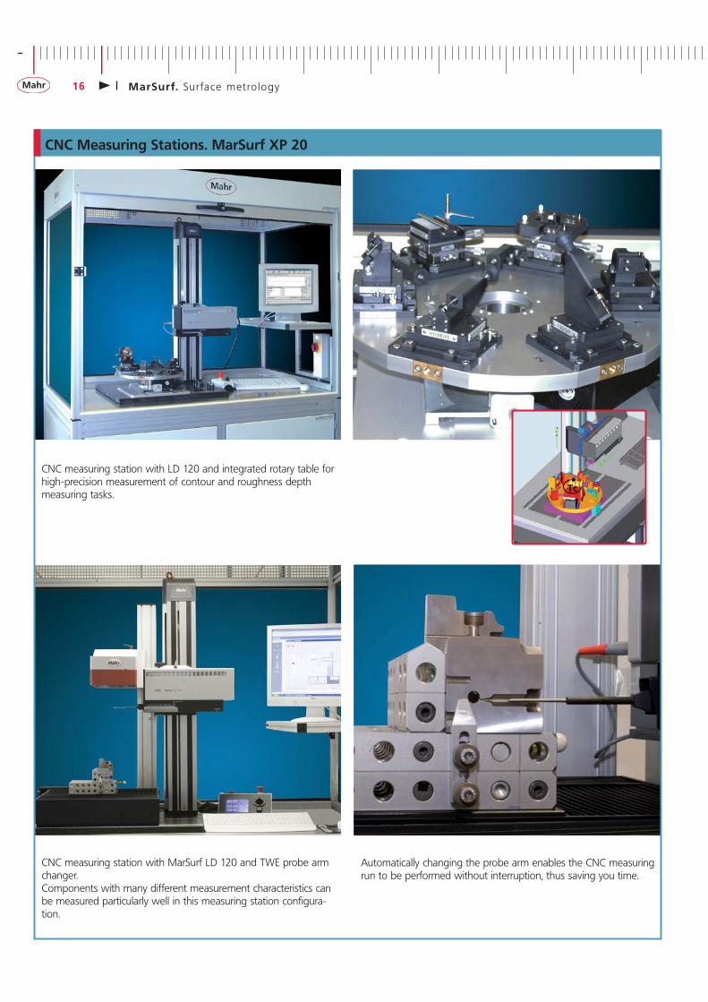
CNC measuring station with LD 120 and integrated rotary table for high-precision measurement of contour and roughness depth measuring tasks.
CNC measuring station with MarSurf LD 120 and TWE probe arm changer. Components with many different measurement characteristics can be measured particularly well in this measuring station configura-tion.
CNC Measuring Stations. MarSurf XP 20
Automatically changing the probe arm enables the CNC measuring run to be performed without interruption, thus saving you time.
+
MarSurf. Sur face metro logy 17
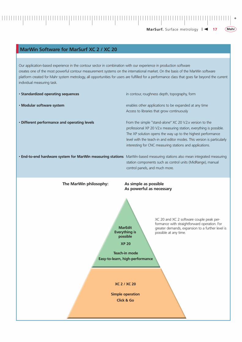
Our application-based experience in the contour sector in combination with our experience in production software
creates one of the most powerful contour measurement systems on the international market. On the basis of the MarWin software
platform created for Mahr system metrology, all opportunities for users are fulfilled for a performance class that goes far beyond the current
individual measuring task.
• Standardized operating sequences in contour, roughness depth, topography, form
• Modular software system enables other applications to be expanded at any time
Access to libraries that grow continuously
• Different performance and operating levels From the simple "stand-alone“ XC 20 V.2.x version to the
professional XP 20 V2.x measuring station, everything is possible.
The XP solution opens the way up to the highest performance
level with the teach-in and editor modes. This version is particularly
interesting for CNC measuring stations and applications.
• End-to-end hardware system for MarWin measuring stations MarWin-based measuring stations also mean integrated measuring
station components such as control units (MidRange), manual
control panels, and much more.
MarWin Software for MarSurf XC 2 / XC 20
MarEditEverything is
possible
XP 20
Teach-in mode
Easy-to-learn, high-performance
XC 2 / XC 20
Simple operation
Click & Go
XC 20 and XC 2 software couple peak per-formance with straightforward operation. For greater demands, expansion to a further level is possible at any time.
The MarWin philosophy: As simple as possible As powerful as necessary
-
18 MarSurf. Sur face metro logy
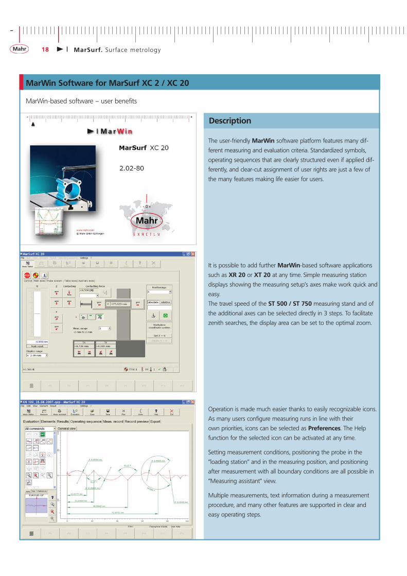
MarWin-based software – user benefits
Description
The user-friendly MarWin software platform features many dif-
ferent measuring and evaluation criteria. Standardized symbols,
operating sequences that are clearly structured even if applied dif-
ferently, and clear-cut assignment of user rights are just a few of
the many features making life easier for users.
It is possible to add further MarWin-based software applications
such as XR 20 or XT 20 at any time. Simple measuring station
displays showing the measuring setup’s axes make work quick and
easy.
The travel speed of the ST 500 / ST 750 measuring stand and of
the additional axes can be selected directly in 3 steps. To facilitate
zenith searches, the display area can be set to the optimal zoom.
Operation is made much easier thanks to easily recognizable icons.
As many users configure measuring runs in line with their
own priorities, icons can be selected as Preferences. The Help
function for the selected icon can be activated at any time.
Setting measurement conditions, positioning the probe in the
“loading station” and in the measuring position, and positioning
after measurement with all boundary conditions are all possible in
“Measuring assistant” view.
Multiple measurements, text information during a measurement
procedure, and many other features are supported in clear and
easy operating steps.
MarWin Software for MarSurf XC 2 / XC 20
+
MarSurf. Sur face metro logy 19
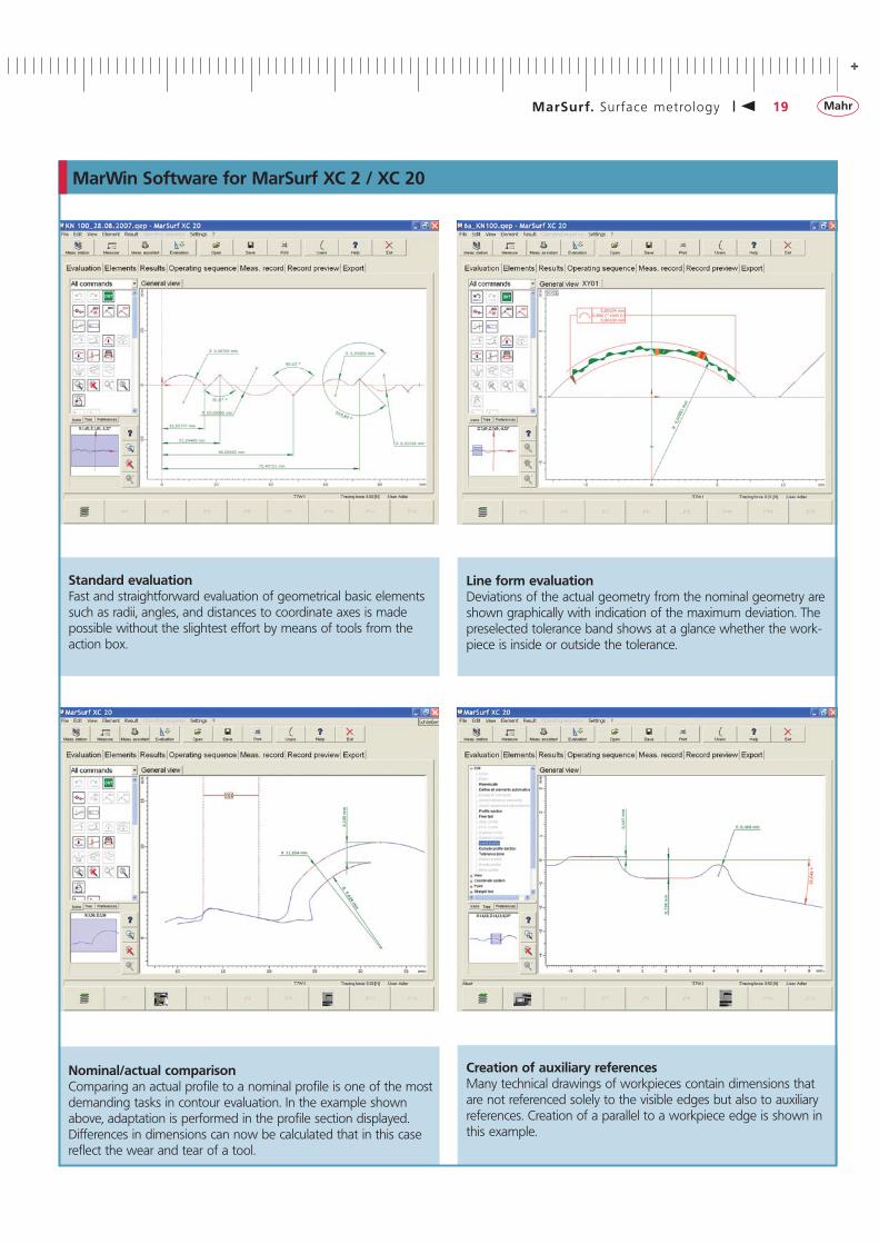
Line form evaluationDeviations of the actual geometry from the nominal geometry are shown graphically with indication of the maximum deviation. The preselected tolerance band shows at a glance whether the work-piece is inside or outside the tolerance.
Standard evaluationFast and straightforward evaluation of geometrical basic elements such as radii, angles, and distances to coordinate axes is made possible without the slightest effort by means of tools from the action box.
Nominal/actual comparisonComparing an actual profile to a nominal profile is one of the most demanding tasks in contour evaluation. In the example shown above, adaptation is performed in the profile section displayed. Differences in dimensions can now be calculated that in this case reflect the wear and tear of a tool.
MarWin Software for MarSurf XC 2 / XC 20
Creation of auxiliary referencesMany technical drawings of workpieces contain dimensions that are not referenced solely to the visible edges but also to auxiliary references. Creation of a parallel to a workpiece edge is shown in this example.
-
20 MarSurf. Sur face metro logy
MarWin Software for MarSurf XC 2 / XC 20
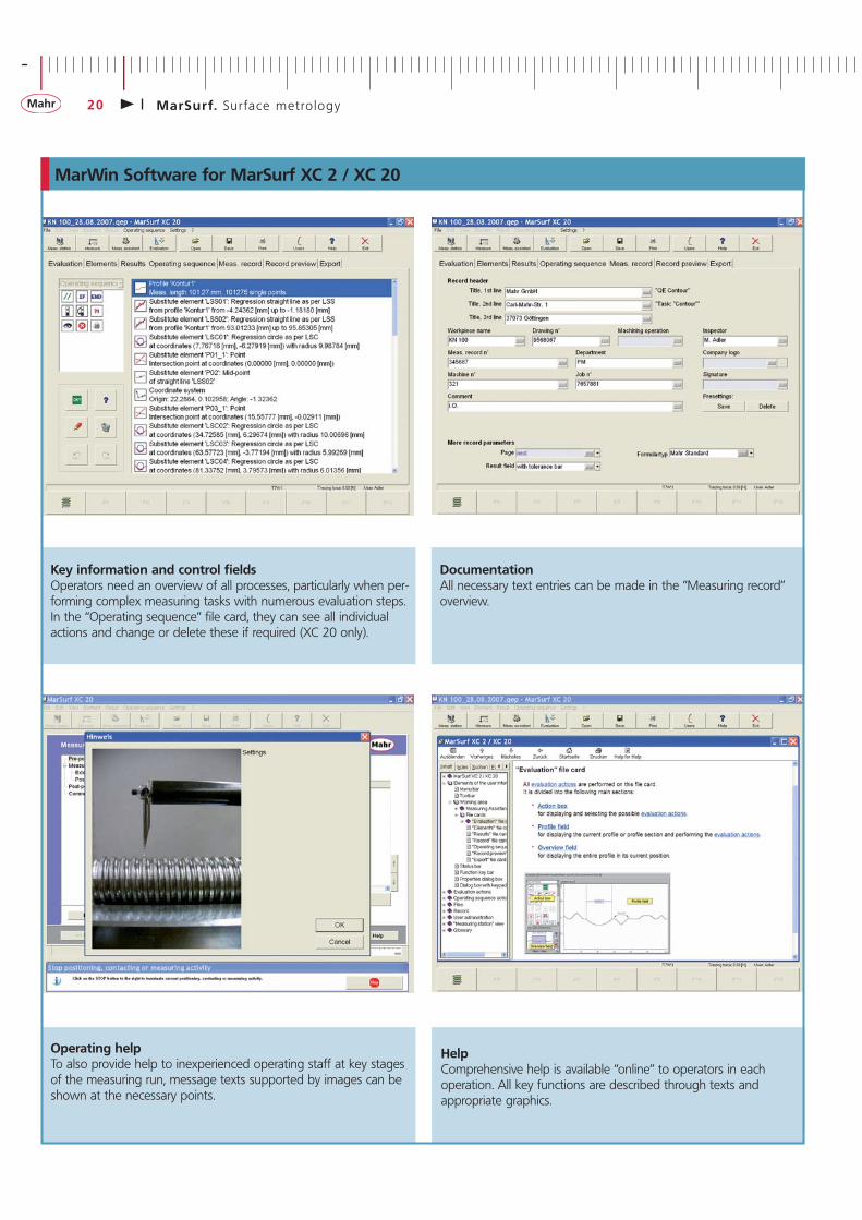
Key information and control fieldsOperators need an overview of all processes, particularly when per-forming complex measuring tasks with numerous evaluation steps. In the “Operating sequence” file card, they can see all individual actions and change or delete these if required (XC 20 only).
Operating helpTo also provide help to inexperienced operating staff at key stages of the measuring run, message texts supported by images can be shown at the necessary points.
HelpComprehensive help is available “online” to operators in each operation. All key functions are described through texts and appropriate graphics.
DocumentationAll necessary text entries can be made in the “Measuring record” overview.
+
MarSurf. Sur face metro logy 21
A key benefit of CD 120 / PCV 200 / LD 120 probe arms is that they can be changed without the need for tools, thanks to the use of the magnetic mount. The appropriate probe arms are therefore changed quickly and easily for different measuring tasks.
The calibration menu enables each probe arm to be calibrated and calibration data to be saved. Calibration is only necessary once for each probe arm. No further calibration is required when changing probe arms.
The KN 100 contour standard is used for practical monitoring of the measuring station. The standard contains the key geometrical elements. The KN 100 is supplied with a DKD or Mahr certificate if required.
KN 100 DKD calibration Order no. 6980110KN 100 Mahr calibration Order no. 9964316
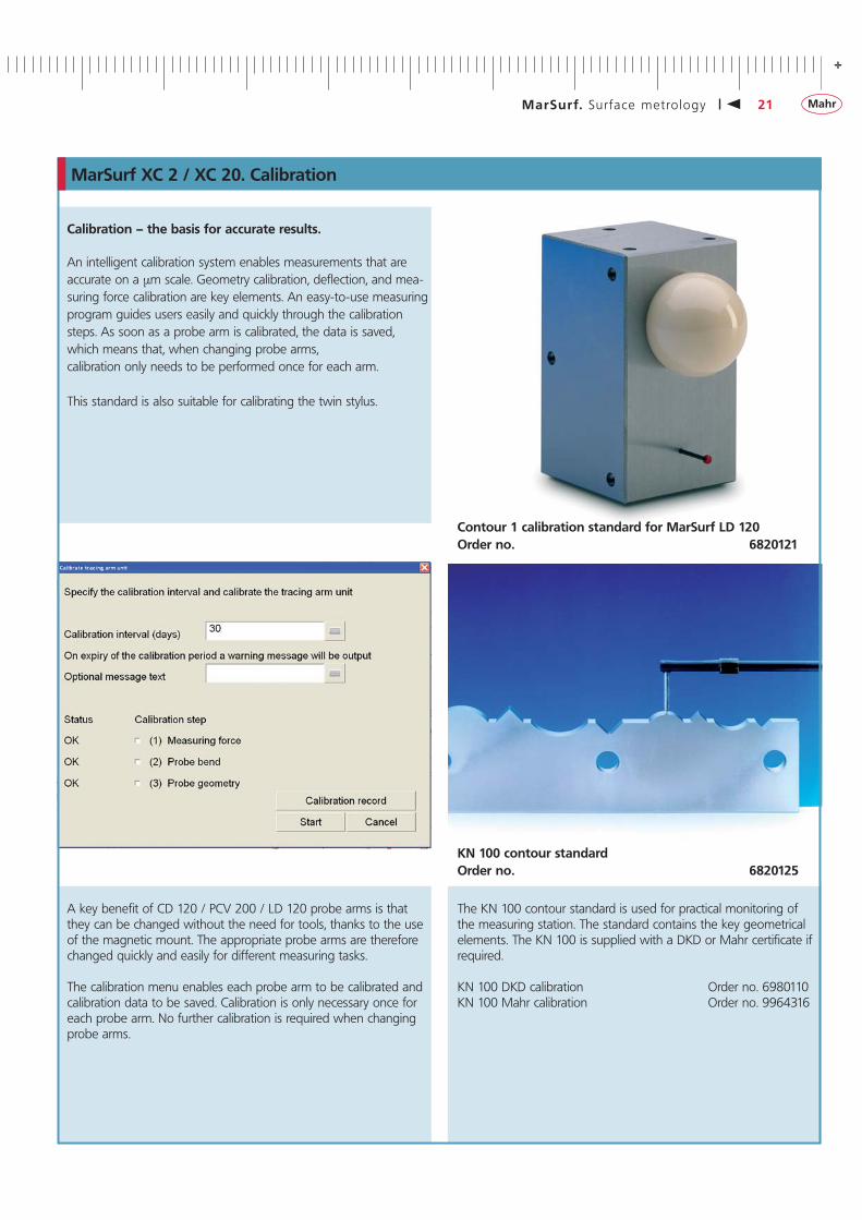
Calibration – the basis for accurate results.
An intelligent calibration system enables measurements that are accurate on a μm scale. Geometry calibration, deflection, and mea-suring force calibration are key elements. An easy-to-use measuring program guides users easily and quickly through the calibration steps. As soon as a probe arm is calibrated, the data is saved, which means that, when changing probe arms, calibration only needs to be performed once for each arm.
This standard is also suitable for calibrating the twin stylus.
MarSurf XC 2 / XC 20. Calibration
KN 100 contour standard Order no. 6820125
Contour 1 calibration standard for MarSurf LD 120 Order no. 6820121
-
22 MarSurf. Sur face metro logy
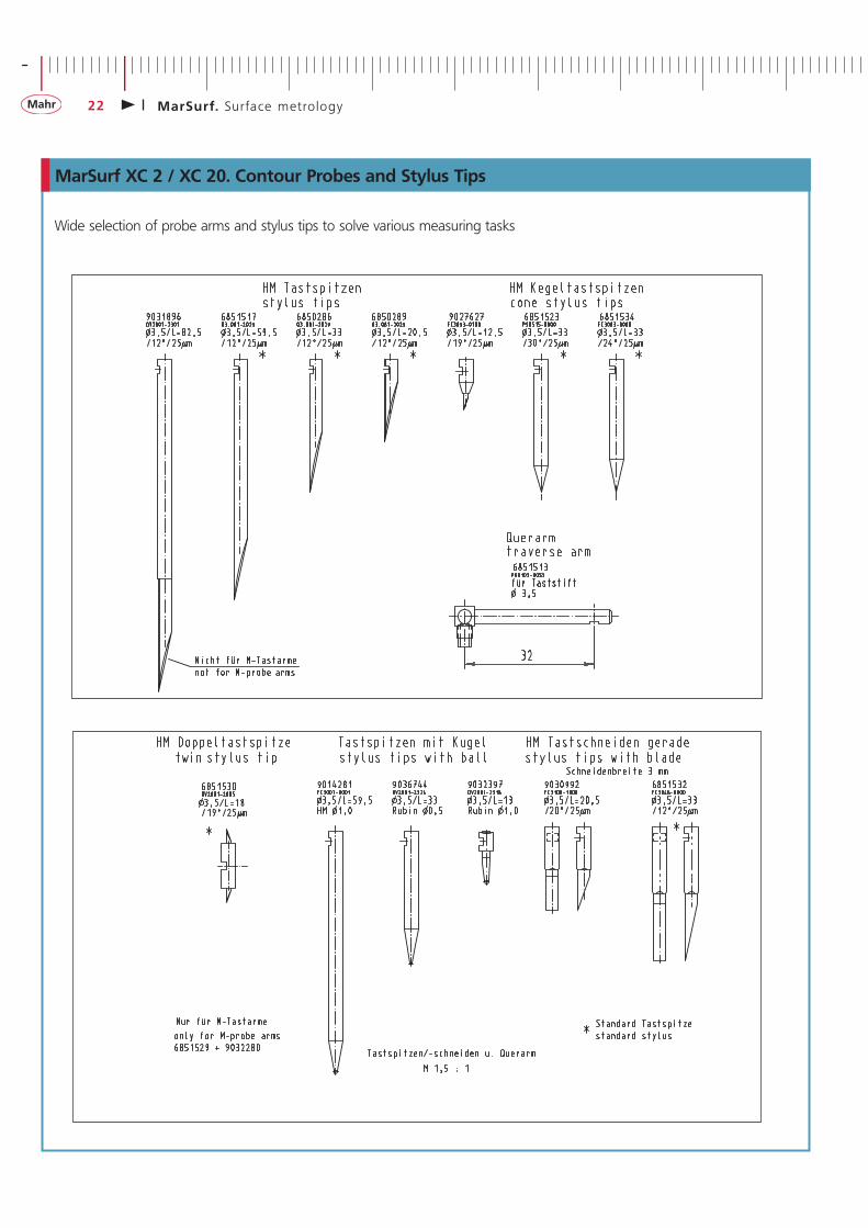
Wide selection of probe arms and stylus tips to solve various measuring tasks
MarSurf XC 2 / XC 20. Contour Probes and Stylus Tips
+
MarSurf. Sur face metro logy 23
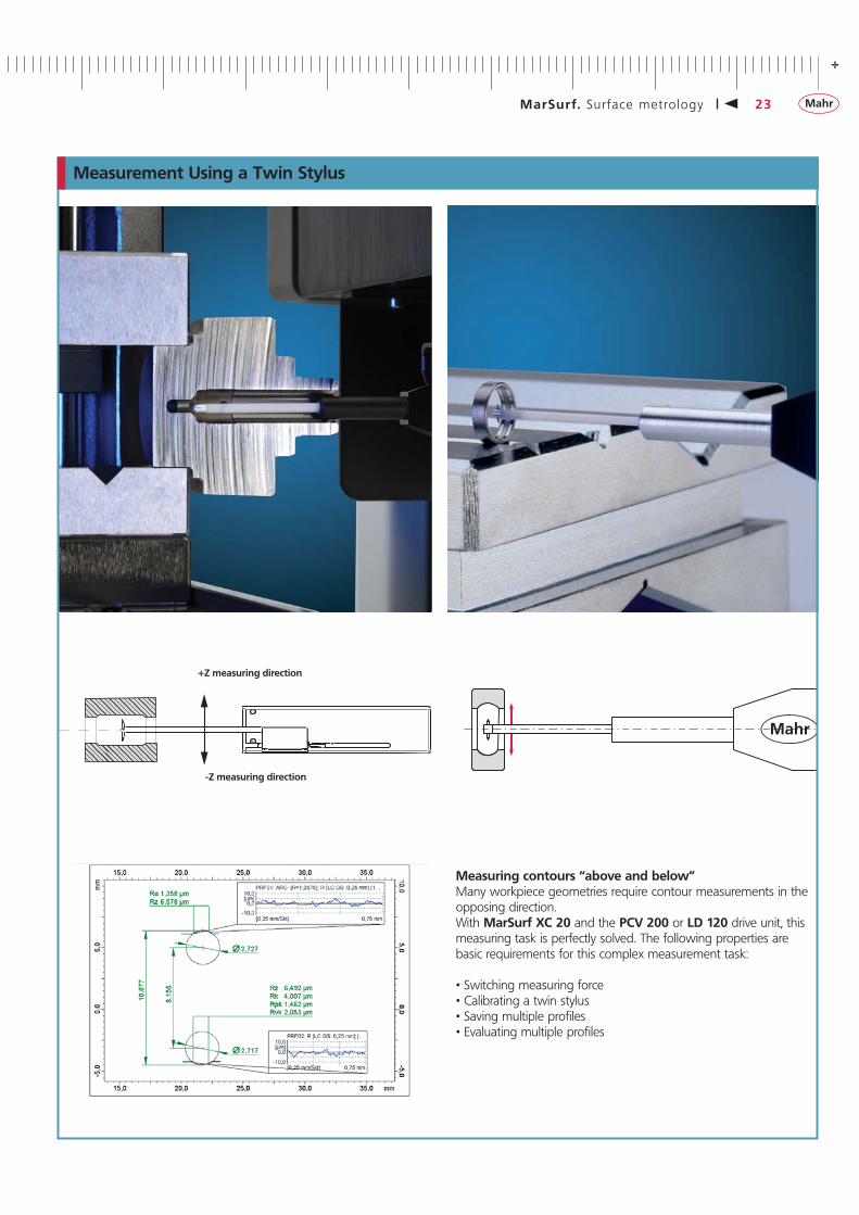
Measurement Using a Twin Stylus
+Z measuring direction
-Z measuring direction
Measuring contours “above and below”Many workpiece geometries require contour measurements in the opposing direction. With MarSurf XC 20 and the PCV 200 or LD 120 drive unit, this measuring task is perfectly solved. The following properties are basic requirements for this complex measurement task:
• Switching measuring force• Calibrating a twin stylus• Saving multiple profiles• Evaluating multiple profiles
-
24 MarSurf. Sur face metro logy
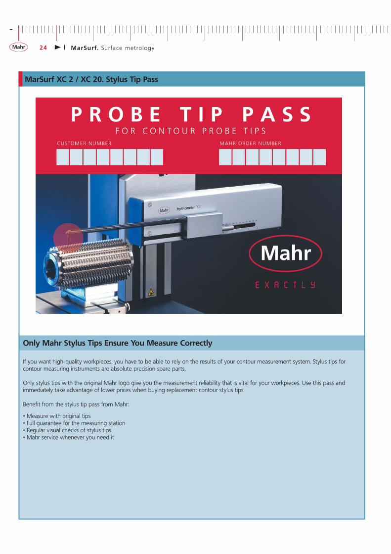
MarSurf XC 2 / XC 20. Stylus Tip Pass
Only Mahr Stylus Tips Ensure You Measure Correctly
If you want high-quality workpieces, you have to be able to rely on the results of your contour measurement system. Stylus tips for contour measuring instruments are absolute precision spare parts.
Only stylus tips with the original Mahr logo give you the measurement reliability that is vital for your workpieces. Use this pass and immediately take advantage of lower prices when buying replacement contour stylus tips.
Benefit from the stylus tip pass from Mahr:
• Measure with original tips• Full guarantee for the measuring station• Regular visual checks of stylus tips• Mahr service whenever you need it
+
MarSurf. Sur face metro logy 25
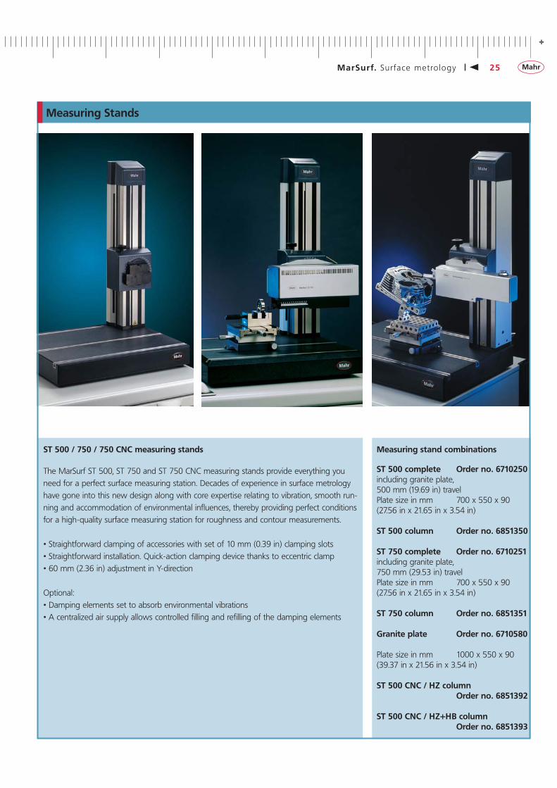
Measuring Stands
ST 500 / 750 / 750 CNC measuring stands
The MarSurf ST 500, ST 750 and ST 750 CNC measuring stands provide everything you need for a perfect surface measuring station. Decades of experience in surface metrology have gone into this new design along with core expertise relating to vibration, smooth run-ning and accommodation of environmental influences, thereby providing perfect conditions for a high-quality surface measuring station for roughness and contour measurements.
• Straightforward clamping of accessories with set of 10 mm (0.39 in) clamping slots• Straightforward installation. Quick-action clamping device thanks to eccentric clamp• 60 mm (2.36 in) adjustment in Y-direction
Optional:• Damping elements set to absorb environmental vibrations• A centralized air supply allows controlled filling and refilling of the damping elements
Measuring stand combinations
ST 500 complete Order no. 6710250including granite plate,500 mm (19.69 in) travelPlate size in mm 700 x 550 x 90 (27.56 in x 21.65 in x 3.54 in)
ST 500 column Order no. 6851350
ST 750 complete Order no. 6710251including granite plate,750 mm (29.53 in) travelPlate size in mm 700 x 550 x 90 (27.56 in x 21.65 in x 3.54 in)
ST 750 column Order no. 6851351
Granite plate Order no. 6710580
Plate size in mm 1000 x 550 x 90 (39.37 in x 21.56 in x 3.54 in)
ST 500 CNC / HZ column Order no. 6851392
ST 500 CNC / HZ+HB column Order no. 6851393
-
26 MarSurf. Sur face metro logy
Manual Control Panels
MCP 23 Order no. 7035195with emergency stop function and release button
MCP 21 Order no. 7039135With emergency stop function, release button, touchscreen and joystick
MarSurf. Damping Set (not illustrated)
Measuring Stand Accessories
Damping set for workpieces of 0 kg to 100 kg (0 lbs to 220 lbs). MarSurf damping set 1 consists of:• 4 pneumatic-spring elements• Supply line kit• Air pump (with pressure gage)Load capacity: 20 kg to 60 kg (44 lbs to 132 lbs) x 4 units = 80 kg to 240 kg (176 lbs to 528 lbs) Weight of granite plate + column: 80 kg + 50 kg = 130 kg (176 lbs + 110 lbs = 286 lbs)Max. permissible workpiece weight: approx. 100 kg (220 lbs)
Order no. 6851368
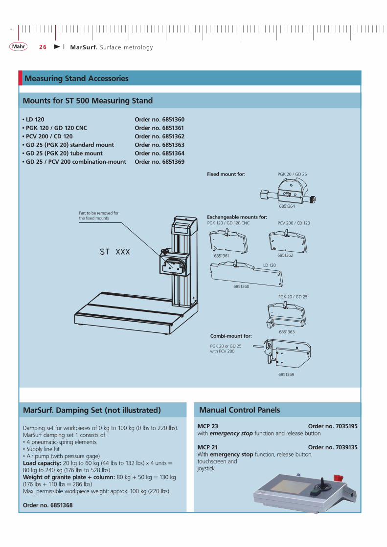
Mounts for ST 500 Measuring Stand
• LD 120 Order no. 6851360• PGK 120 / GD 120 CNC Order no. 6851361• PCV 200 / CD 120 Order no. 6851362• GD 25 (PGK 20) standard mount Order no. 6851363• GD 25 (PGK 20) tube mount Order no. 6851364• GD 25 / PCV 200 combination-mount Order no. 6851369
PGK 120 / GD 120 CNC PCV 200 / CD 120
PGK 20 / GD 25
6851361 6851362
6851363
PGK 20 / GD 25
6851364
LD 120
6851360
Fixed mount for:
Exchangeable mounts for:
Combi-mount for:
6851369
PGK 20 or GD 25with PCV 200
Part to be removed forthe fixed mounts
+
MarSurf. Sur face metro logy 27
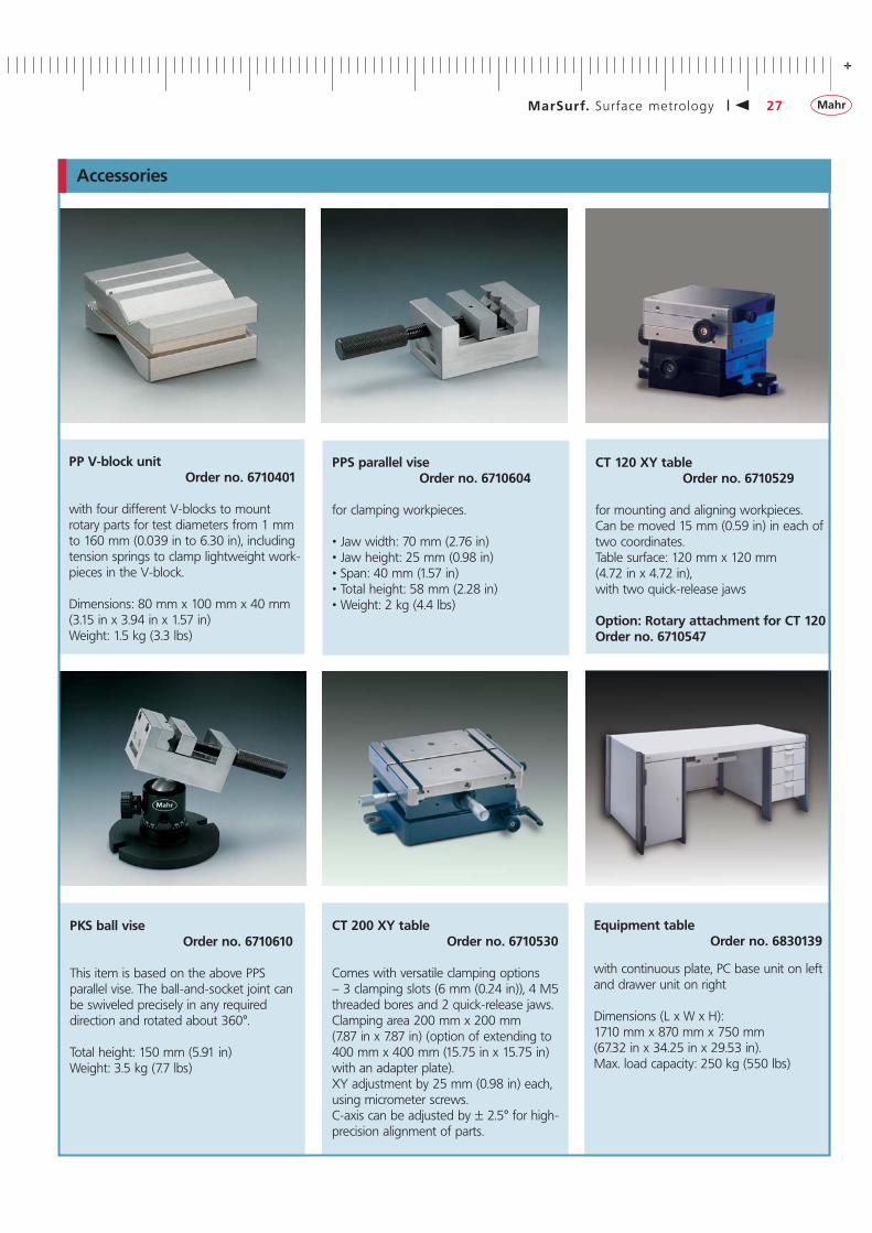
CT 200 XY table Order no. 6710530
Comes with versatile clamping options – 3 clamping slots (6 mm (0.24 in)), 4 M5 threaded bores and 2 quick-release jaws. Clamping area 200 mm x 200 mm (7.87 in x 7.87 in) (option of extending to 400 mm x 400 mm (15.75 in x 15.75 in) with an adapter plate). XY adjustment by 25 mm (0.98 in) each, using micrometer screws. C-axis can be adjusted by ± 2.5° for high-precision alignment of parts.
CT 120 XY table Order no. 6710529
for mounting and aligning workpieces. Can be moved 15 mm (0.59 in) in each of two coordinates.Table surface: 120 mm x 120 mm (4.72 in x 4.72 in),with two quick-release jaws
Option: Rotary attachment for CT 120Order no. 6710547
PPS parallel vise Order no. 6710604
for clamping workpieces.
• Jaw width: 70 mm (2.76 in)• Jaw height: 25 mm (0.98 in)• Span: 40 mm (1.57 in)• Total height: 58 mm (2.28 in)• Weight: 2 kg (4.4 lbs)
PKS ball vise Order no. 6710610
This item is based on the above PPS parallel vise. The ball-and-socket joint canbe swiveled precisely in any required direction and rotated about 360°.
Total height: 150 mm (5.91 in)Weight: 3.5 kg (7.7 lbs)
PP V-block unit Order no. 6710401
with four different V-blocks to mount rotary parts for test diameters from 1 mm to 160 mm (0.039 in to 6.30 in), including tension springs to clamp lightweight work-pieces in the V-block.
Dimensions: 80 mm x 100 mm x 40 mm (3.15 in x 3.94 in x 1.57 in)Weight: 1.5 kg (3.3 lbs)
Equipment table Order no. 6830139
with continuous plate, PC base unit on left and drawer unit on right
Dimensions (L x W x H):1710 mm x 870 mm x 750 mm(67.32 in x 34.25 in x 29.53 in).Max. load capacity: 250 kg (550 lbs)
Accessories
- +
3759
691-
07.0
4.20
08
© by Mahr GmbH, GöttingenWe reserve the right to make changes to our products, especially dueto technical improvements and further developments.All illustrations and technical data are therefore without guarantee.
Mahr GmbH Göttingen
Postfach 1853, D-37008 Göttingen; Carl-Mahr-Str. 1, D-37073 Göttingen; Phone: +49 (551) 707 30, Fax +49 (551) 710 21; eMail: [email protected]
WWW.MAHR.COM


