36
MARTIN ® Inspection Door Operator’s Manual M3127 Go to MARTIN ® Inspection Door web page

MARTIN® Inspection Door
Operator’s Manual M3127
Go to MARTIN® Inspection Door web page
ImportantMARTIN ENGINEERING HEREBY DISCLAIMS ANY LIABILITY FOR: DAMAGE DUE TO CONTAMINATION OF THE MATERIAL; USER’S FAILURE TO INSPECT, MAINTAIN AND TAKE REASONABLE CARE OF THE EQUIPMENT; INJURIES OR DAMAGE RESULTING FROM USE OR APPLICATION OF THIS PRODUCT CONTRARY TO INSTRUCTIONS AND SPECIFICATIONS CONTAINED HEREIN. MARTIN ENGINEERING’S LIABILITY SHALL BE LIMITED TO REPAIR OR REPLACEMENT OF EQUIPMENT SHOWN TO BE DEFECTIVE.Observe all safety rules given herein along with owner and Government standards and regulations. Know and understand lockout/tagout procedures as defined by American National Standards Institute (ANSI) z244.1-1982, American National Standard for Personnel Protection - Lockout/Tagout of Energy Sources - Minimum Safety Requirements and Occupational Safety and Health Administration (OSHA) Federal Register, Part IV, 29 CFR Part 1910, Control of Hazardous Energy Source (Lockout/Tagout); Final Rule.
The following symbols may be used in this manual:
DANGER!
Danger: Immediate hazards that will result in severe personal injury or death.
WARNING!
Warning: Hazards or unsafe practices that could result in personal injury.
CAUTION!
Caution: Hazards or unsafe practices that could result in product or property damages.
IMPORTANTImportant: Instructions that must be followed to ensure proper installation/operation of equipment.
NOTENote: General statements to assist the reader.

Martin Engineering M3127-10/10 i MARTIN® Inspection Door
Table of Contents
Section PageList of Figures and Tables . . . . . . . . . . . . . . . . . . . . . . . . . . . . . . . . . . . . . . . . . . . . . . . . . . . ii
Introduction . . . . . . . . . . . . . . . . . . . . . . . . . . . . . . . . . . . . . . . . . . . . . . . . . . . . . . . . . . . . . . 1General . . . . . . . . . . . . . . . . . . . . . . . . . . . . . . . . . . . . . . . . . . . . . . . . . . . . . . . . . . . . . . . . . . . . . . 1
MARTIN® Inspection Door materials . . . . . . . . . . . . . . . . . . . . . . . . . . . . . . . . . . . . . . . . . . . . . . 1
References . . . . . . . . . . . . . . . . . . . . . . . . . . . . . . . . . . . . . . . . . . . . . . . . . . . . . . . . . . . . . . . . . . . 1
Safety . . . . . . . . . . . . . . . . . . . . . . . . . . . . . . . . . . . . . . . . . . . . . . . . . . . . . . . . . . . . . . . . . . . . . . . 1
Materials required . . . . . . . . . . . . . . . . . . . . . . . . . . . . . . . . . . . . . . . . . . . . . . . . . . . . . . . . . . . . . 1
Before Installing MARTIN® Inspection Door. . . . . . . . . . . . . . . . . . . . . . . . . . . . . . . . . . . . 2
Installing MARTIN® Inspection Door. . . . . . . . . . . . . . . . . . . . . . . . . . . . . . . . . . . . . . . . . . 3MARTIN® Rubber Inspection Door . . . . . . . . . . . . . . . . . . . . . . . . . . . . . . . . . . . . . . . . . . . . . . . 3
MARTIN® Steel Inspection Door . . . . . . . . . . . . . . . . . . . . . . . . . . . . . . . . . . . . . . . . . . . . . . . . . 4
MARTIN® Inspection Door with Screen. . . . . . . . . . . . . . . . . . . . . . . . . . . . . . . . . . . . . . . . . . . . 6
After Installing MARTIN® Inspection Door . . . . . . . . . . . . . . . . . . . . . . . . . . . . . . . . . . . . . 9
Weekly Maintenance . . . . . . . . . . . . . . . . . . . . . . . . . . . . . . . . . . . . . . . . . . . . . . . . . . . . . . . 9
Part Numbers . . . . . . . . . . . . . . . . . . . . . . . . . . . . . . . . . . . . . . . . . . . . . . . . . . . . . . . . . . . . . 10
Appendix A. MARTIN® Inspection Door Labels . . . . . . . . . . . . . . . . . . . . . . . . . . . . . . . . . A-1
Appendix B. MARTIN® Inspection Door Dimensions . . . . . . . . . . . . . . . . . . . . . . . . . . . . . B-1
Tab
le o
f C
onte
nts
Martin Engineering M3127-10/10 ii MARTIN® Inspection Door
List of Figures
Figure Title Page1 Installing MARTIN® Inspection Door . . . . . . . . . . . . . . . . . . . . . . . . . . . . . . . 3
2 Installing MARTIN® Steel Inspection Door . . . . . . . . . . . . . . . . . . . . . . . . . . 5
3 Installing MARTIN® Inspection Door With Screen. . . . . . . . . . . . . . . . . . . . . 6
4 Installing MARTIN® Inspection Door With Screen (Side Detail) . . . . . . . . . . 7
5 Cutting Screen for “L” Bracket Installation . . . . . . . . . . . . . . . . . . . . . . . . . . . 7
6 MARTIN® Rubber Inspection Door Assemblies, P/N CYAR-XXXXXXXX . . . . . . . . . . . . . . . . . . . . . . . . . . . . . . . . . . . . . . . . 12
7 MARTIN® Steel Inspection Door, P/N CYA-XXXXXXXXXX . . . . . . . . . . . 14
8 MARTIN® Steel Inspection Door, P/N CYA-XXXXXXXXXX . . . . . . . . . . . 16
9 MARTIN® Extended-Height Steel Inspection Door, P/N CYAE-XXXX-XXXXXX . . . . . . . . . . . . . . . . . . . . . . . . . . . . . . . . . . . . . 19
10 MARTIN® Round Steel Inspection Door Assembly,P/N CYARD-XXXX. . . . . . . . . . . . . . . . . . . . . . . . . . . . . . . . . . . . . . . . . . . . . 21
List of Tables
Table Title PageI MARTIN® Inspection Door Specifications . . . . . . . . . . . . . . . . . . . . . . . . . . 1
II MARTIN® Rubber Inspection Door Part Numbers and Quantities . . . . . . . . 13
III MARTIN® Steel Inspection Door Part Numbers and Quantities . . . . . . . . . . 15
IV MARTIN® Steel Inspection Door Part Numbers and Quantities . . . . . . . . . . 18
V MARTIN® Extended-Height Steel Inspection Door Part Numbers and Quantities . . . . . . . . . . . . . . . . . . . . . . . . . . . . . . . . . . . . . . . . . . . . . . . . . . . . 20
VI MARTIN® Round Steel Inspection Door AssemblyPart Numbers and Quantities . . . . . . . . . . . . . . . . . . . . . . . . . . . . . . . . . . . . . 22
Lis
t of
Fig
ures
/Tab
les

Martin Engineering M3127-10/10 1 MARTIN® Inspection Door
Introduction
General MARTIN® Inspection Doors are used to access mechanical equipment for service or to clean out material buildup. They can also be used as electrical switchboard covers, splash covers, and visual inspection doors. MARTIN® Inspection Doors were not designed to be mounted horizontally in areas where they may be stepped on.
Appendix A shows MARTIN® Inspection Door labels and Appendix B shows MARTIN® Inspection Door dimensions.
MARTIN® Inspection Door materials
MARTIN® Inspection Doors are made of a variety of materials to meet most needs. The nitrile and silicone doors are oil resistant and can be used in higher-temperature applications (see Table I). The silicone door is approved by the Food and Drug Administration (FDA) for use in the food industry (see Table I).
If you have questions about a particular MARTIN® Inspection Door’s compatibility with certain chemicals, consult the Elastomer Chemical Compatibility Chart for MARTIN® Conveyor Products, available from Martin Engineering or representative. Table I shows the specifications for MARTIN® Inspection Doors.
Table I. MARTIN® Inspection Door Specifications
References The following documents are referenced in this manual:
• American National Standards Institute (ANSI) z244.1-1982, American National Standard for Personnel Protection - Lockout/Tagout of Energy Sources - Minimum Safety Requirements, American National Standards Institute, Inc., 1430 Broadway, New York, NY 10018.
• Federal Register, Volume 54, Number 169, Part IV, 29 CFR Part 1910, Control of Hazardous Energy Source (Lockout/Tagout); Final Rule, Department of Labor, Occupational Safety and Health Administration (OSHA), 32nd Floor, Room 3244, 230 South Dearborn Street, Chicago, IL 60604.
• Elastomer Chemical Compatibility Chart for MARTIN® Conveyor Products, Martin Engineering.
Safety All safety rules defined in the above documents and all owner/employer safety rules must be strictly followed when installing and servicing this equipment.
Materials required Only standard hand tools are required to install and service this equipment.
Type of MARTIN® Inspection Door
Max. Operating Temperature
Max. Pressurepsi (bar)
Max. Vacuumpsi (bar)
Rubber 155°F (68°C) .29 (.020) .36 (.025)
Nitrile 250°F (121°C) .29 (.020) .36 (.025)
Silicone 400°F (204°C) .29 (.020) .36 (.025)
Screen 155°F (68°C) — —
Steel 350°F (177°C) — —
Intr
oduc
tion

Martin Engineering M3127-10/10 2 MARTIN® Inspection Door
Before Installing MARTIN® Inspection Door
IMPORTANTThe delivery service is responsible for damage occurring in transit. Martin Engineering CANNOT enter claims for damages. Contact your transportation agent for more information.
1. Inspect shipping container for damage. Report damage to delivery service immediately and fill out delivery service’s claim form. Keep any damaged goods subject to examination.
2. Remove MARTIN® Inspection Door from shipping container. Equipment in container should include the following:
• MARTIN® Inspection Door.
• MARTIN® Inspection Door Warning Label, P/N 30382.
3. If anything is missing, contact Martin Engineering or representative.
WARNING!
Before installing or servicing equipment, turn off and lock out/tag out energy source to conveyor and conveyor accessories.
4. Turn off and lock out/tag out energy source according to ANSI standards (see “References”).
WARNING!
If equipment will be installed in an enclosed area, test gas level or dust content before using a cutting torch or welding. Using a cutting torch or welding in an area with gas or dust may cause an explosion.
5. If using a cutting torch or welding, test atmosphere for gas level or dust content. Cover conveyor belt with fire retardant cover.
Bef
ore
Inst
alla
tion

Martin Engineering M3127-10/10 3 MARTIN® Inspection Door
Installing MARTIN® Inspection Door
IMPORTANTRead entire section before beginning work.
WARNING!
Do not mount MARTIN® Inspection Door as follows: facing downward, in direct path of material, where door can be used as a step, or where material can collect in cover.
1. Determine location of MARTIN® Inspection Door on wall.
2. Follow the procedure under “MARTIN® Rubber Inspection Door,” “MARTIN® Steel Inspection Door” or “MARTIN® Inspection Door With Screen.”
MARTIN® Rubber Inspection Door
IMPORTANTMARTIN® Rubber Inspection Doors should only be used
when belt cleaner mainframe is required to extend through the door.
1. Remove rubber door (A, Figure 1) from door frame (B).
2. Using door frame as template, mark location of mounting holes and inside dimension of door (access opening) on wall.
NOTEMartin Engineering recommends bolting rather than welding MARTIN® Inspection Door frame to wall.
3. Using saw or cutting torch, cut hole for access opening 1/8 in. (3 mm) larger than access opening marked on wall. If you are bolting door frame to wall, drill holes for mounting screws. Remove burrs and sharp edges.
Figure 1. Installing MARTIN® Inspection Door
A
B
C
D
A.B.C.D.
Rubber doorDoor frameCableHex head cap screw (8)Flat washer (8)
Hex nut (8)Compression washer (8)
E
E. Stud (4 or 8)
Inst
alla
tion

Martin Engineering M3127-10/10 4 MARTIN® Inspection Door
4. Grind wall surface smooth where door frame will contact it.
5. Bolt or weld MARTIN® Inspection Door frame (B) and cable (C) to wall as follows.
a. If bolting, do the following:
(1) Place cable eyelet on one of eight hex head cap screws (D).
(2) Install eight hex head cap screws, flat washers, compression washers, and hex nuts in drilled mounting holes. Install screw holding cable in a corner hole.
(3) Caulk around door frame to seal it to wall.
b. If welding, do the following:
(1) Tack weld door frame to wall, then skip weld 1/2 in. (12.7 mm) every 2 in. (51 mm).
(2) Tack weld cable to wall or door frame.
(3) Caulk around door frame to seal it to wall.
6. Push holes in rubber door (A) over studs (E) on door frame (B) until door opening is sealed.
MARTIN® Steel Inspection Door
NOTEMartin Engineering recommends installing MARTIN® Steel Inspection Door with hinges to the side or bottom.
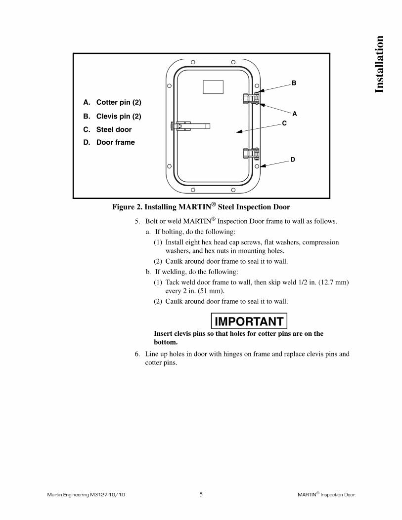
1. Remove two cotter pins (A, Figure 2) and two clevis pins (B) from door hinges. Remove steel door (C) from frame (D).
2. Using door frame as template, mark location of mounting holes and inside dimension of door (access opening) on wall.
NOTEMartin Engineering recommends bolting rather than welding MARTIN® Inspection Door frame to wall.
3. Using saw or cutting torch, cut hole for access opening 1/8 in. (3 mm) larger than access opening marked on wall. If you are bolting door frame to wall, drill holes for mounting screws. Remove burrs and sharp edges.
4. Grind wall surface smooth where door frame will contact it.
Inst
alla
tion
Martin Engineering M3127-10/10 5 MARTIN® Inspection Door
Figure 2. Installing MARTIN® Steel Inspection Door
5. Bolt or weld MARTIN® Inspection Door frame to wall as follows.
a. If bolting, do the following:
(1) Install eight hex head cap screws, flat washers, compression washers, and hex nuts in mounting holes.
(2) Caulk around door frame to seal it to wall.
b. If welding, do the following:
(1) Tack weld door frame to wall, then skip weld 1/2 in. (12.7 mm) every 2 in. (51 mm).
(2) Caulk around door frame to seal it to wall.
IMPORTANTInsert clevis pins so that holes for cotter pins are on the bottom.
6. Line up holes in door with hinges on frame and replace clevis pins and cotter pins.
A.
B.
C.
D.
Cotter pin (2)
Clevis pin (2)
Steel door
Door frame
AC
D
B
Inst
alla
tion
Martin Engineering M3127-10/10 6 MARTIN® Inspection Door
MARTIN® Inspection Door with Screen
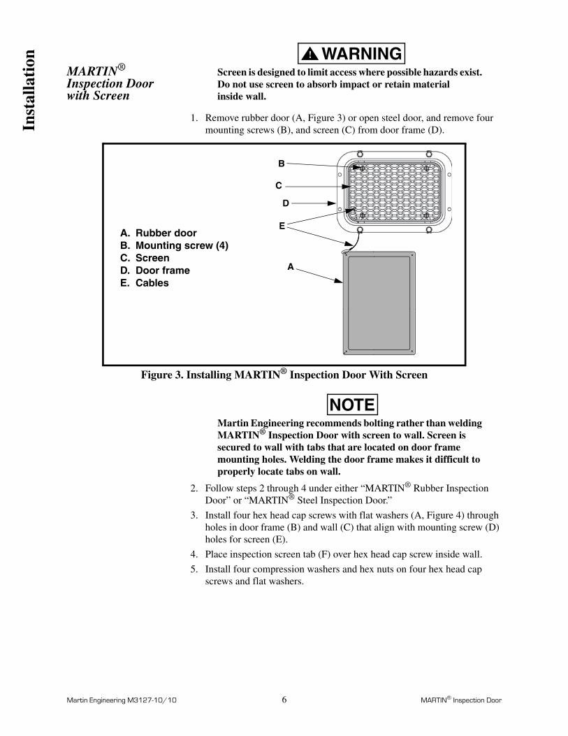
WARNING!
Screen is designed to limit access where possible hazards exist. Do not use screen to absorb impact or retain material inside wall.
1. Remove rubber door (A, Figure 3) or open steel door, and remove four mounting screws (B), and screen (C) from door frame (D).
Figure 3. Installing MARTIN® Inspection Door With Screen
NOTEMartin Engineering recommends bolting rather than welding MARTIN® Inspection Door with screen to wall. Screen is secured to wall with tabs that are located on door frame mounting holes. Welding the door frame makes it difficult to properly locate tabs on wall.
2. Follow steps 2 through 4 under either “MARTIN® Rubber Inspection Door” or “MARTIN® Steel Inspection Door.”
3. Install four hex head cap screws with flat washers (A, Figure 4) through holes in door frame (B) and wall (C) that align with mounting screw (D) holes for screen (E).
4. Place inspection screen tab (F) over hex head cap screw inside wall.
5. Install four compression washers and hex nuts on four hex head cap screws and flat washers.
A
B
A.B.C.D.
Rubber doorMounting screw (4)ScreenDoor frame
C
D
CablesE.
E
Inst
alla
tion

Martin Engineering M3127-10/10 7 MARTIN® Inspection Door
Figure 4. Installing MARTIN® Inspection Door With Screen (Side Detail)
6. If using “L” bracket or another assembly for mounting a belt cleaner, cut a 2-1/2-in. (63.5-mm) arch in screen as shown in Figure 5, and install mount assembly. (See applicable belt cleaner operator’s manual for mount installation instructions.)
Figure 5. Cutting Screen for “L” Bracket Installation
7. Install four mounting screws (D, Figure 4) through screen (E) and inspection screen tabs (F).
8. Place rubber door cable eyelet and screen cable eyelet (E, Figure 3) on one of four hex head cap screws not installed.
9. Install remaining four hex head cap screws, flat washers, compression washers, and hex nuts (A, Figure 4). Install screw holding cables in a corner hole.
10. Caulk around door frame to seal it to wall.
11. Push holes in rubber door (G) over studs (H) on door frame until door opening is sealed.
F
A
D
E
B
C
G
H
A.
B.C.D.E.F.G.H.
Hex head cap screw (8)Flat washer (8)Compression washer (8)Hex nut (8)Door frameWallMounting screw (4)ScreenInspection screen tabRubber doorStud
Inst
alla
tion

Notes

Martin Engineering M3127-10/10 9 MARTIN® Inspection Door
After Installing MARTIN® Inspection Door
1. Thoroughly wipe wall clean above MARTIN® Inspection Door. Place MARTIN® Inspection Door Warning Label, P/N 30382 on wall visible to anyone using MARTIN® Inspection Door.
2. Observe MARTIN® Inspection Door during normal operations. If material is escaping through door, make sure rubber door is securely seated against door frame or steel door is firmly seated against rubber silicone seal. Check caulk around door frame for leaks.
Weekly Maintenance
1. Make sure all fasteners are tight. Tighten if necessary.
2. Wipe all warning labels clean. If labels are damaged or are not readable, contact Martin Engineering or representative for replacements.
3. Check rubber door for tears, holes, or cracks. Replace as necessary.
4. Check silicone sponge seal around steel door for tears or cracks. Replace as necessary.
Aft
er I
nsta
llati
on/M
aint
enan
ce
Martin Engineering M3127-10/10 10 MARTIN® Inspection Door
Part Numbers
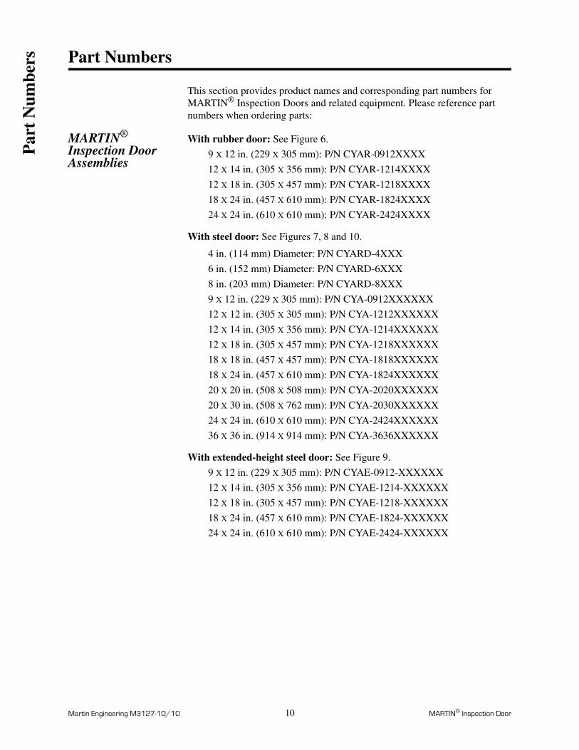
This section provides product names and corresponding part numbers for MARTIN® Inspection Doors and related equipment. Please reference part numbers when ordering parts:
MARTIN® Inspection Door Assemblies
With rubber door: See Figure 6.
9 X 12 in. (229 X 305 mm): P/N CYAR-0912XXXX
12 X 14 in. (305 X 356 mm): P/N CYAR-1214XXXX
12 X 18 in. (305 X 457 mm): P/N CYAR-1218XXXX
18 X 24 in. (457 X 610 mm): P/N CYAR-1824XXXX
24 X 24 in. (610 X 610 mm): P/N CYAR-2424XXXX
With steel door: See Figures 7, 8 and 10.
4 in. (114 mm) Diameter: P/N CYARD-4XXX
6 in. (152 mm) Diameter: P/N CYARD-6XXX
8 in. (203 mm) Diameter: P/N CYARD-8XXX
9 X 12 in. (229 X 305 mm): P/N CYA-0912XXXXXX
12 X 12 in. (305 X 305 mm): P/N CYA-1212XXXXXX
12 X 14 in. (305 X 356 mm): P/N CYA-1214XXXXXX
12 X 18 in. (305 X 457 mm): P/N CYA-1218XXXXXX
18 X 18 in. (457 X 457 mm): P/N CYA-1818XXXXXX
18 X 24 in. (457 X 610 mm): P/N CYA-1824XXXXXX
20 X 20 in. (508 X 508 mm): P/N CYA-2020XXXXXX
20 X 30 in. (508 X 762 mm): P/N CYA-2030XXXXXX
24 X 24 in. (610 X 610 mm): P/N CYA-2424XXXXXX
36 X 36 in. (914 X 914 mm): P/N CYA-3636XXXXXX
With extended-height steel door: See Figure 9.
9 X 12 in. (229 X 305 mm): P/N CYAE-0912-XXXXXX
12 X 14 in. (305 X 356 mm): P/N CYAE-1214-XXXXXX
12 X 18 in. (305 X 457 mm): P/N CYAE-1218-XXXXXX
18 X 24 in. (457 X 610 mm): P/N CYAE-1824-XXXXXX
24 X 24 in. (610 X 610 mm): P/N CYAE-2424-XXXXXX
Par
t N
umbe
rs
Martin Engineering M3127-10/10 11 MARTIN® Inspection Door
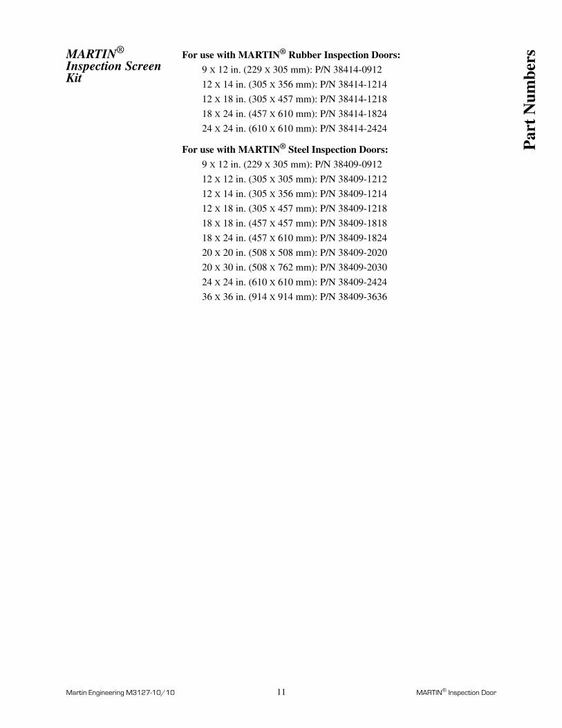
MARTIN® Inspection Screen Kit
For use with MARTIN® Rubber Inspection Doors:
9 X 12 in. (229 X 305 mm): P/N 38414-0912
12 X 14 in. (305 X 356 mm): P/N 38414-1214
12 X 18 in. (305 X 457 mm): P/N 38414-1218
18 X 24 in. (457 X 610 mm): P/N 38414-1824
24 X 24 in. (610 X 610 mm): P/N 38414-2424
For use with MARTIN® Steel Inspection Doors:
9 X 12 in. (229 X 305 mm): P/N 38409-0912
12 X 12 in. (305 X 305 mm): P/N 38409-1212
12 X 14 in. (305 X 356 mm): P/N 38409-1214
12 X 18 in. (305 X 457 mm): P/N 38409-1218
18 X 18 in. (457 X 457 mm): P/N 38409-1818
18 X 24 in. (457 X 610 mm): P/N 38409-1824
20 X 20 in. (508 X 508 mm): P/N 38409-2020
20 X 30 in. (508 X 762 mm): P/N 38409-2030
24 X 24 in. (610 X 610 mm): P/N 38409-2424
36 X 36 in. (914 X 914 mm): P/N 38409-3636
Par
t N
umbe
rs

Martin Engineering M3127-10/10 12 MARTIN® Inspection Door
Figure 6. MARTIN® Rubber Inspection Door Assemblies, P/N CYAR-XXXXXXXX*
*The first four Xs indicate the approximate door size in inches: -0912, -1214, -1218, -1824, or - 2424. The next X indicates the door frame material: 304 stainless steel (C), painted mild steel (Blank); The next X indicates rubber door temperature range: with high-temperature door (H), with standard rubber door (Blank); The next X indicates if mounting hardware is included: with mounting hardware (M), without mounting hardware (Blank); The next X indicates if a safety screen is included: with safety screen (G), without safety screen (Blank).
2
1
5
6
™
™
3
4
Item Description Part No. Qty.
1 Door Frame Table II 1
2 Rubber Door Table II 1
3 Grommet Eyelet 32407-01 1
4 Grommet Washer 32407-02 1
5 Ø .0625 Galvanized Cable Table II 1.25 ft
6 Cable Clip Table II 2
7 (NS) MARTIN® Door Warning Label 30382 1
8 (NS) Operator’s Manual M3127 1
9 (NS) Kit Mounting Hardware Table II 1
10 (NS) Safety Screen Kit Table II 1
Par
t N
umbe
rs
Martin Engineering M3127-10/10 13 MARTIN® Inspection Door
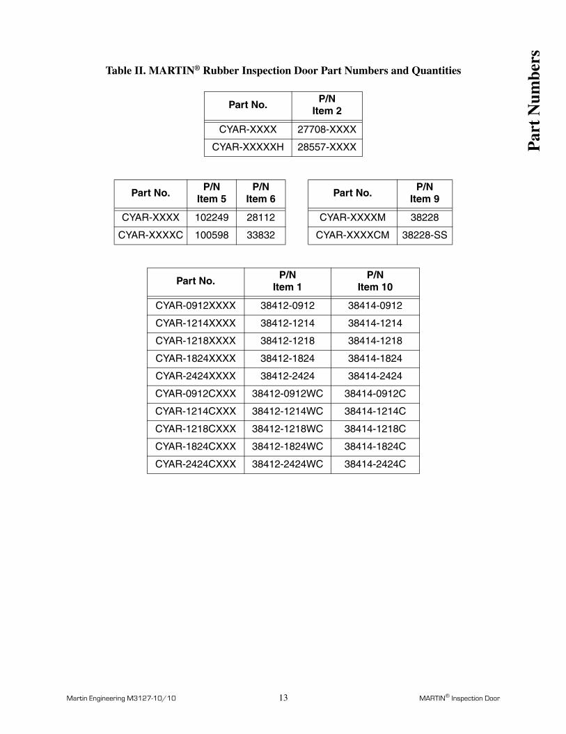
Table II. MARTIN® Rubber Inspection Door Part Numbers and Quantities
Part No. P/NItem 2
CYAR-XXXX 27708-XXXX
CYAR-XXXXXH 28557-XXXX
Part No.P/N
Item 5P/N
Item 6 Part No.P/N
Item 9
CYAR-XXXX 102249 28112 CYAR-XXXXM 38228
CYAR-XXXXC 100598 33832 CYAR-XXXXCM 38228-SS
Part No. P/NItem 1
P/NItem 10
CYAR-0912XXXX 38412-0912 38414-0912
CYAR-1214XXXX 38412-1214 38414-1214
CYAR-1218XXXX 38412-1218 38414-1218
CYAR-1824XXXX 38412-1824 38414-1824
CYAR-2424XXXX 38412-2424 38414-2424
CYAR-0912CXXX 38412-0912WC 38414-0912C
CYAR-1214CXXX 38412-1214WC 38414-1214C
CYAR-1218CXXX 38412-1218WC 38414-1218C
CYAR-1824CXXX 38412-1824WC 38414-1824C
CYAR-2424CXXX 38412-2424WC 38414-2424C
Par
t N
umbe
rs
Martin Engineering M3127-10/10 14 MARTIN® Inspection Door
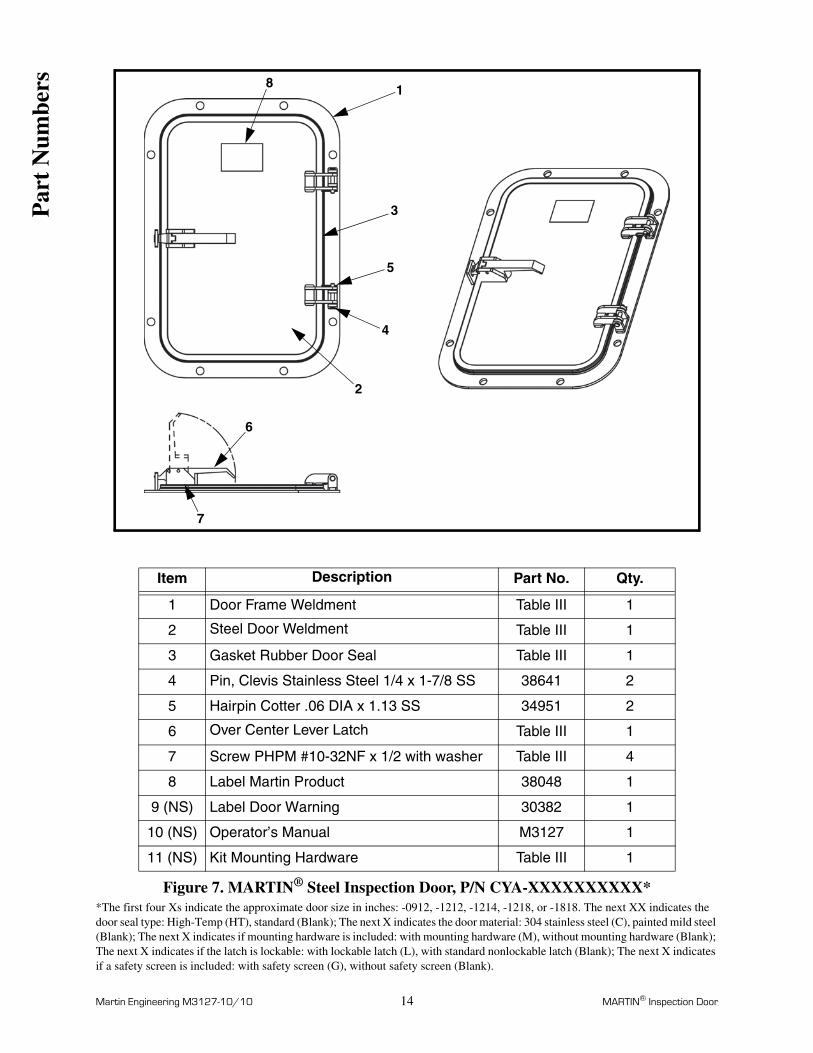
Figure 7. MARTIN® Steel Inspection Door, P/N CYA-XXXXXXXXXX**The first four Xs indicate the approximate door size in inches: -0912, -1212, -1214, -1218, or -1818. The next XX indicates the door seal type: High-Temp (HT), standard (Blank); The next X indicates the door material: 304 stainless steel (C), painted mild steel (Blank); The next X indicates if mounting hardware is included: with mounting hardware (M), without mounting hardware (Blank); The next X indicates if the latch is lockable: with lockable latch (L), with standard nonlockable latch (Blank); The next X indicates if a safety screen is included: with safety screen (G), without safety screen (Blank).
1
3
5
4
2
6
7
8
Item Description Part No. Qty.
1 Door Frame Weldment Table III 1
2 Steel Door Weldment Table III 1
3 Gasket Rubber Door Seal Table III 1
4 Pin, Clevis Stainless Steel 1/4 x 1-7/8 SS 38641 2
5 Hairpin Cotter .06 DIA x 1.13 SS 34951 2
6 Over Center Lever Latch Table III 1
7 Screw PHPM #10-32NF x 1/2 with washer Table III 4
8 Label Martin Product 38048 1
9 (NS) Label Door Warning 30382 1
10 (NS) Operator’s Manual M3127 1
11 (NS) Kit Mounting Hardware Table III 1
Par
t N
umbe
rs

Martin Engineering M3127-10/10 15 MARTIN® Inspection Door
Table III. MARTIN® Steel Inspection Door Part Numbers and Quantities
Part No. P/NItem 3**
CYA-0912XXXXXX 38400-0912
CYA-1212XXXXXX 38400-1212
CYA-1214XXXXXX 38400-1214
CYA-1218XXXXXX 38400-1218
CYA-1818XXXXXX 38400-1818
**For High-Temp seal add HT to end of part number.
Part No. P/NItem 6
Part No. P/NItem 7
Part No. P/NItem 11
CYA-XXXX 37051 CYA-XXXX 38182 CYA-XXXXM 38228
CYA-XXXXL 37051-L CYA-XXXXC M453-SS CYA-XXXXCM 38228-SS
Part No.P/N
Item 1P/N
Item 2
CYA-0912XXXXXX 38399-0912 38398-0912
CYA-1212XXXXXX 38399-1212 38398-1212
CYA-1214XXXXXX 38399-1214 38398-1214
CYA-1218XXXXXX 38399-1218 38398-1218
CYA-1818XXXXXX 38399-1818 38398-1818
CYA-0912XXCXXX 38399-0912WC 38398-0912WC
CYA-1212XXCXXX 38399-1212WC 38398-1212WC
CYA-1214XXCXXX 38399-1214WC 38398-1214WC
CYA-1218XXCXXX 38399-1218WC 38398-1218WC
CYA-1818XXCXXX 38399-1818WC 38398-1818WC
Par
t N
umbe
rs
Martin Engineering M3127-10/10 16 MARTIN® Inspection Door
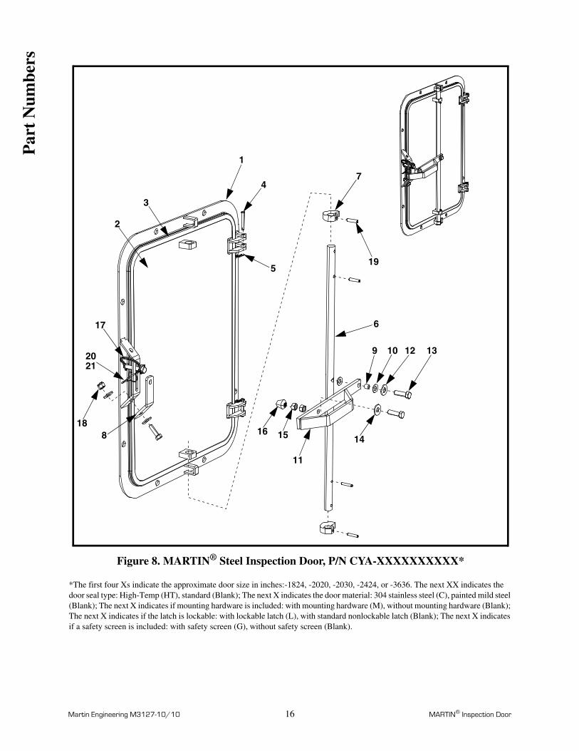
Figure 8. MARTIN® Steel Inspection Door, P/N CYA-XXXXXXXXXX*
*The first four Xs indicate the approximate door size in inches:-1824, -2020, -2030, -2424, or -3636. The next XX indicates the door seal type: High-Temp (HT), standard (Blank); The next X indicates the door material: 304 stainless steel (C), painted mild steel (Blank); The next X indicates if mounting hardware is included: with mounting hardware (M), without mounting hardware (Blank); The next X indicates if the latch is lockable: with lockable latch (L), with standard nonlockable latch (Blank); The next X indicates if a safety screen is included: with safety screen (G), without safety screen (Blank).
1
2
3
4
5
6
7
8
9
11
181516
12 13
17
19
2021
10
14
Par
t N
umbe
rs

Martin Engineering M3127-10/10 17 MARTIN® Inspection Door
Figure 8. MARTIN® Steel Inspection Door, P/N CYA-XXXXXXXXXX
Item Description Part No. Qty.
1 Door Frame Weldment Table IV 1
2 Steel Door Weldment Table IV 1
3 Gasket Rubber Door Seal Table IV 1
4 Pin, Clevis Stainless Steel 1/4 x 1-7/8 SS 38641 2
5 Hairpin Cotter .06 DIA x 1.13 SS 34951 2
6 Handle Rod Table IV 1
7 Cam Table IV 2
8 Bottom Latch Table IV 1
9 Spacer Table IV 1
10 Washer Nylon 9/16 38710 2
11 Handle Table IV 1
12 Washer Flat 5/16 Wide ZP Table IV 1
13 Screw HHC 3/8-16NC x 1-1/4 ZP Table IV 3
14 Washer Flat 3/8 Wide ZP Table IV 3
15 Nut Hex Jam 3/8-16NC ZP Table IV 2
16 Cushion Spindle Bottom 3/8 38570 1
17 Pin Wire Lock 3/8 x 1-3/4 Table IV 1
18 Nut Hex Elastic Lock 3/8-16NC ZP Table IV 1
19 Pin Slotted Spring 1/4 x 1-1/8 ZP Table IV 4
20 Cable Aircraft 1/16 dia 102249 1.5
21 Cable Clip 1/16 28112 2
22 (NS) Label Martin Product 38048 1
23 (NS) Label Martin Engineering Logo 22193-02 1
24 (NS) Label Door Warning 30382 1
25 (NS) Operator’s Manual M3127 1
26 (NS) Kit Mounting Hardware Table IV 1
Par
t N
umbe
rs
Martin Engineering M3127-10/10 18 MARTIN® Inspection Door
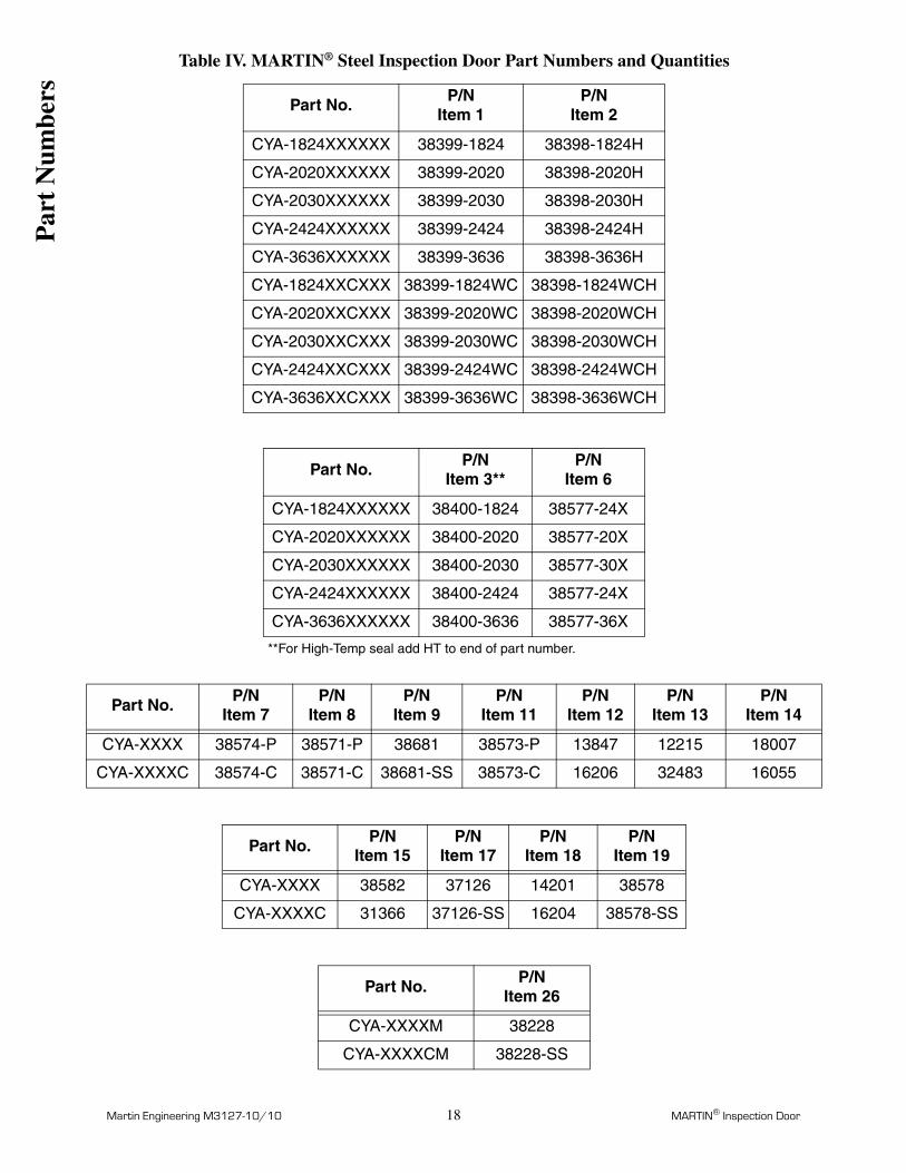
Table IV. MARTIN® Steel Inspection Door Part Numbers and Quantities
Part No. P/NItem 1
P/NItem 2
CYA-1824XXXXXX 38399-1824 38398-1824H
CYA-2020XXXXXX 38399-2020 38398-2020H
CYA-2030XXXXXX 38399-2030 38398-2030H
CYA-2424XXXXXX 38399-2424 38398-2424H
CYA-3636XXXXXX 38399-3636 38398-3636H
CYA-1824XXCXXX 38399-1824WC 38398-1824WCH
CYA-2020XXCXXX 38399-2020WC 38398-2020WCH
CYA-2030XXCXXX 38399-2030WC 38398-2030WCH
CYA-2424XXCXXX 38399-2424WC 38398-2424WCH
CYA-3636XXCXXX 38399-3636WC 38398-3636WCH
Part No. P/NItem 3**
P/NItem 6
CYA-1824XXXXXX 38400-1824 38577-24X
CYA-2020XXXXXX 38400-2020 38577-20X
CYA-2030XXXXXX 38400-2030 38577-30X
CYA-2424XXXXXX 38400-2424 38577-24X
CYA-3636XXXXXX 38400-3636 38577-36X
**For High-Temp seal add HT to end of part number.
Part No.P/N
Item 7P/N
Item 8P/N
Item 9P/N
Item 11P/N
Item 12P/N
Item 13P/N
Item 14
CYA-XXXX 38574-P 38571-P 38681 38573-P 13847 12215 18007
CYA-XXXXC 38574-C 38571-C 38681-SS 38573-C 16206 32483 16055
Part No. P/NItem 15
P/NItem 17
P/NItem 18
P/NItem 19
CYA-XXXX 38582 37126 14201 38578
CYA-XXXXC 31366 37126-SS 16204 38578-SS
Part No. P/NItem 26
CYA-XXXXM 38228
CYA-XXXXCM 38228-SS
Par
t N
umbe
rs

Martin Engineering M3127-10/10 19 MARTIN® Inspection Door
Figure 9. MARTIN® Extended-Height Steel Inspection Door, P/N CYAE-XXXX-XXXXXX**The first four Xs indicate the approximate door size in inches:-0912, -1214, -1218, -1824 or -2424. The next XX indicates the frame band height in inches: -03, -04, -05, -06, -07, -08, -09, -10, -11, or -12 (-08 is maximum height for -0912, -1214, and -1218 doors). The next X indicates the door material: 304 stainless steel (C), painted mild steel (Blank); The next X indicates if mounting hardware is included: with mounting hardware (M), without mounting hardware (Blank); The next X indicates if the latch is lockable: with lockable latch (L), with standard nonlockable latch (Blank); The next X indicates if a safety screen is included: with safety screen (G), without safety screen (Blank).
3
6
7
5
2
1
4
8
Item Description Part No. Qty.
1 Door Frame Weldment 38499-XXXX-XXXX 1
2 Steel Door Weldment Table V 1
3 Rubber Door Gasket Table V 1
4 Pin, Clevis Stainless Steel 1/4 x 1-5/8 38641 2
5 Hairpin Cotter 0.6 DIA x 1.13 SS 34951 2
6 Over Center Lever Latch Table V Table V
7 Screw PHPM #10-32NF x 1/2 w/washer Table V Table V
8 Label Martin Product 38048 1
9 (NS) Label Martin Engineering Logo 22193-02 Table V
10 (NS) Label Door Warning 30382 1
11 (NS) Operator’s Manual M3127 1
12 (NS) Kit Mounting Hardware Table V 1
13 (NS) Safety Screen Kit Table V 1
Par
t N
umbe
rs

Martin Engineering M3127-10/10 20 MARTIN® Inspection Door
Table V. MARTIN® Extended-Height Steel Inspection Door Part Numbers and Quantities
Part No.Qty
Item 6Qty
Item 7Qty
Item 9P/N
Item 3
CYAE-0912-XXXXXX 1 4 0 38400-0912
CYAE-1214-XXXXXX 1 4 0 38400-1214
CYAE-1218-XXXXXX 1 4 0 38400-1218
CYAE-1824-XXXXXX 2 8 1 38400-1824
CYAE-2424-XXXXXX 3 12 1 38400-2424
Part No. P/NItem 6
Part No. P/NItem 7
Part No. P/NItem 12
CYAE-XXXX-XXXX
37051CYAE-
XXXX-XXXX38182
CYAE-XXXX-XXXX
38228
CYAE-XXXX-XXLX
37051-LCYAE-
XXXX-XXCXM453-SS
CYAE-XXXX-XXCMX
38228-SS
Part No. P/NItem 2
P/NItem 13
CYAE-0912-XXXXXX 38398-0912 38409-0912
CYAE-1214-XXXXXX 38398-1214 38409-1214
CYAE-1218-XXXXXX 38398-1218 38409-1218
CYAE-1824-XXXXXX 38398-1824 38409-1824
CYAE-2424-XXXXXX 38398-2424 38409-2424
CYAE-0912-XXCXXX 38398-0912WC 38409-0912C
CYAE-1214-XXCXXX 38398-1214WC 38409-1214C
CYAE-1218-XXCXXX 38398-1218WC 38409-1218C
CYAE-1824-XXCXXX 38398-1824WC 38409-1824C
CYAE-2424-XXCXXX 38398-2424WC 38409-2424C
Par
t N
umbe
rs
Martin Engineering M3127-10/10 21 MARTIN® Inspection Door
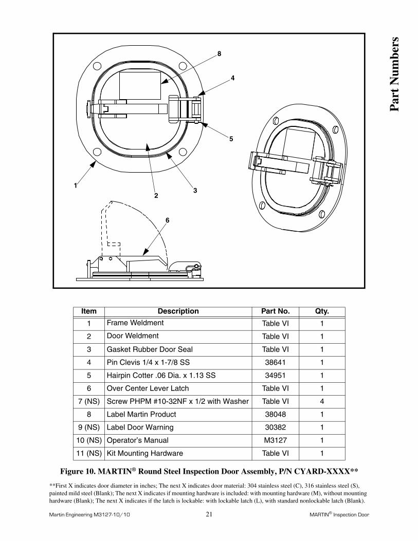
Figure 10. MARTIN® Round Steel Inspection Door Assembly, P/N CYARD-XXXX**
**First X indicates door diameter in inches; The next X indicates door material: 304 stainless steel (C), 316 stainless steel (S), painted mild steel (Blank); The next X indicates if mounting hardware is included: with mounting hardware (M), without mounting hardware (Blank); The next X indicates if the latch is lockable: with lockable latch (L), with standard nonlockable latch (Blank).
Item Description Part No. Qty.
1 Frame Weldment Table VI 1
2 Door Weldment Table VI 1
3 Gasket Rubber Door Seal Table VI 1
4 Pin Clevis 1/4 x 1-7/8 SS 38641 1
5 Hairpin Cotter .06 Dia. x 1.13 SS 34951 1
6 Over Center Lever Latch Table VI 1
7 (NS) Screw PHPM #10-32NF x 1/2 with Washer Table VI 4
8 Label Martin Product 38048 1
9 (NS) Label Door Warning 30382 1
10 (NS) Operator’s Manual M3127 1
11 (NS) Kit Mounting Hardware Table VI 1
8
4
5
32
1
6
Par
t N
umbe
rs

Martin Engineering M3127-10/10 22 MARTIN® Inspection Door
Table VI. MARTIN® Round Steel Inspection Door AssemblyPart Numbers and Quantities
Part Number Item 1P/N
Item 2P/N
CYARD-4XXX 38639-4 38638-4
CYARD-6XXX 38639-6 38638-6
CYARD-8XXX 38639-8 38638-8
CYARD-4CXX 38639-4WC 38638-4WC
CYARD-6CXX 38639-6WC 38638-6WC
CYARD-8CXX 38639-8WC 38638-8WC
CYARD-4SXX 38639-4WS 38638-4WS
CYARD-6SXX 38639-6WS 38638-6WS
CYARD-8SXX 38639-8WS 38638-8WS
Part NumberItem 3
P/N Part NumberItem 6
P/N
CYARD-4XXX 38400-4 CYARD-X 37051
CYARD-6XXX 38400-6 CYARD-XL 37051-L
CYARD-8XXX 38400-8
Part Number Item 7P/N
Part Number Item 11P/N
CYARD-X 38182 CYARD-XM 38228-04
CYARD-XC M453-SS CYARD-XCM 38228-04SS
CYARD-XS M453-SS CYARD-XSM 38228-04SS
Par
t N
umbe
rs

Martin Engineering M3127-10/10 A-1 MARTIN® Inspection Door
MARTIN® Inspection Door Warning Label, P/N 30382
Appendix AMARTIN® Inspection Door Label
App
endi
x A

Notes
Martin Engineering M3127-10/10 B-1 MARTIN® Inspection Door
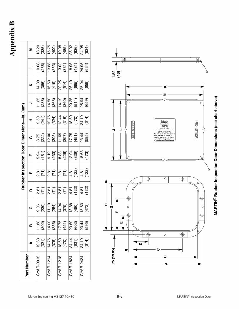
Appendix BMARTIN® Inspection Door Dimensions
App
endi
x B
Martin Engineering M3127-10/10 B-2 MARTIN® Inspection Door
AB
C
D
EF
G
H
.75
(19.
05)
1.82
LJ
MK
Par
t N
um
ber
Ru
bb
er In
spec
tio
n D
oo
r D
imen
sio
ns—
in. (
mm
)
AB
CD
EF
GH
JK
LM
CYA
R-0
912
12.6
3 (3
21)
11.8
8 (3
02)
9.06
(2
30)
2.81
(7
1)2.
81
(71)
5.94
(1
51)
8.75
(2
22)
9.50
(2
41)
11.2
5 (2
86)
14.3
8 (3
65)
10.0
8 (2
56)
13.2
0 (3
35)
CYA
R-1
214
14.7
5 (3
75)
14.0
0 (3
56)
11.1
9 (2
84)
2.81
(7
1)2.
81
(71)
9.19
(2
33)
12.0
0 (3
05)
12.7
5 (3
24)
14.5
0 (3
68)
16.5
0 (4
19)
13.8
8 (3
53)
15.7
5 (4
00)
CYA
R-1
218
18.5
0 (4
70)
17.7
5 (4
51)
14.9
4 (3
79)
2.81
(7
1)2.
81
(71)
8.88
(2
26)
11.6
9 (2
97)
12.4
4 (3
16)
14.1
9 (3
60)
20.2
5 (5
14)
13.0
2 (3
31)
19.0
8 (4
85)
CYA
R-1
824
24.4
4 (6
21)
23.6
9 (6
02)
18.8
8 (4
80)
4.81
(1
22)
4.81
(1
22)
12.9
4 (3
29)
17.7
5 (4
51)
18.5
0 (4
70)
20.2
5 (5
14)
26.1
9 (6
65)
18.9
5 (4
81)
25.0
2 (6
36)
CYA
R-2
424
24.1
9 (6
14)
23.4
4 (5
95)
18.6
3 (4
73)
4.81
(1
22)
4.81
(1
22)
18.6
3 (4
73)
23.4
4 (5
95)
24.1
9 (6
14)
25.9
4 (6
59)
25.9
4 (6
59)
24.9
5 (6
34)
24.9
5 (6
34)
(46)
MA
RT
IN®
Ru
bb
er In
spec
tio
n D
oo
r D
imen
sio
ns
(see
ch
art
abo
ve)
App
endi
x B
Martin Engineering M3127-10/10 B-3 MARTIN® Inspection Door
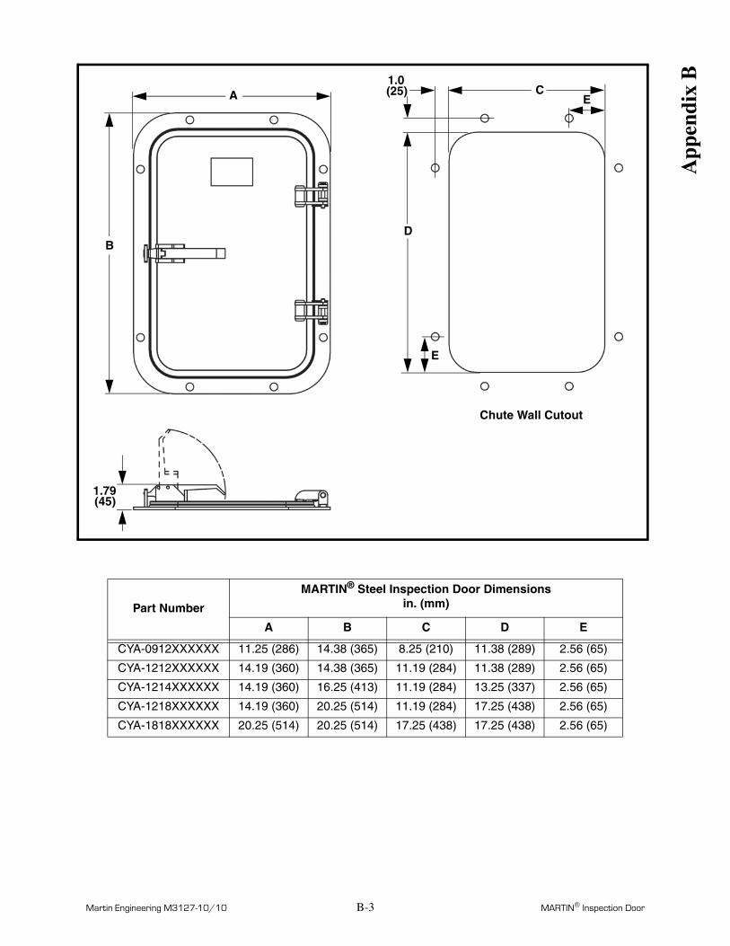
Part Number
MARTIN® Steel Inspection Door Dimensionsin. (mm)
A B C D E
CYA-0912XXXXXX 11.25 (286) 14.38 (365) 8.25 (210) 11.38 (289) 2.56 (65)
CYA-1212XXXXXX 14.19 (360) 14.38 (365) 11.19 (284) 11.38 (289) 2.56 (65)
CYA-1214XXXXXX 14.19 (360) 16.25 (413) 11.19 (284) 13.25 (337) 2.56 (65)
CYA-1218XXXXXX 14.19 (360) 20.25 (514) 11.19 (284) 17.25 (438) 2.56 (65)
CYA-1818XXXXXX 20.25 (514) 20.25 (514) 17.25 (438) 17.25 (438) 2.56 (65)
EC
1.0(25)
D
E
B
A
1.79(45)
Chute Wall Cutout
App
endi
x B

Martin Engineering M3127-10/10 B-4 MARTIN® Inspection Door
Part Number
MARTIN® Steel Inspection Door Dimensionsin. (mm)
A B C D E
CYA-1824XXXXXX 20.25 (514) 26.19 (665) 17.25 (438) 23.19 (589) 4.56 (116)
CYA-2020XXXXXX 22.25 (565) 22.25 (565) 19.25 (489) 19.25 (489) 4.56 (116)
CYA-2424XXXXXX 25.94 (659) 25.94 (659) 22.94 (583) 22.94 (583) 4.56 (116)
EC
1.0(25)
D
E
B
A
Chute Wall Cutout
4.11(104)
App
endi
x B
Martin Engineering M3127-10/10 B-5 MARTIN® Inspection Door
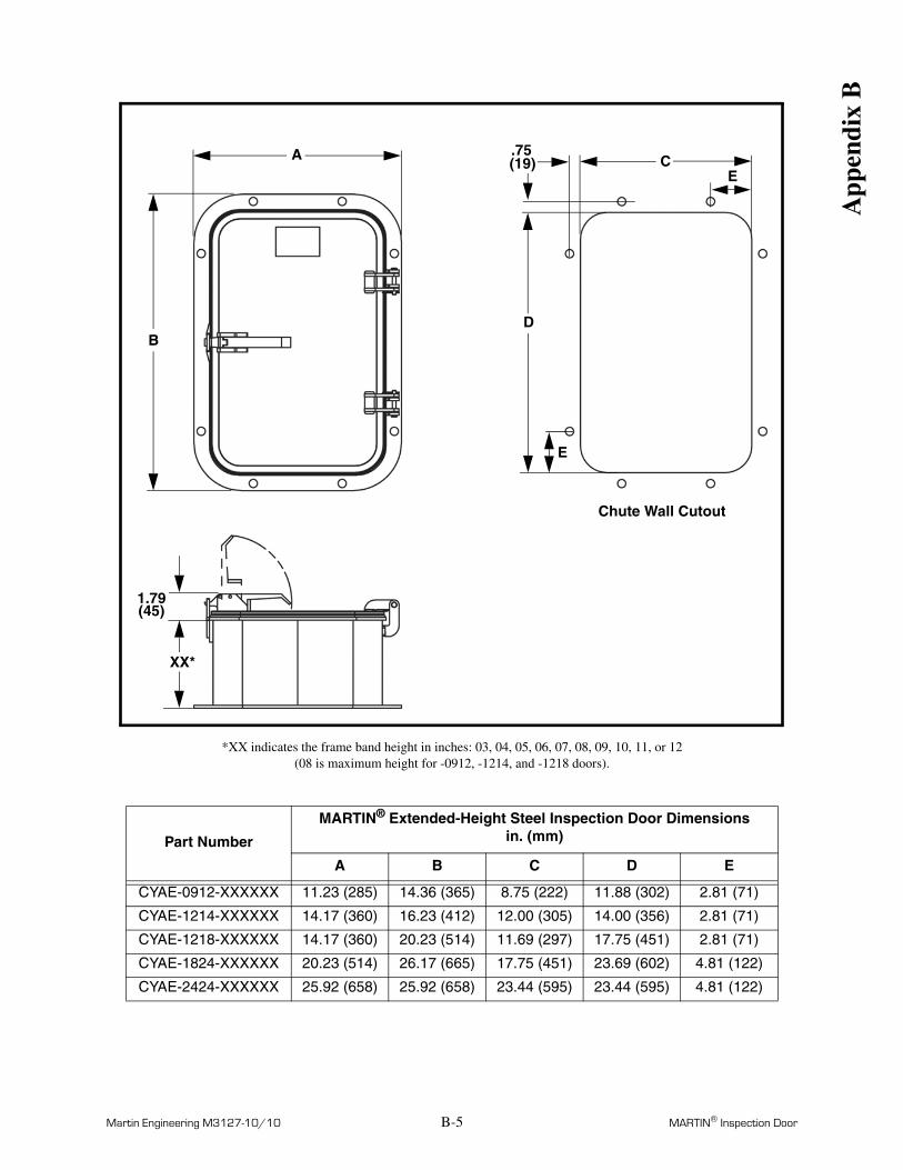
*XX indicates the frame band height in inches: 03, 04, 05, 06, 07, 08, 09, 10, 11, or 12 (08 is maximum height for -0912, -1214, and -1218 doors).
Part Number
MARTIN® Extended-Height Steel Inspection Door Dimensionsin. (mm)
A B C D E
CYAE-0912-XXXXXX 11.23 (285) 14.36 (365) 8.75 (222) 11.88 (302) 2.81 (71)
CYAE-1214-XXXXXX 14.17 (360) 16.23 (412) 12.00 (305) 14.00 (356) 2.81 (71)
CYAE-1218-XXXXXX 14.17 (360) 20.23 (514) 11.69 (297) 17.75 (451) 2.81 (71)
CYAE-1824-XXXXXX 20.23 (514) 26.17 (665) 17.75 (451) 23.69 (602) 4.81 (122)
CYAE-2424-XXXXXX 25.92 (658) 25.92 (658) 23.44 (595) 23.44 (595) 4.81 (122)
EC
.75(19)
D
E
B
A
Chute Wall Cutout
1.79(45)
XX*
App
endi
x B
Martin Engineering M3127-10/10 B-6 MARTIN® Inspection Door
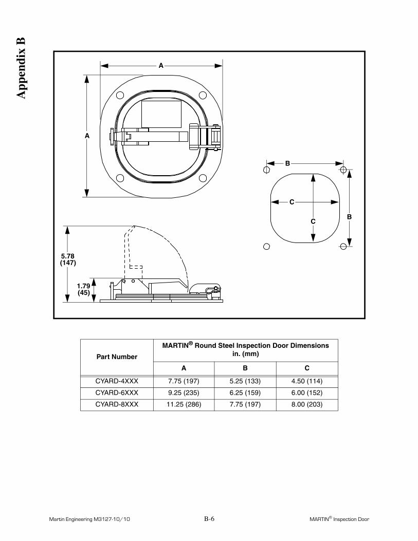
Part Number
MARTIN® Round Steel Inspection Door Dimensionsin. (mm)
A B C
CYARD-4XXX 7.75 (197) 5.25 (133) 4.50 (114)
CYARD-6XXX 9.25 (235) 6.25 (159) 6.00 (152)
CYARD-8XXX 11.25 (286) 7.75 (197) 8.00 (203)
1.79(45)
5.78(147)
A
A
C
C
B
B
App
endi
x B

Any product, process, or technology described here may be the subject of intellectual property rights reserved by Martin Engineering Company. Trademarks or service marks designated with the ® symbol are registered with the U.S. Patent and Trademark Office and may be proprietary in one or more countries or regions. Other trademarks and service marks belonging to Martin Engineering Company in the United States and/or other countries or regions may be designated with the “TM” and “SM” symbols. Brands, trademarks, and names of other parties, who may or may not be affiliated with, connected to, or endorsed by Martin Engineering Company, are identified wherever possible. Additional information regarding Martin Engineering Company’s intellectual property can be obtained at www.martin-eng.com/trademarks.
Martin Engineering USAOne Martin PlaceNeponset, IL 61345-9766 USA800 544 2947 or 309 852 2384Fax 800 814 1553www.martin-eng.com
Subject to change without prior notice.Quality Management System Certified by DNV - ISO 9001
Form No. M3127-10/10 © Martin Engineering Company 1984, 2010


