43
MARTIN ® QB TM #1 Heavy-Duty Pre-cleaner Installation instructions M4022UK

MARTIN® QBTM #1 Heavy-DutyPre-cleaner
Installation instructionsM4022UK

© Martin Engineering GmbH M4022UK-01/15

Tab
le of co
nten
ts
1 Table of contents
1 Table of contents ............................................................. 12 Introduction ...................................................................... 32.1 About these operating instructions..................................... 32.1.1 Scope ............................................................................ 32.1.2 Copyright ....................................................................... 32.1.3 Exclusion of liability ....................................................... 32.1.4 Reference to additional documents ............................... 42.1.5 Classification of the hazards.......................................... 52.2 Intended use ...................................................................... 62.2.1 Conveyor systems with open transfer systems ............. 62.2.2 Usage in explosion-protected areas ............................. 62.2.3 Restrictions on the use of the product ........................... 72.3 Occupational safety............................................................ 72.3.1 Safety information, occupational safety ......................... 72.3.2 Duties of the owner-operator ......................................... 82.3.3 Authorised personnel...................................................... 83 Description of the product .............................................. 93.1 Design and function ........................................................... 93.2 Inline Reversing tensioners ................................................ 93.3 Type clarification .............................................................. 104 Preparing for the installation ........................................ 114.1 Prior to the installation...................................................... 114.1.1 Required materials and tools........................................ 114.1.2 Preparatory measures ............................................................. 115 Installation ...................................................................... 135.1 Safety information ............................................................ 135.2 Installation process .......................................................... 145.2.1 Determination of the installation position ..................... 145.2.2 Installation of the Inline Reversing tensioner ............... 175.2.3 Installation of the pre-cleaner ...................................... 185.2.4 Centring the mainframe beneath the conveyor belt..... 215.2.5 Aligning the mainframe in parallel to the conveyor belt 215.2.6 Aligning the mainframe horizontally............................. 225.2.7 Tightening the pre-cleaner............................................ 225.3 Operation under load ....................................................... 245.4 Installation - Check list ..................................................... 255.5 Placement of the warning labels and warning trailers...... 266 Maintenance .................................................................... 276.1 Safety information ............................................................ 276.2 Weekly Maintenance......................................................... 276.3 Replacement of the blades .............................................. 297 Troubleshooting ............................................................. 317.1 Safety information ............................................................ 317.2 Troubleshooting ............................................................... 318 Storage, deinstallation, disposal .................................. 338.1 Storage............................................................................. 33
© Martin Engineering GmbH 1 M4022UK-01/15

Tab
le o
f co
nte
nts
8.2 Deinstallation .................................................................... 338.3 Disposal ............................................................................ 339 Part numbers ...................................................................349.1 Explanation of part numbers............................................. 349.2 Inline Reversing tensioner ................................................359.3 MARTIN® Inspection Doors .............................................. 359.4 Installation instructions.......................................................359.5 Accessories....................................................................... 369.6 Warning labels / Warning trailers 369.7 MARTIN® QB™ #1 Heavy-Duty Pre-Cleaner ................... 3710 Declaration of incorporation ..........................................40
© Martin Engineering GmbH 2 M4022UK-01/15
Intro
du
ction
2 Introduction
2.1 About these installation instructions
Non-compliance with these installation instructions can result in loss of compensation for damage and/or warranty claims.
2.1.1 Scope
These installation instructions apply solely for the product described herein and are intended for those persons who install this product, commission it, and monitor its usage.
2.1.2 Copyright
The products described and these installation instructions are protected by copyright. Any reproduction without a license will be prosecuted. All rights to the present document are reserved, including its reproduction and/or copying in any conceivable manner. Reprints of this document require the written consent of Martin Engineering.
The technical standard at the time of delivery of the product and its technical documentation is decisive for as long as no other information is provided. The product and documentation are subject to technical changes without prior notification. Earlier documents then lose their validity. Martin Engineering’s General Terms of Sales and Delivery shall apply.
2.1.3 Exclusion of liability
Martin Engineering guarantees the flawless function of its product in accordance with its advertising, the published product information, and its technical documentation. Martin Engineering shall assume no liability for efficiency and flawless function if the product is used for a purpose other than that described in the “Intended Use” section or for damage resulting from the use of accessories and/or spare parts which were not supplied and/or certified by Martin Engineering.
© Martin Engineering GmbH 3 M4022UK-01/15

Intr
od
uct
ion
The Martin Engineering products are designed for a long service life.They conform to the state of the art in science and technology and were thoroughly inspected before shipment. In addition to this, Martin Engineering constantly performs product and market research for continuous product development.
Martin Engineering offers competent support whenever malfunctions and/or technical problems occur. Suitable actions are taken immediately. The warranty provisions of Martin Engineering apply and can be sent to you as needed.
2.1.4 Reference to additional documents
Reference is made in these installation instructions to the following documents:
• Installation instructions for the MARTIN® Inspection door, Publication no. M3127.
• Installation instructions for the MARTIN® TWIST™ Inline tensioners, Publication no. M3296.
• Installation instructions for the MARTIN® spring and air tensioner, Publication no. M3263.
• Installation instructions for the MARTIN® SG1S spring tensioner, Publication no. M3766
The following standards and directives were complied with in the preparation of these installation instructions:
• EU Machinery Directive (2006/42/EC)
• ISO/IEC Guide 37 “Installation instructions for products used by final consumers”, 1995 Edition
• DIN 1421 “Organisation and numbering in texts”, Edition 1983-01
• DIN/EN 12100 “Machine safety - basic definitions, general design guidelines”, Edition 2013-08
• DIN/ISO 16016 “Technical product documentation - Protection notices for restricting the use of documents and products”, Edition 2007-12
• DIN/EN 60204-1 “Safety of machines - Electrical Equipment of Machines, Part1 General requirements”, Edition 2007-06
• DIN EN 82079-1 - Creation of user manuals - Structuring, content and presentation, Part 1 General principles and detailed requirements.
© Martin Engineering GmbH 4 M4022UK-01/15

Intro
du
ction
2.1.5 Classification of the hazards
DANGER!
Represents an immediately threatening danger which leads toserious bodily injuries or death if not avoided.
WARNING!
Represents a possibly hazardous situation which could lead toserious bodily injuries or death if not avoided.
CAUTION!
Represents a possibly hazardous situation which could lead tominor bodily injuries and/or property damage if not avoided.
NOTE
Contains comments about the installation and/or the product’susage to point out situations which cause neither personal injurynor property damage but include important information.
© Martin Engineering GmbH 5 M4022UK-01/15

Intr
od
uct
ion
2.2 Intended usageDer MARTIN® QB™ #1 Heavy-Duty pre-cleaner is used exclusively for the cleaning of conveyor belts. These can have a belt width of up to 2400 mm and a belt speed of up to 4.6 m/s. The pre-cleaner can be directly installed on the head pulley.
Every other usage of this product is deemed misuse. Please contact Martin Engineering customer service if you would like to use this product for a different purpose. We will be happy to assist you with the product configuration.
2.2.1 Conveyor systems with open transfer systems
These installation instructions describe the installation on conveyor systems with encapsulated transfer systems. Various MARTIN® Inline mount plates can be used on open transfer systems.
Martin Engineering or one of its representatives can assist with the position or with special solutions in cases where the installation conditions are complicated such as insurmountable static components or a head pulley as the tensioning station.
2.2.2 Usage in explosion-protected areas
This product can also be used in potentially explosive areas under certain conditions. Contact Martin Engineering for more information on usage in potentially explosive areas.
The cleaner must not be used in a higher equipment protection category or under other operating conditions than those specified by Martin Engineering unless such usage has been approved by Martin Engineering.
© Martin Engineering GmbH 6 M4022UK-01/15

Intro
du
ction
2.2.3 Restrictions on the use of the product
The product specified here may only be used within the scope of the specifications referred to above. Usage in a higher equipment protection category or under other operating conditions than those specified by Martin Engineering shall be deemed misuse and is only permitted if approved by Martin Engineering.
Martin Engineering or one of its representatives can assist you with the product configuration if you need to use this product for a different purpose.
2.3 Occupational safety
2.3.1 Safety information, occupational safety
These installation instructions must be read through in their entirety before work may be started on the product or on the conveyor system supplied by the customer.
The owner-operator must ensure that all installation, inspection and maintenance work is performed solely by trained specialists.
Work on conveyor systems and their accessories must always be performed during shut-down. The procedures described in the applicable installation instructions for shutting down the conveyor system must always be complied with.
All of the safety devices and safeguards must be reattached and/or made operational immediately following completion of the work.
The installation must be carried out to completion before the system is started up. The flawless execution of all operating steps must be tested before the conveyor system can be started up again. Please observe all information on the installation and start-up of the product.
© Martin Engineering GmbH 7 M4022UK-01/15

Intr
od
uct
ion
2.3.2 Duties of the owner-operatorThis product’s owner-operator must ensure that this product is installed, serviced and used solely by those persons who
• know the rules regarding occupational safety and accident prevention,
• were trained on using this product and have read and understood these installation instructions.
2.3.3 Authorised personnel
Personnel are considered authorised when they have suitable training and technical experience, can demonstrate knowledge of the applicable standards and guidelines, and are able to evaluate tasks in order to recognise critical situations at an early stage.
Operating, maintenance and installation personnel
Personnel are considered authorised when they have been trained on using the product and have read and understood these operating instructions in their entirety.
© Martin Engineering GmbH 8 M4022UK-01/15

Descrip
tion
of th
e pro
du
ct
3 Description of the product
3.1 Design and function
The MARTIN® QB™ #1 Heavy-Duty belt cleaner is designed for the most difficult applications and allows blades to be changed simply by removing a single pin wire lock. The installation position of the pre-cleaner on the head pulley (e.g. QC™ #2) immediately downstream of the head pulley guarantees that the cleaned off material is returned to the material flow.
Although pre-cleaners and secondary cleaners can each be used individually, the installation of a system consisting of pre-cleaners and secondary cleaners is recommended for an optimal cleaning result.
3.2 Inline Reversing tensioners
The MARTIN® QB™ #1 Heavy-Duty pre-cleaner and the Martin Engineering Inline Reversing tensioners, which are specially developed for it, offer the best possible results and correspond to the general state of the art.
Martin Engineering recommends the following Inline Reversing tensioners for the MARTIN® QB™ #1 Heavy-Duty pre-cleaner:
• MARTIN® TWIST™ Inline tensioner:Part number 31443-XI+E or 38850-X.
• MARTIN® Spring tensioner:Part number 38180-X.
• MARTIN® SG1S Spring tensioner:Part number SG1S-T+I.
NOTE
An unfavourable or improperly installed product can disrupt theconveyor process or contaminate the bulk material to betransported.The owner-operator is responsible for taking the requiredcountermeasures.In the case of applications with contaminants, Martin Engineeringor one of its representatives can assist with the positioning or withspecial solutions.
© Martin Engineering GmbH 9 M4022UK-01/15

Des
crip
tio
n o
f th
e p
rod
uct
3.3 Type clarificationBlades for the MARTIN® QB™ #1 Heavy-Duty pre-cleaner are available in various material designs. The required material can be selected in accordance with the material conditions. The selection of the various blade materials is listed in the “Part numbers” section.
© Martin Engineering GmbH 10 M4022UK-01/15

Prep
aring
for th
e installatio
n
4 Preparing for the installation
4.1 Before the installation
4.1.1 Required materials and tools
Along with the standard tools, the following special equipment may be needed for the installation and maintenance of your product.
• Lifting device with a capacity greater than the weight of the belt cleaner (see delivery note for weight data).
4.1.2 Preparatory measures
1. Inspect the delivery for the following conditions:
• Is the delivery complete? Does the number of pallets/crates/containers delivered match the number on the delivery note?
• Do all of the transport packages appear to be undamaged? Does damage to the packaging exist which indicates damage to the product contained inside?
NOTE
Perform the inspections described carefully and completely.The shipping company is liable for any transport damage! Please contact the shipper with any damage claims.
NOTE
An unfavourable or improperly installed product can disrupt theconveyor process or contaminate the bulk material to betransported.The owner-operator is responsible for taking the requiredcountermeasures.In the case of applications with contaminants, please seek theadvice of Martin Engineering orone of its representatives.
© Martin Engineering GmbH 11 M4022UK-01/15

Pre
par
ing
fo
r th
e in
stal
lati
on
2. Always record any incompleteness or transport damagediscovered in the delivery and have it confirmed by the shipper. All damaged products must be kept for inspection.
3. The delivery should include the following parts, depending on the scope of the order:
• MARTIN® QB™#1 Heavy-Duty Pre-Cleaner,
• possible accessories as contained in the order,
• two Conveyor Products Warning Labels Part No. 23395.
4. Report any missing or damaged parts to Martin Engineering or one of its contracted dealers.
© Martin Engineering GmbH 12 M4022UK-01/15

Installatio
n
5 Installation
5.1 Safety information
NOTE
Read this section completely before starting any kind of work!
WARNING! RISK OF INJURY!
Body parts and/or clothing can be pulled in by rotatingcomponents or the moving conveyor belt.Shut off the power supply to the conveyor system and itsaccessories and secure it against unauthorised reactivation beforeperforming any installation or maintenance work. Post warningsigns!
WARNING! RISK OF EXPLOSION!
Increased risk when using a cutting torch or welding device inclosed rooms!Check the gas and dust content of the air before usage.
NOTE
The chute wall on which the Inline-Reversing tensioner is to beinstalled is designated as the “operator side”. The other chute wallis designated as the “far side”.When dual Inline-Reversing tensioners are installed, the easiestside to access is the “operator side”.
© Martin Engineering GmbH 13 M4022UK-01/15

Inst
alla
tio
n
5.2 Installation process5.2.1 Determination of the installation position
The position of the mainframe and Inline-Reversing tensioner of the MARTIN® QB™ #1 Heavy-Duty pre-cleaner must be determined on both sides of the chute wall. In this process, the positions are determined where the mainframe of the MARTIN® QB™ #1 Heavy-Duty pre-cleaner is routed through the chute wall and where the Inline-Reversing tensioner is installed on the chute wall.
The MARTIN® QB™ #1 Heavy-Duty pre-cleaner is operated together with an Inline-Reversing tensioner. This is not installed in the delivery state and is installed together with the pre-cleaner during the general installation.
The installation of the MARTIN® QB™ #1 Heavy-Duty pre-cleaner and the Inline-Reversing tensioner is described in these installation instructions and in those of the Inline-Reversing tensioner.
An overview of the installation steps follows:
Various on-site conditions requiring different work steps are possible for the installation. These are presented as follows:
Installation on an encapsulated transfer system
• Follow the instructions given in Section 5.2.2.
Installation on an encapsulated transfer system with pre-existing installation openings and air line brackets for belt cleaners.
• Follow the instructions given in Section 5.2.3.
Installation on an open transfer system
• Use the equipment provided at the site to comply with the dimensions for correct installation.
No. Installation step Instructions
1 Positioning the pre-cleaner mainframe
M4022
2 Installing the pre-cleaner M4022
3 Installing the Inline-Reversing tensioner
M3296 or M3263 or M3766
4 Installing the blade M4022
Tab. 1: Installation steps
© Martin Engineering GmbH 14 M4022UK-01/15

Installatio
n
1. Deactivate the conveyor system and all accessories before starting the installation work and secure them against unauthorised reactivation.
2. Determine the position of the mainframe centre for the pre-cleaner as described in the following.
3. Mark the vertical and horizontal centre line of the driving drum on the operator side of the chute wall to determine the centre point (1, Fig. 1) of the driving drum. The vertical line must run at a right angle with respect to the conveyor belt line.
4. Determine and/or measure the radius (Dimension A) of the driving drum together with the thickness of the coating and the conveyor belt.
NOTE
The MARTIN® QB™ #1 Heavy-Duty pre-cleaner is installedexclusively in the lower front quarter of a head pulley. Alwayscomply with the specified installation dimensions.
Fig. 1: Marking of the installation radius
NOTE
Martin Engineering recommends installing a MARTIN®inspectiondoor for the purpose of better accessibility for maintenance andrepairs.
A + X
1
© Martin Engineering GmbH 15 M4022UK-01/15

Inst
alla
tio
n
5. Add dimension X from Table 2 to Dimension A. 6. Draw the arc of a circle with the dimension determined in step
5 around the centre of the chute wall (1, Fig. 1).
7. Mark a horizontal line at a distance of 216 mm beneath the horizontal centre line of the head pulley. The cutting point with the arc marked in step 5 is the centre of the mainframe (3, Fig. 2).
Pulley diameter in mm Dimension X in mm
300 - 475 102
> 475 89
*incl. rubber coating and conveyor belt
Tab. 2: X-values for the positioning of the mainframe
Fig. 2: Marking of the installation height
WARNING! RISK OF INJURY!
The pre-cleaner is heavy and can cause serious injuries if it isdropped during lifting or moving.Always use a suitable lifting device or engage the help of severalpersons when lifting the pre-cleaner. Do not stand under hangingloads.
90°
90°
min.210 mm
3
© Martin Engineering GmbH 16 M4022UK-01/15

Installatio
n
8. Repeat steps 1 to 6 on the far side of the chute wall.
5.2.2 Installing the Inline-Reversing tensioner
Follow the instructions for installing your Inline-Reversing tensioner in accompanying installation manual. (See sections 2.1.4).
NOTE
This is the best possible installation position and thatrecommended by Martin Engineering for achieving an optimal
cleaning result with the MARTIN® QB™ #1 Heavy-Duty pre-cleaner. If structural conditions make this impossible, then the pre-cleaner can also be installed in consultation with MartinEngineering at an angle of 20° upwards or downwards, with theinstallation radius being complied with in all cases.
© Martin Engineering GmbH 17 M4022UK-01/15

Inst
alla
tio
n
5.2.3 Installing the pre-cleanerFig. 3: Removing the blade
NOTE
The numbering of the parts in the following sections is based onthe item numbers of the parts list from the parts numbers section.
4
2
7 1
© Martin Engineering GmbH 18 M4022UK-01/15

Installatio
n
1. First remove the blade from the mainframe as described in the following:
• Open the pin hitch (7, Fig. 3) and remove it from the mainframe (1, Fig. 3).
• Pull the blade stop (4 or 3, Fig. 3) out of the mainframe from the side.
• Pull the blade (2, Fig. 3) laterally out of the blade stop on the far side and then pull it upwards and out.
2. Install the telescope axles (5 and 6, Fig.4) on both sides of the chute in the previously installed Inline-Reversing tensioner.
Fig. 4: Installing the mainframe
NOTE
The telescope axle is an individual continuous axle for belt widthsof 84 (2200) or greater. Therefore the telescope axle must first beinserted into the mainframe (1, Fig. 4) for belt widths of this size orgreater and both frames must be installed together in the Inline-Reversing tensioner.
1
95
© Martin Engineering GmbH 19 M4022UK-01/15

Inst
alla
tio
n
3. Slide the two blade stops (4 and 3, Fig. 3) onto the right and left sides of the mainframe (1, Fig. 3).4. Slide the mainframe (1, Fig. 4) onto the telescope axle(5, Fig. 4) on one side and then slide it onto the telescope axle on the far side.
5. Do not lock the mainframe yet, but place the blade (2, Fig. 3) on the mainframe.
6. Perform Step 1 in reverse order.
NOTE
Ensure in this process that the blade is positioned in a way that itstip points against the conveyor belt.
© Martin Engineering GmbH 20 M4022UK-01/15

Installatio
n
5.2.4 Centring the mainframe beneath the conveyor belt
Measure the clearances (A) and (B) between the edge of the cleaning elements and the conveyor belt edge.
Shift the cleaner so that clearance A is equal to clearance B. The conveyor belt must protrude around 50 to 100 mm from the left and right sides. The blade must be centrally aligned beneath the conveyor belt.
5.2.5 Aligning the mainframe in parallel to the conveyor belt
Measure the clearance on both sides between the blade and the head pulley. Place the blade onto the conveyor belt for this. The measurements must be the same on both sides
Fig. 5: Centring the mainframe (for example)
Fig. 6: Aligning the mainframe in parallel to the head pulley (as an example)
A = BA B
B
A = BBA
A
A = B
© Martin Engineering GmbH 21 M4022UK-01/15
Inst
alla
tio
n
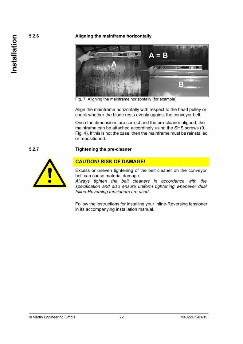
5.2.6 Aligning the mainframe horizontallyAlign the mainframe horizontally with respect to the head pulley or check whether the blade rests evenly against the conveyor belt.
Once the dimensions are correct and the pre-cleaner aligned, the mainframe can be attached accordingly using the SHS screws (9, Fig. 4). If this is not the case, then the mainframe must be reinstalled or repositioned.
5.2.7 Tightening the pre-cleaner
Follow the instructions for installing your Inline-Reversing tensioner in its accompanying installation manual.
Fig. 7: Aligning the mainframe horizontally (for example)
CAUTION! RISK OF DAMAGE!
Excess or uneven tightening of the belt cleaner on the conveyorbelt can cause material damage.Always tighten the belt cleaners in accordance with thespecification and also ensure uniform tightening whenever dualInline-Reversing tensioners are used.
A
B
A = B
© Martin Engineering GmbH 22 M4022UK-01/15
Installatio
n
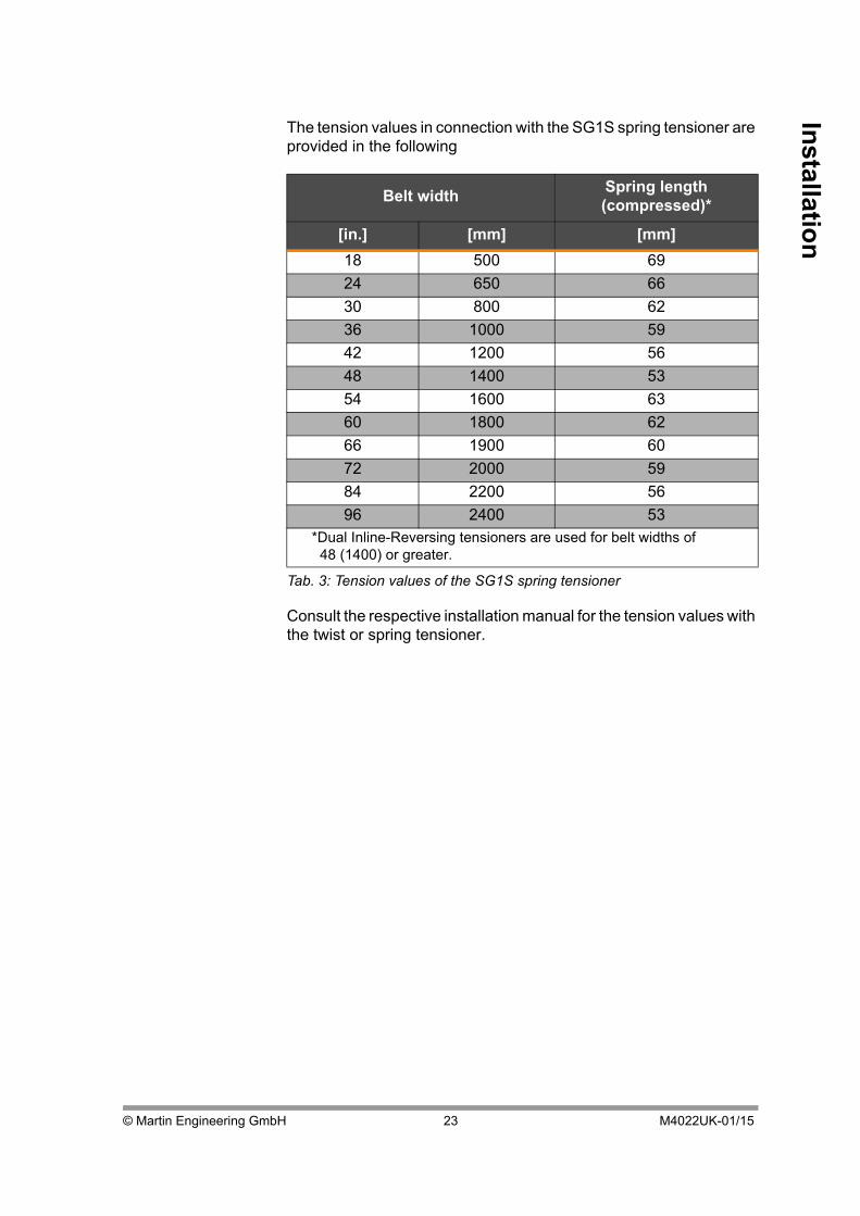
The tension values in connection with the SG1S spring tensioner are provided in the following
Consult the respective installation manual for the tension values with the twist or spring tensioner.
Belt width Spring length (compressed)*
[in.] [mm] [mm]
18 500 69
24 650 66
30 800 62
36 1000 59
42 1200 56
48 1400 53
54 1600 63
60 1800 62
66 1900 60
72 2000 59
84 2200 56
96 2400 53*Dual Inline-Reversing tensioners are used for belt widths of
48 (1400) or greater.
Tab. 3: Tension values of the SG1S spring tensioner
© Martin Engineering GmbH 23 M4022UK-01/15

Inst
alla
tio
n
5.3 Operation with loading1. Remove all tools and fire protection covers from the installation site and the conveyor belt.
2. Operate the conveyor system for 1 hour under load.
3. Shut off the conveyor system after the 1-hour operation under load, shut off the power supply and secure it against unauthorized reactivation.
4. Check whether all of the fastening points are securely tightened. Tighten any loose connections.
NOTE
Read through this section completely before starting any work onthe belt cleaner or on the customer’s conveyor system.
CAUTION! FLYING OBJECTS!
Forgotten tools or installation parts can fall off of the runningconveyor belt and cause minor injuries and property damage.Always remove any tools from the installation site and conveyorbelt upon completion of the installation work before switching onthe power supply.
WARNING! RISK OF INJURY!
Body parts and/or clothing can be pulled in by rotatingcomponents or the moving conveyor belt.Shut off the power supply to the conveyor system and itsaccessories and secure it against unauthorised reactivation beforeperforming any installation or maintenance work.Post warning signs!
CAUTION! RISK OF DAMAGE!
Never operate the fully tensed belt cleaner for longer than 15minutes on the running unloaded conveyor belt. A risk of damagedue to overheating exists for the belt cleaner and/or the conveyorbelt.Only operate the fully tensed belt cleaner on the running and fullyloaded conveyor belt.
© Martin Engineering GmbH 24 M4022UK-01/15

Installatio
n
5. Inspect the belt cleaner for the following conditions:
• Wear: minor break-in wear is normal. This stops as soon as the blades have adjusted to the shape of the conveyor belt.
• Bulk material accumulation: No bulk materials must accumulate between the blades and return side.
6. Note the corresponding information in Section 5.4 “Installation - Check list” and Section 7 “Troubleshooting” in cases of excess wear, bulk material accumulation or other problems.
5.4 Installation - Check list
The “Installation - Check list” table below can be helpful in solving possible problems if the system does not function as expected following operation with loading of the belt cleaners. Consult Section 7 “Troubleshooting” if problems continue to exist:
Installation - Check list
The pre-cleaner is installed on both sides in accordance with the dimensions in Section 5.2 ff.
The pre-cleaner is installed in the proper position and all critical installation dimensions are complied with.
The blades are aligned in the centre of the conveyor belt and/or the head pulley.
Tab. 4: Installation - Check list
© Martin Engineering GmbH 25 M4022UK-01/15

Inst
alla
tio
n
5.5 Placement of the warning labels and warning trailersFig. 8: Conveyor Products Warning Labels
No. 23395
! WARNINGBody parts and/or clothing may get caught and pulled in by rotating parts
or by the moving conveyor belt. Before any installation or maintenance work is carried out, ensure that all power sources to the conveyor belt system and its
accessories are switched off and secured against inadvertent reactivation. Use warning signs!
© Martin Engineering GmbH 26 M4022UK-01/15

Main
tenan
ce
6 Maintenance
6.1 Safety information
6.2 Weekly maintenance
1. Shut off the power supplies of the conveyor belt and any additional equipment and secure them against unauthorised reactivation.
2. Remove all material deposits from the blade and the mainframe.
3. Check whether all of the fastening points are securely tightened. Tighten any loose connections.
4. Check the cleaner tension and retighten if necessary. 5. Check the blades for wear, damage and missing parts.
NOTE
Maintenance inspections must be performed at least once a week.Shorter maintenance intervals may be required depending on theoperating conditions.
NOTE
Read this section completely before starting any kind of work.
WARNING! RISK OF INJURY!
Body parts and/or clothing can be pulled in by rotatingcomponents or the moving conveyor belt.Shut off the power supply to the conveyor system and itsaccessories and secure it against unauthorised reactivation beforeperforming any maintenance work.Post warning signs!
© Martin Engineering GmbH 27 M4022UK-01/15

Mai
nte
nan
ce
6. Follow the instructions in Section 6.3 to replace any worn out blades.
7. Clean all of the warning labels. Replace illegible warning labels immediately. Warning labels can be purchased from Martin Engineering or a contracted dealer.
8. Remove all tools from the work area. 9. Switch on the conveyor system.
NOTE
Take the corresponding parts out of service if any indications offunctional disturbances are noticed. Contact Martin Engineering orone of its representatives for support. Do NOT start up theconveyor system until the cause of the problems has beenrecognised and eliminated.
CAUTION! RISK OF DAMAGE!
Blades must not be worn out beyond the wear line; this can causeserious material damage.Inspect the blades regularly and replace them in a timely manner!
CAUTION! FLYING OBJECTS!
Forgotten tools or installation parts can fall off of the runningconveyor belt and cause minor injuries and property damage.Always remove any tools from the installation site and conveyorbelt upon completion of the installation work before switching onthe power supply.
© Martin Engineering GmbH 28 M4022UK-01/15

Main
tenan
ce
10. Observe the cleaner and check the cleaning performance.
6.3 Replacing the blades
WARNING! RISK OF INJURY!
Body parts and/or clothing can be pulled in by rotatingcomponents or the moving conveyor belt.Do not touch or reach into the conveyor system or its accessoriesduring operation.
CAUTION! RISK OF DAMAGE!
Never operate the belt cleaner for longer than 15 minutes on therunning unloaded conveyor belt. A risk of damage due tooverheating exists for the belt cleaner and/or the conveyor belt.Never operate the belt cleaner unless the conveyor belt is running.
WARNING! RISK OF INJURY!
Body parts and/or clothing can be pulled in by rotatingcomponents or the moving conveyor belt.Shut off the power supply to the conveyor system and itsaccessories and secure it against unauthorised reactivation beforeperforming any installation or maintenance work. Post warningsigns!
Fig. 9: Replacing the blade
4
2
7
1
3
© Martin Engineering GmbH 29 M4022UK-01/15

Mai
nte
nan
ce
1. Slacken the Inline-Reversing tensioners as specified in the corresponding installation instructions.
2. Release the wire lock pins (not shown) on the Inline Reversing tensioner when using the spring tensioner or turn the cleaner away from the head pulley with the help of the pins when using the MARTIN® TWIST™ Inline Reversing tensioner.
3. The Inline Reversing tensioner may need to be completely removed.
4. Fold the cleaner down forwards. 5. Remove the pin wire lock (7, Fig. 8). 6. Pull the blade stop (4 or 8, Fig. 8) out of the mainframe
(1, Fig. 8) from the side. 7. Remove the blade (2, Fig. 8) by pulling the entire blade in the
direction of the operator side (possibly with light hammer hits) and then pulling it up.
8. Install the new blade in reverse order. 9. Place the blade back against the head pulley. 10. If the Inline Reversing tensioner was deinstalled, then install it
again as described in its installation instructions. 11. Tighten the wire lock pins of the Inline Reversing tensioner and
the stop sleeve (spring tensioners only). 12. Inspect the installation as described in Section 5.4 Installation -
Check list. 13. Tighten the cleaner (Consult the tension values provided in the
installation manual of your Inline Reversing tensioner). 14. Remove all tools from the work area. 15. Switch the conveyor back on. 16. Observe the cleaner and check the cleaning performance.
© Martin Engineering GmbH 30 M4022UK-01/15

Tro
ub
lesho
otin
g
7 Troubleshooting
7.1 Safety information
7.2 Troubleshooting
Check the following items if excessively high wear on the blades and/or unsatisfactory cleaning performance are/is noticed following installation:
NOTE
The product is exposed to highly diverse bulk materials and isoften used under extreme operating and environmental conditions.Malfunctions other than those listed below can therefore occur.In this case, either Martin Engineering or one of its representativescan assist with the positioning or with special solutions. Do notstart up the conveyor system again until the fault has beenrecognised and cleared.
Symptom Cause Remedy
High wear on the blades.
The cleaner is too tightly tensed on the conveyor belt.
Reduce the tension. See the Inline-Reversing tensioner manual for tension values
Cleaner installed in the material flow.
Install the cleaner in a different place.
Insufficient cleaning performance and material accumulation.
The cleaner is not tensed enough or is tensed too tightly on the conveyor belt.
Increase or reduce the tension.
The blades are worn. Inspect the blades and replace if necessary. (See “Weekly maintenance”).
The cleaner is installed too high up on the head pulley and impairs the material flow.
Install the cleaner at a lower level.
Unusual pattern of wear or damage to the blade.
Damaged conveyor belt or connection points.
Inspect the conveyor belt’s connection points and repair or replace as needed.
Cleaner installed in the material flow.
Install the cleaner in a different place.
Different tension values of the Inline-Reversing tensioner.
Check the tension values and possibly retighten.
Tab. 5: Troubleshooting
© Martin Engineering GmbH 31 M4022UK-01/15

Tro
ub
lesh
oo
tin
g
Deformed or broken mainframe caused by the blade slippage.
Blade at or beyond the wear line.
Replace blade.
Incorrect positioning of the mainframe.
Check the position of the mainframe and correct if necessary.
Noises or vibrations. Cleaner on the conveyor belt too loose of too tightly tensed.
Correct the tension if necessary.
The blade’s urethane is possibly not suitable for the application.
Contact Martin Engineering or one of its representatives.
Corrosion or chemical decomposition.
The blade’s urethane is possibly not suitable for the application.
Contact Martin Engineering or one of its representatives.
Symptom Cause Remedy
Tab. 5: Troubleshooting
© Martin Engineering GmbH 32 M4022UK-01/15

© Martin Engineering GmbH 33 M4022UK-01/15
Sto
rage, d
einstallatio
n, d
ispo
sal
8 Storage, deinstallation, disposal
8.1 Storage
To ensure optimal function of your product, Martin Engineering recommends storing rubber and urethane components in a dry place at room temperature where they are protected against direct sunlight.
The best storage conditions are at +0 °C to +30 °C and 60% relative humidity.
8.2 Deinstallation
The deinstallation is carried out in the reverse order of the installation (see Section 5.2, page 14).
8.3 Disposal
Assemblies and/or single parts of the Martin Engineering products must be professionally disposed of after usage as follows.
• Complete assemblies must be dismantled, sorted by material type, and separately disposed of.
Comply with all nationally and internationally applicable disposal regulations when disposing of the product.

Par
t n
um
ber
s
9 Part numbersThis section lists the product designations with their associated part numbers for the MARTIN® QB™ #1 Heavy-Duty belt cleaner and its accessories.
Please always indicate the part numbers in every order.
9.1 Explanation of part numbers
MARTIN® QB™#1 Heavy-Duty Pre-Cleaner
Part number
CCPQBI-aabccdde
a Belt width in inches
b Blade design
T: slits & segments
W: segments
Y: slits
Z: solid
c Cleaning width in inches
d blade colour*
e Inline-Reversing tensioner
T: Twist Inline-Reversing tensioner
S: Spring tensioner
G: SG1S Inline-Reversing tensioner
* See Fig.10 for options
© Martin Engineering GmbH 34 M4022UK-01/15

Part n
um
bers
9.2 Inline-Reversing tensioner
• MARTIN® TWIST™ Inline-Reversing tensioner:Part number 31443-XI+E or 38850.
• MARTIN® Spring tensioner:Part number 38180.
• Martin® SG1S Spring tensioner Part no. SG1S-T+I
9.3 Martin® Inspection Doors
With standard rubber door, up to 177 °C:
• 229 × 305 mm: Part no. CYAR-0912.
• 305 × 356 mm: Part no. CYAR-1214.
• 305 × 457 mm: Part no. CYAR-1218.
• 457 × 610 mm: Part no. CYAR-1824.
• 610 × 610 mm: Part no. CYAR- 2424.
With steel door (dust-proof):
• 229 × 305 mm: Part no. CYA-0912.
• 305 × 356 mm: Part no. CYA-1214.
• 305 × 457 mm: Part no. CYA-1218.
• 457 × 610 mm: Part no. CYA-1824.
• 610 × 610 mm: Part no. CYA-2424.
9.4 Installation manuals
• MARTIN® TWIST™ Inline-Reversing tensioners:Publication number M3296.
• MARTIN® Spring and air tensioner:Publication number M3263.
• Martin® SG1S Spring tensioner:Publication number M3766.
• Martin® Inspection Door: Publication number M3127.
© Martin Engineering GmbH 35 M4022UK-01/15

Par
t n
um
ber
s
9.5 Accessories• Hanger mount:Part No. 27382+E.For the installation of twist, air and spring tensioners on the conveyor belt frame instead of on a chute wall.
9.6 Warning labels / Warning trailers
• Conveyor Products Warning Label: Part no. 23395
© Martin Engineering GmbH 36 M4022UK-01/15

Part n
um
bers
9.7 MARTIN® QB™#1 Heavy-Duty Pre-Cleaner
Reinigunsgbreite
ML = Mainframe length / Hauptachsenlänge (max.)
CW = Cleaning width /
47,8
8
2
3
6
5
4
11
7
1
276
157
© Martin Engineering GmbH 37 M4022UK-01/15

Par
t n
um
ber
s
ND Item / Pos.
Qty. / Anz. Description / Beschreibung P/N / Teile-Nr.
1 1 QB1 mainframe / Hauptachse s.C. / s.T.
2 1 QB1 blade / Abstreiferblatt s.C. / S.T.
3 1 Blade stop - Right / Sicherungsblech - Rechts CCPQBIMRA-010R
4 1 Blade stop - Left / Sicherungsblech - Links CCPQBIMRA-010L
5 1 Pipe end weldment / Teleskoprohr s.C. / s.T.
6 s.C. / s.T. Pipe end weldment / Teleskoprohr s.C. / s.T.
7 4 Hex nut 1/2 / Sechskantmutter 11771
8 4 SHS screw 1/2 x 1-1/2 / Vierkantkopfschraube 33190
X 9 2 Cable 1/16 / Kabel 102249
X 10 2 Cable clip 1/16 / Kabelklemme 28112
11 2 Pin wire lock 1/4 X 2-1/2 / Sicherungsbolzen 32772
Part number / Teilenummer
Blade color/Blattfarbe
Range of application / Anwendungsbereich
CCPQBX-XXXXXORX Orange Used for 80% of all aplications / Geeignet für 80% aller Anwendungen
CCPQBX-XXXXXBRX Brown / Braun Used for chemical applications / Anwendung mit Chemikalien
CCPQBX-XXXXXCLX Clear / Klar Used for dry products / Anwendung bei Trockenprodukten
CCPQBX-XXXXXGRX Green / Grün Used for temperatures above 120°C / Anwendung bei Temperaturen >120°C
CCPQBX-XXXXXNBX Navy blue / Marineblau
Used for sticky materials / Anwendung bei klebrigen Produkten
© Martin Engineering GmbH 38 M4022UK-01/15

Part n
um
bers
Part number / Teilenummer
DIM Part number item / Teilenr. Pos. Qty. item / Anz. Pos.
CW ML 1 2 5 6 6
CCPQBI-18X12XXX 305 1165 CCPQBIMR-018 CCPQBIBR-012XXX 30354-01 30354-02 1
CCPQBI-18X16XXX 406 1165 CCPQBIMR-018 CCPQBIBR-016XXX 30354-01 30354-02 1
CCPQBI-24X18XXX 457 1435 CCPQBIMR-024 CCPQBIBR-018XXX 30354-02 30354-02 1
CCPQBI-24X22XXX 559 1435 CCPQBIMR-024 CCPQBIBR-022XXX 30354-02 30354-02 1
CCPQBI-30X24XXX 610 1880 CCPQBIMR-030 CCPQBIBR-024XXX 30354-02 30354-03 1
CCPQBI-30X28XXX 711 1880 CCPQBIMR-030 CCPQBIBR-028XXX 30354-02 30354-03 1
CCPQBI-36X30XXX 762 2030 CCPQBIMR-036 CCPQBIBR-030XXX 30354-02 30354-03 1
CCPQBI-36X34XXX 864 2030 CCPQBIMR-036 CCPQBIBR-034XXX 30354-02 30354-03 1
CCPQBI-42X36XXX 914 2185 CCPQBIMR-042 CCPQBIBR-036XXX 30354-02 30354-03 1
CCPQBI-42X40XXX 1016 2185 CCPQBIMR-042 CCPQBIBR-040XXX 30354-02 30354-03 1
CCPQBI-48X42XXX 1067 2335 CCPQBIMR-048 CCPQBIBR-042XXX 30354-02 30354-03 1
CCPQBI-48X46XXX 1168 2335 CCPQBIMR-048 CCPQBIBR-046XXX 30354-02 30354-03 1
CCPQBI-54X48XXX 1219 2490 CCPQBIMR-054 CCPQBIBR-048XXX 30354-02 30354-03 1
CCPQBI-54X52XXX 1321 2490 CCPQBIMR-054 CCPQBIBR-052XXX 30354-02 30354-03 1
CCPQBI-60X54XXX 1372 2930 CCPQBIMR-060 CCPQBIBR-054XXX 30354-03 30354-03 1
CCPQBI-60X58XXX 1473 2930 CCPQBIMR-060 CCPQBIBR-058XXX 30354-03 30354-03 1
CCPQBI-66X60XXX 1524 3085 CCPQBIMR-066 CCPQBIBR-060XXX 30354-03 30354-03 1
CCPQBI-66X64XXX 1626 3085 CCPQBIMR-066 CCPQBIBR-064XXX 30354-03 30354-03 1
CCPQBI-72X66XXX 1676 3235 CCPQBIMR-072 CCPQBIBR-066XXX 30354-03 30354-03 1
CCPQBI-72X70XXX 1778 3235 CCPQBIMR-072 CCPQBIBR-070XXX 30354-03 30354-03 1
CCPQBI-84X78XXX 1981 3124 CCPQBIMR-084 CCPQBIBR-078XXX 30354-04 - -
CCPQBI-84X82XXX 2083 3124 CCPQBIMR-084 CCPQBIBR-082XXX 30354-04 - -
CCPQBI-96X90XXX 2286 3429 CCPQBIMR-096 CCPQBIBR-090XXX 30354-05 - -
CCPQBI-96X94XXX 2388 3429 CCPQBIMR-096 CCPQBIBR-094XXX 30354-05 - -
© Martin Engineering GmbH 39 M4022UK-01/15

© Martin Engineering GmbH 40 M4022UK-01/15
Dec
lara
tio
n o
f in
corp
ora
tio
n 10 Declaration of incorporation
Declaration of incorporation in accordance with Machinery Directive (2006/42/EG)
Annex II B for the installation of an incomplete machine
We, Martin Engineering,
In der Rehbach 14 Tel.: +49 6123 97820
D-65396 Walluf Fax: +49 6123 75533
herewith declare that the product named in the following
Product designation:
Belt cleaner
of make / type:
MARTIN® QB™#1 Heavy-Duty Pre-Cleaner
with serial number:
not required
meets the following requirements:
EC - Machinery Directive 2006/42/EC
DIN EN 618 - Equipment and systems for bulk materials
The following harmonised standards were particularly applied:
DIN EN ISO 12100 Safety of Machinery
Notified authority:
not required
The installation instructions belonging to the product and the technical documentation are enclosed with the product in their original version.
The commissioning of this product is prohibited until it has been determined that the system in which it is to be installed meets the requirements of versions 98/37/EC and 2006/42/EC of the EC Directive.
Date: 05/01/2015
Manufacturer’s signature Managing director, Michael Hengl

PROBLEM SOLVED™
Publication no. M4022UK-01/15 ©MARTIN ENGINEERING 2015
Subject to technical modificationsQuality management system certified by DNV - ISO 9001
USA (Headquarters)Martin EngineeringOne Martin Place, 61345 Neponset (Illinios), USA
Tel. +1 (800) 544-2947; Fax +1 (800) 814-1553
[email protected]; www.martin-eng.com
Great BritainMartin Engineering Ltd.8, Experian Way, NG2 Business Park,
Nottingham NG2 1EP, Nottinghamshire, Great Britain
Tel +44 115 946 4746; Fax +44 115 946 5550
[email protected]; www.martin-eng.co.uk
Germany (Main European branch)Martin Engineering GmbHIn der Rehbach 14, 65396 Walluf, Germany
Tel. +49 6123 97820; Fax +49 6123 75533
[email protected]; www.martin-eng.de
TurkeyMartin Engineering Makina Sanayi ve Ticaret Ltd.StiYukari Dudullu Imes Sanayi Sitesi, B Blok 205 Sokak No.6
34775 Ümraniye Istanbul, Turkey
Tel +90 216 4993 491; Fax 90 +216 4993 490
[email protected]; www.martin-eng.com.tr
ItalyMartin Engineering Italy SrlVia Buonarroti, 43/A, 20064 Gorgonzola (MI), Italy
Tel +39 295 3838 51; Fax +39 295 3838 15
[email protected]; www.martin-eng.it
European subsidiaries
FranceMartin Engineering SARL50 Avenue d‘Alsace, 68025 Colmar Cedex, France
Tel +33 389 20 63204; Fax +33 389 20 4379
[email protected]; www.martin-eng.fr
RussiaOOO Martin EngineeringShlyuzovaya naberezhnaya 8, bldg.1,
115114 Moskau, Russia
Tel +7 499 678 33 49; Fax +7 499 678 33 49
[email protected]; www.martin-eng.ru


