39
COUPLINGS

COUPLINGS

CO
UPLIN
GS
125
ELASTOMERIC ELEMENT COUPLINGS
FOR DEPENDABLE DRIVE COMPONENTS, BE SURE TO SPECIFY
COUPLINGS
GENERAL CHARACTERISTICSStarflex 4-Flex Maskaflex
Torque (in.lbs) 3.5 - 6 228 60 - 47 268 900 - 82 500
Max. HP/100 RPM 9.9 18 130.9
Torsional wind-up (deg.) - 7° - 15° 3° - 7°
Angular misalignment (deg.) 1/2° - 1° 1/4°-1° 4°
Parallel misalignment (inch.) 0.010 - 0.015 0.010 - 0.040 0.047 - 0.203
Axial permissiveness - limited compressibility 0.063" - 0.266"
Sizes available 035 - 225 3 - 13* 50 - 200
Elements available
Nitrile Rubber (NBR)EPDM
Natural Rubber (NR)
Urethane
HytrelHytrel
Bronze
* Sizes 11-13 in progress
• Torsional softness (absorbs shock and vibration)• Allows angular misalignment between shafts• Used for most industrial applications

CO
UPLIN
GS
MASKA FLEXIBLE COUPLING SELECTIONFOR ALL MASKA COUPLING TYPESSelection Process:We will present two different ways of selecting the proper coupling -- namely, the torque designand the HP design.
1. Determine the appropriate Coupling Series and Element materialUsing the General Characteristics chart (p. xx), determine which coupling series would be moreappropriate for your application. From this information, you may have to choose the proper element material according to the related Element Characteristics chart (Starflex pg.132; 4-Flex pg.151).
2. Determine the appropriate Service FactorUsing the Application Service Factors chart (p. XX) and the Driver Service Factor Adderschart (p. YY), determine the Service Factor that corresponds the closest to your application.
3. a) Determine the Torque Design
Torque Design = (HP x Service Factor x 63025)RPM
3 b) Determine the HP Design per 100 RPM
HP per 100 RPM = (HP x Service Factor x 100)RPM
4 Select the Coupling SizeUsing the Coupling Ratings & Misalignment charts, locate either the Torque or the HP per 100RPM columns. As the service factor has already been considered, use the chart with a servicefactor of 1. Skim this column to the first entry where the torque value or the HP per 100 RPMvalue is greater or equal to the value calculated in step 3. Once this value is located, refer to thecorresponding coupling size in the first column of the chart. Refer to the Maximum RPM andMisalignment values to validate that the application requirements are met. If the requirements arenot met at this point, another coupling type may be required for the application. Contact our technical support for assistance, if needed.
5. Verify the driver/driven shaft sizesUsing the proper coupling Dimensions chart, verify that your driver and driven shaft dimensionsare smaller or equal to the maximum bore size available on the coupling selected. If the couplingbore size is not large enough for the shaft diameter, select the next largest coupling that will fitthe driver/driven shaft diameter.
SELECTION EXAMPLE:A coupling is needed to join a 5 HP electric high torque motor operating at 1750 RPM to an outdoor agricultural belt conveyor. The shaft size of the motor is 1 1/8" and the conveyor is 1 3/16".
1. Determine the appropriate Coupling Series and Element materialAccording to the General Characteristics chart, the proper series to use would be the MASKASTARFLEX to get the smallest back lash. According to the Element Characteristics chart,Urethane would probably be the best choice for this application.
BE SURE TO SPECIFY
ELASTOMERIC ELEMENT COUPLINGS
126

CO
UPLIN
GS
127
ELASTOMERIC ELEMENT COUPLINGS
FOR DEPENDABLE DRIVE COMPONENTS, BE SURE TO SPECIFY
MASKA FLEXIBLE COUPLING SELECTIONCONTINUED2. Determine the appropriate Service FactorTo calculate the appropriate service factor to use with your coupling selection, refer to theApplication Service Factor chart (p.129-130) and the Driver Service Factor Adders chart(p.128). To obtain the Service Factor, the Driver Service Factor adder has to be added (1) to theApplication Service Factor. To calculate the Service Factor for a MASKA STARFLEX used on a beltconveyor driven by a High Torque AC Motor, the application service factor is 1.20 and the driverservice factor adder is 0.25. So, the service factor will be 1.20 + 0.25 = 1.45.
3 a) Determine the Torque Design
Torque Design = HP x Service Factor x 63025 = .RPM
Torque Design = 5 x 1.45 x 63025 = 261.10 in-lbs1750
OR
3 b) Determine the HP Design per 100 RPM
HP per 100 RPM = HP x Service Factor x 100RPM
HP per 100 RPM = 5 x 1.45 x 100 = 0.414 HP per 100 RPM1750
4. Select the Coupling size
Using the Coupling Ratings & Misalignment charts for the MASKA STARFLEX UrethaneElement, locate either the Torque or the HP per 100 RPM columns with a service factor of 1.Skim down this column to the first item that is greater or equal to the Design Torque: 261.10 in-lbs. or to the HP per 100 RPM: 0.414 HP. For this application, the L095 coupling with aNominal Torque rating of 291 in-lbs. and a HP per 100 RPM of 0.462 HP is the proper coupling.
According to this chart, the maximum RPM of 1750 on the electric motor does not exceed the9000 RPM maximum allowed for the L095 sized coupling with a Urethane insert.
5. Verify the driver/driven shaft sizesThe electric motor has a shaft size of 1 1/8" and the conveyor has a shaft size of 1 3/16".Because the maximum bore of the L095 is less than the conveyor shaft size, the L095 couplingis insufficient for this application. Continuing down the maximum bore column in the chart, theL099 size has a maximum bore size of 1 3/16" which is able to accommodate the driver/drivenshaft sizes.
Therefore: The required coupling size for this application is a MASKA STARFLEX L099 witha Urethane Element.
CO
UPLIN
GS
128
ELASTOMERIC ELEMENT COUPLINGS
BE SURE TO SPECIFY
MASKASTARFLEX
4-FLEX MASKAFLEX
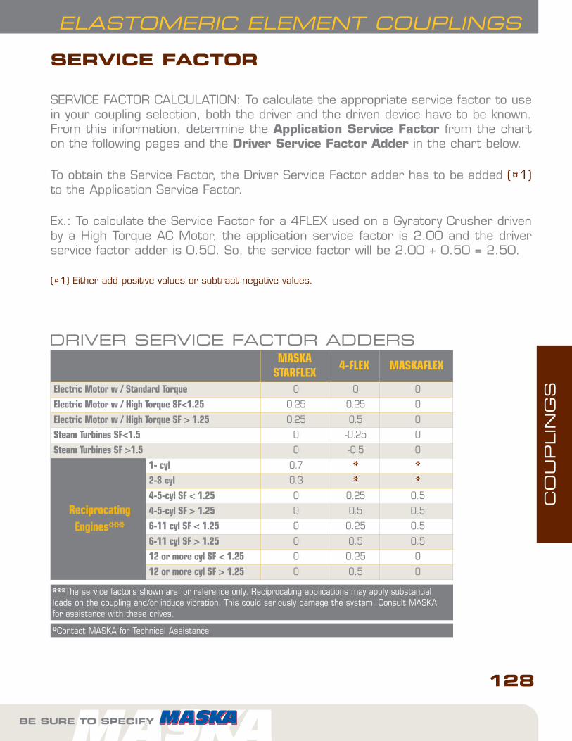
Electric Motor w / Standard Torque 0 0 0
Electric Motor w / High Torque SF<1.25 0.25 0.25 0
Electric Motor w / High Torque SF > 1.25 0.25 0.5 0
Steam Turbines SF<1.5 0 -0.25 0
Steam Turbines SF >1.5 0 -0.5 0
ReciprocatingEngines***
1- cyl 0.7 * *2-3 cyl 0.3 * *4-5-cyl SF < 1.25 0 0.25 0.5
4-5-cyl SF > 1.25 0 0.5 0.5
6-11 cyl SF < 1.25 0 0.25 0.5
6-11 cyl SF > 1.25 0 0.5 0.5
12 or more cyl SF < 1.25 0 0.25 0
12 or more cyl SF > 1.25 0 0.5 0
*Contact MASKA for Technical Assistance
***The service factors shown are for reference only. Reciprocating applications may apply substantialloads on the coupling and/or induce vibration. This could seriously damage the system. Consult MASKAfor assistance with these drives.
SERVICE FACTOR
SERVICE FACTOR CALCULATION: To calculate the appropriate service factor to usein your coupling selection, both the driver and the driven device have to be known.From this information, determine the Application Service Factor from the charton the following pages and the Driver Service Factor Adder in the chart below.
To obtain the Service Factor, the Driver Service Factor adder has to be added (¤1)to the Application Service Factor.
Ex.: To calculate the Service Factor for a 4FLEX used on a Gyratory Crusher drivenby a High Torque AC Motor, the application service factor is 2.00 and the driverservice factor adder is 0.50. So, the service factor will be 2.00 + 0.50 = 2.50.
(¤1) Either add positive values or subtract negative values.
DRIVER SERVICE FACTOR ADDERS

CO
UPLIN
GS
129
ELASTOMERIC ELEMENT COUPLINGS
FOR DEPENDABLE DRIVE COMPONENTS, BE SURE TO SPECIFY
APPLICATION SERVICE FACTORS MASKA STARFLEX 4-FLEX MASKAFLEXAgitators 1.00 1.25 1.00BlowersCentrifugalLobeVane
1.001.251.25
1.251.501.25
1.001.501.00
Brewing & distillingBottling Machinery, Brew Kettles (distilling)Cookers
1.251.25
1.251.25
1.001.00
Car Dumpers 2.50 2.00 1.50Car Pullers 1.50 2.00 1.50Compressors **CentrifugalScrewLobeReciprocating1 cylinder - single acting1 cylinder - double acting2 cylinder- single acting2 cylinder - double acting3 cl, or more - single acting3 cl, or more - double acting
1.001.251.25
******
1.251.251.25
******
1.001.002.00
3.503.003.002.502.502.00
ConveyorsAssembly, Belt, Oven, Screw 1.2 1.25 1.00Cranes & HoistMain Hoist-Medium DutyMain Hoist-Heavy Duty
1.502.00
1.502.00
1.502.00
CrushersCaneGyratory
3.503.00
2.002.00
2.002.50
DredgesCable reelsCutter Head DrivesManeuvering and Utility Winch, Pumps
2.002.501.50
1.502.001.50
1.502.501.50
Dynamometer 1.50 1.25 1.00FansCentrifugalCooling TowersForced Draft Propeller
1.002.001.50
1.252.001.50
1.002.001.50
FeedersBeltScrewReciprocatingFilter, Press-oil
1.001.002.501.50
1.251.502.001.50
----
GeneratorsNot WeldingHoistWelding
1.001.502.00
1.251.502.00
1.001.502.00
Kilns 1.50 2.00 2.00Lumber MachineryBand ResawBarkers, Edger Feeder, LOG HAULPlaner, Slab ConveyorLive Roll - ReciprocatingSawdust Conveyor
1.502.002.002.001.25
1.502.001.50
-1.25
1.502.001.502.001.00
SERVICE FACTOR (continued)

CO
UPLIN
GS
130
ELASTOMERIC ELEMENT COUPLINGS
BE SURE TO SPECIFY
APPLICATION SERVICE FACTORS MASKA STARFLEX 4-FLEX MASKAFLEXMachine ToolsMain DrivePunch Press-gear Driven, Plate Planer
1.502.00
1.501.50
1.501.50
Metal Forming MachinesDraw Bench, Carriage & Main DriveExtruderWire Drawing
2.002.002.00
2.002.002.00
2.002.002.00
Mills, Rotary TypeBall, PebbleTubeRodDryers, CoolersTumbling, Tumbling Barrel, Rubber Tumbling
2.002.002.002.001.50
2.002.002.001.502.00
2.502.502.501.501.50
MixersConcrete, continuousMuller
1.751.50
1.501.50
1.501.50
Oil IndustryChiller (oil)
1.50 1.50 1.00
Paper MillsAgitator (mixers), Reel, WinderBarking DrumBeater, PulperJordansCalendersSuction Roll (paper)Winder
1.202.502.002.001.501.501.20
1.502.001.502.002.001.501.50
1.002.501.502.002.002.001.50
Printing Presses 1.50 1.50 1.50Barge Haul Puller 2.00 2.00 2.50PulverisersHammermill-Light DutyHammermill-Heavy Duty
2.002.00
1.502.00
1.502.00
Pug Mill 1.75 1.50 1.50PumpsCentrifugalGearReciprocating:1–Cyl, Single Acting1–Cyl, Double Acting2–Cyl, Single Acting2–Cyl, Double Acting3 or more Cyl
1.001.25
2.002.002.001.751.50
1.251.50
*****
1.001.50
2.502.002.001.501.50
Rubber MachineryBanbury MixersCalender
2.502.00
2.002.00
2.502.00
ScreensAir washing, WaterCoal and Sand RotaryVibratingGrizzly
1.001.502.502.00
1.251.502.002.00
1.001.502.502.00
Textile MachineryCard MachineMangelLoom, Spinner, Tenter framesTumbling Barrels
1.751.201.501.75
2.001.251.502.00
1.501.001.502.00
Windlass 2.00 1.50 1.50Woodworking Machines 1.00 1.25 1.00
*Contact MASKA for technical assistance** Add 0.5 to factor if without flywheel

CO
UPLIN
GS
MASKA STARFLEX:ELASTOMERIC JAW TYPE COUPLINGS
131
STARFLEX COUPLINGS
FOR DEPENDABLE DRIVE COMPONENTS, BE SURE TO SPECIFY
STOCK BORE COUPLINGEXAMPLE: L099X5/8
L099 X5/8
L099: MASKA STARFLEX HUB SIZE
X5/8: BORE SIZE (5/8")
HOW TO ORDER
Careful selection of the type ofinsert based on the service factorwill result in efficient, long-lastingoperations
IMPORTANT REMINDER
The most commonly used elastomeric coupling for awide variety of light to medium-duty applications.
• Interchangeable by part number and size withcorresponding components
• Cost saving component• 4 types of insert materials for various applica-
tions in varying temperatures and environments
DID YOU KNOW THAT...
ELEMENT MATERIALEXAMPLE: L099-100H
L099-100 H
L099-100: MASKA STARFLEX element size(insert)
H : MATERIAL (HYTREL)
To order a complete coupling, (2) hubs with appro-priate bore and (1) insert have to be ordered.
Product Features
• High torque capability• Easy Installation• Misalignment capability• No metal-to-metal contact

CO
UPLIN
GS
132
STARFLEX COUPLINGS
BE SURE TO SPECIFY
ELEMENT CHARACTERISTICS
PropertiesTemperature
Range
MisalignmentShore
HardnessDampeningCapacity
ChemicalResistance
ColourAngularDegree
ParallelInch
NBR (Rubber) Nitrile Butadiene Rubberis an elastomeric element that is oilresistant with the resilience and elasticity of natural rubber.
Most economical and widely-usedelement.
-40° to +212° F
-40° to +100°C
1° .015 80A HIGH GOOD
BLACK
Urethane -- Urethane has 1.5 moretorque capability than NBR, providesless dampening effect and has good resistance to oil and chemicals.
Not recommended for cyclic or start-stop applications.
-30° to +160° F
-34° to +71° C1° .015
55DL050-L110
90-95AL150-L225
LOW VERY GOOD
ORANGE
Hytrel -- Hytrel is a pliant elastomer suited to high torque / temperatureoperations. Notable resistance to oil andchemincals
Not recommended for cyclic or start-stop applications.
-60° to +250° F
-51° to 121° C1/2° .015 55D LOW EXCELLENT
BEIGE
Bronze -- Bronze is a metal insertdesigned exclusively for slow speed )operations that require high torque.(Maximum 250 RPM)
Resistant to extreme environments (temperature, water, oil, dirt).
-40° to +450° F
-40° to +232°C
1/2° .010 -- NIL EXCELLENT
GOLD
Jaw Couplings AdvantagesJaw design is considered “fail-safe” - if theinsert element wears/breaks away, the coupling continues to operate until insert canbe conveniently replaced.
Simple design means easy installation, removaland visual inspection. Also offers lighter weightand lower cost vs. torque capacity.
Insert ChoiceThe choice of the insert element can make a significant difference in the couplings’s performance with regards to vibration, temperature, chemicals, misalignment, high rpm,space limitations and installation/removal.
Maintenance TipsThrough manual inspection, avoid allowing thejaw tips to come into contact; a noisy, grindingoperation will result. Do not hesitate to replacethe insert if signs of wear are evident.
Do not over-estimate service factors whenchoosing the coupling / insert. This increasescosts unnecessarily and can cause damageelsewhere in the drive. Due to the variety ofinserts available, careful selection will result inefficient, long-lasting operations.
Selecting the proper insert material is just as important asselecting the correct type and size of jaw coupling because of therole they play in the performance and maintenance of the product.
IMPORTANT REMINDER

CO
UPLIN
GS
133
STARFLEX COUPLINGS
HubNo.
ListPrice($)
Insert ElementsNBR (Rubber) Urethane Hytrel Wt.
lbs.
Bronze
Part No.List
PricePart No.
ListPrice
Part No.List
PricePart No.
ListPrice
Wt.lbs.
L035* (4) 13.00 L035N* (4) 8.40 - - - - .01 - - -
L050* (4) 13.00 L050N* (4) 8.40 L050U* (4) 34.00 L050H* (4) 28.40 .01 L050B* (4) 47.60 .06
L070 5.05 L070N 3.00 L070U 5.90 L070H 10.00 .02 L070B 14.50 .07
L075 5.80 L075N 5.10 L075U 7.30 L075H 15.00 .03 L075B 23.20 .10
L090 8.90 L090-095N 6.60 L090-095U 10.50 L090-095H 20.00 .04 L090-095B 25.60 .17
L095 13.70 L090-095N 6.60 L090-095U 10.50 L090-095H 20.00 .04 L090-095B 25.60 .17
L099 17.30 L099-100N 13.90 L099-100U 27.60 L099-100H 47.60 .07 L099-100B 37.80 .33
L100 25.60 L099-100N 13.90 L099-100U 27.60 L099-100H 47.60 .07 L099-100B 37.80 .33
L110 35.00 L110N 16.00 L110U 52.40 L110H 57.60 .14 L110B 45.40 .63
L150 44.80 L150N 23.00 L150U 63.40 L150H 69.20 .21 L150B 146.00 1.01
L190 70.00 L190N 28.00 L190U 68.40 L190H 81.60 .27 L190B 222.00 1.35
L225 85.00 L225N 33.50 L225U 86.60 L225H 95.80 .41 L225B 284.00 2.05
HUB AND ELEMENTS
GENERAL ORDERING INFORMATION
FOR DEPENDABLE DRIVE COMPONENTS, BE SURE TO SPECIFY

CO
UPLIN
GS
STARFLEX COUPLINGS
HubNo.
TypeOutside
DiameterA
HubDiameter
HD
OverallLength
B
Distancebetweenflanges
C
Lengththru bore
D
Bore AssyWt.Lbs.(Avg)
Approx.WR2
lbs-in2Min. Max.
L035 * 1 5/8 - 13/16 9/32 17/64 1/8 (4mm) 3/8 (8mm) 0.10 0.003
L050 * 1 1 1/16 - 1 23/32 15/32 5/8 3/16 (5mm) 5/8 (16mm) 0.25 0.054
L070 1 1 3/8 - 2 1/2 3/4 3/16 (7mm) 3/4 (19mm) 0.50 0.115
L075 1 1 3/4 - 2 1/8 1/2 13/16 3/16 (9mm) 7/8 (22mm) 0.90 0.388
L090 1 2 1/8 - 2 9/64 33/64 13/16 3/16 (8mm) 1 (25mm) 1.35 0.772
L095 1 2 1/8 - 2 33/64 33/64 1 7/16 (11mm) 1 1/8 (28mm) 1.55 0.890
L099 1 2 17/32 - 2 27/32 23/32 1 1/16 7/16 (14mm) 1 3/16 (30mm) 2.25 2.048
L100 1 2 17/32 - 3 15/32 23/32 1 3/8 7/16 (12mm) 1 3/8 (35mm) 2.80 2.783
L110 1 3 5/16 - 4 1/4 7/8 1 11/16 5/8 (16mm) 1 5/8 (42mm) 5.95 8.993
L150 1 3 3/4 - 4 1/2 1 1 3/4 5/8 (16mm) 1 7/8 (48mm) 7.90 11.477
L190 2 4 1/2 4 5 1 2 3/4 (19mm) 2 1/8 (55mm) 13.80 39.256
L225 2 5 4 1/4 5 3/8 1 2 3/16 3/4 (30mm) 2 5/8 (65mm) 17.30 65.000
HubNo.
Set Screws Tighteningtorque in-lbs.Qty.
Size
Inch Series Metric Series
L035 1 #6-32 - 7
L050 2 1/4-20 M4-0.7 45
L070 2 1/4-20 M6-1 78
L075 2 1/4-20 M6-1 78
L090 2 1/4-20 M6-1 78
L095 2 5/16-18 M8-1.25 80
L099 2 5/16-18 M8-1.25 150
L100 2 5/16-18 M8-1.25 150
L110 2 3/8-16 M10-1.5 225
L150 2 3/8-16 M10-1.5 260
L190 2 1/2-13 M12-1.75 540
L225 2 1/2-13 M12-1.75 540
DIMENSIONS
WRENCH TORQUE TO TIGHTEN SCREWS
*Important: NOT SOLD INDIVIDUALLY. These parts are packaged 4 to a box.
BE SURE TO SPECIFY
TYPE 2
TYPE 1
134

CO
UPLIN
GS
Bore(in)
Keyway(in)
L035 L050 L070 L075 L090 L095 L099 L100 L110 L150 L190 L225
1/8 No KW X3/16 No KW X X X X X1/4 No KW X X X X X1/4 1/8 x 1/16 POR5/16 No KW X X X X X3/8 No KW X X X X X3/8 3/32 x 3/64 POR POR POR3/8 1/8 x 1/16 POR POR POR POR POR POR POR7/16 No KW POR X X X X X X7/16 3/32 x 3/64 X X POR POR POR POR POR7/16 1/8 x 1/16 POR POR POR POR POR POR POR1/2 No KW X X X X X X1/2 1/8 x 1/16 X X X X X X X9/16 No KW X POR POR POR POR POR POR9/16 1/8 x 1/16 POR X X X X X X5/8 No KW X X POR POR POR POR POR POR POR5/8 5/32 x 5/64 POR POR X POR POR POR POR POR5/8 3/16 x 3/32 X X X X X X X X X
11/16 3/16 x 3/32 X X X X X X X3/4 No KW POR POR POR POR POR POR POR POR POR POR3/4 1/8 x 1/16 POR POR POR POR POR POR POR POR POR3/4 3/16 x 3/32 X X X X X X X X X
13/16 3/16 x 3/32 X X X X X X X X7/8 No KW POR POR POR POR POR POR POR POR7/8 3/16 x 3/32 X X X X X X X X7/8 1/4 x 1/8 POR POR POR POR POR POR POR
15/16 1/4 x 1/8 X X X X X X X1 1/4 x 1/8 X X X X X X X1 3/16 x 3/32 POR POR POR POR POR POR POR
1 1/16 1/4 x 1/8 X X X X X X X1 1/8 1/4 x 1/8 X X X X X X X1 3/16 1/4 x 1/8 X X X X X X1 1/4 1/4 x 1/8 X X X X X1 1/4 5/16 x 5/32 POR POR POR POR POR1 5/16 5/16 x 5/32 X X X X X1 3/8 5/16 x 5/32 X X X X X1 3/8 3/8 x 3/16 POR POR POR POR POR1 7/16 3/8 x 3/16 X X X X1 1/2 5/16 x 5/32 POR POR POR POR1 1/2 3/8 x 3/16 X X X X1 9/16 3/8 x 3/16 X X X X1 5/8 3/8 x 3/16 X X X X
1 11/16 3/8 x 3/16 X X X1 3/4 3/8 x 3/16 X X X1 3/4 7/16 x 7/32 POR POR POR
1 13/16 1/2 x 1/4 X X X1 7/8 1/2 x 1/4 X X X
1 15/16 1/2 x 1/4 X X2 1/2 x 1/4 X X
2 1/16 1/2 x 1/4 X X2 1/8 1/2 x 1/4 X X2 3/16 1/2 x 1/4 X2 1/4 1/2 x 1/4 X2 3/8 5/8 x 5/16 X2 5/8 5/8 x 5/16 X
INCH SERIES: STANDARD BORES AND KEYWAYS
X = Stock POR = Price on Request
135
STARFLEX COUPLINGS
FOR DEPENDABLE DRIVE COMPONENTS, BE SURE TO SPECIFY

CO
UPLIN
GS
136
STARFLEX COUPLINGS
Bore(in)
Keyway(in)
L035 L050 L070 L075 L090 L095 L099 L100 L110 L150 L190 L225
4 No KW POR5 No KW POR POR6 No KW POR POR7 No KW POR POR POR8 No KW POR POR POR POR9 3 x 1.4 POR POR POR10 No KW POR POR POR10 3 x 1.4 X POR POR POR11 4 x 1.8 X X POR POR12 No KW POR POR POR12 4 x 1.8 X X X POR POR POR14 No KW POR POR POR POR14 5 x 2.3 POR X X POR POR POR POR15 No KW POR POR POR POR POR15 5 x 2.3 POR X X POR POR POR POR16 5 x 2.3 POR X X POR POR POR POR POR POR17 5 x 2.3 POR POR X POR POR POR POR18 6 x 2.8 POR POR POR POR POR POR POR19 No KW POR POR19 6 x 2.8 X X X X POR POR POR POR POR20 6 x 2.8 X X X POR POR POR POR POR22 6 x 2.8 X X X X POR POR POR24 8 x 3.3 X X X X X POR POR25 8 x 3.3 POR X X X X POR POR28 No KW POR POR28 8 x 3.3 X X X X POR POR30 8 x 3.3 POR X X POR POR POR32 No KW POR POR POR32 10 x 3.3 POR X X POR POR35 No KW POR POR POR35 10 x 3.3 POR POR POR POR X38 10 x 3.3 X X POR POR40 12 x 3.3 POR POR POR POR42 12 x 3.3 X X X POR45 14 x 3.8 X POR POR48 No KW POR48 14 x 3.8 POR POR X50 No KW POR POR50 14 x 3.8 POR POR55 No KW POR POR55 16 x 4.3 X X60 No KW POR60 18 x 4.4 POR65 No KW 65 18 x 4.4 POR
METRIC SERIES: STANDARD BORES AND KEYWAYS
X = Stock POR = Price on Request
BE SURE TO SPECIFY
STARFLEX COUPLINGS

CO
UPLIN
GS
137
STARFLEX COUPLINGS
FOR DEPENDABLE DRIVE COMPONENTS, BE SURE TO SPECIFY
COUPLING RATINGS & MISALIGNMENT
Hub Size
ElementMaterial
MaxRPM
HP per 100 RPMService Factor Torque
(in. lbs.)
Max. parallel
misalignment(in.)
Max. angular
misalignment(in.)1.0 1.5 2.0 2.5 3.0
L035 NBR 31000 0.006 0.004 0.003 0.002 0.002 3.5 0.015 0.010
L050 18000 0.042 0.028 0.021 0.017 0.014 26.3 0.015 0.018
L070 14000 0.069 0.046 0.035 0.028 0.023 43.2 0.015 0.022
L075 11000 0.143 0.095 0.072 0.057 0.048 90 0.015 0.030
L090 9000 0.228 0.152 0.114 0.091 0.076 144 0.015 0.035
L095 9000 0.308 0.205 0.154 0.123 0.103 194 0.015 0.035
L099 7000 0.505 0.337 0.253 0.202 0.168 318 0.015 0.040
L100 7000 0.662 0.441 0.331 0.265 0.221 417 0.015 0.040
L110 5000 1.257 0.838 0.629 0.503 0.419 792 0.015 0.055
L150 5000 1.967 1.311 0.984 0.787 0.656 1240 0.015 0.065
L190 5000 2.742 1.828 1.371 1.097 0.914 1728 0.015 0.075
L225 4200 3.713 2.475 1.857 1.485 1.238 2340 0.015 0.085
NBR - (NITRILE BUTADIENE RUBBER) ELEMENT MATERIAL
Hub Size
ElementMaterial
MaxRPM
HP per 100 RPMService Factor Torque
(in. lbs.)
Max. parallel
misalignment(in.)
Max. angular
misalignment(in.)1.0 1.5 2.0 2.5 3.0
L035 Urethane 31000 - - - - - - - -
L050 18000 0.062 0.041 0.031 0.025 0.021 39 0.015 0.018
L070 14000 0.103 0.069 0.052 0.041 0.034 65 0.015 0.022
L075 11000 0.214 0.143 0.107 0.086 0.071 135 0.015 0.030
L090 9000 0.343 0.229 0.172 0.137 0.114 216 0.015 0.035
L095 9000 0.462 0.308 0.231 0.185 0.154 291 0.015 0.035
L099 7000 0.757 0.505 0.379 0.303 0.252 477 0.015 0.040
L100 7000 0.993 0.662 0.497 0.397 0.331 626 0.015 0.040
L110 5000 1.885 1.257 0.943 0.754 0.628 1188 0.015 0.055
L150 5000 2.951 1.967 1.476 1.180 0.984 1860 0.015 0.065
L190 5000 4.113 2.742 2.057 1.645 1.371 2592 0.015 0.075
L225 4200 5.569 3.713 2.785 2.228 1.856 3510 0.015 0.085
URETHANE - ELEMENT MATERIAL
NOTE: Angular misalignment is the difference between X and X max. Refer to Figure 2 on the followingpage.

CO
UPLIN
GS
138
STARFLEX COUPLINGS
BE SURE TO SPECIFY
HubSize
ElementMaterial
MaxRPM
HP per 100 RPMService Factor Torque
(in. lbs.)
Max. parallel
misalignment(in.)
Max. angular
misalignment(in.)1.0 1.5 2.0 2.5 3.0
L035 Hytrel 31000 - - - - - - - -L050 18000 0.079 0.053 0.040 0.032 0.026 50 0.015 0.012L070 14000 0.181 0.121 0.091 0.072 0.060 114 0.015 0.012L075 11000 0.360 0.240 0.180 0.144 0.120 227 0.015 0.015L090 9000 0.636 0.424 0.318 0.254 0.212 401 0.015 0.018L095 9000 0.890 0.593 0.445 0.356 0.297 561 0.015 0.018L099 7000 1.257 0.838 0.629 0.503 0.419 792 0.015 0.022L100 7000 1.799 1.199 0.900 0.720 0.600 1134 0.015 0.022L110 5000 3.599 2.399 1.800 1.440 1.200 2268 0.015 0.030L150 5000 5.883 3.922 2.942 2.353 1.961 3708 0.015 0.033L190 5000 7.426 4.951 3.713 2.970 2.475 4680 0.015 0.040L225 4200 9.882 6.588 4.941 3.953 3.294 6228 0.015 0.044
HYTREL - ELEMENT MATERIAL
Hub Size
ElementMaterial
MaxRPM
HP per 100 RPMService Factor Torque
(in. lbs.)
Max. parallel
misalignment(in.)
Max. angular
misalignment(in.)1.0 1.5 2.0 2.5 3.0
L035 Bronze 250 - - - - - - - -L050 250 0.079 0.053 0.040 0.032 0.026 50 0.01 0.012L070 250 0.181 0.121 0.091 0.072 0.060 114 0.01 0.012L075 250 0.360 0.240 0.180 0.144 0.120 227 0.01 0.015L090 250 0.636 0.424 0.318 0.254 0.212 401 0.01 0.018L095 250 0.890 0.593 0.445 0.356 0.297 561 0.01 0.018L099 250 1.257 0.838 0.629 0.503 0.419 792 0.01 0.022L100 250 1.799 1.199 0.900 0.720 0.600 1134 0.01 0.022L110 250 3.599 2.399 1.800 1.440 1.200 2268 0.01 0.030L150 250 5.883 3.922 2.942 2.353 1.961 3708 0.01 0.033L190 250 7.426 4.951 3.713 2.970 2.475 4680 0.01 0.040L225 250 9.882 6.588 4.941 3.953 3.294 6228 0.01 0.044
BRONZE - ELEMENT MATERIAL
Parallel MisalignmentFigure 1
Angular MisalignmentFigure 2
NOTE: Angular misalignment is the difference between X and X max. Refer to Figure 2 on thefollowing page.

CO
UPLIN
GS
139
STARFLEX COUPLINGS
FOR DEPENDABLE DRIVE COMPONENTS, BE SURE TO SPECIFY
860 RPM MOTORS 1160 RPM MOTORS
HP Service Factors HP Service Factors1.0 1.25 1.5 2.0 2.5 1.0 1.25 1.5 2.0 2.5
1/8 L050 L050 L050 L050 L050 1/8 L050 L050 L050 L050 L050
1/4 L050 L050 L070 L070 L075 1/4 L050 L050 L050 L070 L070
1/3 L050 L070 L070 L075 L075 1/3 L050 L050 L070 L070 L075
1/2 L070 L075 L075 L075 L090 1/2 L070 L070 L070 L075 L075
3/4 L075 L075 L075 L090 L090 3/4 L070 L075 L075 L075 L090
1 L075 L090 L090 L095 L095 1 L075 L075 L075 L090 L090
1 1/2 L090 L090 L095 L099 L099 1 1/2 L075 L090 L090 L095 L099
2 L095 L095 L099 L099 L100 2 L090 L090 L095 L099 L099
3 L099 L099 L100 L110 L110 3 L095 L099 L099 L100 L100
5 L100 L110 L110 L110 L150 5 L099 L100 L100 L110 L110
7 1/2 L110 L110 L150 L150 L190 7 1/2 L100 L110 L110 L150 L150
10 L110 L150 L150 L190 L225 10 L110 L110 L150 L150 L190
15 L150 L190 L190 L225 - 15 L150 L150 L150 L190 L225
20 L190 L225 L225 - - 20 L150 L190 L190 L225 -
25 L225 L225 - - - 25 L190 L190 L225 - -
30 L225 - - - - 30 L190 L225 - - -
40 - - - - - 40 L225 - - - -
50 - - - - - 50 - - - - -
60 - - - - - 60 - - - - -
75 - - - - - 75 - - - - -
NBR - (NITRILE BUTADIENE RUBBER) ELEMENT MATERIAL
COUPLING SELECTION - SERVICE FACTORS FOR ELEMENT MATERIALS

CO
UPLIN
GS
140
STARFLEX COUPLINGS
BE SURE TO SPECIFY
1750 RPM MOTORS 3500 RPM MOTORS
HP Service Factors HP Service Factors1.0 1.25 1.5 2.0 2.5 1.0 1.25 1.5 2.0 2.5
1/8 L050 L050 L050 L050 L050 1/8 L035 L035 L035 L050 L050
1/4 L050 L050 L050 L050 L050 1/4 L050 L050 L050 L050 L050
1/3 L050 L050 L050 L050 L070 1/3 L050 L050 L050 L050 L050
1/2 L050 L050 L070 L070 L075 1/2 L050 L050 L050 L050 L050
3/4 L070 L070 L070 L075 L075 3/4 L050 L050 L050 L070 L070
1 L070 L075 L075 L075 L075 1 L050 L050 L070 L070 L075
1 1/2 L075 L075 L075 L090 L090 1 1/2 L070 L070 L070 L075 L075
2 L075 L075 L090 L090 L095 2 L070 L075 L075 L075 L075
3 L090 L090 L095 L099 L099 3 L075 L075 L075 L090 L090
5 L095 L099 L099 L100 L110 5 L075 L090 L090 L095 L099
7 1/2 L099 L100 L100 L110 L110 7 1/2 L090 L095 L099 L099 L100
10 L100 L110 L110 L110 L150 10 L095 L099 L099 L100 L110
15 L110 L110 L150 L150 L190 15 L099 L100 L100 L110 L110
20 L110 L150 L150 L190 L225 20 L100 L110 L110 L110 L150
25 L150 L150 L190 L225 L225 25 L110 L110 L110 L150 L150
30 L150 L190 L190 L225 - 30 L110 L110 L150 L150 L190
40 L190 L225 L225 - - 40 L110 L150 L150 L190 L225
50 L225 L225 - - - 50 L150 L150 L190 L225 L225
60 L225 - - - - 60 L150 L190 L190 L225 -
75 - - - - - 75 L190 L190 L225 - -
NBR - MASKA STARFLEX

CO
UPLIN
GS
141
STARFLEX COUPLINGS
FOR DEPENDABLE DRIVE COMPONENTS, BE SURE TO SPECIFY
860 RPM MOTORS 1160 RPM MOTORS
HP Service Factors HP Service Factors1.0 1.25 1.5 2.0 2.5 1.0 1.25 1.5 2.0 2.5
1/8 L050 L050 L050 L050 L050 1/8 L050 L050 L050 L050 L050
1/4 L050 L050 L050 L050 L070 1/4 L050 L050 L050 L050 L050
1/3 L050 L050 L050 L070 L070 1/3 L050 L050 L050 L050 L070
1/2 L050 L070 L070 L075 L075 1/2 L050 L050 L070 L070 L075
3/4 L070 L075 L075 L075 L090 3/4 L070 L070 L070 L075 L075
1 L075 L075 L075 L090 L090 1 L070 L075 L075 L075 L075
1 1/2 L075 L090 L090 L095 L095 1 1/2 L075 L075 L075 L090 L090
2 L090 L090 L095 L095 L099 2 L075 L075 L090 L090 L095
3 L095 L095 L099 L099 L100 3 L090 L090 L095 L099 L099
5 L099 L099 L100 L110 L110 5 L095 L099 L099 L100 L110
7 1/2 L100 L110 L110 L110 L150 7 1/2 L099 L100 L100 L110 L110
10 L110 L110 L110 L150 L150 10 L100 L110 L110 L110 L150
15 L110 L150 L150 L190 L225 15 L110 L110 L150 L150 L190
20 L150 L150 L190 L225 - 20 L110 L150 L150 L190 L225
25 L150 L190 L225 - - 25 L150 L150 L190 L225 L225
30 L190 L225 L225 - - 30 L150 L190 L190 L225 -
40 L225 - - - - 40 L190 L225 L225 - -
50 - - - - - 50 L225 L225 - - -
60 - - - - - 60 L225 - - - -
75 - - - - - 75 - - - - -
100 - - - - - 100 - - - - -
125 - - - - - 125 - - - - -
150 - - - - - 150 - - - - -
URETHANE - ELEMENT MATERIAL
COUPLING SELECTION - SERVICEFACTORS FOR ELEMENT MATERIALSCONTINUED

CO
UPLIN
GS
142
STARFLEX COUPLINGS
BE SURE TO SPECIFY
1750 RPM MOTORS 3500 RPM MOTORS
HP Service Factors HP Service Factors1.0 1.25 1.5 2.0 2.5 1.0 1.25 1.5 2.0 2.5
1/8 L050 L050 L050 L050 L050 1/8 L050 L050 L050 L050 L050
1/4 L050 L050 L050 L050 L050 1/4 L050 L050 L050 L050 L050
1/3 L050 L050 L050 L050 L050 1/3 L050 L050 L050 L050 L050
1/2 L050 L050 L050 L050 L070 1/2 L050 L050 L050 L050 L050
3/4 L050 L050 L070 L070 L075 3/4 L050 L050 L050 L050 L050
1 L050 L070 L070 L075 L075 1 L050 L050 L050 L050 L070
1 1/2 L070 L075 L075 L075 L075 1 1/2 L050 L050 L070 L070 L075
2 L075 L075 L075 L090 L090 2 L050 L070 L070 L075 L075
3 L075 L075 L090 L090 L095 3 L070 L075 L075 L075 L075
5 L090 L095 L095 L099 L099 5 L075 L075 L075 L090 L095
7 1/2 L095 L099 L099 L100 L110 7 1/2 L075 L090 L090 L095 L099
10 L099 L099 L100 L110 L110 10 L090 L095 L095 L099 L099
15 L100 L110 L110 L110 L150 15 L095 L099 L099 L100 L110
20 L110 L110 L110 L150 L150 20 L099 L099 L100 L110 L110
25 L110 L110 L150 L150 L190 25 L099 L100 L110 L110 L110
30 L110 L150 L150 L190 L225 30 L100 L110 L110 L110 L150
40 L150 L150 L190 L225 - 40 L110 L110 L110 L150 L150
50 L150 L190 L225 - 50 L110 L110 L150 L150 L190
60 L190 L225 L225 - - 60 L110 L150 L150 L190 L225
75 L225 L225 - - - 75 L150 L150 L190 L225 L225
100 - - - 100 L150 L190 L225 - -
125 - - - 125 L190 L225 L225 - -
150 - - - 150 L225 L225 - - -
URETHANE - MASKA STARFLEX

CO
UPLIN
GS
143
STARFLEX COUPLINGS
FOR DEPENDABLE DRIVE COMPONENTS, BE SURE TO SPECIFY
860 RPM MOTORS 1160 RPM MOTORS
HP Service Factors HP Service Factors1.0 1.25 1.5 2.0 2.5 1.0 1.25 1.5 2.0 2.5
1/8 L050 L050 L050 L050 L050 1/8 L050 L050 L050 L050 L050
1/4 L050 L050 L050 L050 L050 1/4 L050 L050 L050 L050 L050
1/3 L050 L050 L050 L050 L070 1/3 L050 L050 L050 L050 L050
1/2 L050 L050 L070 L070 L070 1/2 L050 L050 L050 L070 L070
3/4 L070 L070 L070 L070 L075 3/4 L050 L070 L070 L070 L070
1 L070 L070 L070 L075 L075 1 L070 L070 L070 L070 L075
1 1/2 L070 L075 L075 L075 L090 1 1/2 L070 L070 L075 L075 L075
2 L075 L075 L075 L090 L090 2 L070 L075 L075 L075 L090
3 L075 L090 L090 L095 L095 3 L075 L075 L090 L090 L095
5 L090 L095 L095 L099 L100 5 L090 L090 L095 L095 L099
7 1/2 L095 L099 L100 L100 L110 7 1/2 L095 L095 L099 L100 L100
10 L099 L100 L100 L110 L110 10 L095 L099 L100 L100 L110
15 L100 L110 L110 L110 L150 15 L100 L100 L110 L110 L110
20 L110 L110 L110 L150 L150 20 L100 L110 L110 L110 L150
25 L110 L110 L150 L150 L190 25 L110 L110 L110 L150 L150
30 L110 L150 L150 L190 L225 30 L110 L110 L150 L150 L190
40 L150 L150 L190 L225 - 40 L110 L150 L150 L190 L225
50 L150 L190 L225 - - 50 L150 L150 L190 L225 -
60 L190 L225 - - - 60 L150 L190 L225 - -
75 L225 - - - - 75 L190 L225 L225 - -
100 - - - - - 100 L225 - - - -
125 - - - - - 125 - - - - -
150 - - - - - 150 - - - - -
200 - - - - - 200 - - - - -
250 - - - - - 250 - - - - -
300 - - - - - 300 - - - - -
HYTREL - ELEMENT MATERIAL
COUPLING SELECTION - SERVICEFACTORS FOR ELEMENT MATERIALSCONTINUED

CO
UPLIN
GS
144
STARFLEX COUPLINGS
BE SURE TO SPECIFY
1750 RPM MOTORS 3500 RPM MOTORS
HP Service Factors HP Service Factors1.0 1.25 1.5 2.0 2.5 1.0 1.25 1.5 2.0 2.5
1/8 L050 L050 L050 L050 L050 1/8 L050 L050 L050 L050 L050
1/4 L050 L050 L050 L050 L050 1/4 L050 L050 L050 L050 L050
1/3 L050 L050 L050 L050 L050 1/3 L050 L050 L050 L050 L050
1/2 L050 L050 L050 L050 L050 1/2 L050 L050 L050 L050 L050
3/4 L050 L050 L050 L070 L070 3/4 L050 L050 L050 L050 L050
1 L050 L050 L070 L070 L070 1 L050 L050 L050 L050 L050
1 1/2 L070 L070 L070 L070 L075 1 1/2 L050 L050 L050 L070 L070
2 L070 L070 L070 L075 L075 2 L050 L050 L070 L070 L070
3 L070 L075 L075 L075 L090 3 L070 L070 L070 L070 L075
5 L075 L075 L090 L090 L095 5 L070 L070 L075 L075 L075
7 1/2 L090 L090 L095 L095 L099 7 1/2 L075 L075 L075 L090 L090
10 L090 L095 L095 L099 L100 10 L075 L075 L090 L090 L095
15 L095 L099 L100 L100 L110 15 L090 L090 L095 L095 L099
20 L099 L100 L100 L110 L110 20 L090 L095 L095 L099 L100
25 L100 L100 L110 L110 L110 25 L095 L095 L099 L100 L100
30 L100 L110 L110 L110 L150 30 L095 L099 L100 L100 L110
40 L110 L110 L110 L150 L150 40 L099 L100 L100 L110 L110
50 L110 L110 L150 L150 L190 50 L100 L100 L110 L110 L110
60 L110 L150 L150 L190 L225 60 L100 L110 L110 L110 L150
75 L150 L150 L190 L225 - 75 L110 L110 L110 L150 L150
100 L150 L190 L225 - - 100 L110 L110 L150 L150 L190
125 L190 L225 - - - 125 L110 L150 L150 L190 L225
150 L225 - - - - 150 L150 L150 L190 L225 -
200 - - - - - 200 L150 L190 L225 - -
250 - - - - - 250 L190 L225 - - -
300 - - - - - 300 L225 - - - -
HYTREL - ELEMENT MATERIAL

CO
UPLIN
GS
145
4-FLEX COUPLINGS
FOR DEPENDABLE DRIVE COMPONENTS, BE SURE TO SPECIFY
4-FLEX: ELASTOMERIC GEAR TYPE COUPLINGS
• 4-way flexing action
• All types & sizes in cast iron• Precise concentrical product to avoid run-out
and unbalance• No lubrication; smooth, quiet power
transmission• Fast & easy installation; no special tools or
accessories required
DID YOU KNOW THAT...
FLANGEEXAMPLE: 9SX1-9/16
EXAMPLE: 8B-SH
9 X1-1/16
9: 4FLEX FLANGE SIZE
S: 4FLEX FLANGE TYPE
X1-1/16: BORE SIZE (1 1/16")
8: 4FLEX FLANGE SIZE
B: 4FLEX FLANGE TYPE
SH: QD HUB SIZE
HOW TO ORDER
S
8 SHB
ELEMENT MATERIALEXAMPLE: 9JES
9 JES
9: 4FLEX ELEMENT SIZE
JES: ELEMENT MATERIAL AND CONSTRUCTION(EPDM SPLIT - "S" STANDS FOR SPLIT)
NOTE: INSTRUCTIONS ON HOW TO INSTALL INCLUDED WITH EACH FLANGE.

CO
UPLIN
GS
146
4-FLEX COUPLINGS
BE SURE TO SPECIFY
Technical Features• Tight bore tolerance (+.0005 / +.0015)• Over 1000 HP @ 1750 rpm• J & S flanges are bored to size• B flanges are mounted with a QD bushing
TYPES J & S 4-FLEX COUPLING FLANGES• Available in different bore sizes to fit on standard
shafts• Most flanges have a keyseat and all are supplied with
2 setscrews
TYPE B 4-FLEX COUPLING FLANGES• Fits with our QD bushing for easy installation & removal• Secure mounting without setscrews
General Characteristics:• Sizes available 3-10• Sizes in progress 11-13• Torque (in./lbs.) 60 - 47,268• Torsional wind-up 7° - 15°• Parallel misalignment (in.) 0.010 - 0.040• Sleeve Elements: 1-piece, 2-piece & split format
EPDM & Hytrel

CO
UPLIN
GS
FOR DEPENDABLE DRIVE COMPONENTS, BE SURE TO SPECIFY
147
4-FLEX COUPLINGS
DIMENSIONS
FOR DEPENDABLE DRIVE COMPONENTS, BE SURE TO SPECIFY
TYPE “J” COUPLING FLANGE
NOTE: Not to be used with hytrel sleeves.IMPORTANT REMINDER
FlangeSize
ListPrice
$
Dimensions (inches) *Wt.(lbs.)C D E G H L T X
3J 7.50 51/64 2.062 13/32 3/8 1 1/2 1 31/32 25/64 5/8 0.3
4J 9.50 55/64 2.460 27/64 5/8 1 5/8 2 11/32 7/16 5/8 0.4
5J 15.00 1 3/64 3.250 29/64 3/4 1 7/8 2 27/32 19/32 59/64 0.9
6J 21.00 1 5/16 4.000 9/16 7/8 2 1/2 3 1/2 3/4 1 3/32 1.2
* Approximate weight for each flange
Flange Size Stock Bore(inches) Keyseat
3J 3/8 - 1/25/8 - 3/4 - (7/8)
none3/16 x 3/32
4J1/25/8 - 3/4 - 7/815/16 - 1
none3/16 x 3/321/4 x 1/8
5J1/25/8 - 3/4 - 7/815/16 - 1 - 1 1/8
none3/16 x 3/321/4 x 1/8
6J5/8 - 3/4 - 7/815/16 - 1 - 1 1/8 - 1 3/16 - 1 1/41 3/8
3/16 x 3/321/4 x 1/85/16 x 5/32
STOCK BORES
( ) = Price and availability on requestAll finished bores come with 2 setscrews
CO
UPLIN
GS
BE SURE TO SPECIFY
148
4-FLEX COUPLINGS
BE SURE TO SPECIFY
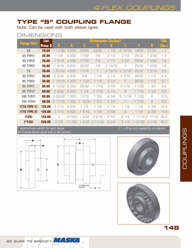
TYPE “S” COUPLING FLANGE
Flange SizeList
Price $Dimensions (inches) *Wt.
(lbs.)C D E G H L T X5S 20.00 1 11/32 3.250 29/64 23/32 1 7/8 2 13/16 19/32 31/32 1.1
6S TYPE16S TYPE26S TYPE3
26.00 1 5/8 4.000 17/32 7/8 2 1/2 3 1/2 25/32 1 3/32 1.9
26.00 1 5/16 4.000 17/32 7/8 2 1/2 3 1/2 25/32 1 3/32 1.8
26.00 1 9/16 4.000 25/32 7/8 2 13/16 4 25/32 1 3/32 1.8
7S 30.00 1 27/32 4.625 11/16 1 2 13/16 3 15/16 25/32 1 5/16 2.6
8S TYPE18S TYPE2
40.00 2 3/32 5.450 3/4 1 1/8 3 1/4 4 7/16 29/32 1 1/2 4.4
40.00 1 15/16 5.450 1 1/32 1 1/8 3 1/4 5 29/32 1 1/2 3.7
9S TYPE19S TYPE2
60.00 2 13/32 6.350 25/32 1 7/16 3 7/8 5 1/16 1 1/32 1 3/4 6.8
60.00 2 9/32 6.350 1 1/4 1 7/16 4 1/8 6 1 1/32 1 3/4 6.2
10S TYPE110S TYPE2
80.00 2 23/32 7.500 13/16 1 5/8 4 3/8 5 11/16 1 7/32 2 10.5
80.00 2 11/16 7.500 1 15/32 1 5/8 4 3/4 7 1 7/32 2 9.8
(11S TYPE 1)(11S TYPE 2)
128.00 3 7/16 8.625 1 1/8 1 7/8 5 1/4 7 1/8 1 1/2 2 3/8 16.6
128.00 3 1/16 8.625 1 9/16 1 7/8 5 5/8 8 1 1/2 2 3/8 16.4
(12S) 156.00 4 10.000 1 9/32 2 5/16 5 3/4 8 1/4 1 11/16 2 11/16 26.6
(*13S) 220.00 4 3/8 11.750 1 5/16 2 11/16 6 3/4 9 1/4 1 31/32 3 1/16 45.2
DIMENSIONS
* Approximate weight for each flange ( ) = Price and availability on requestAll finished bores come with 2 set screws.
Note: Can be used with both sleeve types.

CO
UPLIN
GS
FOR DEPENDABLE DRIVE COMPONENTS, BE SURE TO SPECIFY
4-FLEX COUPLINGS
TYPE “S” COUPLING FLANGE
FOR DEPENDABLE DRIVE COMPONENTS, BE SURE TO SPECIFY
149
FlangeSize
Stock Bore(inches) Keyseat
5S
1/25/8 - 3/4 - 13/16 - 7/815/16 - 1 - 1 1/16 - 1 1/81 3/161 1/4
none3/16 x 3/321/4 x 1/81/4 x 1/81/4 x 1/16**
6S Type 1
5/8 - 3/4 - 7/8 15/16 - 1 - 1 1/16 - 1 1/81 3/16 - 1 1/41 5/16 - 1 3/8 1 7/16 1 1/2
3/16 x 3/321/4 x 1/81/4 x 1/85/16 x 5/323/8 x 3/163/8 x 1/8**
6S Type 2
1 5/81 3/4
3/8 x 1/8**3/8 x 1/16**
6S Type 3 1 7/8 1/2 x 1/16**
7S
5/8 - 3/4 - 7/8 15/16 - 1 - 1 1/16 - 1 1/81 3/16 - 1 1/41 5/16 - 1 3/8 1 7/16 -1 1/2 - 1 5/81 7/8
3/16 x 3/321/4 x 1/81/4 x 1/85/16 x 5/323/8 x 3/161/2 x 1/8**
8S Type1
3/4 - 7/815/16 - 1 - 1 1/8 - 1 3/161 1/41 5/16 - 1 3/81 7/16 - 1 1/2 - 1 9/16 - 1 5/81 11/16 - 1 3/41 7/8 - 1 15/162 1/8
3/16 x 3/321/4 x 1/81/4 x 1/85/16 x 5/323/8 x 3/163/8 x 3/161/2 x 1/41/2 x 3/16**
8S Type 2 2 3/8 5/8 x 1/8**
9S Type 1
7/81 - 1 1/8 - 1 1/41 3/81 7/16 - 1 1/2 - 1 9/16 - 1 5/81 11/16-1 3/4 1 7/8 - 1 15/16 - 2 - 2 1/82 3/16 - 2 1/42 3/8 - 2 1/2
3/16 x 3/321/4 x 1/85/16 x 5/323/8 x 3/163/8 x 3/161/2 x 1/41/2 x 1/45/8 x 5/16
STOCK BORESFlangeSize
Stock Bore(inches) Keyseat
9S Type2 2 7/8 3/4 x 1/8**
10SType 1
1 1/8 - 1 1/41 3/81 7/16 - 1 1/2 - 1 9/16 - 1 5/81 11/16 - 1 3/41 7/8 - 1 15/16 - 2 - 2 1/82 3/16 - 2 1/42 3/8 - 2 7/16 - 2 1/2 - 2 5/82 3/42 7/8
1/4 x 1/85/16 x 5/323/8 x 3/163/8 x 3/161/2 x 1/41/2 x 1/45/8 x 5/165/8 x 5/163/4 x 1/4**
*10SType 2 3 3/8 7/8 x 3/16**
*11SType 1
1 1/41 3/81 1/2 - 1 5/8 - 1 3/41 7/8 - 2 - 2 1/8 - 2 1/4 2 3/8 - 2 3/4 2 7/83 3/83 7/16
none5/16 x 5/323/8 x 3/161/2 x 1/45/8 x 5/163/4 x 3/87/8 x 7/167/8 x 3/16**
*11SType 2 3 7/8 1 x 1/4**
*12S
1 1/21 5/8 - 1 3/41 7/8 - 2 1/8 2 3/8 - 2 3/4 2 7/83 3/8 - 3 7/163 7/8
none3/8 x 3/161/2 x 1/45/8 x 5/163/4 x 3/87/8 x 7/161 x 1/2
*13S
22 1/82 3/82 7/83 3/8 - 3 7/163 15/16
none1/2 x 1/45/8 x 5/163/4 x 3/87/8 x 7/161 x 1/2
The Maska 4-Flex are available from stock in all bores and keyseats listed below. In somecases, as the bore increases in diameter, a shallow keyseat is provided - due to insufficient material thickness. When this happens, Maska furnishes the correct rectan-gular key at no charge. This does not affect the coupling's ability to transmit the load.The rectangular key, or flat key as some call it, fits into the standard keyway in the shaft.
* = Price and availability on request** Shallow keyseatAll finished bores come with 2 set screws

CO
UPLIN
GS
BE SURE TO SPECIFY
150
4-FLEX COUPLINGS
BE SURE TO SPECIFY
TYPE “B” COUPLING FLANGE
NOTE: Not to be used with hytrelsleeves.
IMPORTANT REMINDER
DIMENSIONSFlangeSize
ListPrice $
Bush.Size
Dimensions (inches) Max.Bore
(inches)
*Wt. (lbs.)
C1 C2 D E F G L T X Flange Bush.
6B 38.00 JA 1 17/64 1 4.000 33/64 2 7/8 3 13/32 3/4 1 3/32 1 1/4 1.4 0.4
7B 44.00 JA 1 19/64 1 4.625 33/64 2 1 3 19/32 25/32 1 5/16 1 1/4 1.9 0.4
8B 50.00 SH 1 31/32 1 1/4 5.450 5/8 2 11/16 1 1/8 4 3/16 29/32 1 1/2 1 5/8 2.9 0.9
9B 62.00 SD 2 5/16 1 13/16 6.350 11/16 3 3/16 1 7/16 4 7/8 1 1/32 1 3/4 1 15/16 4.8 1.6
10B 84.00 SK 2 1/32 1 7/8 7.500 13/16 3 7/8 1 5/8 5 11/16 1 7/32 2 2 1/2 7.8 2.7
(11B) 120.00 SF 2 5/16 2 8.625 13/16 4 5/8 1 7/8 6 1/2 1 1/2 2 3/8 2 15/16 12.0 3.9
(12B) 146.00 E 2 29/32 2 5/8 10.000 1 1/8 6 2 5/16 7 15/16 1 11/16 2 11/16 3 1/2 18.0 8.5
(13B) 208.00 F 3 29/32 3 5/8 11.750 1 7/32 6 5/8 2 11/16 9 1/16 1 31/32 3 3 15/16 31.2 13.3
¬ Maximum bore with keyseat * Approximate weight for each flange( ) = Price on request

CO
UPLIN
GS
FOR DEPENDABLE DRIVE COMPONENTS, BE SURE TO SPECIFY
151
4-FLEX COUPLINGS
ELEMENT CHARACTERISTICS
FOR DEPENDABLE DRIVE COMPONENTS, BE SURE TO SPECIFY
JE HS H
JES E E (exploded)
SHAPES AVAILABLE EPDM HYTREL
1 pc, unsplit JE H
1 pc, split JES -
2 pieces E HS
TYPICAL USE General Purpose General Purpose
REL. RATING 1X 4X
WIND-UP ANGULAR 15° 7°
MISALIGNMENT 1° 1/4°
TEMPERATURE
maximum +275° F. +250° F.
minimum –30° F. –65° F.
SLEEVE TYPES

CO
UPLIN
GS
BE SURE TO SPECIFY
152
4-FLEX COUPLINGS
BE SURE TO SPECIFY
Part #List
Price $Part #
List Price $
CouplingSize
D(inches)
W(inches)
Wt.(lbs)
3JE 4.20 3JES 5.60 3 1 7/8 1 0.064JE 6.00 4JES 8.00 4 2 5/16 1 1/4 0.105JE 12.00 5JES 14.00 5 2 15/16 1 9/16 0.206JE 20.00 6JES 22.00 6 3 3/4 1 7/8 0.407JE 26.00 7JES 28.00 7 4 11/32 2 3/16 0.628JE 34.00 8JES 38.00 8 5 1/16 2 1/2 1.139JE 40.00 9JES 44.00 9 6 3 1.4610JE 56.00 10JES 60.00 10 7 1/16 3 7/16 2.32(11E) 164.00 --- 11 8 3/16 4 5.10(12E) 240.00 --- 12 9 9/16 4 11/16 8.10(13E) 420.00 --- 13 11 3/16 5 1/2 13.00
DIMENSIONS
( ) = Price on request
“B” FLANGES “J”, “S” FLANGES
JE & JES
1. SLEEVE2. FLANGE3. BUSHING
EPDM ELEMENT - TYPES “JE”, “JES”, “E”
E
FlangeSize
EPDMElement
Max.RPM
HP PER 100 RPM
Torque(in. lbs.)
Stiffness(in.
lbs./rad)
E (inches)
Allow.Misalignment
(inches)Service Factor
1.0 1.5 2.0 2.5 3.0 Parallel Angular3 JE, JES 9200 0.1 0.07 0.05 0.04 0.03 60 229 1.188 0.010 0.0354 JE, JES 7600 0.2 0.13 0.10 0.08 0.07 120 458 1.500 0.010 0.0435 JE, JES 7600 0.4 0.27 0.20 0.16 0.13 240 916 1.938 0.015 0.0566 JE, JES 6000 0.7 0.47 0.35 0.28 0.23 450 1718 2.375 0.015 0.0707 JE, JES 5250 1.2 0.80 0.60 0.48 0.40 725 2769 2.563 0.020 0.0818 JE, JES 4500 1.8 1.20 0.90 0.72 0.60 1135 4335 2.938 0.020 0.0949 JE, JES 3750 2.9 1.93 1.45 1.16 0.97 1800 6875 3.500 0.025 0.10910 JE, JES 3600 4.6 3.07 2.30 1.84 1.53 2875 10980 4.063 0.025 0.128
(11) E 3600 7.2 4.80 3.60 2.88 2.40 4530 17300 4.875 0.032 0.151(12) E 2800 11.4 7.60 5.70 4.56 3.80 7200 27500 5.688 0.032 0.175(13) E 2400 18.0 12.00 9.00 7.20 6.00 11350 43350 6.625 0.040 0.195
COUPLING RATINGS & MISALIGNMENT
( ) = Price on request

CO
UPLIN
GS
FOR DEPENDABLE DRIVE COMPONENTS, BE SURE TO SPECIFY
153
4-FLEX COUPLINGS
HYTREL ELEMENT - TYPES “H”, “HS”
Part #List
Price $Part #
List Price $
CouplingSize
D(inches)
W(Inches
Wt. (lbs)
6H 80.00 6HS 84.00 6 3 3/4 1 7/8 0.44
7H 116.00 7HS 120.00 7 4 11/32 2 3/16 0.69
8H 126.00 8HS 130.00 8 5 1/16 2 1/2 1.40
9H 166.00 9HS 172.00 9 6 3 1.80
10H 224.00 10HS 230.00 10 7 1/16 3 7/16 2.90
(11H) 346.00 (11HS) 354.00 11 8 3/16 4 4.50
(12H) 496.00 (12HS) 506.00 12 9 9/16 4 11/16 7.30
- - (13HS) 840.00 13 11 3/16 5 1/2 11.80
DIMENSIONS
( ) = Price on request
FlangeSize
HytrelSleeves
Max.RPM
HP PER 100 RPMTorque
(in. lbs.)Stiffness
(in. lbs./rad)E
(inches)
Allow.Misalignment
(inches)Service Factor
1.0 1.5 2.0 2.5 3.0 Parallel Angul.6 H, HS 6000 2.90 1.93 1.45 1.16 0.97 1800 10000 2.375 0.010 0.016
7 H, HS 5250 4.60 3.07 2.30 1.84 1.53 2875 20000 2.563 0.012 0.020
8 H, HS 4500 7.20 4.80 3.60 2.88 2.40 4530 30000 2.938 0.015 0.025
9 H, HS 3750 11.4 7.60 5.70 4.56 3.80 7200 47500 3.500 0.017 0.028
10 H, HS 3600 18.0 12.00 9.00 7.20 6.00 11350 100000 4.063 0.020 0.032
(11) H, HS 3600 28.6 19.07 14.30 11.44 9.53 18000 125000 4.875 0.022 0.037
(12) H, HS 2800 50.0 33.33 25.00 20.00 16.67 31500 225000 5.688 0.025 0.042
(13) HS 2400 75.0 50.00 37.50 30.00 25.00 47268 368900 6.625 0.030 0.050
COUPLING RATINGS & MISALIGNMENT
( ) = Price on request
“S” FLANGES
1. SLEEVE2. FLANGE3. BUSHING

CO
UPLIN
GS
BE SURE TO SPECIFY
154
4-FLEX COUPLINGS
860 RPM MOTORS 1160 RPM MOTORS 1750 RPM MOTORS 3500 RPM MOTORS
HPService Factors
HPService Factors
HPService Factors
HPService Factors
1.0 1.25 1.5 2.0 2.5 1.0 1.25 1.5 2.0 2.5 1.0 1.25 1.5 2.0 2.5 1.0 1.25 1.5 2.0 2.5
1/2 3 3 3 4 4 1/2 3 3 3 3 4 1/2 3 3 3 3 3 1/2 - - - - -
3/4 3 4 4 4 5 3/4 3 3 4 4 4 3/4 3 3 3 3 4 3/4 3 3 3 3 3
1 4 4 4 5 5 1 3 4 4 4 5 1 3 3 3 4 4 1 3 3 3 3 3
1 1/2 4 5 5 5 6 1 1/2 4 4 5 5 5 1 1/2 3 4 4 4 5 1 1/2 3 3 3 3 4
2 5 5 5 6 6 2 4 5 5 5 6 2 4 4 4 5 5 2 3 3 3 4 4
3 5 6 6 6 7 3 5 5 6 6 6 3 4 5 5 5 6 3 3 4 4 4 5
5 6 6 7 7 8 5 6 6 6 7 7 5 5 5 6 6 6 5 4 4 5 5 5
7 1/2 7 7 8 8 9 7 1/2 6 7 7 8 8 7 1/2 6 6 6 7 7 7 1/2 5 5 5 6 6
10 7 8 8 9 9 10 7 7 8 8 9 10 6 6 7 7 8 10 5 5 6 6 6
15 8 9 9 10 10 15 8 8 9 9 10 15 7 7 8 8 9 15 6 6 6 7 7
20 9 9 10 10 11 20 8 9 9 10 10 20 7 8 8 9 9 20 6 6 7 7 8
25 9 10 10 11 11 25 9 9 10 10 11 25 8 8 9 9 10 25 6 7 7 8 8
30 10 10 11 11 12 30 9 10 10 11 11 30 8 9 9 10 10 30 7 7 8 8 9
40 10 11 11 12 12 40 10 10 11 11 12 40 9 9 10 10 11 40 7 8 8 9 9
50 11 11 12 12 13 50 10 11 11 12 12 50 9 10 10 11 11 50 8 8 9 9 10
60 11 12 12 13 13 60 11 11 12 12 13 60 10 10 11 11 12 60 8 9 9 10 10
75 12 12 13 13 - 75 11 12 12 13 13 75 10 11 11 12 12 75 9 9 10 10 11
100 12 13 13 - - 100 12 12 13 13 - 100 11 11 12 12 13 100 9 10 10 11 11
125 13 13 - - - 125 12 13 13 - - 125 11 12 12 13 13 125 10 10 11 11 -
150 13 - - - - 150 13 13 - - - 150 12 12 13 13 - 150 10 11 11 - -
200 - - - - - 200 13 - - - - 200 12 13 13 - - 200 11 11 - - -
250 - - - - - 250 - - - - - 250 13 13 - - - 250 11 - - - -
300 - - - - - 300 - - - - - 300 13 - - - - 300 - - - - -
COUPLING SECTION - SERVICEFACTORS FOR ELEMENT MATERIALSEPDM - “JE”, “JES”, “E”

CO
UPLIN
GS
FOR DEPENDABLE DRIVE COMPONENTS, BE SURE TO SPECIFY
155
4-FLEX COUPLINGS
860 RPM MOTORS 1160 RPM MOTORS 1750 RPM MOTORS 3500 RPM MOTORS
HPService Factors
HPService Factors
HPService Factors
HPService Factors
1.0 1.25 1.5 2.0 2.5 1.0 1.25 1.5 2.0 2.5 1.0 1.25 1.5 2.0 2.5 1.0 1.25 1.5 2.0 2.5
7 1/2 6 6 6 6 6 7 1/2 - - - - - 7 1/2 - - - - - 7 1/2 - - - - -
10 6 6 6 6 6 10 6 6 6 6 6 10 - - - - - 10 - - - - -
15 6 6 6 7 7 15 6 6 6 6 7 15 6 6 6 6 6 15 - - - - -
20 6 6 7 7 8 20 6 6 6 7 7 20 6 6 6 6 6 20 - - - - -
25 6 7 7 8 8 25 6 6 7 7 8 25 6 6 6 6 7 25 - - - - -
30 7 7 8 8 9 30 6 7 7 8 8 30 6 6 6 7 7 30 6 6 6 6 6
40 7 8 8 9 9 40 7 7 8 8 9 40 6 6 7 7 8 40 6 6 6 6 6
50 8 8 9 9 10 50 7 8 8 9 9 50 6 7 7 8 8 50 6 6 6 6 7
60 8 9 9 10 10 60 8 8 9 9 10 60 7 7 8 8 9 60 6 6 6 7 7
75 9 9 10 10 11 75 8 9 9 10 10 75 7 8 8 9 9 75 6 6 7 7 8
100 9 10 10 11 11 100 9 9 10 10 11 100 8 8 9 9 10 100 6 7 7 8 8
125 10 10 11 11 12 125 9 10 10 11 11 125 8 9 9 10 10 125 7 7 8 8 9
150 10 11 11 12 12 150 10 10 11 11 12 150 9 9 10 10 11 150 7 8 8 9 9
200 11 11 12 12 13 200 10 11 11 12 12 200 9 10 10 11 11 200 8 8 9 9 10
250 11 12 12 13 13 250 11 11 12 12 13 250 10 10 11 11 12 250 8 9 9 10 10
300 12 12 13 13 - 300 11 12 12 13 13 300 10 11 11 12 12 300 9 9 10 10 11
350 12 12 13 - - 350 12 12 12 13 - 350 11 11 12 12 12 350 9 10 10 11 11
400 12 13 13 - - 400 12 12 13 13 - 400 11 11 12 12 13 400 9 10 10 11 11
500 13 13 - - - 500 12 13 13 - - 500 11 12 12 13 13 500 10 10 11 11 -
600 13 - - - - 600 13 13 13 - - 600 12 12 13 13 - 600 10 11 11 - -
700 - - - - - 700 13 13 - - - 700 12 12 13 - - 700 11 11 - - -
800 - - - - - 800 13 - - - - 800 12 13 13 - - 800 11 11 - - -
900 - - - - - 900 - - - - - 900 13 13 - - - 900 11 - - - -
1000 - - - - - 1000 - - - - - 1000 13 13 - - - 1000 11 - - - -
COUPLING SECTION - SERVICEFACTORS FOR ELEMENT MATERIALSHYTREL - “H”, “HS”

CO
UPLIN
GS
BE SURE TO SPECIFY
156
MASKAFLEX COUPLINGS
• Superior European designed and manufactured“X-Tork” tire
• Bonded and thermally stabilized rubber withdouble-woven textile cords & cord reinforcedbead for greater torque capacity
• Ridged extremity & inner sidewalls designed forenhance grip of the flanges
DID YOU KNOW THAT...
• Maska Flex couplings are balancedto meet general industrial applica-tions. Applications with a speed
superior to 5,000 fts./min. may require more accurate balancing.
• Shaft ends can project beyond the bushing.If this occurs, allow space between shaftends for endfloat & misalignment.
• The standard tire element in natural rubberis designed for temperatures between -42°Cand +82°C.
IMPORTANT REMINDER
MASKAFLEX ELASTOMERIC TIRE TYPE
Most suitable coupling for applications with shockloads, angular misalignment up to 4° and end floatup to ¼".
Fits with our QD bushing for easier installation anddismounting and has greater versatility than thefixed bore style without damaging the shaft.
Maska EZ-Shelf On-LineOrdering - see page 162

CO
UPLIN
GS
FOR DEPENDABLE DRIVE COMPONENTS, BE SURE TO SPECIFY
157
MASKAFLEX COUPLINGS
FOR DEPENDABLE DRIVE COMPONENTS, BE SURE TO SPECIFY
EXAMPLE: MX 120MX 120
MX 120: COMPLETE MASKAFLEX PART NUMBER
HOW TO ORDER
EXAMPLE: MXF 120MXF 120
MXF 120: MASKAFLEX FLANGE PART NUMBER
EXAMPLE: P120P120P120: MASKAFLEX ELEMENT PART NUMBER
(TIRE)A complete Maskaflex coupling correspond to (2)flanges and (1) element. Specify the bore sizerequired to order the appropriate QD bushing with it.
COMPLETE COUPLING
FLANGE
ELEMENT MATERIAL
MASKAFLEX ELASTOMERIC TIRE TYPE

CO
UPLIN
GS
BE SURE TO SPECIFY BE SURE TO SPECIFY
158
MASKAFLEX COUPLINGS
Easy to Assemble
Flexible elastomeric element
MASKA-FLEXMaska
HI-FLEXMaurey
*PARA-FLEXDodge
MARTIN-FLEXMartin
MX50 50JA PX50 F5 JA
MX60 60SH PX60 F6 JA
MX70 70SH PX70 F7 SH
MX80 80SDS PX80 F8 SDS
MX90 90SK PX90 F9 SK
MX100 100SF PX100 F10 SF
MX110 110SF PX110 F11 SF
MX120 120E PX120 F12 E
MX140 140E PX140 N/A
MX160 N/A PX160 N/A
MX200 N/A PX200 N/A
CROSS REFERENCES
* Paraflex Couplings are designed for use with taper-lock bushings.
Coupling No. CAPSCREW TORQUE
MX50 1/4-20UNC x 1 96 in-lbs
MX60 1/4-20UNC x 1-1/4 96 in-lbs
MX70 5/16-18UNC x 1-1/2 205 in-lbs
MX80 5/16-18UNC x 1-1/2 205 in-lbs
MX90 3/8-16 x 1-3/4 360 in-lbs
MX100 3/8-16 x 1-3/4 360 in-lbs
MX110 3/8-16 x 2 360 in-lbs
MX120 1/2-13UNC x 2-1/4 900 in-lbs
MX140 1/2-13UNC x 2-1/2 900 in-lbs
MX160 5/8-11UNC x 3 Grade 8 1800 in-lbs
MX200 5/8-11UNC x 4 Grade 8 1800 in-lbs
WRENCH TORQUE TOTIGHTEN SCREWS

CO
UPLIN
GS
FOR DEPENDABLE DRIVE COMPONENTS, BE SURE TO SPECIFY
159
MASKAFLEX COUPLINGS
FOR DEPENDABLE DRIVE COMPONENTS, BE SURE TO SPECIFY
DIMENSIONSCompleteCouplingPart No
List price w/o BushingBush.Size
Max.Bore
Type
Dimensions (inches) Weight lbs
CompleteCoupling
Tireonly
Flangeonly
A B C D E F GCom-plete
Flange Tire
MX50** 114.00 40.00 37.00 JA 1 1/4 1 5 1/4 3 7/8 3 23/32 3 17/32 7/8 * 1 17/32 4.7 2.1 .5
MX60 151.00 47.00 52.00 SH 1 5/8 1 6 1/2 4 23/32 4 1/2 4 9/32 1 9/32 * 1 25/32 8.0 3.5 1.0
MX70 201.00 65.00 68.00 SDS 1 15/16 1 7 3/8 4 17/32 4 5/16 4 1/8 1 1/2 * 1 1/2 10.7 4.7 1.3
MX80 265.00 87.00 89.00 SK 2 1/2 1 8 3/8 5 13/16 5 17/32 5 1/4 1 1/2 * 1 1/2 15.5 6.9 1.7
MX90 335.00 93.00 121.00 SK 2 1/2 1 9 1/4 5 7/8 5 9/16 5 5/16 1 17/32 * 1 9/16 22.0 10.0 2.0
MX100 411.00 101.00 155.00 SF 2 3/4 1 10 6 1/8 5 25/32 5 15/32 1 23/32 * 1 15/32 32.0 15.0 2.0
MX110 457.00 115.00 171.00 SF 2 3/4 1 11 5 7/8 5 1/2 5 3/16 1 9/16 * 1 3/16 46.0 21.5 3.0
MX120 529.00 129.00 200.00 E 3 7/16 1 12 3/8 7 1/4 6 7/8 6 1/2 1 3/4 * 1 1/4 59.8 28.0 3.8
MX140 918.00 210.00 354.00 F 3 15/16 2 14 1/8 9 1/2 9 1/16 8 5/8 2 1/16 * 1 3/8 132.5 64.0 4.5
MX160 1352.00 252.00 550.00 J 4 2 16 5/8 11 1/2 10 7/8 10 3/8 2 11/16 * 1 3/8 208.7 100.0 8.7
MX200 2043.00 463.00 790.00 J 4 2 20 11 3/4 11 5/16 10 13/16 3 5/16 * 1 13/16 366.0 174.0 18.0
OUTSIDE-OUTSIDEMOUNT
TYPE 1
OUTSIDE-INSIDEMOUNT
INSIDE-INSIDEMOUNT
OUTSIDE-OUTSIDEMOUNT
TYPE 2
OUTSIDE-INSIDEMOUNT
INSIDE-INSIDEMOUNT
* Shaft ends although normally “G” distance apart can project beyond the bushings and be closer together. If this occurs,allow space between shaft ends for endfloat and misalignment.
** The MX50 coupling can only be outside-outside mount.
MX 80 TOMX 120
MX 140 TOMX 200

CO
UPLIN
GS
BE SURE TO SPECIFY
MASKAFLEX COUPLINGS
BE SURE TO SPECIFY
Compl. Coup. # Flange Part # Tire Part #
;MX50 ;MXF 50 ;P50
;MX60 ;MXF 60 ;P60
;MX70 ;MXF 70 ;P70
;MX80 ;MXF 80 ;P80
;MX90 ;MXF 90 ;P90
Compl. Coup. # Flange Part # Tire Part #
;MX100 ;MXF 100 ;P100
;MX 110 ;MXF 110 ;P110
;MX 120 ;MXF 120 ;P120
;MX 140 ;MXF 140 ;P140
;MX 160 ;MXF 160 ;P160
;MX 200 ;MXF 200 ;P200
ORDER ENTRY PART # ON EZ-SHELF WEB SITE
COUPLING RATINGS & MISALIGNMENT
CouplingNo.
Bush.Size
Max.Bore
MaxRPM
HP per 100 RPM Service factors Torque* @ 1.0 S.F.
(LB in)
Average static torsional stiffness
coefficient (H)Approx.
WR2(LB-FT2)
1.0 1.5 2.0 2.5 3.0 LB-lN/DEG.
LB-IN/RAD.
MX50 JA 1 1/4 4500 1.43 .95 .72 .57 .48 900 224 12,850 .08 3/64 1/16MX60 SH 1 5/8 4000 2.86 1.91 1.43 1.14 .95 1,800 414 23,700 .24 1/16 5/64MX70 SDS 1 15/16 3600 3.49 2.33 1.75 1.40 1.16 2,200 544 31,200 .45 5/64 3/32MX80 SK 2 1/2 3100 5.71 3.81 2.86 2.28 1.90 3,600 876 50,200 .88 5/64 7/64MX90 SK 2 1/2 2800 6.90 4.60 3.45 2.76 2.30 4,350 1,088 62,400 1.60 3/32 1/8MX100 SF 2 3/4 2600 8.33 5.55 4.17 3.33 2.78 5,250 1,530 87,700 2.90 7/64 1/8MX110 SF 2 3/4 2300 12.30 8.20 6.15 4.92 4.10 7,750 2,420 138,700 4.30 7/64 9/64MX120 E 3 7/16 2100 19.90 13.27 9.95 7.96 6.63 12,540 4,014 217,000 6.70 1/8 5/32MX140 F 3 15/16 1840 43.78 29.19 21.89 17.51 14.59 27,590 8,296 476,000 19.50 9/64 3/16MX160 J 4 1560 59.98 39.99 29.99 23.99 19.99 37,800 12,000 688,000 34.60 11/64 13/64MX200 J 4 1300 130.90 87.27 65.45 52.36 43.63 82,500 29,000 1,662,000 103.00 13/64 17/64
* To obtain the maximal torque, multiply by 2.5 the nominal torque. (X-Tork tire)
Max. angular misalignment: 4° Max. axial misalignment: see Table above
Max. parallel misalignment: see Table above Dampens vibrations
Max
. par
alle
l m
isal
ignm
ent
Max
. axi
alm
isal
ignm
ent
Note: A complete MaskaFlex coupling corresponds to two (2) flanges and one (1) element and must be ordered separately.
160

MASKAFLEX COUPLINGSC
OU
PLIN
GS
161
FOR DEPENDABLE DRIVE COMPONENTS, BE SURE TO SPECIFY
860 RPM MOTORS
HP
COMPUTERHP/100RPM
FOR 860RPM MOTOR
SERVICE FACTOR
1.0 1.5 2.0 2.5 3.0
1/2 .058 *50JA *50JA *50JA *50JA *50JA
3/4 .087 *50JA *50JA *50JA *50JA *50JA
1 .116 *50JA *50JA *50JA *50JA *50JA
1 1/2 .174 *50JA *50JA *50JA *50JA *50JA
2 .232 *50JA *50JA *50JA *50JA *50JA
3 .349 *50JA *50JA *50JA *50JA *50JA
5 .581 *50JA *50JA *50JA 60SH 60SH
7 1/2 .872 *50JA *50JA 60SH 60SH 60SH
10 1.16 *50JA 60SH 60SH 70SDS 70SDS
15 1.74 60SH 60SH 70SDS 80SK 80SK
20 2.33 60SH 70SDS 80SK 90SK 100SF
25 2.91 70SDS 80SK 90SK 100SF 110SF
30 3.49 70SDS 80SK 100SF 110SF 110SF
40 4.65 80SK 100SF 110SF 110SF 120E
50 5.81 90SK 110SF 110SF 120E 120E
60 6.98 100SF 110SF 120E 120E 140F
75 8.72 110SF 120E 120E 140F 140F
100 11.63 110SF 120E 140F 140F 140F
1160 RPM MOTORS
HP
COMPUTERHP/100RPMFOR 1160
RPM MOTOR
SERVICE FACTOR
1.0 1.5 2.0 2.5 3.0
3/4 .065 *50JA *50JA *50JA *50JA *50JA
1 .086 *50JA *50JA *50JA *50JA *50JA
1 1/2 .129 *50JA *50JA *50JA *50JA *50JA
2 .172 *50JA *50JA *50JA *50JA *50JA
3 .259 *50JA *50JA *50JA *50JA *50JA
5 .431 *50JA *50JA *60JA *50JA *50JA
7 1/2 .647 *50JA *50JA *50JA 60SH 60SH
10 .862 *50JA *50JA 60SH 60SH 60SH
15 1.29 *50JA 60SH 60SH 70SDS 80SK
20 1.72 60SH 60SH 70SDS 80SK 80SK
25 2.16 60SH 70SDS 80SK 80SK 90SK
30 2.59 60SH 80SK 80SK 90SK 100SF
40 3.45 70SDS 80SK 90SK 110SF 110SF
50 4.31 80SK 90SK 110SF 110SF 120E
60 5.17 80SK 100SF 110SF 120E 120E
75 6.47 90SK 110SF 120E 120E 120E
100 8.62 110SF 120E 120E 140F 140F
125 10.78 110SF 120E 140F 140F 140F
Bushing sizes shown above may not always have shaft size capacity capabilities.*50JA MASKAFLEX couplings are outside-outside mount only.
COUPLING SELECTION - SERVICE FACTORS

MASKAFLEX COUPLINGS
CO
UPLIN
GS
BE SURE TO SPECIFY
162
1750 RPM MOTORS
HP
COMPUTERHP/100RPMFOR 1750
RPM MOTOR
SERVICE FACTOR
1.0 1.5 2.0 2.5 3.0
1 .057 *50JA *50JA *50JA *50JA *50JA
1 1/2 .086 *50JA *50JA *50JA *50JA *50JA
2 .114 *50JA *50JA *50JA *50JA *50JA
3 .171 *50JA *50JA *50JA *50JA *50JA
5 .286 *50JA *50JA *50JA *50JA *50JA
7 1/2 .429 *50JA *50JA *50JA *50JA *50JA
10 .571 *50JA *50JA *50JA *50JA *50JA
15 .857 *50JA *50JA 60SH 60SH 60SH
20 1.14 *50JA 60SH 60SH 60SH 70SDS
25 1.43 *50JA 60SH 60SH 80SK 80SK
30 1.71 60SH 60SH 70SDS 80SK 80SK
40 2.28 60SH 70SDS 80SK 80SK 90SK
50 2.86 60SH 80SK 80SK 100SF 110SF
60 3.43 70SDS 80SK 90SK 110SF 110SF
75 4.28 80SK 90SK 110SF 110SF 120E
100 5.71 80SK 110SF 110SF 120E 120E
125 7.14 100SF 110SF 120E 120E 140F
150 8.57 110SF 120E 120E 140F 140F
200 11.43 110SF 120E 140F 140F 140F
3500 RPM MOTORS
HP
COMPUTERHP/100RPMFOR 3500
RPM MOTOR
SERVICE FACTOR
1.0 1.5 2.0 2.5 3.0
1 1/2 .044 *50JA *50JA *50JA *50JA *50JA
2 .057 *50JA *50JA *50JA *50JA *50JA
3 .086 *50JA *50JA *50JA *50JA *50JA
5 .143 *50JA *50JA *50JA *50JA *50JA
7 1/2 .214 *50JA *50JA *50JA *50JA *50JA
10 .286 *50JA *50JA *50JA *50JA *50JA
15 .429 *50JA *50JA *50JA *50JA *50JA
20 .571 *50JA *50JA *50JA *50JA 60SH
25 .714 *50JA *50JA *50JA 60SH 60SH
30 .857 *50JA *50JA 60SH 60SH 60SH
40 1.14 *50JA 60SH 60SH 70SDS 70SDS
50 1.428 *50JA 60SH 60SH -- --
60 1.71 60SH 60SH 70SDS -- --
75 2.14 60SH 70SDS -- -- --
100 2.86 60SH -- -- -- --
125 -- -- -- -- --
150 -- -- -- -- --
200 -- -- -- -- --
250 -- -- -- -- --
Bushing sizes shown above may not always have shaft size capacity capabilities.*#50JA MASKAFLEX couplings are outside-outside mount only.


