Example 1 Housein Hallertau, Germany 1 999 Architect: Walter Stolz, Rosenheim Assistants: Georg Trengler, Elisabeth Mehrl (colour scheme), Hofberg Structural engineers: Bauer Ingenieure, Landshut Theplot is located in a newdevelopment with heterogeneous, detached family houses on the edge of this little town in Bavaria. The house and garage are positioned at the top end of this gently sloping site. Together withthe wall in between, theyforma boundary on the road sideand enclose the west-facing garden with itsview towards the town in the valley. The north elevation of the mainbuilding hasvery few openings but includes a glazed porch, whichactsas a climate buffer and lobby for the entrance to the house. The living roomis a few steps belowthe levelof the rest of the open-plan ground floorlayout in order to follow the slope of the garden outside. Thecareful choice of materials and the simple, precise detailing have created a building that relates to bothcontemporary architecture and regional building traditions. Thewallsare of 365 mm lightweight clay brictaarork withthree-coat lime rendering painted sienna red.The shallow reveals of the windows leave themalmost flush with the outside face and the amount of in- coming sunlight can be regulated by means of louvre blinds fittedinternally. The natural-colour concrete roof tiles terminate at the eaves and verges without an overhang, simply withsheet metal flashings. The pitched roofis supported on two glulam purlins. There is glazing to partof the ridge between thesetwo purlins. The roof structure appears once again above the ground floorin the formof two steelbeams spanning length- wiseto shorten the spanof the timber joist floor. ffi !u! nf---ln nnn
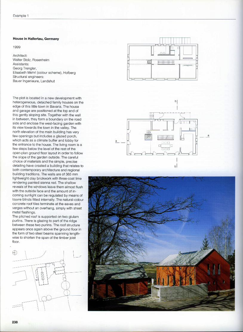
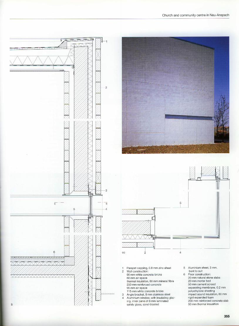
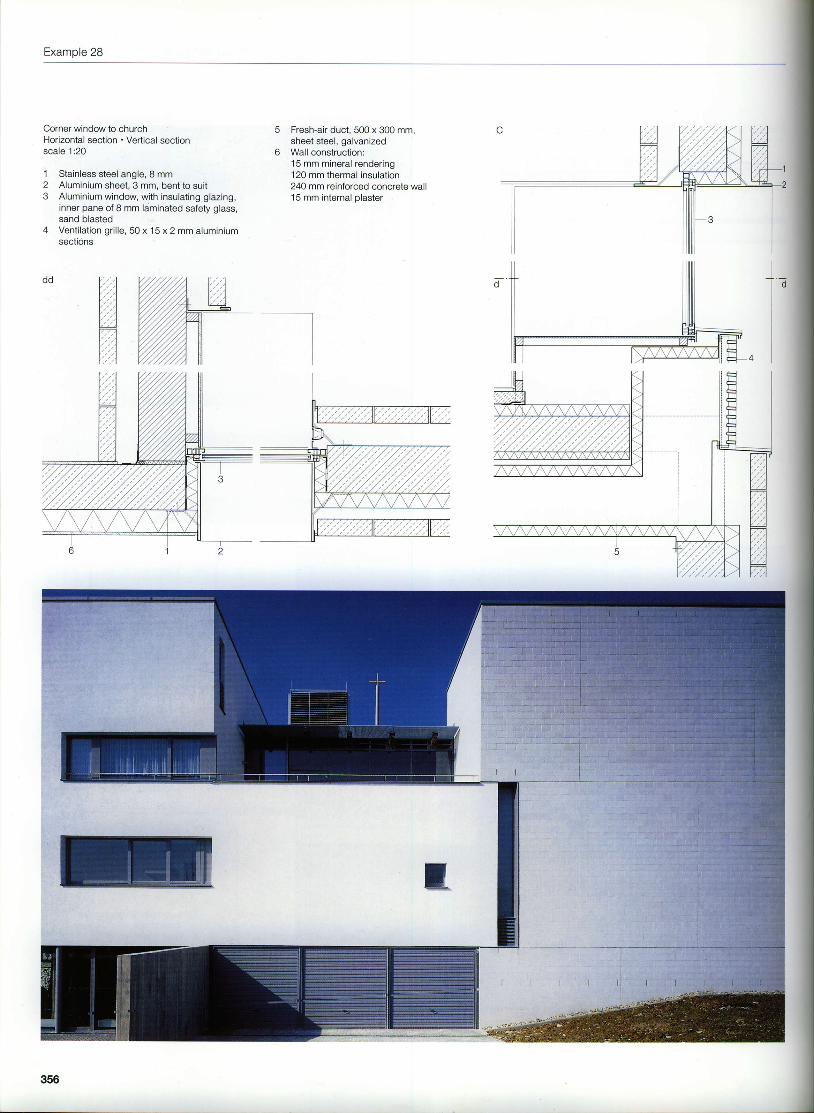
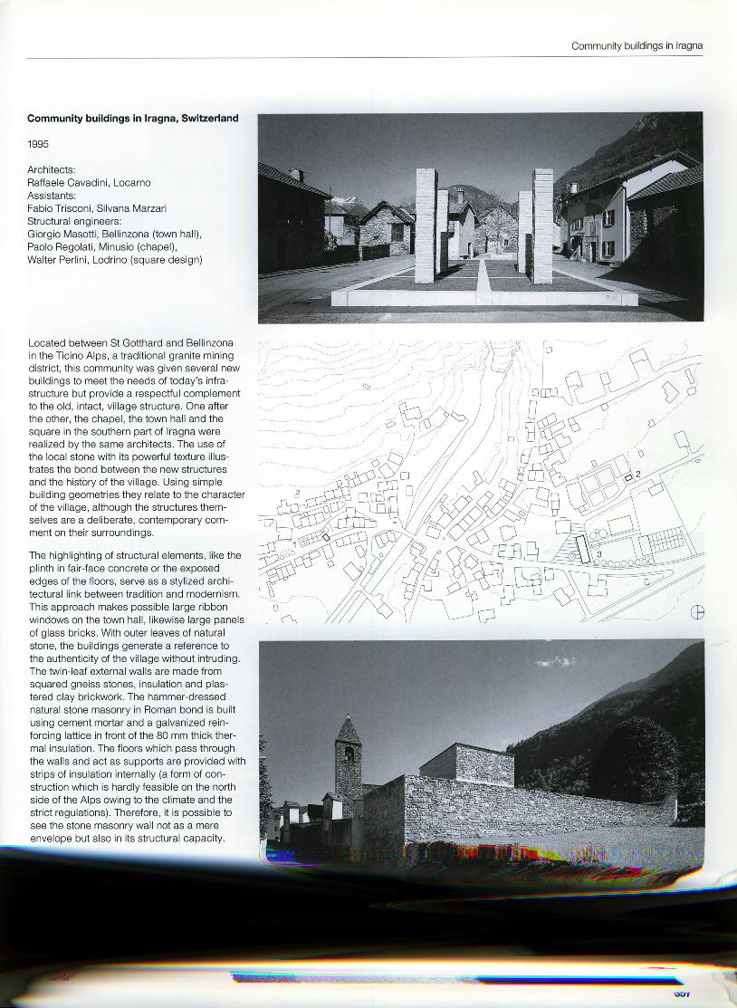
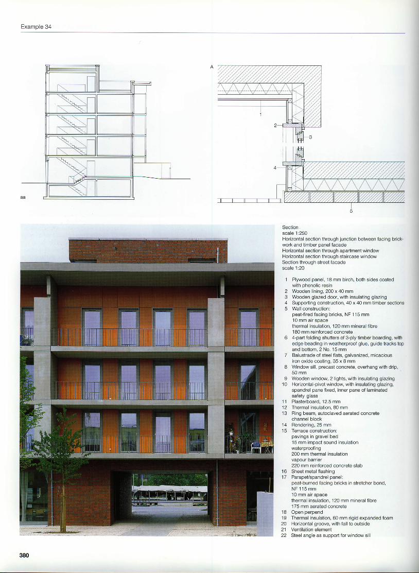
The plot is located in a new development withheterogeneous, detached family houses on theedge of this little town in Bavaria. The houseand garage are positioned at the top end ofthis gently sloping site. Together with the wallin between, they form a boundary on the roadside and enclose the west-facing garden withits view towards the town in the valley. Thenorth elevation of the main building has veryfew openings but includes a glazed porch,which acts as a climate buffer and lobby forthe entrance to the house. The living room is afew steps below the level of the rest of theopen-plan ground floor layout in order to followthe slope of the garden outside. The carefulchoice of materials and the simple, precisedetailing have created a building that relates toboth contemporary architecture and regionalbuilding traditions. The walls are of 365 mmlightweight clay brictaarork with three-coat limerendering painted sienna red. The shallowreveals of the windows leave them almost flushwith the outside face and the amount of in-coming sunlight can be regulated by means oflouvre blinds fitted internally. The natural-colourconcrete roof tiles terminate at the eaves andverges without an overhang, simply with sheetmetal flashings.The pitched roof is supported on two glulampurlins. There is glazing to part of the ridgebetween these two purlins. The roof structureappears once again above the ground floor inthe form of two steel beams spanning length-wise to shorten the span of the timber joistfloor.
ffi! u !
nf---lnn n n
House in Hallertau
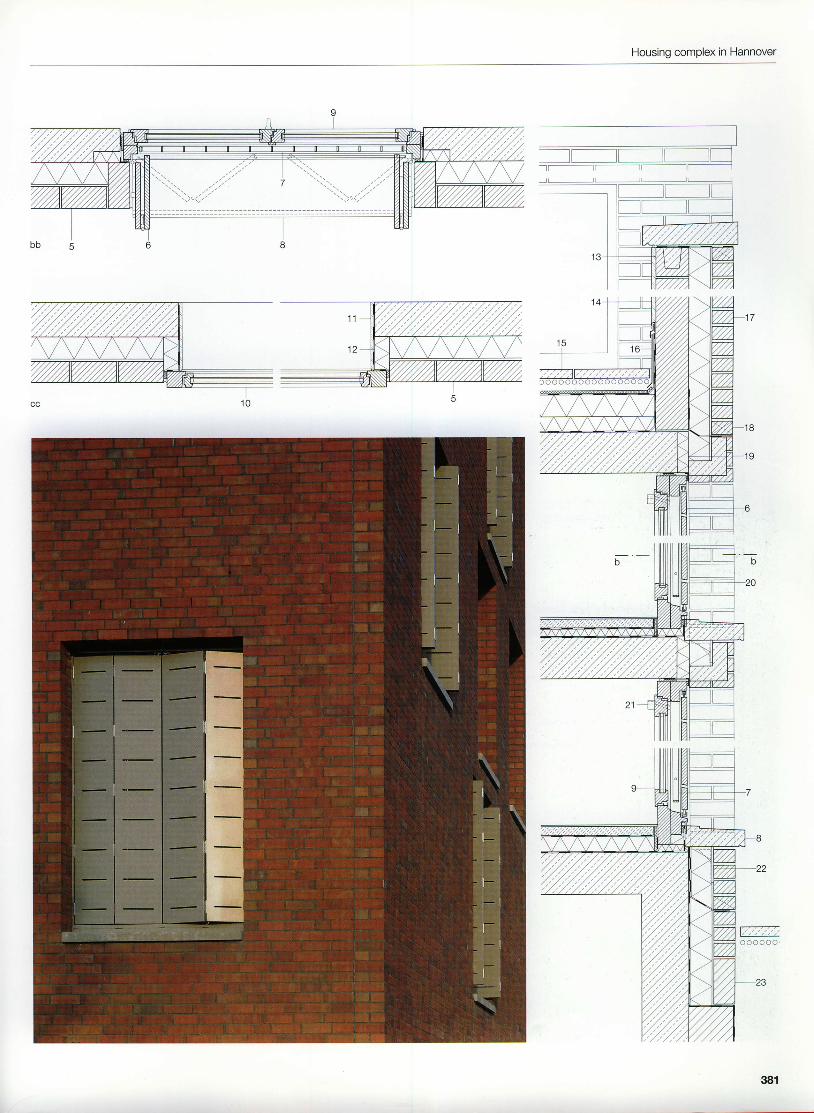
Site layoutscale 1 :10001st floorGround floorSectionsscale 1:250
239
Example.l
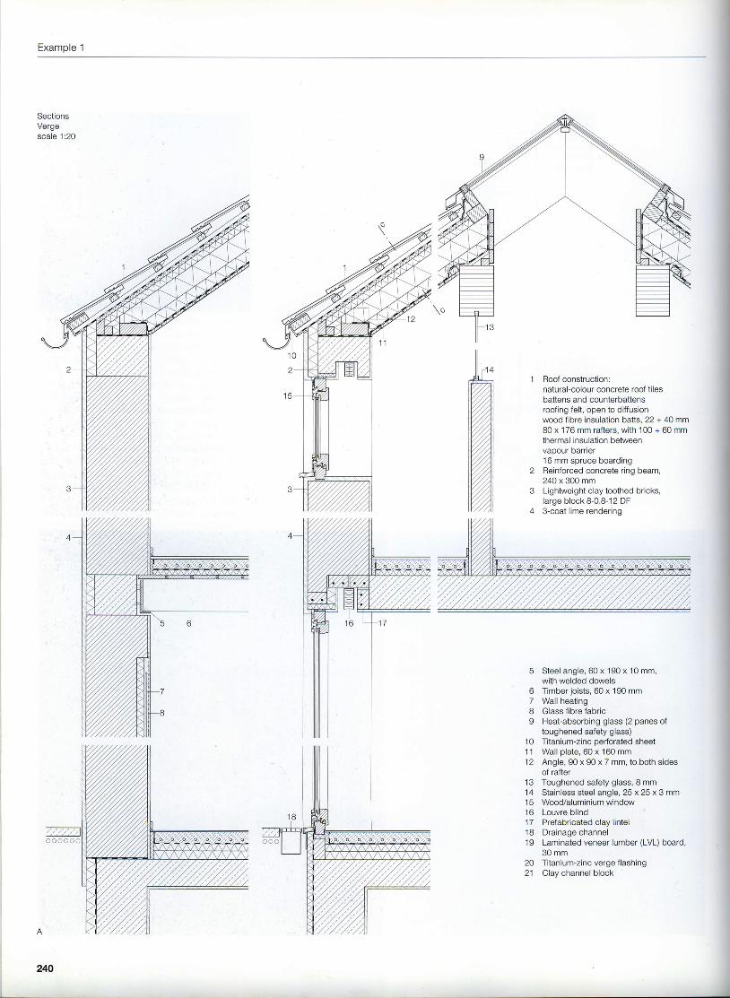
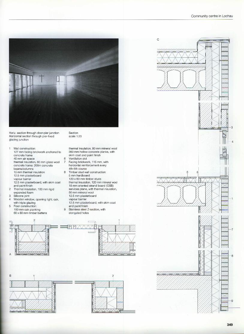
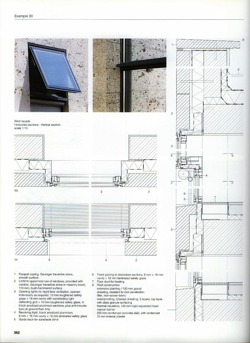
SectionsVergescale 1:20
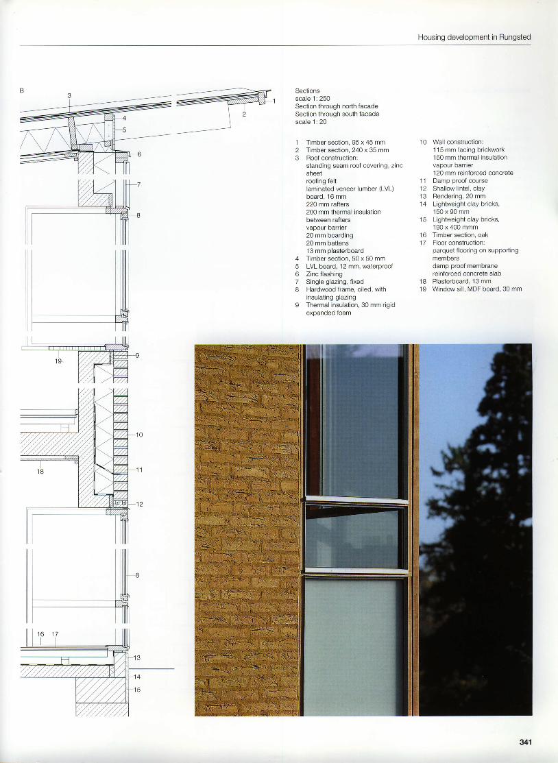
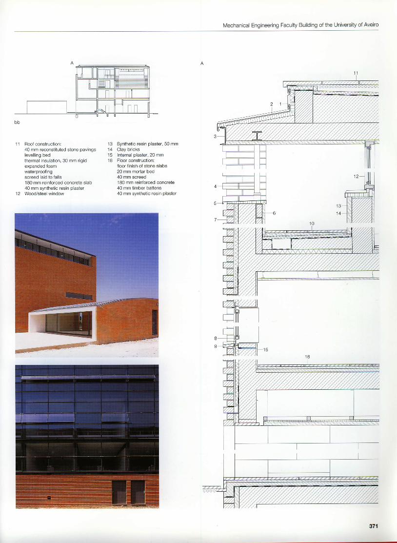
Roof construction:natural-colour concrete roof tilesbattens and counterbattensroofing felt, open to diffusionwood fibre insulation batts, 22 + 40 mm80 x 1 76 mm rafters, with 100 + 60 mmthermal insulation betweenvapour barner16 mm spruce boardingReinforced concrete ring beam,240 x 300 mmLightweight clay toothed bricks,large block 8-0.8-12 DF3-coat lime rendering
o7Iv
1 01 1
Steel angle, 60 x 190 x 10 mm,with welded dowelsTimber .ioists, 60 x 190 mmWall heatingGlass fibre fabricHeat-absorbing glass (2 panes oftoughened safety glass)Titanium-zinc pedorated sheetWall plate, 60 x 160 mmAngle, 90 x 90 x 7 mm, to.both sidesof rafter
13 Toughened safety glass, I mm14 Stainless steel angle, 25 x 25 x 3 mm15 WoocYaluminiumwindow16 Louvre blind17 Prefabricated clay lintel18 Drainage channel19 Laminated veneer lumber (LVL) board,
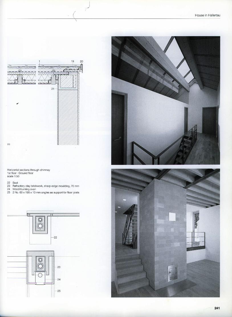
Horizontal sections through chimney1st floor . Ground floorscale 1:50
22 Seat23 Refractory clay briclarvork, sharp-edge moulding, 70 mm24 Wood-burning oven25 2 No. 60 x 190 x 10 mm angles as support for floor joists
241
Example 2
Housing complex in Ludwigsburg, Germany
1 998
Architects:Hartwig N. Schneider, with Gabriele Mayer,StuttgartProject architects:Andreas Gabriel, Ingo PelchenAssistant:FranzLuIz
n r^L.ait-t []lrr r'-
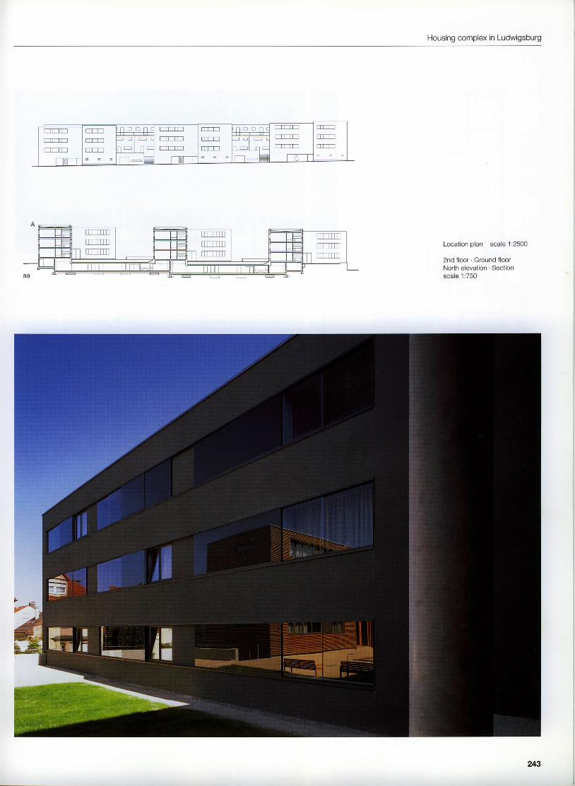
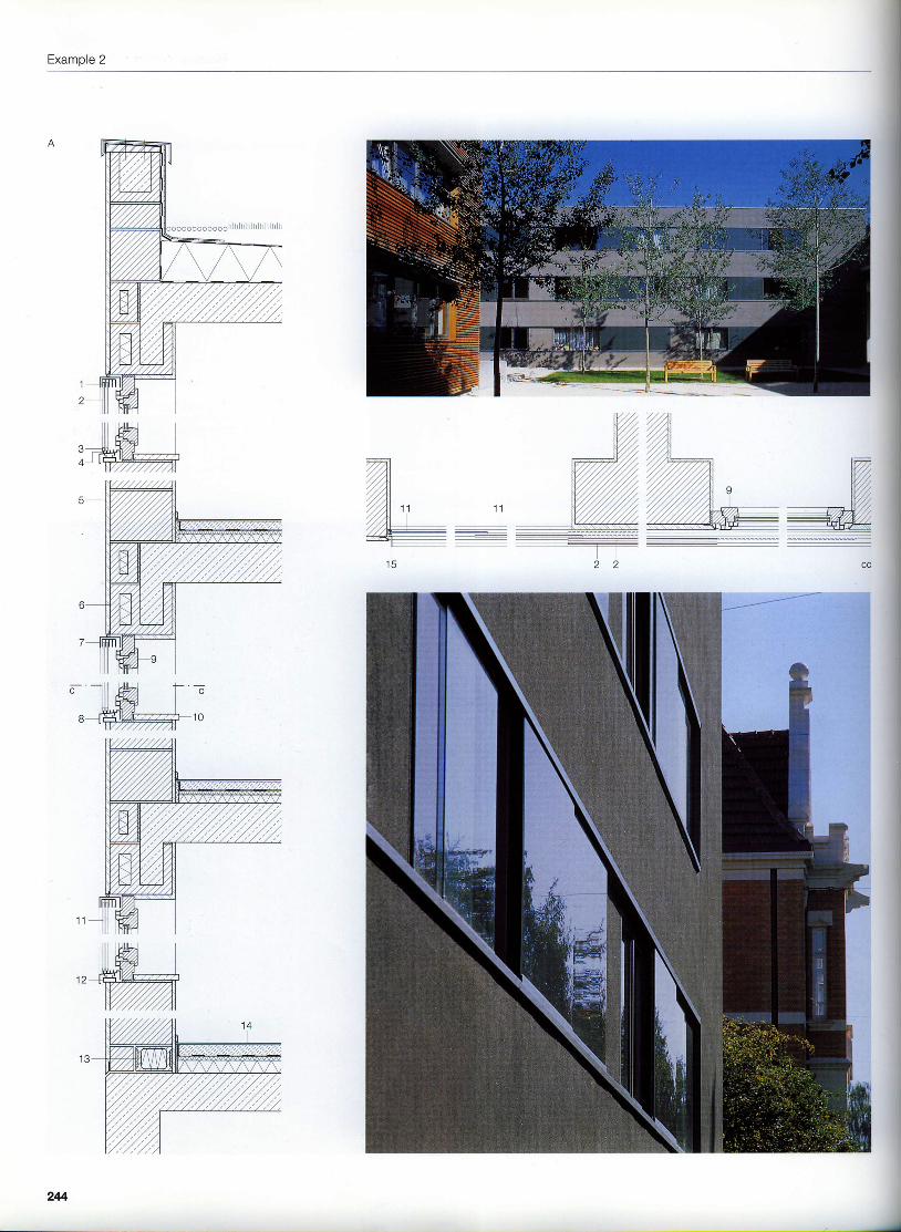
This housing complex, comprising a total of60 rented apadments distributed according totype among the group of three-storey blocks, islocated on the eastern edge of Ludwigburg'scity centre. There is one main block over 80 mlong which faces south, Attached to this arethree L-shaped wings on the road side, whoseend facades break up the streetscape. Theopen spaces between these wings contain theentrances to the basement garages and theoutside stairs to the landscaped courtyardsn r r o r t h o n a r e d a e
The building follows the topography with verysmall changes in height between the differentparts of the complex. Access to the apartmentsis by way of various staircase arrangements oran open walkway. All the housing units receivedaylight from at least two sides and face eitheronto the semi-public courtyards or the gardento the south. Further differentiation is providedby the different facade elements: ribbon win-dows with sliding wooden shutters alternatewith regular fenestration, cedar-clad accessblocks contrast with the areas of dark render-i ng .The walls of the blocks comprise, in the main,300 mm aerated clay brickwork covered with acoloured mineral rendering, The junctionsbetween the areas of rendering and adjoiningelements, such as windows and plinths, arecarefully detailed. The masonry on the longsouth elevation facing the garden is clad withcedar wood elements. Similar elements serveas sliding shutters to the room-height glazing.The balconies are precast concrete units sus-pended in front ofthe facade andprovided with a thermal break.
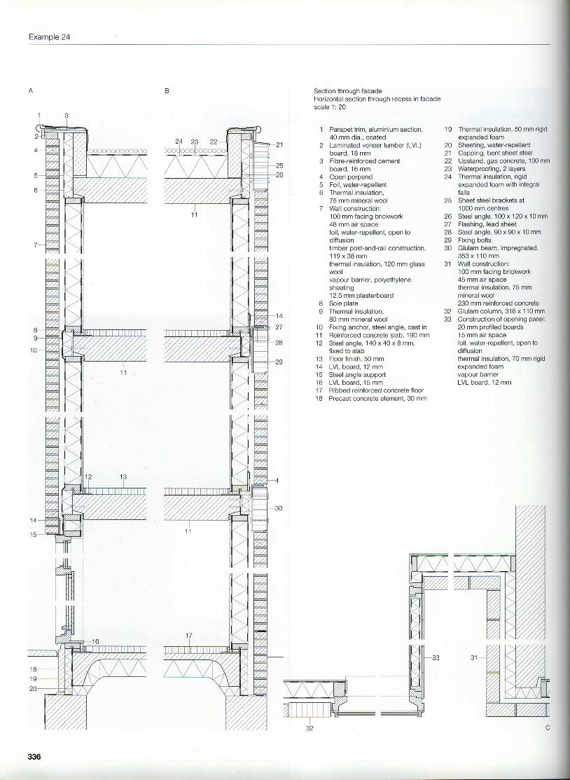
Section through west facade 14Horizontal section through sliding glazing inrendered facade scale 1:20Section scale 11500Section throuoh south facade scale 1:20
Aluminium track, with brushesToughened safety glass, I mm,rear face enamelledAluminium guide shoe, with guide wheelAlumrnium trackWall construction:20 mm mineral rendering300 mm Hlz lightweight clay bricks15 mm internal plaster
6 Lightweight clay channel block, 300 mm7 Aluminium channel , 100 x 50 x 5 mm8 Aluminium external window sillI Wood/aluminium window with insulating glazing
10 Reconstituted stone internal window sill11 Toughened safety glass, S mm12 Steel hollow section, 60 x 20 x 3 mm, galvanized13 Thermal insulat ion element, loadbear ing
Floor constructionl5 mm floor covering50 mm cement screed0.2 mm polyethylene separating membrane20 mm impact sound insulation60 mm thermal insulation180 mm reinforced concrete slabAluminium angle, 60 x 30 x 5 mmParapet cladding: 14 mm cemenlboundwood fibre board
15 mm internal plaster240 mm Hlz lightweight clay bricks80 mm mineral wool thermal insulationprotective covering (non-woven fabric)prefabricated cedar wood cladding, 58 mm
21 Timber closing piece, 22o x 48 mm22 Precast concrete element, coloured23 Balustrade of steel sections, galvanized,
colour-coated
ilillH
""1-l l q l nh hR hH hh hR Ah \SF
N
hhs\s
245
Example 3
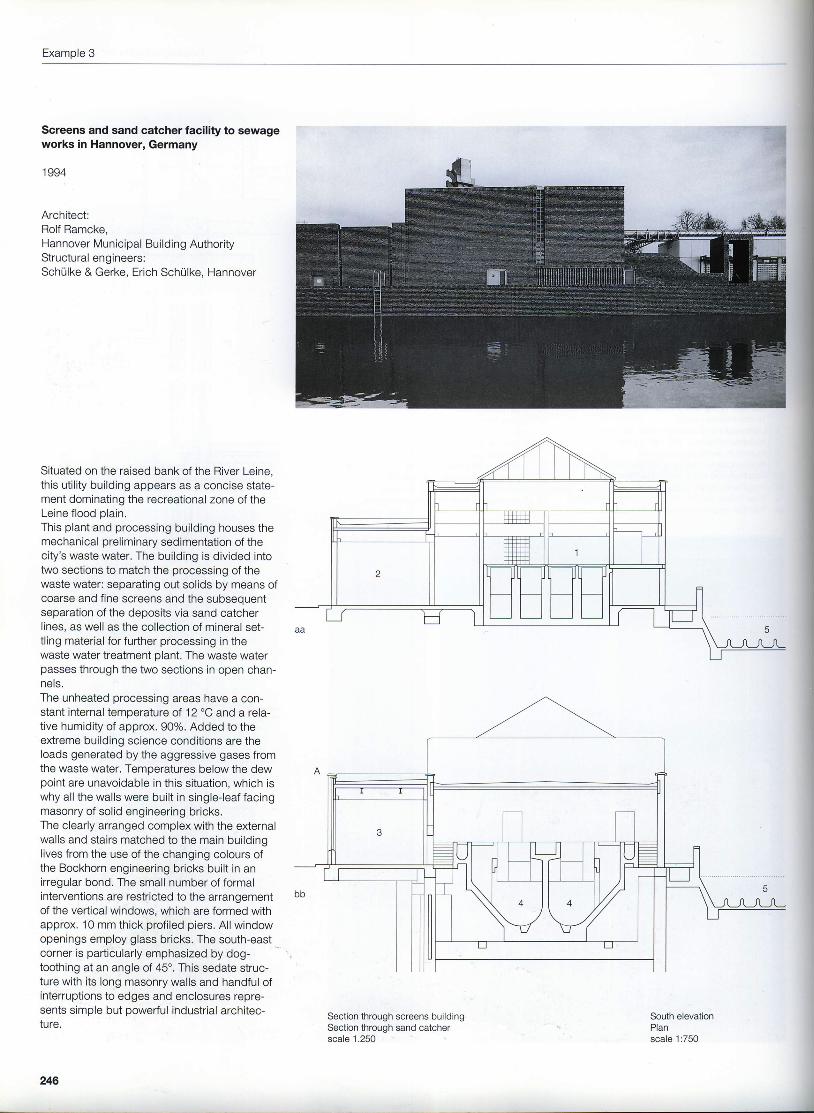
Screens and sand catcher facility to sewageworks in Hannover, Germany
1 994
Architect:Rolf Ramcke,Hannover Municipal Building AuthorityStructural engineers:Schulke & Gerke, Erich Schulke, Hannover
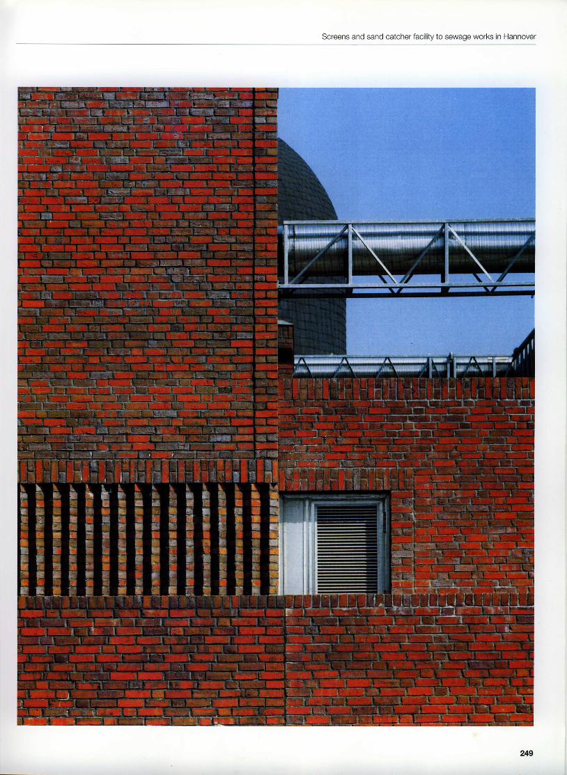
Situated on the raised bank of the River Leine,this uti l i ty building appears as a concise state-ment dominating the recreational zone of theLeine flood plain.This plant and processing building houses themechanical preliminary sedimentation of thecity's waste water. The building is divided intotwo sections to match the processing of thewaste water: separating out solids by means ofcoarse and fine screens and the subsequentseparation of the deposits via sand catcherlines, as well as the collection of mineral set-tl ing material for further processing in thewaste water treatment plant. The waste waterpasses through the two sections in open chan-nels.The unheated processing areas have a con-stant internal temperature of 12 "C and a rela-tive humidity of approx. 90%. Added to theextreme building science conditions are theloads generated by the aggressive gases fromthe waste water. Temperatures below the dewpoint are unavoidable in this situation, which iswhy all the walls were built in single-leaf facingmasonry of solid engineering bricks.The clearly arranged complex with the externalwalls and stairs matched to the main buildinglives from the use of the changing colours ofthe Bockhorn engineering bricks built in anirregular bond. The small number of formalinterventions are restricted to the arrangementof the vertical windows, which are formed withapprox, 10 mm thick profi led piers. All windowopenings employ glass bricks. The south-eastcorner is particularly emphasized by dog-toothing at an angle of 45'. This sedate struc-ture with its long masonry walls and handful ofinterruptions to edges and enclosures repre-sents simple but powerful industrial architec-ture.
Section through screens buildingSection through sand catcherscale 1,250
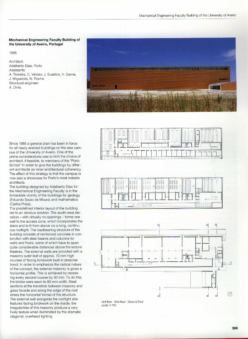
South elevationPlanscale 1:750
246
Screens and sand catcher facility to sewage works in Hannover
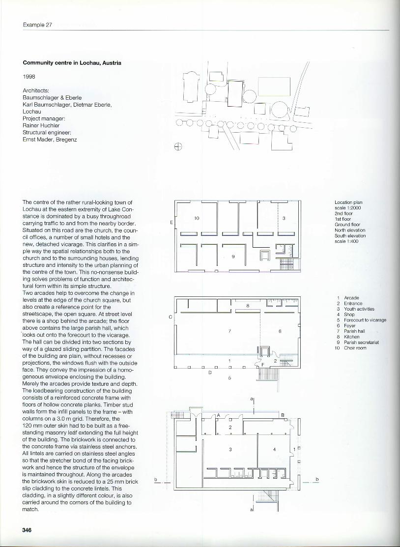
1 Screens building2 Screens containers3 Sand screening4 Sand catcher lines I and ll5 Rainwater retention basin6 Inlet pumping plant I
247
Example 3
Section through north facadeHorizontal section through windowsElevation on and section through doorscale 1:20
Sheet metal cappingNF engineering bricksThermal insulation, 40 mmRoof construction:50 mm gravelwaterproofing, 3 layersthermal insulation with 1.57o fall,150-270 mmvapour barrier
vapour pressure compensationmemDrane200 mm lightweight concretepranKSFloor construction:50 mm reconstituted stone tiles30 mm mortar bedpolyethylene separating membraneStainless steel channel, 80 mm
Screens and sand catcher facility to sewage works in Hannover
249
Example 4
Extension to school in Gebenstorf,Switzerland
1 997
Architects:Urs Burkard, Adrian Meyer & Partner, BerlinAssistants:Daniel Krieg, Adrian StreichStructural engineers:Gerber + Partner, Munich
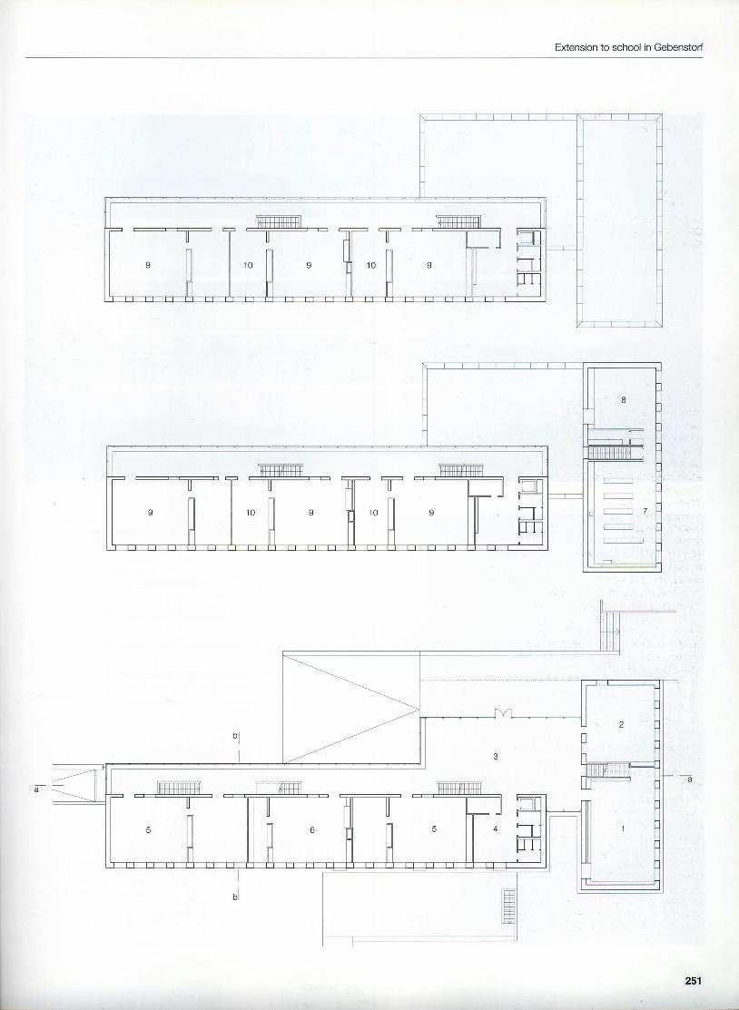
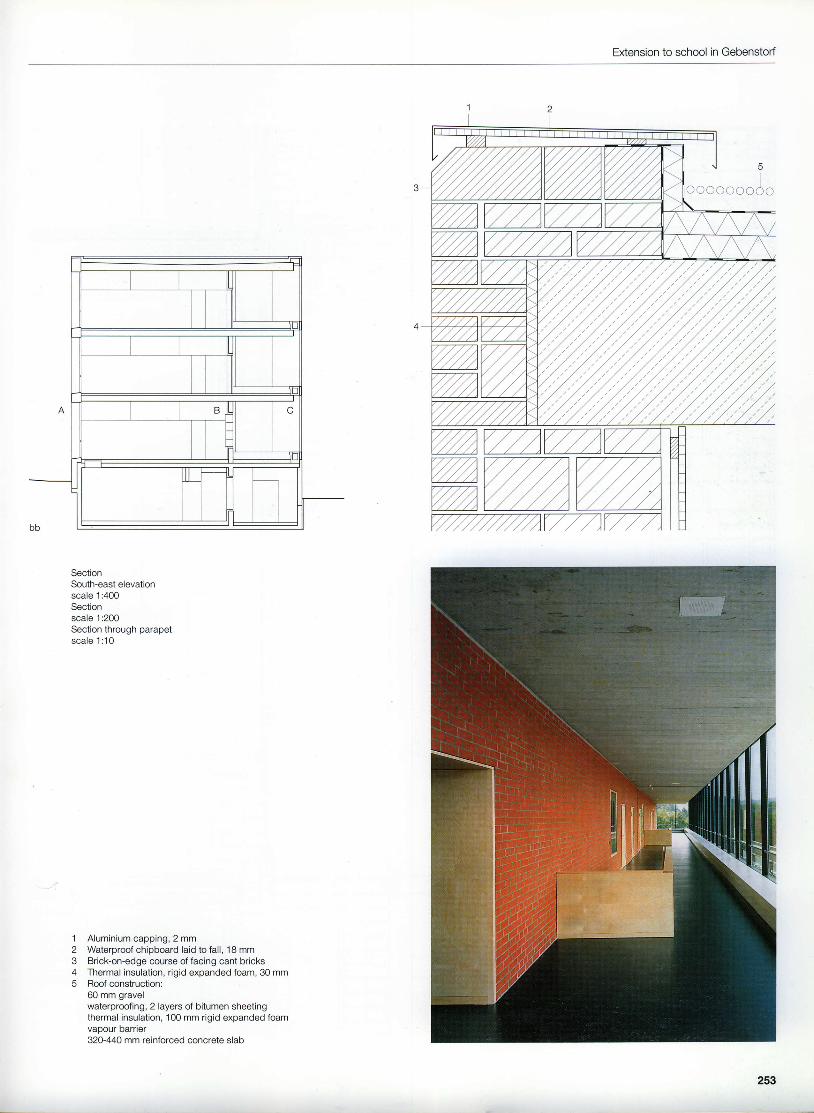
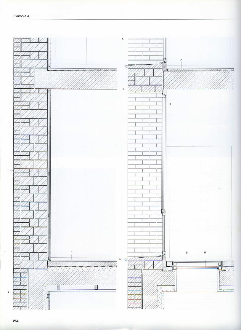
This extension to the existing school complexconsists of two sections; a three-storey class-room wing facing south, and to the east a two-storey block with staff-room and library plus theschool kitchen on the upper floor. The northfacade of the three-storey block forms theboundary to the school yard and featuresstorey-height glazing, which permits a view ofthe stairs and the internal walls with their win-dows to the classrooms.The buildings, the proportions of which remindus of bricks, are built entirely of masonry:single-leaf 610 mm external walls clad intern-ally, and 250 mm internal walls with facingbrickrryork on both sides. The tension whichresults from the heaviness of the brick volumesand the lightness of the glazing helps to createthis impressive architectural statement.The 320 mm reinforced concrete floor slabsare prestressed to support the cantilever.Their good heat storage capacity reinforcesthe simple energy concept of the building.The single-leaf wall construction employs aprecisely specified two-layer composite. Hardclay bricks on the outside with a bulk density of1800 kg/ms have been combined with aeratedmasonry units with a bulk density of 1400 kg/m3,Within the masonry bond, every fourth courseof engineering bricks penetrates deeper intothe external wall. This construction achieves aU-value of 0.34 Wm2K, which lies within thestatutory requirements for this type of building.The advantages of this system found expres-sion in the architecture - the south elevation,with tall, simple window slits and deep reveals,does not require any sunshading. The class-room walls adjacent to the corridors alsoinclude window openings to enable thosepassing to observe the activities within. Thisschool has pointed a new way forward formasonry construction in terms of the preciseimplementation of the building concept and thecredibil i ty of the design and the details.
2ffi
Location plan scale 12nd floor1st floorGround floorscale 1:400
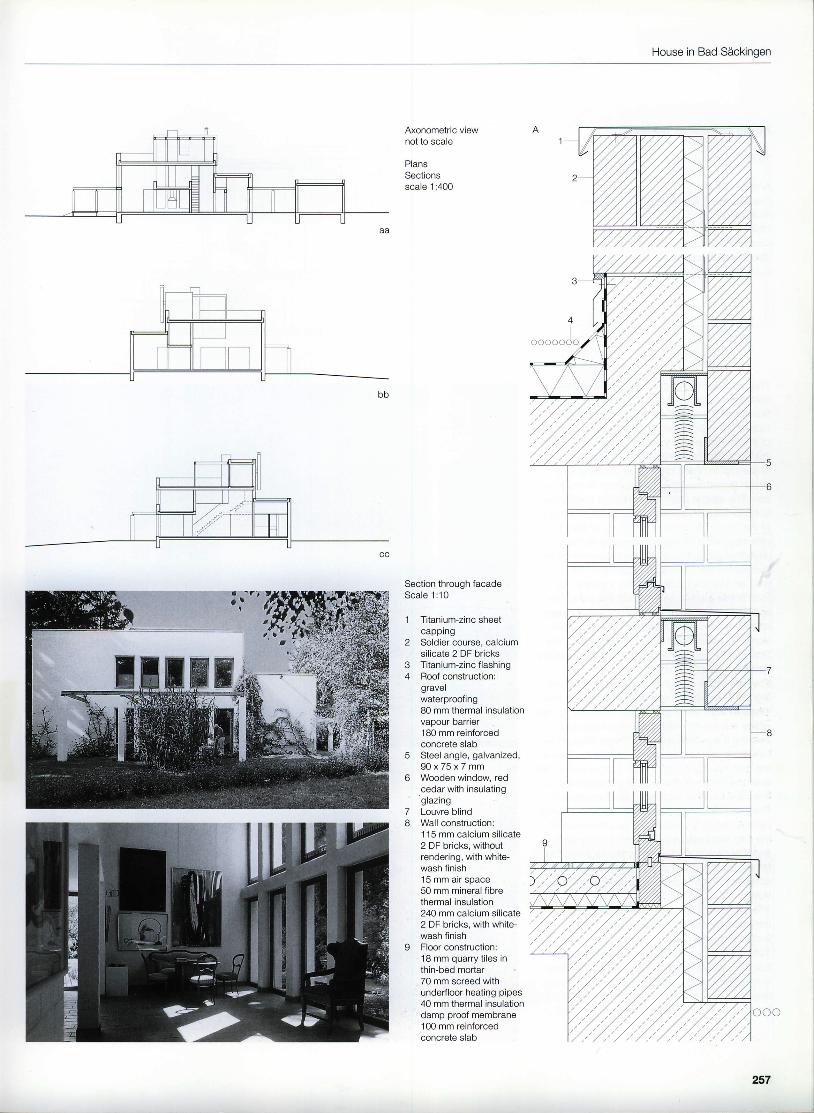
This house stands on the north-west boundaryof a plot where in the past it formed a counter-weight to a villa dating from the Bauhaus era,which has since been demolished. The ownerspossess an extensive collection of contempo-rary art.In order to provide an appropriate setting forthe paintings, with differentiated lighting, theinternal rooms are of different heights.The shape ofthe house is based on a squareplan which includes large rooftop terraces ontwo sides.The garage and a pergola, which denote theentrance, enclose a small play area in front ofthe children's bedrooms. The building is setout on a 1.25 m grid. The calcium sil icatemasonry left exposed internally and externallywas whitewashed after the joints were finishedin the same operation as the bricklaying.Just two different window sizes with blindsbehind the soldier course lintels determine thesimplistic appearance of the house.The details which would today no longer beacceptable from the building science viewpointhave not led to any damage to the buildingthanks to the extensive low-temperature heat-ing at ground floor level.
" ' f 'u. l
256
House in Bad Sdckingen
Axonometric viewnot to scale
PlansSectionsscale 1:400
Section through facadeSca le 1 :10
3
78
5
o
Titanium-zinc sheetcappingSoldier course, calciumsilicate 2 DF bricksTitanium-zinc f lashingRoof construction:gravelwalerproofing80 mm thermal insulationvapour barrier180 mm reinforcedconcrete slabSteel angle, galvanized,g u x / b x / m mWooden window, redcedar with insulatinggrazrngLouvre blindWall construction:115 mm calc ium si l icate2 DF bricks, withoutrendering, with white-wash finish15 mm air space50 mm mineral fibrethermal insulation240 mm calcium silicate2 DF bricks, with white-wash finishFloor construction:18 mm quarry tiles inthin-bed mortar70 mm screed withunderfloor heating pipes40 mm thermal insulationdamp proof membrane100 mm reinforcedconcrete slab
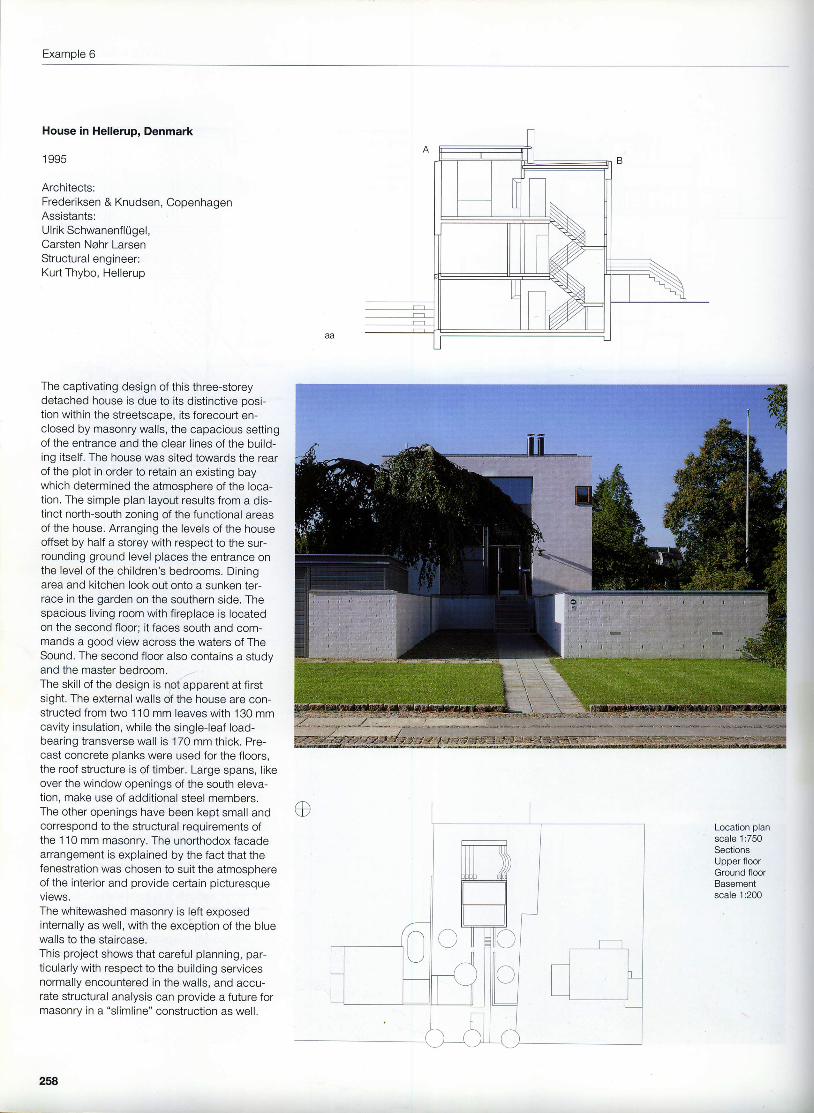
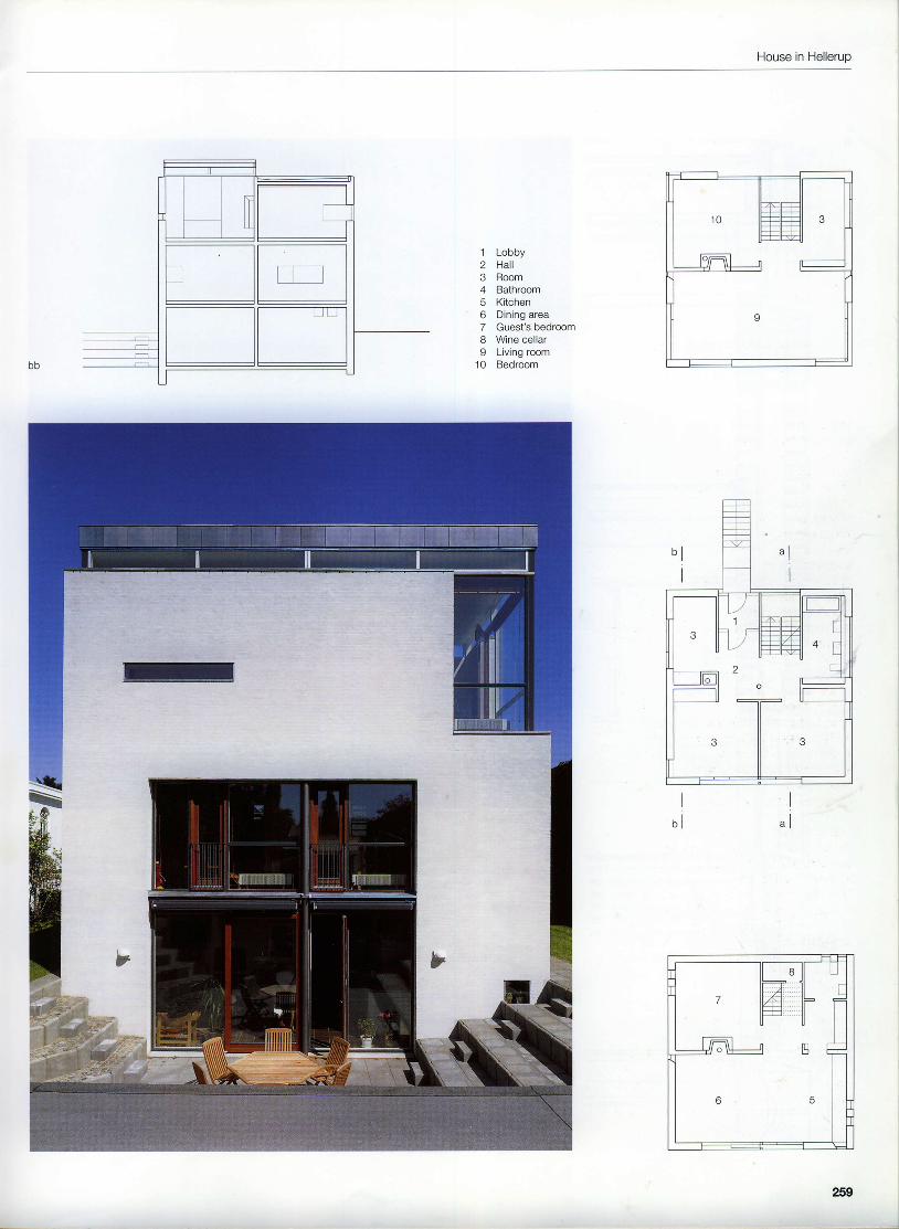
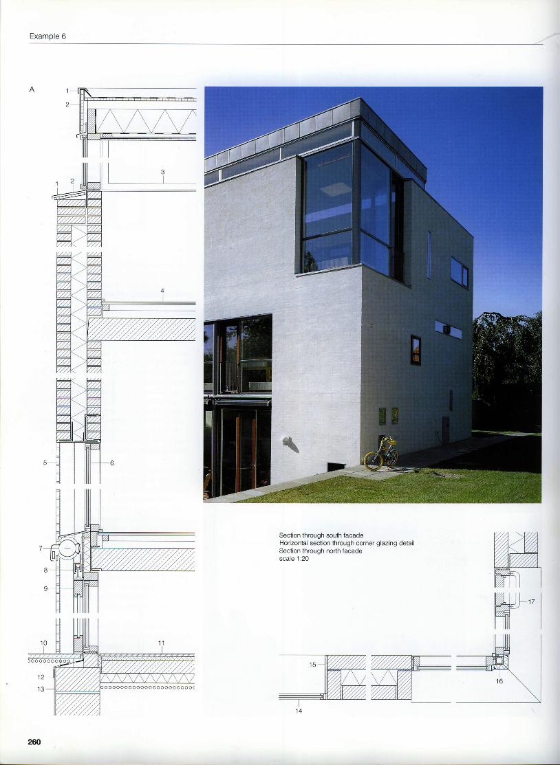
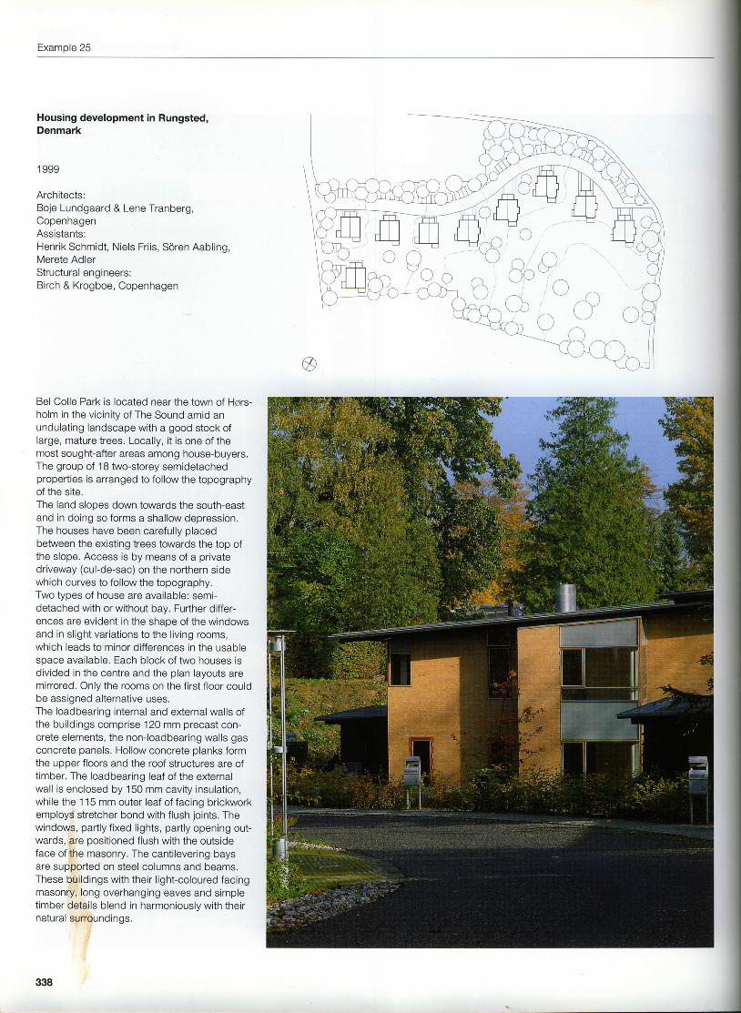
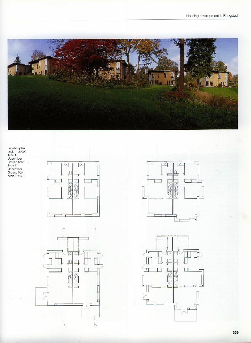
The captivating design of this three-storeydetached house is due to its distinctive posi-tion within the streetscape, its forecourt en-closed by masonry walls, the capacious settingof the entrance and the clear lines of the build-ing itself. The house was sited towards the rearof the plot in order to retain an existing baywhich determined the atmosphere of the loca-tion. The simple plan layout results from a dis-tinct north-south zoning of the functional areasof the house. Arranging the levels of the houseofiset by half a storey with respect to the sur-rounding ground level places the entrance onthe level of the children's bedrooms. Diningarea and kitchen look out onto a sunken ter-race in the garden on the southern side. Thespacious living room with fireplace is locatedon the second floor; it faces south and com-mands a good view across the waters of TheSound. The second floor also contains a studyand the master bedroom.The skill of the design is not apparent at firstsight. The external walls of the house are con-structed from two 110 mm leaves with 130 mmcavity insulation, while the single-leaf load-bearing transverse wall is 170 mm thick. Pre-cast concrete planks were used for the floors,the roof structure is of timber. Large spans, likeover the window openings of the south eleva-tion, make use of additional steel members.The other openings have been kept small andcorrespond to the structural requirements ofthe 110 mm masonry. The unorthodox facadearrangement is explained by the fact that thefenestration was chosen to suit the atmosphereof the interior and provide certain picturesqueviews.The whitewashed masonry is left exposedinternally as well, with the exception of the bluewalls to the staircase.This project shows that careful planning, par-ticularly with respect to the building servicesnormally encountered in the walls, and accu-rate structural analysis can provide a future formasonry in a "slimline" construction as well.
Section through south facadeHorizontal section through corner glazing detailSection through north facadescale 1:20
l%))1,,tffil
260
House in Hellerup
20
22
Wooden planks, courbarilLightweight concrete slab, 180 mmChipboard, 20 mmDoormatSteel open-grid flooringSteel angle, 80 x 80 mmReinforced concrete wall, 135 mm
23
24
1 Sheet zinc cappingLaminated veneer lumber (LVL), 16 mmWindow frame,50 x 100 x 3.2 mm st€el hollow sectionFloor construction:20 mm wooden planks50 x 50 mm timber supporting constructiontimber levelling layer180 mm lightweight concrete slabColumn, 115 mm dia. steel circular hollow sectionWoocyaluminium window, with insulating glazingExtending marquiseSliding door fittingsSliding doorConcrete paving slabsFloor construction:20 mm natural stone tiles in varying lengths30 mm mortar bed100 mm reinforced concrete75 mm rigid mineral wool20O mm gravelBitumen sheeting, welded onLightweight concrete brickworkInsulating glazing, flush with outside face
15 Reinforced olaster16 Corner column, 60 x 60 x 4 mm steel hollow section17 Guard rail mounted on window frame18 Roofconstruction:
waterproofing21 mm wateroroof LVLFirring pieces75x2OO mm raftersthermal insulation, 180 mm mineral woolvaoour barrier50 x 50 mm battens13 mm plasterboard, 2 layersWall construction:115 mm clay brickwork with whitewash finish110 mm thermal insulation1 15 mm clay brickwork with whitewash finishSteel angle, 100 x 150 x 10 mmSteel angle, 75 x 100 x I mmCavity closer, 2 mm aluminium sheetCladding, aluminium sheetSteel channel. 220 mmSteel angle, 50 x 30 x 4 mm, with white coatingGlass door to lobbyEntrance doors
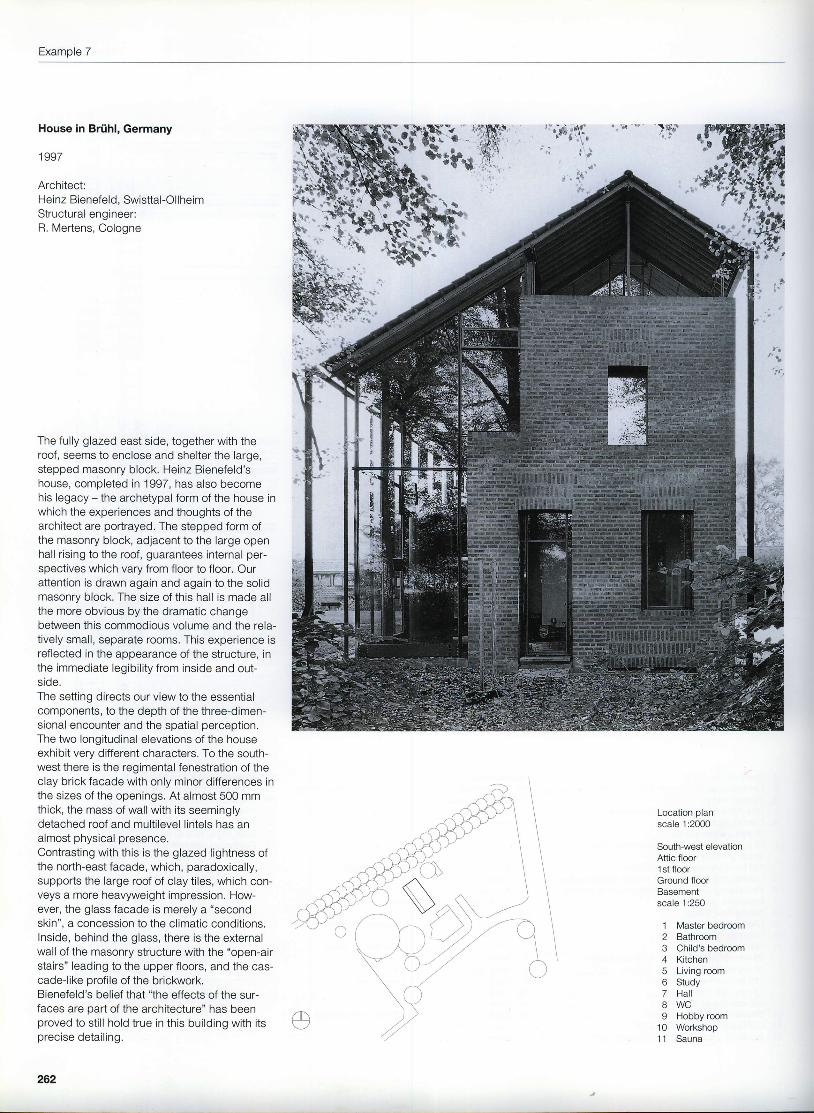
The fully glazed east side, together with theroof, seems to enclose and shelter the large,stepped masonry block. Heinz Bienefeld'shouse, completed in 1997, has also becomehis legacy - the archetypal form of the house inwhich the experiences and thoughts of thearchitect are portrayed. The stepped form ofthe masonry block, adjacent to the large openhall rising to the roof, guarantees internal per-spectives which vary from floor to floor. Ourattention is drawn again and again to the solidmasonry block. The size of this hall is made allthe more obvious by the dramatic changebetween this commodious volume and the rela-tively small, separate rooms. This experience isreflected in the appearance of the structure, inthe immediate legibility from inside and out-side.The setting directs our view to the essentialcomponents, to the depth of the three-dimen-sional encounter and the spatial perception.The two longitudinal elevations of the houseexhibit very different characters. To the south-west there is the regimental fenestration of theclay brick facade with only minor differences inthe sizes of the openings. At almost 500 mmthick, the mass of wall with its seeminglydetached roof and multilevel lintels has analmost physical presenceContrasting with this is the glazed lightness ofthe north-east facade, which, paradoxically,supports the large roof of clay tiles, which con-veys a more heavyweight impression. How-ever, the glass facade is merely a "secondskin", a concession to the climatic conditions.lnside, behind the glass, there is the externalwall of the masonry structure with the "open-airstairs" leading to the upper floors, and the cas-cade-like profile of the brickwork.Bienefeld's belief that "the effects of the sur-faces are part ofthe architecture" has beenproved to still hold true in this building with itsprecise detail ing.
I[--_-]l_E_E t-t t-t t-t t-t t-t t-t t-t u t.t t-t t-t t-t I I [-] E r---_-] r_:_tr--rl l l l l i l i l i l I l i l i l i l l l l l l l l l l l lr--_-]I r---_l E t_l L_l L_l L_l L_l L_J L_l L_l L_l L_l t_l Ll L_l L_l L_l I] r---_-] ftr--rr-__l n t_-l t_-l t_-l t] tl tl t-t t-t n i-t t-t r--_-] r-r r----lr---_-]El
ll ll ll ll ll ll ll ll ll 11 ll lrrr----_-1Ir--_-1r--_-] ! ! L l ! L l L l ! t__l L_l L_l t_l L_l r---]r--_lrr r--_l E tl t-t t- t t-t t-t t-t t-t t-t t-t t-.1 tl n t-t E r--_-] r'tf-------__lt--------l
llrl llrl llrl llrl llll llll lf------__lt---ltl r i l r l l t_- l l l f_ l l l f_ l l ln l l f ] l f ] l l i l rL
][--_-]t]l l l l l l l l l l l l l l l l l l l l l l l l l lE[---_-][
[--_-]l
t----lI
lr---l
I[--_-1
f f ul-ll!!L_tL_tLrt[lttIrtt | il tl-__lL lL lL_. lL
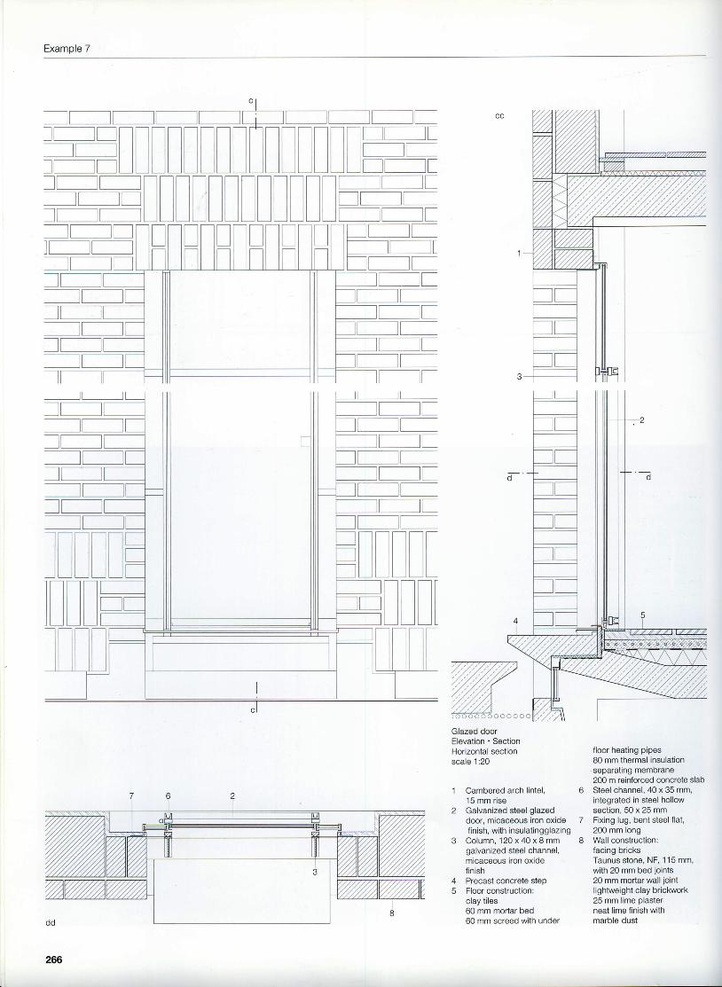
2 Galvanized steel glazeddoor, micaceous iron oxidefinish, with insulatingglazing
3 Column, 120 x 40 x I mmgalvanized steel channel,micaceous iron oxidefinish
4 Precast concrete step5 Floor construction:
clay tiles60 mm mortar bed60 mm screed with under
floor heating pipes80 mm thermal insulationseparating membrane200 m reinforced concrete slabSteel channel, 40 x 35 mm,integrated in steel hollowsection, 50 x 25 mmFixing lug, bent steel flat,200 mm longWall construction:facing bricksTaunus stone, NF, 1 15 mm,with 20 mm bed Joints20 mm mortar wall jointlightweight clay brickwork25 mm lime Dlasterneat lime finish withmarble dust
o
7
I
266
Housing complex in Lonach
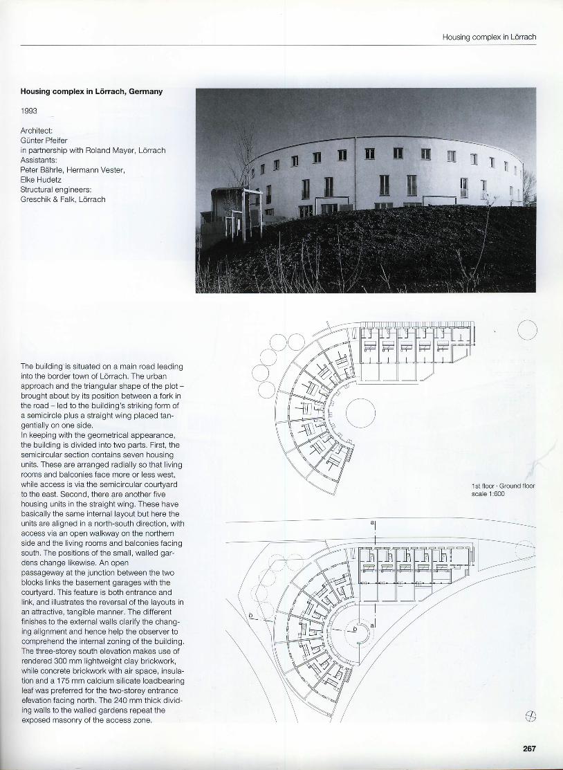
Housing complex in Liirrach, Germany
I OOe
Architect:Gunter Pfeiferin partnership with Roland Mayer, LorrachAssistants:Peter B6hrle, Hermann Vester,Elke HudetzStructural engineers:Greschik & Falk, Lorrach
The building is situated on a main road leadinginto the border town of Lorrach. The urbanapproach and the triangular shape of the plot -brought about by its position between a fork inthe road - led to the building's striking form ofa semicircle plus a straight wing placed tan-gentially on one side.In keeping with the geometrical appearance,the building is divided into two parts. First, thesemicircular section contains seven housingunits. These are arranged radially so that livingroorns and balconies face more or less west,while access is via the semicircular courtyardto the east. Second, there are another fivehousing units in the straight wing. These havebasically the same internal layout but here theunits are aligned in a north-south direction, withaccess via an open walkway on the northernside and the living rooms and balconies facingsouth. The positions of the small, walled gar-dens change likewise. An openpassageway at the junction between the twoblocks links the basement garages with thecourtyard. This feature is both entrance andlink, and illustrates the reversal of the layouts inan attractive, tangible manner. The differentfinishes to the external walls clarify the chang-ing alignment and hence help the observer tocomprehend the internal zoning of the building.The three-storey south elevation makes use ofrendered 300 mm lightweight clay brickrivork,while concrete brickwork with air space, insula-tion and a 175 mm calcium silicate loadbearingleaf was preferred for the two-storey entranceelevation facing north. fhe 24Q mm thick divid-ing walls to the walled gardens repeat theexposed masonry of the access zone.
Concrete lintelWooden window with insulating glazingWall construction:90 mm concrete bricks in stretcher bond40 mm air soace60 mm thermal insulation175 mm calcium silicate bricks15 mm lime-cement olaster
)I
tr
268
Housing complex in Lonach
269
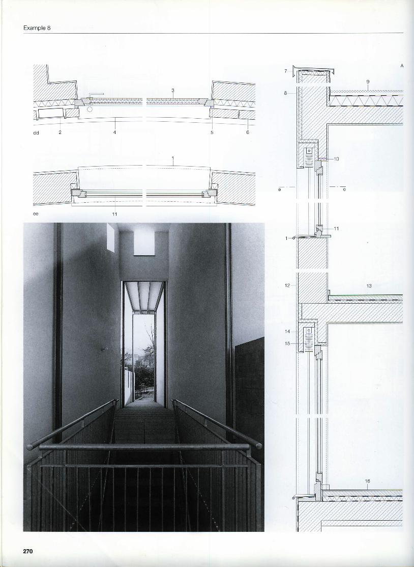
Example 8
270
Housing complex in Lorrach
2J
56
Window sill, titanium-zincsheetLetter boxEntrance doorDoor threshold,5 mm galvanized steelsheetCavity closerWall construction:90 mm concrete bricks40 mm air space60 mm thermal insulation'175 mm calcium silicatebricks15 mm lime-cementplasterParapet capping,titanium-zinc sheetParapet construction:20 mm renderingthermal insulation, 35 mmrigid expanded foamreinforced concrete wallthermal insulation, 25 mmrigid expanded foamwaterproofing
I Roof construction:50 mm gravelwaterproofingthermal insulation,100 mm rigid expanded foamvapour barrier180 mm RC slab15 mm lime-cement plaster
10 Thermal insulation, 25 mm11 Wooden window with
insulating glazing12 Wall construction:
20 mm rendering30O mm ltM clay bricks15 mm lime-cement plaster
13 Floor construction:linoleum45 mm screedseparating membrane30 mm thermal insulation200 mm RC slab15 mm lime-cement plaster
waterproofing24 mm timber boarding1 20 x 180 mm rafters120 mm thermal insulation25 mm timber battens15 mm plasterboardRoller blind box,'100 x 100 mmSteel angle, 120 x 80 x 8 mm
Horizontal sectionsConcrete brick facade '
Rendered facadeVertical sectionsscale 1:20
21
271
Example 9
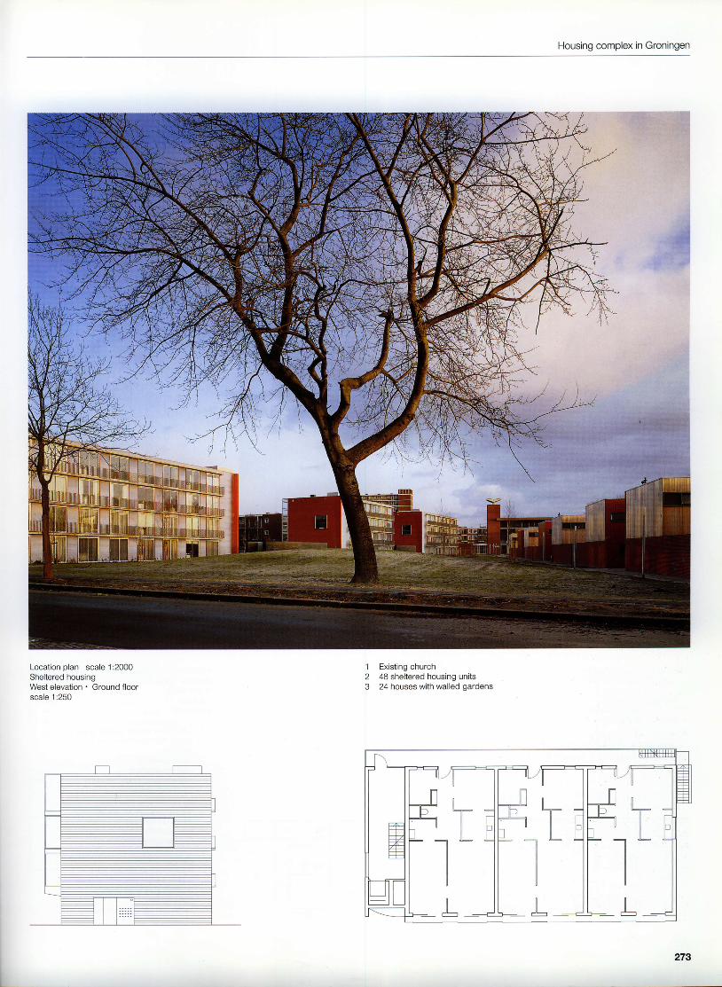
Housing complex in Groningen,The Netherlands
1993
Architects:Felix Claus, Kees Kaan, AmsterdamAssistant:Andrew DawesStructural engineers:Ingenieurb0ro Wassenaar, Haren
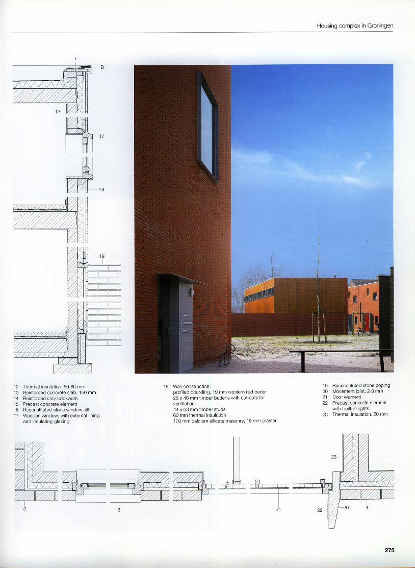
The surrounding streets and paths determinethe urban arrangement of the whole complex,which forms an intermittent boundary on twosides of a triangular park open at the west end.On the south-west side there are terracedhouses with walled gardens, while on the nodh-east side there are three blocks containingapartments. These form the backbone of thecomplex, split up by the intervening accesspaths and play areas, On the southern sidefacing the park, the apartments are fully glazedwith slim balconies. On the other side, facingthe road, the open wallouays on the upperfloors are well lit via the generous expanse ofglazing. The slim apartments contain two deeprooms facing south-west, which can be usedas living room, bedroom or study as required.The kitchen and a further room lie on the walk-way side.The terraced houses on the southern boundaryof the site are arranged in groups of six, separ-ated from each other by narrow accesspassageways.The loadbearing construction consists of twin-leaf masonry walls with precast concrete floors.The external surfaces - red facing brickworkadjacent the alleyways, vertical timber board-ing facing the gardens and on the gables - areskilfully related to each other. On the groundfloor the almost square houses are divided intoan entrance lobby, kitchen and living/diningarea. A winding stair leads from the lobby up tothe first floor, which contains three rooms and asmall, separate toilet, plus bathroom. The planlayouts are such that the houses could bedivided into separate apartments on groundfloor and first floor at a later date. The apart-ment blocks are differentiated in a similar fash-ion: storey-height sliding windows in front ofglass facades on the park side, clay brickworkto the gables. The ground floor "plinth"facing the road is likewise built in red brick-work. A partial{ill cavity wall is used through-out, with the stretcher bond also continuingacross the lintels. The windows, with woodensubframes and inset casements, are positionedin the olane of the thermal insulation and airspace. They employ a contrasting colour nearthe entrances and are divided up with a fewreinforced concrete elements.
272
t]LJ I rr rl Jl/
2ooa-) / r ra oc
' q - v I
^ \ - l - n - - - - 1 ?U ---t(<AU
Housing complex in Groningen
Location plan scale 1:2000Sheltered housingWest elevation ' Ground floorscale 1:250
,]23
Existing church48 sheltered housing units24 houses with walled gardens
L
273
Example 9
L
Houses will walled gardensSection ' Ground floorscale 1:250Sectionsscale 1:20
1 Laminated veneer lumber (LVL)board, with bitumen sheet water-proofing
9 l ' \nan narnonrl
3 Wall construction:102 mm facing clay bricl<work28 mm air space60 mm thermal insulation100 mm calcium silicate brickwork15 mm plaster
4 Damp proof course5 Steel angle, 80 x 80 x 8 mm6 Wooden window, with insulating
18 Wall construction:profiled boarding, 19 mm western red cedar28 x 46 mm timber battens with cut-outs forventilation44 x 63 mm timber studs60 mm thermal insulation100 mm calcium silicate masonry, 15 mm plaster
; i :r l ' . ' l :-
{'rr,:'
19 Reconstituted stone coping20 Movement joint, 2-3 mm21 Door element22 Precast concrete element
with built-in lights23 Thermal insulation, 60 mm
I. leA - -m
ryry
L -
21
275
Example 10
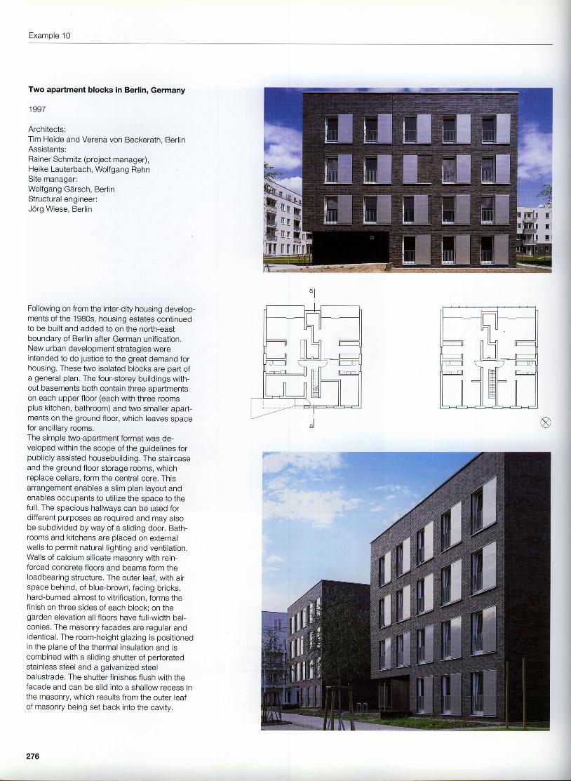
Two apartment blocks in Berlin, Germany
1997
Architects:Tim Heide and Verena von Beckerath, BerlinAssistants:Rainer Schmitz (project manager),Heike Lauterbach, Wolfgang RehnSite manager:Wolfgang Gdrsch, BerlinStructural engineer:Jdrg Wiese, Berlin
Following on from the inter-city housing develop-ments of the 1980s, housing estates continuedto be built and added to on the north-eastboundary of Berlin after German unification.New urban development strategies wereintended to do justice to the great demand forhousing. These two isolated blocks are part ofa general plan. The four-storey buildings with-out basements both contain three apartmentson each upper floor (each with three roomsplus kitchen, bathroom) and two smaller apart-ments on the ground floor, which leaves spacefor ancillary rooms.The simple two-apartment format was de-veloped within the scope of the guidelines forpublicly assisted housebuilding. The staircaseand the ground floor storage rooms, whichreplace cellars, form the central core. Thisarrangement enables a slim plan layout andenables occupants to utilize the space to thefull. The spacious hallways can be used fordifferent purposes as required and may alsobe subdivided by way of a sliding door. Bath-rooms and kitchens are placed on externalwalls to permit natural l ighting and ventilation.Walls of calcium silicate masonry with rein-forced concrete floors and beams form theloadbearing structure. The outer leaf, with airspace behind, of blue-brown, facing bricks,hard-burned almost to vitrification, forms thefinish on three sides of each block; on thegarden elevation all floors have full-width bal-conies. The masonry facades are regular andidentical. The room-height glazing is positionedin the plane of the thermal insulation and iscombined with a sliding shutter of perforatedstainless steel and a galvanized steelbalustrade. The shutter finishes flush with thefacade and can be slid into a shallow recess inthe masonry, which results from the outer leafof masonry being set back into the cavity.
276
Two aoadment blocks in Berlin
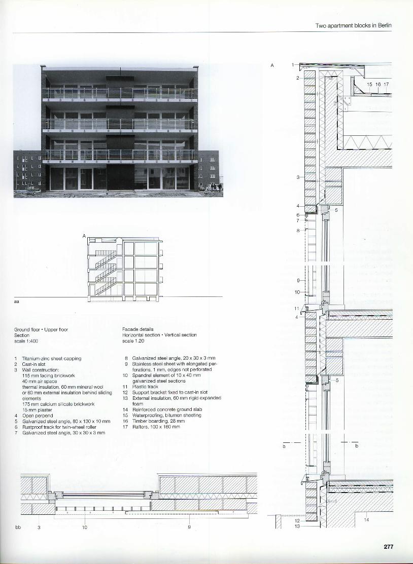
Ground floor Upper floorSectionscale 1:400
,l
3
Titanium-zinc sheet cappingCast-in slotWall construction:1 15 mm facing brickwork40 mm air spacethermal insulation, 60 mm mineral woolor 60 mm external insulation behind slidingelements175 mm calcium silicate brickwork15 mm plasterOpen perpendGalvanized steel angle, 80 x 130 x 10 mmRustproof track for twin-wheel rollerGalvanized steel angle, 30 x 30 x 3 mm
8 Galvanized steel angle, 20 x 30 x 3 mmI Stainless steel sheet with elongated per-
forations, 1 mm, edges not perforated10 Spandrel element of 10 x 40 mm
galvanized steel sections11 Plastic track1 2 Support bracket fixed to cast-in slot13 External insulation, 60 mm rigid expanded
foam14 Reinforced concrete ground slab15 Waterproofing, bitumen sheeting16 Timber boarding, 28 mm17 Rafters, 100 x 160 mm
4567
1 21 3
277
Example 'l 1
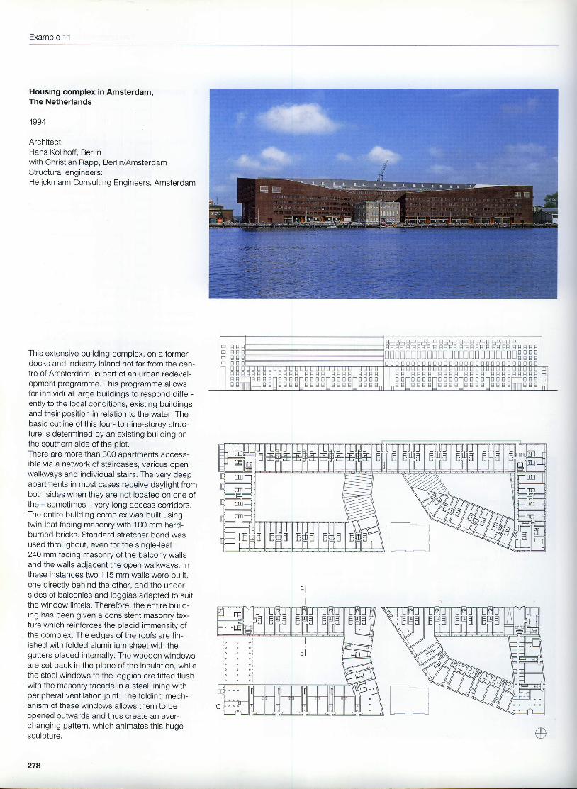
Housing complex in Amsterdam,The Netherlands
1994
Architect:Hans Kollhoff. Bedinwith Christian Rapp, Berlin/AmsterdamStructural engineers:Heijckmann Consulting Engineers, Amsterdam
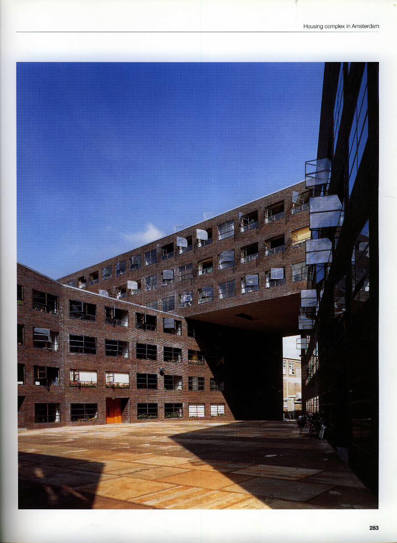
This extensive building complex, on a formerdocks and industry island not far from the cen-tre of Amsterdam, is part of an urban redevel-opment programme. This programme allowsfor individual large buildings to respond differ-ently to the local conditions, existing buildingsand their oosition in relation to the water. Thebasic outline of this four- to nine-storey struc-ture is determined by an existing building onthe southern side of the plot.There are more than 300 aoartments access-ible via a network of staircases, various openwalkways and individual stairs. The very deepapartments in most cases receive daylight fromboth sides when they are not located on one ofthe - sometimes - very long access corridors.The entire building complex was built usingtwin-leaf facing masonry with 100 mm hard-burned bricks. Standard stretcher bond wasused throughout, even for the single-leaf240 mm facing masonry of the balcony wallsand the walls adjacent the open walkways. Inthese instances two 1 15 mm walls were built,one directly behind the other, and the under-sides of balconies and loggias adapted to suitthe window lintels. Therefore, the entire build-ing has been given a consistent masonry tex-ture which reinforces the placid immensity ofthe complex. The edges of the roofs are fin-ished with folded aluminium sheet with thegutters placed internally. The wooden windowsare set back in the plane of the insulation, whilethe steel windows to the loggias are fitted flushwith the masonry facade in a steel lining withperipheral venti lation joint. The folding mech-anism of these windows allows them to beopened outwards and thus create an ever-changing pattern, which animates this hugesculoture.
278
BsBBEEsE
EEEEsB E S
E BS B
g E sB E BB E E
O E EB S SE E B
B E EE S EE S 8
E Es ss s
B E8 SB E
EililEilEHA ilEH3 ilEHtl
o
Housing complex in Amsterdam
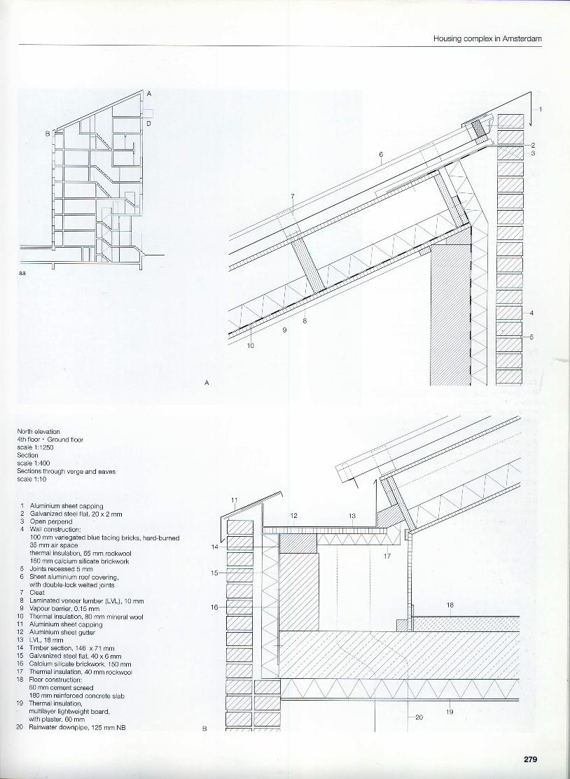
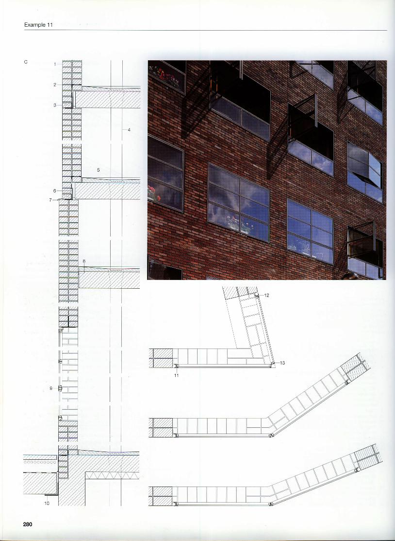
North elevation4th floor . Ground floorscale 1:1250Sectionscale 1:400Sections through verge and eavesscale 1 :10
1 Aluminium sheet capping2 Galvanized steel flat, 2O x 2 mm3 Open perpend4 Wall construction:
100 mm variegated blue facing bricks, hard-burned35 mm air soacethermal insulation, 65 mm rockwool150 mm calcium silicate bricl<work
with plaster, 60 mm20 Rainwater downpipe, 125 mm NB
279
Example 11
(ZAV'/'/)mmvvvTvw{4ntf'
i l l
iltr-i l -
l l l
l lr-- lfftrll l - -il ---t---'t
ll L_-l II LT
_ ]--ltrl
l l - -il T--t---
ll L--ll lllf
-__lH[ErzTzmmmmv7zv772
2AO
Housing complex in Amsterdam
Section through external wallHorizontal sections through corners of building with steelwindows: 76.58" - 144.92" - 158.38"Elevation on steel windowHorizontal section through steel windowscale 1:20
1 Wall construction:208 mm variegated blue facing bricks,hard-burned
2 Joints recessed 5 mm3 Open perpend4 Rainwater downpipe, 125 mm NB5 Floor construction:
cement screed laid to falls, coated180 mm reinforced concrete slabcut-out for drainage
4 mm toughened safety glass10 Steel angle, 1 50 x 1 50 x 15 mm, with slip joint11 Steel angle, 40 x 20 x 4 mm12 Steel channel , 40 x 20 x4 mm13 2 No . s t ee lang les , 40x20x4 mm
Example 11
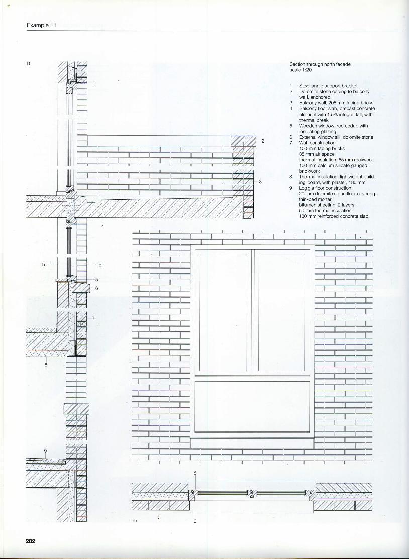
Section through north facadescale 1:20
1
o
t'
I
Steel angle support bracketDolomite stone coping to balconywall, anchoredBalcony wall, 208 mm facing bricksBalcony floor slab, precast concreteelement with 1 .57o integral fall, withthermal breakWooden window, red cedar, withinsulating glazingExternal window sill, dolomite stoneWall construction:100 mm facing bricks35 mm air spacethermal insulation. 65 mm rockwool100 mm calcium silicate gaugedbrickworkThermal insulation, lightweight build-ing board, with plaster, 180 mmLoggia floor construction:20 mm dolomite stone floor coveringthin-bed mortarbitumen sheeting, 2 layers50 mm thermal insulation180 mm reinforced concrete slab
282
Housing complex in Amsterdam
Example 12
Extension to Hirschberg Palace nearBeilngries, Germany
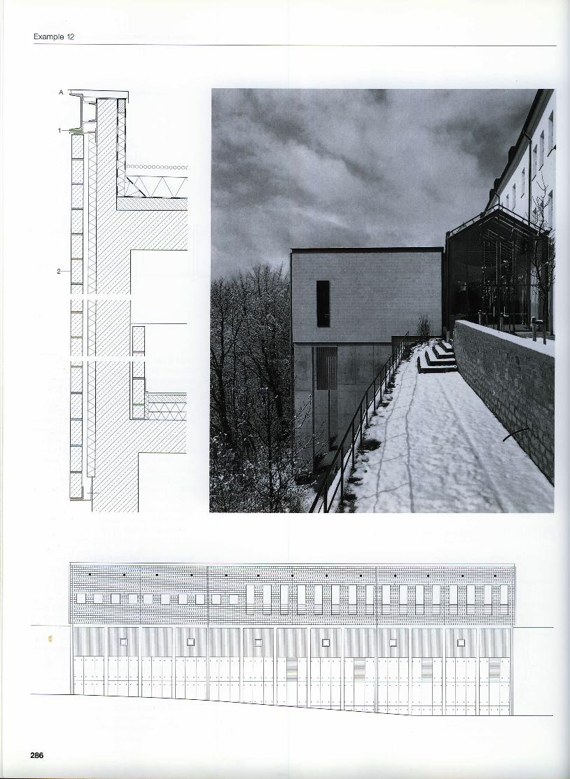
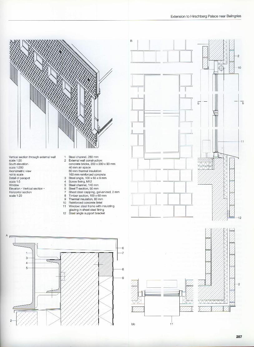
The symmetrical palace structure dating fromthe 18th century stands on a narrow hilltop andtherefore offered little scope for any extension.This completely refurbished building is used bythe church for spiritual exercises and educa-tion. Besides extensive conversion work, anew annex was built to accommodate kitchen,dining hall and storage facilities.The new section is positioned in front of thesouth wing of the palace and is partly built intothe side of the hill. A row of tall concretecolumns supports the long, slim structure clearof the slope and hence emphasizes the con-trast with the strictly uniform, rendered finish tothe palace. Fair-face concrete and concretebricks for the outer leaf of the partial-fill cavitywall underline the independence of the newstructure. A long, narrow, steel-and-glass hallprovides a clear demarcation between old andnew.The outer leaf is clearly distinguished from therest of the construction; there is an air soacebehind and therefore the leaf is oositioned40 mm proud of the reinforced concrete walland the row of columns. Grey steel anglesmark the corners of the facing brickwork, anda steel channel forms an elegant finish to thetop of the walls. The deeply recessed, narrow,vertical window slits are also framed in greysteel which projects beyond the facade and soconveys the impression of very precisely locat-ed cut-outs. The steel external stair employs aparticularly delicate construction in order not todisturb the careful balance between harmoniz-ation and indeoendence.All these clear, simple details lend the annex alightness and obvious language which is quitedistinct from that of the old palace,
2U
o
Extension to Hirschberg Palace near Beilngries
Location plan scale 1:2000Section scale 1:250Ground floorscale 1:500
Baroque entranceGlass hallKitchenDining hall
0 f l01 [ [ [ [ [ [ 0 [0 [0 [ [,t::'ffi 2
l l l l r l I
L26
Example 12
286
Extension to Hirschberg Palace near Beilngries
' -.L --lL,lL]TI[]TItl[]Flltrt:tr-l llrr
lrVertical section through e)dernal wallscale 1:20South elevationscale 1:250Axonometric viewnot to scaleDetail of parapetscale 1:5WindowElevation . Vertical section .
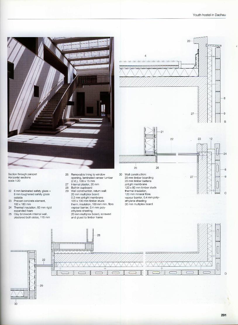
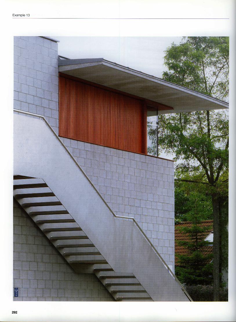
This facility, run by the German Youth HostelsAssociation, is more than just a youth hostel.Situated near the former Nazi concentrationand extermination camp, it acts as a centre forgetting to grips with the dark side of Germany'shistory. The architectural form is intended toreflect both the functions of the building butalso this special task. Apart from the mainbuilding, there is also a building for the staffand the separate "Raum der Stille" (Room ofSilence). These three structures frame a tran-quil inner courtyard - a garden and structuredspace, which is ideal for understanding andexperiencing the serious issues that dominatethis place. The restrained architectureresponds to its surroundings by limiting thematerials used to timber and facing brickrarorkof light-coloured concrete bricks. The textureof the building emphasizes the low-rise, elon-gated form; both in terms of the size and thestyle of the facade. The main building covers alarge area and so two storeys are adequate. ltmeasures 24.5 x60 m and is arranged as twoparallel blocks either side of a central circu-lation zone. The architectural setting distin-guishes between the different materials. Forinstance, on the west side of the building, thewooden recesses for windows and sunshadeson the ground floor are juxtaposed with theconcrete masonry lintels and spandrel panelsof the upper floor. Placing the masonry abovethe timber is a reversal of our customary ideasand introduces a different reality to challengethe perception of the observer. This is an artis-tic contrivance for reminding us of the specialimportance of this place. The wall constructionis conventional - paftial{ill cavity wall withouter leaf supported on individual brackets -but incorporates special details that emphasizeand preserve the restful uniformity of thestretcher bond. Such details include the mortarjoints raked out to a depth of 15 mm and themovement joints which zigzaglo follow thebond.
28
Youth hostel in Dachau
rlll [!ll
[--lIl i lfllI
Il i l
[l1i tl Ground floor
Upper floorSectionsscale 1:600
1 "Raum der Stille"2 Staff accommodation3 Hal l4 Dining room5 Seminar room6 Cafeteria7 Reception8 Management9 Library
289
Example 13
Io o o o o 6 0 0 0 0 0 0 0 0 0 0 0
4
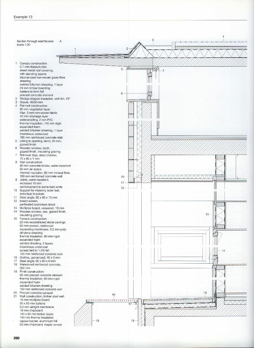
lrrlrrlrrrlrrlrrrrrrlrlrrlrlrrlrrlrrrlrrlrrrrlrrlrlrrlrrlrlrrlrrlrrlrlrrrlrrlrrlrlrrlSection through east facadescale 1:20
Canopy construction:0.7 mm titanium-zincsheet metal roof covering,with standing seams
4
bitumenized non-woven glass fibresheetingwelded bitumen sheeting, 1 layer24 mm timber boardingbattens to form fallorecast concrete elementWedge-shaped insulation, with foil, 45'Gravel, 40/50 mmFlat roof construction:80 mm vegetation layerfilter, 5 mm non-woven fabric40 mm drainage layerwaterproofing,2 mm PVCthermal insulation, 140 mm rigidexpanded foamwelded bitumen sheeting, 1 layerbituminous undercoat180 mm reinforced concrete slabLining to opening, larch, 20 mm,glazed finishWooden window, larch,glazed finish, insulating glazingRolFover stop, steel channel,7 0 x 6 0 x 1 m mWall construction:90 mm concrete bricks, water+epellent60 mm air soacethermal insulation, 80 mm mineral fibre160 mm reinforced concrete wallJoints, water-repellent,recessed 15 mmreinforcement to some bed joints p
20 mm reconstituted stone pavings60 mm screed, reinforcedseparating membrane, 0.2 mm poly-ethylene sheetingthermal insulation, 80 mm rigidexoanded foamwelded sheeting, 2 layersbituminous undercoatscreed laid to 1 .SVo fall120 mm reinforced concrete slabGrating, galvanized, 40 x 3 mmSteel angle, 60 x 60 x 8 mmWaterproof reinforced concrete,300 mmPlinth construction:60 mm orecast concrete elementthermal insulation, 60 mm rigidexoanded foamwelded bitumen sheeting150 mm reinforced concrete wallPrecast concrete parapetWall construction, timber stud wall:16 mm multiolex board30 x 50 mm battens0.2 mm airtight membrane19 mm chipboard140 x 60 mm timber studs140 mm thermal insulationvapour barrier, aluminium foil20 mm chipboard, maple veneer
1 0
1 1
1 61 71 8
1 9
2021
IL
290
Youth hostel in Dachau
2625
Section through parapetHorizontal sectionsscale 1:20
22 6mm laminated safety glass +I mm toughened safety glassoutside
23 Precast concrete element,150 x 180 mm
24 Thermal insulation, 60 mm rigidpvnendod fnam
25 Clay brickwork internal wa,.,plastered both sides, 1 15 mm
Removable lining to windowopening, laminated veneer lumber(LVL), 136 x 15 mmInternal plaster, 20 mmBuilt-in cupboardWall construction, return wall:20 mm multiplex board0.2 mm airtight membrane1 20 x 100 mm timber studstherm. insulation, 100 mm min. fibrevapour barrier, 0,4 mm poly-ethylene sheeting20 mm multiplex board, screwedand glued to timber frame
Wall construction:20 mm timber boarding20 mm timber battensairtight membrane120 x 80 mm timber studsthermal insulation,120 mm mineral fibrevapour barrier,0.4 mm poly-ethylene sheeting30 mm multiplex board
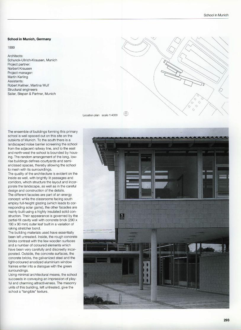
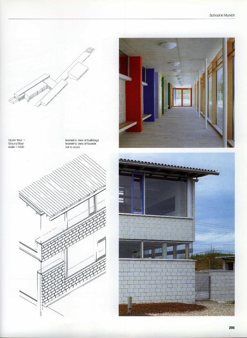
The ensemble of buildings forming this primaryschool is well soaced out on this site on theoutskirts of Munich, To the south there is alandscaped noise barrier screening the schoolfrom the adjacent railway line, and to the eastand north-west the school is bounded by hous-ing. The random arrangement of the long, low-rise buildings defines courtyards and semi-enclosed spaces, thereby allowing the schoolto mesh with its surroundings.The quality of the architecture is evident on theinside as well, with brightly lit passages andcorridors, which structure the layout and incor-porate the landscape, as well as in the carefuldesign and construction of the details.The difierent facades are part of an energyconcept: while the classrooms facing southemploy full-height glazing (which leads to cor-responding solar gains), the other facades aremainly built using a highly insulated solid con-struction. Their appearance is governed by thepartial{ill cavity wall with concrete brick (290 x190 x 90 mm) outer leaf buih in a variation ofraking stretcher bond.The building materials used have essentiallybeen left untreated. Inside, the rough concretebricks contrast with the few wooden surfacesand a number of coloured elements whichhave been very carefully and discreetly incor-porated. Outside, the concrete surfaces, theconcrete bricks, the galvanized steel and thelight-coloured anodized aluminium windowframes enter into a dialogue with the greensurroundings,Using minimal architectural means, the schoolsucceeds in conveying an impression of play-ful and charming attractiveness. The masonryunits of this building, left untreated, give theschool a "tangible" texture.
Location olan scale 1:4000
293
Example 14
2 l l t l l l 2 l l e l l ! 1 0
1 Indoor play area 6 WorkshoP2 Classroom 7 Sports hall3 After-school supervision I Void4 Multiouroose room 9 Staffroom5 Music room 10 Management
School in Munich
Upper floolGround floorscale 1 :1000
lsometric view of buildingslsometric view of facadenot to scale
295
Example 14
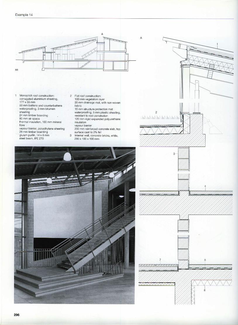
1 Monopitch roof construction:corrugated aluminium sheeting,177 x 55 mm50 mm battens and counterbattenswaterproofing, 3 mm bitumensheeting24 mm timber boarding80 mm air spacethermal insulation, 160 mm mineralfibrevapour barrier, polyethylene sheeting28 mm timber boardingglulam purlin, 14 x I mmsteel beam, IPE 270
Flat roof construction:100 mm vegetation layer20 mm drainage mat, with non-wovenfabric15 mm siructure orotection matwaterproofing, 5 mm plastic sheeting,resistant to root penetration120 mm rigid expanded polyurethaneinsulationvapour oarrrer200 mm reinforced concrete slab, topsudace cast to 2% fallInternal wall, concrete bricks, white,290 x 190 x 190 mm
296
School in Munich
Section through hallscale 1:400Section through clerestory over internal wallsection through external wallscale 1:20Section through classroom wingSection through sports hallscale 1:400
6
7
Floor construction:5 mm linoleum55 mm cement screed, reinforcedseparating membrane, polyethylenesheeting10 mm impact sound insulationDamp proof membrane on ground floorslab, 200 mm reinforced concrete slabThermal insulation, 100 mm rigidexpanded foamFloor construction:25 mm natural stone tiles laid in thinbed65 mm screedseparating membrane, polyethylenesheeting10 mm impact sound insulation200 mm reinforced concrete slab50 mm multiplex lightweight mineralbuilding board
8 Aluminium gutter9 Post-and-railfacade:
50 mm laminated veneer lumber (LVL),birch, clear lacquer to exposed faceinsulating glazing, aluminium coverprof ile, natural-colour anodized
10 Column, steel circular hollow section,82.5 dia. x 3.6 mm
outer leaf of concrete bricks, white,raking stretcher bond 290 x 1 90 x 9050 mm air spacethermal insulatron, 60 mm mineral wool240 mm reinforced concrete wall15 mm internal plasterOpen perpendPrecast concrete beam,300 x 90 x 2585 mmReinforced concrete corbel,210 x 250 x 250 mm
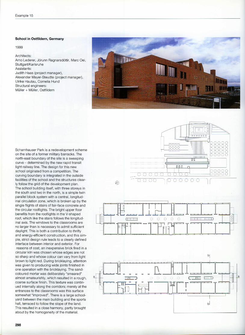
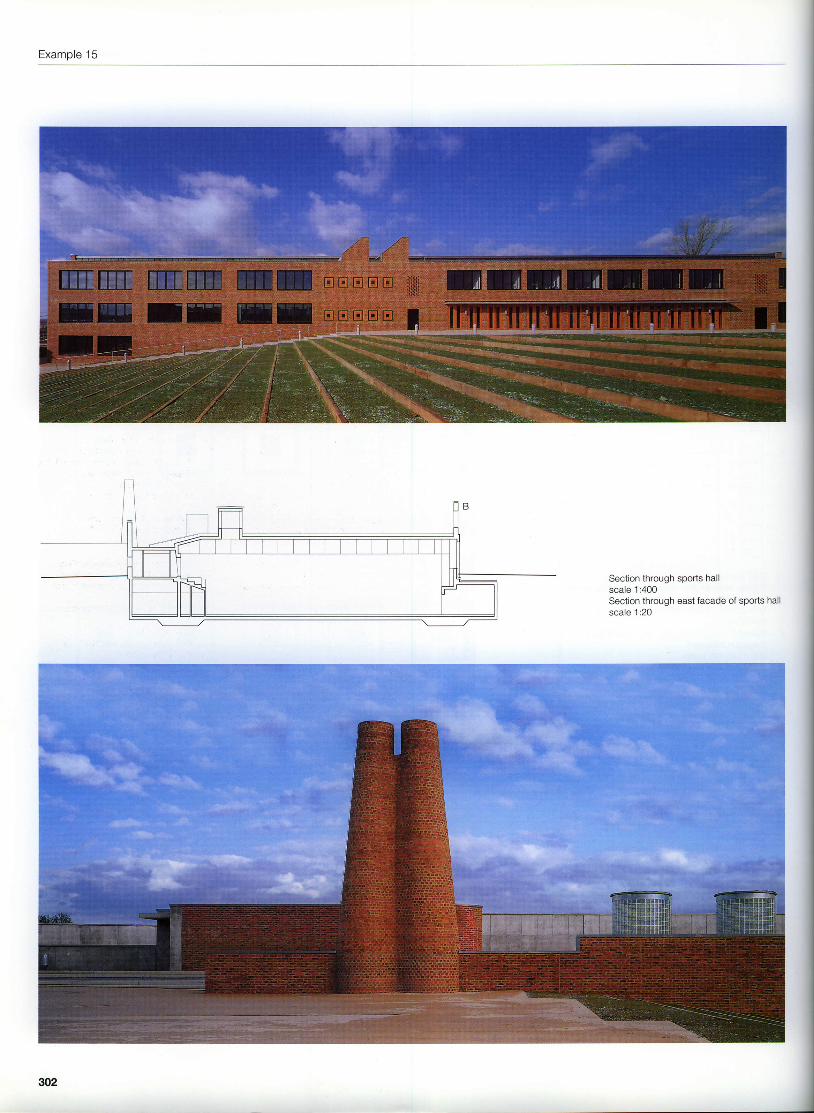
Scharnhauser Park is a redevelooment schemeon the site of a former military barracks. Thenorth-east boundary of the site is a sweepingcurve - determined by the new rapid transitl ight railway l ine. The design for this newschool originated from a competition. Thecurving boundary is integrated in the outsidefacilities of the school and the structures clear-ly follow the grid of the development plan.The school building itself, with three storeys inthe south and two in the north, is a simple twinparallel block system with a central, longitud-inal circulation zone, which is broken up by thesingle flights of stairs of fair-face concrete andthe circular rooflights. The bright upper floorbenefits from the rooflights in the V-shapedroof, which like the stairs follows the longitud-inal axis. The windows to the classrooms areno larger than is necessary to admit sufficientdaylight. This is both a contribution to thriftyand energy-efficient construction, and this sim-ple, strict design rule leads to a clearly definedinterface between interior and exterior. Forreasons of cost, an inexpensive brick fired in acircular kiln was chosen whose edges are notso sharp and whose colour can vary from lightbrown to l ight red. During bricklaying, attentionwas given to producing wide joints finished inone operation with the bricklaying. The sand-coloured moftar was deliberately "smeared"almost amateurishly, which resulted in a rough,coarse surface finish. This texture was contin-ued internally along the corridors; merely at theentrances to the classrooms was this surfacesomewhat "improved". There is a large school-yard between the main building and the sportshall, terraced to follow the slope of the land.This resulted in a close harmony, partly broughtabout by the homogeneity of the material.
298
@
'srp!
coooL t L r o oO C O L ]ooocO C C C
_)
ooooocoo
: _ : : '
School in Ostfildern
t l l l l mE Ero Etrtsrqr
n'- l t l lE mm boorstrmmmmnmmul mm
Location planscale 1:2500Upperfloor . Ground floorEast elevationSection through school buildingscale 1:800
299
Example 15
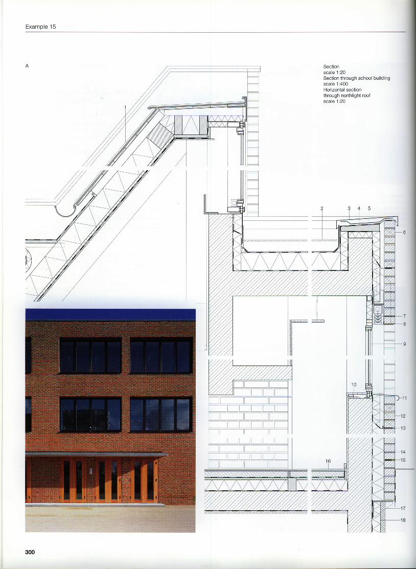
Sectionscale .1:20
Section through school buildingscale 1:400Horizontal sectionthrough northlight roofscale 1:20
300
School in Ostfildem
3456
d
I101 1
t z
Roof construction:0.7 mm titanium-zinc sheet, with standing seams24 mm timber boarding80 x 80 mm counterbattens (80 mm air spacebetween)2OO x 12O mm rafters (20O mm mineral fibreinsulation between)2OOx12O mm ourlin24-32 mm oriented strand board (OSB)vapour barrier,0.4 mm polyethylene sheeting12.5 mm plasterboardRoof construction:extensive planting,min. 120 mm vegetation layerprotection and storage matwaterproofing, bitumen sheeting, 2 layers, top layerresistant to root penetration190 mm thermal insulationvaoour barrier260 mm reinforced concrete slabParapet capping, 0.7 mm titanium-zinc sheetTimber sectionThermal insulation, 60 mm mineral fibreOpen perpendBlind, natural-colour aluminium, 50 mmBracket, stainless steel angleAluminium window with insulating glazingWindow sill, MDF board, lacqueredWindow sill, bent 3 mm aluminium sheet,front edge roundedWall construction:''| 15 mm clay facing brickwork45 mm air spacethermal insulation. 80 mm mineral fibre250 mm reinforced concrete wall15 mm internal DlasterMovement jointExternal insulation, 120 mmDamp proof courseParquet flooring, oak, 20 mmSupport bracket, stainless steel sheetExternal insulation, 80 mm
131 4
161 718
301
Example 15
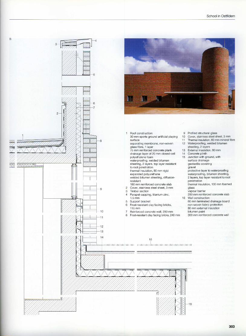
Section through sports hallscale 1:400Section through east facade of sports hallscale 1:20
so2
School in Ostfildern
234
56
78
Roof construction:30 mm sports ground artificial playingsurfaceseparating membrane, non-wovenglass fibre, 1 layer75 mm reinforced concrete plankdrainage layer of 20 mm closed-cellpolyethylene foamwaterproof ing, welded bitumensheeting, 2 layerc, top layer resistantto root penetrationthermal insulation, 80 mm rigidexpanded polyurethanewelded bitumen sheeting, diffusion-resistant180 mm reinforced concrete slabCover, stainless steel sheet, 3 mmTimber sectionParapet capping, titanium-zinc,1 .5 mmSupport bracketFrost-resistant clay facing bricks,' 115 mmReinforced concrete wall, 250 mmFrost-resistant clay facing bricks, 240 mm
9 Profiled structural glass1 0 Cover, stainless steel sheet, 3 mm11 Thermal insulation, 60 mm mineral fibre12 Waterproofing, welded bitumen
sheeting, 2 layers13 E)dernal insulation, 60 mm14 Concrete plinth15 Junction with ground, with
surface drainagegeotextile coveringgravelprotective layer to waterproofingwaterproof ing, bitumen sheeting,2 layers, top layer resistant to rootpenetrationthermal insulation, 100 mm foamedgrassvapour barrier250 mm reinforced concrete slab
16 Wall construction:60 mm laminated drainage boardnon-woven fabric protection80 mm external insulationbitumen paint300 mm reinforced concrete wall
l t cI
l r r r l i r l r r r r l l r r l l l t r t t r l t r l l r l t l r r l
ooooooooooooooooooooooooooooooooooooooo
303
Example 16
Town hall in Fellbach, Germany
1 987
Architect:Ernst Gisel, ZurichAssistants:Othmar Brugger, Heinrich Gerster,Harry Moor, Heinz Schmid, Leo SchweitzerSite manager:Peter Zimmermann, FilderstadtStructural engineer:Heinrich Bechert, Fellbach
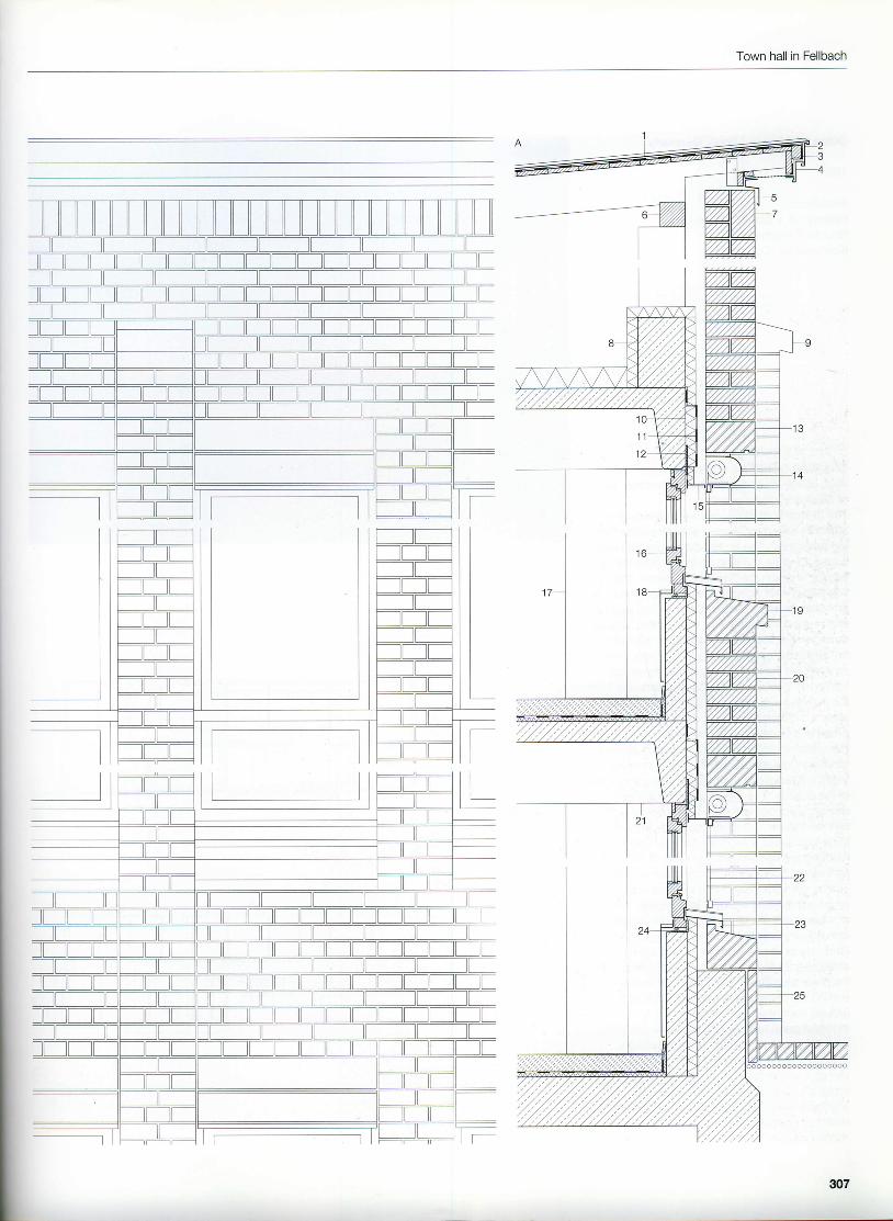
"Architecture that creates the town." Ernst Gisel'swork in Fellbach could be viewed in this l ight.The prosperous town of Fellbach with its fast-growing population and the usual outgrowthsof the 1950s and 1960s, also not unknown inother towns, was looking for a nucleus. Thearea around the Lutheran church, once shield-ed by a fortified wall, provided an adequatesetting for the 1979 competition to redesign thecentre of the town. The brief was to "create,together with a marketplace, not only a centrefor the local authority but also a lively zonewhich would be frequented by the citizens".The jury chose Gisel's design because of its"agreeable matter-of-factness". Well struc-tured, clearly arranged, decisive in its lan-guage, Ernst Gisel's solution makes excellentuse of both the internal and external spaces ofthis urban node, clarifying and structuring theouter contours. The configuration of the innercourtyards with their small alleyways and thesquare in front of the town hall themselves pro-vide a high urban quality.It seemed a natural choice to opt for a twin-leafmasonry construction with a 240 mm load-bearing outer leaf. However, the thickness ofthe thermal insulation used would these daysno longer satisfy the statutory requirements.The building exploits the advantages of a self-supporting masonry wall to the full: lesenes,corbels and columns in real masonry bond,robust detailing at the window reveals, plusmasonry stairs and semicircular arches.The masonry is complemented by naturalstone for the window sills and lintels as well asfor the clearly differentiated plinth.Designed in an age of f lourishing post-modernism, the architect has created an authen-tic setting without superfluous comments which,owing to its internal and external spatial quali-ties, its correct use of the materials and atten-tion to detail, has lost nothing of its topicality.
1 Cold deck roof construction, 5.4" pitch:copper sheet roof covering, 670 x 0.7 mm,double-lock welted jointsroofing felt24 mm timber boarding160 x 80 mm raftersair spacethermal insulation, .100 mm mineral woolreinforced concrete waffle slab,with white cement
2 Trim,0.7 mm copper sheet3 Closure strip, 60 x 40 mm4 Lower trim, 0.7 mm copper sheet on
bui ld ing paper5 Flashing, 0.7 mmcoppersheet6 Wall plate, '1 20 x 120 mm7 Soldier course, NF facing bricksI Reinforced concrete upstand beam9 Stone coping to lesene, Lodrino gneiss
10 Thermal insulation, 50 mm mineral fibre11 Damp proof membrane12 Fixing plate, galvanized steel, 140 x 5 mm13 Stone lintel, Lodrino gneiss1 4 Box for sunshade, 1 .5 mm copper sheet15 Cavity closer as inspection flap, 1 .5 mm copper
sheet, fixed with stainless steel screws in sleevesWooden window, with insulating glazingColumn, 300 mm dia.Water channelStone window sill, Lodrino gneissWall construction:240 mm yellow facing bricks in English bond42 mm air spacethermal insulation, 50 mm mineral fibre100 mm in-situ concrete spandrel panelsteel sheet cladding to spandrel panelWaffle slab, reinforced concrete,with white cementGuide cable for sunshadeWindow sill, 1.5 mm copper sheetSteel angle, 55 x 75 x 5 mm, galvanizedCladding to plinth, Maggia granite, exposedsurfaces knapped, 50 mm
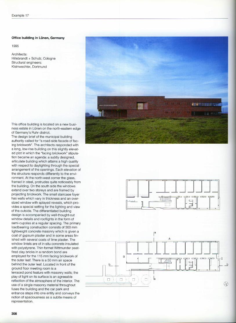
This office building is located on a new busi-ness estate in L0nen on the north-eastern edgeof Germany's Ruhr district.The design brief of the municipal buildingauthority called for "a road-side facade of fac-ing brickwork". The architects responded witha long, low-rise building on this slightly elevat-ed plot in which the "facing brickwork" stipula-tion became an agenda: a subtly designed,articulate building which attains a high qualitywith respect to daylighting through the specialarrangement of the openings. Each elevation ofthe structure responds differently to the envi-ronment. At the north-west corner the glass,framed in steel, protrudes quite noticeably fromthe building. On the south side the windowsextend over two storeys and are framed byprojecting brickwork. The small staircase foyerhas walls which vary in thickness and an over-sized window with splayed reveals, which pro-vides a special setting for the l ighting and viewof the outside. The differentiated buildingdesign is accompanied by wellthought-outwindow details and rooflights in the form ofsemi-cupolas at a regular spacing. The primaryloadbearing construction consists of 300 mmlightweight concrete masonry which is given acoat of gypsum plaster and in some areas fin-ished with several coats of lime plaster. Thewindow lintels are of in-situ concrete insulatedwith polystyrene. Thin-format Wittmunder peat-fired clay bricks in a random bond areemployed for the 1 15 mm facing brickwork ofthe outer leaf. There is a 50 mm air spacebehind the outer leaf , Located in front of theground floor meeting room is aterraced pond feature with masonry walls; theplay of l ight on its surface is an agreeablereflection of the atmosphere of the interior. Theuse of a single masonry material throughoutfuses the building and the car park andentrance steps into one entity and conveys thenotion of spaciousness as a subtle means ofranraeant4f i6n
308
Office building in Ltinen
1st floor . Ground floorscale 1:50OSectionsscale 1:250Section through south facadescale 1:20
1 Masonry frame in trass cement2 S tee lang le , ' | 50x150x12mm
3 Steel window, with insulatingglazing
4 Panel construction:15 mm cement rendering,flush with window, paintedthermal insulation, multiplexlightweight board, 50 mm
5 Wall construction:facing bricks, Wittmunderpeat-fired clay DF, 115 mm50 mm air space300 mm lightweight concretemasonry, with skim plaster coat
309
Example 17
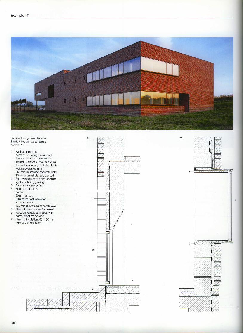
Section through east facadeSection through west facadescale 1:20
1 Wall construction:cement rendering, reinforced,finished with several coats ofsmooth, coloured lime renderingthermal insulation, multiplex light-weight board, 50 mm250 mm reinforced concrete lintel15 mm internal plaster, painted
2 Steel window, with tilting openingl lght , insulat ing glazingBitumen waterproofingFloor conslruction:carpet60 mm screed80 mm lhermal insulationvapour barner160 mm reinforced concrete slabSteel window in steel flat revealWooden reveal, laminated withdamp proof membraneThermal insulation, 50 + 30 mmrigid expanded foam
34
56
7
310
Computer centre in Karlsruhe
Computer centre in Karlsruhe, Germany
1 992
Architect:Heinz Mohl, KarlsruheProject manager:Peter LitzlbauerAssistants:M. Bertram, K. Bohm, H. Ddbbeling, G. Doring,N. Fostiropolous, S. Hirschfeld, R. Preisser,S. Ozcam, J. Schneider, M. Wagner, l. Walser,T. WeilerSite management:Stieff + Trunzler, KarlsruheStructural engineers:Ingenieurgruppe Bauen, Karlsruhe
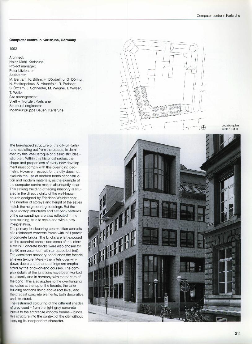
The fan-shaped structure of the city of Karls-ruhe, radiating out from the palace, is domin-ated by this late-Baroque or classicistic ideal-istic plan. Within this historical radius, theshape a'nd proportions of every new develop-ment must comply with this overriding geo-metry. However, respect for the city does notexclude the use of modern forms of construc-tion and modern materials, as the example ofthe computer centre makes abundantly clear.This striking building of facing masonry is situ-ated in the direct vicinity of the well-knownchurch designed by Friedrich Weinbrenner.The number of storeys and height ofthe eavesmatch the neighbouring buildings. But thelarge rooftop structures and set-back featuresof the surroundings are also reflected in thenew building, true to scale and with a newinterpretation.The primary loadbearing construction consistsof a reinforced concrete frame with infill panelsof concrete bricks. The bricks are left exposedon the spandrel panels and some of the intern-al walls. Concrete bricks were also chosen forthe 90 mm outer leaf (with air space behind).The consistent masonry bond lends the facadean even te)dure. Merely the lintels over win-dows, doors and other openings are empha-sized by the brick-on-end courses. The com-plex details at the junctions have been workedout exactly and in harmony with the pattern ofthe bond. This also applies to the overhangingcanopies at the top of the facade, the tallerbuilding sections rising above roof level, andthe precast concrete elements, both decorativeand structural.The restrained colouring of the different shadesof grey used - from the light grey concretebricks to the anthracite window frames - bindsthis structure into the context of the city withoutdenying its independent character.
ILocation planscale 1:2000
"o.*..-li;;f'l.ortl*;!11lg|m
311
Example 18
Section through facadescale 1:100lsomelric view of eaves cornicenot to scale
IILIII
Comouter centre in Kadsruhe
Section through facadescale 1:20
23
4
5
o7I
Concrete bricks, white,2 9 0 x 1 9 0 x 9 0 m mPrecast concrete elementRainwater hopper,with overflowInsulating glazing on steelirameworkStainless steel wall tie withinsulation clip and drip discConcrete brick lintel, 90 mmSupport bracket, steel angleAluminium window, colour-coated, with insulating glazingWall construction:concrete bricks, white,290 x 190 x 90 mm50 mm air spacethermal insulation,60 mm mineral fibre240 mm concrete bricks asinfill panels in reinforcedconcrete frameOpen perpendDamp proof course, bitumensheeting on stainless steelsheet as supportWaterproofing, bitumensheeting, 2 layersRigid thermal insulationLoadbearing reinforcedconcrete structure
313
Example 19
Mixed-use building in Zlirich, Switzerland
1993
Architects:Haessig + Partner, ZurichFelix B. Haessig, Peter C. Haessig,Bruno ClausenStructural engineers:Schubiger AG, Zurich
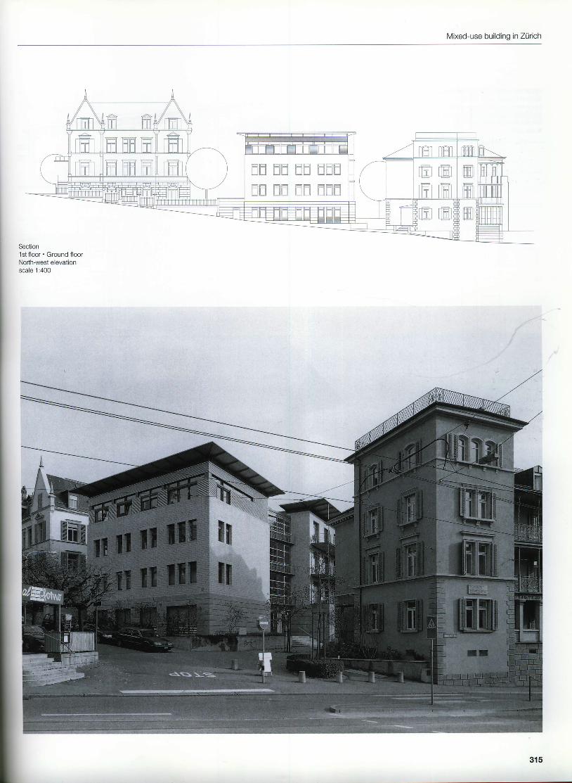
The north-west boundary of the grounds toZurich Hospital is denoted by a loosely spac'edrow of buildings. One of the gaps was filledwith two new structures positioned at a slightangle to each other, one with apartments, theother with laboratories, joined by a glazedaccess block. The geometry and alignment ofboth buildings follow the existing lines of thesurrounding buildings. The architectural lan-guage of the two components is related butvaried slightly to reflect the different functions.In terms of volume and scale they echo theregular urban structure of the existing buildingstock. Like the neighbouring structures, thereis a plinth which can adapt to the existingtopography. Clad in granite slabs, the plinthforms a common foundation to the two build-ings; likewise, the large overhanging eavescreate a common termination to the walls. Toestablish a difference, the western uppermoststory is set back and provided with a claddingof corrugated aluminium sheeting. The remain-ing facades are, in the main, of calcium silicatebricks, 120 mm thick, built in stretcher bond.There is an air space and 100 mm of thermalinsulation between the facing briclarork of theouter leaf and the reinforced concrete load-bearing structure. Window lintels, mullions andsills comprise precast concrete elements cladin 30 mm thick calcium sil icate brick slios. Allthe masonry is pointed throughout with a greycement mortar, even at the junctions betweenthe prefabricated and in-situ walls, to createthe impression of a seamless masonry struc-ture. The interior of the building also employsprefabricated facing masonry erected with thesame precision as the elterior.
314
Mixed-use building in Zurich
d d E E E E E E F
EE EtEt EU lltElLll
|fil[-t fI fl ti] t-l llt--t lftt . l ! | L l r t L L r l u u u u u
Horizontal section through windowsSection through west facadeHorizontal section through plinth at entranceHorizontal section through standard storey at entranceSection through staircase wallscale 1:20
i..1\
Aluminium window,micacious iron oxidefinish, with insulatingglazingWindow sill, calciumsilicate elementReinforced concretemul l ion wi th calc iumsilicate claddingWall construction:120 mm calcium silicatebricks40 mm air spacethermal insulation,100 mm mineral woolSteel angle,100 x 30 x 3.5 mmCanopy construction:titanium-zinc sheet roofcovering, 0.7 mm, withdouble-lock weltedjointsroofing felt100 x 40 mm timberboarding screwed to finSteel angle,3 0 x 3 0 x 4 m mCorrugated aluminiumsheeting, mlll-finished,18 x 76 mmRoof construction:steel beam, IPE 240thermal insulation,140 mm mineral woolvoidvapour Darner18 mm plasterboard
10 Sunshade, fabric blind11 Reinforced concrete
lintel with calciumsilicate cladding
12 Steel angle,1 2 0 x 6 0 x 1 2 m m
13 Stainless steel bracket
316
Mixed-use building in Zurich
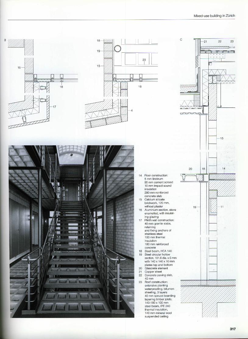
1 4 Floor construction:5 mm linoleum95 mm cement screed10 mm impact soundinsulation280 mm reinforcedconcrete slabCalcium silicatebrict<work, 120 mm,without plasterAluminium section, stoveenamelled, with insulat-ing glazingPlinth wall construction:40 mm granite slabs,retainingand fixing anchors ofstainless steel'100 mm thermalinsulation180 mm reinforcedconcrereSteel beam, HEA 140Steel circular hollowsection, 101.6 dia. x5 mmwith 140 x 140 x 10 mmplates top and bottomGlascrete elementCopper sheetConcrete paving slab,40 mmRoof construction:extensive plantingwaterproofing, bitumensheeting, 3 layers40 mm spruce boardingtapering timber joists,140-180 x 100 mmsteel beam, IPE 240thermal insulation,140 mm mineral woolsuspended ceiling
l c
1 6
1 7
1 81 9
2021
23
317
Example 20
Mixed-use development in Berlin, Germany
1996
Architects:Petra and Paul Kahlfeldt, BerlinAssistants:Anja Herold, Christoph Haag,Yves Minssarl, Michael Fuchs,Jorn Potting, Thomas Kii lber, Conor Moran,Frauke Hellweg, Martin OestlundStructural engineers:Ingenieurburo Fink, Ber l in
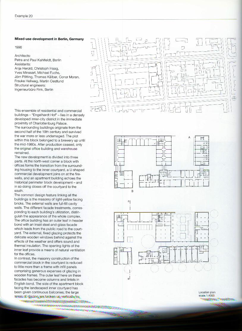
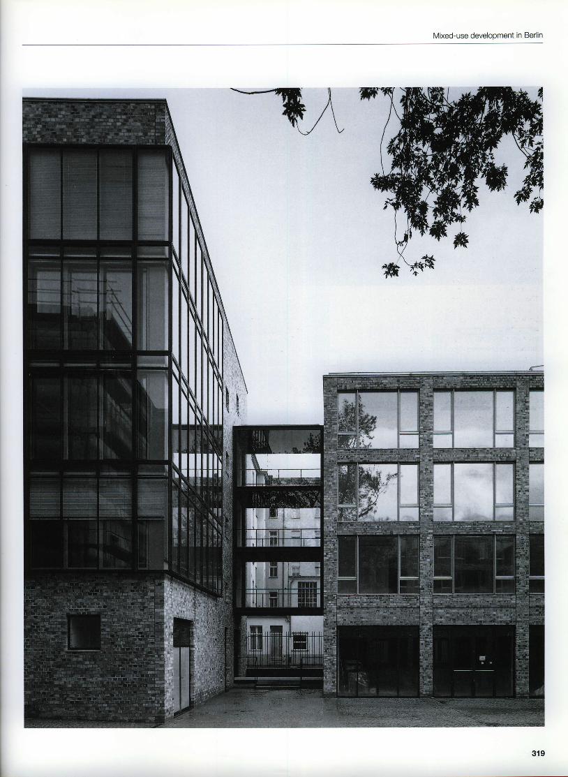
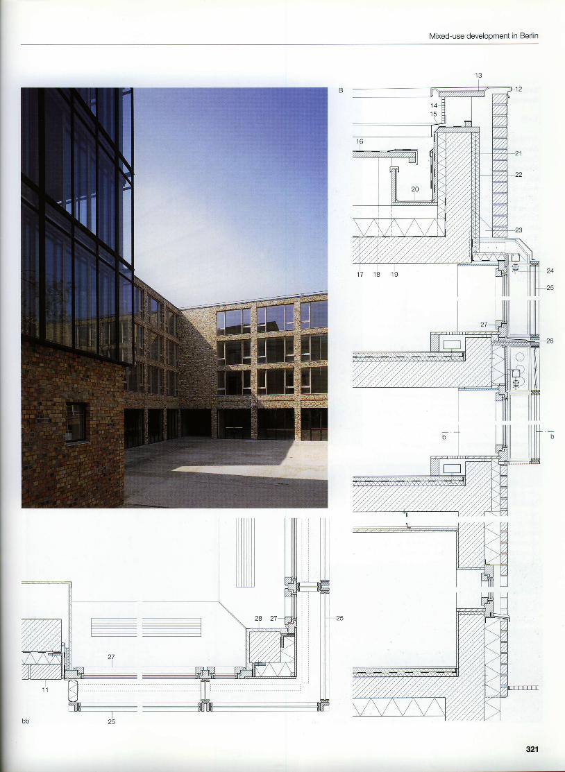
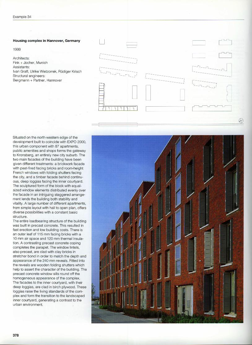
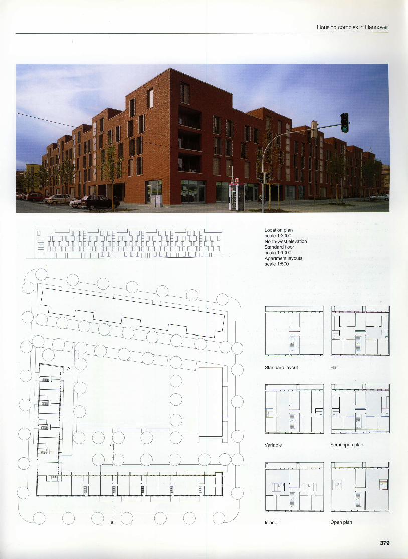
This ensemble of residential and commercialbuildings - "Engelhardt Hof" - l ies in a denselydeveloped inner-city district in the immediateproximity of Charlottenburg Palace.The surrounding buildings originate from thesecond half of the 19th century and survivedthe war more or less undamaged. The plotwithin this block belonged to a brewery up unti lthe mid-1980s. After production ceased, onlythe original office building and warehouseremained.The new development is divided into threeparts. At the north-west corner a block withoffices forms the transition from the surround-ing housing to the inner courtyard, a U-shapedcommercial development joins on at the fire-walls, and an apartment building echoes thehistorical perimeter block development - andin so doing closes off the courtyard to thesouth.The common design feature l inking all thebuildings is the masonry of l ight-yellow facingbricks. The external walls are full-f i l l cavitywalls. The different facade treatments, corres-ponding to each building's uti l ization, distin-guish the appearance of the whole complex.The ofi ice building has an outer leaf in headerbond with an inset steel-and-glass facadewhich leads from the public road to the court-yard. The external, f ixed glazing protects thedelicate wooden windows behind against theeffects of the weather and offers sound andthermal insulation. The opening l ights of theinner leaf provide a means of natural venti lationfor the offices.ln contrast, the masonry construction of thecommercial block in the courtyard is reducedto l itt le more than a frame with infi l l panelscomprisrng generous expanses of glazing inwooden frames. The outer leaf here on thesefacades has become columns and lintels inEnglish bond. The side of the apartment blockfacing the landscaped inner courtyard hasbeen given continuous balconies: the largea\eas al q\aZtnqare \xoken uq ver\\ca\\n\1
:\\\\\=\\\::-\\:1.:.-:S:::l::l{'-=.=:
LI
i t -
f -1\ -
-:-i i -i i
i ri l
I
]"r \I * r
f ' 1 ii t \ 1
i-i
il- t
1 iI t - l l l J 1 lt i l i i L l i l . l
- : - f f i - - E F = -r|-' LT-- -1 I I lL LIL --lL '.1! --ll-
Effin iliTr-lpild pl flflE L -l ll r: t ir+]t tH!l'.X' ll',X, 'l'
I^ l
Location planscale 1:4000"':-::\ir\---:s.::\lr:l
Mixed-use development in Berlin
Example 20
mF!tfrm- - - - L n - -
tI-!mmF!- - - - - - - -mmrumm
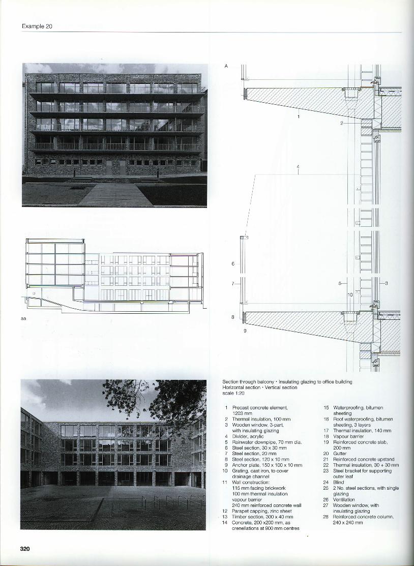
Precast concrete element,1203 mmThermal insulation, 100 mmWooden window, 3-part,with insulating glazingDivider, acrylicRainwater downpipe, 70 mm dia.Steel section, 30 x 30 mmSteel section, 20 mmSteel section, 120 x 10 mmAnchor plate, 150 x 100 x 10 mmGrating, cast iron, to coverdrainage channelWall construction:115 mm facing brickwork100 mm thermal insulationvapour barrier240 mm reinforced concrete wall
12 Parapetcapping, z incsheet13 Timber section, 300 x 40 mm14 Concrete. 200x200mm. as
20 GutterReinforced concrete upstandThermal insulation, 30 + 30 mmSteel bracket for supportingouter leafBlind2 No. steel sections, with singleglazingVentilationWooden window, withinsulating glazingReinforced concrete column,24O x24O mm
J
ffif.lllll
Section through balcony . Insulating glazing to office buildingHorizontal section . Vertical sectionscale 1:20
23
45o78I
1 0
t c
1 6
1 71 81 9
1 l
212223
2425
2627
28
320
Mixed-use develooment in Berlin
321
Example 21
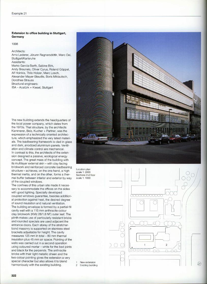
Extension to office building in Stuttgart,Germany
1 998
Architects:Arno Lederer, J6runn Ragnarsd6ttir, Marc Oei,StuttgarVKarlsruheAssistants:Marko Garcia-Barth, Sabine Birk,Andy Brauneis, Oliver Cyrus, Roland Goppel,Alf Hoinkis, Thilo Holzer, Marc Losch,Alexander Mayer-Steudte, Boris Miklautsch,Dorothee StraussStructural engineers:IBA - Acaturk + Kiesel, Stuttgart
The new building e)dends the headquarters ofthe local power company, which dates fromthe '1970s. That structure, by the architectsKammerer, Belz, Kucher + Partner, was theexpression of a technically oriented architec-ture, which emphasized the very latest materi-als. The loadbearing framework is clad in glassand dark, anodized aluminium panels. Ventil-ation and climate control are mechanical.ln contrast to this, the architects of the exten-sion designed a passive, ecological energyconcept. The great mass of the building withits multilayer external skin - with clay facingbrickwork and reinforced concrete loadbearingstructure - achieves, on the one hand, a highthermal inertia, and on the other, forms a ther-mal buffer between interior and exterior by wayof the coupled windows.The confines of this urban site made it neces-sary to accommodate the offices on the sideswith good lighting. Specially developedcoupled windows guarantee, besides addition-al protection against heat, the desired degreeof sound insulation and natural ventilation.The building envelope is formed by a partial{i l lcavity wall with a 115 mm anthracite-colourclay brickwork (KMz28/1.8 NF) outer leaf, Theplinth makes use of particularly resistant bricksand rounded specials are used adjacent theentrance doors. Each storey of the stretcher-bond masonry is supported on stainless steelbrackets adjustable for height. The cavitymeasures 125 mm in total - B0 mm thermalinsulation plus 45 mm air space. Pointing of thewalls was carried out in a second operationusing coloured mortar - white for the bed jointsand black for the perpends. The anthracitebricks with their l ight metall ic sheen and thetwo-colour pointing gives the extension a veryspecial character but also allows it to blendharmoniously with the existing building.
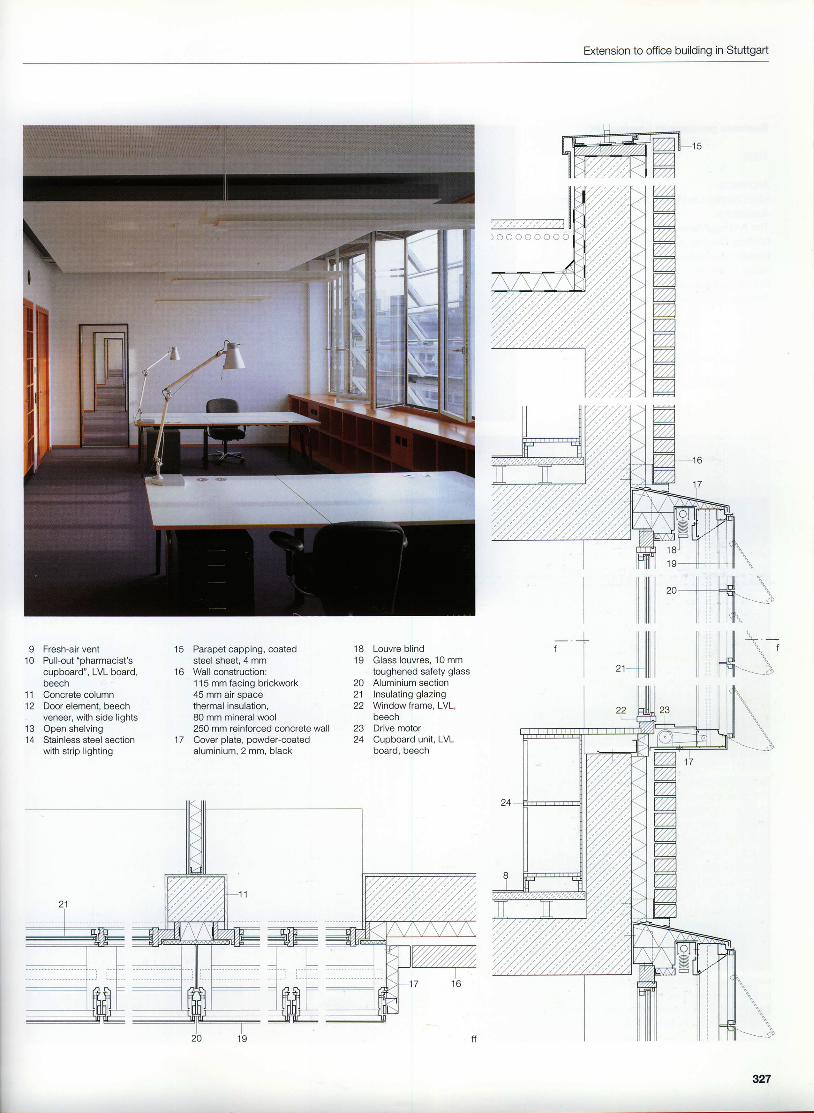
Section through restaurantscale 1: 100Entrance lobbyVertical sectionHorizontal sectionscale 1:50
1 Barrel-vault roof construction (withextensive planting):200 mm vegetation and drainage layernon-woven fabric as protection andfilterprotective mat, granulated rubberwaterproofing, 2 layersthermal insulation, 100 mm foamed glasswaterproof sheeting as temporary roofcovering150 mm lean-mix concrete240 mm clay brickwork
2 Loadbearing column, 490 x 490 mmfacing brickwork
Lighting units forming top of lobby:2 panes of glass, sand-blastedfluorescent tubesSteel angle as support to outer leafof facing brickworkCanopy with drainage channel,in-situ reinforced concreteWall construction:115 mm facing brickwork45 mm air spacethermal insulation, 80 mm mineral wool250 mm reinforced concrete wall15 mm internal plasterFloor construction:mat in matwell (non-slip steel traywith drainage)60 mm thermal insulation250 mm reinforced concrete slab300 mm reinforced concrete wallLobby element:doors in steel framedoor leaves of steel with woodenplanks and glass elements
II
325
Example 21
Section through corridoradjacent officesHorizontal section through alcovein ofiiceSectjon through facadeHorizontal section throughcoupled windowscale 1:20
Fresh-air ventPull-out "pharmacist'scupboard', LVL board,beechConcrete columnDoor element, beechveneer, with side lightsOpen shelvingStainless steel sectionwith strip lighting
Parapet capping, coatedsteel sheet. 4 mmWall construction:115 mm facing briclovork45 mm air sDacethermal insulation,80 mm mineral wool250 mm reinforced concrete wallCover plate, powder-coatedaluminium,2 mm, black
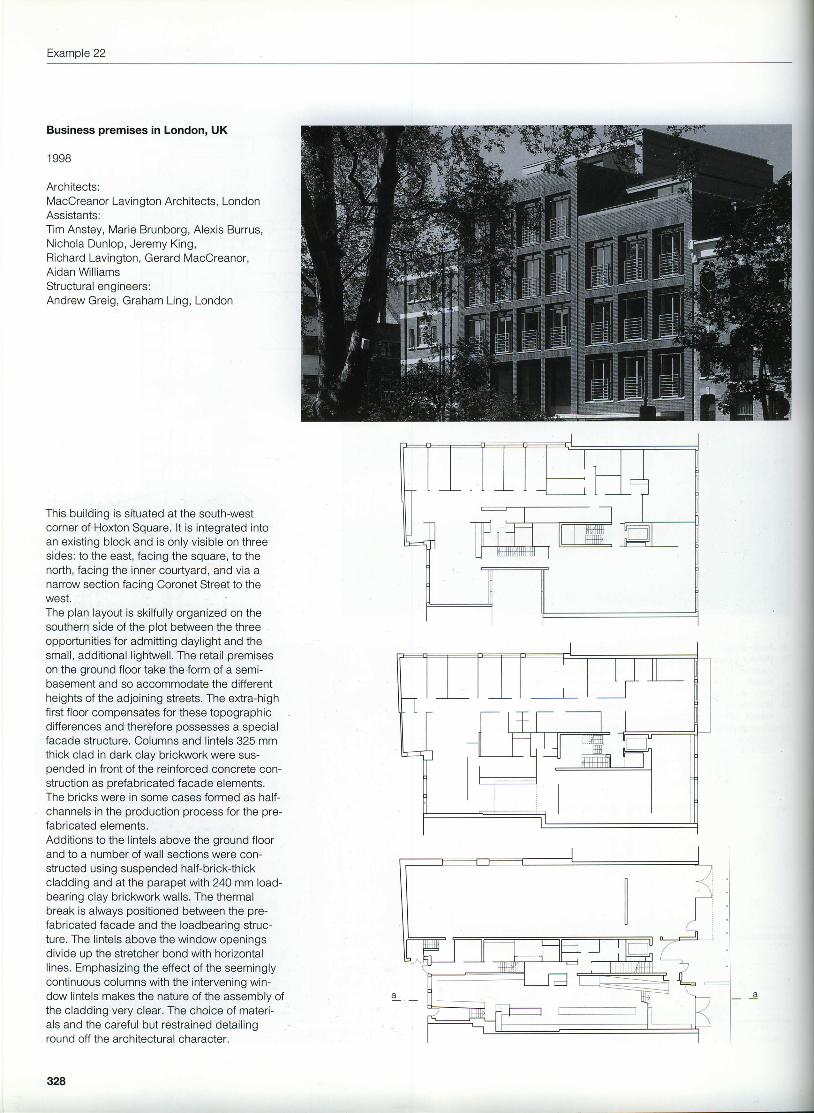
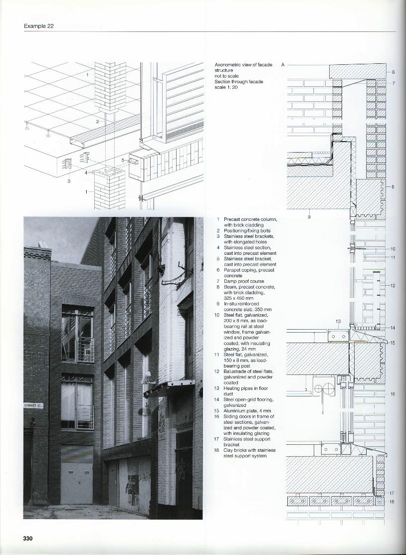
Architects:MacOreanor Lavington Architects, LondonAssistants:Tim Anstey, Marie Brunborg, Alexis Burrus,Nichola Dunlop, Jeremy King,Richard Lavington, Gerard MacCreanor,Aidan Will iamsStructural engineers:Andrew Greig, Graham Ling, London
This building is situated at the south-westcorner of Hoxton Square. lt is integrated intoan existing block and is only visible on threesides: to the east, facing the square, to thenorth, facing the inner courtyard, and via anarrow section facing Coronet Street to theWESI.
The plan layout is skilfully organized on thesouthern side of the olot between the threeopportunities for admitting daylight and thesmall, additional l ightwell. The retail premiseson the ground floor take the form of a semi-basement and so accommodate the differentheights of the adjoining streets. The extra-highfirst floor compensates for these topographicdifferences and therefore possesses a specialfacade structure. Columns and lintels 325 mmthick clad in dark clay brickwork were sus-pended in front ofthe reinforced concrete con-struction as orefabricated facade elements.The bricks were in some cases formed as half-channels in the production process for the pre-fabricated elements.Additions to the lintels above the ground floorand to a number of wall sections were con-structed using suspended half-brick-thickcladding and at the parapet with 240 mm load-bearing clay brickwork walls. The thermalbreak is always positioned between the pre-fabricated facade and the loadbearing struc-ture. The lintels above the window openingsdivide up the stretcher bond with horizontallines. Emphasizing the effect of the seeminglycontinuous columns with the intervening win-dow lintels makes the nature of the assembly ofthe cladding very clear. The choice of materi-als and the careful but restrained detailinground off the architectural character.
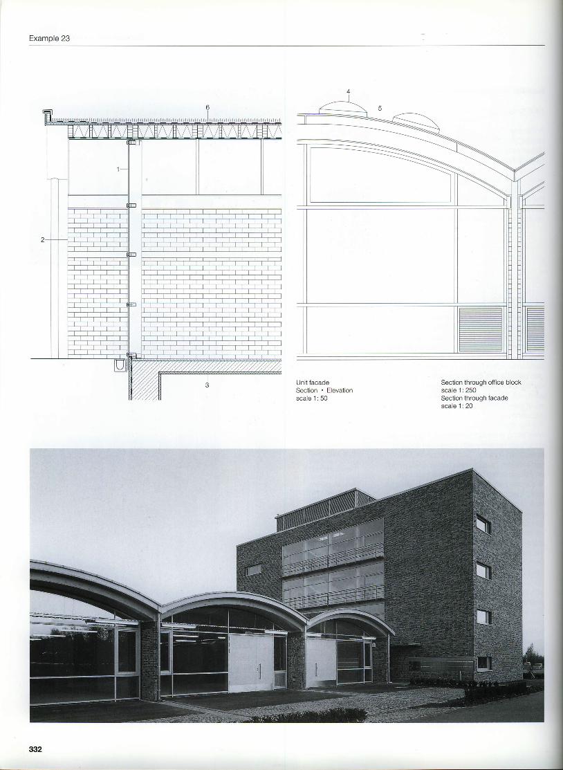
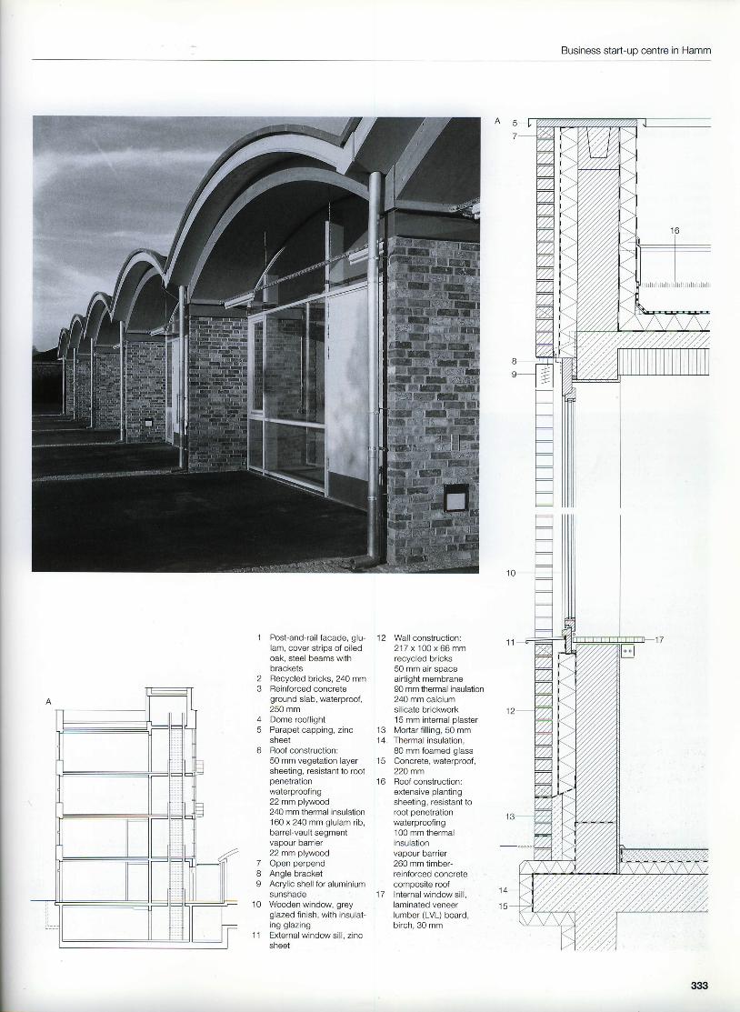
This business start-uo centre was built on oneof the countless former industrial sites thattoday are being put to new uses. The aim ofthis project was to provide assistance for eco-logically oriented manual trades and servicecompanies in the building industry. The com-plex consists of a four-storey office block and anumber of two-storey units grouped around acourtyard. These units can be divided in a vari-ety of ways and so can accommodate up to24 businesses.The four-storey office block, with circulationzone along one side, consists of 240 mm calci-um silicate masonry with composite floors ofboards laid on edge cast in concrete. Thepartial{ill cavity walls were constructed usingrecycled bricks from demolished buildings.The lintels were formed from bricks in stretcherbond supported on a steel angle in order tohighlight the rows of windows. These areplaced in the plane of the thermal insulation.Junctions with partitions are characterized by acladding of wooden panels. The sunshadesare clearly visible beneath the lintels in front ofthe windows,The units are based on a steel framework withinfill panels, also of recycled clay bricks. Theirbarrel-vault roofs comprise curved glulam ribswith thermal insulation between and extensiveplanting as the roof finish.This ecologically oriented project was investi-gated and optimized with respect to the energybalance (consumption figures as well as pri-mary energy consumption during production ofbuilding materials). One of the outcomes of thiswas the use of a four-storey air collector overthe windowless south-east facade. An earthchannel ensures that the air is precooled insummer. Thanks to the use of recycled facingbricks with their vivid colouring and irregulari-t ies, this building helps to remind us that thislocation was once the home of the local collierv.
SectionsGround floorscale 1 :1000
aSill
Example 23
Unit facadeSection . Elevationscale 1: 50
Section through office blockscale 1: 250Section through facadescale 1: 20
332
Business start-uo centre in Hamm
23
A
5
o
Post-and-rail facade, glu-lam, cover strips of oiledoak, steel beams withbracketsRecycled bricks, 240 mmReinforced concreteground slab, waterproof,250 mmDome rooflightParapet capping, zincsheetRoof construction:50 mm vegetation layersheeting, resistant to rootpenetrationwaterproofing22 mm plywood240 mm thermal insulation160 x 240 mm glulam rib,barrel-vault segmentvapour barrier22 mm plywoodOpen perpendAngle bracketAcrylic shell for aluminiumsunshadeWooden window, greyglazed finish, with insulat-ing glazingExternal window sill, zincsheet
12 Wall construction:217 x 100 x 66 mmrecycled bricks50 mm air spaceairtight membrane90 mm thermal insulation240 mm calciumsilicate brickwork15 mm internal plaster
13 Mortar fill ing, 5O mm'14 Thermal insulation,
80 mm foamed glass15 Concrete, waterproof,
22Omm16 Roofconstruction:
extensive plantingsheeting, resistant toroot penetrationwaterproofing100 mm thermalinsulationvapour barrier260 mm timber-reinforced concretecomposite roof
17 Internal window sill,laminated veneerlumber (LVL) board,birch, 30 mm
7d
I
1 0
1 1
33it
Example 24
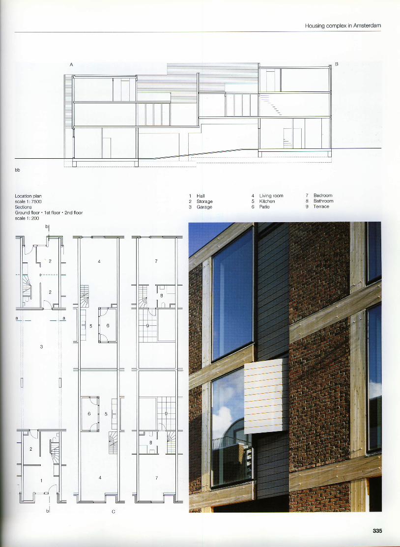
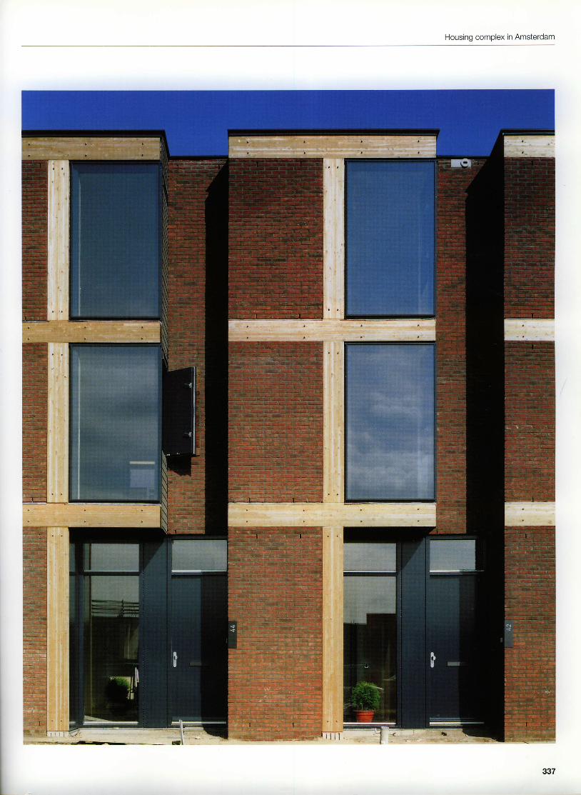
Housing complex in Amsterdam,The Netherlands
1998
Architects:Atelier Zeinstra, van der Pol, AmsterdamProject architect:Herman ZeinstraAssistants:Harriet Dil, Martin Fredriks, Sjoerd Landmann,Mechthild StuhlmacherStructural engineers:Bouwstart, Amsterdam
Development of the two peninsulas of Sporen-borg and Borneo for inner-city housing in theeastern part of Amsterdam's dockyards beganin 1987. The docks here had not been used formany years and the buildings were occupiedby squatters and artists. Refurbishment hadbeen planned since the 1970s and was longoverdue. The master plan rigorously pre-scribed a three-storey blanket developmentdisected by parallel streets every 30-40 m.The development plan provided for a numberof different types of housing which, however,had to comply with very strict rules. Forinstance, the ground floor had to be 3.5 m highin order to guarantee alternative uses, andeach building had to occupy an entire plot,including parking and external facil i t ies. And allthe facades had to be uniform - finished withthe same type of brick.The "back-to-back" apaftments do not haveindividual carports but a garage within theblock instead. The constricted plan layoutsmeasuring 4.2 m wide and 14.5 m long are l itvia a patio. The second floor contains one bed-room, a small bathroom and a rooftop terrace.The short spans enable the use of 190 mmreinforced concrete slabs spanning transverse-ly which are supported on the 230 mm con-crete party walls. Consequently, the externalwalls on the south and north elevations can beof a lightweight timber construction.Nevertheless, the stipulation to use bricks wascomplied with by constructing the infill panelsbetween the glulam beams and columns in110 mm facing brickwork. Opening panels areincorporated in the side of a recess in thesouth facade. Fixed windows are positionedflush with the loadbearing timber members.The elegant interplay between brickwork, tim-ber and glass lends these buildings their spe-cial character.
Section through facadeHorizontal section through recess in facadescale 1: 20
1 9
2021
23
zc
2627282930
31
2
45o
7
Parapet trim, aluminium section,40 mm dia., coatedLaminated veneer lumber (LVL)board, 18 mmFibre-reinforced cementboard, 16 mmnnan narnanr l
Foil, water-repellentThermal insulation,75 mm mineral woolWall construction:100 mm facing brickwork48 mm air spacefoil, water-repellent, open todiffusiontimber post-and-rail construction,119 x 38 mmthermal insulation, 120 mm glasswoolvapour barrier, polyethylenesheeting12.5 mm plasterboardSole plateThermal insulation,80 mm mineral woolFixing anchor, steel angle, cast inReinforced concrete slab, 190 mmSteel angle, 140 x 40 x 8 mm,fixed to slabFloor finish, 50 mmLVL board, 12 mmSteel angle supportLVL board, 15 mmRibbed reinforced concrete floorPrecast concrete element, 30 mm
Thermal insulation, 50 mm rigidexpanded foamSheeting, waterrepellentCapping, bent sheet steelUpstand, gas concrete, 100 mmWaterproofing, 2 layersThermal insulation, rigidexpanded foam with integralfallsSheet steel brackets at1000 mm centresSteel angle, 100 x 120 x 10 mmFlashing, lead sheetSteel angle, 90 x 90 x 10 mmFixing boltsGlulam beam, impregnated,353 x 110 mmWall construction:100 mm facing brickwork45 mm air spacethermal insulation, 75 mmmineral wool230 mm reinforced concreteGlulam column, 316 x 110 mmConstruction of opening panel:20 mm profiled boards15 mm air spacefoil, water-repellent, open todiffusionthermal insulation, 70 mm rigidexpanded foamvapour barrierLVL board, 12 mm
Bel Colle Park is located near the town of Hors-holm in the vicinity of The Sound amid anundulating landscape with a good stock oflarge, mature trees. Locally, it is one of themost sought-after areas among house-buyers.The group of 18 two-storey semidetachedproperties is arranged to follow the topographyof the site.The land slooes down towards the south-eastand in doing so forms a shallow depression.The houses have been carefully placedbetween the existing trees towards the top ofthe slope. Access is by means of a privatedriveway (cul-de-sac) on the northern sidewhich curves to follow the topography.Two types of house are available: semi-detached with or without bay. Further differ-ences are evident in the shaoe of the windowsand in slight variations to the living rooms,which leads to minor differences in the usablespace available. Each block of two houses isdivided in the centre and the plan layouts aremirrored. Only the rooms on the first floor couldbe assigned alternative uses.The loadbearing internal and external walls ofthe buildings comprise 120 mm precast con-crete elements, the non-loadbearing walls gasconcrete panels. Hollow concrete planks formthe upper floors and the roof structures are oftimber. The loadbearing leaf of the externalwall is enclosed by 150 mm cavity insulation,while the 115 mm outer leaf of facing briclarorkempbyd'stretcher bond with flush joints. Thewindows, partly fixed lights, partly opening out-wards, are positioned flush with the outsideface of lhe masonry. The cantilevering baysare supported on steel columns and beams.These bUildings with their light-coloured facingmasonry, long overhanging eaves and simpletimber details blend in harmoniouslv with theirnatural surrqundings.
190 x 400 mmm16 Timber section, oak17 Floorconstruction:
parquet flooring on supportingmembersdamp proof membranereinforced concrele slab
18 Plasterboard, 13 mm19 Window sill, MDF board, 30 mm
41
Example 26
Apartment block in Salamanca, Spain
1 998
Architect:Jes0s Maria Aparicio Guisado, MadridAssistants:Luis lgnacio Aguirre Lopez,Daniel Huertas Nadel,H6ctor Fern6n dez Elorza,Carlos Pesqueira CalvoStructural engineer:Valeriano de Diego
This apartment block is situated in Santa Martade Tormes, a suburb of the Spanish universitytown of Salamanca. Set amid the typical apart-ment block architecture, it stands out conspic-uously from its surroundings.This is a crisp-outlined, five-storey block, oneside of which abuts a neighbouring building.Four red-brick masonry storeys are supportedon a rough-finish concrete plinth. The centralsection is characterized by the restrainedfenestration. The long ribbon windows at theends continue around the corners of the openend of the building and terminate on the nar-row side. This four units per floor layout with itselongated stair shaft contains well-structuredapartments, each with three large, separaterooms of almost equal size plus a spacious liv-ing area with kitchen, bathroom, storage spaceand built- in cupboards.The entrance lobbies are small but functionaland well proportioned.The top storey, with its large openings framedin concrete, guarantees a conspicuousappearance. Therefore, this storey stands outclearly from the others, signall ing a usage dif-ferent to that of the standard floors.There are only two apartments on the top floor.These were given an additional external zone,with enough space for a rooftop garden andeven a small pool for each apartment, by plac-ing the external walls to the apartments backwithin the building. The enclosing masonrywalls create a private, couftyard-type area. Thelarge openings in the outer walls permit gener-ous views of the surroundings. The quality ofthis apartment block l ies in such carefullyformulated, uncommon soatial situations. Theireffect is reinforced by the use of just a few,coordinated materials and simole details.
u2
Aoartment block in Salamanca
Top storeyStandard storeySections through top storeyscale 1:400LUUauur I p rar I
scale 1:3000
Example 26
w
Aoartment block in Salamanca
Section through west facadescale 1:20
Upsrde-down roof construction:gravelthermal insulation, 40 mm rigidexpanded foamwaterproofingscreed laid to falls, 140-80 mm240 mm reinforced concrete slab15 mm plasterFixed glazing, 12 mm laminatedsafety glassFloor construction, top storey:natural stone slabs,600 x 300 x 20 mm20 mm mortar bed20 mm sand10 mm levelling mortar45 mm precast concrete tilessleeper walls240 mm reinforced concrete slab20 mm plasterRoof construction, terrace:natural stone slabs,600 x 300 x 20 mmsleeper walls, precast concreteelementsthermal insulation, 30 mm rigidexpanded foamexpanded clay, max. 55 mm onwaterproofing
screed laid to falls, max. 120 mm240 mm reinforced concrete slab20 mm plasterBalustrade, 12 mm laminated safety glassReveal, fair-face concreteWall construction:115 mm clay brickwork, flush mortar joints15 mm plaster fill, waterrepellentthermal insulation, 60 mm glass wool70 mm air space70 mm horizontally perforated clay bricks20 mm olasterRoller shutter boxAluminium window, stove enamelled,with insulating glazingSoandrel wall construction:115 mm clay brickwork, flush mortar joints15 mm plaster fill, water-repellentthermal insulation, 60 mm glass wool70 mm horizontally perforated clay bricks20 mm plasterFloor construction, standard storey:natural stone slabs, 600 x 300 x 20 mm20 mm mortar bed20 mm sand240 mm reinforced concrete slab
The centre of the rather rural-looking town ofLochau at the eastern eltremity of Lake Con-stance is dominated by a busy throughroadcarrying traffic to and from the nearby border.Situated on this road are the church, the coun-cil offices, a number of small hotels and thenew, detached vicarage. This clarifies in a sim-ple way the spatial relationships both to thechurch and to the surrounding houses, lendingstructure and intensity to the urban planning ofthe centre of the town. This no-nonsense build-ing solves problems of function and architec-tural form within its simple structure.Two arcades help to overcome the change inlevels atthe edge ofthe church square, butalso create a reference point for thestreetscape, the open square. At street levelthere is a shop behind the arcade; the floorabove contains the large parish hall, whichlooks out onto the forecourt to the vicarage.The hall can be divided into two sections byway of a glazed sliding partition. The facadesof the building are plain, without recesses orprojections, the windows flush with the outsideface. They convey the impression of a homo-geneous envelope enclosing the building.Merely the arcades provide texture and depth.The loadbearing consfuction of the buildingconsists of a reinforced concrete frame withfloors of hollow concrete planks. Timber studwalls form the infill panels to the frame -withcolumns on a 3,0 m grid. Therefore, the'120 mm outer skin had to be built as a free-standing masonry ledf extending the full heightof the building, The brickwork is connected tothe concrete frame via stainless steel anchors.All lintels are carried on stainless steel anglesso that the stretcher bond of the facing brick-work and hence the structure of the envelooeis maintained throughout. Along the arcadesthe brickrruork skin is reduced to a 25 mm brickslip cladding to the concrete lintels. Thiscladding, in a slightly different colour, is alsocaried around the corners of the building tomatch.
i- i i- i ;- i r iff i f i-----------t -----------tt ----------------tt u lt -fli l i l i l mrr _fl|l l l l s i lB ' J r f f ill ll ll NTrnmu u u | f f i
Horiz. section through door-pier junctionHorizontal section through pier-fixedglazing junction
Wall construction:1 27 mm facing brickvvork anchored toconcrete frame40 mm air spacethermal insulation, 60 mm glass woolconcrete frame: 200m concretebeamVcolumns15 mm thermal insulation12.5 mm plasterboardvapour barrier12.5 mm plasterboard, with skim coatand paint finishThermal insulation, 100 mm rigidexpanded foamSilicone jointWooden window, opening light, oak,with triple glazingFloor construction:100 mm oak planking60 x 80 mm timber battens
Sectionscale 1:20
thermal insulation, 80 mm mineral wool360 mm hollow concrete planks, withskim coat and paint finishVentilation slotFacing brickwork, 115 mm, withhorizontal reinforcement every4th-sth courseTimber stud wall construction:5 mm hardboard120 x 60 mm timber studsthermal insulation, 120 mm mineral wool18 mm oriented strand board (OSB)services plane, with thermal insulation,50 mm mineral wool12.5 mm plasterboardvapour barrier12.5 mm plasterboard, with skim coatand paint finishStainless steel Z-section, withelongated holes
o7
4
349
Example 27
350
Communitv centre in Lochau
Section through arcade facadeHorizontal section through windowHorizontal section through fixed glazingscale 1:20
50 mm gravelwaterproofingthermal insulation, 200 mm rigidaYnan. la . l f ^^m
vapour barrierscreed laid to falls360 mm hollow concrete planks, withskim coat and paint finish
Concrete upstandLintel, precast concrete, cladin 25 mm brick slipsConcrete column,230 x 250 mm, with facingbrickwork claddingThermal insulation,120 mm rigid expanded foamReinforced concrete wall,waterproof, 250 mm
5
6
351
Example 28
Church and community centre inNeu-Anspach, Germany
The new community centre with church andparish hall is located in the immediate proxim-ity of the market-place. The scale of this large,detached cube integrates well with the hetero-geneous architecture of the town centre. Thedesign and shape bf the church structure pro-vides an unobtrusive setting for introspectivequietness.The glazed foyer links the two blocks roughlyequal in size: the introverted church on oneside, the community centre with offices, meet-ing rooms and apartments on the other. Theinternal layout is determined by the spaciousfoyer. A glazed partition with large, glass slid-ing screens to the church, and the commonroof construction create a visual bond. Whenthe sliding screens are open, the foyer servesas an extension to the church.Besides the graphic configuration of the overallbuilding, the two parts are also distinguishedby the choice of facade material and the open-ings. Reinforced concrete walls constitute theprimary loadbearing structure. These enablediverse openings for windows and loggias tobe positioned as required. The facades of thetwo parts are different: the almost completelyplain surfaces of the church structure contrastwith the carefully worked rendered surfaceswith their precisely located windows. The ren-dered surfaces conceal a "thermoskin" withmineral f ibre insulation. Parapet cappings andwindow reveals make use of narrow aluminiumsheets. The church employs a partial-fill cavitywall construction; blocks of Noruuegian whiteconcrete were used for the outer leaf.One essential charm of this fine material differ-entiation lies in the treatment of the white mason-ry. The even stretcher bond is given a patternby the graphic arrangement of the necessarymovement joints. In each case the bondrestarts at the joint. The corners were built inbond in such a way that the observer is giventhe impressioo of a continuous external skin.
Section through roofSection through facade to churchHorizontal section through window slitscale 1:20
354
Church and community centre in Neu-Anspach
12
Parapet capping, 0.8 mm zinc sheetWall construction:90 mm white concrete bricks6O mm air soacethermal insulation, 80 mm mineral fibre250 mm reinforced concrete95 mm air soace1 15 mm white concrete bricksAngle bracket, 8 mm stainless st€elAluminium window, with insulating glaz-ing, inner pane of I mm laminatedsafety glass, sand-blasted
Aluminium sheet,3 mm,bent to suitFloor construction:20 mm natural stone slabs20 mm mortar bed50 mm cement screedseparating membrane, 0.2 mmpolyethylene sheetingimpact sound insulation,60 mmrigid expanded foam200 mm reinforced concrete slab50 mm thermal insualtion
4
355
Example 28
Corner window to churchHorizontal section . Vertical sectionscale 1:20
1 Stainless steel angle, 8 mm2 Aluminium sheet, 3 mm, bent to suit3 Aluminium window, with insulating glazing,
inner pane of I mm laminated safety glass,sand blasted
4 Ventilation grille, 50 x 15 x 2 mm aluminiumsections
Fresh-air duct, 500 x 300 mm,sheet steel, galvanizedWall construction:15 mm mineral rendering120 mm thermal insulation240 mm reinforced concrete wall15 mm internal plaster
Located between St Gotthard and Bellinzonain the Ticino Alps, a traditional granite miningdistrict, this community was given several newbuildings to meet the needs of today's infra-structure but provide a respectful complementto the old, intact, village structure. One afterthe other, the chapel, the town hall and thesquare in the southern part of lragna wererealized by the same architects. The use ofthe local stone with its oowerful texture illus-trates the bond between the new structuresand the history of the vil lage. Using simplebuilding geomelries they relate to the characterof the village, although the structures them-selves are a deliberate, contemporary com-ment on their surroundings.
The highlighting of structural elements, like theplinth in fair-face concrete or the exposededges of the floors, serye as a stylized archi-tectural link between tradition and modernism.This approach makes possible large ribbonwindows on the town hall, likewise large panelsof glass bricks. With outer leaves of naturalstone, the buildings generate a reference tothe authenticity of the village without intruding.The twin-leaf external walls are made fromsquared gneiss stones, insulation and plas-tered clay brict<work. The hammer-dressednatural stone masonry in Roman bond is builtusing cement mortar and a galvanized rein-forcing lattice in front of the 80 mm thick ther-mal insulation. The floors which pass throughthe walls and act as supports are provided withstrips of insulation internally (a form of con-struction which is hardly feasible on the northside of the Alps owing to the climate and thestrict regulations). Therefore, it is possible tosee the stone masonry wall not as a mereenvelope but also in its structural capacity.
- t -z t| 2t"'Z1 'ot\
Example 29
o l
Town hall2nd floor1st floorGround floorNorth elevationSectionsscale 1:400
Section through north facadescale 1:20
1 Roof construction:60 mm gravelprotective membrane, non-woven fabricwaterproofing and thermal insulation of 80 mm in-situplastic foam200 mm reinforced concrete slab15 mm gypsum plaster
23
Capping, 0.2 mm copper sheetMDF board, 15 mmWall construction:gneiss stone, 200-500 x 100-170 x 100-250 mmcement mortar with galvanized reinforcing latticethermal insulation, 80 mm in-situ foam150.mm clay brickwork15 mm gypsum plasterFloor construction:10 mm parquet flooring70 mm cement screedseparating membrane20 mm jmpact sound insulation220 mm reinforced concrete slab1 5 mm gypsum plasterFair-face concrete surfaceThermal insulation, 30 mm rigid expanded foamWindow sill, 40 mm reconstituted stoneColumn, steel circular hollow section, 200 dia. x 5.6 mmGlass bricks, 200 x 200 x 80 mmSteel channel , 120 x 80 x 5 mmPrecast concrete thresholdGranite slabs, 40 mm, on sand or cement bed
67II
1 01 11 2I J
358
-
Community buildings in lragna
W ILWt llwt tlf f i i l
trfi(t lll
359
Example 30
Bank extension in Schiinaich, Germany
1 999
Architects:Kaag + Schwarz, StuttgartWerner Kaag, Rudolf SchwarzAssistants:Thorsten Kock, Almut Schwabe,Horst Fischer, Marcus LembachStructural engineers:Merkt + Le, Boblingen
The special feature of this extension to anexisting bank building l ies in the unusual con-struction of the natural stone facade. lt is builtfrom 115 mm thick Gauinger travertine stone.In contrast to conventional techniques using asthin as possible a cladding of slabs , there arecurrently few examples of the use of this mater-ial in a proper and structurally lucid form.The proporlions of the extension are derivedfrom the existing urban relationships and build-ing l ines. The building is made up of a stone-faced structure and a glass link which containsthe vertical and horizontal access routes. Thenew facades embrace the forecourt adjacentthe street and clearly assign this to the bankcomprex,The loadbearing construction consists of rein-forced concrete walls 200 mm thick and flatslabs, which can be used as heat storagemedia. The outermost layer of the partial-fillcavity wall construction employs large naturalstone blocks with thin joints built in stretcherbond. The sizes of the stones decrease towardsthe tops of the walls. Near the parapet in par-ticular, the stones are shallower and narrower.This has an economic advantage becausethere is less wastage, but another benefit is thatthis form of construction reinforces the naturaland animated effect of the bush-hammeredstone surfaces. Lintels to doors and windowsare made from a single stone in each case.The relieving l intel above is slightly cambered,which makes it visible as a structural elementand illustrates the jointing principles of a stonefacade.
360
lF lhE_r- - +_s l
L l l - - l
l J- l l l l l !L l l l t l
Sect ion2nd f loors c a l e 1 : 5 0 0Horizonta section through door to []eet ng roo|lrintefl.ra wa I on 2r'rd floorS a I o r l ' - r o r , J h J J . . O o r l o ̂ r l r . l . l - 1 ' r r , 1 ' c l
s c a e 1 : 1 0
Wa I construct on, externa :1 15 rnm Gau nger t ravert lne stone n rnasonry bondbush-hanrnrered surface2 0 m m a r s p a c etl-reflr-lal nsulat on, I00 lrlr n-rir.rera woo200 mm re nforced conc[eteGau nger t ravert ine stone n luasorrry bond 1 15 t t r rn.bush-harrrrered s l r r face door l in te l provided wi thcantber for st ructura re l e l
Bank extension in Schonaich
lvortar f I ng, 20 [r[r
Reir.lforced corcfete wa I
S tee -anc l g lass facade o f we ded s tee l la ts w t l l
nsu la t ng g az ngF loor cons t ruc t ion . g ro lnd l loor to cer l t ra l la l :
20 nrn natural stone TaUern greetr
20 rr-r-l r.lrortar bed
60 i rn r anhydr i te sc reed w th t l t rder f loor heat ing
50 n.r-r t l lenral and rupact sottrlcl ir lslr at orl
345
t \ t . , : , ^ . 6
irei^
,rli1Jt ll
llt=__l *
lT-il]iLt
r ' . 1 - . e
q
361
Example 30
":'N
West facadeHorizontal sections' Vertical sectionscale 1 :10
o
7I
1
4
c
Parapet coping, Gauinger travertine stone,smooth surfaceLintel to uppermost row of windows, provided withcamber, Gauinger travertine stone in masonry bond,1 15 mm, bush-hammered surfaceOpening lights for night-time ventilation, openedindividually as required, 10 mm toughened safetyglass + 18 mm cavity with sunshading light-deflecting grid + 10 mm toughened safety glass, inblack anodized aluminium sections, plus anti-intruderbars at ground floor onlyRevolving light, black anodized aluminium,8 mm + 16 mm cavity + 12 mm laminated safety glassGuide track for sunshade blind
Fixed glazing in aluminium sections, I mm + 16 mmcavity + 12 mm laminated safety glassFloor duct for heatingRoof construction:elitensive planting / 100 mm gravelsheeting, resistant to root penetrationfilter, non-woven fabricwaterproofing, bitumen sheeting, 2 layers, top layerwith slate granule surfacingthermal insulation, .140 mm rigid expanded foamvaoour oarner250 mm reinforced concrete slab. with undercoat'15 mm internal olaster
362
Bank extension in Schonaich
' u i , r' t - .
' i. :*r ; ! . . . ? i 1 . ', , t , - r -
: r{ n ii:,:,: i i i . r " I i
. '.:.,.,.r, litt '
" i ' ' r: ) ' -
. . t . . i . .
I
363
Example 31
Library of the Technological Institute inCork, lreland
1 996
Architects:Shane de Blacam & John Meagherwith Boyd Barrett, Murphy O'Connor, DublinStructural engineers:Horgan Lynch & Partners, Cork
The library building is part of the overall urbanplan for the Technological Institute. The shapeof the building with its sweeping south facadeis explained by the geometry of the overallcomotex.There is a very strict organization of the internalfunctions from south to north, which starts withthe two-storey reading room and unfolds byway of lively interventions with stairs andgalleries. Up to 500 students can be accom-modated in the large reading room and on thegalleries. The shelves have space for about70,000 books, periodicals and video films.Likewise integrated in the linear structure arerooms for seminars and the library manage-ment. The different heights of the building andthe associated changing lighting conditionsgive the interior an even more pronouncedthree-dimensional effect. Local, traditionalbuilding materials were used for the construc-tion: clay and calcium silicate, oak for the win-dow frames, panelling and furniture. Concretebricks alternating with clay bricks createimpressive patterns on walls and columns.Clay brickwork cladding was positioned in theformwork before casting the in-situ reinforcedconcrete columns and arches. The diaphragmwall construction (max. spacing betweenleaves 550 mm) offers numerous opportunitiesfor projections and recesses which can beused for built-in furniture. The curving southelevation almost devoid of windows oresents astark contrast to the brightly lit and contrastinginterior of the library.
.H E, lt$"rLF lll, l - 6' f f i" l l lb' -.H E. llli,q p I[EdL N- )
! [ ]3E U.1 ho o! P n E
it
J
1:III
ii
I
,
- n " _ . t l | l- lFE E l lrtrl\l :a _El [i
. " fll .+t. lill{ l i l qF i l t l.E B. ilU .H E. l|Uq___E [n q_F [n.{F. II l l .{r, l l l lq F i l q P i l t l,E E. [U "E E. ll[q F r q F I[-Ert x EdL
u_ [q F q Fq F q Ft r t r o t r t r e- 1 h r l h "
: E : E
I E F-* [qr ll F
lTlt . . fllilil rE ltil|lu .d b" |JuI t q F t tt x_EdL! - _ [
Parapet capping, calcium silicate slab, 450 x 20 mmDrip plate, stainless ste€|, bent to suitRoof construction:20 mm mastic asphalt on separating membrane60 mm thermal insulationvapour barrier150 mm in-situ reinforced concrete75 mm precast concrete planks
4 Cross-ribs of concret€ briclovork
Wall construction:100 mm clay briclovork310 mm cavity50 mm thermal insulation100 mm concrete brickworkFloor construction, gallery:coconut fibre carpet150 mm in-situ concrete75 mm precast concrete planksBuilt-in bookshelves, MDF board, coatedPrecast concrete peripheral frame
Waterproofing, bitumen sheetingWindow lintel, calcium silicate block, 65 mmRoofing slates, several layersRoofing slates, 2 layers, laid to fallFloor construction:coconut fibre carpet150 mm in-situ concreteseparating membranethermal insulation, 50 mm rigid expanded foamcement levelling coathardcoreLean mix concrete fillingCalcium silicate pavings eliternally
1 2a a
1 4I A
1 61
7d
I1 01 1
Perforated plate element for permanent ventilation 17Lining to reveal, oak, 150 x 25 mm 18Wooden window, oak, with insulating glazing
A
i l i l t i t l l i l
il tl li l t l
t l l
t l
i l i l
il il tl t i l t l I
i t t l l t t l i l t li l l t t l 1
il tl i l l i l t li l i t l l
il tl t i l t l
366
Library of the Technological Institute in Cork
v,/,/ )mrummmmmmmmm
Example 31
368
Mechanical Engineering Faculty Buibing of the University of Aveiro
Mechanical Engineering Faculty Building ofthe University of Aveiro, Portugal
1 996
Architect:Adalberto Dias, PortoAssistants:A. Teixeira, C, Veloso, J. Eus6bio, V. Gama,J. Miguelote, N. RochaStructural engineer:A. Dinis
Since 1985 a general plan has been in forcefor all newly erected buildings on the new cam-pus of the University of Aveiro. One of theprime considerations was to limit the choice ofarchitect, if feasible, to members of the "Pot1oSchool" in order to give the buildings by differ-ent architects an inner architectural coherency.The effect of this strategy is that the campus isnow also a showcase for Porto's most notablearchitects.The building designed by Adalberto Dias forthe Mechanical Engineering Faculty is in theimmediate vicinity of the buildings for geology(Eduardo Souto de Moura) and mathematics(Carlos Prata).The predefined interior layout of the buildingled to an obvious solution. The south-west ele-vation - with virtually no openings - forms onewall to the access zone, which incorporates thestairs and is lit from above via a long, continu-ous rooflight. The loadbearing structure of thebuilding consists of reinforced concrete in con-junction with steel beams and columns forwalls and floors, some of which have to spanouite considerable distances above the lecturetheatres. The external walls are provided with amasonry outer leaf of approx. 70 mm highcourses of facing brickwork built in stretcherbond. In order to emphasize the radical natureof the concept, the external masonry is given ahorizontal profile. This is achieved by recess-ing every second course by 30 mm. To do this,the bricks were sawn to 80 mm width. Steelsections at the transition between masonry andglass facade and along the edge of the roofstress the horizontal format of the structure.The external wall alongside the rooflight alsofeatures facing brictcrrrork on the inside; theirregularities of this masonry produce a verylively texture when illuminated by the dramaticdiagonal, overhead lighting.
3rd floor ' 2nd floor. Ground floorscale 1:750
tll|llI l lLlt ulm-il
EEEE IIEEHE IIEEEEOIIEEEE OI]EEEE OIIEEEE O
O O E E O
369
Example 32
South-west elevationSectionsscale 1:500Section through facadescale 1:20
on cork board6 Steel channel, 160 mm7 Spandrel panel:
clay brickwork
12 mm air spacethermal insulation, 40 mm rigidexpanded foam1 95 mm reinforced concreteclay bricks30 mm synthetic resin plasterSteel window, with insulating glazingWindow sill, natural stone
10 Floor construction:40 mm natural stone alsbslevelling mortar bedthermal insulation, 30 mm rigidexpanded foamdamp proof membranescreed laid to fallsthermal insulation, 50 mm rigidexpanded foam'180 mm reinforced concrete
tJ
v
370
Mechanical Engineering Faculty Building of the University of Aveiro
1 1 Roof construction:40 mm reconstituted stone pavingslevelling bedthermal insulation, 30 mm rigidexpanded foamwaterproofingscreed laid to falls180 mm reinforced concrete slab40 mm synthetic resin plasterWood/steel window
Synthetic resin plaster, 50 mmClay bricksInternal plaster, 20 mmFloor construction:floor finish of stone slabs20 mm mortar bed40 mm screed180 mm reinforced concrete40 mm timber battens40 mm synthetic resin plaster
I J
1 41 5t o
371
Example 32
372
Mechanical Engineering Faculty Building of the University of Aveiro
SectionsNorth-east elevationscale 1:500Section through facadescale 1:20
17 Wall construction:1 10 x 80 mm clay bricks in stretcherbond12 mm air spacethermal insulation, 40 mm rigidexpanded foam195 mm reinforced concreteclay bricks in stretcher bond,1 1 5 m m
18 Glazed steel door
Plinth construction:clay brickwork50 mm mortar fill ing'195 mm reinforced concreteHorizontal glazing, laminated safetyglass in steel frameSteel angle, 60 x 70 x 8 mmGuide rail for inspection cradlePlasterboard
1 9
20
2223
373
Example 33
Office building in Essen, Germany1996
Architect:Detlef Sommer ofEckert Negwer Sommer Suselbeek, BerlinAssistant:Marc JordiSite manager:Helmut Heimeshoff , EssenStructural engineers:A. Bruns, B. Szafranski, Berlin
This office building at the Christine Coll iery pro-vides a link between the once separate officesand the existing productlon building. The smallplot made it necessary to erect a four-storeybuilding. This contains simple plan layouts withsix offices per floor as well as the associatedvertical and horizontal access zones and ser-vice core. The rooms are arranged alongside acentral corridor. The offset between the twohalves of the building gives rise to an interest-ing spatial effect.Storey-height, narrow windows break up thesimple cube, while the piers provide a rhythmicstructure to the facade. The layout of themasonry is such that the observer gets theimpression of a framework. However, the quali-ty of the design concept manifests itself in theskilful balance between piers and openings.Consequently, special attention was paid tocareful detail ing of the openings.The facing brickwork of the outer leaf consistsof Wittmunder peat-fired bricks with the Olden-burg format. Cavity insulation and loadbearingcalcium silicate masonry complete the externalwall construction. The window reveals are car-ried around the corners with a one-brick-deepbond.The window sills consist of brick-on-edgecourses, the lintels of reinforced concrete cladin facing brickwork. The windows with theirfixed glazing, wooden reveals and woodenopenings lights fitted behind the outer leaf forma distinct contrast to the piers in order to rein-force their effect.lronically, the closed openings l ights, offsetfrom the plane of the window, form their ownpier within the opening and hence consum-mate the architectural setting.The loadbearing walls adjacent the internalcorridors are made from the same material asthe outer leaves of the external walls. They illu-strate the simple structural system: the ex-posed in-situ concrete floors spanning betweenexternal wall and corridor wall, Masonry archi-tecture becomes contemporary when used insuch an exciting, simple yet subtle way.
1 Lobby2 Reception3 Office4 Tea kitchen5 Meeting room6 Existing building
375
Example 33
T!TT
- -tlirilli trt t : l r
lli il376
Office building in Essen
Sectionsscale 1:250WindowElevation . Horizontal sectionSection through facadescale 1:20
A
4
67
Roof construction:50 mm gravelwaterproofing, bitumen sheeting, 3 layersthermal insulation, rigid expanded foam, withintegral falls, 300-120 mm220 reinforced concrete slab, soffit exposed, roughformwork finishLaminated veneer lumber (LVL) board, 450 x 25 mmTimber section. 22O x7O mmFlashing, 1 mm zinc sheet, pre-weatheredParapet capping, 1 mm zinc sheet, pre-weathered,on separating membrane V 13Concrete upstand, 160x400 mmWooden window, meranti with glazed finish, fixedglazing, insulating glazing with laminated safetygrass
I Floor construction:13 mm caroet60 mm screedseparating membrane'17 mm impact sound insulation220 reinforced concrete slab, soffit exposed,rough formwork finish
I Brick-on-edge window sill, Wittmunder pealfiredbricks, Oldenburg format, 52 x 1O5 x 22O mm
10 Thermal insulation, 110 mm mineral fibre'11 Reinforced concrete lintel, brick slip cladding12 Peripheral timber cover strip, 125 x 15 mm'13 Convector heating under grating14 Opening panel with timber infill, meranti with
glazed finish15 Wall construction:
facing brickwork, Wittmunder peat-fired bricks,Oldenburg format, 52 x 105 x 220 mmthermal insulation, 110 mm mineral fibre240 mm calcium silicate brickwork'15 mm gypsum plaster
Situated on the north-western edge of thedevelopment built to coincide with EXPO 2000,this urban component with 87 apartments,public amenities and shops forms the gatewayto Kronsberg, an entirely new city suburb. Thetwo main facades of the building have beengiven different treatments: a brickwork facadewith peat-fired facing bricks and room-heightFrench windows with folding shutters facingthe city, and a timber facade behind continu-ous, deep loggias facing the inner courtyard.The sculptured form of the block with equal-sized window elements distributed evenly overthe facade in an intriguing staggered arrange-ment lends the building both stability andvitality. A large number of different apartments,from simple layout with hall to open plan, ofiersdiverse possibilities with a constant basicstructure.The entire loadbearing structure of the buildingwas built in precast concrete. This resulted infast erection and low building costs. There isan outer leaf of 115 mm facing bricks with a10 mm air space and 120 mm thermal insula-tion. A contrasting precast concrete copingcompletes the parapet. The window lintels,also precast, are clad with clay bricks instretcher bond in order to match the deoth andappearance of the 240 mm reveals. Fitted intothe reveals are wooden folding shutters whichhelp to assert the character of the building. Theprecast concrete window sills round off thehomogeneous appearance of the complex.The facades to the inner courtyard, with theirdeep loggias, are clad in birch plywood. Theseloggias raise the living standards of the com-plex and form the transition to the landscapedinner courtyard, generating a contrast to theurban environment.
Sectionscale 1:250Horizontal section through junction between facing brick-work and timber panel facadeHorizontal section through apartment windowHorizontal section through staircase windowSection through street facadescale 1:20
1 Plywood panel, 18 mm birch, both sides coatedwith phenolic resin
2 Wooden lining, 20O x 40 mm3 Wooden glazed door, with insulating glazing4 Supporting construction, 40 x 40 mm timber sections5 Wall construction:
peat-fired facing bricks, NF 115 mm10 mm air spacethermal insulation, 120 mm mineral fibre180 mm reinforced concrete
6 4-part folding shutters of s-ply timber boarding, withedge beading in weatherproof glue, guide tracks topand bottom, 2 No. 15 mm
7 Balustrade of steel flats, galvanized, micaciousiron oxide coating, 35 x 8 mm
8 \Mndow sill, precast concrete, overhang with drip,50 mm
9 Wooden window, 2 lights, with insulating glazing10 Horizontal-pivotwindow, with insulating glazing,
spandrel pane fixed, inner pane of laminatedsafety glass
pavings in gravel bed15 mm impact sound insulationwaterproofing200 mm thermal insulationvapour barrier220 mm reinforced concrete slab
16 Sheet metal flashing17 ParapeYspandrel panel:
peat-burned facing bricks in stretcher bond,NF 115 mm10 mm air soacethermal insulation, 120 mm mineral fibre1 75 mm aerated concrete
1 81 9202122
Open perpendThermal insulation, 60 mm rigid expanded foamHorizontal groove, with fall to outsideVentilation elementSteel angle as support for window sill
380
Housing complex in Hannover
381
Example 34
Sectionscale 1:20
,..
H-Parapet coping, precastconcreteReinforced concrete lintel, withclay brick slip claddingFlashing, 1 mm titanium-zincsheetRoof construction with extensiveplanting:vegetation layerfilter layer120 mm drainage layerwaterproofing200 mm thermal insulationwaterproofing220 mm reinforcedconcrete slab
5 Wall construction: 10peat-burned facing bricks,N F 1 1 5 m m10 mm air spacethermal insulation, 120 mm 1 1mineral f ibre 12180 mm reinforced concrete wall 13
6 Light ing, 450 x 100 x 100 mm 147 Wooden frame door, with inset
steel frame and insulatingglazing 15
8 Kicker plate, 1 mm brushedstainless steel
9 Reinforced concrete, water-proof, 250 mm
HorizontaFpivot wooden win-dow, wjth insulating glazing,spandrel pane fixed, innerpane of laminated safety glass 16Thermal insulation, 80 mmPlasterboard, 12.5 mm 17Timber section, 180 x 70 mmLaminated veneer lumber(LVL) board, with solid woodedge beading, 28 mmTerrace construction:pavings in gravel bed15 mm impact soundinsulationwaterproofing 18200 mm thermal insulation 19
vapour barrier220 mm reinforcedconcrete slabRoof to balcohy, precastconcrete elementWall construction:plywood, 18 mm birch, bothsides coated with phenolicresin40 mm air spacethermal insulation, 120 mmmineral fibre180 mm reinforced concretewatlMat in steel angle frame220 mm reinforced concrete slab