IG MASONRY SUPPORT SYSTEMS IG BRICK ON SOFFIT SYSTEM (B.O.S.S.+)
This Agrément Certificate Product Sheet(1) relates to the IG Brick On Soffit System (B.O.S.S.+) comprising prefabricated stainless steel units with mechanically secured and adhesively factory-bonded brick slips, for use in external masonry walls.
(1) Hereinafter referred to as ‘Certificate’.
CERTIFICATION INCLUDES:
• factors relating to compliance with Building Regulations where applicable
• factors relating to additional non-regulatory information where applicable
• independently verified technical specification • assessment criteria and technical investigations • design considerations • installation guidance • regular surveillance of production • formal three-yearly review.
KEY FACTORS ASSESSED
Properties in relation to fire — all components of the system are classified as A2-s1, d0 or A1 in accordance with BS EN 13501-1 : 2018 and its use is unrestricted by the national Building Regulations (see section 7). Thermal performance — where the system is used around opening head junctions, it can adequately limit heat loss (see section 8). Condensation risk — where the system is used around opening heads, the risk of local surface condensation will be minimal (see section 9). Durability — provided that the system is designed, installed and used in accordance with this Certificate, it will have a service life of at least 50 years (see section 11).
The BBA has awarded this Certificate to the company named above for the system described herein. This system has been assessed by the BBA as being fit for its intended use provided it is installed, used and maintained as set out in this Certificate.
On behalf of the British Board of Agrément
Date of First issue: 26 November 2019
Brian Moore Director
The BBA is a UKAS accredited certification body – Number 113. The schedule of the current scope of accreditation for product certification is available in pdf format via the UKAS link on the BBA website at www.bbacerts.co.uk
Readers MUST check the validity and latest issue number of this Agrément Certificate by either referring to the BBA website or contacting the BBA directly. Any photographs are for illustrative purposes only, do not constitute advice and should not be relied upon.
British Board of Agrément Bucknalls Lane Watford Herts WD25 9BA
In the opinion of the BBA, the IG Brick On Soffit System (B.O.S.S.+), if installed, used and maintained in accordance with this Certificate, can satisfy or contribute to satisfying the relevant requirements of the following Building Regulations (the presence of a UK map indicates that the subject is related to the Building Regulations in the region or regions of the UK depicted):
The Building Regulations 2010 (England and Wales) (as amended)
Requirement: A1 Loading Comment: The system is acceptable for use as set out in section 6 of this Certificate. Requirement: B3(2) Internal fire spread (structure) Comment: The system can satisfy or contribute to satisfying this Requirement. See section 7 of this
Certificate. Requirement: B4(1) External fire spread
Comment: The system is unrestricted by this Requirement. See Section 7 of this Certificate.
Requirement: L1(a)(b) Conservation of fuel and power Comment: Heads of openings in external walls incorporating the system can adequately limit heat
loss and the risk of condensation. See sections 8.1, 8.2 and 9 of this Certificate. Regulation: Regulation:
7 7(1)
Materials and workmanship (applicable to Wales only) Materials and workmanship (applicable to England only)
Comment: The system is acceptable. See section 11 and the Installation part of this Certificate. Regulation: 7(2) Materials and workmanship (applicable to England only) The system is unrestricted by this Regulation. See section 7 of this Certificate. Regulation: 26 CO2 emission rates for new buildings Regulation: 26A Fabric energy efficiency rates for new dwellings (applicable to England only) Regulation: 26A Primary energy consumption rates for new buildings (applicable to Wales only) Regulation: 26B Fabric performance values for new dwellings (applicable to Wales only) Comment: Heads of openings in external walls incorporating the system can adequately limit heat
loss and the risk of condensation. See sections 8.1, 8.2 and 9 of this Certificate.
The Building (Scotland) Regulations 2004 (as amended)
Regulation: 8(1)(2) Durability, workmanship and fitness of materials Comment: The system is acceptable. See sections 10.2, 10.3 and 11 and the Installation part of this
Certificate. Regulation: 9 Building standards applicable to construction Standard: 1.1(a)(b) Structure Comment: The system is acceptable, with reference to clauses 1.1.1(1)(2) and 1.1.2(1)(2) of this
Standard. See section 6 of this Certificate. Standard: 2.6 Spread to neighbouring buildings Standard: 2.7 Spread on external walls Comment: The system is unrestricted by these Standards, with reference to clauses 2.6.4(1)(2),
2.6.5(1), 2.6.6(2) and 2.7.1(1)(2). See section 7 of this Certificate. Standard: 3.15 Condensation Comment: When incorporated in an external masonry cavity wall, the system can satisfy this
Standard with reference to clauses 3.15.1(1)(2), 3.15.4(1)(2) and 3.15.5(1)(2). See section 9 of this Certificate.
Page 3 of 15
Standard: 6.1 Carbon dioxide emissions Standard: 6.2 Building insulation envelope Comment: Heads of openings in external walls incorporating the system can limit heat loss and the
risk of condensation, with reference to clauses 6.1.2(1), 6.1.6(1), 6.2.3(1), 6.2.4(1), 6.2.5(2), 6.2.6(2), 6.2.10(1) and 6.2.11(2) of these Standards. See sections 8.1, 8.2 and 9 of this Certificate.
Standard: 7.1(a)(b) Statement of sustainability Comment: The system can contribute to meeting the relevant requirements of Regulation 9,
Standards 1 to 6, and therefore will contribute to a construction meeting a bronze level of sustainability as defined in this Standard.
Regulation: 12 Building standards applicable to conversions Comment: All comments given for the system under Regulation 9, Standards 1 to 6, also apply to
this Regulation, with reference to clause 0.12.1(1)(2) and Schedule 6(1)(2). (1) Technical Handbook (Domestic).
(2) Technical Handbook (Non-Domestic).
The Building Regulations (Northern Ireland) 2012 (as amended)
Regulation: 23(a)(i) Fitness of materials and workmanship Comment: (iii)(b)(i) The system acceptable. See section 11 and the Installation part of this Certificate. Regulation: 29 Condensation Comment: The system can contribute to satisfying this Regulation. See section 9 of this Certificate. Regulation: 30 Stability Comment: The system is acceptable as set out in section 6 of this Certificate. Regulation: 36(a) External fire spread Comment: The system is unrestricted under this Regulation. See section 7 of this Certificate. Regulation: 39(a)(i) Conservation measures Regulation: 40 Target carbon dioxide Emission Rate Comment: Heads of openings in external masonry cavity walls incorporating the system can limit
heat loss and the risk of condensation. See sections 8.1, 8.2 and 9 of this Certificate.
Construction (Design and Management) Regulations 2015 Construction (Design and Management) Regulations (Northern Ireland) 2016 Information in this Certificate may assist the client, designer (including Principal Designer) and contractor (including Principal Contractor) to address their obligations under these Regulations. See section: 3 Delivery and site handling (3.3) of this Certificate.
Additional Information
NHBC Standards 2019 In the opinion of the BBA, the IG Brick On Soffit System (B.O.S.S.+), if installed, used and maintained in accordance with this Certificate, can satisfy or contribute to satisfying the relevant requirements in relation to NHBC Standards, Chapter 6.9 Curtain walling and cladding.
Page 4 of 15
Technical Specification
1 Description 1.1 The IG Brick On Soffit System (B.O.S.S.+) is a prefabricated soffit system comprising brick slips adhesively and mechanically bonded to a stainless steel carrier to achieve project design requirements (see Figures 1 to 4). The stainless steel carrier is designed to be fixed to the underside of the IG Welded Masonry Support System (which is outside the scope of this Certificate). 1.2 The system is available in four standard profiles: BOSS 65 x 215 mm with header bond (see Figure 1 and Table 1), BOSS 65 x 327 mm with stretcher bond (see Figure 2 and Table 2), BOSS 215 x 215 mm half lap bond (see Figure 3 and Table 3) and BOSS 215 x 215 mm with soldier bond (see Figure 4 and Table 4).
Figure 1 BOSS 65 x 215 mm with header bond (welded masonry support, shims and anchor bolts are outside the scope of this Certificate)
Page 5 of 15
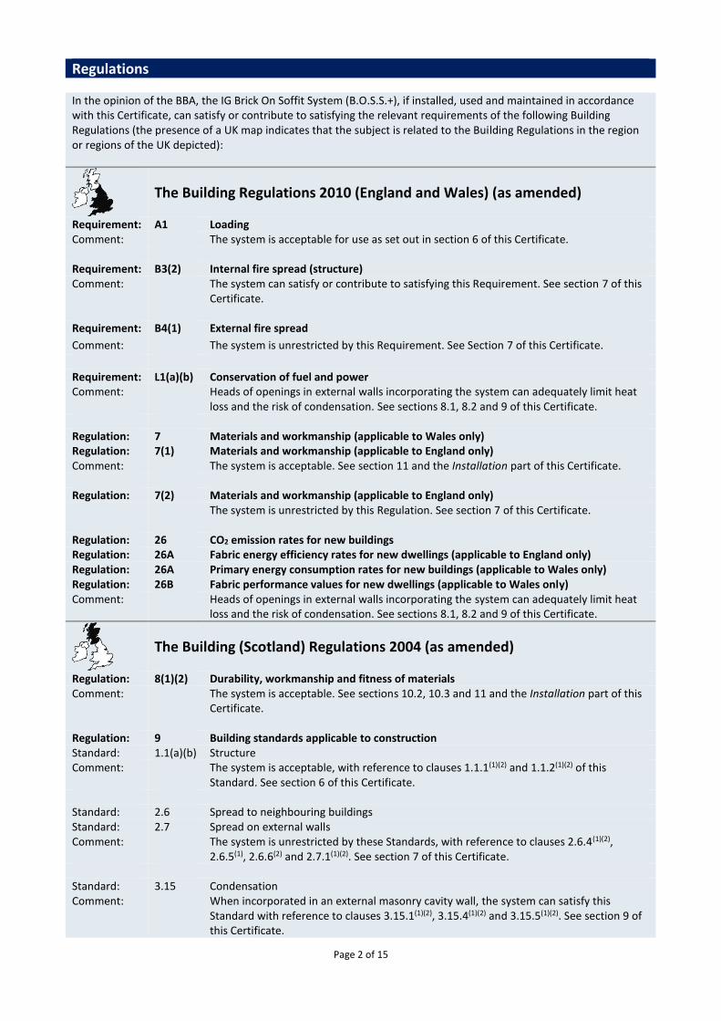
Figure 2 BOSS 65 x 327 mm with stretcher bond (welded masonry support, shims and anchor bolts are outside the scope of this Certificate)
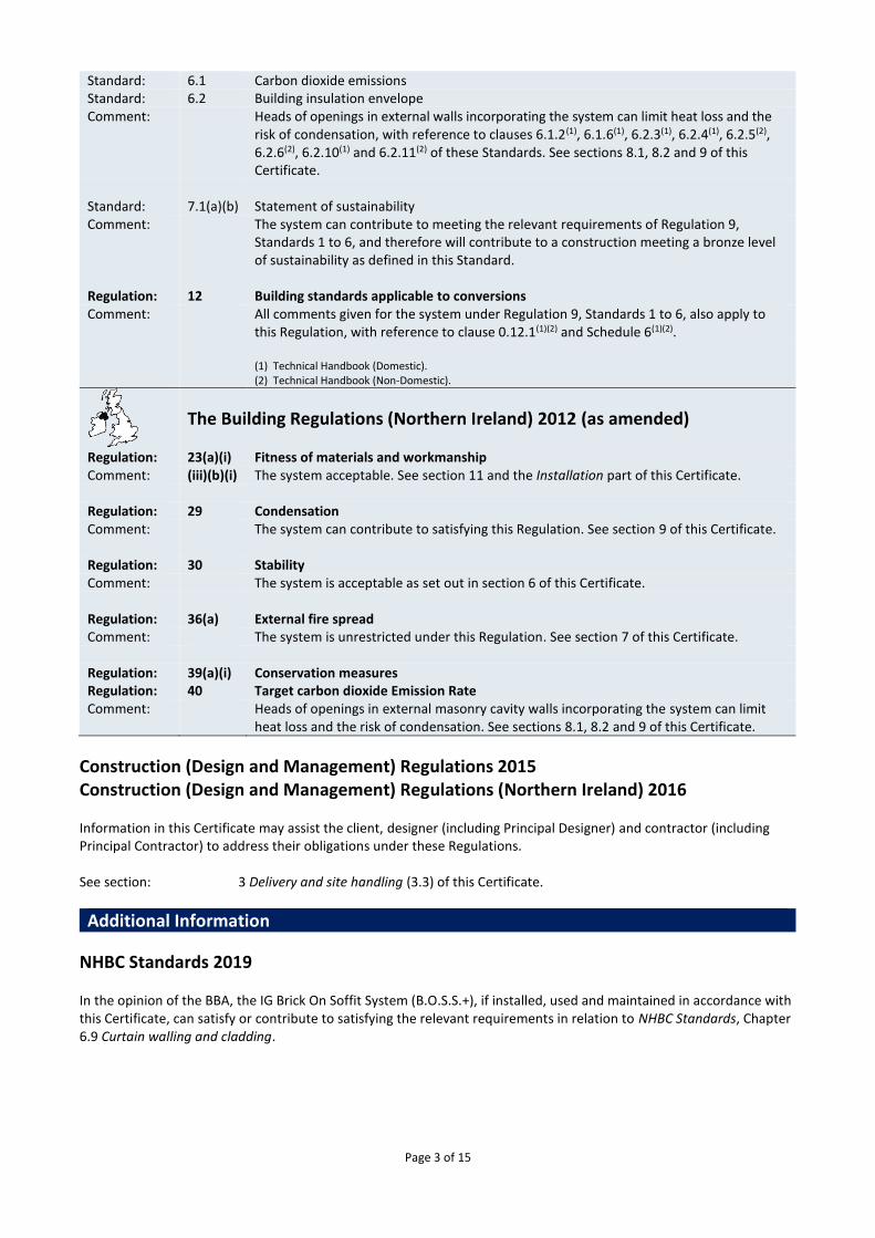
Figure 3 BOSS 215 x 215 mm with half lap bond (welded masonry support, shims and anchor bolts are outside the scope of this Certificate)
Page 6 of 15
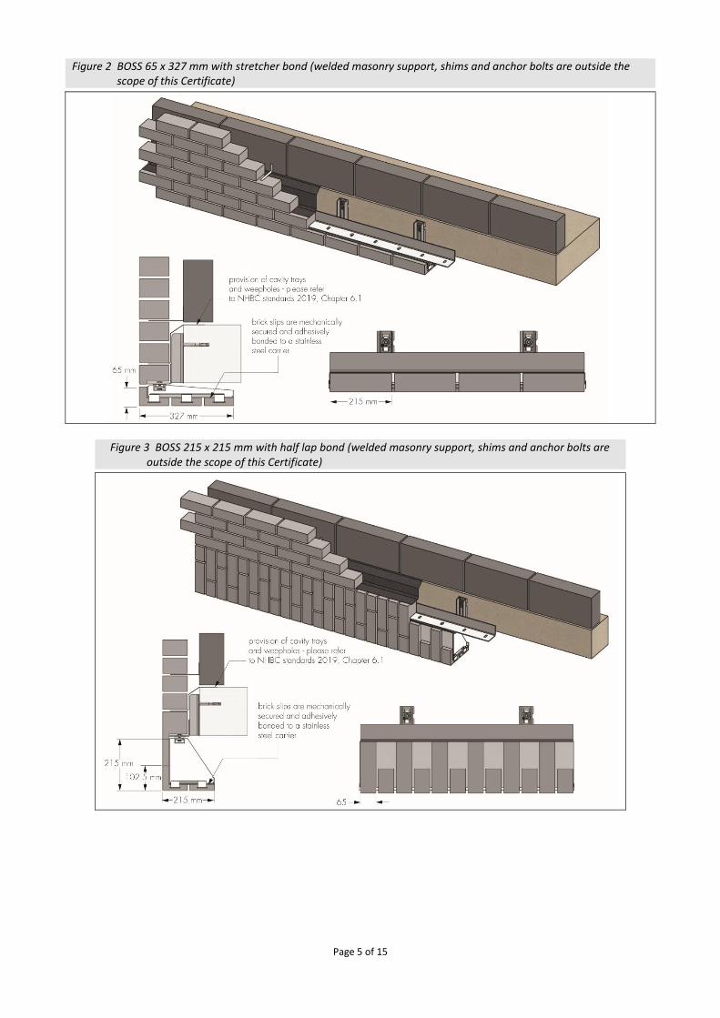
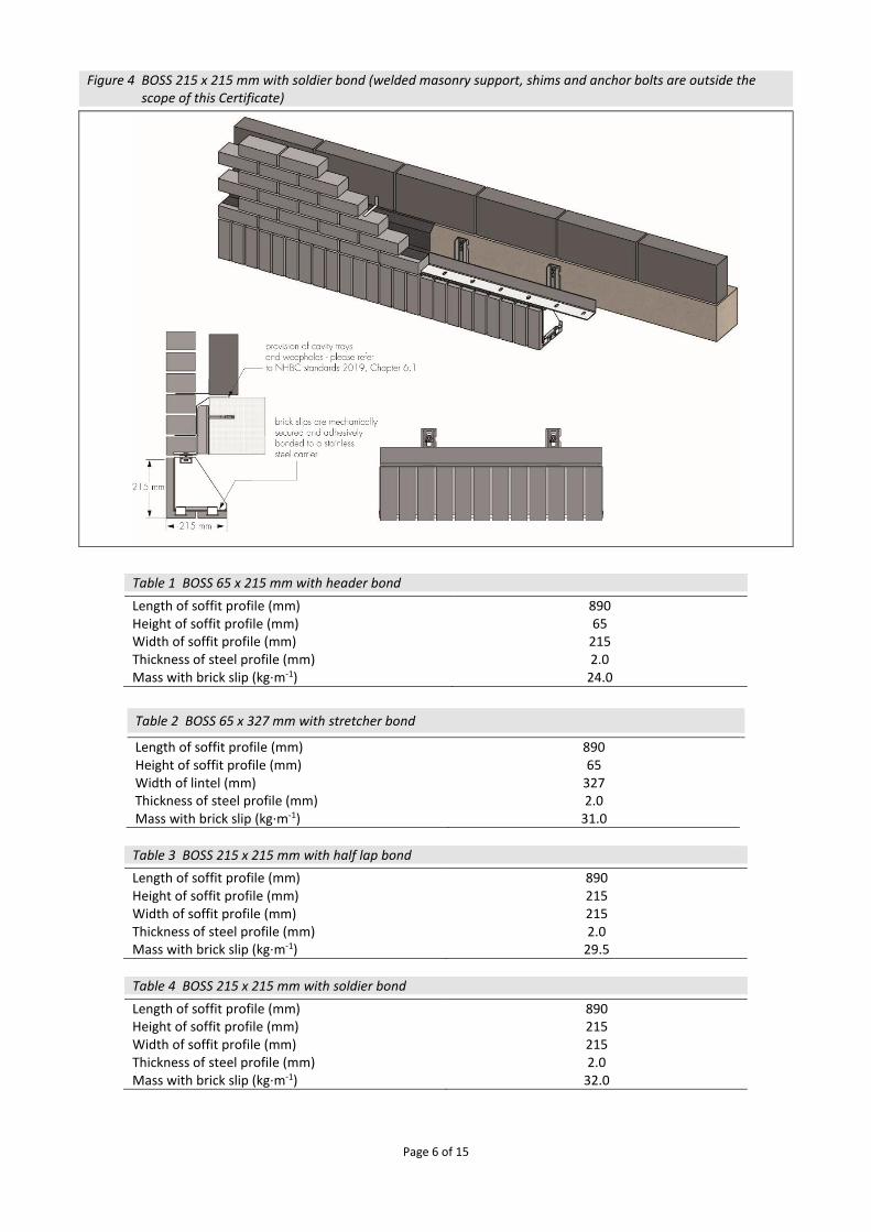
Figure 4 BOSS 215 x 215 mm with soldier bond (welded masonry support, shims and anchor bolts are outside the scope of this Certificate)
Table 1 BOSS 65 x 215 mm with header bond Length of soffit profile (mm) 890 Height of soffit profile (mm) 65 Width of soffit profile (mm) 215 Thickness of steel profile (mm) 2.0 Mass with brick slip (kg∙m-1) 24.0
Table 2 BOSS 65 x 327 mm with stretcher bond
Length of soffit profile (mm) 890 Height of soffit profile (mm) 65 Width of lintel (mm) 327 Thickness of steel profile (mm) 2.0 Mass with brick slip (kg∙m-1) 31.0
Table 3 BOSS 215 x 215 mm with half lap bond
Length of soffit profile (mm) 890 Height of soffit profile (mm) 215 Width of soffit profile (mm) 215 Thickness of steel profile (mm) 2.0 Mass with brick slip (kg∙m-1) 29.5
Table 4 BOSS 215 x 215 mm with soldier bond
Length of soffit profile (mm) 890 Height of soffit profile (mm) 215 Width of soffit profile (mm) 215 Thickness of steel profile (mm) 2.0 Mass with brick slip (kg∙m-1) 32.0
Page 7 of 15
1.3 The system comprises:
brick slip façade — created from 25 mm thick brick slips cut from standard brick masonry units to BS EN 771-1 : 2011 or BS EN 771-2 : 2011.
IG Mech-Fix — a 3 mm thick adhesive used to bond the brick slips to the soffit plates
Self tapping M3.5 x 16 screws — manufactured using A2 stainless steel
perforated soffit plates, gusset plates and channel — manufactured using austenitic stainless steel to BS EN 10028-7 : 2016, Grade 304 2B (Grade 1.4301/1.4307 or Grade 1.4301/1.4307 HR) or Grade 316 (Grade 1.4401/1.4404). The profiles are fabricated by folding.
Cembrit Windstopper Extreme — a breathable sheathing board designed to absorb and release moisture in accordance with BS EN 12467 : 2012.
1.4 Ancillary items used with the system, but outside the scope of this Certificate, are:
the IG Welded Masonry Support (WMS) System — comprising brackets, support angles, shims and anchor bolts including stainless steel lock washers. All elements are manufactured in Grade 1.4301 or Grade 1.4401 austenitic stainless steel
wall ties
expansion joint mastic sealant — pointing mortar colour matched to the mortar to ensure it blends seamlessly with the surrounding brickwork.
2 Manufacture 2.1 The stainless steel profile is manufactured from sheet material which is folded and formed in the factory. 2.2 The brick slips are cut from bricks, then factory-fixed using ‘IG Mech-Fix’ and mechanically secured to the soffit unit. 2.3 As part of the assessment and ongoing surveillance of product quality, the BBA has:
agreed with the manufacturer the quality control procedures and product testing to be undertaken
assessed and agreed the quality control operated over batches of incoming materials
monitored the production process and verified that it is in accordance with the documented process
evaluated the process for management of nonconformities
checked that equipment has been properly tested and calibrated
undertaken to carry out the above measures on a regular basis through a surveillance process, to verify that the specifications and quality control operated by the manufacturer are being maintained.
2.4 The management system of the Keystone Group has been assessed and registered as meeting the requirements of BS EN ISO 9001 : 2015 and BS EN ISO 14001 : 2015 by BSI (Certificates FM 523686, IG, ISO 9001 : 2015; FM 21541, Keystone Lintels Ltd, ISO 9001 : 2015 and EMS553955, Keystone Group, ISO 14001 : 2015 respectively).
3 Delivery and site handling 3.1 The system is delivered to site or to builders’ merchants at specified lengths, each carrying a label bearing the Certificate holder’s name. The BBA logo incorporating the number of this Certificate is marked on each system. 3.2 Reasonable care must be taken during unloading, stacking and storage to avoid damage to the system. A system that has suffered deformation or damage must not be used. Any damage to the brick, steel or bond between the brick and steel must be assessed by the Certificate holder. Repairs of the bond between the brick and steel must only be carried out by the Certificate holder. 3.3 The system must be stored off the ground in such a manner as to avoid the risk of mechanical damage or contamination by corrosive substances.
Page 8 of 15
Assessment and Technical Investigations The following is a summary of the assessment and technical investigations carried out on the IG Brick On Soffit System (B.O.S.S.+).
Design Considerations
4 Use 4.1 The IG Brick On Soffit System (B.O.S.S.+) is satisfactory for use in brickwork and/or blockwork walls in conjunction with the IG Welded Masonry Support System. 4.2 It is important for designers, planners, contractors and/or installers to ensure that the installation of the system is in accordance with the Certificate holder's instructions and the information given in this Certificate. 4.3 The cavity wall construction should be in accordance with the recommendations of PD 6697 : 2010 and where applicable, NHBC Standards 2019, in respect of provision of cavity trays and weepholes.
5 Practicability of installation The system is designed to be installed by a competent general builder, or a contractor, experienced with this type of system.
6 Structural performance
6.1 The IG Brick On Soffit System (B.O.S.S.+) has adequate strength and stiffness to sustain its own weight and imposed wind actions, provided the IG Welded Masonry Support System is designed to support the imposed loads and limit the deflections and is installed by an appropriately qualified individual. The system is not designed to take any load other than its own self-weight and wind action and must be separated from the walling above by the expansion joint mastic sealant.
6.2 The characteristic wind loads on the system should be calculated in accordance with BS EN 1991-1-4 : 2005. Special consideration should be given to locations with high wind-load pressure coefficients. In accordance with BS EN 1990 : 2002, a partial factor of 1.5 should be used to determine the design wind load to be resisted by the system. 6.3 An assessment of the structural performance for a particular building must be carried out by a suitably qualified and experienced individual to confirm that the proposed system provides adequate resistance to design wind loads and transfers them through the masonry support system to the structure. 6.4 The characteristic bond resistance between the soffit plate and brick slips derived from test results is 43.3 kN·m–2. The design resistance of the bond between the soffit plate and brick slips should be taken as the characteristic bond resistance divided by a partial factor of 9. 6.5 In addition to the requirements specifically referred to in this Certificate, structures of brickwork or blockwork in which the system is incorporated must be designed and constructed in accordance with BS EN 1996-1-1 : 2005 and BS EN 1996-1-2 : 2005 and their UK National Annexes, and the following technical specifications of the national Building Regulations, as appropriate: England and Wales — Approved Document A1/2, Part C, Section 1 Scotland — Section 1, Small Building Guide Northern Ireland — Technical Booklet D Structure, Section 3.
Page 9 of 15
7 Properties in relation to fire
All of the system components are classified A2-s1, d0 or A1 in accordance with BS EN 13501 : 2018 and the system is unrestricted in terms of building height and distance to the boundary by the national Building Regulations, provided that it is incorporated in a construction that satisfies the requirements of BS EN 1993-1-2 : 2005 and BS EN 1996-1-2 : 2005, and their UK National Annexes.
8 Thermal performance
8.1 Typical example details containing the system, based on the construction details shown in Figures 1 and 3, were analysed numerically to determine their likely hygrothermal performance.
8.2 If designed appropriately, exposed floor junctions with the insulated system can adequately limit excessive heat loss and allow use of the following Ψ values in carbon emissions rate calculations (see Table 5). Detailed guidance in this respect and on limiting heat loss by air infiltration can be found in the documents referred to in section 9.2.
Table 5 Linear thermal transmittance, Ψ-values, for the IG Brick On Soffit System (B.O.S.S.+)
System Example Ψ value(1)(2)
(W·m-1·K-1) Default Ψ value(3)
(W·m-1·K-1)
215 x 215 mm with soldier bond(4) 0.21 1.0 (1) 120 mm cavity width, comprising 50 mm vented cavity adjacent (R = 0.183 m2·K·W-1), 70 mm insulation. (2) Soffit unit assumed to be filled with loose fill insulation with thermal conductivity, λ = 0.040 W·m·-1·K-1. (3) Where a junction detail has not been calculated in accordance with BS EN ISO 10211 : 2017 and BRE Report BR
497 : 2007, the default value must be used. (4) Assumed wall construction: 102.5 mm brickwork (λ = 0.77 W·m-1·K-1), 50 mm vented cavity [see footnote (1)]
PUR [see footnote (1)] insulation (λ = 0.025 W·m-1·K-1), 100 mm blockwork (λ = 0.162 W·m-1·K-1, inclusive of 6.7% mortar bridging), 15 mm service cavity (R = 0.17 m2·K·W-1), 12.5 mm plasterboard (λ = 0.25 W·m-1·K-1). Assumed intermediate floor slab: 225 mm dense reinforced concrete slab (λ=2.5 W·m-1·K-1).
8.3 For other junction details, the linear thermal transmittance and temperature factor should be calculated in accordance with BS EN ISO 10211 : 2017, following the guidance in BRE Report BR 497 : 2007.
9 Condensation risk
9.1 The construction described in section 8.1 will achieve a surface temperature factor (fRsi), in excess of 0.80, which can be compared to the critical temperature factors (fCRsi), in BRE Information Paper IP 1/06 for the relevant building type. The risk of surface condensation is low when the fRsi is equal to or greater than the fCRsi. The system can therefore contribute to limiting the risk of surface condensation in buildings of some building types. For other constructions, the fRsi must be established by numerical modelling (see section 8.3).
9.2 Further guidance on limiting the risk of surface condensation can be found in: England and Wales — Limiting thermal bridging and air leakage: Robust construction details for dwellings and similar buildings or Accredited Construction Details (version 1.0) Scotland — Accredited Construction Details (Scotland) Northern Ireland — Accredited Construction Details (version 1.0).
10 Maintenance and repair 10.1 If the brick finish becomes damaged or stained the advice of the Certificate holder should be sought.
10.2 Regular checks should be made on the installed system, including:
visual inspection of the brick slips for signs of debonding. Dislodged brick slips must be re-fixed using IG Mech-Fix adhesive
visual inspection of architectural details designed to shed water to confirm that they are performing correctly
Page 10 of 15
visual inspection to ensure that water is not leaking from external downpipes or gutters; such leakage could penetrate behind the brick slips
direct jet cleaning of the brick slips should be avoided and if brick slips are stained the advice of the Certificate holder should be sought.
10.3 Damaged areas must be repaired using the appropriate components and procedures detailed in the Certificate holder’s installation instructions and the advice of the Certificate holder should be sought.
11 Durability
11.1 Provided that the system is designed, installed and used in accordance with the temperature and humidity conditions described in section 9, it will have a service life of at least 50 years.
11.2 The brick slips will have an equivalent durability to the bricks from which they were cut (see section 1.4).
12 Reuse and recyclability 12.1 The stainless steel and steel components can be recycled. 12.2 The brick slips contain fired clay which can be recycled.
Installation
13 General 13.1 Weep-holes should be provided in the outer leaf above the system to drain moisture from the cavity. A minimum of two weep-holes should be provided per system. For fair-faced masonry, weep-holes should be provided at centres not greater than 450 mm. 13.2 Brick slips should be pointed using the same mortar as the rest of the brickwork. Pointing of the system should be conducted using a pointing gun and should not take place in wet weather or in temperatures below 3°C.
14 Procedure 14.1 The IG Brick On Soffit System (B.O.S.S.+) is typically fixed to the underside of welded masonry support units. Welded masonry support should be supplied by the Certificate holder. IG Welded Masonry Support System, combined with the system, offers adjustability in all three planes. Installation of the IG Welded Masonry Support System (outside the scope of this Certificate) 14.2 The IG Welded Masonry Support System must be installed as per the installation instructions and manufacturer’s drawings (outside the scope of this Certificate) in the manufacturer’s detailed guidelines. The specification of the bolt will be determined by the Certificate holder. The IG Welded Masonry Support System can also be fixed into a cast in channel in the concrete slab. Particular attention must be paid to the load bearing zone for each bracket (see Figure 5). The load bearing zone is the area of the bracket that is in contact with the support structure and will be marked on the manufacturer’s drawings. Adhering to these dimensions on site is critical to the performance of the system. The maximum shimming of the IG Welded Masonry Support System should not exceed 12 mm or the outside diameter of the bolt, whichever is less. For the installation of the IG Welded Masonry Support System, only IG Thermal Shims or IG Stainless Steel Shims can be used. Vertical adjustment of +/-15 mm is catered for by the serrated areas at the back of the bracket. 14.3 The serrated lock washer, washer and bolt should be installed to fix the IG Welded Masonry Support System in place. The bolt must not be fully fastened until the IG Welded Masonry Support System is level and in the correct location. The manufacturer’s instructions should be followed for the correct torque setting for the bolt, and a calibrated torque wrench should be used.
Page 11 of 15
Figure 5 The IG Welded Masonry Support System
Installation of the IG Brick On Soffit System (B.O.S.S.+) 14.4 The stainless steel spring nuts should be installed into the channel in the IG Brick On Soffit System (B.O.S.S.+) unit. The quantity of spring nuts required will match the number of slotted holes in the IG Welded Masonry Support System [see Figure 6 (a)]. A minimum of two fixings must be installed per unit. 14.5 The IG Brick On Soffit System (B.O.S.S.+) unit is offered up to the underside of the IG Welded Masonry Support System, aligning the spring nuts with the slotted hole in the angle. An M10 stainless steel nut and washer is placed through the welded masonry support angle, into the spring nut and hand tighten. Once alignment and levels are correct, bolts are torqued to 20 N·m [see Figure 6 (b)]. 14.6 Surrounding brickwork is completed with the inclusion of weep holes, wall ties and damp proof course. The IG Brick On Soffit System (B.O.S.S.+) spring nuts are placed in the channel to align with the slots in the angle, and the system is lifted to the underside of the masonry support angle. The system should continue to be supported through the steps given in sections 14.3 to 14.8 [see Figure 6 (c)].
Page 12 of 15
Figure 6 Installation of the IG Brick On Soffit System (B.O.S.S.+)
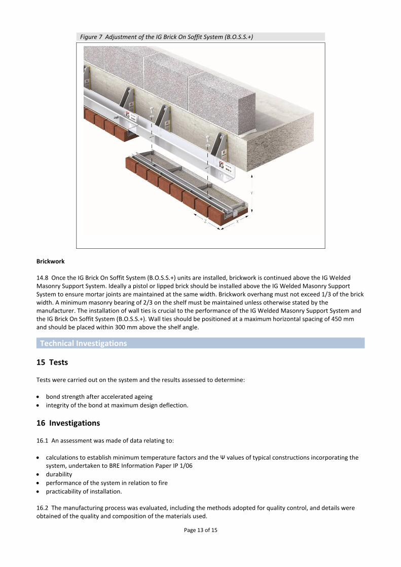
14.7 Lateral adjustment (Z) is achieved by utilizing the channel in the IG Brick On Soffit System (B.O.S.S.+) unit. The unit can be moved +/-25mm left or right on the fixed IG Welded Masonry Support System. Vertical adjustment (Y) is achieved by shimming between the unit and the underside of the IG Welded Masonry Support System. Maximum shimming in this location is 6 mm. Horizontal adjustment (X) is achieved by the utilizing slotted hole in the masonry support shelf. Adjustment provided is +/-15mm (see Figure 7).
Page 13 of 15
Figure 7 Adjustment of the IG Brick On Soffit System (B.O.S.S.+)
Brickwork 14.8 Once the IG Brick On Soffit System (B.O.S.S.+) units are installed, brickwork is continued above the IG Welded Masonry Support System. Ideally a pistol or lipped brick should be installed above the IG Welded Masonry Support System to ensure mortar joints are maintained at the same width. Brickwork overhang must not exceed 1/3 of the brick width. A minimum masonry bearing of 2/3 on the shelf must be maintained unless otherwise stated by the manufacturer. The installation of wall ties is crucial to the performance of the IG Welded Masonry Support System and the IG Brick On Soffit System (B.O.S.S.+). Wall ties should be positioned at a maximum horizontal spacing of 450 mm and should be placed within 300 mm above the shelf angle.
Technical Investigations
15 Tests Tests were carried out on the system and the results assessed to determine:
bond strength after accelerated ageing
integrity of the bond at maximum design deflection.
16 Investigations 16.1 An assessment was made of data relating to:
calculations to establish minimum temperature factors and the Ψ values of typical constructions incorporating the system, undertaken to BRE Information Paper IP 1/06
durability
performance of the system in relation to fire
practicability of installation. 16.2 The manufacturing process was evaluated, including the methods adopted for quality control, and details were obtained of the quality and composition of the materials used.
Page 14 of 15
Bibliography BRE Information Paper IP 1/06 Assessing the effects of thermal bridging at junctions and around openings BRE Report BR 497 : 2007 Conventions for calculating linear thermal transmittance and temperature factors BS EN 771-1 : 2011 + A1 : 2015 Specification for masonry units — Clay masonry units BS EN 771-2 : 2011 + A1 : 2015 Specification for masonry units — Calcium silicate masonry units BS EN 1990 : 2002 Eurocode — Basis of structural design BS EN 1991-1-4 : 2005 Eurocode 1 : Actions on structures — General actions — Wind actions BS EN 1993-1-2 : 2005 Eurocode 3. Design of steel structures. General rules. Structural fire design NA to BS EN 1993-1-2 : 2005 UK National Annex to Eurocode 3. Design of steel structures. General rules. Structural fire design BS EN 1996-1-1 : 2005 + A1 : 2012 Eurocode 6: Design of masonry structures — General rules for reinforced and unreinforced masonry structures NA to BS EN 1996-1-1 : 2005 + A1 : 2012 UK National Annex to Eurocode 6: Design of masonry structures — General rules for reinforced and unreinforced masonry structures BS EN 1996-1-2 : 2005 Eurocode 6: Design of masonry structures — General rules — Structural fire design NA to BS EN 1996-1-2 : 2005 UK National Annex to Eurocode 6: Design of masonry structures — General rules — Structural fire design BS EN 10028-7 : 2016 Flat products made of steels for pressure purposes — Stainless steels EN 12467 : 2012 + A2 : 2018 Fibre-cement flat sheets. Product specification and test methods BS EN ISO 9001 : 2015 Quality management systems — Requirements BS EN ISO 10211 : 2017 Thermal bridges in building construction — Heat flows and surface temperatures — Detailed calculations BS EN ISO 14001 : 2015 Environmental management systems — Requirements with guidance for use
PD 6697 : 2010 Recommendations for the design of masonry structures to BS EN 1996‑1‑1 and BS EN 1996‑2
Page 15 of 15
Conditions of Certification
17 Conditions 17.1 This Certificate:
relates only to the product/system that is named and described on the front page
is issued only to the company, firm, organisation or person named on the front page – no other company, firm, organisation or person may hold or claim that this Certificate has been issued to them
is valid only within the UK
has to be read, considered and used as a whole document – it may be misleading and will be incomplete to be selective
is copyright of the BBA
is subject to English Law. 17.2 Publications, documents, specifications, legislation, regulations, standards and the like referenced in this Certificate are those that were current and/or deemed relevant by the BBA at the date of issue or reissue of this Certificate. 17.3 This Certificate will remain valid for an unlimited period provided that the product/system and its manufacture and/or fabrication, including all related and relevant parts and processes thereof:
are maintained at or above the levels which have been assessed and found to be satisfactory by the BBA
continue to be checked as and when deemed appropriate by the BBA under arrangements that it will determine
are reviewed by the BBA as and when it considers appropriate. 17.4 The BBA has used due skill, care and diligence in preparing this Certificate, but no warranty is provided. 17.5 In issuing this Certificate the BBA is not responsible and is excluded from any liability to any company, firm, organisation or person, for any matters arising directly or indirectly from:
the presence or absence of any patent, intellectual property or similar rights subsisting in the product/system or any other product/system
the right of the Certificate holder to manufacture, supply, install, maintain or market the product/system
actual installations of the product/system, including their nature, design, methods, performance, workmanship and maintenance
any works and constructions in which the product/system is installed, including their nature, design, methods, performance, workmanship and maintenance
any loss or damage, including personal injury, howsoever caused by the product/system, including its manufacture, supply, installation, use, maintenance and removal
any claims by the manufacturer relating to CE marking. 17.6 Any information relating to the manufacture, supply, installation, use, maintenance and removal of this product/system which is contained or referred to in this Certificate is the minimum required to be met when the product/system is manufactured, supplied, installed, used, maintained and removed. It does not purport in any way to restate the requirements of the Health and Safety at Work etc. Act 1974, or of any other statutory, common law or other duty which may exist at the date of issue or reissue of this Certificate; nor is conformity with such information to be taken as satisfying the requirements of the 1974 Act or of any statutory, common law or other duty of care.
British Board of Agrément Bucknalls Lane Watford Herts WD25 9BA