Mass Charger MASS 24/50-2; 24/75; 24/75 (120V); 24/100; 3-24/100; 48/25; 48/50 FULLY AUTOMATIC BATTERY CHARGER USER AND INSTALLATION MANUAL 10000001888/02 To download this manual in other languages, please visit our website: www.mastervolt.com
Transcript
Mass Charger MASS 24/50-2; 24/75; 24/75 (120V);
24/100; 3-24/100; 48/25; 48/50
FULLY AUTOMATIC BATTERY CHARGER
USER AND INSTALLATION MANUAL
10000001888/02
To download this manual in other languages, please
visit our website: www.mastervolt.com
2 Mass Charger 24/50-2, 24/75, 24/75 (120V), 24/100, 3-24/100, 48/25, 48/50 – User and Installation Manual
TABLE OF CONTENTS
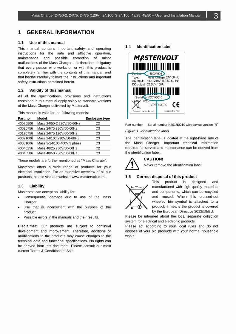
1 GENERAL INFORMATION ........................................ 3 1.1 Use of this manual .............................................. 3 1.2 Validity of this manual ......................................... 3 1.4 Disclaimer ........................................................... 3 1.5 Identification label ............................................... 3 1.6 Correct disposal of this product .......................... 3
2 SAFETY INSTRUCTIONS .......................................... 4 2.1 General ............................................................... 4 2.2 Explosive gases .................................................. 4 2.3 Warnings regarding the use of batteries ............. 4 2.4 Warning regarding life support applications ........ 5 2.5 Guarantee specifications .................................... 5
3 PRODUCT DESCRIPTION ......................................... 6 3.1 The 3-step+ charge process ............................... 6 3.2 Dimensions ......................................................... 6
4.3.1 AC wiring ................................................. 7 4.3.2 AC safety grounding ................................ 7 4.3.3 DC wiring ................................................. 8 4.3.4 Connection of main batteries ................... 8
4.4 Battery capacity .................................................. 8 4.5 Battery isolator .................................................... 8 4.6 Connection of second battery (3A output) .......... 8 4.7 Temperature sensor ........................................... 8 4.8 Voltage sense ..................................................... 9 4.9 Alarm function ..................................................... 9
4.9.1 Standard alarm mode .............................. 9 4.9.2 DC alarm mode ....................................... 9
4.10 RJ12 splitter for enclosure C2 ............................. 9 4.11 Overview connection compartment ................... 10 4.12 Things you need ................................................ 10 4.13 Connection ........................................................ 11 4.14 Installation step-by-step..................................... 12 4.15 Commissioning after installation ........................ 13
4.15.1 General .................................................. 13 4.15.2 MasterBus .............................................. 13
4.16 Decommissioning .............................................. 13 4.17 Storage and transportation ................................ 13
6 OPERATION ............................................................. 15 6.1 Switching on/off ................................................. 15 6.2 Reset the Mass Charger.................................... 15 6.3 Equalize mode ................................................... 15 6.4 LED indicators ................................................... 15
7 MASTERBUS ............................................................ 16 7.1 About MasterBus ............................................... 16 7.2 Event based commands .................................... 16 7.3 How to set up a MasterBus network .................. 16 7.4 MasterBus Settings ........................................... 16
Mass Charger 24/50-2, 24/75, 24/75 (120V), 24/100, 3-24/100, 48/25, 48/50 – User and Installation Manual
9
Figure 3. Temperature compensated charging
4.8 Voltage sense
If required, DC cable losses can be compensated by using
the sense function. This will shorten the charge time.
1. Use 0,75mm2, preferably red and black wire and
secure these with fuses of 2A slow blow.
2. Connect the wires with the two upper terminals of the
green connector at the right side of the cabinet (see
Figure 4 on page 10). Pay extra attention to the
polarity of the wires, red on +S and black on -S.
3. Now connect the other side of the wires: black on the
minus of the battery and red on the plus of the battery.
4.9 Alarm function
To control external equipment, the charger is equipped
with a potential free contacts alarm relay; see Figure 4 on
page 10. The alarm function has two modes: standard
(factory setting) and DC alarm mode (continuous mode).
The maximum switch current of the relay is 1A. Exceeding
the setpoints will activate the alarm (see page 17).
4.9.1 Standard alarm mode
In this mode the relay responds to all fault conditions that
the Mass Charger can detect such as: no AC input
voltage, low DC voltage, voltage sense failure,
temperature sense failure.
4.9.2 DC alarm mode
To enable this mode a DIP switch setting needs to be
changed (switch 1 and 2 at ON). The alarm now works as
a DC alarm and responds to the battery voltage only.
Note: In the DC alarm mode the electronics stay active
permanently and drain a very small current of
±25mA, also when the Mass Charger is switched
off.
4.10 RJ12 splitter for enclosure C2
The RJ12 connector (QRS232 communication port) can
be used to connect the battery temperature sensor or the
remote panel (not included). Use a RJ12-splitter to
connect both at the same time (not included).
Charg
e v
oltage (
V)
Battery temperature (°C)
10 Mass Charger 24/50-2, 24/75, 24/75 (120V), 24/100, 3-24/100, 48/25, 48/50 – User and Installation Manual
4.11 Overview connection compartment
C2
EN
CL
OS
UR
E
1 Screw terminals AC input: L1, N, PE
(24/100-3ph: L1, L2, L3, PE)
2 Earth stud
3 MasterBus connector
4 MasterBus connector
5 Output (battery) positive connector
(maximum 3A)
6 RS232/Temperature sensor connector
7 Analog/Temperature sensor connector
8 Output (battery) positive connector
9 Output (battery) negative connector
10 Voltage sense/ potential free alarm
contact
C3
EN
CL
OS
UR
E
Figure 4. Overview connections Mass Charger
4.12 Things you need
Make sure you have all the parts you need to install the Mass Charger:
Product Quantity
Mass Charger (included) 1
Battery temperature sensor with cable and plug (included) 1
DC cable to connect the positive DC connection (+) of the Mass Charger to the positive pole of the DC
distribution; for specifications see section 4.3.3 on page 7
1
DC cable to connect the negative DC connection (–) of the Mass Charger to the negative pole of the DC
distribution; for specifications see section 4.3.3 on page 7
1
DC fuse holder with a DC fuse, to be integrated in the positive DC cable 1
Screws/bolts (Ø 6mm) (with plugs) to mount the cabinet to a surface. Use mounting materials which are suitable
to carry the weight of the Mass Charger
4
AC cable* to connect the AC input to an external power source (e.g. a shore connection or a generator set) 1
Batteries. See section 4.4 on page 8 for recommended capacity X
Appropriate and reliable cable terminals, cable lugs, battery terminals and cord end terminals X
* Double insulated three-wire cable with wire colours according to the locally applicable regulations. The applicable length and
wire diameter depend on the electrical installation (see section 4.3.1 on page 7).
We recommend as a minimum tool kit:
Socket wrench 13mm to fix the DC input (battery) cables
Flat blade screw driver 1.0 x 4.0mm to fix the screw terminals
Tools to fix the screws/bolts (Ø 6mm) with plugs to mount the cabinets to a surface
Philips screw driver to open the connection area of the Mass Charger
2mm flat blade screw driver for the sense terminal (see Figure 4, point 10).
Mass Charger 24/50-2, 24/75, 24/75 (120V), 24/100, 3-24/100, 48/25, 48/50 – User and Installation Manual
11
4.13 Connection
WARNING
Let installation work be done by a licensed
electrician. Before beginning with the
connection of the wiring, make the AC
distribution as well as the DC distribution
voltage free.
CAUTION!
Too-thin cables and/or loose connections can cause
dangerous overheating of the cables and/or terminals.
Therefore tighten all connections well, in order to limit
transition resistance as far as possible. Use cables of
the correct size.
Note: If the battery temperature remains within
15-25°C, the battery temperature sensor is
optional.
Note: The Mass Charger supports MasterBus and RS 232
compatible remote control panels.
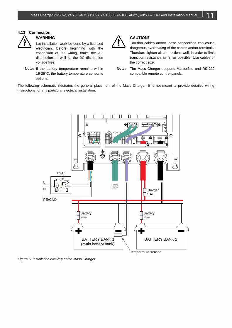
The following schematic illustrates the general placement of the Mass Charger. It is not meant to provide detailed wiring
instructions for any particular electrical installation.
Figure 5. Installation drawing of the Mass Charger
BATTERY BANK 1
(main battery bank)
Temperature sensor
BATTERY BANK 2
Battery
fuse
Battery
fuse
Charger
fuse
L
N
PE/GND
RCD
12 Mass Charger 24/50-2, 24/75, 24/75 (120V), 24/100, 3-24/100, 48/25, 48/50 – User and Installation Manual
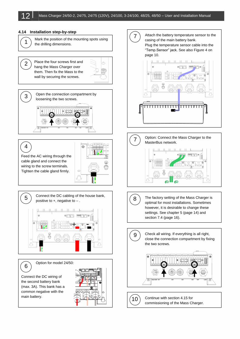
4.14 Installation step-by-step
1 Mark the position of the mounting spots using
the drilling dimensions.
2 Place the four screws first and
hang the Mass Charger over
them. Then fix the Mass to the
wall by securing the screws.
3 Open the connection compartment by
loosening the two screws.
4
Feed the AC wiring through the
cable gland and connect the
wiring to the screw terminals.
Tighten the cable gland firmly.
5 Connect the DC cabling of the house bank,
positive to +, negative to – .
+ -
+ - 6
Option for model 24/50:
Connect the DC wiring of
the second battery bank
(max. 3A). This bank has a
common negative with the
main battery.
7 Attach the battery temperature sensor to the
casing of the main battery bank.
Plug the temperature sensor cable into the
“Temp.Sensor” jack. See also Figure 4 on
page 10.
7 Option: Connect the Mass Charger to the
MasterBus network.
8 The factory setting of the Mass Charger is
optimal for most installations. Sometimes
however, it is desirable to change these
settings. See chapter 5 (page 14) and
section 7.4 (page 16).
9 Check all wiring. If everything is all right,
close the connection compartment by fixing
the two screws.
10 Continue with section 4.15 for
commissioning of the Mass Charger.
Mass Charger 24/50-2, 24/75, 24/75 (120V), 24/100, 3-24/100, 48/25, 48/50 – User and Installation Manual
13
4.15 Commissioning after installation
Note: When your Mass Charger is not new, you have to
take into account that former users may have
changed the settings. Reset the Mass Charger to
factory settings when there is any doubt (see
section 7.4 on page 16).
4.15.1 General
The factory settings of the Mass Charger are optimal for
most installations. With some applications however, it is
desirable to change these settings. Therefore several
adjustments can be made. See chapters 5 and 7.4.
Note: The DIP switches must be adjusted prior to
commissioning; all other settings can only be
configured after commissioning.
CAUTION! Check the polarity of all wiring before
commissioning: positive connected to positive
(red cables), negative connected to negative
(black cables).
If all wiring is OK, place the DC fuse(s) of the DC
distribution to connect the batteries to the Mass Charger.
WARNING When placing this fuse, a spark can occur,
caused by the capacitors used in the Mass
Charger.
Now the Mass Charger is ready for operation. After
switching on the AC power supply the Mass Charger will
initiate the charging process.
4.15.2 MasterBus
Adjustment of the settings of the Mass Charger can be
made by means of DIP switches or via the MasterBus
network (by means of an USB interface connected to a PC
with MasterAdjust software). Some settings can only be
changed via the MasterBus interface. See section 7.4 on
page 16 for an overview of all available MasterBus
settings.
4.16 Decommissioning
If it is necessary to put the Mass Charger out of operation,
follow the instructions in order of succession as described
below:
1 Switch the Mass Charger to off.
2 Remove the DC fuse(s) of the DC distribution and/or
disconnect the batteries.
3 Remove the AC fuse(s) of the AC input and/or
disconnect the AC mains.
4 Open the connection compartment of the Mass
Charger.
5 Check with a suitable voltage meter whether the
inputs and the outputs of the Mass Charger are
voltage free.
6 Disconnect all wiring.
Now the Mass Charger can be demounted in a safe way.
4.17 Storage and transportation
When not installed, store the Mass Charger in the original
packing, in a dry and dust free environment.
Always use the original packing for transportation. Contact
your local Mastervolt Service Centre for further details if
you want to return the apparatus for repair.
14 Mass Charger 24/50-2, 24/75, 24/75 (120V), 24/100, 3-24/100, 48/25, 48/50 – User and Installation Manual
5 DIP SWITCH SETTINGS
The Mass Charger settings can be adjusted in two ways:
By means of DIP switches;
Via the MasterBus network (by means of a remote
control panel or an interface connected to a PC with
MasterAdjust software); see section 7.4 on page 16.
Note: Once a DIP switch has been set to On, MasterBus
presets are disabled but people can still change the
settings!
CAUTION! Invalid settings of the Mass Charger can cause
serious damage to your batteries and/or the
connected load! Adjustments of settings may be
undertaken by qualified personnel only!
5.1 DIP switch operation
The Mass Charger has six DIP switches. These switches
are operated by flipping the levers to the other position,
using a small screw driver.
Figure 6. DIP switches
5.2 DIP switch functions
See the table for the functional overview of the DIP
switches (Switch 5 and 6 are reserved for future use).
Force Float (DIP switch 1)
For special applications a fixed charge voltage can be
required. The battery charger allows you to change the 3-
step+ charge program to a single stage program by
activating the function "Force Float", switching DIP switch
1 to "ON".
The charge voltage will be fixed at 26.5V (24V charger) or
53V for a 48V charger.
Traction setting (DIP switch 2)
Setting for traction charging: +0.7/1.4V during bulk and
+0.4/0.8V in absorption for 24/48V batteries.
Gel/AGM batteries (DIP switch 3)
Some Gel/AGM batteries need a higher float voltage for
optimal charge. Changing the float voltage can be done by
setting DIP switch 3 to "ON". The float voltage will
increase to 27.6V (24V charger) or 55.2V for a 48V
charger.
Diode setting (DIP switch 4)
Setting for +0.6V voltage compensation in case a battery
isolator is used.
DIP SWITCH 4 3 2 1
Standard 0 0 0 0
Diode 1 0 0 0
Gel/AGM 0 1 0 0
Diode + Gel/AGM 1 1 0 0
Traction 0 0 1 0
Traction + Diode 1 0 1 0
ContMon + Traction 0 1 1 0
ContMon + Traction + Diode 1 1 1 0
ForceFloat 0 0 0 1
ForceFloat + Diode 1 0 0 1
ForceFloat + Gel/AGM 0 1 0 1
ForceFloat + Diode + Gel/AGM
1 1 0 1
ContMon 0 0 1 1
ContMon + Diode 1 0 1 1
ContMon + Gel 0 1 1 1
ContMon + Diode + Gel/AGM 1 1 1 1
1 = On; 0 = Off
ContMon: Continuous monitor mode. MasterBus,
RS232 and DC alarm stay functioning at
mains failure. Remote stays functioning if it
has its own power source.
Diode: Diode compensation on (+0.6V)
Gel/AGM: Gel/AGM compensation on (during float
+1.1V or 2.2V)
Traction Traction charging (+0.7 or 1.4V during bulk
and +0.4 or 0.8V in absorption).
Force float: One step charge program with fixed float
voltage.
Mass Charger 24/50-2, 24/75, 24/75 (120V), 24/100, 3-24/100, 48/25, 48/50 – User and Installation Manual
15
6 OPERATION
6.1 Switching on/off
Activate the Mass Charger by switching the main switch to
the on position. When no error is present, the charger LED
illuminates green and the Mass Charger starts charging.
Move the switch to the off position to switch off the Mass
Charger!
6.2 Reset the Mass Charger
Set the main switch to off. 1.
Switch on again. 2.
The Mass Charger automatically resumes operation in
Bulk stage after it was disconnected from an AC source.
6.3 Equalize mode
An equalizing charge can be necessary after very deep
discharges and/or inadequate charges. This has to be
carried out according to the specifications of the battery
manufacturer.
WARNING!
Equalization is ONLY applicable for flooded
batteries and will damage Gel/AGM/Spiral type
batteries!
Incorrect use of the equalize mode may lead to hazardous
situations. During equalizing the batteries are brought into
the gas state and permitted load voltages may be
exceeded (refer to Figure 10 on page 23 for
characteristics). For these reasons the equalizing mode
should only be used by trained technical engineers.
The equalizing mode can only be started when the Mass
Charger is in float operation. To start the equalize mode,
select Equalize in the MasterBus device settings (see
section 7.4 on page 16).
6.4 LED indicators
Figure 7. Front panel of the battery charger
During normal operation the charger LED (6) is green.
When all charge process status LEDs (1 to 5) are on, the
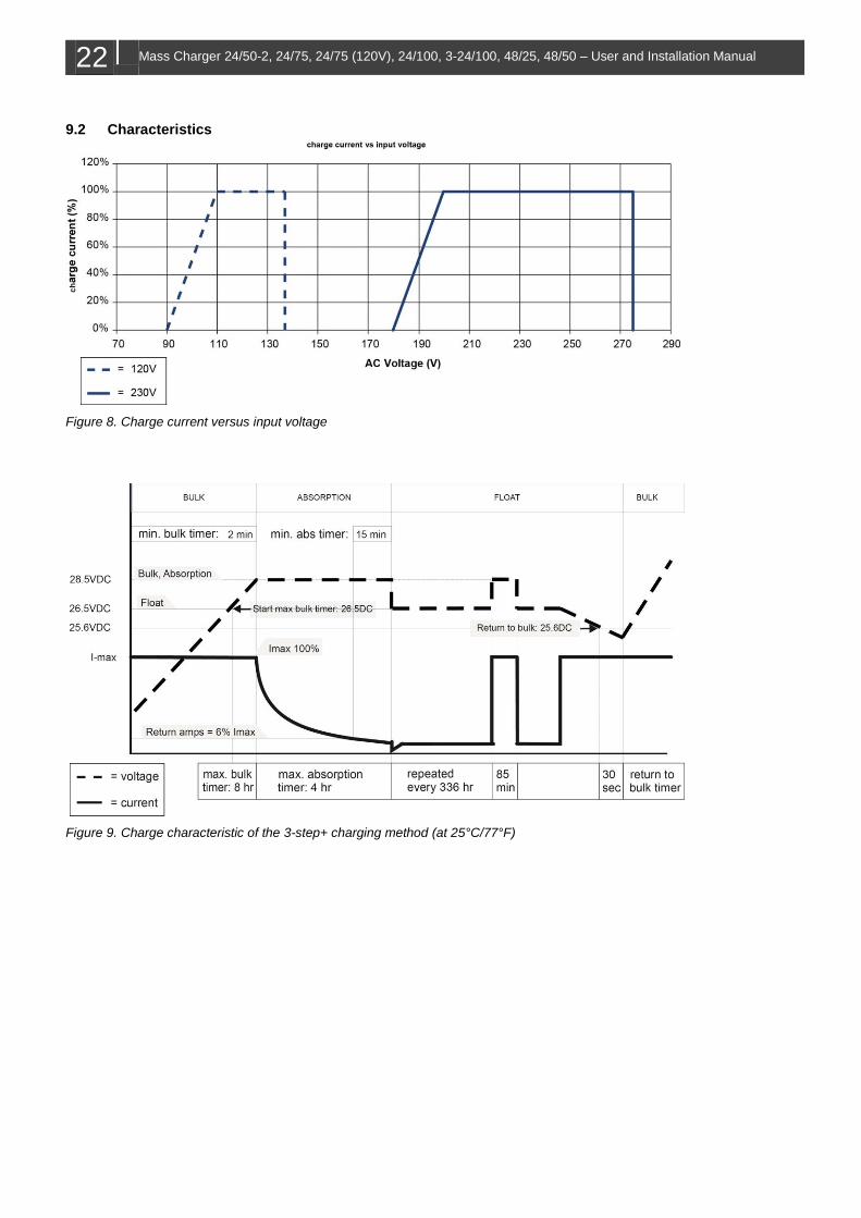
battery is fully charged. For details refer to Figure 9 on
page 22.
1…5 Status LEDs charge process
6 Charger status LED:
˗ Green = on
˗ Off = off
˗ Red = fault condition:
+: Battery sense error
+: Charger temperature too high
+: Short circuit indication, charger will reduce
the charge current to 25%
+: DC error, DC voltage too low or too high
+: Temperature sense error
7 Status LED MasterBus communication:
˗ Green = MasterBus communication
˗ Off = no MasterBus communication
8 Main or on/off switch
9...13 Status LEDs charge current
13 5
4
3
2
1
7
6
8
9
10
11
12
16 Mass Charger 24/50-2, 24/75, 24/75 (120V), 24/100, 3-24/100, 48/25, 48/50 – User and Installation Manual
7 MASTERBUS
7.1 About MasterBus
All devices that are suitable for MasterBus are
marked with the MasterBus symbol.
MasterBus is a CAN based, fully decentralized data
network for communication between Mastervolt devices.
MasterBus is used as power management system for all
connected equipment, such as the inverter, battery
charger, generator and many more.
Every device that is compatible with MasterBus is
equipped with two data ports. The devices are simply
chained together, forming a local data network. Monitoring
panels such as the EasyView 5 can be used for monitoring
and control of all connected MasterBus equipment.
CAUTION!
Never connect a non-MasterBus device to the
MasterBus network directly! This will damage
all connected MasterBus devices.
7.2 Event based commands
With MasterBus a device can be programmed to initiate an
action at another connected device. This is done by
means of event based commands.
7.3 How to set up a MasterBus network
Connections between the devices are made by
standard straight MasterBus cables. Mastervolt can
supply these cables.
Up to 63 MasterBus devices can be connected
together.
MasterBus needs a terminator on both ends of the
network.
The electric power for the network comes from the
connected devices according to the rule:
1 powering/3 non powering.
Do not make ring networks.
Do not make T-connections in the network.
7.4 MasterBus Settings
Meaning Factory setting Adjustable range
Device settings
Language Language that is displayed on a monitoring device connected to the MasterBus.
English EN, NL, DE, FR, ES, IT
Name Name for the Mass Charger. CHG Mass+type* 0-12 characters
Device Device name recognized by MasterBus. Mass Charger -
Battery name Name for the main battery bank. House Bank 0-16 characters
Factory settings Option to reset the Mass Charger to default settings.
Not reset Not reset, reset
Presets
Diode compensate Option for charger diode +0.6V voltage compensation. If it is enabled, the compensation value is adjustable.
Disabled Disabled,
Enabled: 0-2.50V
Forced float Option for Forced Float or constant voltage charging. If it is enabled, Forced Float voltage is adjustable.
Disabled Disabled, Enabled
Continuous mode Option to keep MasterBus powered by the battery when the Mass Charger is disabled.
Disabled Disabled, Enabled
Gel/AGM Gel/ AGM settings option. It includes fully adjustable Bulk, Absorption and Float settings.
Disabled Disabled, Enabled
Traction Traction settings option. See Traction settings. Disabled Disabled, Enabled
NiCad NiCad settings option See NiCad settings. Disabled Disabled, Enabled
Li-ion Li-ion settings option. See MLI settings. Disabled Disabled, Enabled
Equalize Option to enable Equalizing. Shows only when no other battery type has been selected. Warning: Equalize is suitable for flooded batteries only! Do not use Equalize for other battery types!
Disabled Disabled, Enabled
Mass Charger 24/50-2, 24/75, 24/75 (120V), 24/100, 3-24/100, 48/25, 48/50 – User and Installation Manual
17
Meaning Factory setting Adjustable range
General
Max. current Maximum charge current, adjustable model
dependent.
(Max current)* 0 – Imax*
Temp.
compensate
Charge voltage compensation for temperature
(V/°C).
-0.060/-0.120V/°C -1.000 – 1.000V/°C
Bulk
Bulk voltage Bulk voltage 28.50/57.00V 16.00-32.00/ 32.00-64.00V
Max. bulk time Maximum bulk timer 480 min 0-600 min
Min bulk time Minimum bulk timer 2 min 0-600 min
Start bulk time Voltage at which to start the bulk timer. 27.60/55.20V 16.00-32.00/ 32.00-64.00V
Bulk ret. volt. Return to Bulk voltage 25.60/51.20V 16.00-32.00/ 32.00-64.00V
Bulk ret. time Adjustable Return to Bulk time after the Return to
Bulk voltage has been reached.
30 sec 0-255 sec
Absorption
Abs. voltage Absorption voltage 28.50/ 57.00V 16.00-32.00/ 32.00-64.00V
Max absorption Maximum absorption timer 240 min 0-600 min
Min absorp. time Minimum absorption timer 15 min 0-180 min
Return amps Return to Float current (in A) 6.0 %*I max 0-25% * I max
Float
Float voltage Float voltage 26.50/53.00V 16.00-32.00/ 32.00-64.00V
Equalize voltage Equalize voltage 31.00/62.00V 16.00-32.00/ 32.00-64.00V
Equalize time Equalize time 360 min 0-600 min
Alarm set points
DC Alrm high on Alarm DC High on 32.00/64.00V 16.00-32.00/ 32.00-64.00V
DC Alrm high off Alarm DC High off 30.00/60.00V 16.00-32.00/ 32.00-64.00V
DC Alrm low on Alarm DC low on 20.00/40.00V 16.00-32.00/ 32.00-64.00V
DC Alrm low off Alarm DC low off 22.00/44.00V 16.00-32.00/ 32.00-64.00V
DC Alrm delay Alarm delay time 30 sec 0-255 sec
Traction settings
Bulk voltage Bulk voltage 29.20/58.40V (read only)
Max bulk time Maximum bulk time 360 min (read only)
Min bulk time Minimum bulk time 4 min (read only)
Start bulk time Start bulk time 27.60/55.20V (read only)
Bulk ret. volt. Bulk return voltage 25.60/51.20V (read only)
Bulk return time Bulk return time 30 sec (read only)
Abs. voltage Absorption voltage 28.90/57.80V (read only)
Max absorp. time Maximum absorption time 480 min (read only)
Min absorp. time Minimum absorption time 15 min (read only)
Return amps Return to Bulk current (in A) 6.0 %*I max (read only)
Float voltage Traction float voltage 26.50/53.00V (read only)
NiCad settings
Bulk voltage Bulk voltage 29.00/58.00V (read only)
Max bulk time Maximum bulk time 480 min (read only)
Min bulk time Minimum bulk time 2 min (read only)
Start bulk time Start bulk time 26.50/53.00V (read only)
Bulk ret. volt. Bulk return voltage 10.00/20.00/40.00V (read only)
Bulk return time Bulk return time 30 sec (read only)
Abs. voltage Absorption voltage 29.00/58.00V (read only)
Max absorp. time Maximum absorption time 480 min (read only)
Min absorp. time Minimum absorption time 15 min (read only)
Return amps Return to Bulk current (in A) 6.0 %*I max (read only)
Float NiCad float voltage 26.00/52.00V (read only)
18 Mass Charger 24/50-2, 24/75, 24/75 (120V), 24/100, 3-24/100, 48/25, 48/50 – User and Installation Manual
Meaning Factory setting Adjustable range
MLI (Li-ion) settings
Bulk voltage Bulk voltage 28.50/57V (read only)
Max bulk time Maximum bulk time 480 min (read only)
Min bulk time Minimum bulk time 2 min (read only)
Start bulk time Start bulk time 26.50/53.00V (read only)
Bulk ret. volt. Bulk return voltage 26.30/52.60V (read only)
Bulk return time Bulk return time 240 sec (read only)
Abs. voltage Absorption voltage 28.50/57V (read only)
Max absorp. time Maximum absorption time 240 min (read only)
Min absorp. time Minimum absorption time 15 min (read only)
Return amps Return to Bulk current (in A) 6.0 %*I max (read only)
Forced Float LI-ion forced float voltage 27/54V (read only)
* Depending on model
Events
Event x source Event-based command.
Mass Charger event that should result in an action by
another device on the MasterBus network.
Disabled See Event source list.
Event x target Select a connected MasterBus device that should take
action due to a Mass Charger event.
Select… Selectable targets are
system dependent.
Event x
command
Action to be taken by the target device. Select… See command list in
selected device manual
Event x data Data is linked to the command.
On changes the status to On at the first signal.
Off changes the status to Off at the first signal.
Copy lets the status follow the input.
Copy Invert lets the status follow the opposite of the input
Toggle changes the status at the 1st signal and back at the
2nd
signal. It is used in combination with a pulse switch.
Off Off, On, Copy,
Copy Invert, Toggle.
Event x+1 The next event appears after enabling Event x. Disabled See Event x.
Mass Charger event source list (Mass Charger as event source)
Charging Mass Charger state is On
Bulk Charge stage is Bulk
Absorption Charge stage is Absorption
Float Charge stage is Float
Failure Charger failure MasterBus alarm
CSI Charger Status Interface MasterBus alarm to generate an audible alarm at charger failure
Equalize Mass Charger is in Equalize mode
TC Error Battery temperature sensor error
Fan MasterBus signal for an external fan to start (at 50% load/50°C)
LED Bulk LED Bulk illuminates
LED 20-40 LED 2 illuminates (see Figure 7)
LED Abs LED Abs illuminates
LED 60-80 LED 4 illuminates (see Figure 7)
LED Float LED Float illuminates
LED Failure LED Failure illuminates
Mass Charger event target list (Mass Charger as event target)
Bulk Command to start the Bulk stage of charge
Absorption Command to start the Absorption stage of charge
Float Command to start the Float stage of charge
On/ Standby Command to switch on the Mass Charger
Mass Charger 24/50-2, 24/75, 24/75 (120V), 24/100, 3-24/100, 48/25, 48/50 – User and Installation Manual
19
8 TROUBLE SHOOTING
In case of a failure, the Mass Charger display shows an
error ‘code’ to help you find its source. See section 6.4
LED indicators, on page 15. If you cannot solve a problem
using the following fault finding table, contact your supplier
or Mastervolt. Make sure you have the part and serial
number at hand (See section 1.4, on page 3).
Malfunction Possible cause What to do
No output voltage and/or current
No AC input. Check AC wiring, check remote control panel.
AC input voltage too low (< 180VAC). Check input voltage, check generator.
AC input frequency out of range. Check input voltage, check generator.
Output voltage too low, charger supplies maximum current
Load that is connected to the batteries is larger than charger can supply.
Reduce load taken from the batteries.
Batteries not 100% charged. Measure battery voltage. After some time this will be higher.
Charge current too low Batteries almost fully charged. Nothing, this is normal when the battery is almost fully charged.
High ambient temperature. Nothing; if ambient temperature is more than 40°C the charge current is automatically reduced.
Low AC input voltage. At lower AC input voltages the charge current is reduced. See Figure 8 on page 22.
Check AC input voltage.
Batteries not fully charged
Charge current too low. See “Charge current too low”.
Current to load is too high. Reduce load taken from the batteries.
Charge time too short. Use a battery charger with higher capacity.
Battery temperature too low. Use the battery temperature sensor.
Defective or old battery. Check battery and replace if necessary.
Batteries are discharged too fast
Battery capacity reduced due to wastage or sulphation, stagnation.
Charge and recharge a few times, this might help.
Check battery and replace if necessary.
Batteries are too warm, gassing
Defective battery (short circuit in cell). Check battery and replace if necessary.
Battery temperature too high. Use the battery temperature sensor.
Charge voltage too high. Check settings (see section 7.4 on page 16).
20 Mass Charger 24/50-2, 24/75, 24/75 (120V), 24/100, 3-24/100, 48/25, 48/50 – User and Installation Manual