1 Mass transfer coefficient for drying of moist particulate in a bubbling fluidized bed Dr. Yassir T. Makkawi 1, and Prof. Raffaella Ocone 2 1 Chemical Engineering & Applied Chemistry, Aston University, Birmingham B4 7ET, UK 2 Chemical Engineering, Heriot-Watt University, Edinburgh EH14 4AS, UK Abstract Experiments on drying of moist particles by ambient air were carried out to measure the mass transfer coefficient in a bubbling fluidized bed. Fine glass beads of mean diameter 125 m were used as the bed material. Throughout the drying process, the dynamic material distribution was recorded by Electrical Capacitance Tomography (ECT) and the exit air condition was recorded by a temp/humidity probe. The ECT data were used to obtain qualitative and quantitative information on the bubble characteristics. The exit air moisture content was used to determine the water content in the bed. The measured overall mass transfer coefficient was in the range of 0.0145-0.021 m/s. A simple model based on the available correlations for bubble-cloud and cloud-dense interchange (two-region model) was used to predict the overall mass transfer coefficient. Comparison between the measured and predicted mass transfer coefficient have shown reasonable agreement with the measurements. The results were also used to determine the relative importance of the two transfer regions. Keywords: Bubbling fluidized bed; Electrical Capacitance Tomography; Mass Transfer Coefficient; Particulate drying Corresponding author: Tel +44 0)121 204 3398, E-mail: [email protected]
Transcript
1
Mass transfer coefficient for drying of moist particulate in a bubbling fluidized bed
Dr. Yassir T. Makkawi1, and Prof. Raffaella Ocone2
1 Chemical Engineering & Applied Chemistry, Aston University, Birmingham B4 7ET, UK
2 Chemical Engineering, Heriot-Watt University, Edinburgh EH14 4AS, UK
Abstract Experiments on drying of moist particles by ambient air were carried out to measure the mass
transfer coefficient in a bubbling fluidized bed. Fine glass beads of mean diameter 125 m were
used as the bed material. Throughout the drying process, the dynamic material distribution was
recorded by Electrical Capacitance Tomography (ECT) and the exit air condition was recorded
by a temp/humidity probe. The ECT data were used to obtain qualitative and quantitative
information on the bubble characteristics. The exit air moisture content was used to determine
the water content in the bed. The measured overall mass transfer coefficient was in the range of
0.0145-0.021 m/s. A simple model based on the available correlations for bubble-cloud and
cloud-dense interchange (two-region model) was used to predict the overall mass transfer
coefficient. Comparison between the measured and predicted mass transfer coefficient have
shown reasonable agreement with the measurements. The results were also used to determine
the relative importance of the two transfer regions.
Keywords: Bubbling fluidized bed; Electrical Capacitance Tomography; Mass Transfer Coefficient; Particulate drying
Corresponding author: Tel +44 0)121 204 3398, E-mail: [email protected]
2
1. Introduction
Bubbling fluidized bed technology is one of the most effective mean for interaction between solid
and gas flow, mainly due to its good mixing and high heat and mass transfer rate. When applied
to drying of non-porurs wetted solid particles, the water is drawn-off driven by the difference in
water concentration between the bubble phase and the surrounding phases. Different
mechanisms can regulate this process, depending on the bed hydrodynamics (i.e. bubbles
characteristics) and the water content in the bed. Therefore, the design of bubbling fluidized bed
dryer requires an understanding of the combined complexity in hydrodynamics and mass
transfer mechanism. Mass transfer in fluidized beds is generally known to be more complex than
heat transfer. In a gas-solid fluidized bed drier there are different phases which all contribute to
the removal of moisture from the wet particles. These are the bubble phase, its surrounding
cloud phase and the dense annular phase. Thus, in experimental determination of the overall
mass transfer coefficient, one must have in hand detailed quantitative data on the bubble
characteristics, as well as the drying rate.
The most widely used mass transfer model of Kunii and Levenspiel [1] expresses the overall
mass transfer in a bubbling bed in terms of the cloud-bubble interchange and dense-cloud
interchange. The first mechanism is assumed to arise from the contribution of bubble
“throughflow” (i.e. circulating gas from the cloud phase and in and out of the bubble) in addition
to the diffusion from a thin cloud layer into the bubble. The second mechanism is assumed to
arise only from diffusion between the dense phase and the cloud boundary. For particles of
about 500 m, some researchers assume that the transfer is of a purely diffusional nature, and
thus neglect the contribution of bubble throughflow. However, Walker [2] and Sit and Grace [3]
pointed out that, pure diffusional model may significantly underestimate, the overall mass
transfer coefficient. Kunii and Levenspiel [1] reported that the true overall mass transfer
coefficient may fall closer to either of the acting mechanisms depending on the operating
conditions (particle size, gas velocity, etc.). They suggested accounting for the first mechanism
by summing the diffusional and throughflow, and adding those to the second mechanism in a
similar fashion as for additive resistance.
Because of the growing interest on modelling as a tool for effective research and design,
researchers on bubbling fluidized bed drying or mass transfer in general are nowadays seeking
to validate or develop new mass transfer coefficient equations required for accurate prediction of
the process kinetics. Ciesielczyk and Iwanowski [4] presented a fluidized bed drying model
based on the interphase mass transfer coefficient. They incorporated Mori and Wen [5] model
3
for the bubble diameter into the mass transfer coefficient formulation of Kunii and Levenspiel [1]
to predict a generalized drying curve for solid particles in a bubbling bed. The results have
shown good agreement with the experimental measurement for group B particles of Geldart
classification. Kerkhof [6] discussed some modeling aspect of batch fluidized bed drying, where
Kunii and Levenspiel [1] mass transfer coefficient combined with particles internal diffusion
model was used to simulate the thermal degradation of life-science products. The study
suggested that the exchange between the bubble phase and the particles inside the bubble play
an important role in the drying process. Recently, Scala [7] experimentally studied the mass
transfer around a freely active particle in a dense fluidized bed of inert particles. He concluded
that the active particle only reside in the dense phase and never enters the bubble phase, hence
it has no direct contribution to the bubble-dense phase interchanges. This contradicting
observation confirms that despite the considerable effort on developing fluidized bed mass
transfer coefficients, there still remain uncertainties with respect to the assumptions used in
developing these coefficients.
The aim of this study was to measure the overall mass transfer coefficient in a conventional
bubbling fluidized bed dryer. The measurement was used for the validation of a simple predictive
model based on the available correlations and also to assess the various assumptions used in
developing these correlations. For this purpose, the drying rate and the corresponding mass
balance were calculated from the measurement of the drying air at outlet conditions. Information
on the bed hydrodynamics were obtained from Electrical Capacitance Tomography (ECT)
images.
2. Experimental
The primary objective of the experiment was to measure the mass transfer coefficient for a
drying process in a conventional bubbling fluidized bed. This required detailed knowledge of the
fluidized bed hydrodynamics and drying rate. For this purpose, non-porous wet solid particles of
glass beads were contained in a vertical column and fluidized using air at ambient temperature.
The fluidising air was virtually dry and obtained from a high-pressure compressor. An advanced
imaging ECT sensor was used to provide dynamic information on the fluidized bed material
distribution. The sensor was connected to a data acquisition unit and a computer. The air outlet
temperature and its relative humidity were recorded using a temperature/humidity probe. Since
the air condition at the inlet of the fluidization column was constant and completely independent
4
of the bubbling bed operating conditions, only one probe was installed at the freeboard (air exit).
The detailed experimental set-up is shown in Figure 1.
2.1. Equipment and materials
The fluidization was carried out in a cast acrylic column, 13.8 cm diameter and 150 cm high. The
column was transparent, thus allowing for direct visual observation. A PVC perforated gas
distributor with a total of 150 holes (~1.8% free area), was placed 24 cm above the column base.
The upstream piping was fitted with pressure regulator, moisture trap, valve and three parallel
rotamaters. A one-step valve was connected before the moisture trap and was used as the
upstream main flow controller. The particles used were ballotini (non-porous glass beads) with a
mean diameter of 125 m and a density of 2500 kg/m3 (Geldart A/B mixture). The detailed
physical properties of the particles are given in Tab. 1. Distilled water at ambient condition was
used to wet the particles. A variable speed granule shaker was utilised to produce the final
wetted mixture.
The Electrical Capacitance Tomography imaging system used (ECT from Process Tomography
Limited, Manchester, UK), consisted of two adjacent sensor rings each containing 8 electrode of
3.8 cm length. All electrodes were connected to the computer through a data acquisition module
(DAM 2000). The PC was equipped with custom communication hardware and software (ECT32)
that allow for online and off-line dynamic image display. The system is capable of taking cross-
sectional images of the bed at two adjacent levels simultaneously at 100 frames per second.
Further details about the ECT system used in this study and its application to fluidization
analysis can be found in Makkawi et al. [8] and Makkawi and Ocone [9].
The exit air quality was measured using a temperature and humidity probe (Type: Vaisala HMI
31, Vantaa, Finland, measuring range: 0-100% RH, -40-115 C°). The probe was hung by a
connecting wire inside the fluidized bed freeboard approximately 10 cm above the maximum
expanded bed height.
2.2. Procedure
The experimental procedure employed was completely non-intrusive. This is described in the
following steps in the order of their occurrence:
(a) A total weight of 4.5 kg of a dry ballotini mixture was placed in a granule shaker after
being wetted by distilled water. The shaker was firmly clamped and operated
5
continuously for at least 25 minutes to ensure an even distribution of water content.
Distilled water was used to eliminate any possible interference with the ECT signal (ECT
works for non-conducting materials only)
(b) The wetted particles were then loaded into the fluidization column. Prior to
commencement of drying, the ECT sensor was calibrated for two extreme cases. This
was carried out by sliding the ECT sensor up to the freeboard to calibrate for the empty
bed case, and down to the static bed area to calibrate for the packed bed case. It should
be mentioned that, because the water content was limited to a maximum of 45 ml (1%
moisture on dry solid weight basis), the possible changes in the particle/air permittivity
during the drying process would be negligible. Further details on the sensitivity of the
ECT system to moisture content in the fluidized bed dryer can be found in Chaplin and
Pugsley [10] and Chaplin et al. [11].
(c) The wet bed material was fluidized at the required air flow rate. This was carefully
adjusted to ensure the bed operation at the single bubble regime. The temperature and
relative humidity were recorded at 2 minutes intervals. Simultaneously, and at the 5
minutes intervals, a segment of 60 seconds ECT data were recorded. At the same time,
the expanded bed height during fluidization was obtained from visual observations.
(d) Finally, the drying rate was obtained from the measured air flow rate and
temperature/humidity data at inlet and outlet using psychometric charts and mass
balance calculations. The recorded ECT data were further processed off-line and loaded
into in-house developed MATLAB algorithm to estimate the bubble characteristics.
The above described procedure was repeated for the three different operating conditions
summarized in Tab. 2. To ensure data reproducibility, each operating condition was repeated
three times, making a total of nine experiment tests.
2.3. Measurement of mass transfer coefficient
Considering a section of the bed as shown in Figure 2, the overall mass transfer coefficient
between the bubble phase and the surrounding dense phase, dbk , can be defined by the
following rate equation:
)( bddbb
bbb CCk
V
S
dz
dCu
(1)
6
where bC is the water concentration in the bubble phase, dC is the concentration in the
surrounding dense phase, bu , bS and bV are characteristic features of the bubble representing
the rising velocity, the interphase area and the volume, respectively. For moisture-free inlet air,
Eq. 1 is subject to the following boundary conditions:
0)( airinb CC at 0z and boutb CC at Hz (2)
The bubble moisture content at the outlet boutC can be given by:
boutC = b
airinoutair
m
CCm )( (3)
where airm and bm are the mass flow rate of the fluidising air and bubbles respectively.
Because of the assumption that the bubbles rise much faster than the gas through the dense
phase and the inlet air was virtually dry, Eq. 3 reduces to:
airoutbout CC )( (4)
where airoutC )( is obtained from the measured temperature and humidity at the bubbling bed
surface.
For a spherical bubble, bb VS ratio appearing in Eq. 1 reduces to bd6 , where bd is the bubble
diameter. It should be mentioned that for a perforated distributor (such as the one used in this
experiment), coalescence of bubbles mainly takes place at a few centimetres above the
distributor, therefore, the entrance effects are neglected and the bubble characteristics are
assumed to be independent of height (this was confirmed from the ECT images).
Finally, assuming that the water concentration in the dense phase is uniform and remains
unchanged during the bubble rise ( bedwaterd wwC ) and integrating Eq. 1 from 0z to Hz ,
the mass transfer coefficient is obtained as follows:
d
boutdbbdb C
CC
H
udk ln
6 (5)
where bd , bu and H are the bubble diameter, the bubble velocity and the expanded bed height,
respectively.
(drying rate)
(bubble mass flow rate)
7
2.4. Measurement of bubble characteristics
Experimental determination of the overall mass transfer requires knowledge of the bubble
diameter and velocity (see Eq. 5). Using the ECT, the size and velocity of the bubbles (or ‘voids’)
in a gas-solid fluidized bed can be obtained. The distinct lowering of the solid fraction when the
bubble passes across the sensor area allows for identification of the bubble events in a given
time and space. The bubble velocity was then calculated from the delay time determined from a
detailed analysis of the signal produced by the two adjacent sensors, such that:
bb t
u
(6)
where 12 bbb ttt , 1bt and 2bt represent the time when the bubble peak passes through the
lower and upper level sensors respectively, and represents the distance between the centre
of the two sensors, which is 3.8 cm. The method is demonstrated for a typical ECT data in
Figure 3.
The bubble diameter was obtained from the ECT data of relative solid fraction at the moment of
bubble peak across the sensor cross-section. From this, the bed voidage fraction (the fraction
occupied by bubbles) was calculated as follows:
Ddb (7)
where P 1 is the bubble fraction, P is the relative solid fraction (i.e. packed bed: 1P ;
empty bed: 0P ) and D is the bed/column diameter. This procedure is demonstrated for a
typical ECT data in Figure 4.
Further details on the application of twin-plane ECT for the measurements of bubble
characteristics in fluidized bed can be found in Makkawi and Wright [12].
3. Theoretical Models
3.1. Estimation of mass transfer coefficient
In a bubbling fluidized bed, it is widely believed that mass transfer occurs in two distinct regions:
at the dense-cloud interface, dck , and at the cloud-bubble interface, cbk . The overall mass
transfer may be dense-cloud controlled; cloud-bubble controlled or equally controlled by the two
mechanisms depending on the operating conditions. The following theoretical formulations of
these acting mechanisms are mainly based on the following assumptions:
i. The fluidized bed operates at single bubble regime.
8
ii. The bubbles are spherically shaped.
iii. The bubble rise velocity is fast ( mfmfb Uu 5 ).
iv. The contribution of particles presence within the bubble is negligible.
v. The contribution of the gas flow through the dense phase is assumed to be negligible.
As evident from the tomographic analysis of the bubble characteristics, assumptions (i)-(iv) are
to a great extent a good representation of the actual bubbling behaviour.
Cloud-bubble interchange:
According to Davidson and Harrison [13], the mass transfer at the bubble-cloud interface arises
from two different contributions:
1. Diffusion across a limited thin layer where the mass transfer coefficient is estimated by:
25.0
5.0975.0
bcb d
gk D (8)
2. Convection contribution as a result of bubble throughflow, which consists of circulating gas
between the bubble and the cloud (leaving the bubbles from top and re-entering it from the
base as shown in Figure 5. Based on the analysis of Davidson and Harrison [13], Murray [14]
reported the following corrected equation for the contribution of bubble throughflow:
mfq Uk 25.0 (9)
Kunii and Levenspiel [1] recommended adding both acting mechanisms, thus the mass transfer
coefficient between the bubble-cloud is given by:
mfb
cb Ud
gk 25.0975.0
25.0
5.0
D (10)
Dense-cloud interchange:
Utilizing the Higbie penetration model [15], the mass transfer coefficient at the dense-cloud
interface is expressed in terms of the bubble-cloude exposure time and the effective diffusivity
as follows [16]:
5.04
tk mfe
dc D
(11)
9
where b
c
u
dt is the exposure time between the bubble and the cloud.
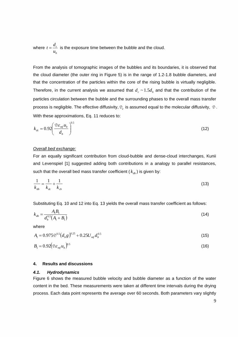
From the analysis of tomographic images of the bubbles and its boundaries, it is observed that
the cloud diameter (the outer ring in Figure 5) is in the range of 1.2-1.8 bubble diameters, and
that the concentration of the particles within the core of the rising bubble is virtually negligible.
Therefore, in the current analysis we assumed that bc dd 5.1~ and that the contribution of the
particles circulation between the bubble and the surrounding phases to the overall mass transfer
process is negligible. The effective diffusivity, eD is assumed equal to the molecular diffusivity, D .
With these approximations, Eq. 11 reduces to:
5.0
92.0
b
bmfdc d
uk
D (12)
Overall bed exchange:
For an equally significant contribution from cloud-bubble and dense-cloud interchanges, Kunii
and Levenspiel [1] suggested adding both contributions in a analogy to parallel resistances,
such that the overall bed mass transfer coefficient ( dbk ) is given by:
cbdcdb kkk
111 (13)
Substituting Eq. 10 and 12 into Eq. 13 yields the overall mass transfer coefficient as follows:
115.0
11
BAd
BAk
bdb (14)
where
5.025.05.01 25.0975.0 bmfb dUgdA D (15)
5.01 92.0 bmf uB D (16)
4. Results and discussions
4.1. Hydrodynamics
Figure 6 shows the measured bubble velocity and bubble diameter as a function of the water
content in the bed. These measurements were taken at different time intervals during the drying
process. Each data point represents the average over 60 seconds. Both parameters vary slightly
10
within a limited range. These hydrodynamic observations suggest that the bubble characteristics
almost remain independent of the water content, at least within the range of operation conditions
considered here. This is due to the fact that the initial water content in the bed was not
significant enough to cause considerable hydrodynamic changes.
Among the many available correlations, the following equations have been found to provide
good matches with the experimental measurements:
Bubble velocity [1]:
5.0711.0 bmfb gdUUu (17)
This a modified form of Davidson and Harrison [13] equation, where 75.0 and 312.3 cD
are correction factors suggested by Werther [17] and Hilligardt and Werther [18].
Bubble diameter [5]:
co
ocob Dz
n
DDzDd 3.0exp
347.03.0exp652.0
4.0 (18)
where
4.0
24
mf
co UU
DD
(19)
mfU used in Eqs 17 and 19 was given by:
mf
pmfgppmf
gdU
1150
32
(20)
For the operating condition given in Tab. 2, Eq. 20 gives mfU =0.065 m/s, which closely matches
the measured value of 0.062 m/s. Despite the fact that Eqs. 17-20 were all originally developed
for dry bed operations; they seem to provide a reasonable match with the experimental
measurements made here under wet bed condition (Figure 6). This is not surprising, since the
water content in the bed was relatively low as discussed above. The expanded bed height, used
in the experimental estimation of the overall mass transfer coefficient (Eq. 4), is shown in Figure
7. A clear gradual (but limited) increase in the bed expansion as the water is removed from the
bed can be noticed.
11
4.2. Drying rate
The drying rate curves for the three experiments conducted are shown in Figure 8. The curve
fitting is used to obtain the water content in the bed at various times. From Figure 8, it may be
concluded that the time of drying is directly proportional to the initial water content, and inversely
proportional to the drying air flow rate. For instance, at an air velocity of 0.47 m/s, this time was
reduced by half when reducing the initial water content from bedoC , =10% to bedoC , =5%, while at
the initial water content of bedoC , =10, this time was ~35% longer when reducing the air velocity
from 0.47 m/s to 0.33 m/s.
The water concentration in the bed as a function of the drying time is shown in Figure 9. This
was obtained from the integration of the drying curve function, tF , and subtracting it from the
initial water content, ow , such that:
t
ot dttFww0
(21)
4.3. Mass transfer coefficient
4.3.1 Experimental measurement
The measured overall mass transfer coefficient, dbk , as a function of the water concentration in
the bed is shown in Figure 10. The values of dbk falls within the range of 0.0145-0.021 m/s. It is
interesting to note that this range is close to the value one can obtain from the literature for the
mass transfer coefficient from a free water surface to an adjacent slow moving ambient air
stream (~0.015 m/s) [19].
4.3.2 Comparison with other experimental data
Walker [2] and Sit and Grace [3] measured the mass transfer coefficient in a two-dimensional
fluidized bed. The technique employed involves the injection of ozone-rich bubble into an air-
solid fluidized bed. Their experimental data for various particle sizes are compared with our
measurement in Figure 11. Taking into consideration the differences in the experimental set-up
and operating conditions, the agreement with our measurement appears satisfactory for the
particle size considered in this study.
12
4.3.3 Comparison with theoretical prediction
Figure 12 compares the measured mass transfer coefficient with the theoretical predictions
obtained from the formulations given in section 3.1. The boundaries for the overall mass transfer
coefficient are given by: (i) a model accounting for cloud-bubble contribution, dense-bubble
contribution as well as the bubble through flow contribution, giving the lower limit (Eq. 14) and (ii)
a model accounting for the cloud-bubble contribution only, giving the upper limit (Eq. 10). The
results also suggest that, within the operating conditions considered here, the drying may well be
represented by a purely diffusional model, controlled by either the resistance residing at the
dens-cloud interface, or the cloud-bubble interface.
Finally, Tab. 3 shows the numerical values of the various mass transfer contributions obtained
from Eqs 8-16. It is shown that the estimated diffusional resistances, as well as the contribution
from the bubble throughflow, are all of the same order of magnitude. Previously, Geldart [20]
argued that the bubble throughflow is not important for small particles and may be neglected.
According to our analysis, this may well be the case here. However, generalization of this
conclusion should be treated with caution especially when dealing with larger particles.
5. Conclusion
Mass transfer coefficient in a bubbling fluidized bed dryer has been experimentally determined.
This work is the first to utilise an ECT system for this purpose. The ECT allowed for
quantification of the bubble diameter and velocity, as well as providing new insight into the
bubble-cloud-dense boundaries.
The measured overall mass transfer coefficient was in the range of 0.045-0.021 m2/s. A simple
hydrodynamic and mass transfer model, based on the available correlations was used to predict
the mass transfer coefficient in a bubbling fluidized bed. Despite the complexity of the process,
and the number of assumption employed in this analysis, the model based on pure diffusional
mass transfer seems to provide satisfactory agreement with the experimental measurements.
This work set the seen for future experimental investigations to obtain a generalised correlation
for the mass transfer coefficient in fluidized bed dryer, particularly that utilizes the ECT or other
similar imaging techniques. Such a correlation is of vital importance for improved fluidized bed
dryer design and operation in its widest application. A comprehensive experimental program,
covering a wider range of operating conditions (particle size, gas velocity, water content,
porous/non-porous particles) is recommended.
13
Nomenclature
A [m2] column/bed cross-sectional area
11, BA [m1.5s-1] parameters defined in Eqs. 15, 16 respectively
bd CC , [-] water concentration in the dense and bubble phases respectively, kg/kg
Dd , [m] diameter
eDD, [m2s-1] molecular and effective diffusivity respectively
g [ms-2] gravity acceleration constant
H [m] expanded bed height
dbk [ms-1] overall mass transfer coefficient (between dense and bubble phases)
cbk [ms-1] mass transfer coefficient between cloud and bubble phases
dck [ms-1] mass transfer coefficient between dense and cloud phases
m [kgs-1] mass flow rate
P [-] relative solid fraction
S [m2] surface area
U [ms-1] superficial gas velocity
u [ms-1] velocity
V [(m3) volume
w [g] bed water content
z [m] axial coordinate
Greek symbols
[-] bed voidage
[-] bubble fraction
[kg.m-3] density
[m] distance between the centre of the two ECT sensors
p [-] particle sphericity
Subscripts
b bubble
c cloud
d dense
mf minimum fluidization
14
References
[1] D. Kunii, and O. Levenspiel, Fluidization Engineering. Second edition, Butterworth-Heinemann, Boston 1991. [2] B. V. Walker, Transaction Institute of Chemical Engineers 1975, 53, 225. [3] S.P. Sit, and J. R. Grace, Chemical Engineering Science 1978, 33, 1115. [4] W. Ciesielczyk and J. Iwanowski, Powder Technology 2006, 24, 1153. [5] S. Mori and C. Y. Wen, AICHE J. 1975, 21, 109. [6] P. J. A. M. Kerkhof, Chemical Engineering and Processing 2000, 39, 69. [7] F. Scala, Chemical Engineering Science 2007, 62, 4159. [8] Y. Makkawi, P. Wright, R. Ocone, Powder Technology 2006, 163, 69. [9] Y. Makkawi and R. Ocone, Chemical Engineering Science 2007, 62, 4304. [10] G. Chaplin and T. Pugsley, Chemical Engineering Science 2005, 60, 7022. [11] G. Chaplin, T. pugsley, L. van der Lee, A. Kantzas, C. Winters, Measurement Science and Technology 2005, 16, 281. [12] Y. Makkawi and P. C. Wright, Powder Technology 2004, 148, 142. [13] J. Davidson and D. Harrison, Fluidized Particles, Cambridge University Press, Cambridge 1963. [14] J. D. Murray, Journal of Fluid Mechanics 1965, 22, 57. [15] R. Higbie, in Fluidization Engineering, Second edition (Eds: D. Kunii and O. Levenspiel), Butterworth-Heinemann, Boston, 1991. 256. [16] T. Chiba, and H. Kobayashi, Chemical Engineering Science 1970, 25,1375. [17] J. Werther, in Fluidization Engineering, Second edition (Eds: D. Kunii and O. Levenspiel), Butterworth-Heinemann, Boston, 1991. 147 [18] K. Hilligardt and J. Werther, German Chemical Engineering 1986, 9, 215. [19] G. Saravacos and Z. Maroulis, Transport properties of foods, CRC Press, 2001. [20] D. Geldart, Gas Fluidization Technology, John Wiley and Sons, Chichester, UK, 1986.
15
Table 1 Geldart Group A/B Particle size range (m) 50 - 180 Mean particle diameter (m) 125 Particle density (kg/m3) 2500 Bulk density (kg/m3) 1300 Hardness according to Mohs 6%Sphericity 80% Pores < 0.02 nm Material Pure soda lime glass ballotini. Chemical composition SiO2=72%, Na2O=13%, CaO=9%, MgO=4%, Al2O3=1%, K2O
& Fe2O3=1% Commercial name Glass beads – type S, Art. 4500 Electric permittivity ~3.1
16
Table 2 Experimental unit Operating conditions Column Diameter = 13.8 cm, height = 150 cm, material: cast acrylic Distributor Perforated PVC; 150 holes of 2 mm dia. Particles
pd = 125 m, p = 2500 kg/m3, Material: glass
Fluidization fluid Air at ambient condition (20° C) Static bed height 20 cm
U (m/s) db (m) ub (m/s) kdb (m/s) kdc (m/s)- Eq. 12 kcb (m/s)- Eq. 8 kq (m/s)- Eq. 9
0.35 0.04 0.99 0.0145 0.0178 0.0194 0.015
18
List of Figs Figure 1. Experimental set up (a) Schematic of the fluidized bed (b) A photograph of the installation Figure 2. Schematic representation of the method used in experimental calculation of the overall mass transfer coefficient Figure 3. Estimation of bubble velocity from ECT data Figure 4. Estimation of bubble diameter from ECT measurement (a) bubble diameter (b) ECT solid fraction (b) ECT slice images Figure 5. Mass transfer mechanism between dense-cloud and cloud-bubble phases demonstrated in a typical ECT image of an isolated rising clouded bubble in a fluidized bed Figure 6. Variation of the bubble velocity and bubble diameter during the drying process Figure 7. Variation of expanded fluidized bed height during the drying process Figure 8. Drying rate curves for the three conducted experiments Figure 9. Variation of water content during drying Figure 10. Experimentally measured overall mass transfer coefficient Figure 11. Experimental overall mass transfer coefficient in comparison with other previously reported results Figure 12. Comparison between experimental measurement and various theoretical models for mass transfer coefficients List of Tables Table 1. Physical and chemical properties of the dry particles Table 2. Summary of experimental operating conditions Table 3. The measured overall mass transfer coefficient for one selected operating condition in comparison to the theoretical predictions of various contributions.
19
Summary The drying of moist particles in a bubbling fluidized bed mainly takes place as a result of mass
transfer between the bubbles and the surrounding dense solid phase. In this study, the mass
transfer coefficient was estimated from experimental measurement of the bubble characteristics
and drying air condition. The results were used for the validation of empirical correlations and for
assessing the various assumptions used in developing these correlations.