Massive MIMO Unlicensed for High-Performance Indoor Networks Adrian Garcia-Rodriguez † , Giovanni Geraci † , David L´ opez-P´ erez † , Lorenzo Galati Giordano † , Ming Ding ‡ , and Holger Claussen † † Nokia Bell Laboratories, Ireland ‡ Data 61, Australia Abstract—We propose massive MIMO unlicensed (mMIMO-U) as a high-capacity solution for future indoor wireless networks operating in the unlicensed spectrum. Building upon massive MIMO (mMIMO), mMIMO-U incorporates additional key fea- tures, such as the capability of placing accurate radiation nulls towards coexisting nodes during the channel access and data transmission phases. We demonstrate the spectrum reuse and data rate improvements attained by mMIMO-U by comparing three practical deployments: single-antenna Wi-Fi, where an indoor operator deploys three single-antenna Wi-Fi access points (APs), and two other scenarios where the central AP is replaced by either a mMIMO AP or the proposed mMIMO-U AP. We show that upgrading the central AP with mMIMO-U provides increased channel access opportunities for all of them. Moreover, mMIMO-U achieves four-fold and seven-fold gains in median throughput when compared to traditional mMIMO and single- antenna setups, respectively. I. I NTRODUCTION Factories and enterprises in all fields are heading towards the so-called Industry 4.0, a digital transformation aiming at more efficient, automated, and flexible processes, which will in turn enable better services and increased productivity [1], [2]. A key requirement of this fourth industrial revolution is the interoperability and reliable exchange of information between smart sensors, controllers, actuators, and mobile devices, made possible by a ubiquitous high-performance wireless connectivity [3], [4]. Due to the cost of purchasing licensed spectrum as well as data confidentiality concerns, private and public institutions alike might deem it strategically important to guarantee such in-building, site-wide fast connectivity by leveraging the unlicensed spectrum and independently running their own networks [5]. Wireless communications in unlicensed bands have recently experienced a major evolution, with the appearance of new technologies alongside the omnipresent 802.11 (Wi-Fi) [6], such as LTE-unlicensed (LTE-U) [7], licensed-assisted access (LAA) [8], and MulteFire [9] – where the latter also allows stand-alone unlicensed operations without a licensed carrier anchor. A common denominator in all these new technologies is the need to comply with strict unlicensed channel access regulations, which depending on the geographical region entail interleaving inefficient idle communication intervals, or per- forming a clear channel assessment (CCA) before transmission [10]. The latter procedure, also known as listen-before-talk (LBT), restrains the number of nodes simultaneously transmit- ting in a given coverage area, posing a severe limitation on the throughput and delay attainable in dense indoor scenarios. Precisely to maximize unlicensed spectrum reuse and data rates, we propose massive MIMO unlicensed (mMIMO-U) as a solution for future wireless indoor networks. Based on massive MIMO (mMIMO), which advocates equipping access points (APs) with a large number of antennas [11], mMIMO-U also integrates new fundamental features that may be adopted by LAA, MulteFire, and Wi-Fi [12], [13]. These include the capability of placing accurate radiation nulls towards coexist- ing nodes (i) during the CCA phase, which guarantees channel access as long as they are well placed, and (ii) during data transmission, which ensures that no interference is generated towards coexisting nodes. Our proposal directly targets the deployment of high-performance indoor networks, including those demanded by the Industry 4.0. While mMIMO-U is a versatile solution, capable of comple- menting various existing technologies, in this paper, we study its performance when paired with an indoor Wi-Fi network. In particular, we consider the following scenarios: A. Single-antenna Wi-Fi, where an indoor operator deploys three single-antenna Wi-Fi APs. B. mMIMO Wi-Fi, where such operator replaces one of the Wi-Fi APs, the central one, with a mMIMO Wi-Fi AP. C. mMIMO-U Wi-Fi, where the central AP is upgraded to the proposed mMIMO-U Wi-Fi. Our study concludes that equipping just one of the APs with the proposed mMIMO-U technology substantially boosts the user throughput when compared with the other scenarios. II. SYSTEM SETUP A. Deployment We consider the single-floor 120 m × 50 m indoor hotspot network depicted in Fig. 1 and operating in an unlicensed band. In this setting, which is conventionally recommended for indoor coexistence studies, an operator deploys three Wi- Fi APs on the ceiling of the central corridor to guarantee a full coverage, i.e., a minimum received signal strength (RSS) of -82 dBm for all users, also referred to as stations (STAs), located across the floor [8]. The three images in Fig. 1 represent the various scenarios considered in this paper, namely: (a) single-antenna Wi-Fi, (b) mMIMO Wi-Fi, and (c) mMIMO-U Wi-Fi. We denote by A and U the sets of APs and STAs, respectively, and assume that all STAs are equipped with a single antenna. We consider that each STA has traffic available with a certain probability P tr , which makes it eligible for communication. A fraction of such data traffic arXiv:1708.05575v1 [cs.IT] 18 Aug 2017
Transcript
Massive MIMO Unlicensedfor High-Performance Indoor Networks
Adrian Garcia-Rodriguez†, Giovanni Geraci†, David Lopez-Perez†,Lorenzo Galati Giordano†, Ming Ding‡, and Holger Claussen†
†Nokia Bell Laboratories, Ireland‡Data 61, Australia
Abstract—We propose massive MIMO unlicensed (mMIMO-U)as a high-capacity solution for future indoor wireless networksoperating in the unlicensed spectrum. Building upon massiveMIMO (mMIMO), mMIMO-U incorporates additional key fea-tures, such as the capability of placing accurate radiation nullstowards coexisting nodes during the channel access and datatransmission phases. We demonstrate the spectrum reuse anddata rate improvements attained by mMIMO-U by comparingthree practical deployments: single-antenna Wi-Fi, where anindoor operator deploys three single-antenna Wi-Fi access points(APs), and two other scenarios where the central AP is replacedby either a mMIMO AP or the proposed mMIMO-U AP. Weshow that upgrading the central AP with mMIMO-U providesincreased channel access opportunities for all of them. Moreover,mMIMO-U achieves four-fold and seven-fold gains in medianthroughput when compared to traditional mMIMO and single-antenna setups, respectively.
I. INTRODUCTION
Factories and enterprises in all fields are heading towardsthe so-called Industry 4.0, a digital transformation aiming atmore efficient, automated, and flexible processes, which will inturn enable better services and increased productivity [1], [2].A key requirement of this fourth industrial revolution is theinteroperability and reliable exchange of information betweensmart sensors, controllers, actuators, and mobile devices,made possible by a ubiquitous high-performance wirelessconnectivity [3], [4]. Due to the cost of purchasing licensedspectrum as well as data confidentiality concerns, private andpublic institutions alike might deem it strategically importantto guarantee such in-building, site-wide fast connectivity byleveraging the unlicensed spectrum and independently runningtheir own networks [5].
Wireless communications in unlicensed bands have recentlyexperienced a major evolution, with the appearance of newtechnologies alongside the omnipresent 802.11 (Wi-Fi) [6],such as LTE-unlicensed (LTE-U) [7], licensed-assisted access(LAA) [8], and MulteFire [9] – where the latter also allowsstand-alone unlicensed operations without a licensed carrieranchor. A common denominator in all these new technologiesis the need to comply with strict unlicensed channel accessregulations, which depending on the geographical region entailinterleaving inefficient idle communication intervals, or per-forming a clear channel assessment (CCA) before transmission[10]. The latter procedure, also known as listen-before-talk(LBT), restrains the number of nodes simultaneously transmit-ting in a given coverage area, posing a severe limitation onthe throughput and delay attainable in dense indoor scenarios.
Precisely to maximize unlicensed spectrum reuse and datarates, we propose massive MIMO unlicensed (mMIMO-U)as a solution for future wireless indoor networks. Based onmassive MIMO (mMIMO), which advocates equipping accesspoints (APs) with a large number of antennas [11], mMIMO-Ualso integrates new fundamental features that may be adoptedby LAA, MulteFire, and Wi-Fi [12], [13]. These include thecapability of placing accurate radiation nulls towards coexist-ing nodes (i) during the CCA phase, which guarantees channelaccess as long as they are well placed, and (ii) during datatransmission, which ensures that no interference is generatedtowards coexisting nodes. Our proposal directly targets thedeployment of high-performance indoor networks, includingthose demanded by the Industry 4.0.
While mMIMO-U is a versatile solution, capable of comple-menting various existing technologies, in this paper, we studyits performance when paired with an indoor Wi-Fi network.In particular, we consider the following scenarios:
A. Single-antenna Wi-Fi, where an indoor operator deploysthree single-antenna Wi-Fi APs.
B. mMIMO Wi-Fi, where such operator replaces one of theWi-Fi APs, the central one, with a mMIMO Wi-Fi AP.
C. mMIMO-U Wi-Fi, where the central AP is upgraded tothe proposed mMIMO-U Wi-Fi.
Our study concludes that equipping just one of the APs withthe proposed mMIMO-U technology substantially boosts theuser throughput when compared with the other scenarios.
II. SYSTEM SETUP
A. Deployment
We consider the single-floor 120 m× 50 m indoor hotspotnetwork depicted in Fig. 1 and operating in an unlicensedband. In this setting, which is conventionally recommendedfor indoor coexistence studies, an operator deploys three Wi-Fi APs on the ceiling of the central corridor to guaranteea full coverage, i.e., a minimum received signal strength(RSS) of -82 dBm for all users, also referred to as stations(STAs), located across the floor [8]. The three images inFig. 1 represent the various scenarios considered in this paper,namely: (a) single-antenna Wi-Fi, (b) mMIMO Wi-Fi, and(c) mMIMO-U Wi-Fi. We denote by A and U the sets ofAPs and STAs, respectively, and assume that all STAs areequipped with a single antenna. We consider that each STAhas traffic available with a certain probability Ptr, which makesit eligible for communication. A fraction of such data traffic
arX
iv:1
708.
0557
5v1
[cs
.IT
] 1
8 A
ug 2
017
(a) Scenario A: Three single-antenna Wi-Fi APs.
(b) Scenario B: Two single-antenna Wi-Fi APs (left and right)
and one mMIMO Wi-Fi AP (center).
beam
(c) Scenario C: Two single-antenna Wi-Fi APs (left and right)
and one mMIMO-U Wi-Fi AP (center).
beam
null
Fig. 1: The three deployment scenarios considered.
is to be received in downlink (DL) from the serving AP whenscheduled, whereas the remaining fraction is to be transmittedin uplink (UL) towards the serving AP when the channelis available. Let A? and U? be the sets of APs and STAstransmitting signals at a given symbol interval, respectively.STAs are served by the AP that provides the largest averageRSS, and the set of STAs served by AP a is denoted by Ua.
B. Channel Model
The considered indoor setup constitutes a challenging sce-nario for spectrum sharing due to the physical proximitybetween nodes. In fact, the probability of line-of-sight (LOS)PLOS as a function of the 3D distance d in meters betweenany two nodes follows [8]
PLOS =
1 if d ≤ 18
e−d−1827 if 18 < d ≤ 37
0.5 if d > 37.
(1)
The above entails that the mutual interference between nodesreusing the same spectrum is significantly larger than thatconsidered in more sparse outdoor deployments [5], [12], [13].
All propagation channels are affected by slow channel gain(comprising antenna gain, path loss, and shadowing) andfast fading. We adopt a block-fading propagation model, andassume reciprocity since UL/DL transmissions share the samefrequency band. Let Mi be the number of antennas at agiven node i ∈ A ∪ U, and Ki the number of data streams
it simultaneously transmits/receives. The signal zi ∈ CMi
received by node i at a given symbol interval is given by
zi =∑
j∈A?∪U?
√Pj HH
ijWjsj+εi, (2)
where:• Hij ∈ CMi×Mj denotes the channel matrix between
nodes j and i,• Wj ∈ CMj×Kj is the normalized precoding matrix
employed by node j,• sj ∈ CMj is the unit-variance signal vector,• Pj denotes the average transmission power of node j, and• εi ∈ CMi is zero-mean complex Gaussian thermal noise
with variance σ2ε .
We note that when both i and j are single-antenna nodes, allabove variables reduce to scalars, and that Wj = 1,∀j ∈U?. For each AP a ∈ A, an estimate of the channel Hia
to/from each associated STA i ∈ Ua can be obtained via pilotsignals transmitted during a training phase. In this paper, suchestimate is assumed to be perfect. Studies considering pilotcontamination and other impairments will be part of our futurework. The SINR per subcarrier of user i served by the a-thAP can be expressed as
SINRi =Pa|hH
iawia|2∑j∈A?∪U?\a
Pj |HHijWj |2 +
∑k∈Ka\i
Pa|hHiawka|2 + σ2
ε
,
(3)with wai ∈ CMa denoting the precoding vector for user i, andKa the set of users scheduled by the a-th AP.
III. CHANNEL ACCESS, DATA TRANSMISSION,AND USER SCHEDULING
We now detail the channel access, transmission, and userscheduling mechanisms for each of the scenarios depicted inFig. 1. We concentrate on describing the DL operations forbrevity, since similar procedures are followed for the UL.
A. Scenario A: Single-antenna Wi-Fi
In Scenario A, illustrated in Fig. 1(a), the operator deploysthree single-antenna Wi-Fi APs.
1) Channel Access: In order to comply with the regulationsin the unlicensed band, all APs and STAs must performLBT before transmission [10]. In particular, a transmissionopportunity is gained by node i if the sum power receivedfrom all active nodes satisfies
‖zi‖2 < γLBT, (4)
for a designated time interval T , where γLBT is a regula-tory threshold, and T is given by a distributed inter-framespace (DIFS) interval plus a random number of backoff timeslots [6]. The process in (4), known as energy detection, allowsfor the transmission of a single node within a certain coveragearea, thus limiting spatial reuse.1
1Additionally, a node refrains from transmission when it detects a packetpreamble from any other node, where detection requires a lower powerthreshold γpreamble with a minimum SINR of -0.8 dB [6]. We account forthe preamble detection mechanism in all scenarios considered in this paper.
2) Transmission: Upon gaining channel access, each AP aschedules one of its active STAs for DL transmission, and itemploys a matched-filter precoder, i.e., Wa = Hia.
3) Scheduling: All APs employ a round robin scheduler inthe DL, selecting an active STA at random for transmission.
B. Scenario B: mMIMO Wi-Fi
In Scenario B, illustrated in Fig. 1(b), the features of the leftand right APs remain unchanged, whereas the central single-antenna AP is replaced by a mMIMO AP, denoted as x, andequipped with Mx antennas.
1) Channel Access: All three APs, including the centralone, and all STAs employ LBT and preamble detection mech-anisms in the same fashion as described in Scenario A.
2) Transmission: Left and right APs operate as describedin Scenario A. The central mMIMO AP selects a maximumof Kx active STAs for DL transmissions, and simultaneouslyserves them via spatial multiplexing by employing a zero-forcing (ZF) precoder. Let
Hx , [H1x, . . . ,HKxx] , (5)
be the aggregate channel matrix of all STAs scheduled by thecentral mMIMO AP x. Then, the precoder Wx is given by
Wx =1√ζHx
(H
H
xHx
)−1, (6)
where the constant ζ is chosen to normalize the averagetransmit power such that ‖Wx‖2 = 1. When operating in theunlicensed spectrum, the maximum transmit power is strictlyregulated and must account for the number of spatial degreesof freedom (d.o.f.) used to provide beamforming gain [14].The central mMIMO AP therefore abides the regulations byreducing the radiated power according to the beamforminggain provided to each STA [15], yielding a total of
Px = Pmaxx − 10 log10(Nx/Kx) dBm, (7)
where Pmaxx is the maximum transmission power of node x.
3) Scheduling: Left, central, and right APs employ a roundrobin scheduler, respectively selecting a maximum of one, Kx,and one active STA at random for DL transmission. Instead,only one STA per cell is scheduled for UL independently ofthe number of antennas implemented at the Wi-Fi APs [16].
C. Scenario C: mMIMO-U Wi-Fi
In Scenario C, illustrated in Fig. 1(c), the central AP xis upgraded to a mMIMO-U AP, equipped with Mx antennas,and capable not only of the operations described in Section III-B, but also of performing interference suppression both duringthe channel access and transmission phases [12].
1) Channel Access: Left and right APs, as well as all STAs,perform LBT as described for Scenarios A and B. On theother hand, the central mMIMO-U AP is able to exploit itslarge number of transmit antennas to enhance coexistence withneighboring nodes, so that they can simultaneously reuse thespectrum. The additional capabilities at the mMIMO-U AP interms of channel access can be outlined as: (i) blind channelcovariance estimation, and (ii) enhanced LBT (eLBT).
Channel covariance estimation allows the central AP tolearn the channel subspace occupied by nodes from other cellswhile remaining silent. Let us denote by Zx ∈ CMx×Mx thecovariance matrix of the received signal zx, defined as
Zx = E[zxz
Hx
], (8)
where the expectation is taken with respect to the noise vectorεx and to all symbols sj in (2). Assuming a perfect knowledgeof Zx
2, the central mMIMO-U AP applies a spectral decom-position on Zx, obtaining its eigenvalues sorted in decreasingorder νi, i = 1, . . . ,Mx, and its corresponding eigenvectorsui, i = 1, . . . ,Mx. The LBT phase at the central mMIMO-UAP is then enhanced (eLBT) by nulling, i.e., filtering out, theinterference received on the Nx dominant directions in Zx. Inother words, let
Σx , [uNx+1, . . . ,uMx ] , (9)
be the matrix whose columns contain all eigenvectors of Zxexcept the Nx dominant ones. With eLBT, a transmissionopportunity is gained if the condition∥∥(ΣxΣ
Hx
)zx∥∥2 < γLBT, (10)
holds for a designated amount of time T [6]. Provided that asufficient number of nulls Nx have been applied, the conditionin (10) is met. Therefore, unlike conventional LBT operations,eLBT allows the central mMIMO-U AP to access the channelwhile other nodes are active.
Remark 1: The vectors ui, i = 1, . . . , Nx, span the channelsubspace on which the central mMIMO-U AP receives asignificant power transmitted from other nodes. Due to channelreciprocity, any power transmitted by the central AP on suchsubspace would generate significant interference at its neigh-boring nodes. For this reason, whenever pursuing spectrumreuse, i.e., attempting channel access via the proposed eLBT,the central AP must also suppress the interference generatedon the directions ui, i = 1, . . . , Nx during data transmission.This is accomplished by sacrificing Nx spatial d.o.f. to placeradiation nulls, as detailed in Section III-C-2.
Remark 2: While the proposed eLBT channel access mech-anism provides the strong advantage of creating additionaltransmission opportunities for the central AP, this may comeat the expense of increased interference at its served STAs,since the spectrum is reused while other nodes are active.This is especially true for STAs that are particularly close tonearby active nodes. In order to serve such vulnerable STAs,it is therefore advisable to periodically revert to conventionalLBT channel access, based on discontinuous transmission, asillustrated in Fig. 2(a) and explained in Section III-C-3.
2) Transmission: Left and right APs stick to single-useromnidirectional transmission/reception as in Scenario A. Onthe other hand, the central mMIMO-U AP (i) spatially mul-tiplexes Kx of its active STAs in DL, and (ii) employs Nxof its spatial d.o.f. to suppress all interference generated onthe Nx dominant directions of Zx. Note that the mMIMO AP
2In practice, an estimate of Zx can be obtained via a simple average overmultiple symbol intervals [17]. See [12] for a discussion on the effect of animperfect covariance estimation.
Fig. 2: (a) Users that are vulnerable to strong interference are served whileneighboring nodes do not transmit, i.e., after LBT. (b) Users that are resilientto some level of interference can be scheduled while neighboring nodes areactive, i.e., after eLBT.
considered in Scenario B performs (i), but it does not perform(ii). Operation (ii) can be seen as forcing radiation nulls onthe channel subspace spanned by Nx neighboring nodes, asshown in Fig. 1(c) with the red arrows. Let
Hx , [H1x, . . . ,HKxx,u1 . . . ,uNx] , (11)
be a matrix containing the channels of all scheduled STAs aswell as the spatial directions to null. Then, the DL precoderWx at the mMIMO-U AP is given by the first Kx columnsof the matrix Wx defined as
Wx =1√ζHx
(HHx Hx
)−1, (12)
where the constant ζ is chosen to normalize the averagetransmit power such that ‖Wx‖2 = 1. As in Scenario B,the central multi-antenna AP must abide the regulations byreducing the radiated power according to the beamforminggain provided to each STA [15], yielding a total of
Px = Pmaxx − 10 log10(Mx −Nx)/Kx dBm. (13)
3) Scheduling: Left and right APs employ a round robinscheduler in the downlink and, as in scenarios A and B, allcells only implement single-user MIMO UL transmissions[16]. On the other hand, as explained in Remark 2, thecentral AP should protect those STAs particularly close toother interfering active nodes, e.g., by serving them after aconventional LBT channel access when neighboring nodesdo not transmit. For this reason, in this work we introducea transmission pattern for mMIMO-U, where the central APalternates between LBT and eLBT channel access attempts,as illustrated in Fig. 2(a) and (b), respectively. Specifically,we assume that the mMIMO-U AP accesses the channel asfollows
• 40% of the time via eLBT, serving the 40% least inter-fered STAs with traffic available for downlink transmis-sion. For a given AP a, these STAs are selected as thosewith the highest metric [12]
βi =Pahi∑
j∈A\a Pj hji + σ2ε
, i ∈ Ua, (14)
where hji denotes the slow fading value of the channelbetween nodes j and i, and \ denotes set subtraction.Intuitively, (14) captures the radio distance proximity ofthe associated STAs to other cells [12].
• 60% of the time via conventional LBT operations, servingthe remaining 60% most vulnerable STAs.
While we have found that this choice provides an optimizedperformance in the considered scenario, the dynamic self-optimization of this pattern is the subject of future work.
IV. PERFORMANCE EVALUATION
In this section, we compare the DL performance of thethree scenarios depicted in Figure 1. Specifically, we evaluatethe channel access success rate for each AP, the user SINR,and the sum user throughput. A detailed list of all systemparameters is provided in Table I. We consider two differenttraffic regimes, i.e., light and heavy traffic, by setting theprobability of each user having data packets to transmit/receiveto Ptr = 0.1 and Ptr = 1, respectively. We assume that bothmMIMO and mMIMO-U APs are equipped with Mx = 36antennas, and schedule a maximum of four STAs for multi-user DL transmission. In practice, the allocation of d.o.f.could be dynamically optimized by trading multiplexing gainfor beamforming and nulling capabilities. Moreover, we letall nodes follow the standard physical layer numerology of802.11ac [18].
A. Channel Access Success Rate
Fig. 3 represents the rate of successful AP channel accessfor the three scenarios, also affected by the physical APlocation. Intuitively, all success rates degrade for increasingtraffic, a direct consequence of having to contend with moreactive nodes for channel access. By comparing scenarios A andB, i.e., single-antenna Wi-Fi and mMIMO Wi-Fi, we observethat the probability of successful channel access for the centralAP does not change. This is because the same LBT procedureis adopted in both scenarios. Interestingly, the outermost APsslightly increase their access rate in scenario B, due to themandatory power reduction at the central AP as per (7).
Fig. 3 also shows the increased channel access opportunitiesattained in scenario C, when the central AP implementsmMIMO-U. The improvement is particularly noticeable underheavy traffic, i.e., for Ptr = 1, when the central AP increasesits channel access success rate by 71% (from 35% to 60%).This is due to the radiation nulls placed during the proposedeLBT phase. Importantly, since the same radiation nulls areemployed during transmission, mMIMO-U also enhances thechannel access success rate for the other two APs.
TABLE I: Detailed system parametersParameter DescriptionRFAP/STA maximum TX power Pmax = 24/18 dBm [8]AP and STA antenna elements Omnidirectional with 0 dBi [8]System bandwidth 20 MHz [16]Carrier frequency 5.18 GHz (U-NII-1) [16]CCA threshold γLBT = −62 dBm [16]Preamble detection γpreamble = −82 dBm with -0.8
dB of minimum SINR [16]STA noise figure 9 dB [8]Channel modelPath loss and probability of LOS InH [19] for all linksShadowing Log-normal with σ = 3/4 dB
(LOS/NLOS) [8]Fast fading Ricean with log-normal K factor
in central corridor as in Fig. 1AP and STA heights 3 and 1.5 metersSTA distribution 30 uniformly deployed STAsSTA association criterion Strongest received signalDL/UL traffic fraction 0.8/0.2 [8]Scenario A: single-antenna Wi-FiNumber of antennas per AP 1, 1, 1Maximum number scheduled STAs 1, 1, 1STA scheduling Round robinScenario B: mMIMO Wi-FiNumber of antennas per AP 1, 36 (6× 6), 1Maximum number scheduled STAs 1, 4, 1Precoder ZFSTA scheduling Round robinScenario C: mMIMO-U Wi-FiNumber of antennas per AP 1, 36 (6× 6), 1Maximum number scheduled STAs 1, 4, 1Precoder ZF with interference suppression
[20], 24 d.o.f. for nullsSTA scheduling Round robin with LBT/eLBT user-
based selection (Sec. III-C-3)
B. Downlink User SINR
Fig. 4 shows the cumulative distribution function (CDF) ofthe user SINR for the three scenarios following (3). The resultsin Fig. 4 show a higher SINR under light traffic, because ofa smaller number of interfering nodes. Scenario A achievesoverall larger SINR values than scenarios B and C, again dueto a reduced number of interfering STAs and APs. This isconsistent with Fig. 3, which showed a lower AP channelaccess success rate for scenario A. The lowest SINR values inFig. 4 correspond to STAs that receive a strong UL-to-DL in-terference from a neighboring active STA. For scenario C, the5%-worst SINR is bounded thanks to the proposed LBT/eLBTchannel access selection with user scheduling, and amounts to4 dB. Paired with the larger number of spatially multiplexedusers and the increased channel access opportunities providedby mMIMO-U, these SINRs yield a higher user throughput inscenario C, as shown in the following.
C. Downlink Sum User Throughput
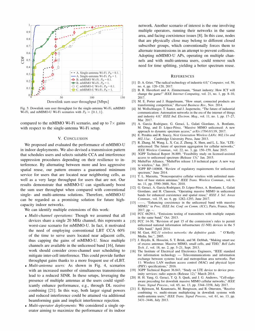
Fig. 5 shows the CDF of the DL sum user throughput, wherethe modulation and coding scheme is selected according to
AP position
0.35
0.4
0.45
0.5
0.65
0.7
0.75
AP
chan
nel
acc
ess
succ
ess
rate
A. Single-antenna Wi-Fi. Ptr = 0.1.
A. Single-antenna Wi-Fi. Ptr = 1.
B. mMIMO Wi-Fi. Ptr = 0.1.
B. mMIMO Wi-Fi. Ptr = 1.
C. mMIMO-U Wi-Fi. Ptr = 0.1.
C. mMIMO-U Wi-Fi. Ptr = 1.
Left AP Central AP Right AP
0.55
0.6
Fig. 3: Channel access success rate for the single-antenna Wi-Fi, mMIMOWi-Fi, and mMIMO-U Wi-Fi scenarios with Ptr = {0.1, 1}.
-10 10 20 30 40 50 60
Downlink SINR per user [dB]
0
0.1
0.2
0.3
0.4
0.5
0.6
0.7
0.8
0.9
1
CD
F
A. Single-antenna Wi-Fi. Ptr = 0.1.
A. Single-antenna Wi-Fi. Ptr = 1.
B. mMIMO Wi-Fi. Ptr = 0.1.
B. mMIMO Wi-Fi. Ptr = 1.
C. mMIMO-U Wi-Fi. Ptr = 0.1.
C. mMIMO-U Wi-Fi. Ptr = 1.
0
Fig. 4: Downlink user SINR for the single-antenna Wi-Fi, mMIMO Wi-Fi,and mMIMO-U Wi-Fi scenarios with Ptr = {0.1, 1}.
[18]. In this figure, we account for the fraction of time spent inUL/DL and for the service time per user. Note that the latter isaffected by the channel access success rate and by the numberof users performing time sharing. As a direct consequence,a user experiences significantly higher throughput under lighttraffic, i.e., for Ptr = 0.1. While all three scenarios achievegood throughput under light traffic, scenario C with mMIMO-U provides noticeable gains in the top 30-th percentile.
The benefits of adopting mMIMO-U at the central AP areeven more significant under heavy traffic, when a more fre-quent channel access facilitates serving each user more often.Moreover, the scheduling mechanism proposed in Section III-C-3, which alternates LBT and eLBT CCA phases, ensuresboth (i) a guaranteed minimum throughput for users locatednear interfering nodes, and (ii) a very large sum throughput forusers that are more immune to interference. Note that whilethe former are served after LBT and contribute to the lowerpart of the CDF, the latter are scheduled after eLBT and arecaptured in the upper part of the CDF. Overall, mMIMO-U demonstrates 4× gains in the median throughput when
Fig. 5: Downlink sum user throughput for the single-antenna Wi-Fi, mMIMOWi-Fi, and mMIMO-U Wi-Fi scenarios with Ptr = {0.1, 1}.
compared to the mMIMO Wi-Fi scenario, and up to 7× gainswith respect to the single-antenna Wi-Fi setup.
V. CONCLUSION
We proposed and evaluated the performance of mMIMO-Uin indoor deployments. We also devised a transmission patternthat schedules users and selects suitable CCA and interferencesuppression procedures depending on their resilience to in-terference. By alternating between more and less aggressivespatial reuse, our pattern ensures a guaranteed minimumservice for users that are located near neighboring cells, aswell as a very large throughput for users that are not. Ourresults demonstrate that mMIMO-U can significantly boostthe sum user throughput when compared with conventionalsingle- and multi-antenna solutions. Therefore, mMIMO-Ucan be regarded as a promising solution for future high-capacity indoor networks.
We can identify multiple extensions of this work:• Multi-channel operations: Though we assumed that all
devices share a single 20 MHz channel, this represents aworst-case scenario for mMIMO-U. In fact, it motivatedthe need of employing conventional LBT CCA 60%of the time to serve users located near adjacent cells,thus capping the gains of mMIMO-U. Since multiplechannels are available in the unlicensed band [16], futurework should consider cross-channel user scheduling tomitigate inter-cell interference. This could provide furtherthroughput gains thanks to a more frequent use of eLBT.
• Multi-antenna users: As shown in Fig. 4, scenarioswith an increased number of simultaneous transmissionslead to a reduced SINR. In these setups, leveraging thepresence of multiple antennas at the users could signif-icantly enhance performance, e.g., through DL receivecombining [21]. In this way, both larger signal powersand reduced interference could be attained via additionalbeamforming gain and implicit interference rejection.
• Multi-operator deployments: We considered a single op-erator aiming to maximize the performance of its indoor
network. Another scenario of interest is the one involvingmultiple operators, running their networks in the samearea, and facing coexistence issues [8]. In this case, nodesthat are physically close may belong to different closedsubscriber groups, which conventionally forces them toalternate transmissions in an attempt to prevent collisions.Adopting mMIMO-U APs, operating on multiple chan-nels and with multi-antenna users, could remove suchneed for time splitting, yielding a better spectrum reuse.
REFERENCES
[1] D. A. Grier, “The radical technology of industrie 4.0,” Computer, vol. 50,no. 4, pp. 120–120, 2017.
[2] B. R. Haverkort and A. Zimmermann, “Smart industry: How ICT willchange the game!” IEEE Internet Computing, vol. 21, no. 1, pp. 8–10,2017.
[3] M. E. Porter and J. Heppelmann, “How smart, connected products aretransforming competition,” Harvard Business Rev., Nov. 2014.
[4] M. Wollschlaeger, T. Sauter, and J. Jasperneite, “The future of industrialcommunication: Automation networks in the era of the internet of thingsand industry 4.0,” IEEE Ind. Electron. Mag., vol. 11, no. 1, pp. 17–27,Mar. 2017.
[5] A. Garcia Rodriguez, G. Geraci, L. Galati Giordano, A. Bonfante,M. Ding, and D. Lopez-Perez, “Massive MIMO unlicensed: A newapproach to dynamic spectrum access,” arXiv:1704.01139, 2017.
[6] E. Perahia and R. Stacey, Next Generation Wireless LANs: 802.11n and802.11ac. Cambridge University Press, June 2013.
[7] R. Zhang, M. Wang, L. X. Cai, Z. Zheng, X. Shen, and L. L. Xie, “LTE-unlicensed: The future of spectrum aggregation for cellular networks,”IEEE Wireless Commun., vol. 22, no. 3, pp. 150–159, June 2015.
[8] 3GPP Technical Report 36.889, “Feasibility study on licensed-assistedaccess to unlicensed spectrum (Release 13),” Jan. 2015.
[9] MulteFire Alliance, “MulteFire release 1.0 technical paper: A new wayto wireless,” Jan. 2017.
[10] 3GPP RP-140808, “Review of regulatory requirements for unlicensedspectrum,” June 2014.
[11] T. L. Marzetta, “Noncooperative cellular wireless with unlimited num-bers of base station antennas,” IEEE Trans. Wireless Commun., vol. 9,no. 11, pp. 3590–3600, Nov. 2010.
[12] G. Geraci, A. Garcia Rodriguez, D. Lopez-Perez, A. Bonfante, L. GalatiGiordano, and H. Claussen, “Operating massive MIMO in unlicensedbands for enhanced coexistence and spatial reuse,” IEEE J. Sel. AreasCommun., vol. 35, no. 6, pp. 1282–1293, June 2017.
[13] ——, “Enhancing coexistence in the unlicensed band with massiveMIMO,” in Proc. IEEE Int. Conf. on Comm. (ICC), Paris, France, May2017, pp. –.
[14] FCC 662911, “Emissions testing of transmitters with multiple outputsin the same band,” Oct. 2013.
[15] FCC 14-30, “Revision of part 15 of the commission’s rules to permitunlicensed national information infrastructure (U-NII) devices in the 5GHz band,” April 2014.
[16] M. Gast, 802.11 wireless networks: the definitive guide. ” O’ReillyMedia, Inc.”, 2005.
[17] J. Hoydis, K. Hosseini, S. T. Brink, and M. Debbah, “Making smart useof excess antennas: Massive MIMO, small cells, and TDD,” Bell LabsTech. J., vol. 18, no. 2, pp. 5–21, Sept. 2013.
[18] The Institute of Electrical and Electronics Engineers, “IEEE standardfor information technology — Telecommunications and informationexchange between systems local and metropolitan area networks. Part11: Wireless LAN medium access control (MAC) and physical layer(PHY) specifications,” 2016.
[19] 3GPP Technical Report 36.843, “Study on LTE device to device prox-imity services; radio aspects (Release 12),” March 2014.
[20] H. H. Yang, G. Geraci, T. Q. S. Quek, and J. G. Andrews, “Cell-edge-aware precoding for downlink massive MIMO cellular networks,” IEEETrans. Signal Process., vol. 65, no. 13, pp. 3344–3358, July 2017.
[21] E. Bjornson, M. Kountouris, M. Bengtsson, and B. Ottersten, “Receivecombining vs. multi-stream multiplexing in downlink systems withmulti-antenna users,” IEEE Trans. Signal Process., vol. 61, no. 13, pp.3431–3446, July 2013.