167
Celano (AQ), Abruzzo ITALY June 16-21, 2002 ABSTRACTS VOLUME Edited by S.G. Evans & S. Martino MASSIVE ROCK SLOPE FAILURE: NEW MODELS FOR HAZARD ASSESSMENT NATO ADVANCED RESEARCH WORKSHOP

Celano (AQ), AbruzzoITALY
June 16-21, 2002
ABSTRACTS VOLUME
Edited by S.G. Evans & S. Martino
MASSIVE ROCK SLOPEFAILURE:
NEW MODELS FOR HAZARDASSESSMENT
NATO ADVANCED RESEARCH WORKSHOP

I
INDEX
ROCKSLIDES AND ROCK AVALANCHES OF THE CENTRAL AND NORTHERN TIENSHANK. Abdrakhmatov, A. Strom…………………………………………………………………..……1
EXPERIMENTAL INVESTIGATION OF LONG DISTANCE ROCK AVALANCHESV.V. Adushkin………………………………………………………………………………………7
ACTIVE TECTONICS, SEISMICITY AND MASSIVE ROCK SLOPE FAILURE IN THEREPUBLIC OF ARMENIAB. S. Yu., A. S. Avanesyan, V. K.Boynagryan ……………………………………………..……..11
ROCK-SLOPE FAILURES IN NORWEGIAN FJORD AREAS: EXAMPLES, SPATIALDISTRIBUTION AND TEMPORAL PATTERNL. Harald Blikra ……………………………………………………………………………………12
GRAVITATIONAL ORIGIN OF ANTISLOPE SCARPS IN BRITISH COLUMBIAJ. J. Clague, S. G. Evans………………………………………………………..……………….… 16
DISINTEGRATING ROCK SLOPE MOVEMENTS IN THE BEAVER RIVER VALLEY,GLACIER NATIONAL PARK, BRITISH COLUMBIA, CANADAR. Couture, S. G. Evans………………………………………………………..……………..…… 19.ROCK SLOPE INSTABILITY; THE TRANSITION TO CATASTROPHIC FAILUREG. B. Crosta………………………………………………………..……………………..……….. 24
FROM CAUSE TO EFFECT – USING NUMERICAL MODELLING TO UNDERSTAND ROCKSLOPE INSTABILITY MECHANISMSErik Eberhardt ……………………………………………………..……………………..…….… 27
SINGLE-EVENT LANDSLIDES RESULTING FROM MASSIVE ROCK SLOPE FAILURE:CHARACTERISING THEIR FREQUENCY AND IMPACT ON SOCIETYS. G. Evans………………………………………………………..………………… ………….…32
ESTIMATION OF ENGINEERING GEOLOGICAL CONDITIONS OF A ROCKSLIDE DAMOF THE LOWER LAKE ON THE KOLSAI RIVERE. Gaspirovich……………………………………………………..……………………..…….… 38
FAILURE MECHANISMS AND RUNOUT BEHAVIOUR OF THREE ROCKSLIDE-DEBRISAVALANCHES IN NORTH-EASTERN ITALIAN ALPS.R. Genevois, P.R. Tecca ………………………………………………..………………..….…… 39
EDOARDO SEMENZA (1927-2002): IMPORTANCE OF GEOLOGICAL ANDGEOMORPHOLOGICAL FACTORS FOR THE IDENTIFICATION OF THE ANCIENTVAIONT LANDSLIDEM. Ghirotti………………………………………………………..……………………..……...… 45
A FRACTURE-BASED CRITERIA TO ASSESS ROCK-MASS SUSCEPTIBILITY TOFAILUREE. L. Harp………………………………………………………..……………………..………… 47

II
ROCK AVALANCHING IN THE NW ARGENTINE ANDES AS A RESULT OF COMPLEXINTERACTIONS OF LITHOLOGIC, STRUCTURAL AND TOPOGRAPHIC BOUNDARYCONDITIONS, CLIMATE CHANGE AND ACTIVE TECTONICSR. L. Hermanns, R. A. Alonso, L. Fauque, S. Ivy-Ochs, P. W. Kubik, S. Niedermann, M. R.Strecker, A. Villanueva Garcia……………………………………..……………………..……..… 52
DIAGNOSTICS FOR FIELD IDENTIFICATION OF ROCK AVALANCHES INVOLVINGCOMPLEX RUN OUT AND EMPLACEMENT, WITH EXAMPLES FROM THEKARAKORAM HIMALAYAK. Hewitt………………………………………………………..……………………..…………… 57
THE ROLE OF LANDSLIDES IN THE TOPOGRAPHIC EVOLUTION OF ACTIVEMOUNTAIN BELTSN. Hovius ………………………………………………………..…………………………………..….…… 62
ROCK AVALANCHE MOTION: PROCESS AND MODELLINGO. Hungr ………………………………………………………..……………………..………...… 66
CATASTROPHIC VOLCANIC LANDSLIDES; THE LA OROTAVA EVENTS ON TENERIFE,CANARY ISLANDS.M. Hürlimann, A. Ledesma………………………………………………………………..……… 70
TECTONIC FEATURES OF THE VAKHSH COMPRESSION THRUST ZONE (TAJIKISTAN) ;MAJOR FACTORS IN GIANT SLOPE FAILURES
A. Ischuk………………………………………………………..…………………..……..……… 75
MODELING THE DYNAMICS OF ROCK AND DEBRIS AVALANCHESR. M. Iverson………………………………………………………..………………………..…… 77
WHY DO LANDSLIDES GO SO FAR ? F. Legros………………………………………………………..……………………..……..…… 82
DEVELOPMENT AND STRUCTURE OF “USOI” LANDSLIDE-COLLAPSE DAMMING,MURGAB RIVER VALLEY, PAMIRSY.A. Mamaev………………………………………………………..……………………..……… 87
RAPID ROCK-MASS FLOW WITH DYNAMIC FRAGMENTATION: - INFERENCES FROMTHE MORPHOLOGY, AND INTERNAL STRUCTURE OF ROCKSLIDES AND ROCKAVALANCHESM. McSaveney , T. Davies ………………………………………………………..…………….… 89
LARGE FLANK FAILURES AT THE VOLCANOES OF THE KURILE-KAMCHATKA ARCI.V.Melekestsev………………………………………………………..…………………………….…….… 93
MODERN LANDSLIDES OF KYRGYZSTAN; RETROSPECTIVE ANALYSIS OF THEIRDEVELOPMENT AT REPRESENTATIVE SITES".A.V. Meleshko, Sh.E. Usupaev, I.A. Torgoev ………………………………..…..…………….… 97
WHICH MODELS ARE AVAILABLE TO UNDERSTAND A LARGE LANDSLIDE SUCH ASLA CLAPIÈRE (SOUTHERN ALPS, FRANCE)?V. Merrien-Soukatchoff ………………………………………………………..…….…..…..…… 98

III
EARTHQUAKE-TRIGGERED LANDSLIDES IN MOUNTAIN AREASW. Murphy ………………………………………………………..……………………..…….… 103
SPECIFIC FEATURES OF LANDSLIDE FACTORS IN THE WEST CARPATHIANSR. Ondrasik………………………………………………………..……………………..…..…… 106
PATTERNS OF ACCELERATION FOR LARGE SLOPE FAILURESD. N. Petley………………………………………………………..……………………..…..…… 110
THE FLIMS ROCKSLIDE; NEW ASPECTS OF ITS MECHANISM AND IMPACTA. V. Poschinger…………………………………………………..……………………..….….… 114
ASSESSING MASSIVE FLANK COLLAPSE AT VOLCANO EDIFICES USING3-D SLOPE STABILITY ANALYSISMark E. Reid and Dianne L. Brien…………………………………………………..….…..……. 117
PREHISTORIC ROCK AVALANCHES, MOUNTAIN SLOPE DEFORMATIONS ANDHAZARD CONDITIONS IN THE MAIELLA MASSIF (CENTRAL ITALY)G. Scarascia Mugnozza, G. Bianchi Fasani, C. Esposito, S. G. Evans ……………….……….….… 121
IMPACTS OF LANDSLIDE DAMS ON MOUNTAIN TOPOGRAPHYR. L. Schuster ……………………………………………………..……………………………... 128
DYNAMICS AND MECHANISM OF DEVELOPMENT OF HUGE SEISMOGENICROCKSLIDES AND ASSESSMENT OF THEIR HAZARD WITH REFERENCE TO THEEXAMPLE OF USOISKY ROCKFAILURE, TAJIKISTAN.A.I.Sheko………………………………………………………..………………………..……… 132
NUMERICAL MODELLING OF ROCK SLOPES USING A TOTAL SLOPE FAILUREAPPROACHD. Stead, J. Coggan………………………………………………..……………………..……… 135
MORPHOLOGY AND INTERNAL STRUCTURE OF ROCK SLIDES AND ROCKAVALANCHES: GROUNDS AND CONSTRAINTS FOR THEIR MODELLING
A. Strom………………………………………………………..……………….………..……… 140
ON GEOMECHANICAL MONITORING OF NATURAL AND MAN-MADE SLOPES.N.M. Syrnikov, Y.S. Rybnov, V.F. Evmenov ……………………………………………..…… 146
TECTONICALLY DETERMINED LARGE COLLAPSES IN THE INNERAND NORTH EASTERN ASIAG.F.Ufimtsev………………………………………………………..……………..…….…..……149
GRAVITATIONAL CREEP AS A POTENTIAL FAILURE MODE OF ROCK SLOPESA.A. Varga ………………………………………………………..……………………..……… 151

THE “PLAYING CARDS” MODEL AS A TOOL TO BETTER UNDERSTANDING LONGRUN-OUT: THE CASE OF THE FLIMS HOLOCENE STURZSTROMP.Wassmer, J.L. Schneider & N.Poller………………………………………………..…….152
BAYPAZA LANDSLIDE, TAJIKISTAN; STRUCTURE AND DEVELOPMENTA.Ischuk & O.V. Zerkal …………………………………………………………….………156
REGIONAL PECULIARITIES OF SEISMICALLY TRIGGERED LANDSLIDES IN THEMOUNTAIN REGIONS OF TAJIKISTANS. Vinnichenko………..……………………………………………………………………..161

1
ROCKSLIDES AND ROCK AVALANCHES OF THE CENTRAL ANDNORTHERN TIEN SHAN
Kanatbek AbdrakhmatovInstitute of seismology, Bishkek, Kyrgyzstan, [email protected] StromHydroproject Institute, Geodynamic Research Center, Moscow, Russia, [email protected]
INTRODUCTION
Tien Shan has many large (106-108 m3) and giant (≥109 m3) rock slides and rockavalanches. In the arid climate, many of them are well preserved and their morphology andstructure can be studied in detail. However, most of them are unknown to the internationalcommunity of landslide researchers. An objective of this paper is to rectify this bypresenting an overview of Tien Shan’s rockslides and rock avalanches. We concentrate onthe central and northern Tien Shan, bounded by the Talasso-Fergana dextral strike-slip faulton the west and by the China-Kyrgyz border on the east. Most of our studies have been inthis part of Tien Shan [1-3, 5, 6, 9-12].
GEOLOGICAL BACKGROUND
The eastern part of the Tien Shan mountain system is a basin-and-range province withsub-parallel neotectonic anticline ridges, divided by wide intermontane depressions withflat, gently inclined bottoms and narrow depressions occupied by deep river valleys. Mostof neotectonic folds are flanked by active faults. Caledonian and Hercynian tectonism hasleft highly complex basement structure. This has had a significant effect on the types ofmassive rock failures there. Despite the altitude of the region, many ridges and valleys werenot affected by glaciation, especially in the central part. Many of the rock avalanchedeposits previously were identified as moraines: only during the last decade have they beencorrectly interpreted. Tien Shan is one of the most seismically active parts of Asia. Strongearthquakes with magnitudes up to 8.2-8.3, associated with surface ruptures and extensiveslope failure took place in the 19th and 20th centuries and paleoseimological data indicatenumerous earlier seismic catastrophes.
CASE STUDIES
We now briefly describe several examples of the massive rock failures in the region.Superb rock slides are found in the deep valleys dissecting the northern slopes of theKyrgyz range. A giant prehistoric rockslide of about 109 m3 lies in the Aksu valley, 60 kmsouth-west from Bishkek city. Its scar, 1.5 km high and 2 km wide, exposes Palaeozoicgranites and terrigenous deposits. The rockslide formed a dam about 500 m high with well-pronounced transverse levees on its surface, now completely cut through by erosion. Thecut exposes detail of the dam's internal structure. Two rock avalanches of 15×106 m3 and 10×106 m3 are located in the Sukuluk valley, about 35 km south-east from Bishkek. These"twin" rock avalanches probably fell in the 1885 Belovodsk earthquake, although this is notmentioned in the earthquake description. Failure occurred on slopes underlain by sandstone,conglomeratic sandstone and andesitic dykes. The rockslides converted into rock

2
avalanches 2-2.5 km long with pressure ridges perpendicular to the sliding axis and highlateral levees bordering the channel-like depressions along the main axes. A huge blockremains inside one of the scars. The rock-avalanche surfaces are composed mainly ofpebble-size debris with only limited amounts of fine material and large blocks.
There are several large rockslides in the Chon-Kemin valley [2, 3]. This was theepicentral area of the 1911 Kemin earthquake (M 8.2±0.3) that caused severe damage andwidespread slope failure. In 1887 and 1889 two earlier seismic catastrophes caused large-scale landslides in the northern Tien Shan – the Vernyi (M 7.3) and the Chilik (M 8.3±0.5)earthquakes, but they affected mainly the eastern – Kazakh part of the region. The onlylarge slope failure in Chon-Kemin valley during the 1911 Kemin earthquake was the Chon-Kaindy rockslide. It mobilised 8-10×106 m3 of fractured marble. Numerous seismicallyinduced landslides in loose Quaternary deposits occurred in its vicinity. Fifteen kmupstream, a large prehistoric rockslide dam, 150-200 million m3 in volume and up to 200 mhigh, blocked the Chon-Kemin valley and its right tributary where small Djashilkul Lakestill exists. The dam was breached and its internal structure can be seen in the gorge. Thisrockslide fell from the right bank of the Chon-Kemin valley where the bedrock isgreenschist. The surface of the former dam is covered by large angular boulders while itsinternal part is intensively crushed rock debris. Nearby, two rockslides of similar volumeblock right and left tributaries valleys of the Chon-Kemin. Several large rockslides areconcentrated 10 km upstream – on the northern slopes of Chon-Kemin valley at Djaia. Oneof them dammed the Chon-Kemin valley immediately upstream from the mouth of theBashy-Djaya river. Its frontal part is about 100 m above the river, and overlies the terminalQIII moraine. A 14C AMS date of a paleosol developed on the moraine and buried by theBashi-Djaya rockslide debris gave an age of 7000-7950 BP [3]. The structure of the distalpart of rockslide and its contact with the underlying soil can be seen in a road cut.
The 1911 Kemin earthquake also caused slope failures in the valleys that open intothe Issyk-Kul lake along east-west trending lineament that ruptured during the Keminearthquake. Two rockslides were seen in a reconnaissance soon after the event, and severalother mass movements may also be related to it. A rockslide, 7 km north of Ananevovillage, is one of the more prominent features produced by this earthquake. Light-colouredgranites outcrop in its triangular 250m-high scar that is more than 600 m wide at its base.Failure took place just above a thrust, gently dipping towards the north-east that ruptured inthe 1911 earthquake. The landslide deposit is more than 100 m thick and covers an area 800m long and up to 600 m wide. It is about 40×106 m3 in volume. An interesting feature of theAnanievo landslide is its steep, high front, indicating an abrupt halt without impact againstan obstacle. The rockslide deposit is of crushed granite, with huge blocks below the scarand in the central part. In front of the granite debris there is a shelf 7 to 10 m highcomposed of a loamy material from loose deposits resting at the slope foot scraped up bythe moving debris, as if by a bulldozer. We believe that this «bulldozing» reduced therunout of the landslide. Large fragments of buried soil and loamy sand subsoil overlain bycrushed granite at the rockslide front indicate thrusting above the basal sliding surface. Theoverall geometry of the front can be described as a duplex-like structure [5]. In the upperreaches of the Chon-Aksu valley, there are other remarkable features most probaballyrelated to the same earthquake. The bottoms of two valleys of its left tributaries (Lower andUpper Kulagan-Tash) are filled with debris and blocks of granite and gneiss with leveesindicating "flow" of this material. The one in Lower Kulagan-Tash is 4 km long, and movedfrom 3800-4000 m a.s.l. to 3000 m a.s.l. That is Upper Kulagan Tash is 2-2.5 km long, andmoved from 3800 m a.s.l. to 3200 m a.s.l. There are scars above these "stone rivers". We donot know if they are rock glaciers or rock avalanches, as features typical of both are

3
recognised.There are interesting rockslides on the southern slopes of the Kyrgyz Range where
it joins the Suusamyr intermontane depression, and further south in the valleys ofKokomeren river and its tributaries. In the eastern part of the Suusamyr depression,rockslides and rock avalanches are associatied with recent ruptures. They are concentratedin several limited areas ~15 km long, separated by gaps of similar size without significantslope failures. It suggests a seismic origin for both the ruptures and the rockslides. The mostinteresting is the Snake-head rock avalanche. A massive failure of Palaeozoic sandstone inthe upper reaches of an unnamed creek forms a huge accumulation of debris at the foot ofthe collapsed slope. Down valley lies a narrow "stream" of crushed debris about 2.5 kmlong with a pronounced distal lobe with transverse levees bounded by a narrow laterallevee. Material in the distal part of the rock avalanche deposit is crushed to clasts a fewcentimetres across, but with bigger boulders on its surface.
In the upper part of Kokomeren river basin there are several long-runout rockavalanches of different morphological types [10]. These are the Seit and Aincient primaryand the Chongsu and Sarysu secondary rock avalanches up to 4.5 km long, and thePleistocene Kokomeren rockslide about 1.0 km3 in volume. The latter fell from the leftbank of the Kokomeren river and formed a dam up to 400 m high. Its 1.6km-high scarexposes dark-grey sandstone, reddish granite and alternating granite and sandstone sheets.The rockslide rests on a terrace 150 m above the riverbed and is completely cut by the river.Its frontal part filled the ancient valley 40 m above the present-day riverbed on its rightbank. This rockslide is of particular interest because its internal structure can be seen indetail [9, 11]. Its upper part, up to 250 m thick, is composed of blocks and huge boulders ofgranite, overlain, in turn, by a layer of blocks and big fragments of sandstone. The lowerpart, up to 150 m thick, consists of strongly shattered rocks with a grain-size composition offine sand, divided into granite and sandstone layers. The same succession occurs in theisolated frontal part on the other side of the river. The boundary between the blocky andshattered parts is abrupt, without a transitional zone. The succession of layers correspondsto the lithostratigraphy in the slide scar, so that the structure of the bedrock outcrops isretained in the rockslide deposit. It shows that lower part of the sliding mass, up to 150 mthick, moved as a single unit and that its comminution is the result of mechanical crushingrather than subsequent weathering. Another Pleistocene rock avalanche with stratificationof debris lies on the right bank of Kokomeren river approximately 3 km downstream ofKokomeren slide. About 20-40×106 m3 fell from a slope composed of granites of differenttypes. The lower 20-30 m of debris are composed of intensively crushed, grey granite debriswhile the upper 30-50 m are of angular boulders, up to 1-2 m across, of red gneissoidgranite. The boundary between these layers is abrupt and may be traced for at least 800 m.Downstream, where the Kokomeren River crosses the western part of the Djumgalintermontane depression, is the Northern Kara-Kungey rock avalanche, the distinctiveSouthern Kara-Kungey secondary rock avalanche [10] and, between them, a huge landslidein Neogene and Quaternary deposits. There are several other large rock avalanches near thisdepression at the Mingteke tract and in the Kokomeren valley downstream of the Aralvillage.
Dozens of rock slides and rock avalanches, recent ruptures, sackung and uniquecaldera-like collapses of watersheds concentrate along the Naryn – Lower Kokomeren –Minkush river valleys for more than 120 km [8, 12]. In the western part of the zone, at themouth of the Djuzumdy-Bulak Creek, 6 km upstream from the Kambarata-2 dam site large-scale failures have occurred twice from the same scar. Older avalanche deposits rest onterraces 60-100 m high, while a younger rockslide forms a compact dam with stratified
4
internal structure in the present day gorge. Rockslides in the lower part of the KokomerenRiver valley and its tributaries exemplify a variety of different types of massive slopefailures – translational and rotational rockslides, some of which converted into rockavalanches.
Other unique features are located at the Western Akshiyriak Range in the centralpart of the Naryn River basin near Kazarman. These include the giant prehistoric Beshkiollandslide and three Chaartsh rock avalanches [1, 2, 6, 11]. The Beshkiol landslide is about10 km3 in volume on the northern slope of the Akshiyriak Ridge 15-22 km downstream ofthe Alabuga River mouth. It formed a natural dam about 200 m high that blocked the NarynRiver over a length of 6 km. The 70km-long lake had been filled by lacustrine deposits formore than 70% of its maximum depth until the river cut a new gorge through the right-bankbedrock. The landslide is composed mainly of conglomerate and sandstone of Neogene agewith salt and gypsum interbeds. Neogene deposits form a syncline in the eastern part of theTogus-Torau depression, separated from the Akshiyriak Range by a reverse fault. Thesliding surface appears to coincide with the bedding surface near the base of the Neogene ata depth of 200-300 m. The upper part of the scar, that can be clearly defined on the slope upto 3400 m and from which a rockfall about 300×106 m3 in volume fell, is composed ofPalaeozoic rocks.
At the foot of the Chaartash Mountain there is a group of three long run-out rockavalanches, about 100-300 x106 m3 in volume each. They fell from slopes composeddominantly of Palaeozoic granites, and travelled from 4 to 7 km along the flat bottom of theTogus-Torau intermontane depression. The western and central avalanches (Chaartash-1and 2) fell from the steep slopes of short dry gullies and the eastern one (Chaartash-3), fromthe slope facing the depression itself. Chaartash-3 formed a debris apron 3.5 km long, 1.5km wide and about 50 m thick with a longitudinally grooved surface. There are two minorrock avalanches on the main avalanche surface: these may be secondary avalanches, ejectedfrom the compact tail part. They travelled 2.0 – 2.5 km, and the equivalent coefficients offriction (H/L) are 0.18 and 0.16, much lower than values typical of other rock avalanches ofsuch a limited volume (about 1×10⁶ m3).
In the eastern part of the Tien Shan in the Inylchek river valley, 15 km downstreamfrom the terminus of the glacier there is a cluster of rock avalanches that fell from bothsides of the valley. The younger one is the Inylchek rockslide of about 50×106 m3 that fellfrom the right bank to overlie the frontal part of the earlier left-bank Atdjailau transitionalslide. This older slide formed a pancake-shaped avalanche about 2 km across, composed oflimestone debris. The Inylchek rockslide is a classical example of a stratified rockavalanche [9]. Its 70m-thick deposits consist of layers of fragments of the rocks that outcropin its scar, preserving the same succession – black limestone, black schist and red granite.
Several large rockslides are located along the active Talas-Fergana fault – one of thelargest transverse fault zones of Central Asia. The biggest and most distinctive one is theKarasu rockslide of about 250 x 106 m3 that dammed the Karasu River forming a beautifullake [7]. The 350m-high rockslide dam is accompanied by a distinctive tongue of secondaryavalanche that slid from its downstream slope for about 700 m. Though we focus on thearea east of the Talas-Fergana fault, we should mention several interesting rockslides ofeasy access that are located further west. One is the Sarychelek rockslide in the upperreaches of Western Karasu River. It is a giant blockage with a very complicatedmorphology and structure of as yet unknown origin [4]. Another large rockslide formed a300m-high dam at the mouth of the Eastern Karasu River. It blocked both this and NarynRiver valleys 3 km downstream of the present-day site of the Toktogul dam. While thepowerful Naryn River cut through the blockage to expose an excellent section through the

5
rockslide deposit, the smaller Karasu River filled its lake with alluvial and lacustrinedeposits on which Karakul now is built. A third unique rockslide about 17 km2 in area and~2 km3 in volume lies 12 km south of Karakul in the Karakol River valley.
These are only some of the large Tien Shan slope failures: many still await research.
TYPES OF FAILURE
Due to the intensive deformation of the Palaeozoic and Precambrian basement of theTien Shan, large-scale translational «bedding-plane" rock slides (similar to Flims, Seimarehor Avalanche Lake) are rare in the studied region. One of the most distinctive examples isthe At-Djailau rock avalanche on the right bank of the Inylchek valley. Most of therockslides briefly described here occurred from slopes composed of granite, or intensivelyfolded metamorphic rocks or from slopes of complex structure. The latter slides providerare opportunities to reconstruct the style of rockslide motion by comparison of the initial(in the scar) and final (in rockslide deposits) positions of different lithologic units. Suchstudies could be performed both at high natural dams such as the Kokomeren, Aksu andDjashilkiol landslides as well as at some of the longer runout rock avalanches.
SPATIAL DISTRIBUTION
The Tien Shan rock slides and avalanches usually concentrate in elongated zonesrelated to active faults (Kemino-Chilik, Aksu-Chon-Aksu, Naryn-Kokomeren, WesternAkshiyriak, etc.). Along these faults, there very often are clusters of several large slopefailures within a limited areas separated by gaps without significant rockslides. It is bestillustrated in the Chon-Kemin and North Suusamyr areas. Concentration of rockslides atsome "knots", as well as their association with recent ruptures, leads us to hypothesise thatthe slope failures are caused by earthquake strong motion. Since data on the absolute agesof these features are limited, we can only prove this hypothesis for those observed afterhistorical earthquakes.
REFERENCES
1. Abdrakhmatov K. E., I.N. Lemzin (1989). Active faults of the Alabuga-Naryn depression. IlimPublishing House, Frunze, 78-90. (in Russian).
2. Chedia O.K., K. E. Abdrakhmatov, I.N. Lemzin, A.M. Korjenkov (1994). Seismogravitationalstructures of Kyrgyzstan. In: Cenozoic geology and seismotectonics of Tien Shan. IlimPublishing House, Bishkek, 85-97. (in Russian).
3. Delvaux D., K. E. Abdrakhmatov, I.N. Lemzin, A.L. Strom (2001). Landslides and surfacebreaks of the 1911, Ms 8.2 Kemin earthquake, Kyrgyzstan. Russian Geology and Geophysics.42, No 10.
4. Fedorenko V.S. (1968). Tectonic and seismic phenomena and their significance in catastrophicrock falls and landslides formation (in the regions of Chatkal and Alay orogens). In: Problemsof engineering geology and soil maechanics, 2 issue, Moscow State University, 229-244. (inRussian).
5. Havenith H-B., A. Strom, K. Abdrakhmatov, D. Jongmans, D. Delvaux, F. Calvetti and P.Tréfois (In press). Seismic triggering of landslides. Part A: Field evidence of involvedgeological factors.

6
6. Lemzin I., K. Abdrakhmatov (1989). Geology and tectonics of the Cenozoic deposits of theToguz-Torau depression. In: The Tien Shan during newest stage of its geological development.Ilim Publishing House, Frunze, 65-77. (in Russian).
7. Matveev Yu. D.(1968). Patterns of development of grandiose rock falls and landslides in theregion of Toktogul dam construction. In: Problems of engineering geology and soil maechanics,2 issue, Moscow State University, 245-258. (in Russian).
8. Orlov L.N. On the kinematics and dynamics of the overthrusts at the boundary of the Northernand Middle Tien Shan. Seismotectonics and seismicity of Tien Shan. Ilim Publishing House,Frunze, 1980, 50-59. (in Russian).
9. Strom, A.L. (1994). Mechanism of stratification and abnormal crushing of rockslide deposits.Proc. 7th International IAEG Congress, V. 3, 1287-1295, Rotterdam, Balkema.
10. Strom, A.L. (1996). Some morphological types of long-runout rockslides: effect of the relief ontheir mechanism and on the rockslide deposits distribution. Landslides. Proc. of the SeventhInternational Symposium on Landslides, 1996, Trondheim, Norway. Edited by K. Senneset.,1977-1982, Rotterdam, Balkema.
11. Strom A.L. (1998). Giant ancient rock slides and rock avalanches in the Tien Shan Mountains,Kyrgyzstan. Landslide News, No 11, 20-23.
12. Strom A.L. (2000). Caldera-like collapses at the watersheds in the central Tien Shan: theirstructure and possible mechanism. Landslides in research, theory and practice, V. 3, Edited byE. Bromhead, N. Dixon and M-L. Ibsen, 1413 - 1418.

7
EXPERIMENTAL INVESTIGATION OF LONG DISTANCE ROCKAVALANCHES
V.V. AdushkinInstitute of geospheres dynamics, Russian Academy of Sciences, Moscow, Russia.
Present the results of observations of large landslides and rockfalls triggered byunderground nuclear explosions into mountain massif at the test site in Novaya Zemlya andalso by strong earthquakes and large-scale volcanic explosions.
In recording external phenomena produced by underground nuclear explosions inmountain areas, we registered rockslides over a wide range of volumes (from tens ofthousands to a hundred million cubic meters). It turned out that for rockfalls with a volumeof �10 6 m3 or greater, the rock mass is more mobile and form long distance rockavalanches. An especially large rockslide was observed in nuclear tests in tunnels on theNovaya Zemlya testing area [1]. The largest rock avalanche with a volume of 8 �107 m3
produced by explosion in the tunnel B-1. The main dimensions of rock avalanches thatformed during the largest rockslides are shown in Table 1.
Table 1.Explosion B-1 A-8 A-6 A-10 A-2 A-9 A-3 A-12
V, m3 8·107 2·107 8·106 5·106 2·106 5·105 105 4·104
S, m2 3,5·106 7,5·105 4·105 2,2·105 1,5·105 6,5·104 3·104 2·104
H, m 400 350 450 350 300 350 430 300L, m 1900 900 1200 900 700 750 900 550L/H 4,75 2,57 2,67 2,57 2,33 2,14 2,1 1,83
Here and below, V and S are the volume and area of the avalanche, respectively, H is theheight of the center of gravity of the rock on the slope, and L is the maximum range of theavalanche front from the projection of the center of gravity of the slope rock onto therockfall on the surface of the avalanche. For almost all explosions, the relief was identicalfor rockslide: the falling rock was able to move freely down the slope and further over anarea with a weak slope (2-50) down to horizontal regions. Under these conditions theavalanche front traveled distances much greater than might be expected for a rockslideaccording to the law of dry friction. Rock avalanche "spread" over the surfacecomparatively uniformly, so that the ratios of the area and width of the avalanche to the areaand width of the fallen region on the slope were 1,2-2,5 and 1,1-1,3 respectively. Forvolume of fallen material in excess of 106 m3, the average thickness of the avalanche was20-27 m. As the rockfall volume increased, the relative range of the avalanche increasedmarkedly: from L/H�2 for volumes of 104-105 m3 to L/H�5 for volumes of the order of108 m3. These facts imply that with increase in the scale of rockfall, the motion of rockchanges and becomes similar to the motion of a viscous fluid.
The processes of rockfalls and avalanches motion were fixed by rapid filming. Thelifting velocity of the slopes surface were measured using light points, and velocimeters.Volumes and areas of the avalanches were calculated using surface mapping and aerialphotographs with an accuracy of about 10%-20%. Filming date have permitteddetermination velocity spreading of the rock slide debris. For largest avalanche with avolume of 8�107 m3 (explosion B-1) the maximum velocity of the front is about 60 m/sand occurs about 25 seconds into slide. Fully time of avalanche spreading was 55 seconds.

8
Also in detail was fixed by filming registration the development of the process of rockfalland avalanche motion in the time of explosion A-10 [2]. The total volume of rockfall wasabout 5�106 m3. The maximum velocity of the front is about 45 m/s and occurs about 12seconds into slide. Fully time of avalanche spreading was 30 seconds.
The rockfall on the slopes of mountain were triggered by seismic shaking after thepowerful underground explosion. Parameters of the seismic waves on the slopes wereregistered by velosimeters. Maximum particle velocity on the slope where take placerockfall change into diapason from 8 m/s up to 25 m/s. On the basis of the measuring weredetermined critical conditions of the rise avalanche in the dependence from the intensive ofthe seismic waves and the slope angles.
To analyze the motion of rockfalls and avalanches of even larger volumes, thatvolumes rockfall on the Novaya Zemlya test site, we used the well-known date on thelargest rockslides occurring in nature as result of earthquakes and during large explosivevolcanic eruptions [3, 4]. Table 2 shows the dimensions of some of such avalanches.
Table 2.Event Country V, m3 L, m H, m L/HElm Switzerland 107 1,7�102 5,5�102 3,1
Madison USA 2,8�107 1,6�102 4�102 4,0Frank Canada 3,7�107 3,2�102 9,2�102 3,5
Goldau Switzerland 3,9�107 1,67�102 5,6�102 3,0Jangly Peru 5,7�107 1,52�104 3,05�103 5,0Aini Tadjikistan 108 3�103 6�102 5,0Khait Tadjikistan 5�108 6�103 8,5�102 7,0Flims Switzerland 1,25�1010 1,62�104 1,22�103 13,3
Seidmarech Iran 2,1�1010 1,45�104 9,2�102 15,9Shiveluch Russia 1,6�109 1,5�104 1,7�102 9
Bezymyannyi Russia 8�108 (1,5-1,8)�104 2�103 7-9Kamen Russia 109 2,3�104 (2,5-2,8)�103 8-9
Sant-Helens USA 2,7�109 2�104 (1,7-2) �103 10-12
One can see from Table 2 that in nature the formation of the order of 1010 m3 and therange of propagation of the avalanches exceeded the height of the fallen region by a factorof 13-16. Some rock avalanches of natural origin had volumes of 107-108 m3, correspondingto the dimensions of the largest avalanches at the Novaya Zemlya test site.
Interesting features of the fall of rock waste dumps were recorded at the Centralmine in Khibini mountains [5]. Stacking of these dumps is carried out on the slopes of theRosvumchorr plateau at elevation of 900-1000 m. The steepness of the slopes is 30-500. Asrock is accumulated, sudden falls of these rock dumps mixed with ice and snow occur. Thevolumes of a number of such rockfalls and the range of propagation of their associatedavalanches are presented in Table 3.
Table 3Rock avalanche
number1 2 4 5 6 8 9 15 17
V, m3 2�106 7�105 1,5�106 1,3�106 2,4 106 2,6 106 6 106 3�105 4 106
9
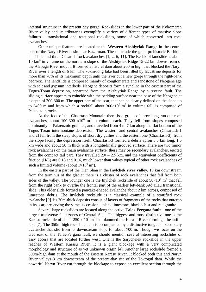
L, m 1100 400 1000 500 1100 900 3000 240 1600H, m 400 250 400 250 400 370 650 170 500L/H 2,7 1,6 2,5 2,0 2,7 2,4 4,6 1,4 3,2Sometimes, rockfalls from mountain slopes occur under conditions of narrow
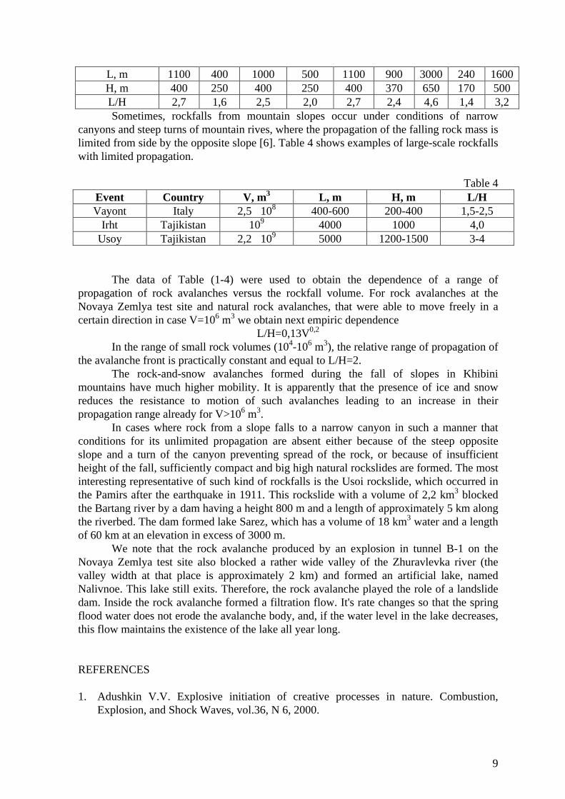
canyons and steep turns of mountain rives, where the propagation of the falling rock mass islimited from side by the opposite slope [6]. Table 4 shows examples of large-scale rockfallswith limited propagation.
Table 4Event Country V, m3 L, m H, m L/HVayont Italy 2,5�108 400-600 200-400 1,5-2,5
Irht Tajikistan 109 4000 1000 4,0Usoy Tajikistan 2,2�109 5000 1200-1500 3-4
The data of Table (1-4) were used to obtain the dependence of a range ofpropagation of rock avalanches versus the rockfall volume. For rock avalanches at theNovaya Zemlya test site and natural rock avalanches, that were able to move freely in acertain direction in case V=106 m3 we obtain next empiric dependence
L/H=0,13V0,2
In the range of small rock volumes (104-106 m3), the relative range of propagation ofthe avalanche front is practically constant and equal to L/H=2.
The rock-and-snow avalanches formed during the fall of slopes in Khibinimountains have much higher mobility. It is apparently that the presence of ice and snowreduces the resistance to motion of such avalanches leading to an increase in theirpropagation range already for V>106 m3.
In cases where rock from a slope falls to a narrow canyon in such a manner thatconditions for its unlimited propagation are absent either because of the steep oppositeslope and a turn of the canyon preventing spread of the rock, or because of insufficientheight of the fall, sufficiently compact and big high natural rockslides are formed. The mostinteresting representative of such kind of rockfalls is the Usoi rockslide, which occurred inthe Pamirs after the earthquake in 1911. This rockslide with a volume of 2,2 km3 blockedthe Bartang river by a dam having a height 800 m and a length of approximately 5 km alongthe riverbed. The dam formed lake Sarez, which has a volume of 18 km3 water and a lengthof 60 km at an elevation in excess of 3000 m.
We note that the rock avalanche produced by an explosion in tunnel B-1 on theNovaya Zemlya test site also blocked a rather wide valley of the Zhuravlevka river (thevalley width at that place is approximately 2 km) and formed an artificial lake, namedNalivnoe. This lake still exits. Therefore, the rock avalanche played the role of a landslidedam. Inside the rock avalanche formed a filtration flow. It's rate changes so that the springflood water does not erode the avalanche body, and, if the water level in the lake decreases,this flow maintains the existence of the lake all year long.
REFERENCES
1. Adushkin V.V. Explosive initiation of creative processes in nature. Combustion,Explosion, and Shock Waves, vol.36, N 6, 2000.

10
2. Adushkin V.V., Spungin V.G. The influence granular structure of rockfalls on theirspeading along mountain slopes. Proceedings of the third international Conference onMechanics of Jointed and Faulted Rock. Vienna, Austria, 6-9 April 1998, pp. 541-546.
3. Bolt B.A., Horn W.L., MacDonald G.A., Scott R.F. Geological hazards, Springer,Heidelberg, 1977.
4. Aprodov V.A. Volcanos [in Russian], Mysl', Moscow, 1982.5. Krasnosel'skii E.V., Kalabin G.V. et al., Rock dumps on mountain slopes [in Russian],
Nauka, Leningrad, 1975.6. Miller L. Landslide in the Vayont valley. Problems of Engineering Geology (collected
scientific papers), Mir, Moscow, 1967.

11
ACTIVE TECTONICS, SEISMICITY AND MASSIVE ROCK SLOPE FAILURE INTHE REPUBLIC OF ARMENIA
Balassanian S. Yu., Avanesyan A. S., Boynagryan V. K.Armenian National Survey for Seismic Protection, Government of the Republic of Armenia
The Republic of Armenia is a typical mountain country with well expressed mountainrelief. The average altitude of the territory of Armenia is 18000 meters above sea level, themaximum altitude is 4095 meters (Mount Aragats) and the minimum 380 meters located onNorth of Armenia (the Debed River Canyon). The recent tectonic and seismicity in theregion evidences currently continuing orogenic processes. Appropriate relation betweenactive tectonics, seismisity and massive rock slope failure is considered.
In the paper landslides and rock falls influencing massive rock slope failure are observed asthe main and more spread geological processes.
The factors forming them are brought as follows:- location relief, that defines slopes angle;- types and physical-mechanical properties of the rocks and ground mapping up the
slopes;- anthropogenic impact;- External physical influences affecting slopes stability.
Analysis of various factors affecting massive rock slope failure shows that the dominatingfactor in seismicity. The examples of massive rock slope failure from the major earthquakesin the territory of Armenia, namely Zangezour (1931, M=6.3), Kajaran (1968, M=5.0) andSpitak (1968, M=7.0) are given.
On the basis of the above mentioned factors the possible methodology for landslidesprediction and development of early warning system for landslide hazard are suggested.

12
ROCK-SLOPE FAILURES IN NORWEGIAN FJORD AREAS: EXAMPLES,SPATIAL DISTRIBUTION AND TEMPORAL PATTERN
Lars Harald Blikra ([email protected])Geological Survey of Norway, N-7491 Trondheim, Norway
INTRODUCTION
Large rock avalanches represent one of the most serious natural hazards in Norway,exemplified by the Tafjord disaster in 1934 when 3 mill m3 dropped into the fjord. Thetsunami generated by the avalanche reached a maximum of 62 m above sea level. Duringthe last 100 years, 174 people have lost their lives in tree such events in a limited region innorthern West Norway. Although high risk is related to such events, very little attention hasbeen paid to hazard assessment. During the last five years, the Geological Survey ofNorway has worked on topics related to the geographic distribution and temporaloccurrence of rock-slope failures in order to define background hazard levels (Blikra &Anda, 1997; Anda & Blikra, 1998; Blikra et al., 1997; Blikra et al., 2002). More specificstudies have also been performed on potential future unstable rock-slope areas. The resultspresented are parts of projects performed in corporation with Norwegian County Councils(Møre & Romsdal, Sogn & Fjordane and Troms), the National fund for natural damageassistance and the Norwegian Geotechnical Institute.
TYPES OF FAILURES
Large-scale rock-slope failures in Norway range from sliding of relatively intact masses ofrock to fully disintegrated and fast-moving rock avalanches (Fig. 1). Some of the unstablerock-slope areas are characterized by major gravitational faulting with deep clefts withdistinct horizontal displacements. One of the largest is localised in the valley Romsdalen,covering a more than 2 km by 200 m large area. The faults are characterised by more than20 m deep crevasses and horizontal displacement of more than 20 m. Several rock-avalanches have been triggered from this area in the past, demonstrated by a series of rock-avalanche deposits in the valley. Gravitational faults and fractures also occur in northernNorway, and some of them are situated directly above deep fjords (Fig. 1C).
Rock-slope failures developed into true rock avalanches is the dominating type ofevents in Norway, mainly due to the fact that the Norwegian fjord and valleys arecharacterized by a high relief. Rock-avalanche deposits have been investigated in detailboth on land and in the fjords. Many of them are characterised by bouldery cones or lobes,often with chaotic morphology with ridges, mounds and intervening basins/ponds. Many ofthem, especially when reaching fine-grained deposits in valleys or fjords, have extensivedebrisflow deposits outside the bouldery rock-avalanche deposits. These are thought to bethe result of remobilisation of deposits during the impact of large rock volumes on thevalley or fjord floor.
A selection of fjords was covered by swath bathymetry and later by a seismic net inorder of mapping rock-avalanche deposits. The data demonstrate that this is an effectivemethod in mapping the distribution of such deposits (Fig. 1A), and the seismic stratigraphyalso gives indications of the temporal pattern. Some of the largest avalanches have a cone-shaped morphology with a bouldery surface while others are smaller and can be seen on thefjord bottom as distinct concentric wavelike features around a core of rock debris. Most ofthe avalanches have caused severe deformations of underlying sediments. Extensive folding

13
and faulting have also been observed in outcrops and on earth-penetrating radar dataconnected with rock avalanches on land. An enormous rock avalanche, estimated to morethan 100 mill m3, is mapped on land in one of the steep fjord areas of northern WestNorway. The avalanche debris could be traced into the fjord with an outrun distance ofmore than 2 km along the fjord bottom. Below the slide scar from the Tafjord failure in1934 at least tree individual rock-avalanche deposits is identified, with the 1934 avalanchebeing the smallest. In addition to the boulder cone there can be seen an outer ‘splash’ zoneinterpreted to be formed by secondary massflows (see 3D-model in Fig. 1A). Similardeposits have also been demonstrated in excavations in distal parts of some rock-avalanchesonshore.
Figure 1. Rock-slope failures in Norway. A. View of Hegguraksla in Tafjord with prominent slidescar. The 3D image from swath batymetry shows the rock-avalanche deposits in the fjord. Boulderydeposits from the Hegguraksla failure and the outer part of the Tafjord event in 1934 is clearlyvisible on the image; B. Rock-slope failure on Oppstadhornet in northern West Norway, showingthe master fault in the back of the collapse field, and a major, wide-open cross-crevasse (fromBlikra et al., 2002); C. A 3D model of one of the gravitational-slide blocks on Nordnesfjellet inNorth Norway, showing a well-defined slide scar and several other fractures or clefts within theblock. The area is about 1 km long.
SPATIAL DISTRIBUTION
Geological mapping on land and in fjords of parts of West and North Norway has identifieda high frequency of such events throughout the last 10 000 years, and the geographicdistribution show a clustering in specific zones. Numerous gravitational faults and rock-slope failures occur in certain regions in Troms, North Norway. The most frequent featuresare large-scale rock avalanches and rock glaciers of rock-avalanche origin. More than 150
14
such features have been mapped in one of the regions, covering an area of c. 7000 km2. Innorthern West Norway, up to 200 individual events are registered, with distinctconcentrations of events in the inner fjord areas. Furthermore, some minor clusters alsooccur in the outer coastal portions. The largest concentration on land is found in Romsdalenin West Norway, were more than 15 large rock avalanches cover almost the entire valleyfloor over a distance of 25 km. In Tafjorden, more than 10 rock-avalanche deposits havebeen mapped in the fjord covering a distance of less than 7 km. A database containinghistorical avalanche events also clearly shows the high number of rock-avalanche events inthe inner fjord areas. Altogether 27 of these recorded events have caused tsunamis. Fromthe data on geologically mapped rock-avalanche events, and registrations of historicalevents, it can be concluded that the high-risk areas are in the inner fjords of northern WestNorway. The possibility that large earthquake(s) have played a role for the clusters of eventscannot be excluded. Actually, the geographic concentration of rock avalanches hints at acommon triggering mechanisms, e.g. one or more earthquakes.
TEMPORAL PATTERN
Some events have been dated by the radiocarbon method or indirectly dated by useof seismic stratigraphy or sea-level curves (Table 1). All dated events in North Norwayshows that they are old, and from shortly after the deglaciation. The clustering of rockglaciers, originated by massive rock-slope failures, indicate that they were formed during orbefore the Younger Dryas period (e.g. 13 000 – 11 500 years BP).
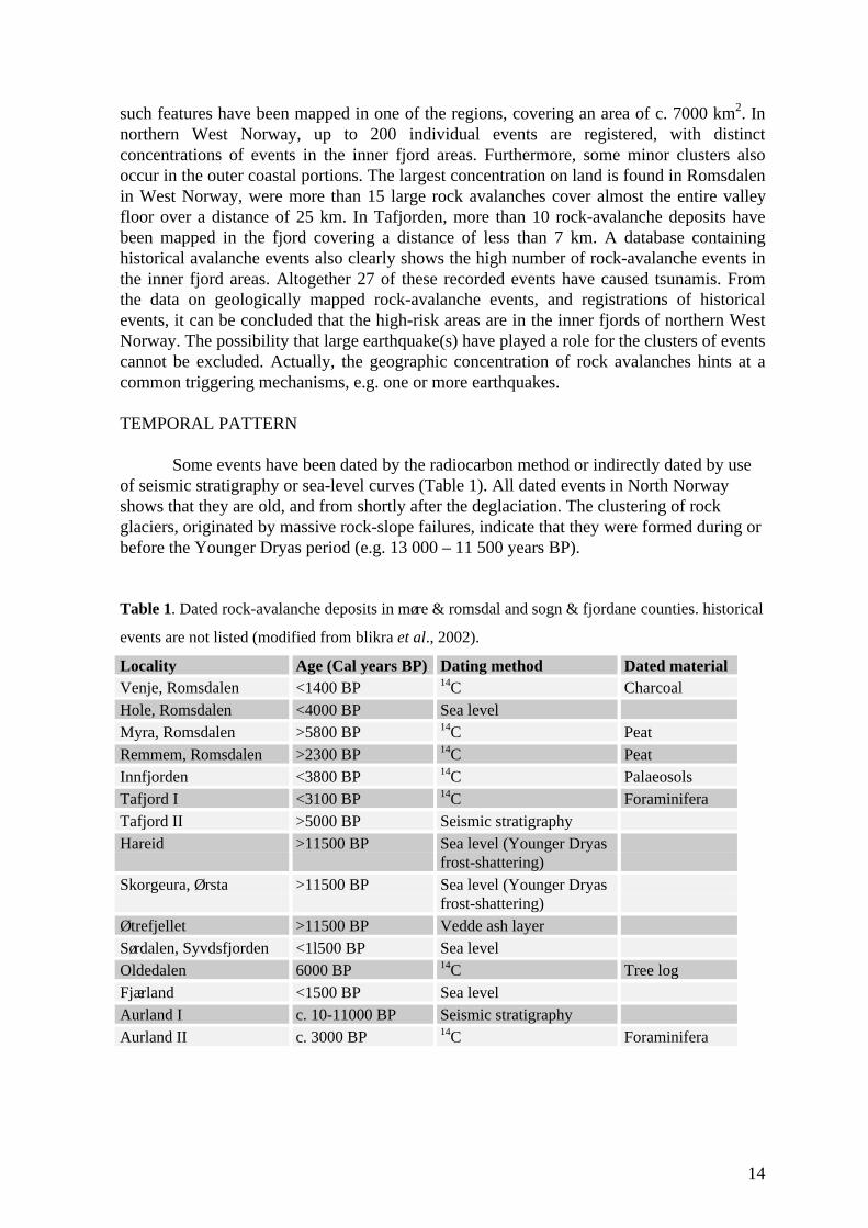
Table 1. Dated rock-avalanche deposits in møre & romsdal and sogn & fjordane counties. historical
events are not listed (modified from blikra et al., 2002).
Locality Age (Cal years BP) Dating method Dated materialVenje, Romsdalen <1400 BP 14C CharcoalHole, Romsdalen <4000 BP Sea levelMyra, Romsdalen >5800 BP 14C PeatRemmem, Romsdalen >2300 BP 14C PeatInnfjorden <3800 BP 14C PalaeosolsTafjord I <3100 BP 14C ForaminiferaTafjord II >5000 BP Seismic stratigraphyHareid >11500 BP Sea level (Younger Dryas
frost-shattering)Skorgeura, Ørsta >11500 BP Sea level (Younger Dryas
frost-shattering)Øtrefjellet >11500 BP Vedde ash layerSørdalen, Syvdsfjorden <1l500 BP Sea levelOldedalen 6000 BP 14C Tree logFjærland <1500 BP Sea levelAurland I c. 10-11000 BP Seismic stratigraphyAurland II c. 3000 BP 14C Foraminifera

15
Other radiocarbon dated events show that they occurred shortly after thedeglaciation, 10 500-11000 years BP. Only one historical event is recorded in historicaltimes in this region.
It has earlier been postulated that most rock avalanches formed shortly after the lastdeglaciation, but the present studies show that this needs major modification. The data fromnorthern West Norway indicate that many of them occurred during the last 5000 years, withseveral dates around 3000 BP. The general stratigraphy based on seismic data in Tafjord,were a series of rock-avalanche events have occurred, demonstrates that individual events isspread throughout the postglacial time, but with a higher frequency in the upper half of theHolocene. The time constraint of the gravitational fractures and rock avalanches in the outercoastal area of northern West Norway is weak, but it is suggested that most of themoccurred shortly after the deglaciation (15-14 000 cal. BP).
CONCLUSIONS
The spatial and temporal pattern of rock-avalanche events in Norway demonstratesthat such events are common in some areas, and that the risk of future events needs to betaken into account. The data indicate a return interval of more than 1 event each 1000 yearsin some of the fjords. The risk level is high due to large consequences related to destructingtsunamis. Detailed investigations of potential unstable rock-slope areas are needed in thefuture, and especially detection of ground movements using new techniques in differentialradar interferometry needs to be explored. The geographic concentrations of events indicatethat relatively large earthquakes may play a role as triggering mechanisms. This hypothesisis further strengthen by the identification of a postglacial fault in one of the zones.
REFERENCES CITED
Anda, E. & Blikra, L.H. 1998: Rock-avalanche hazard in Møre & Romsdal, westernNorway. Norwegian Geotechnical Institute Publication 203, 53-57.
Anda, E., Blikra, L.H. & Braathen, A. 2002: The Berill fault – first evidence of neotectonicfaulting in southern Norway. Norsk Geologisk Tidsskrift in press.
Blikra, L.H. & Anda, E. 1997: Large rock avalanches in Møre og Romsdal, westernNorway. NGU Bulletin 433, 44-45.
Blikra, L.H., Anda, E. & Longva, O. 1999: Fjellskredprosjektet i Møre og Romsdal: Statusog planer. NGU Report 99.120, pp 21.
Blikra, L.H., Braathen, A., Anda, E., Stalsberg, K. & Longva, O. 2002: Rock avalanches,gravitational bedrock fractures and neotectonic faults onshore northern WestNorway: Examples, regional distribution and triggering mechanisms. GeologicalSurvey of Norway Report 2002.016, pp 48

16
GRAVITATIONAL ORIGIN OF ANTISLOPE SCARPS IN BRITISH COLUMBIA
John J. ClagueDepartment of Earth Sciences, Simon Fraser University, Burnaby, BC, Canada V5A 1S6
Stephen G. EvansGeological Survey of Canada, 601 Booth St., Ottawa, ON, Canada K1A 0E8
Uphill-facing, or antislope scarps are widespread at moderate to high elevations inmountain ranges throughout British Columbia (Bovis, 1982, 1990; Clague and Evans, 1994;Bovis and Evans, 1995; Thompson et al., 1997). The scarps range up to several kilometresin length and up to several tens of metres in height (fig. 1). They commonly occur insubparallel to intersecting groups and are found in a variety of rock types, includinggranitic, volcanic, and foliated metasedimentary rocks. some of the scarps are orthogonal tothe slope of the mountainside on which they occur, but others are continuous across ridgecrests and thus appear to be independent of topography.
. The Hell Creek linear, Coast Mountains, British Columbia
Two main theories have been proposed to explain the scarps. Some researchersconsider the scarps to be the surface traces of active or recently active faults that haveformed as a result of large earthquakes during Holocene time (Eisbacher, 1983; B.C. Hydro,1995). Other researchers consider the scarps to be the surface manifestation of slow, deep-seated gravitational movements, a process known as “sackung” or slope sagging(Zischinsky, 1969; Clague and Evans, 1994; Thompson et al., 1997).
These opposing hypotheses carry important implications for hazard management. Ifthe scarps are products of Holocene earthquakes, they must be considered possible sourcesof future large earthquakes, and development in their vicinity must be designed accordingly.If, on the other hand, the scarps are gravitational in origin, they cannot produce earthquakes,although the possibility of catastrophic failure must be considered.

17
Geomorphic evidence strongly argues that most, if not all, of the antislope scarps aregravitational. The evidence includes the presence of a series of scarps on slopes that followcontour lines, “dopplegrat” (double scarps with opposing dip directions on opposing sidesof a ridge crest), the restriction of the scarps to the higher portions of mountains slopes,bulging of the toes of slopes below the scarps, active rockfall on slopes below the scarps,and slickensides on scarps with trends consistent with downslope movement of the rockmass. In addition, geodetic surveys of some slopes that are crossed by antislope scarps havedemonstrated that they are slowly moving in a manner consistent with gravitational creep(Bovis and Evans, 1995).
We dug exploratory trenches (Fig. 2) through the sediment fills in troughs betweenthe antislope scarps and the opposing, rising mountain slope to further evaluate the origin ofthese features.
. Simplified log of trench dug across the Mount Currie linear, British Columbia (Fig. 7 inThompson et al., 1997).
Each of the trenched scarps has been identified by other researchers as an earthquake-produced landform. Trenching revealed that the scarps occur along the surface traces ofancient, gouge-filled faults. Deformation of the sediments at the three sites decreasesupward through the fill. The pattern of deformation is consistent with slow continuous orpossibly episodic downslope movement on these mechanically weak discontinuities fromlatest Pleistocene time, when British Columbia became deglaciated, to the late Holocene; inat least two of the three cases, movement appears still to be occurring. Downslopemovement is accompanied by spreading along shallower joints or faults dipping parallel to

18
the slope. We speculate that most other antislope scarps in the high mountains of BritishColumbia lie along gouge zones of old faults and thus have a similar origin. Some deep-seated slope sags may release as rockslides and rock avalanches, but most apparently willcontinue to move slowly indefinitely, with little or no potential for catastrophic failure.Catastrophic failure requires special geologic circumstances that are uncommon in BritishColumbia.
REFERENCES
B.C. Hydro. 1995. Paleoseismic Study of the Bridge River Area, Southwestern BritishColumbia. B.C. Hydro and Power Authority, Report MEP 40, 70 p. plus appendices.
Bovis, M.J. 1982. Uphill-facing (antislope) scarps in the Coast Mountains, southwestBritish Columbia. Geological Society of America Bulletin 93, 804-812.
Bovis, M.J. 1990. Rock-slope deformation at Affliction Creek, southern Coast Mountains,British Columbia. Canadian Journal of Earth Sciences 27, 243-254.
Bovis, M.J. and Evans, S.G. 1995. Rock slope movements along the Mount Currie “faultscarp”, southern Coast Mountains, British Columbia. Canadian Journal of EarthSciences 32, 2015-2020.
Clague, J.J. and Evans, S.G. 1994. A gravitational origin for the Hell Creek ‘fault’, BritishColumbia. In: Current Research, Part A, Geological Survey of Canada Paper 94-1A,193-200.
Eisbacher, G.H. 1983. Slope Stability and Mountain Torrents, Fraser Lowlands andSouthern Coast Mountains, British Columbia. Geological Association of Canada,Mineralogical Association of Canada, Canadian Geophysical Union, Joint AnnualMeeting, Victoria, BC, Field Trip Guidebook 15, 46 p.
Thompson, S.C., Clague, J.J., and Evans, S.G. 1997. Holocene activity of the Mt. Curriescarp, Coast Mountains, British Columbia, and implications for its origin. Environmentaland Engineering Geoscience 3, 329-348.
Zischinsky, U. 1969. Uber sackungen. Rock Mechanics 1, 30-52.

19
DISINTEGRATING ROCK SLOPE MOVEMENTS IN THE BEAVER RIVER
VALLEY, GLACIER NATIONAL PARK, BRITISH COLUMBIA, CANADA
Réjean Couture and Stephen G. EvansGeological Survey of Canada, 601 Booth Street, Ottawa (ON) K1A 0E8 Canada
INTRODUCTION
Mountain slope movements have been recognized at numerous sites in GlacierNational Park (GNP), British Columbia, especially along the transportation corridor throughthe Columbia Mountains, one of the most important in western Canada (Fig. 1). Thiscorridor is utilized by the Canadian Pacific railway (CPR) and the Trans-Canada Highway(TCH) and its economic importance has long been recognized. Characterized by glaciallyoverdeepened valleys and steep mountain slopes underlain by complex metamorphic rocks,the GPN landscape is especially prone to major slope movements. The Beaver River Valleyis particularly affected by deep-seated slope movements which cause maintenance problemson both the CPR grade and the TCH. The influence of geology, rock mass fabric, and slopemorphology on the mode of failure of slopes in Glacier National Park is illustrated by anongoing multiple-mode slope movement in the Beaver River Valley, the East Gate landslide(EGL). This landslide resulted in a debris flow that first blocked the Trans-Canada Highwayin early May 1999. Its unusual and complex behavior exemplifies the problems of hazardassessment of moving slopes in metamorphic rocks.
THE BEAVER RIVER VALLEY
The Beaver Rivervalley forms a vital segmentof a strategic transportationcorridor running through thesouthern CanadianCordillera. In addition to theTrans-Canada Highway, theCP Rail mainline also runsthrough this section of theBeaver River valley, havingbeen constructed on the westside of the valley in the1880s. Over 1.5 millionvehicles pass through thevalley every year. During thesummer months, about 6000vehicles per day travelthrough this segment. Inaddition about 40 trains perday travel on the CP Railmainline for a total of over14,000 trains per year. Thecorridor is exposed toextreme weather conditions. Figure 1. Location map.

20
The area receives up to 15 metres of snow each year and is subject to frequent snowavalanches.
The valley is located in the Omenica Tectonic Belt in British Columbia. The BeaverValley is situated between the Prairie Hills of the Purcell Mountains on the east and theHermit and Sir Donald Ranges of the Selkirk Mountains. The highest summit in the PrairieHills is at about 2480 m elevation and located just above the East Gate landslide. The valleyfloor is at elevation 820 m. The natural slope angles in the valley vary from 23º to 40º.
The slopes on both sides of the Beaver Valley are formed in rocks of the Late PrecambrianHorsethief Creek Group. The Horsethief Creek Group consists of a thick succession ofinterbedded subarkosic wacke and pelite deposited by sediment gravity flow mechanisms(Poulton & Simony, 1980). The metamorphic micaceous minerals (e.g.muscovite, chlorite,biotite) have a strong preferred orientation resulting in slaty cleavage giving a soapy textureto the rock. The area is affected by several complex structural components consisting infolds, thrust faults, normal faults, kink bands and small folds. The east slope of the BeaverRiver Valley consists of a series of imbricated thrust sheets and is affected by twooverturned thrust faults. The rocks are complexly folded and exhibiting bedding (S0)trending northwestward throughout the valley, dipping steeply east. The penetrativefoliation or schistosity (S1), corresponding to a first phase of folding, is virtually obliteratedby intense crenulation cleavage (S2), striking northwest to northeast and dipping moresteeply than S0 bedding (Pritchard et al., 1989). The rocks show a phyllitic to schistose texture.
Glacial and fluvial processes strongly influence the Beaver River Valleygeomorphology (Pritchard & Savigny, 1991). During deglaciation, which had started 10,000years B.P. Occasional readvances oversteepened the base of the valley slopes from 20º and25º to 30º and 45º.
Figure 2. Left: Oblique aerial view of the East Gate Landslide. SK: Soup Kitchendebris flows. Right: Topographical map of the Beaver River valley with location of thelimits of slope deformation. BB: Beaver Berms landslide; HH: Heather Hill landslide.

21
MASS MOVEMENTS
Slopes on both sides of the Beaver valley, as well as the adjacent valleys, arecharacterized by large slope deformations indicating the presence of gravitational slopemovements. The footprint left by those slope deformations on the eastern flanks of thevalley varies in size from about 0.25 km2 to 5 km2. These zones of slope movements seemto correspond to deep-seated landslides with typical bowl-shaped features with a semi-circular head scarp and bulging toes. Some of the landslides have been previouslyidentified, such as « Soup Kitchen », « Beaver Berms », and « Heather Hill » and classifiedas deep-seated rockslides and rock slumps (Pritchard & Savigny, 1991).
On the western flanks of the Beaver River Valley, at least six mass movements wereidentified (Pritchard et al., 1989; Pritchard & Savigny, 1990). The largest landslide, theGriffith landslide, is located about 1,200 m north of the entrance to Rogers Pass.
EAST GATE LANDSLIDE
In late May 1999, mudslide debris covered the Trans-Canada Highway 1.5 km northof the East Gate of Glacier National Park in the Beaver Valley (Couture & Evans, 2000).The debris originated from disintegrating rockslide debris high above the highway in anarea of a large post-glacial landslide reactivated in January 1997. The current landslideinvolves retrogressive bedrock failures in an over-steepened head scarp. During a relativelyshort period of time, about 28 months from January 1997 to May 1999, debris generated bythe disintegration of bedrock slumps has moved about 3.4 km down the mountain slope.
A large concentration of structural lineaments in the south part of the head areexpressed in the field by cracks and opened fissures defining unstable blocks, which eithershow fresh displacements, or had failed during the summer 1999, or are sources of smallongoing rock falls. Kinematic analysis indicates that the initial rock failure could beassociated with a toppling mechanism.
The failing rock mass is a mica-rich schist that has a fair intact shear strength.However, the rock disintegrates easily on wetting. The friction angle along discontinuitiesfor such a material can be as low as 19º.
Once the rock mass has failed, it disintegrates completely after less than afew hundred meters of sliding, due to the high degree of fracturing and poor discontinuitycohesion, and thus it transforms into a debris spread, then into a debris flow, and ends inmud flows which have covered the Trans-Canada Highway. Debris is now accumulating atthree different elevations on flatter, bench-like parts of the slope, forming unstable piles ofdisintegrated rocks. Only a small amount of debris, essentially mud, has reached thehighway and forced highway maintenance workers to clean off the debris in the followingyears. Such a complex landslide is rarely encountered in the Canadian Cordillera. However,similar landslides have been investigated elsewhere, such as LaClapière (Follacci, 1987),Super Sauze (Schmutz et al., 1999), Mont-Sec (Antoine et al., 1987), and Boulc-Mondorèslandslides (Malatrait & Sabatier, 1996).
Recently, safety measures were undertaken. Debris flow warning signs were postedalong the highway preventing traffic stopping in the landslide area. In 2000, the first phaseof the monitoring program was deployed. A weather station was installed a few hundredmeters above the main head scarp. Also, five open fissures located above the head scarpwere instrumented. Significant displacements up to more than 10 cm were noted. Finally,
22
transects were established throughout the debris area to measure any displacements ofdebris.
High-resolution digital elevation models (DEM) were obtained for pre-failure(1978) and post-failure (1999) conditions at East Gate landslide. Examination of pre- andpost failure high-resolution digital elevation models (DEM) indicates that the loss ofmaterials in the source area is about 1.987x10⁶ m3. It also indicates that the thickness ofdeposited debris is as high as 25 m, much more than estimated during field visits.
DISCUSSION AND CONCLUSION
The cause of the slope failure of East Gate landslide remains undetermined, buthydrometeorological factors might have played a significant role leading to the failure. Awarm spell that occurred prior to the landslide which melted part of the winter snow packmay have generated subsurface groundwater and seepage conditions favourable for initialfailure. In addition, the period from late December 1996 to late January 1997 wascharacterized by 4 major climatic events including important precipitation events andincreases in temperature.
Relatively recent de-glacial processes, such as glacier readvances, oversteepened thebase of the valley slopes from 20º up to 45º. The valley glacier was eroding the valleyflanks, while it was also buttressing the valley slopes. This mechanism has been recognizedto be an important factor in rock slope instability elsewhere in the Canadian Cordillera.
As a reactivated landslide, residual shear strength controls the present slopemovements. Since the residual shear strength is significantly smaller than the peak shearstrength, this normally facilitates the deformation of the fractured rock mass.
Further investigations are planned as follows; 1) to establish relationships betweenhydrological parameters and slope movements; 2) to better our understanding of the rockmechanics in the deforming zone; 3) to measure the mechanical and rheological propertiesof debris to be integrated into a viscous flow model for the evaluation of the velocity andrun out of debris flows and mud flows; 4) to deploy monitoring devices to quantity the rateof movements; and 5) to perform numerical modeling to better characterize the failuremechanism of the deforming slope and post-failure behavior of the debris.
REFERENCES
Antoine P., Camporota P., Giraud A., Rochet L. (1987). La menace d'écroulement auxRuines de Séchilienne (Isère). Bulletin de Liaison des Laboratoires des Ponts etChaussées, 150-151: 55-64.
Couture R. and Evans S.G. (2000). The East Gate Landslide, Beaver Valley, GlacierNational Park, Columbia Mountains, British Columbia. Geological Survey of CanadaOpen File 3877, 26 pp.
Follacci J.-P. (1987). Les mouvements du versant de la Clapière à St-Étienne-de-Tinée(Alpes-Maritimes). Bulletin de Liaison des Laboratoires des Ponts et Chaussées, v. 150-151: 39-54.
Malatrait A., and Sabatier F. (1996). Le glissement de la montagne des Piniès à l'origine descoulées de Boulc-en-Diois (Drôme) - Évolution et mécanismes. Revue Française deGéotechnique, v. 74 ; 45-54.
Poulton T.P. and Simony P.S. (1980). Stratigraphy, sedimentology, and regional correlationof the Horsethief Creek Group (Hadrynian, Late Precambrian) in the northern Purcell

23
and Selkirk Mountains, British Columbia. Canadian Journal of Earth Sciences, v. 17:1708-1724.
Pritchard M.A. and Savigny K.W. (1990). Numerical modelling of toppling. CanadianGeotechnical Journal, v. 28: 410-422.
Pritchard M.A. and Savigny K.W. (1991). The Heather Hills landslide: an example of a
large scale toppling failure in a natural slope. Canadian Geotechnical Journal, v. 28:
410-422.
Pritchard M.A., Savigny K.W., and Evans S.G. (1989). Deep-seated slope movements inthe Beaver River Valley, Glacier National Park, B.C.. Geological Survey of Canada,Open File 2011, 6 pp.
Schmutz M., Guérin R., Maquaire O., Descloîtres M., Schott J.-J., Albouy Y. (1999).Apport de l’association des méthodes TDEM (Time-Domain Electromagnetism) etélectrique pour la connaissance de la structure du glissement-coulée de Super Sauze(bassin de Barcelonnette, Alpes-de-Haute-Provence). Comptes-rendus, Académis desSciences de la terre et des planètes, v. 328 : 797-800.

24
ROCK SLOPE INSTABILITY; THE TRANSITION TO CATASTROPHICFAILURE
Giovanni B. CrostaDip. Scienze Geologiche e Geotecnologie, Università degli Studi di Milano Bicocca, Piazza della Scienza 4 -20126 – Milano, Italy
Large to extremely large rock slope instabilities have often been a subject ofresearch. They have been considered interesting for their size, the peculiar features, the typeof movement and its possible evolution from slow to very fast.
Alpine and prealpine areas are interested by this type of phenomena. Very slowslope deformations, involving very large rock masses, can be recognised all over the alpineareas. These movements, usually known as deep seated slope gravitational deformations areoften associated to relatively “small” rockfalls, rockslides and rock-avalanches.Furthermore, many old landslides can be found suspended along the flanks of the alpineglacial valleys and are subjected to a potential large spreading.
Among these types of processes some occurred recently in the Alps (Vajont, ValPola, Randa) and many of them have been reported in the past (Eim, Piuro, Spriana,Antronapiana, Cima di Dosdè, Alleghe, Antelao, Val Ferret, Gero – Barcone, Marocche,Sasso Bisolo, Cima Ganda, etc.) or have been recognised from geomorphologic evidences.
As a consequence, understanding the real spatial and temporal distribution of thesephenomena is of major relevance both for understanding the causes, the mechanisms, theevolution and the relevance for hazard assessment.Four different stages can be individuated in this type of studies: inventory, assessment ofthe state of activity, evaluation of the type, cause and degree of instability, modelling of thepossible evolution.
In this presentation we start from a landslide inventory map prepared for the ItalianCentral Alps over an area of about 12.000 km2. This inventory shows the relativeabundance of slow moving instabilities and the abundance of possible fast movinginstabilities connected to them. Furthermore, lithological, structural and seismic controlscan be evidenced and analysed.Nevertheless, a regional inventory map is not able to describe and evaluate the state ofactivity of very large and slow slope instabilities. We present the results from anunconventional remote sensing approach, using the Permanent Scatters technology fromSynthetic Aperture Radar (SAR) images (Ferretti et al., 2001), that we are testing to assessthe state of activity of very large deep seated slope deformations. Time histories of slopedisplacements from this technique can be compared with topographic measurements andcan integrate records obtained for fast movements. In particular the use of these data withslope deformations recorded in the accelerating phase allow to forecast the time to failureand to analyse seasonal changes.The next step that we can front involves slope stability assessment and the modelling of thepossible evolution. Through our inventory we observed the abundance of rockfalls, massfalls, rockslides and rock avalanches. Modelling of these phenomena can be performed indifferent ways and we developed two main modelling approach, namely: 3D rock fallmodelling and 2D/3D slope stability and runout modelling.
Rockfalls are the most frequent type of slope instability connected to steep valleyflanks and especially to the toe of large slope instabilities. Again, they are often precursorsfor catastrophic failures. 3D rockfall modelling is performed through a lumped massapproach starting from a DTM and a combination of geomorphological and geomechanical

25
data. Deterministic and probabilistic approaches can be adopted and hazard zonation can beperformed.
The final catastrophic failure, the involved mechanisms and the definition ofinvasion areas are the most difficult to be analysed. At this aim, we are developing a 2D and3D FEM code to analyse both slope instability and runout (Roddeman, 2001; Tochnog;Crosta et al., 2002a, b).In fact, finite element modeling is one of the possible approaches that can be used to studyflow-like landslides. Usually, the models based on continuum mechanics and associatedwith a versatile rheological model have been preferred for the prediction of runout andrelevant parameters. Nevertheless, analytical solutions inevitably consist of idealizedphysical models and of simplifying assumptions for field behaviors. Numerical simulationsare generally configured with finite difference schemes in the conventional Euleriancoordinates, whereas a Lagrangian frame of reference is more suitable for this problems.
Chen & Lee (2000) used the combination of a Lagrangian frame and finite elementmethods for a 3D solution. Nevertheless their model makes use of a number of columns incontact to each other and with averaged properties with depth. The columns are free todeform but are fixed in volume when sliding down a slope and a constant bulk density isassumed. According to this approach, Chen & Lee (2000) adopt a representation similar tothe one previously introduced by Savage & Hutter (1991) and by Hungr (1995).
We have developed a 2D/3D finite element code to model movements characterizedby very large displacements. The main computational characteristics include a combinedEulerian-Lagrangian calculation scheme, using triangular isoparametric finite elements (3node triangular) and an Euler backward timestepping (for numerical stability in time).State variables (stresses, strain, etc.) Are transported in space by using a stabilizingalgorithm. To help in following the large deformations maintaining a robust solution, anautomatic method for optimization of the time-step size and number of iterations has beenintroduced on the basis of a force unbalance error. The idea was to be able to use differentmaterial laws already known, tested and verified for granular materials. The implementedmaterials laws includes classical elasto-plasticity, with a linear elastic part and differentapplicable yield surfaces (mohr-coulomb, drucker-prager, von mises, etc.). Associated andnon-associated flow rules are accepted to simulate granular materials.
The code allows for a large deformation material description introducing an updatedLagrangian scheme and it is incrementally objective to account for large rotations. Theinitial state of stress is determined by considering the material as elastic and by using aquasi static timestepping. Presently, the unstable mass is individuated by a pre-defined slipsurface that is computed through a specific finite element simulation. This failure surfacecan be computed by lowering in time of material strength and also by imposition ofdynamic disturbance.The present code has pre- and post-processing capabilities (eg. Visualization of materialflow in time, with possibility to produce a movie of the simulation, or of velocity pattens intime, etc.) and values of the state variables can be saved and plotted for any timestep.
Finally, the code is able to consider water action within the material but with aconsiderable increase in computational time. The same can be said about 3D modeling.
We analysed the runout of different large rockslides and rock-avalanches and smallscale experiments to test the capabilities of the code. In particular we modeled both pastlandslides (Val Pola, Vajont, Las Colinas) and possible future ones (Ruinon). The Val Polaand the Vajont landslides have been chosen for the availability of useful data (pre and postfailure geometry, total time of movement, geomechanical properties) and for the differenttype of mechanisms.

26
The results are quite encouraging and can help in the understanding of the mechanismsinvolved in the spreading of fast moving landslides. Results have been also compared withdepth averaged models and discrete elements models (Calvetti et al., 2000)
The code is presently under development and its verification, on case histories andlaboratory or scale tests, is also object of our researches.
REFERENCES
Calvetti F., Crosta G. Tatarella M. (2000) Numerical simulation of dry granular flows: fromthe reproduction of small-scale experiments to the prediction of rock avalanches.Rivista Italiana di Geotecnica, A.G.I., 21, 2/2000, 21-38
Chen H., Lee C.F. (2000) Numerical simulation of debris flows. Canadian GeotechnicalJournal, 37: 146-160
Crosta G.B., Imposimato S., Roddeman D. (2002) Numerical modelling of large landslidesstability and runout. EGS XXVI General Assembly, 25 april 2002, Nice
Crosta G.B., Calvetti F., Imposimato S., Roddeman D., Frattini P., Agliardi F. (2002)Granular flows and numerical modelling of landslides. Debrisfall Assessment InMountain Catchments For Local End-UserS Internal Report, EC Project, 71 pp.
Ferretti A., Prati C., Rocca F. (2001) Permanent scatters in SAR interferometry. IEEETransactions on Geoscience and Remore Sensing, 39, 1: 8-20
Hungr, O. (1995) - A model for the runout analysis of rapid flow slides, debris flows andavalanches. Can Geotech J, 32(4):610-623.
Roddeman D. (2001) TOCHNOG User's manual - a free explicit/implicit FE program.Savage, S. B. and Hutter, K. (1991) - The dynamics of avalanches of granular materials
from initiation to runout. Part I: Analysis. Acta Mechanica, 86:201-223.
27
FROM CAUSE TO EFFECT – USING NUMERICAL MODELLING TOUNDERSTAND ROCK SLOPE INSTABILITY MECHANISMS
Erik Eberhardt ([email protected])
Engineering Geology, Swiss Federal Institute of Technology (ETH Zürich), ETH Hönggerberg, 8093 Zürich,Switzerland
INTRODUCTION
Despite improvements in recognition, prediction and mitigation, rock slope instabilitiesstill exact a heavy social, economic and environmental toll in mountainous regions. This islargely due to the complexity of the processes driving slope failure and our inadequateknowledge of the underlying mechanisms. Ever increasingly, experts are called upon toanalyse and predict the stability of a given slope - assessing its risk, potential mode of failureand possible preventive/remedial measures. To do so, it has become essential for thepractitioner to be cognisant of the tools that are available and to fully understand their strengthsand limitations.
This keynote lecture examines the use of numerical modelling and its role in aiding rockslope stability predictions by providing key insights into potential stability problems, failuremechanisms and mitigative solutions. Several examples will be presented to demonstrate thecause and effect relationships shaped by geological conditions (e.g. rock mass structure, in situstress, strength degradation), coupled hydro-mechanical processes, interactions withengineered structures, and aspects of progressive failure as they apply to massive natural rockslopes.
EVALUATION OF KEY PROCESSES AND INTERACTIONS
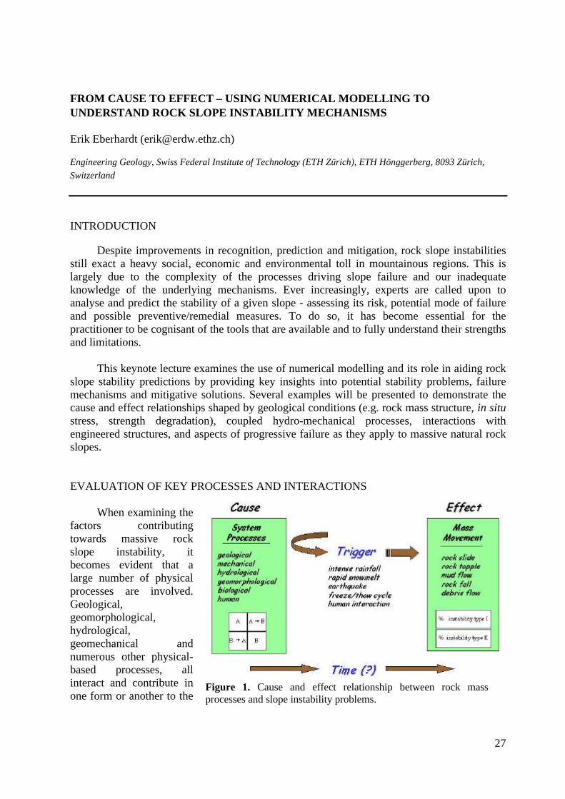
When examining thefactors contributingtowards massive rockslope instability, itbecomes evident that alarge number of physicalprocesses are involved.Geological,geomorphological,hydrological,geomechanical andnumerous other physical-based processes, allinteract and contribute inone form or another to the
Figure 1. Cause and effect relationship between rock massprocesses and slope instability problems.

28
destabilization of the slope. In effect, these processes may be viewed within a system as theresult of a continuous series of events linked through cause and effect relationships (Fig. 1).
After defining the key interactions within the system, consideration must then be given totheir sensitivity to all relevant triggering mechanisms. Slope instabilities may have severalcauses, as defined through the different interacting processes, but only one trigger – an intenseprecipitation event, earthquake or rapid snow melt that causes a near-immediate response in theform of a mass movement (Wieczorek, 1996). In some cases mass movements may occurwithout an apparent trigger due to a variety or combination of physical processes that graduallybring the slope to failure, for example strength degradation through weathering. However, evenin the case of strength degradation in natural slopes, catastrophic failure can still be generallylinked to a triggering event such as a heavy rainfall (Luginbuehl et al. 2002).
Once conceptualized, these system processes and their coupled (or uncoupled)interactions can be integrated into a numerical analysis. It should be emphasized, though, thatelements of field mapping, instrumentation monitoring, in situ measurements and laboratorytesting must also be included if the overall project framework is to move towards the totalassessment or prediction of the rock slope stability state.
NUMERICAL MODELLING OF ROCK SLOPE INSTABILITY MECHANISMS
When undertaking a numerical analysis, the technique chosen depends on both the siteconditions and the potential mode of failure, with careful consideration being given to thevarying strengths, weaknesses and limitations inherent in each methodology (e.g. finite-element, distinct-element, etc.). The quality of the input data made available for the analysismay also vary such that the objectives of the numerical study may take the form of being fullypredictive (i.e. “Class A” prediction or forward modelling of a potential instability) when highquality instrumentation data exists, or in cases where the data is limited, as providing a meansto establish and understand the dominant mechanisms that may affect the behaviour of thesystem. As shown by Coggan et al. (1998), at all times good modelling practice must beexercised.
Focussing on the use of numerical techniques as a means to establish and understand thedominant mechanisms contributing towards the destabilization of the slope, modelling allowsfor the testing of several hypotheses with respect to the measured or expected behaviour of therock slope in question. In the case of geological controls, examples from thinly-bedded dippingrock slopes illustrate the influence of cross-cutting joints in generating the potential fordifferent complex modes of failure (Stead & Eberhardt 1997). The effect of jointing in theanalysis of these problems is often not fully appreciated given the difficulty in mapping theirorientations normal to the slope face. Distinct-element models generated to investigate theseproblems in surface coal mining slopes (Fig. 2), show three different complex failuremechanisms – bilinear, three-hinge buckling and ploughing, as the orientation of the dominantjoint set varies with respect to the dip of the bedding planes. The complexity of these differentfailure modes involves both slip along the controlling discontinuities and plastic yielding of theintact rock material. Furthermore, their sensitivity to initial in situ stress states and differenttriggering mechanisms including pore pressures and seismic loading (Eberhardt & Stead 1998),

29
can only be effectively treated usingdiscontinuum modelling techniques (e.g.distinct-element method).
In these cases, the continuumbehaviour of the intact rock contributes tothe development of the instability in thediscontinuous rock mass. Similarrequirements are necessitated in casesinvolving weak rocks where the instabilitymechanism is related to progressive strengthdegradation, for example through physicaland chemical weathering processes. Recentexperiences from the 1999 Rufi slide,located in the sub-alpine Molassic rocks ofnorthern Switzerland and involving a seriesof interbedded conglomerates and marls,suggest that failure does not occur along thebedding plane contact as has been assumedfor similar slides in the region (e.g. the 1806Rossberg slide at Goldau), but insteaddevelops within the marls and is controlledby the degree of weathering (Luginbuehl etal. 2002). Again, these processes can bemodelled through the utilization ofdiscontinuum-based numerical techniquesthat allow for the consideration of strengthdegradation of the marls (in this case, thecritical system process or “cause”) coupledtogether with increasing pore pressuresbetween weak layers in the marls that servedas the Rufi slide trigger (Fig. 3).
This coupling of complex interactions,e.g. hydro-mechanical behaviour, allows fornumerical models to provide deeper insightsinto slope instability mechanisms but also,in cases where remedial measures areplanned, to better understand how the slopewill respond to different mitigativemeasures before and after implementation.In the latter instance, this can be done byreproducing measured responses providedby surface and subsurface instrumentationas was done for the deep creeping landslideat Campo Vallemaggia in the southernSwiss Alps (Bonzanigo et al. 2001). To
Figure 2. Distinct-element modelling of (fromtop to bottom): bilinear, buckling andploughing complex modes of slope failure.

30
stabilize the slope, a drainage tunnel was constructed but its effectiveness was questioned(despite surface measurements showing that the slope velocities had ceased). This was largelydue to the smaller than expected drainage flow rates and competing arguments that erosion atthe slope’s toe was the primary destabilizing factor. Distinct-element modelling was thereforeperformed to reproduce various in situ measured responses. Results showed that since thegroundwater system primarily involved fracture permeability, and hence storativity was low,significant decreases in pore pressure could be attained though the drainage of only smallvolumes of water (Fig. 4).
FUTURE DEVELOPMENTS
These examples, and others that will bepresented during the keynote lecture, show thatwhen properly applied and constrained, numericalmodelling can significantly assist in the designprocess by providing key insights into potentialstability problems and failure mechanisms. Futurework in this direction is focussing on theapplication of hybrid finite-/distinct-elementanalyses incorporating adaptive remeshing to modelthe progressive development of rock slope failuresurfaces through brittle fracture processes(Eberhardt et al. 2002). An integrated network ofdisplacement, pore pressure and microseismicmonitoring
devices has been installed at a site in southernSwitzerland (Randa), to help in quantifying thespatial and temporal evolution of such processesand to constrain the numerical models. Throughsuch hybrid techniques, modelling will beextended towards modelling the complete failureprocess from initiation, through transport todeposition. Yet, it must always be emphasizedthat numerical modelling is only a tool and not asubstitute for critical thinking and judgement.
REFERENCES
Bonzanigo, L., Eberhardt, E. & Loew, S. (2001).Hydromechanical factors controlling thecreeping Campo Vallemaggia landslide. InKühne et al. (eds.), UEF InternationalConference on Landslides, Davos. 13-22.
Coggan, J.S., Stead, D. & Eyre, J.M. (1998).Evaluation of techniques for quarry slope
drainage adit opened
50 m
50 m
Figure 4. Coupled hydro-mechanicalmodel showing relative slope velocitiesbefore and after construction of drainageadit.
20 m
Figure 3. Analysis of the 1999 Rufislide showing initiation of sliding due toyielding of underlying weathered layers.
yielding of weatheredmarl layers
sliding ofconglomerate blocks

31
stability assessment. Trans. of the Inst. of Mining and Metallurgy - Section B 107: B139-B147.
Eberhardt, E. & Stead, D. (1998). Mechanisms of slope instability in thinly bedded surfacemine slopes. In Moore & Hungr (eds.), Proc., 8th Congress of the IAEG, Vancouver. 3011-3018.
Eberhardt, E., Stead, D., Coggan, J. & Willenberg, H. (2002). An integrated numerical analysisapproach to the Randa rockslide. In Rybáø et al. (eds.), Proc., 1st European Conf. onLandslides, Prague. In Press.
Luginbuehl, M., Eberhardt, E. & Thuro, K. (2002). Primary sliding mechanisms in dippinginterbedded conglomerates and marls. In Rybáø et al. (eds.), Proc., 1st European Conf. onLandslides, Prague. In Press.
Stead, D. & Eberhardt, E. (1997). Developments in the analysis of footwall slopes in surfacecoal mining. Engineering Geology: 46 (1), 41-61.
Wieczorek, G.F. (1996). Landslide triggering mechanisms. In Turner & Schuster (eds.),Landslides: Investigation and Mitigation (Special Report 247). National Academy Press,Washington, D.C., 76-90.

32
SINGLE-EVENT LANDSLIDES RESULTING FROM MASSIVE ROCK SLOPEFAILURE: CHARACTERISING THEIR FREQUENCY AND IMPACT ON SOCIETY
Stephen G. EvansGeological Survey of Canada, 601 Booth Street, Ottawa, Ontario, CANADA K1A 0E8
MASSIVE ROCK SLOPE FAILURE
Landslides resulting from massive rock slope failure (rockslides, rock avalanches andthe failure of volcano slopes (including edifice collapse)) are an important geological hazard inmany regions of the world (Sassa, 1999) and have been responsible for some of the mostdestructive natural disasters in world history (Cornell, 1982).
A wide range of primary processes are involved in catastrophic rock slope failure andreflect the complex interaction between the properties of the materials involved, the geologicalstructure of the rock mass, the geomorphic setting of the event (including slope, relief andposition in a drainage basin), and the nature of stress changes induced by possible triggeringevents. Primary processes include mechanisms of initial failure, the progressive fragmentationof the rock mass and its subsequent rapid movement in which debris may be transported manykilometres away from its source.
Massive rock slope failure frequently results in multiple phase landslides in which, forexample, a disintegrating rock mass involved in an initial rockslide and subsequent rockavalanche becomes transformed into a massive, rapid debris flow which travels well beyondexpected limits (e.g., Casassa and Marangunic, 1993). Massive rock slope failures are oftenassociated with a trigger, a response to a sudden change in geophysical and/orhydrometeorologic variables. They may also occur in response to human forcing.
Secondary processes associated with massive rock slope failure events may themselvesresult in catastrophic consequences. They include landslide-generated waves and displacedwater effects and those processes associated with the formation and failure of landslide dams.Catastrophic secondary effects may be instantaneous or delayed. They extend the impact of arock slope failure in space beyond the boundaries of the primary landslide debris and in timebeyond the timing of the landslide event itself.
Massive rock slope failure is increasingly recognized as an important geomorphicprocess in mountain landscapes (e.g., Densmore et al., 1997).
OCCURRENCE IN TIME; AN ESTIMATE OF GLOBAL HAZARD
Massive rock slope failure occurs with measurable frequency in the mountain regionsof the world. In the Coast Mountains of British Columbia for example rock avalanches, withvolumes in excess of 1 M m3, have occurred every 3.5 years since 1955 (Evans and Clague,1999).
The most recent examples of massive rock slope failure include the earthquake triggeredfailures at Tsao-Ling (120 M m3) and Chiufener-Shan (80 M m3) during the 1999 Chi-Chiearthquake, the extraordinary Zhamulongba rock avalanche (300 M m3)1 in Eastern Tibet
1 Li Tianchi (Personal communication, 2002)

33
which dammed the Yigongzangbu River occurred in 2000, and the Paatuut rock avalanche2 (90M m3) and displacement wave which occurred on the west coast of Greenland also in the year2000. The Yigongzangbu River landslide dam failed 2 months later releasing a massive debrisflow which reached northern India.
A number of studies have analysed time-slice data sets of landslide geometry fromdiscrete triggering events such as heavy rainfall (e.g., Fuji, 1969) and earthquakes (e.g.,Pelletier et al., 1997) or have analysed spatial data sets of (e.g., Hovius et al., 1997) oflandslide geometry. These analyses together with the analysis of well constrained temporalsequences (e.g., Hungr et al., 1999) have shown that despite different triggering mechanisms,landslide styles, tectonic settings, the cumulative frequency-size distribution of landslides in avariety of geologic environments are quite similar and follow a robust power law indicating ascale invariant distribution.
To explore the temporal magnitude and frequency of massive bedrock failure landslidesa data set of massive twentieth century rockslides was assembled. A lower magnitude thresholdvolume was selected as being equal to or exceeding a threshold of 20 M m3, a lower volumethreshold that withstands erosion censoring for the duration of the longest sample interval,10,000 years, the approximate length of the post-glacial period (cf. Whitehouse and Griffiths,1983). The Usoi landslide, which dammed Lake Sarez in 1907, was the largest (2 x 10⁹ m3)non-volcanic rock slope movement of the twentieth century.
For the twentieth century record he world landslide literature as well as a search ofnewspaper indexes (e.g., New York Times Index) has been undertaken in recent years. At least31 rock avalanches over 20 M m3 have occurred in the world in the period 1900-1999suggesting an annual global frequency of massive rock slope failure of at least 0.31, anoccurrence rate of 1 every 3.2 years. This compares to regional data from the European Alpsfor the period 883 to 1987 A.D. (e.g., Abele, 1974; Eisbacher and Clague; 1984) which showsthat 10 rock avalanches with volumes in excess of 20 M m3 occurred during the period 883 to1987, a frequency of occurrence of 1 every 110 years.
The magnitude frequency relation based on cumulative frequency and with landslidemagnitude expressed as volume, for both twentieth century global events and historical Alpinelandslides shows a strong power law relationship. A similar result was obtained for the data ofWhitehouse and Griffiths (1983), a record of rock slope failure in the Southern Alps of NewZealand during the post-glacial period (10,000 years).
Despite widely different geologic environments, different time periods covering threeorders of temporal magnitude (10,000 years /millennium/ and century), a variety of triggeringmechanisms, and uncertainties of volume estimation, the three records show remarkablesimilarity sufficient to suggest a universal magnitude-frequency relation for massive bedrockderived landslides above a threshold volume. The results indicate that massive bedrocklandslides join other styles of landslides and other catastrophic geological processes such asearthquakes and volcanic eruptions in forming orderly empirical magnitude and frequencyrelations that may be of use in assessing the probability of catastrophic events occurring overtime and provides a basis of assessing catastrophic landslide hazard (cf. Hungr et al., 1999).
In evaluating these types of magnitude and frequency data, the upper limiting volumeof massive rock slope failure is provided by the largest subaerial non-volcanic landslidesdocumented on earth including those at Baga Bogd, Mongolia (5 x 10¹⁰m3 ; Philip and Ritz,1999), Green Lake, New Zealand (2.7 x 10¹⁰m3; Hancox and Perrin, 1994), at Saidmarreh, Iran
2 Stig Pederson (Personal communication, 2002)

34
(2.0 x 10¹⁰m3; Harrison and Falcon, 1937). These events provide the maximum crediblelandslide for the analysis of data sets of landslide geometry and are transitional to even greatertectonic-scale gravitational movement (e.g., Worner et al., 2002).
THE RECORD OF LANDSLIDE CATASTROPHES A.D. 1000 – 1999; AN ESTIMATE OFRISK
Following the approach of Evans (1997) an extensive literature search, augmented byarchival research, was undertaken to document the circumstances of the greatest landslidedisasters of the last millennium, A.D. 1000-1999. Here a landslide disaster is defined as asingle landslide events which resulted, either directly or indirectly, in the deaths of 1,000 ormore people. To an extent this criteria is arbitrary, but it is suggested that this death toll issufficiently high that it represents a scientific, administrative, and journalistic reportingthreshold for the millennium.
Data sources included a global data base of landslide disasters related to volcanoescontained in Simkin and Siebert (1994), a less than complete but important global survey of theworld landslide problem edited by Brabb and Harrod (1989), and detailed regional summaries(e.g., Li and Wang, 1992). For the period 1890 –1999 both the New York Times and the TheTimes (of London) Indexes were consulted as were other disaster listings published by theMunich Re-Insurance Company, Office of U.S. Foreign Disaster Assistance, and the UnitedNations Environment Program. 38 landslide disasters that met our criteria, many of them notwidely known, form our global list in which a total about 260,500 deaths occurred during themillennium. The most recent was the rockslide-debris flow, which occurred on the flanks ofthe Casita Volcano, Nicaragua, triggered by heavy rains during Hurricane Mitch in 1998,which resulted in over 2,000 deaths (Scott, 2000).
22 of the 38 events (58%) were directly or indirectly the result of catastrophic rockslope failure (including volcano flank collapse). These events accounted for approximately75% of the total number of deaths in the global record. The five most disastrous single eventlandslides are listed in Table 3; it is noted that 4 of these resulted from massive bedrock failure.
Table 3.DATE COUNTRY LOCALITY SUMMARY LT T DEATHS
1 1786 China Sichuan Landslide Dam on Dadu River LD E 100,000
2 1985 Colombia Nev del Ruiz Lahar V ER 23,000
3 1970 Peru Huascaran Rock avalanche L E 20,000
4 1792 Japan Ariake Sea Landslide-generated wave V ER 15,900
5 1949 Tadjikistan Khait Rock avalanche L E 12,000
The completeness of the global list is subject to three important limitations; (a) despitewhat is considered to be a comprehensive review and an exhaustive literature search, it isrecognized that an unknown number of catastrophes that meet our criteria have not beenreported in historical records. (b) a related uncertainty surrounds a number of known landslidedisasters in which the number of casualties is not definitively known events. (c) in somedisasters, the actual catastrophic process has not been precisely definitely characterized (e.g.,failure of natural dams leading to debris flows or floods).

35
68% (26) of the events took place in Asia, 21 % (8) in South and Central America, and11% (4) occurred in Europe. China has suffered at least 10 landslide disasters (26% of the totaldisaster events) in the millennium resulting in the deaths of about 123,342 people, 47% of thetotal deaths in the record (31) took place in countries that are currently classified as emergingeconomies.
Generation of F/N curves for the global data set suggest a constant risk envelopesimilar in form to that obtained for other geological hazards.
ANALYSIS OF CATASTROPHIC LANDSLIDE EVENTS; IDENTIFICATION OF HIGHHAZARD SCENARIOS
The percentage of the total casualties that resulted from the different types of landslideprocesses was analysed in order to obtain an indication of the destructive impact of massiverock slope failure processes at a global scale.
Surprisingly, a large percentage (68%) of the deaths due to massive rock slope failureresulted from indirect effects of landslides, i.e., the bursting of landslide dams (57%) and theoccurrence of landslide-generated waves (11%). The greatest landslide disaster resulted fromthe bursting of a landslide dam on the Dadu River, China, in 1786 in which as many as100,000 people may have perished downstream (Li and Wang, 1992).
Major landslide disasters are closely associated with earthquakes; over 79% of thedeaths resulted directly or indirectly from earthquake-triggered massive rock slope failure.12% of the total deaths were due to the direct or indirect effects of the flank collapse ofvolcanoes. 25% of the deaths resulted from the direct effects of non-volcanic rock avalanches.
Some landslide disasters occurred at the locations of known previous landslide disasters(e.g., the 1985 event at Nevado del Ruiz (Colombia)) or where evidence of the occurrence ofprevious large-scale landsliding has since been documented (e.g., the events at Mayuyama(Japan) and Huascaran (Peru)) .
Whilst some disasters have occurred without warning, in other disasters onsetconditions have been observed but their significance was either misinterpreted or notrecognised as such. Warnings that could have been given were not issued. Examples are thetragedies at Vajont (1963) and Nevado del Ruiz (1985). In the case of Plane D’Oisans, the1219 A.D. disaster took place as a delayed response to the formation of a landslide dam andimpoundment of a lake, 28 years after the damming landslide event.
It is noted that the death toll from catastrophic landslides is independent of landslidemagnitude; some high casualties have resulted from comparatively modest initial rock slopefailure (e.g. Casita Volcano, Nicaragua, 1998).
CONCLUSIONS
The accumulating evidence that landslide magnitude-frequency relationships formorderly power law relationships is an important advance for hazard assessment in mountainareas. The developing view that massive rock slope failure is an important geomorphic processin the denudation of mountain terrain creates a promising framework for enhanced hazardassessment. Understanding initial failure mechanisms and the correct interpretation ofprecursor signs and identification of onset conditions initiates more site specific hazardassessment as does the prediction and modeling of post-failure behaviour. However, landslides

36
resulting from massive bedrock failure are complex multiphase phenomena that may combineelements of fall, flow and sliding, dramatic volume change during movement, together withstop-start behaviour.
Massive rock slope failure is part of a landscape response system in which convergenceof several factors may lead to a true geomorphic catastrophe. This is the case of excessivefailure and/or entrainment volume, excessive mobility, water displacement (a landslide-generated wave), or a water release event.
Social catastrophes are also seen to a result from the convergence of factors in thelandscape system. The most hazardous scenarios are created by interaction between theseprocesses and are not limited to the impact of landslide debris itself during initial movement,but also due to their secondary effects. The majority of landslide catastrophes are associatedwith other geophysical events (earthquakes, volcanic activity, and heavy rains) and thereforeforms part of a spectrum of geological hazards in terms of vulnerability and risk.
Finally, many of the most significant landslide catastrophes of the last thousand yearsare not well documented. This gap in our knowledge seriously restricts the usefulness of thehistorical record for hazard assessment.
REFERENCES
Abele, G. 1974. Bergstürze in den Alpen, ihre Verbeitung, Morphologie undFolgeerscheinungen; Wissenschafteliche Alpenvereinsheft 25, München, 230 p.
Brabb, E.E. and Harrod, B.L. (Editors). 1989. Landslides: extent and economic significance.A.A. Balkema, Rotterdam.Cornell, J. 1982. The great international disaster book. 3rd. Edition, Charles Scribner, New
York, 472 pp.Cassasa and Marangunic, 1993. The 1987 Rio Colorado rockslide and debris flow, Central
Andes, Chile. Bulletin of the Association of Engineering Geologists, v. 30, p. 321-330.Densmore, A.L., Anderson, R.S., McAdoo, B.G. and Ellis, M.A. 1997. Hillslope evolution by
bedrock landslides. Science, 275, 369-372 (1997).Eisbacher, G.H. and Clague, J.J. 1984. Destructive mass movements in high ountains:hazard
and management. Geological Survey of Canada Paper 84-16, 230 pp.Evans, S.G. 1997. Fatal landslides and landslide risk in Canada; In Landslide risk assessment.
Edited by D.M. Cruden and R. Fell, A.A. Balkema, Rotterdam, pp. 185-196.Evans, S.G. and Clague, J.J. 1999. Rock avalanches on glaciers in the Coast and St. Elias
Mountains, British Columbia. In Slope stability and landslides, Proceedings, 13th
Annual Vancouver Geotechnical Society Symposium, p. 115-123.Fuji, Y. 1969. Frequency distribution of the magnitude of the landslides caused by heavy rain-
fall; Journal of the Seismological Society of Japan, 22; 244-247.Hancox, G.T., and Perrin, N.D. 1994. Green Lake landslide: a very large ancient rock slide in
Fiordland, New Zealand. Proceedings, 7th International Congress, IntaernationalAssociation of Engineering Geology, v. 3, 1677-1689.
Harrison, J.V. and Falcon, N.L. 1938. An ancient landslip at Saidmarreh in southwestern Iran.Journal of Geology, v. 66, p. 296-309.
Hovius, N., Stark, C.P., and Allen, P.A. 1997. Sediment flux from a mountain belt derived bylandslide mapping. Geology, v. 25, p. 231-234.
37
Hungr, O., Evans, S.G., and Hazzard, J. 1999. Magnitude and frequency of rock falls and rockslides along the main transportation corridors of southwestern British Columbia.Canadian Geotechnical Journal, v. 36, p. 224-238
Li , T.and Wang, S. 1992. Landslide hazards and their mitigation in China. Science Press,Beijing, 84 pp.
Pelletier, J.D., Malamud, B.D., Blodgett, T., and Turcotte, D.L. 1997. Scale-invariance of soilmoisture variability and its implications for the frequency-size distribution oflandslides. Engineering Geology, 48: 255-268.
Philip, H. and Ritz, J-F. 1999. Gigantic paleolandslide associated with active faulting along theBogd fault (Gobi-Altay, Mongolia), Geology, v. 27, p. 211-214.
Sassa, K. (Editor), 1999. Landslides of the world. Kyoto University Press, 413 pp.Scott, K.M. 2000. Precipitation-triggered debris flow at Casita Volcano, Nicaragua:
implications for mitigation strategies in volcanic and tectonically active steeplands. InDebris-flow hazards mitigation: mechanics, prediction and assessment. Edited by G.F.Wieczorek and N.D. Naeser, A.A. Balkema, Rotterdam, p. 3-13
Simkin, T. and Siebert, L. 1994. Volcanoes of the World; 2nd. Edition, Geoscience Press,Tuscon, Arizona, 349 pp.
Whitehouse, I.E. and Griffiths, G.A. 1983. Frequency and hazard of large rock avalanches inthe central Southern Alps, New Zealand. Geology, 11:331-334.
Worner, G., Uhlig, D. Kohler, I., and Seyfried, H. 2002. Evolution of the west Andeanescarpment at 18 S (N. Chile) during the last 25 Ma: uplift, erosion and collapsethrough time. Tectonophysics, v. 345, p. 183-198.

38
ESTIMATION OF ENGINEERING GEOLOGICAL CONDITIONS OF AROCKSLIDE DAM OF THE LOWER LAKE ON THE KOLSAI RIVER
Eugene Gaspirovich,"KazHYDRO" Ltd., Almaty, Kazakhstan ([email protected])
The Kolsai river - right tributary of the Chilik river is dammed by two rockslides ... m3
in volume each which form lakes several tens of meters deep. This site is located inKazakhstan in the Kegen district about 300 km south-east from Almaty city. Kolsai rivercrosses northern slope of the Kungei Alatau range with altitudes of a watershed up to 4500 mand forms a U-shape gorge about 500 m deep. Water level in the lake is about 1800 m a.s.l.This region is seismically very active. It was a part of epicentral zone of the catastrophic (M8.3) 1889 Chilik earthquake and was affected by strong seismic motions during the 1887Vernyi, the 1911 Kemin, the 1989 Jalanash-Tup earthquakes. Presumably the Kolsay lakeshave been formed by one of the preceding events.
As far as possible breach of these dams may cause a catastrophic flood in the denselypopulated lower part of the Chilik valley, special measures are required to prevent dam'serosion and destruction. In particular, there is a project of run-off stabilisation through therockslide that dams the lower lake where intensive back erosion affected dam's body composedof debris of Palaeozoic sandstone, tuff-sandstone and tuff-aleurolite. A bench height of presentday waterfall is about 20m.
The project envisage several variants of a ducted spillway which should passroundabout rockslide dam. In its frames engineering-geological investigations have beencarried out, including geological mapping of the site, construction and study of exploratory pitsand adits, in-situ permeability tests and seismic profiling by use of 12-channel seismic station.Some parameters of rockslide debris are cited in the table.
Parameters Rockslide debrisTuff-aleurite Sandstone, tuff-
sandstoneDensity, rs, g/sm3 2,66 2,66Density (in nature), r, g/sm3 2,28 1,89Humidity, W, % 9,4 9,2
Shearing parameters:1. water-saturated soiltgf 0,73 0,82f 36 39Cohesion, C, MPa 0,10 0,132. in naturetgf 0,64 0,83f 33 40Cohesion, C, MPa 0,20 0,25Permeability coefficient, m/24hours 0,12 0,79

39
FAILURE MECHANISMS AND RUNOUT BEHAVIOUR OF THREE ROCKSLIDE-DEBRIS AVALANCHES IN NORTH-EASTERN ITALIAN ALPS.
R. Genevois and P.R. TeccaDepartment of Earth Sciences, University of Padua, Italy .
INTRODUCTION
Catastrophic flow-like mass movements (debris- rock-avalanches) may be identified asmajor landforms in high mountains regions, but little is still known about their distribution,failure mechanisms, travel distances and frequency. These high-energy natural phenomena area major mechanism for overall erosion of the mountain slope and, as they frequently damvalleys, they can be responsible for subsequent disastrous floods. Nevertheless, ambiguousdefinitions of different types still exist and a general inconsistent terminology still affect thescientific literature. M;any words used in this context are old and, when the phenomena beganto be approached in a scientific manner, certain words turned out to be imprecise or evenmisleading in the expression of their meaning.
Recently, Hungr et al. (2001) proposed a more precise definition of terms like “debris flow,debris avalanches and rock avalanches” and a division of the landslide material based ongenetic and morphological aspects. The term “debris avalanche” is proposed to be reserved forlandslides originating in debris, characterised by a rapid shallow flow of partially or fullysaturated material. Rock avalanche are massive, flow-like motion of fragmented rock deriving,then, most of their volume from the failure of any kind of rock (sedimentary, igneous,metamorphic or pyroclastic).
The nature of the physical processes that trigger the instability and the gravitational flow ofrock or debris masses is still poorly understood. These flows, intrinsically transient and nonuniform, exhibit a striking mobility of controversial origin: the correspondingphenomenological models of transport are difficult to constrain and, so, are far from beingpredictive.
The study of rock avalanches requires the physical analysis of two regimes: the quasi-staticand the dynamic, as well as the transition between them. In the quasi-static regime the systemevolves under an external stress state toward a stability threshold which trigger the inset ofmotion of a more or less important volume of material. The understanding of this regime is ofparamount importance since it can allow the identification of possible precursors of theinstability phenomena that are still quite unpredictable. In the dynamic regime, the inertial flowmobilises the system at various depths and is triggered by complex segregation and erosionprocesses over long distances. The analysis of the velocity fluctuations and of the thickness ofthe mobilised layer should allow a better constrains on the validity limits and the pertinence ofthe models.
METHODOLOGY
A comprehensive methodology for rock avalanches analysis has been presented by Coutureet al. (1999). It consists of four steps and it is concerned by the full characterisation of thedetachment (slope failure), the transition (travel path) and the deposition zones, eachcharacterised by different processes.
This methodology has been adopted for the back-analysis of three major rock avalancheslocated in the north-eastern Italian Alps, obtaining so some useful insight into the relationships

40
existing between rock masses properties of the failed slope, model rheologies and depositionprocesses.
After the documentation has been collected and the field work has been carried out, studiesand analyses have focused on:
1) the stability of the original rock slope for the evaluation of the deformation processesand the failure mechanisms. Studies have been performed using a 2-dimensional distinctelement code (UDEC), considering the effects of block size and joint properties on thebehaviour of rock mass and using a modified form of the Hoek-Brown failure criterion(Kumar, 1998), besides the usual Mohr-Coulomb criterion. Block size resulted to controlthe shear strength and the deformational characteristics of the rock masses: closelyjointed rock masses exhibit lower stiffness but higher strength. The parametric studiesgive fundamental information on the rock mass characteristics and boundary conditionsat failure.
2) the fragmentation comparing grainsize distributions in the initial slope and in thedeposition area. The energy of fragmentation has been evaluated by classicalrelationships (Couture et al, 1999) and included in the energy balance equation.
3) the mobility of rock avalanches evaluated by empirical relationships (Scheidegger,1973; Davies, 1982; Corominas, 1996).
4) the post-failure behaviour, that is the runout behaviour and the mechanics of the massmovement, has been inferred back-analysing the information collected with the fieldsurveys by numerical modelling. Existing empirical (Hsu, 1975; Davies, 1982;Corominas, 1996) and numerical models (Sassa, 1988; Sousa and Voight, 1991; Hungr,1995; Rickenmann and Koch, 1997) have been considered for the studied rockavalanches.
Dynamic analyses of the case histories have been performed using the numerical model DAN,proposed by Hungr (1995) and Hungr and Evans (1997), that simulates the flow-like motion ofthe initial landslide and allows also the entrainment of the material along the path. Therheology of the flowing mass has been changed, in the case, to account for the change from dryfrictional (frictional rheology) to velocity-dependent (Voellmy rheology), as a consequence ofthe entrainment of saturated material (Hungr and Evans, 1996).
THE FADALTO ROCKSLIDE/AVALANCHE
The rockslide is situated in the Venetian Pre-Alps at the head of the old Piave River valley.The pre-Quaternary formations outcropping in the landslide area are represented by mesozoicformations: Soccher Limestons ( micritic limestones with thin clayey and marly interstrata) andthe overlying Fadalto Limestones (bioclastic calcarenites and calcirudites) make a gentleanticline with the layers dipping towards the valley bottom (25°). The rock mass is interested,besides the stratification (N300°-25° W) by three joints systems approximately perpendicularto the stratification. The rock mass results subdivided into blocks from some cubic decimetersto a few cubic meters.
The morphology of the valley results, besides the geomorphological processes, from acomplex combination of tectonic, fluvial and glacial factors: the valley is, in fact, locatedalong an important regional dislocation range and its form has been determined by the activityof Neogenic rivers and of Pleistocenic glaciers. The valley has a local N-S direction and thegreat scar of the rockslide, in the left side, runs E-W in the northern part and, prevaingly N-S inthe central part.

41
The Fadalto landslide occurred over different phases. The main rockslide is of the Late-Glacial period, connected then with the deglaciation. The debris mass dammed the valley and
diverted, since then, the river into a lateral pre-existing valley. Further landslides, mainly of therockfall type, happened around 4000-5000 years B.P., in correpodence with the hot-humid“climatic optimum” of the Upper-Atlantic.
The total volume of the rockslides/rockfalls, estimated by reconstruction of the originalslope, is of about 2.8x10⁸ m3 . The fragmented rock slide blocks and debris filled up the valley,
run up the opposite slope at adistance of 850-900 m leaving a 80-100 m deep trench with the sourceslope. The area of the slide deposit isabout 1.9 x10⁶ m2, but the volume ofthe debris is difficult to evaluateexactly. Assuming a bulkingcoefficient of only 20%, thefragmented rock deposit should beapproximately 3.4x10⁸ m3 and itshpoud have a mean thickness ofabout 180 m. The apparent frictionangle is 33°.
The parametric stability analysis ofthe reconstructed slope profile,carried out using a bi-dimensionaldistinct element code (UDEC),pointed out the weight of theboundary conditions in the slopefailure and in particular: i) thenecessity of earthquake-induced

42
cyclic stresses; ii) the presence of high water pressures on the slip surface consistent with theclimatic conditions; iii) the effect of the stress release consequent to the glacier retreat.
A numerical model (DAN), simulating the flow-like motion of the initial landslide andallowingthe entrainment along the path of material with different behaviour, has been used todescribe the dynamics of the rockslide (Hungr, 1995; Hungr and Evans, 1997). The slidestarted as a frictional material and the transition to Voellmy material was made at a distance ofabout 300 m at the beginning of the alluvial material of the valley bottom.
The model seems to satisfactory simulate the dynamics of the slide and the morphology of thedebris deposit.
The “Masiere di Vedana” Rock Avalanche This landslide is located on the northern slope of the “Belluno Great Valley” (Southern Alps).The slide originated on the southern slope of Mt. Peron (1486 m a.s.l.) and it moved along thevaley in southern direction. The origin of the rock avalanche is a slope, angled 50-70°, composed of a sequence of marly,calcareous and dolomitic formations, ranging from the Triassic to the Eocene-Oligocene, thestrata deeping almost vertically. Rock toppling or falls are considered the main failuremechanisms. The volume of the slided mass has been estimated as 8.5-9.0x10⁷ m3 .The landslide debris extend for a distance from the crown of 5.5 Km with a mean slope of 2.5-3.0%. The apparent friction angle is about 9°. The study of the natural and artificial sectionsshows: i) at the the surface the avalanche debris consists, for a tickness of about 20 m, of largefragments and blocks, up to some meters in diameter, set in a scanty sandy-gravelly matrix; the
Ele
vatio
n, m
m x 10
DTM of the “Lavini di Marco” Rockslide

43
homegeneous distribution of different lithologies in different areas indicates the retrogressivenature of the landsliding sequence; ii) below and in the more distal deposit area, a 10 m thickavalanche debris is present, apparently made up of only one lithology; iii) the avalanchesdebris lie on the glacial and fluvio-glacial würmian deposits and, somewhere, on pre-würmianconglomerates sometimes with the interposition of a palaeosol of some decimeters thick; iv)the bedrock is represented by miocenic marls; v) the estimated volume of the debris deposits is1.1-1.2x10⁸ m3, corresponding to a mean bulking coefficient of 30-35%.
The back-anaòysis carried out with the distinct element code UDEC showed that topplingand/or falls are the most likely mechanism of failure, but in presence of high pore waterpressures and stress release due to the glacier retreat.
Dynamic analyses using the numerical model DAN show that the great distance reached bydebris on a so little slope is the consequence of their running over the glacier.
THE “LAVINI DI MARCO” ROCKSLIDE
This landslide is located on the left slope of the Adige River valley (Southern Alps). Theslope concides with the bedding of the lower member of a calcareous formation, sloping 23° asa mean, characterised by some thin clayey-marly strata. All the western slope of the ColliZugna Mt. show the presence of many large ancient rockslides/avalanches.
The considered rockslide involved the slope from 1450 m to 250 m a.s.l. for a length of 4000m and a maximum width of 900 m. The thickness has been evaluated in approximately 40-45m resulting in a volume of abaout 9.0-10.0x10⁷ m3 .
The corresponding debris deposit spread out on the valley floor with an area ofapproximately 3.2X10⁶ m2 and an estimated volume of about 4.0-4.5x10⁷ m3 . Considering abulking coefficient of only 20% the volume of debris that should be buried in the alluvium isapproximately 6.5-8.5x10⁷ m3 , correspondig to a depth of 20-25 m below the actual valleyfloor. The apparent friction angle results 12°.
The Udec analyses showed the rockslide originated by the neo-tectonic activity of the Post-Glacial period as regard both the trigger (earthquake) and the pre-failure deformationmechanisms. In particular, a buckling failure mode (Hoek and Bray, 1977; Hu and Kemfert,1995) has been envisaged as the most probable and the calculation illustrates the gradualfailure process of the slope during the glacier retreat.
The dynamic analysis with Dan besides indicated the importance of rapid loading on alluvialdeposits relative to the rock avalanche mobility.
REFERENCES CITED
COROMINAS J. (1996): The ngle of reach as a mobility index for small and large landslides.Can. Geotech. J., Vol. 33, pp. 260-271.
COUTURE R., EVANS S.G., LOCAT J., HADJIGEORGIOU J &ANTOINE P. (1999): Aproposed methodology for rock avalanche analysis. In: Slope Stability Engineering, Ed.Yamagami & Jiang, pp. 1369-1378, Balkema.

44
DAVIES T.R. (1982): Spreading of rock avalanche debris by mechanical fluidisation. RockMechanics, Vol. 15, pp. 9-24.
HSU K.J. (1975): Catastrophic debris steam (sturzstroms) generated by rock falls. Bull. GeolSoc. America,Vol. 86, pp. 129-140.
HOEK E. & BRAY J.W. (1981): Rock Slope Engineering. Institution of Mining andMetallurgy, London, pp. 358.
HU Y. & KEMFERT H.G. (1999): Numerical simulation of the buckling failure in rock slopes.Slope Stability Engng., Yagi, Yamagami and Jiang Ed., pp.349-354.
HUNGR O. (1995) : A model for the runout analysis of rapid flow slides, debris flows andavalanches. Can. Geotec. J., Vol. 32, pp. 610-623.
HUNGR O. & EVANS S.G. (1996): Rock avalanches runout prediction using a dynamicmodel. Proc. 7th Int.Symp. Landslides, Trondheim, Vol. 1, pp. 233-238.
HUNGR O. & EVANS S.G. (1997): A dynamic model for landslides with changing mass.Proc. IAEG Int. Symp. Engng. Geology and Environment, Athens, Vol. 1, pp. 719-724
HUNGR O., EVANS S.G., BOVIS M.J. & HU8TCHINSON J.N. (2001): A Review of theClassification of Landslides of the Flow Type. Environmental & Engineering Geoscience,Vol. VII, No.3, pp. 221-238
KUMAR P. (1998): Shear Failure Envelope of Hoek-Brown Criterion for Rockmass.Tunnelling and Underground Space Technology, Vol. 13, No.4, pp. 453-458.
RICKENMANN D. & KOCH T. (1997): Comparison of debris flow modelling approaches.Proc. 1st Int. Conf. Debris-flow Hazard Mitigation, A:S:C:E:, San Francisco, pp. 576-585.
SASSA K. (1988): Geotechnical model for the motion of landslides (Special Lecture). Proc.5th Int. Symp. On Landslides, Vol. 1, pp. 37-56.
SCHEIDEGGER A.E. (1973): On the prediction of the reach and velocity of catastrophiclandslides. Rock Mechanics, Vol. 5, pp. 231-237.
SOUSA J. & VOIGHT B. (1991) : Continuum simulation of flow failures. Geotechnique, Vol.41, pp. 515-538.
4.0-4.5x10⁷ m3 .

45
EDOARDO SEMENZA (1927-2002): IMPORTANCE OF GEOLOGICAL ANDGEOMORPHOLOGICAL FACTORS FOR THE IDENTIFICATION OF THEANCIENT VAIONT LANDSLIDE
Monica GhirottiDepartment of Earth and Geo-Environmental Sciences, Alma Mater University of Bologna,Italy
During his last years of life, Prof. Edoardo Semenza (1927-2002) decided to look backover the history of the 1963 Vaiont landslide through unpublished documents and picturesfrom 1958 to 1963. The Vaiont disaster exerted a great influence the world over, and inparticular both in the field of civil engineering and engineering geology. His special issue isrepresented by the publication of the book "La storia del Vajont raccontata dal geologo che hascoperto la frana" (The history of Vaiont narrated by the geologist who identified thelandslide). This work summarizes the events that preceded and accompanied the constructionof the dam and the functioning of the reservoir, his researches and interpretative studies on theVaiont valley, together with some new hypotheses to explain what could have happened untilOctober 1963.
The knowledge of the local geology and of its potential risk was, at that time, strictlyrelated to decisional choices of electrical companies. The problem of the Vaiont reservoir slopestability was entrusted to E. Semenza for the geologic study. Edoardo Semenza’s detailedgeological and geomorphological survey led to the identification, already in 1959, of variousancient landslides. Only one of these was recognised as potentially dangerous: the one on theleft side, slightly upstream of the dam. The main results of his studies, years before the firstmovements, were the following:
1) an enormous ancient landslide had slid down the north side of Monte Toc; thelandslide deposits had filled the valley bottom where the Vaiont River ran after the last glacialretreat;
2) the new cutting of the Vaiont gorge by its stream had then divided the big slide massinto two parts: the main portion remained on the left side of the valley, while a little mass waspreserved on the right side. This last landslide deposit was clearly distinguishable from theregular in situ rock-mass and was consequently called "Colle Isolato" (Isolated Hill) by E.Semenza;
3) the left side of the Vaiont valley had a «seat» shaped structure, which is still clearlyvisible on the steep eastern slope of the Piave Valley, in front of Longarone. This structurecorresponded to the lower part of the southern side of a syncline, whose axial plane isapproximately flat and slightly dipping towards the east in the Vaiont valley;
4) at that time, E. Semenza thought that the ancient landslide had taken place on a moreor less cylindrical failure surface, bounded by an outcrop of mylonites at 600 m asl and an east-west elongated depression area at an altitude of approximately 850 m asl.
6) the front of the old landslide mass had a very undisturbed appearance; this featurehindered the unanimous recognition of the ancient landslide for some time.

46
Together, these geological and morphological features demonstrating the existence of anancient landslide and its large dimensions, led E. Semenza to the formulation of the hypothesisthat the mass in question could have moved again during the filling of the reservoir.
The main interpretative studies of this landslide, always subject to research anddiscussion, are based on Semenza‘s hypothesis.
E. Semenza, in his last papers, through the revision of the events prior to the Vaiontdisaster, had concluded that, although in the valley old landslips had been identified, their fullsignificance was not understood at the time. “Only a careful observation and a detailedgeological survey both of the northern slope of Monte Toc, (which before 1963 and to this dayremains unfolded and scarcely disturbed) and of the “Colle Isolato” area, could have givengeologists the possibility of making a more correct interpretation of the complex phenomena.Furthermore, insufficient investigation and field work was carried out prior to thecommencement of the dam/reservoir project.”
The Vaiont landslide has been the subject of much research and discussion and more thanthirty years later, many questions are still open and a source of stimulus for many researchers.Edoardo Semenza’s strongly believed both in the role of geology and geomorphology asfundamental support to any engineering project and in the importance of a goodcommunication between the various specialists working on large projects.

47
A FRACTURE-BASED CRITERIA TO ASSESS ROCK-MASS SUSCEPTIBILITY TOFAILURE
Edwin L. HarpU.S. Geological Survey
INTRODUCTION
Rock falls and rock slides from steep slopes in fractured and jointed rock present anincreasing hazard to people and property due to the accelerating pace of urban developmentthroughout the world. Although a commonplace occurrence in most severe rainfall events,their numerical dominance is fully realized in seismic events where they comprise the greatestfraction of all types of landslides (Keefer, 1984; Harp and others, 1981, Wilson and Keefer,1985; and Harp and Keefer, 1990). In the M 6.7 Northridge, California, earthquake of 1994,more than 11,000 individual landslides were documented, of which greater than 90% were rockfalls and rock slides (Harp and Jibson, 1996).
The failure process in fractured rock is complicated. The failure and movement ofrock, whether triggered by seismic or climatic event, generally includes several failure modes.Toppling, tensile failure, and shear displacement may occur simultaneously. These processescan be modeled on a site-specific basis with finite element or other numerical methods, butsuch methods are not feasible for areas that are regional in scale or for linear corridors ofinterest. To assess the rock-failure hazard over an entire mountain slope or on a regional basis,an empirical method is needed that will permit numerous stability estimates throughout a largearea.
THE USE OF EMPIRICAL METHODS ON A REGIONAL SCALE
Various empirical methods have been formulated to describe the susceptibility of rockslopes to failure. Selby (1980) examined the qualitative relation between rock properties andslope steepness. He used intact rock strength, weathering, joint spacing, joint orientation, jointwidth, joint continuity, and outflow of ground water to estimate the slope-supporting capabilityof rock. Each of his parameters is rated numerically and the values combined to yield a scorethat rates a rock’s potential for supporting a steep slope.
Standard methods for quantitatively describing discontinuities in rock were detailed byBarton (1978). Numerical rating factors include orientation, spacing, persistence, roughness,wall strength, aperture, filling, seepage of water, number of discontinuity sets, and block size.Barton and others (1974) presented a technique for combining six factors or characteristics ofrock discontinuities to calculate an index called rock mass quality, or Q. The six factors areRQD, the rock quality designation (Deere, 1963), Jn, the joint set number, Jr, the jointroughness number, Ja, the joint alteration number, Jw, the joint water reduction factor, and SRF,the stress reduction factor. These six factors are combined to yield a number that reflects therock-mass stability of the slope in question according to the following equation.

48
Q = (RQD/Jn) x (Jr/Ja) x (Jw/SRF) Eq. 1
Increasing values of Q correspond to increasing rock-mass stability.
ROCK MASS QUALITY AS AN INDICATOR OF SLOPE STABILITY
Rock mass quality is used as an engineering classification for the initial design oftunneling support and cost estimation in mining. It has been extensively correlated with roofsupport pressures in rock and required span widths for tunnels and mines (Barton and others,1974). Because Q-values depend on fracture characteristics affecting the stability of rockslopes, it was clear that a modification of Q might provide a useful parameter to rate the failurepotential of rock slopes.
Of the factors used to evaluate Q, all but SRF could be used in their original form. SRFrelates to the potential for fractures to open once excavation has taken place due to high stressat great depths. This is generally not the case at the surface, so SRF has been modified toevaluate the tendency of rock slopes at the surface to loosen during seismic or climatic events.This factor now reflects the openness of near-surface fractures in slopes and the orientation ofpervasive fractures with respect to the slope face. The factor has been renamed aperturefracture, or AF. This factor is the most important factor determining the failure susceptibilityof rock slopes, especially in seismic events.
Each of the six factors comprising Q is evaluated by comparing rock outcrops todescriptive tables containing numeric scores. Once each of the factors has been evaluated andscored, Q is calculated according to equation 1 with AF replacing SRF. The first application ofthis method was in the eastern Sierra Nevada mountains near Mammoth Lakes, Californiawhere a sequence of four ~M 6.0 earthquakes triggered thousands of rock falls and rock slidesin the Mammoth Lakes area (Harp and Noble, 1993).
CORRELATION OF Q WITH SEISMICALLY-INDUCED ROCK-FALLS
The May 25-27, 1980, earthquake sequence in Mammoth Lakes, California, triggeredseveral thousand landslides throughout an area of approximately 2,500 km2. The series of fourearthquakes had magnitudes of 6.0 or greater. The landslides triggered were almostexclusively rock and rock slides that ranged in size from just a few small rocks to more than200,000 m3 (Harp and others, 1984). To determine a relationship between Q and the spatialconcentration of rock falls, 92 rock-fall sites throughout the area were visited to measurefracture characteristics and calculate Q-values.
When the number of rock falls within a site area (170 m radius) were plotted against Q-values, an exponentially decreasing data envelope was observed ranging from more than 12rock falls at the lowest Q-values to 0 at Q-values greater than 10. This data set was subjectedto a probability analysis resulting in an exponential function of number of rock falls versus Qthat predicts the mean number of rock falls per site for a given Q-value. The analysis alsoallowed the separation of the Q-values into several levels of susceptibility ranging fromextremely high to low.

49
APPLICATION OF Q-VALUES TO ROCK-FALL PROBLEM IN NAVAJO NATIONALMONUMENT
Navajo National Monument in northeastern Arizona contains three extensive andspectacular cliff dwellings that are accessed by the public via foot trail. The Aspen Forest Trailto Betatakin Ruins experienced sporadic rock falls after initial construction in 1963. In 1982,the trail was widened by blasting in a section where the trail crossed a near-vertical section ofcliffs. The widening of the trail created an overhanging section in the Navajo sandstone, amassive, cross bedded, reddish colored sandstone of Jurassic age. Following the widening in1982, two rock falls of several hundred cubic meters volume occurred that resulted in thecollapse of a 20-m length of cliff face immediately above the trail in the overhanging section.The trail was heavily damaged, and continuing rock fall presented a hazard to the public ingaining access to the cliff dwellings by this trail. Since these rock falls in 1982, the trail hasbeen repaired but has remained closed to the public.
In 2000, a request was received from the National Park Service to the U. S. GeologicalSurvey to evaluate the present stability of the steep cliff sections of the Aspen Forest Trail.Subsequently, a rock-mass-quality analysis of the steep sections of the trail was undertaken toassess the relative susceptibility of the cliffs above the trail to rock fall and the possibility ofreopening the trail to the public. The measurement of fracture characteristics and calculationof Q-values clearly revealed the weakest sections of the cliffs above the trail and those mostsusceptible to future rock fall. The analysis showed that, not only was the section of cliff thatfailed in 1982 extremely susceptible to ongoing rock fall, but another section just 60 m to thewest that had not previously failed also had equally low Q-values indicating similarsusceptibility (Wieczorek and Harp, 2000).
ANOMALOUS ROCK-FALL CONCENTRATIONS IN PACOIMA CANYON TRIGGEREDBY THE 1994 NORTHRIDGE, CALIFORNIA EARTHQUAKE
The January 17, 1994 Northridge, California, earthquake (Mw 6.7) triggered more than11,000 landslides over an area of about 10,000 km2 (Harp and Jibson, 1996). Greater than90% of these landslides consisted of rock falls and rock slides that were concentrated in an areaof about 1,000 km2 that lies north and northwest of the epicenter in the Santa SusanaMountains and the mountains north of the Santa Clara River. Landslides were more sparselyscattered throughout the remainder of the region with one notable exception: Pacoima Canyonon the southern flank of the San Gabriel Mountains produced a dense concentration of rockfalls that was anomalous with respect to the surrounding area. Interestingly, Pacoima Canyonlikewise produced anomalously high concentrations of rock falls in the 1971 Mw 6.7 SanFernando earthquake (Hauksson, 1995).
To investigate these anomalous rock-fall concentrations, the rock slopes in PacoimaCanyon and in four adjacent canyons were sampled and fracture properties measured tocalculate Q-values. A comparison of the Q-value ranges between the five different areasshowed no significant differences in the rock-fall susceptibilities of the slopes in the five areas(Harp and Jibson, in press). By eliminating differences in susceptibility as the cause of theanomalous failure concentrations in Pacoima Canyon, the most likely explanation isamplification of seismic shaking by topography. This possibility is also supported by strong-motion records that show 1.59 g peak acceleration on the narrow ridge that forms the abutment

50
of Pacoima Dam as compared to 0.44 g peak accelerations both at the Pacoima Damdownstream site at the foot of the dam and on nearby Kagel Mountain.
SUMMARY
The previous applications of the rock-mass-quality method of analysis to depict therelative susceptibility of rock slopes and to lend insight into the behavior of rock slopes inseismic events illustrate its past usefulness. Future applications to address the mapping ofrock-failure hazards and to answer questions regarding the importance of rock-slopesusceptibility in the distribution of failures from a seismic or climatic event are obvious. Yetother uses of the method may arise by modifying one or more of the factors to more accuratelydescribe certain aspects of the rock-failure process that are of critical importance to individualsituations.
REFERENCES
Barton, N. (Coordinator), 1978, Suggested methods for the quantitative description ofdiscontinuities in rock masses: International Journal of Rock Mechanics and MiningSciences and Geomechanics Abstracts: International Society for Rock MechanicsCommission on Standardization of Laboratory and Field Tests, v. 15, no. 5, p. 319-368.
Barton, N, Lien, R., and Lunde, J., 1974, Engineering classification of rock masses for thedesign of tunnel support: Norwegian Geotechnical Institute, Oslo, Norway, 48 p.
Deere, D. U., 1063, Technical description of rock cores for engineering purposes:Felsmechanik und Igenieugeologie, v. 1, no. 1, p. 16-22.
Harp, E. L., and Jibson, R. W., in press, Anomalous concentrations of seismically triggeredrock falls in Pacoima Canyon: Are they caused by highly susceptible slopes or localamplification of seismic shaking?: Seismological Society of America Bulletin, 18 p., 8 figs.
Harp, E. L., and Jibson, R. W., 1996, Landslides triggered by the 1994, Northridge, California,earthquake: Seismological Society of America Bulletin, v. 86, no. 1B, p. S319-S332.
Harp, E. L., and Keefer, D. K., 1990, Landslides triggered by the earthquake, in Rymer, M. J.,and Ellsworth, W. L., eds., The Coalinga, California, Earthquake of May 2, 1983: U. S.Geological Survey Professional Paper 1487, p. 335-347, 1 pl.
Harp, E. L., and Noble, M. A., 1993, An engineering rock classification to evaluate seismicrock-fall susceptibility and its application to the Wasatch Front: Bulletin ofthe Association of Engineering Geologists, v. XXX, p.293-319.
Harp, E. L., Wilson, R. C., and Wieczorek, G. F., 1981, Landslides from the February 4, 1976,Guatemala earthquake: U. S. Geological Survey Professional Paper 1204-A, 35p. 2pl.
Hauksson, E., 1995, Seismological overview of the 1994 Northridge earthquake sequence inCalifornia, in Woods, M. C., and Seiple, W. R., eds., The Northridge, California,Earthquake of 17 January 1994: California Department of Conservation, Division of Minesand Geology Special Publication 116, p. 17-38.
Keefer, D. K., 1984, Landslides caused by earthquakes: Geological Society of AmericaBulletin, v. 95, p. 406-421.
Selby, M. J., 1980, A rock mass strength classification for geomorphic purposes: With testfrom Antarctica and New Zealand: Zeitschrift fur Geomorphologie, v. 24, no. 1, p. 31-51.

51
Wieczorek, G. F., and Harp, E. L., 2000, Rock-fall hazard assessment of the Aspen ForestTrail, Navajo National Monument, Arizona: U. S. Geological Survey Open-File Report 00-305.
Wilson, R. C., and Keefer, D. K., 1985, Predicting areal limits of landsliding, in Ziony, J. I.,ed., Evaluating Earthquake Hazards in the Los Angeles Region-An Earth SciencePerspective: U. S. geological Survey Professional Paper 1360, p. 317-345.

52
ROCK AVALANCHING IN THE NW ARGENTINE ANDES AS A RESULT OFCOMPLEX INTERACTIONS OF LITHOLOGIC, STRUCTURAL ANDTOPOGRAPHIC BOUNDARY CONDITIONS, CLIMATE CHANGE AND ACTIVETECTONICS
Reginald L. Hermanns1), Ricardo A. Alonso2), Luis Fauque3), Susan Ivy-Ochs4), Peter W.Kubik4), Samuel Niedermann1), Manfred R. Strecker5), and Arturo Villanueva Garcia6)
1) GeoForschungsZentrum Potsdam, Germany2) Universidad de Salta, Argentina3) Instituto de Geología y Recursos Minerales, Buenos Aires, Argentina4) Institut für Teilchenphysik, ETH Hönggerberg, Zurich, Switzerland5) Geowissenschaftliches Institut, Universität Potsdam, Germany6) Faculdad de Ciencias Naturales, Tucumán, Argentina
ABSTRACT
In NW-Argentina satellite image interpretation, airphoto analysis, and structural,stratigraphic and sedimentologic field studies including tephrostratigraphy combined with 14Cradiometric, and cosmic ray exposure dating provides a better understanding of factorscontrolling the spatial/temporal distribution of rock avalanching in this tectonically activeregion. Large mountain-front collapses occur in two geomorphic settings in NW Argentina: A)narrow valleys draining large basins, and B) mountain fronts bordered by wide piedmont areas.While the deposits in the narrow valley environments are late Pleistocene and Holocene in ageand were generated during humid climate periods, those in the piedmont regions aresignificantly older and do not have obvious relations with climate change. Common to theregional distribution in both settings is the influence of lithology, slope angle and structuralcontrols. Rock avalanches only occurred in granites, low-grade metamorphic rocks and coarseclastic sedimentary rocks. These lithologies are competent enough to form steep slopes andprovide continuous planar structures such as bedding planes, exfoliation joints, and cleavagesthat dip toward the valley at most sites. Affected ranges have relief contrasts larger than 400 mand slope angles are always steeper than 20°. Because all rock avalanches originated in thehangingwall of reverse faults with important Neogene and Quaternary displacement, mostslides are interpreted to have been triggered seismically. However, only at a few sites detailedstratigraphic and sedimentologic studies of related sediments allow to unequivocally show thatseismicity represents the only possible trigger mechanism for landsliding or, alternatively thatstrong seismic rupture at mountain fronts and landsliding occurred nearly coevally.
INTRODUCTION
Topographic conditions, which favor giant mountain-front collaps are often either relatedto lateral fluvial undercutting (e.g. Dethier & Reneau 1996) and/or valley-wall oversteepeningby glacial erosion (Evans & Clague 1994); both mechanism can be enhanced due to climaticchange towards warmer or more humid conditions or are related to repeated tectonic uplift andstructural weakening of mountain fronts. In general, mountain-front collaps is favored by acombination of both. In addition, large mountain-front collapses have been triggered by a
53
variety of mechanisms including, long lasting rainfalls and/or rapid snow melt, volcaniceruptions and strong seismicity. Based on our observations in the NW Argentine Andes thissystematic study focuses on how these different processes act in varying geomorphic settingsof a mountain belt on the temporal and regional distribution of giant slope failures.
The Puna Plateau, the northwestern Sierras Pampeanas and the southern part of theCordillera Oriental of NW Argentina represent an ideal natural laboratory for such a studybecause of the arid climate conditions providing a high preservation potential for avalanchedeposits. Furthermore, these conditions and the high elevations also allow to apply cosmogenicnuclide dating to Quaternary landforms and deposits. In addition, due to the proximity to thevolcanically active Central Andes, abundant tephra horizons serve as stratigraphic markers forcorrelation purposes.
Here we summarize previously published data (Fauque & Strecker 1988, Hermanns &Strecker 1999, Strecker & Marrett 1999, Hermanns et al. 2000, Trauth et al. 2000, Hermanns etal. 2001, Hermanns et al. 2002, Hermanns et al. in press). In addition, we include new aspectson seismically deformed lake sediments, which are associated with a large rock avalanche,indicating a possible seismic trigger mechanism.
GEOLOGIC SETTING
The Puna Plateau and the northwestern Sierras Pampeanas are characterized by reverse-fault bounded ranges and intervening basins composed of late Precambrian-Palaeozoic low- tohigh-grade metamorphic rocks and Palaeozoic granites (e.g. Rapela 1976) and Tertiary toQuaternary basin-fill deposits (e.g. Strecker et al. 1989). The Cordillera Oriental is a fold andthrust belt of Precambrian basement and overlying unmetamorphosed Cambrian to Tertiarysediments (e.g. Mon 1976), and it is cut by deeply incised valleys connected to the foreland.Because of its position west of the eastern Subandean ranges, that reach altitudes of >3000 m itis protected from the moisture-bearing winds from the Atlantic and is therefore characterizedby arid climatic conditions since the late Tertiary (Kleinert & Strecker 2001). Whereantecedent rivers cross these uplifting ranges, rock-avalanche deposits are often associatedwith lacustrine and terrace deposits; all of these deposits commonly contain tephra (Hermanns& Strecker 1999, Trauth & Strecker 1999).
Historic seismicity records of the past 200 years (Castano 1997) and instrumentallyrecorded seismicity of the past 38 years (Engdahl et al. 1998) indicate that this region ischaracterized by low frequency, low to medium magnitude earthquakes. Frequent earthquakesin this region occur only along two structures within the Puna Plateau. In the rest of the easternCentral Andes stronger seismicity is located east of the working area in the Santa Barbaraprovince, which is the eastern deformation front of the Central Andes, or farther south in thecentral Sierreas Pampeanas.
METHOD
Landslide deposits were first located using Landsat TM imagery, using spectral bands 5,4, and2. Typical recognition criteria include lobate forms in piedmont environments and spectralcontrasts to valley deposits in narrow valley environments where lobate morphologies could

54
not be attained due to a restricting topography preventing long run-out distances. In a secondstep, the inferred landslide origin of these deposits was verified on stereopairs of aerialphotographs, which further helped to constrain landslides of different ages based on surfacemorphology. Finally, about 90% of the landslide sites were visited in the field to characterizebreakaway scarps in detail, to investigate the stratigraphic relations with adjacent deposits, andto take surface samples for cosmogenic nuclide dating, volcanic ashes for tephrochronologiccorrelations, and organic material for radiocarbon dating (for details on cosmogenic nuclidedating see Kubik et al. 1998, Hermanns et al. 2001, and references therein; fortephrochronology and radiometric 14C dating see Trauth & Strecker 1999, Hermanns et al.2000).
RESULTS
Detailed topographic, lithologic, structural and neotectonic descriptions of rock-avalanche sites are reported in Fauque & Strecker 1988, Hermanns & Strecker 1999, Strecker& Marrett 1999 and Hermanns 1999. Stratigraphic assessments of the rock-avalanche sites andage determinations are given in Trauth & Strecker 1999 and Hermanns et al. 2000. Additionalages of landlides are reported in Trauth et al. 2000 and Hermanns et al. 2002. These dataindicate that landslides in narrow valleys appear to have clustered in two time periods between40 and 25 ka and after 5 ka while rock-avalanche deposits along mountain-fronts boardered bywide piedmont regions are significantly older; e.g. eight superimposed landslide deposits onthe western Sierras Laguna Blanca piedmont have 21Ne exposure ages between 150 and 430 ka.
A new 10Be exposure age for the breakaway surface of a rock-avalanche deposit in theLas Conchas valley at the south face of Cerro Zorrito indicates that this event happened about4.5 +/- 0.5 ka ago. This age is important because the rock avalanche fell into a lake (Hermanns& Strecker 1999) which according to a new AMS 14C age of organic material existed at leastsince 7.50 +/- 0.07 ka. Two thrust-fault offsets within lake sediments and two seismitehorizons indicate that strong seismicity must have occurred in the vicinity of the collapsedmountain front. In addition, buckle folds in the footwall of this fault and slump folds in thehangingwall indicate that lake sediments reacted with ductile behaviour during the inferredseismic event and were still water-saturated. These observation indicate that both earthquakesoccurred during the lake phase and hence within the same time frame as landsliding.
DISCUSSION AND CONCLUSIONS
The distribution of rock avalanches in the northwestern Argentine Andes clearly showsthat they were not generated randomly. Instead, deposits are found in clusters along sectors ofmountain fronts representing distinct topographic, lithologic, and structural characteristics.The source area of rock avalanches in this environment has two topographic constraints: (1)vertical relief contrasts between the top of the breakaway zone and the foot of the mountainfront must exceed a threshold of 400 m, and (2) the slope inclinations must be steeper than 20°.Rock avalanches are restricted to three types of lithology: granites, low-grade metamorphicrocks, and coarse clastic sedimentary rocks. These rock types provide anisotropies such asbedding planes, exfoliation joints, cleavage, and minor faults, that dip toward the valley at allvisited sites and act as breakaway and sliding surfaces (Hermanns & Strecker 1999). Inaddition, all rock avalanches occurred in the hangingwalls of active thrust or reverse faults (e.g.Hermanns et al. 2001).

55
Two morphologic settings for rock avalanches can be distinguished in northwesternArgentina deeply incised, narrow valleys draining large catchment areas, and mountain frontsbordered by broad piedmont regions far away from the effects of trunk streams (Hermanns etal. 2000). Landslides in the narrow valleys appear to have clustered in two time periodsbetween 40 and 25 ka and after 5 ka. These clusters correspond to periods characterized bymore humid climate conditions in northwestern Argentina (Trauth et al. 2000). In addition,during these climatic periods (Minchin and Titicaca, respectively) the combined effects of ElNiño/Southern Oscillation (ENSO) and tropical Atlantic sea-surface temperature dipole havebeen active in subtropical South America (Trauth et al. 2000). However, there are exceptions,as in the Quebrada del Tonco where a cluster of coeval landslides occurs at about 7 ka. Thestratigraphic relations of these landslide deposits overlying in direct contact a tephra bed showthat strong rainfall or sustained humid conditions are unlikely to have triggered theselandslides. We then infer that they were triggered by strong seismicity (Hermanns et al. inpress), although new paleoclimatic data (e.g. Rech et al. 2002, Latorre et al. 2002) also indicatethat the Central Andes were characterized by more humid conditions at that time.
In contrast, temporal relations with climate do not exist where mountain fronts arebordered by wide piedmont areas and where lateral scouring by rivers cannot have occurred(Hermanns et al. 2000). In this environment rock-avalanche deposits are significantly older.Along one of these mountain fronts west of Sierra Laguna Blanca in the southern Puna, eightsuperimposed rock-avalanche deposits dated by cosmogenic 21Ne have ages between 150 and430 ka. These ages do not correlate with global or Andean climatic periods of higher humidityinstead, they appear to be closely linked to changes of the position of thrusting along themountain front (Hermanns et al. 2001), indicating tectonically controlled slope oversteepening.Therefore, and because of large fault offsets of more than 120 m within the past 135 ka in thepiedmont, we infer that most of these collapses were triggered seismically in this hyperaridenvironment (Hermanns et al. 2001). However, large erosional cuts do not exist in thepiedmont environments making further paleoseismic investigations of the complexstratigraphic relations of seismogenic deposits difficult.
In contrast the narrow-valley environments are much better suited for suchinvestigations, allowing detailed stratigraphic and sedimentologic analysis. At one site thestratigraphic setting with four landslide deposits directly overlying in direct contact aunredeposited tephra layer and the association with fault offsets and seismites in adjacent lakedeposits at another site strongly suggests that a seismic event triggered these landslides(Hermanns et al. 2002, Hermanns et al. in press). Comparing the total volume of theselandslides with empirical data of total landslide volume versus magnitude of triggering event(Keefer 1994) it indicates that infrequent earthquakes with magnitude ~ M 7 may occur alongthis mountain front (Hermanns et al. 2002), although historic and instrumentally recordedseismicity only indicate infrequent low to medium magnitude events.
REFERENCES CITED
Castano, D.E., 1997, Teremotos históricos, sismicidad y tectónica en el noroeste Argentino,VIII Congreso Geológico hileno, Antofagasta, Actas I, 665-669.
Engdahl, E.R., et al., 1998, Global teleseismic earthquake relocation with improved traveltimes and procedures for depth determination. Bulletin of the Seismological Society 88: 722-743.
Evans, S.G. and Clague, J.J., 1994, Recent climatic change and catastrophic geomorphicprocesses in mountain environments. Geomorphology 10: 107-128.

56
Fauque, L., and Strecker, M. R., 1988, Large rock avalanche deposits (Sturzströme,sturzstroms) at Sierra Aconquija, northern Sierras Pampeanas, Argentina. EclogaeGeologicae Helveticae 81: 579-592.
Hermanns, R.L., 1999, Spatial-temporal distribution of mountain-front collapse and formationof giant landslides in the arid Andes of northwest Argentina (24-28° S, 65-68° W),unpublished PhD thesis, 123 p.
Hermanns, R.L., and Strecker, M.R., 1999, Structural and lithological controls on largeQuaternary rock avalanches (sturzstroms) in arid northwest Argentina. Geological Societyof America Bulletin 111: 934-948.
Hermanns, R.L., et al., 2000, Tephrochronologic constraints on temporal distribution of largelandslides in NW-Argentina. Journal of Geology 108: 35-52.
Hermanns, R.L., etal., 2001, Neotectonics and catastrophic failure of mountain fronts in thesouthern intra-Andean Puna Plateau, Argentina. Geology 29: 619-623.
Hermanns, R.L., et al., 2002., Paleoseismic triggering of multiple paleolandslides in the NWArgentine Andes, European Geophysical Society, Nizza, Geophysical Research Abstracts,v. 2, CD.
Hermanns, R.L. et al., Prehistoric rock avalanches in the NW-Argentine Andes : boundaryconditions and hazard assessment. In Rybáø et al. (eds.), Proceedings, 1 st EuropeanConference on Landslides, Prague (in press).
Keefer, D.K., 1994, The importance of earthquake-induced landslides to long-term slopeerosion and slope-failure hazards in seismically active regions. Geomorphology 10: 265-284.
Kleinert, K., and Strecker, M.R., 2001, Climate change in response to orographic barrier uplift:paleosol and stable isotope evidence from the late Neogene Santa Maria basin, northwesternArgentina. Geological Society of America Bulletin 13: 728-742.
Kubik, P. W., et al., 1998, 10Be and 26Al production rates deduced from an instantaneous eventwithin the dendro-calibration curve, the landslide of Köfels, Ötz Valley, Austria. Earth andPlanetary Science Letters 161: 231-241.
Latorre, C. et al., 2002, Vegetation invasions into absolute desert : A 45 000 yr rodent middenrecord from the Calama-Salar de Atacama basins, northern Chile. Geological Society ofAmerica Bulletin 114, 349-366.
Mon, R., 1976. The structure of the eastern border of the Andes in northwestern Argentina.Geologische Rundschau 65: 211-222.
Rapela, C.W., 1976, El basamento metamorfico de la región de Cafayate, Provincia de Salta.Aspectos petrológicos y geoquímicos. Revista de la Asociación Geológica Argentina 21:203-222.
Rech, J.A., et al., 2002, Late Quaternary paleohydrology of the central Atacama Desert (lat22°-24°S), Chile. Geological Society of America Bulletin 114, 335-348.
Reneau, S. L., and dethier, D.P., 1996, Late Pleistocene landslide-dammed lakes along the RíoGrande, White Rock Canyon, New Mexico. Geological Society of America Bulletin 108,355-385.
Strecker, M.R., et al., 1989, Late Cenozoic tectonism and landscape development in theforeland of the Andes: Northern Sierras Pampeanas (26°-28°S), Argentina. Tectonics 8:517-534.
Strecker, M.R., and Marrett, R., 1999, Kinematic evolution of fault ramps and its role indevelopment of landslides and lakes in northwestern Argentine Andes. Geology 27: 307-310.
Trauth, M.H., and Strecker, M.R., 1999, Formation of landslide-dammed lakes during a wetperiod between 40,000 and 25,000 yr B.P. in NW Argentina. PaleogeographyPaleoclimatology Paleoecology 109: 277-287.
Trauth, M.H., et al., 2000, Climate change and mass movements in the NW Argentine Andes.Earth and Planetary Science Letters 179: 243-256.

57
DIAGNOSTICS FOR FIELD IDENTIFICATION OF ROCK AVALANCHESINVOLVING COMPLEX RUN OUT AND EMPLACEMENT, WITH EXAMPLESFROM THE KARAKORAM HIMALAYA
Kenneth HewittCold Regions Research Center and Department of Geography and Environmental Studies,Wilfrid Laurier University, Waterloo, Ontario, Canada, N2L 3C5_________________________________________________________________________
The paper concerns rock avalanches and phenomena observed in their run out zonesreflecting strong interactions with rugged terrain and/or deformable substrates. On the onehand, they comprise a set of distinctive and diverse ‘styles’ of rock avalanche (Hewitt, 2002).Interaction with rugged terrain produces a wide range of emplacement morphologies, depositconfigurations, sedimentary fabrics and facies. On the other hand, all examples describedbelong to the class of rockslide-rock avalanches. They originate in massive rock wall failures.The main body of their deposits consists of rock avalanche or sturzstrom materials reflectinghigh speed run out of fractured, crushed and pulverised bedrock (Heim, 1932; Hsu, 1975;Hutchinson, 1998, 15-16; Iverson et al, 1997). There is always a large scale unity ofemplacement recording a single catastrophic event. Thus, they comprise events having acommon origin and primary mechanism, but displaying great diversity of forms and historiesrelated to landscape constraints.
Rock avalanches with complex emplacement include the Flims (Heim, 1932), TotesGebirge (Abele, 1997) and Kofels (Heuberger et al, 1984) events in the European Alps;Saidmarreh in Iran (Harrison and Falcon, 1938), and Avalanche Lake in the CanadianMackenzie Mountains (Evans et al, 1994). In this paper most examples are from thetransHimalayan Upper Indus Basin, mainly the Karakoram Himalaya. The paper builds onpast work (Hewitt, 1988; 1998; 1999; 2001; 2002), presents a revised system for identifyingand interpreting the events, their deposits and post-emplacement developments, and includesrecently discovered and unpublished examples.
Out of 186 rockslide-rock avalanche events identified in the Upper Indus Basin todate, more than 160 exhibit singularities relating to run out in rugged, high relief terrain.Twelve examples were found whose descent onto and travel across wide valley floors orintermontane basins, resulted in complex interactions with substrate materials. Many otherKarakoram examples are locally affected by this. Meanwhile, seven events, including the onlytwentieth century examples, descended onto glaciers. This further complicates run outconditions. Large quantities of moisture , melted from the ice, are incorporated saturating therock avalanche material. There is rapid reworking and removal of the deposits by ice, so thatlater identification depends on recognizing ice margin and valley side remnants (Hewitt, 1988).
All the events described exceeded 10 million cubic meters in volume, a few more thanone billion. They descended at least 1000 m from the head of the detachment zone, some morethan 2000 m, and down source slopes in excess of 40 deg., some over 60 deg. They hadmaximum run outs of at least 6 km, in some cases more than 10 km. Post-emplacementrelations to surrounding geomorphic and depositional environments, notably throughdamming of streams, introduce further complications. While there are examples withdetachment zones in every elevation zone to over 7,000 m asl, a majority of the events knownto date descended from valley walls below about 4500m. This places them within today’ssemi-arid or arid altitudinal zones. However, they descended into and crossed valleys withmore or less deep sedimentary fills, large rivers, sometimes lakes, fed by snow and glaciermeltwaters from the humid, heavily glacierized high altitude zones (Hewitt, 1993). And manyof the rock avalanches crossed valleys impounded lower down by other rock avalanches orglacier tongues, a major factor in controlling intermontane sedimentation generally, and the

58
widespread evidence of former landslide lakes in particular (Hewitt, 1999; in press).Conditions in the late Pleistocene or early Holocene, when many of the events occurred, wereprobably more humid at all elevations. Thus, while the events originated in the collapse of rockwalls and ‘dry’ flow of crushed and pulverised bedrock, its does not follow that entrainedmoisture or wet sediment were irrelevant, even in the run out of those whose deposits seem toconsist mainly or only of crushed rock or (recemented) breccias.
‘Complexity’ is seen firstly in the diversity of complicated plan forms when depositsare mapped. Topographic interference has resulted in multiple major and minor lobes;narrowing, divergence and splitting along the run out path; and irregular long and crossprofiles. There is marked thickening and thinning of the debris sheet in relation to terrainencountered, but unconformable with it. Typically there are highly asymmetrical cross-valleydeposits, including Heim’s (op cit) brandung or ‘surge’ forms against opposing slopes, andevidence of valley-side ‘caroming’ (Fahnestock, 1978; Porter and Orombelii 1980), also called‘swash’ features (Whitehouse and Griffiths, 1983) or ‘throwing’ (Strom, 1996). Transverseconfinement also involves funneling or channelizing along (relatively) narrow canyons, anddebouchement features related to valley junctions, including splitting into up-, down- andcross-valley lobes, sometimes more than once, and radial spreading over sediment fans. Inmany cases, each of the morphological types due to relief effects identified by Strom (1996)occur in different lobes of the same event.
Morphological complexity is generally reflected in deposit features. When terrainopposes rapid dispersal to a thin sheet, a cataclastic regime persists at depth well beyond thesource slope. Intense micro-shearing, crushing, grinding, folding and ‘smearing out’ oflithological units occurs. Weaker units are reduced to fine powder. Stronger ones displaycrackle-, and jigsaw brecciation (Yarnold and Lombard, 1989). But the high confiningpressures ensure lithologies do not mix. As they ‘flow’, deform or disintegrate, they remain inthe same relative positions as the original bedrock except for offsets along shear planes. Upper,more mobile or later-arriving materials split around slowing or stalled material below and infront, to create shear planes at depth, sometimes identified by bands of ‘gouge’ and related toseparate lobes in plan (Krieger, 1977).
Rock avalanches descending into and over extensive valley fill can interact witherodible and deformable substrates, including wet sediments, to generate other complex forms.In the rock avalanche material itself they include longitudinal (‘digitate’) and/or transverseridges, and ‘ramping up’ where semi-independent debris streams converge. Pressure ridgesoccur in the main body of the deposits as well as at their margins. Those described exceed 5 min relief, sometimes more than 25 m, and may be more than twice the average thickness ofsurrounding debris. The volume of debris in these ridges can comprise more than half the totaldeposit.
Large scale erosion and entrainment of substrate materials may occur. Severelycontorted masses of alluvium and coarse gravels may be incorporated into, but remain quitedistinct from, the rock avalanche. In others, rock avalanche debris disperses or disintegratesinto a ‘chaos’ of substrate and rock slide materials. Examples are described where theincorporation of moisture and/or mobilising of wet sediment generated secondary massmovements – debris avalanches and debris flows -- that extend the reach and complexity ofthese events. Strain may be transferred to the substrate without removing it, creating regionsof complex folding and faulting in soft sediments (‘landslide-tectonic’ forms). Subsequenterosion has exposed extensive regions of deformation beneath and around the rim of more thana dozen examples. Slices of deformed substrate may be carried along in the base of the rockavalanche. There are also features indicative of active penetration by substrate materials intoand through the moving rock avalanche. They include dykes, ‘stringers’, diapirism and highpressure injections of substrate sediment with entrapped moisture. Similar features have beendescribed elsewhere ( Johnson, 1972; Yarnold and Lombard, 1989; Topping, 1993; Abele,

59
1997; Hermanns and Strecker, 1999). In some of those and all examples considered here theyoccur in singular concentrations and scales.
These events are in the extreme range of the «high-dispersive-energy» category ofNicolleti and Sorriso-Valvo (1991). The complex rock avalanche is also one in which the post-failure redistribution of potential energy is partitioned among several lobes and may differconsiderably in each. That is to say, kinetic and frictional energy, or their relative roles, playout differently in individual lobes. In deep sections confined by relatively narrow gorges‘disaggregation’ energy is a large factor at depth due to continued strong cataclasis.
Thus, in addition to the two major geometric elements defined by Hungr (1989, Fig.2)– a «source-travel segment» and a «near horizontal deposition segment» -- we consider athird, involving terrain impact elements or ‘segments». They include developments againstopposing slopes, along confined or ‘channelized’ run out paths, and with path or valley-junction splitting. Perhaps a fourth (sub) segment or element needs to be added where there are(strong) interactions with deformable and erodible substrates.
In rock avalanches where these two «segments» are well-developed, emplacementmorphology shows marked departures from the «proportionality» between volume and areaobserved where terrain constraints are minor. For any given rock avalanche volume theseevents show a wide scatter of deposit areas, and vice versa. It is not entirely clear whether, orwhen, the fahrboschung/ ‘coefficient of friction’ is always reduced compared to simple, moreor less horizontal run out, though it often is (Hsu, 1978). Complications arise becauseconfinement in narrow, steep gorges can increase mobility, at least locally, as may entrainmentof moisture, wet sediments or movement over a glacier (Evans and Clague, 1988). This is notto suggest a different basic mechanism of a rock slide-rock avalanche applies, but the need totake account of the importance of these complex features in very rugged mountains. Thisapplies both to their impact on landslide behavior. and the ability to recognize past events.
One reason for focusing on field diagnostic features is a history of misidentification ofrock avalanche deposits and failure to recognize their impacts in the Karakoram (Hewitt,1999b). Before the 1990s barely a handful of catastrophic rock slides had been reported, whilemore than fifty rock avalanche deposits were attributed to glacial activity. Much as Heim(1932) showed in the European Alps, features identified with complex run out were most oftenassociated with the misidentification. Moreover, prehistoric events – most of those described –require us to recognize heavily eroded or buried remnant forms. Again, the diagnostic featuresthat survive in the landscape are usually those due to blocking and deflection by rugged terrain.
The numbers now known to exist, and from surveys of barely 25% of the Karakoram,have serious implications for landslide risk assessment. Dozens of settlements, including someof the main towns and visitor destinations, lie on or beside rock avalanche deposits. Almost allsettlements and most of the roads and other infrastructure lie on, or cross intermontanesedimentary features controlled by rock avalanche barriers. Many of the worst sites of slopeinstability and recurring debris flows along the highways are where they cross rock avalanchedeposits. Only two historical events are known to have engulfed inhabited areas in the pasttwo hundred years, but four episodes were identified in the glacier zone in the last fifteenyears. This suggests a partitioning of risk among the different major climageomorphic zones atdifferent altitudes (Hewitt, 1993). Until we have dates for a large fraction of the cases nowdiscovered, it is impossible to determine the contemporary risk of rock avalanches in the zoneof permanent settlement. Likewise, we cannot say whether the rock avalanche depositsrepresent a declining post-glacial risk, or one dependent mainly on rare, extreme triggeringevents such as large earthquakes, great summer storms or exceptional quantities of snow andice meltwater. Each of these has triggered catastrophic rock slides in the past.
Meanwhile, more than 100 of the rock avalanches identified have formed relativelylong-lived landslide dams, as indicated by extensive lacustrine deposits (Burgisser et al, 1982).

60
Early or catastrophic failure seems to be rare, but not unknown. The largest dam break flood onrecord for the Upper Indus, that of 1841, is now attributed to failure of an earthquake-triggeredrock avalanche which dammed the river for six months. But most examples were stable,relatively long-lived landslide barriers, and topographic blocking seems to produce evenstronger, relatively thick and wide cross-valley barriers (ed. Schuster, 1986; Hewitt, 1999a). Ina few cases the were lakes 100s of meters deep at the barrier and more than 100 km long whenfull. Again there are parallels with other high mountains (Adams, 1981; Eisbacher andClague, 1985; Costa and Schuster, 1987 )
Keywords : rock slide-rock avalanches, sedimentary properties, topographic and substrateconstraints, landslide dams, Karakoram Himalaya
REFERENCES
Burgisser, H.M., Gansser, A. and Pika, J. 1982 Late glacial lake sediments of the Indus valleyarea, northwest Himalaya, Eclogae geologische Helvetica, 75/1, 51-63
Costa, J.E. and Schuster, R.L. 1987 The formation and failure of natural dams, United StatesGeological Survey, Open-File Report 87-392, Vancouver, Washington.
Eisbacher, G.H. and Clague, J.J. 1985, Destructive Mass Movements in High Mountains.Geological Survey of Canada, Paper 84-16, Ottawa.
Evans, S.G., Hungr, O., and Engren, E.G. 1994 The Avalanche Lake rock avalanche,Mackenzie Mountains, Northwest Territories, Canada: deposition, Dating andDynamics. Canadian Geotechnical Journal, 31/5, 749-768
Evans, S,G, and Clague, J.J. 1988, Catastrophic rock avalanches in glacial environments. inLandslides. C.Bonnard (ed.) Proceedings, 5th International Symposium on Landslides,Lausanne, Switzerland, 10-15 July 2, 1153-1158
Fahnestock, R.K. 1978 Little Tahoma Peak rockfalls and avalanches, Mount Rainier,Washington, U.S.A. in Rockslides and Avalanches, 1 Natural Phenomena. (Ed.Voight. B.) Elsevier, New York, 181-196.
Heim, A. 1932, Bergsturz und Menschenleben. Fretz and Wasmuth, Zürich.Hermanns, R.L. and Strecker, M.R. 1999 Structural and lithological controls on large
Quaternary rock avalanches (sturzstroms) in arid northwestern Argentina, GeologicalSociety of America Bulletin, 111/6, 934-948
Hewitt, K. 1988 Catastrophic landslide deposits in the Karakoram Himalaya. Science, 242,64-67.
................... 1993, The altitudinal organization of Karakoram geomorphic processes anddepositional environments. In (Ed. J.F. Shroder, jr. ), Himalaya to the Sea : geology,geomorphology and the Quaternary. Routledge, New York, p. 159-183.
................. 1998 Catastrophic landslides and their effects on the Upper indus streams,Karakoram Himalaya, northern Pakistan, Geomorphology, 26, 47-80
.................1999 Quaternary moraines vs catastrophic rock avalanches in the KarakoramHimalaya, Northern Pakistan. Quaternary Research, 51/3, 220-237
................. 2001 Catastrophic rockslides and the geomorphology of the Hunza and Gilgit Rivervalleys, Karakoram Himalaya. Erdkunde, 55, 72-93
................. 2002 Styles of rock avalanche depositional complexes conditioned by very ruggedterrain, Karakoram Himalaya, Pakistan, chapter 15 in, (ed. Evans, S.G.) CatastrophicLandslides: Processes, Events, Environments, Reviews in Engineering Geology #15,Geological Society of America, 43p.

61
Hsü, K.J. 1975, Catastrophic debris streams (sturzstroms) generated by rock falls. GeologicalSociety of America,Bulletin. 86, 129-140.
............... 1978, Albert Heim : observations of landslides and relevance to moderninterpretations. in (ed B. Voight,) Rockslides and Avalanches, 1 Natural Phenomena.Elsevier, New York, 70-93.
Hungr, O. 1989, Mobility of rock avalanches. National Research Centre for DisasterPrevention, Bulletin. Tsukuba, Japan, 1-13.
Hutchinson, J.N., 1988, General report: morphological and geotechnical parameters oflandslides in relation to geology and hydrology. in Landslides. C.Bonnard (ed.)Proceedings, 5th International Symposium on Landslides, Lausanne, Switzerland,10-15 July, 1, 3-35.
Iverson, R.M. Reid, M.E. and LaHusen, R.G. 1997 Debris-flow mobilisation from landslides,Annual Review of Earth and Planetary Sciences 25, 85-138
Johnson, B., 1978, Blackhawk landslide, California, U.S.A. In (ed B. Voight,) Rockslides andAvalanches, 1 Natural Phenomena. Elsevier, New York, 48
Krieger, M.H., 1977 Large Landslides, composed of Megabreccia, interbedded in MioceneBasin Deposits, Southeastern Arizona. Geological Survey Professional Paper 1008 ,Washington, D.C.
Laznicka, P,. 1988 Breccias and Coarse Fragmentites: petrology, environments, associations,ores. Developments in Economic Geology, 25. Elsevier, New York.
Mudge, M.R., 1965 Rock avalanche and rockslide avalanche deposits at Sawtooth Range,Montana, Geological Society of America Bulletin. 76, 1003-1014.
Nicoletti, P.G. and Sorriso-Valvo, M, 1991 Geomorphic controls on the shape and mobility ofrock avalanches, Geological Society of America Bulletin, 103, 1365-1373
Porter, S.C., and Orombelli, G. 1980 Catastrophic rockfall of September 12, 1717 on theItalian flank of the Mont Blanc massif. Zeitschrift für Geomorphologie N.F. 24,200-218.
Ed. Schuster, R.L. Landslide Dams: processes, risk and mitigation, Geotechnical SpecialPublications, 3, American Society of Civil Engineers, New York
Strom, A.L. 1996 Some morphological types of long-runout rockslides: effects of the relief ontheir mechanism and of rockslide deposits distribution, in (ed. Senneset, ) Landslides,Balkema, Rotterdam, 1977-1982
Topping, D.J. 1993 Paleogeographic reconstruction of the Death Valley extended region:evidence from Miocene large rock-avalanche deposits in the Amargosa Chaos basin,California. Geological Society of America Bulletin, 105, 1190-1213
Whitehouse, I.E. and Griffiths, G.A. 1983. Frequency and hazard of large rock avalanches inthe central Southern Alps, New Zealand. Geology, 11, 331-334.
Yarnold, J.C., and Lombard, J.P., 1989, A facies model for large rock-avalanche depositsformed in dry climates. In (eds. I.P. Colburn, P.L. Abbott and J. Minch, )Conglomerates in Basin Analysis : a Symposium dedicated to A.O. Woodford.PacificSection, S.E.P. M. 62, 9-31.

62
THE ROLE OF LANDSLIDES IN THE TOPOGRAPHIC EVOLUTION OF ACTIVEMOUNTAIN BELTS
Niels Hovius ([email protected])Department of Earth Sciences, University of Cambridge, UK
INTRODUCTION
The tectonic evolution of active plate boundaries is controlled not only by the propertiesand deformation of the crust and mantle parts of the lithosphere, but also by climate-drivenerosion of the deforming pile. In turn, climate may be moderated by the impact of topographicobstructions on atmospheric circulation patterns, and the relationship between erosion rates andweatherability of the silicate crust. Thus, erosion provides a first-order, two-way link betweenlithospheric and atmospheric processes. This link is most effective in active, compressionalorogens that source more than 80% of all clastic sediment eroded from the present-daycontinents.
It is commonly thought that erosional landscape evolution and sediment flux todepositional basins are driven by the incision of rivers into uplifting bedrock. However, riverchannels occupy only a minor part of the resulting terrain: the bulk of their sediment load isderived from interfluves. There, bedrock is exposed to physical and chemical weatheringprocesses, driven by climate and modulated by vegetation. Given sufficient potential energy,the weathering products are eroded by hillslope mass wasting processes, whose rates arethought to depend on the local surface gradient as well as the probability of their triggers.Eventually, the eroded material is transferred onto the valley floor, where its removal is afunction of the transport capacity of the fluvial system.
There are many ways in which erosional landscape evolution can deviate from this simplesequence. Consider, for example, a situation in which the rate of bedrock uplift is matched bythe rate of valley lowering but surpasses the rate of weathering. Then, interfluves grow untiltopographic elements become unstable and collapse, producing bedrock landslides. Givensufficient sediment transport of the rivers, this type of landscape yields sediment at a rate thatis determined principally by the rate of rock uplift. This is the erosion style characteristic ofmost active compressional mountain belts.
In this presentation I want to address several aspects of this general erosion model. First, Iwill explore, briefly, topographic evidence of the dominance of bedrock landslides in mountainlandscapes. Having established their role in maintaining limit relief, I will attempt to calculatethe landslide-driven mass flux from a mountain belt in order to assess the overall importance oflandslides in balancing a tectonic input of rock mass. Subsequently, I want to explore the earlystages of mountain building when erosion lags the advection of rock mass, using an examplefrom the eastern Greater Caucasus. Finally, I will use observations from the FinisterreMountains of Papua New Guinea to illustrate the role of landslides in drainage networkevolution in a pre-steady-state orogen. Thus, the aim of this presentation will be to demonstratehow landslides drive the early evolution of mountain belts towards limit relief, and how theyact to maintain this relief and balance tectonic fluxes.

63
LIMIT RELIEF
Hillslope failure occurs when the shear stress across a potential failure plain exceedsmaterial strength. Rock mass strength decreases with increasing spatial scale because of theinfluence of spatially distributed discontinuities. The mountain-scale strength of the rock masslimits relief in bedrock landscapes (Schmidt and Montgomery, 1995). Where bedrocklandslides dominate, slopes are straight and of uniform steepness. In such landscapes themaximum hillslope height is determined by the spacing of higher-order streams and the bulkmass strength of the interfluves. Given effective fluvial bedrock incision, it may therefore beexpected that dry mountain belts have greater relief than their wetter equivalents.
The limit of topographic development is illustrated in a study by Burbank et al. (1996) ofnorthwestern Himalayan topography. They analysed a 90 m grid digital elevation model,defining slope angles in a moving 4x4 point window. Histograms of measured slopes werecompared between six areas grouped around the Indus River, with known, different incisionrates. Slope distributions are indistinguishable among the six mountain regions. In each case,most slopes fall between 20° and 45°, with a mean value of 32° ± 2°. The similarity of slopedistributions suggests homogenous topographic characteristics, largely independent ofdenudation rate. Here, rates of denudation are sufficiently high that processes that typicallyaffect soil mantled slopes are volumetrically unimportant. Instead, a threshold incision rate hasbeen crossed, whereby rapid mass wasting through landsliding is the primary means by whichthe hillslopes adjust to changes in boundary conditions resulting from river erosion at theirtoes.
LANDSLIDE POPULATIONS AND THEIR EROSIONAL IMPACT
Having established the role of landslides in the erosion of active mountain belts, we mustlook for a way of quantifying their long-term effect. Extrapolating short-term geomorphicobservations to time scales pertinent to landscape development and geodynamics requires anunderstanding of the scaling behaviour of the processes involved, in particular the magnitudeand frequency with which they occur. Magnitude-frequency studies require spatial andtemporal constraints on process events, and a large number of observations. These threeconditions are met in the central western Southern Alps of New Zealand, where Hovius et al.(1997) obtained a 60 yr record of landsliding from multiple sets of aerial photographs. Themapped source areas of ~5000 landslides in the mountains east of the Alpine fault exhibit amagnitude-frequency distribution that can be described by a power-law over approximatelytwo orders of area magnitude for which reliable measurements are available. This distributionmay be written in a cumulative form,
where nc(A≥Ac) is the number of slides per year of magnitude greater than or equal to Ac over areference area Ar, κ is the rate of landsliding per unit area per year, and β is a dimensionlessscaling exponent. Ar is taken at 1 km2, and β = 1.5 (Stark and Hovius, 2001). This value of thescaling exponent suggests that the total area disturbed by landslides is strongly controlled bysmall, frequent events, whereas the volume of material mobilised by slope failure is influenceduniformly by landslides of all sizes. By integrating all mapped events, Hovius et al. (1997)
,)/()( rrccc AAAAAn βκ −=≥

64
estimated the regional denudation rate due to landsliding to be 9 ± 4 mm yr-1. Comparison withdownstream sediment loads indicates that erosion of the western Southern Alps occursprincipally through bedrock landsliding. Importantly, modern, landslide-driven erosion ratesmatch long-term rock uplift rates in the region.
In the Central Range of Taiwan the role of larger landslides is more significant. There, thescaling exponent is β = 1.1 (Hovius et al., 2000; Stark and Hovius, 2001): the total landslide-driven volume flux is dominated by the largest landslides.
TOPOGRAPHIC EVOLUTION OF THE EASTERN GREATER CAUCASUS
The New Zealand case study has highlighted the role of landslides in maintaining atopographic steady state in active orogens. But, mountain belts exist because erosion lags theonset of rock uplift. This time lag, and the transition from 'constructional' to 'erosional'topography can be observed in the eastern Greater Caucasus. Uplift of the Greater Caucasus isdriven by convergence of the Arabian and Eurasian plates, and started at ~5 Ma. Since then,the mountain belt has propagated both eastward and westward from a centre located near itspresent culmination. Currently the eastern tip of the mountain belt is located in Azerbaijan,where structure and topography plunge toward the Caspian Sea. There, the Caucasian chainevolves from the wave-bevelled top of a folded sequence of Tertiary sediments to a 4 km high,two-sided fold-and-thrust belt over a distance of 250 km. The topographic trend along theeastern Greater Caucasus is related to lateral propagation of tectonic uplift, orographicprecipitation, and progressive unroofing of older, more competent rocks. This trend has at leasttwo components: 1) rapid establishment and subsequent entrenchment of drainage networks;and 2) gradual increase of relief driven by progressive exposure of competent rocks and/orslow response of hillslopes to channel entrenchment.
LANDSLIDE-DRIVEN DRAINAGE NETWORK EVOLUTION: FINISTERREMOUNTAINS
Landslides play a crucial role in the expansion of drainage networks and are, therefore,instrumental in the establishment of 'erosional' topography. In the Finisterre Mountains ofPapua New Guinea, catchments can be observed at a range of stages in their temporalevolution. Watersheds appear to initiate by isolated gorge incision, to expand by large-scalelandsliding in a manner controlled by groundwater seepage, and to entrench by fluvial incisionof landslide scars and deposits. Once a montane system of ridges and valleys is established,only rare, major landslides can modify the drainage pattern. The steady-state morphology of amountain belt is therefore intimately related to fluvial incision and landsliding during its initialphase of growth.
REFERENCES CITED
Burbank, D. W., Leland, J., Fielding, E., Anderson, R. S., Brozovic, N., Reid, M. R., andDuncan, C., 1996. Bedrock incision, rock uplift and threshold hillslopes in thenorthwestern Himalayas. Nature, 379, 505-510.

65
Hovius, N., Stark, C. P., and Allen, P. A., 1997. Sediment flux from a mountain belt derived bylandslide mapping. Geology, 25, 231-234.
Hovius, N., Stark, C. P., Tutton, M. A., and Abbott, L. D., 1998. Landslide-driven drainagenetwork evolution in a pre-steady-state mountain belt: Finisterre Mountains, Papua NewGuinea. Geology, 26, 1071-1074.
Hovius, N., Stark, C. P., Chu, H. T., and Lin, J. C., 2000. Supply and removal of sediment in alandslide-dominated mountain belt: Central Range, Taiwan. Journal of Geology, 108, 73-89.
Schmidt, K. M., and Montgomery, D. R., 1995. Limits to relief. Science, 270, 617-620.Stark, C. P., and Hovius, N., 2001. The characterization of landslide size distributions.
Geophysical Research Letters, 28, 1091-1094.

66
ROCK AVALANCHE MOTION: PROCESS AND MODELLING
Oldrich HungrDepartment of Earth and Ocean Sciences, University of British Columbia, Vancouver, Canada
An ability to predict post-failure behaviour of rock avalanches is, perhaps, moreimportant than stability analysis. Once the potential for collapse of a mountain slope isrevealed by the appearance of deformation or cracks, often the only prudent response is toassume that a failure will occur. The question then is: how far will the resulting landslidetravel?
Mobility of rock avalanches has been intensively studied for many decades. A. Heim(1932) was the first to recognize that large rock avalanches are generally more mobile thansmall ones. The well-known fahrböschung plot, showing a decreasing relationship between thevertical displacement angle of a rock avalanche path and volume, has been plotted and re-plotted many times since its first appearance in 1973 (Scheidegger, 1973). There is noquestion that large rock avalanches are much more mobile than one would predict on the basisof frictional dynamics using friction angles of dry broken rock and that their mobility generallyincreases with volume.
Despite much research effort, a clear explanation of the above trend has not yet beenagreed on (e.g. Legros, 2002). A number of hypotheses exist. One group postulatesfluidization by compressed gas, either trapped air or steam from vaporized ground water.However, features attesting to large-scale gas escape from rock avalanche debris have neverbeen described. Another hypothesis, "mechanical fluidization" claims that dispersion ofgranular material at high rate of shearing reduces friction. This effect has been simulated incomputerized particle models (Campbell, 1989), but not in laboratory tests. Sand flume testsin particular, involving extremely rapid flows, showed that neither high rates nor dispersiongive mechanical advantage to grain flows (Hungr and Morgenstern, 1984).
"Acoustic fluidization" (Melosh, 1979) considers loosening of granular flows byexternally input vibrations, generated by flow over uneven ground. This process istheoretically possible and can be observed in laboratory tests, given appropriate vibrationinput. However, the degree to which harmonic vibration can be generated at the base of aflowing rock avalanche is uncertain. Also, the theory does not explain why should larger rockavalanches be more mobile than small ones. Neither the recently developed “fragmentationtheory” (Davies and McSavenney, 1999) nor the "momentum transfer" hypothesis (VanGassenand Cruden, 1989 can explain increased mobility of larger rock avalanches, although they dopoint out the effects of increased lateral and longitudinal spreading of deposits.
Lubrication of rock avalanches by liquefied soil entrained from the path, is in manycases supported by direct field evidence (Sassa, 1988, Legros, 2002 and others). It isreasonable to assume that this process takes place in many large terrestrial rock avalanches.Sometimes there is direct evidence of the presence of liquefied debris. In fact, a phenomenonthat could be termed rock slide-debris avalanche (Hungr and Evans, 2002, in review) involvesthe liquefaction and flow of a large mass of saturated soil by the impact of a rock slide or rockfall. Often, however, the liquefied material may remain covered by the rock debris, thusgiving no clue to its presence.

67
This hypothesis can also explain the apparent increase of mobility with volume. Largerevents cover a larger area and thus have a greater chance to reach thicker, more highlysaturated deposits at lower elevations (cf. Sassa, 1988).
Empirical methods are presently the only tools available for practical predictions ofrock avalanche runout. They include the fahrböschung method and the area-volumecorrelation (e.g. Davies, 1982). Both methods are very easy to use, but have a very widemargin of error. This results from the great variability of available data, which cannot besignificantly reduced even by fairly complex data sorting schemes (e.g. Nicoletti and Sorriso-Valvo, 1991). Both techniques strongly depend on an “a priori” estimate of the landslidevolume. This is problematic in some cases, where the landslide volume does not remainconstant, but grows along the motion path by entrainment of material. Some of the variabilityof rock avalanche runout data probably results from the double effects of entrainment,mentioned in a later paragraph.
Lumped mass (“block or sled”) models idealize the rock avalanche as a point of mass,moving over a prescribed path profile and being acted on by gravity and resisting forcescorresponding to some rheological criterion. Some of the currently used rheologicalrelationships were originally formulated in the lumped-mass context (e.g. Körner, 1976).These methods are severely limited in being unable to account for longitudinal and lateralspreading of the moving mass. Given recent advances in dynamic methods and the easyavailability of computing power, further use of lumped mass models is no longer productive.
A few of the existing fluid dynamics models are based on the Navier-Stokes equations(Soussa and Voight, 1991). These models simulate the full development of the velocity fieldin two dimensions. Vertically integrated models are more common, utilizing the St. Venantequations both in 2 and 3 dimensions. Vertical integration of the equations of motion requirescertain simplifying assumptions to be made regarding velocity distribution within a “column”of flow. One of the assumptions is the neglect of vertical, or normal momentum. Suchsolutions are therefore strictly correct only for relatively shallow flow on a uniformly-slopingbed. While this introduces some degree of inaccuracy, the resulting error is probably small inmost cases, compared with other uncertainties. On the other hand, the integrated approach ismuch simpler numerically and allows for treatment of certain essential characteristics of rockavalanche motion, as discussed below.
Dynamic analysis of rock avalanches differs greatly from analysis of fluid flow or evenother geological processes, such as debris flow. The main difference is that the rheologicalcharacter of the flowing mass is heterogeneous. The flowing material may consist of arelatively thin basal layer of soil, possibly in a liquid form, freighted by a dry, highly frictionalmass of rock fragments. This situation is somewhat analogous to sliding of a granular materialdown an incline, as analysed by Savage and Hutter (1989). The stress state in the deforminggranular layer is not hydrostatic, but may conform to the plastic Rankine states of a frictionalmedium. This means that the major principal stress in the body of the flow may be a fractionof the normal stress when the mass is being extended on a convex section of the path. It maybe several times greater in a concave section where the mass is being compressed, or aboutequal on a segment of uniform slope. To account for this, the solution must keep track of theinternal longitudinal strain within the mass. This can be accomplished easily in Lagrangiansolutions, based on a moving reference framework (Hungr, 1995).
True three-dimensional versions of such solutions need to consider that the internalstress state is anisotropic in plan (strain in the direction parallel with movement does notgenerally equal that in the perpendicular direction). A 3D model conforming to this

68
requirement was developed by Chen and Lee (2000). On paths that involve substantialchanges in flow width, it will also be necessary to account for lateral internal shear stressesbetween columns that, like the Rankine stress coefficients, depend on internal friction of theflowing mass.
The rheology of the mobile basal layer may vary from case to case, but also along asingle path. Earliest detailed models utilized the Bingham rheology, including a constantresistance term (yield strength) and a viscous term depending on velocity ((Soussa and Voight,1991). Frictional models, whose resistance depends on normal stress at the flow base, reducedby pore-pressure, have also been used (Sassa, 1988). Hungr (1995) proposed the use of anopen rheological kernel, allowing different rheologies to be utilized within a single solution.
It is not difficult to visualize the heterogeneity of flow resistance at the base of a rockavalanche moving down a valley. At the centre, liquefaction of saturated alluvial soils createsa cushion of liquefied mud of varying thickness, likely turbulent in character. Near the edges,drier, more granular colluvial material is being sheared and entrained. At the margins of athick flow, possibly tens of metres up the valley slopes, the coarse broken rock debris of theavalanche may be shearing directly against bedrock. The resistance felt by the flow as a wholeis an average of these different components: it is probably fruitless to attempt to account foreach in a detailed analysis. As a result, the flow rheology cannot be determined fromlaboratory tests. It must be deduced by back- analysis from the bulk behaviour of a full-scaleflow. The resulting rheological model corresponds to an “equivalent fluid”, which cannot besubjected to independent tests. Thus, rock avalanche analysis is essentially an empiricalprocess.
A systematic, although limited, attempt at deriving equivalent fluid parameters wasmade by Hungr and Evans (1996). Twenty-three rock avalanche cases were back-analysedusing the model “DAN” (Dynamic Analysis), configured with Bingham, frictional andVoellmy rheologies. The latter is a rheological model consisting of a frictional term and aturbulent term, in which flow resistance depends on the square of velocity. In each case, theslope profile and width of the flow path were input and constant resistance parameters werefound to provide the best simulation of the observed behaviour. The parameters were selectedso as to obtain the exact overall displacement of the slide toe. In addition, the pairs ofparameters available in the Bingham and Voellmy models were matched so as to obtain thebest possible simulation of the deposit length as well as velocity and deposit thickness, atseveral points where these quantities were known.
The frictional model was controlled by a single parameter, the “bulk friction angle”,incorporating pore-pressure effects. The analyses required friction angles ranging from 8° to23°, with a mean of 15.1°. In most cases, the length of deposit predicted by the frictionalmodel was too small and velocity too large. The Bingham model greatly overestimated boththe deposit length and velocity. The Voellmy model produced good estimates of deposit lengthin 17 cases (74%) and good estimates of velocity in all cases . A further attempt was made toanalyse al 23 cases with a single pair of Voellmy parameters: a ì of 0.1 and a î of 500 m/s2.Of the 23 cases analysed, 16 (70%) resulted in a prediction of total runout distance within 10%of the actual distance. Of the remaining cases, two were underpredicted: the Sherman glacierrock avalanche, which ran over ice, and the Mt. Ontake case, which entrained large quantitiesof saturated soil from its path. The runout was overpredicted in five events, all of whichoccupied paths covered by relatively dry and coarse slope deposits.
These results stress the need to calibrate the basal rheology to the type and saturation ofmaterial found along the path (cf. Sassa, 1988). As found by Hungr et al. (2002) for flow

69
slides in mining waste, it is necessary to use different rheology for path segments containingdry substrate and for those made up of saturated alluvium, colluvium or organic material. Suchmaterial-specific calibration is still to be carried out. Material entrainment from the path of therock avalanche must definitely be included in the analysis. It has the effect of increasingvolume, while simultaneously changing the rheology of the moving mass (Hungr and Evans,2002, in review).
REFERENCES CITED
Campbell, C.S., 1989, Self-lubrication for long runout landslides. Journ. of Geology, 97: 653-665.
Chen, H. and Lee, C.F., 2000. Numerical simulation of debris flows. Can. Geotech. J.,37:146-160.
Davies, T.R.H., and McSaveney, M.J., 1999, Runout of dry granular avalanches. Can.Geotech. J., 36: 313-320.
Davies, T.R.H., 1982. Spreading of rock avalanche debris by mechanical fluidization. RockMechanics, 15:9-24.
Heim, A., 1932, Bergsturz und Menschenleben, N. Skermer Ed., Bi-Tech Pub., Vancouver,196 p.
Hungr, O., 1995, A model for the runout analysis of rapid flow slides, debris flows andavalanches. Can. Geotech. J., 32: 610-623.
Hungr, O. and Morgenstern, N.R., 1984, Experiments in high velocity open channel flow ofgranular materials. Géotechnique, 34: 405-413. Discussion and Reply, 35: 383-385.
Hungr, O., and Evans, S.G., 1996, Rock avalanche runout prediction using a dynamic model.Proceedings, 7th International Symposium on Landslides, Trondheim, Norway, 1: 233-238.
Hungr, O., Dawson, R., Kent, A., Campbell, D. and Morgenstern, N.R., 2002, Rapid flowslides of coal mine waste in British Columbia, Canada. In "Catastrophic Landslides"Geological Society of America Reviews in Engineering Geology No. 15 (in press).
Koerner, H.J., 1976, Reichweite und Geschwindigkeit von Bergsturzen und fleisschnee-lawinen. Rock Mechanics, 8: 225-256.
Nicoletti, P.G. and Sorriso-Valvo, M., 1991. Geomorphic controls on the shape and mobility ofrock avalanches. Bulletin, Geological Society of America, 103:1365-1373.
Legros, F., 2002, The mobility of long runout landslides. Engineering Geology 63: 301-331.Melosh, H.J., 1979, Acoustic fluidization: a new geologic process? Journal of Geophysical
Research, 84: 7513-7520.Sassa, K., 1988. Geotechnical model for the motion of landslides (Special lecture).
Landslides, C. Bonnard, Editor, Proceedings, 5th International Symposium onLandslides, 1: 37-56.
Savage, S.B. and Hutter, K., 1989. The motion of a finite mass of granular material down arough incline. Journ. Fluid Mechanics, 199:177-215.
Scheidegger, A.E., 1973, On the prediction of the reach and velocity of catastrophiclandslides. Rock Mechanics, 5:231-236.
Sousa, J. and Voight, B., 1991. Continuum simulation of flow failures. Géotechnique, 41:515-538
Van Gassen, W. and Cruden, D.M., 1989. Momentum transfer and friction in the debris ofrock avalanches. Canadian Geotechnical Journal, 26:623-628.

70
CATASTROPHIC VOLCANIC LANDSLIDES; THE LA OROTAVA EVENTS ONTENERIFE, CANARY ISLANDS.
Marcel Hürlimann & Alberto LedesmaDepartment of Geotechnical Engineering and Geosciences, Technical University of Catalonia (UPC), JordiGirona 1-3, 08034 Barcelona - Spain ([email protected])
ABSTRACT
Giant volcanic landslides are one of the most hazardous geological processes andpresent a significant danger in many volcanic areas. Their volume can exceed tens or evenhundreds of cubic kilometres. On Tenerife, seven large landslides affected the subaerial andsubmarine morphology during the last ~6 Ma.
During this study a comprehensive analysis of the La Orotava events was carried outincluding site investigation, laboratory tests and stability analyses. In the laboratory, themechanical properties of a residual soil were investigated. During the stability analysis, theresults of the laboratory tests were incorporated into 2D and 3D models, and the mechanicalconditions of the models were analysed applying limit equilibrium methods and finite elementcodes. The results revealed that the mechanical stability of the volcano flank can be stronglyreduced by geologic, morphologic, climatic and volcanological factors. Widespread residualsoils might act as potential slip surfaces due to their weak behaviour, while deep erosivecanyons probably evolve into the lateral limits of the failures. A high coastal cliff, humidclimate and especially persistent magma intrusion have also contributed to critical stabilityconditions of the volcano flank. Finally, seismic ground acceleration generated by a strong andadjacent earthquake triggered the catastrophic landslides.
INTRODUCTION
Large slope failure have been observed worldwide at hundreds volcanoes and occurredabout every 25 years during the last 500 years (Siebert, 1992; McGuire, 1996; Voight andElsworth, 1997). They are characterised by huge volumes and high mobility (Fig. 1).
There are only a few quantitative and extensive studies on the mechanics and causes oflarge volcanic landslides. Recently diverse processes that may influence the stability ofvolcano flanks have been proposed: magma intrusion (Voight and Elsworth, 1997), volcanicspreading (Borgia et al., 1992), caldera collapse (Martí et al., 1997; Hürlimann et al., 2000a),hydrothermal alteration (López and Williams, 1993) or earthquakes (Voight et al., 1983).
71
0.01 0.10 1.00 10.00 100.00 1000.00
volume [km3]
0.01
0.10
1.00
H/D
Non volcanic landslideVolcanic landslideLandslide on volcanic islands
Fig. 1: Relation between volume and mobility (drop-height to runout-distance, H/D) for different typesof landslides.
In the Canary Islands, a total of 17 large volcanic landslides have been detected (Fig. 2).Seven of these are situated on Tenerife Island that is formed by a huge volcanic edifice with atotal height of about 8000 m (-4000 m to 3718 m). We selected La Orotava valley at the northflank of Tenerife as main test site during this study.
?
?
?
30° N
28° N
18° W 16° W
43
2
1
Tenerife
GranCanaria
Fuerteventura
Lanzarote
Gomera
El HierroAfrica
14° W
LaPalma
?
4
3
PV
CN
EG
EJ
LP
W
SWRN
NWNGü
A
T
EDLOI
OPS
Fig. 2: Large landslide events around the Canary Islands. Tenerife: LO for La Orotava; Solid lines showmain structural axis on the islands. Contour lines in km below sea level. Modified from Hürlimann et al.(2001).
SITE INVESTIGATION
La Orotava valley has a width of almost 10 km, a length between 9 km and 14 km andlateral scarps with heights of up to 500 m. The main scarp forms the structural axis calledDorsal Ridge with elevations up to 2300 m a.s.l. . The site investigation includesgeomorphologic, geological and volcanological studies.

72
The geologic and volcanic features are characterised by two structural axes and the LasCañadas caldera. A particular characteristic is that the structural axes are locatedperpendicularly to the direction of the mass movements. The morphological features are at oneside deep erosive canyons that may have been the lateral limits of the landslides. Furthermore,steep coastal cliffs may have reduced the slope stability and developed into the inferior limit ofthe landslides. The distribution of landslide valleys on Tenerife - all of them being located inthe humid parts of the island - confirms the significant factor of pore water pressure.
Moreover, the field surveys revealed that widespread residual soils might have beenpotential slip surfaces for large landslides. Such residual soils are common deposits on theisland and represent the only material composing the volcano slopes with planar surfaces, weakproperties and wide extensions.
LABORATORY TESTS
The geotechnical tests that were carried out for the residual soil revealed that two factorscan strongly reduce the soil strength and thus influence the stability of the volcano slope(Hürlimann et al., 2001). The first factor refers to the magnitude of the initial normal stressesapplied to the soil. If these stresses are high, the soil strength strongly decreases. This mayhave occurred during the large-scale failures on Tenerife, since the slip surface is located at adepth of some hundreds of meters. The second factor refers to the type of loading conditions. Ifthe loading is undrained, the pore fluid pressure increases reducing the soil strength.Earthquakes together with saturated soils can generate undrained loading.
Finally, the laboratory results indicate that the residual soil analysed is a good candidatefor generate the failure surface of the large landslides as well as for reducing the stability of thevolcano slopes, especially under undrained conditions (i.e. earthquakes).
STABILITY ANALYSIS
Two types of approaches have been applied: firstly, we carried out a comprehensivestability analysis using 2D limit equilibrium method (LEM) and secondly, the mechanicalstability was simulated by 2D and 3D finite element method (FEM).
We focussed on two processes that may have influenced the slope stability of the volcanoflank: a seismic acceleration, a, due to an earthquake; and the effects of horizontal stress, σh,caused by magma intrusion.
The results obtained from the sensitivity analysis using LEM indicate that conventionalfactors such as a fully saturated slope or weak material properties cannot initiate the failure.Therefore, additional mechanisms are necessary to trigger such large-scale landslides. Theresults of the 2D LEM model indicate that the slope stability decreases sharply with increasingaverage ground acceleration. Conversely, the horizontal stress due to magma intrusion has aminor influence and strongly depends on the model length Hürlimann et al. (2000b).
During the FEM-analysis, we focussed on the destabilising effects of morphologic features.The stability analysis for the 2D model showed the significant influence of the high coastalcliff. Cliffs of heights up to 500 m can be found along the coast that has not been affected bylarge slope failures. Moreover, the 3D modelling revealed the destabilising effects of deep,narrow canyons (Hürlimann et al., 1999). Such canyons are common features on volcanoes andcan erode as deep as hundreds of meters into the volcano flank. In the case of Tenerife such

73
canyons are frequently found on slopes not previously affected by slope failure in the humidparts of the island and may have also been present in the La Orotava area prior to the formationof the valley. We suggest that the lateral limits of large volcanic landslides develop along thesecanyons.
CONCLUSIONS
Large volcanic landslides represent one of the most hazardous geological phenomena,but their causes and mechanisms are not yet well understood. This work analysed the LaOrotava events on Tenerife.
The site investigation revealed the presence of residual soils that may have formed thefailure surface of the landslides. Additionally, morphologic features such as erosive canyons orcoastal cliffs and climatic factors were observed.
In the laboratory, the mechanical behaviour of the residual soil was analysed. The resultsof the tests indicate that the soil differs from other volcanic materials by its particularcharacteristics. The shear strength strongly decreases applying high normal stresses.Furthermore, pore pressure increase significantly during undrained loading. This fact isfundamental in relation to the stability of volcanic slopes since it reduces drastically thestrength of the soil. Earthquakes – common processes in volcanic zones – and saturatedconditions can generate high excessive pore pressures, which indicate the importance of theregional climate and seismicity characteristics on the initiation of failure.
The stability analysis considered two different mechanisms: seismic acceleration andhorizontal stress due to magma intrusion. The results indicate that the seismic accelerationreduces significantly the slope stability, whereas the effect of magma intrusion is minor. Thehorizontal stresses due to magma intrusion may act as preparing factor destabilising the slope,but are not able to produce the final trigger. On the other side, the 3D simulations show thedestabilising influence of the erosive canyons.
Consequently, we propose the following scenario for the evolution of the La Orotavaamphitheatre: different factors such as deep canyons, high coastal cliffs, the humid climate andthe existence of weak layers changed the mechanical equilibrium of the volcano flank.Persistent magma intrusion decreased the stability to critical conditions and finally, seismicground motion generated by a caldera collapse event triggered the large volcanic landslides.The temporal relationship between caldera collapse episodes and giant volcano failures onTenerife support this hypothesis.
We propose that the results obtained from this study can be applied to other large-scalevolcanic failures since many of the analysed factors also exist at other volcanoes.
REFERENCES
Borgia, A., Ferrari, L. and Pasquarè, G., 1992. Importance of gravitational spreading in thetectonic and volcanic evolution of Mount Etna. Nature, 357: 231-235.
Hürlimann, M., Ledesma, A. and Martí, J., 1999. Conditions favouring catastrophic landslideson Tenerife (Canary Islands). Terra Nova, 11: 106-111.
Hürlimann, M., Martí, J. and Ledesma, A., 2000a. Mechanical relationship betweencatastrophic volcanic landslides and caldera collapses. Geophysical Research Letter, 27(16):2393-2396.
Hürlimann, M., Garcia, J.O. and Ledesma, A., 2000b. Causes and mobility of large volcaniclandslides: Application to Tenerife, Canary Islands. Journal of Volcanology and GeothermalResearch, 103: 121-134.

74
Hürlimann, M., Ledesma, A. and Martí, J., 2001. Characterisation of a volcanic residual soiland its implications for large landslide phenomena: Application to Tenerife, Canary Islands.Engineering Geology, 59: 115-132.
López, D.L. and Williams, S.N., 1993. Catastrophic volcanic collapse: Relation tohydrothermal processes. Science, 260: 1794-1796.
Martí, J., Hürlimann, M., Ablay, G.J. and Gudmundsson, A., 1997. Vertical and lateralcollapses on Tenerife (Canary Islands) and other volcanic ocean islands. Geology, 25(10):879-882.
McGuire, W.J., 1996. Volcano instability: a review of contemporary themes. In: J. Neuberg(Editor), Volcano Instability on the Earth and Other Planets. Geological Society SpecialPublication, London, pp. 1-23.
Siebert, L., 1992. Threats from debris avalanches. Nature, 356: 658-659.Voight, B., Janda, R.J., Glicken, H. and Douglass, P.M., 1983. Nature and mechanics of the
Mount St Helens rockslide-avalanche of 18 May 1980. Géotechnique, 33: 243-273.Voight, B. and Elsworth, D., 1997. Failure of volcano slopes. Géotechnique, 47(1): 1-31.

75
TECTONIC FEATURES OF THE VAKHSH COMPRESSION THRUST ZONE(TAJIKISTAN) ; MAJOR FACTORS IN GIANT SLOPE FAILURES
Anatoli IschukInstitute of Earthquake Engineering and Seismology of the Academy of Sciences of the Republic of Tajikistan.(121, Ainy St. 734029, Dushanbe, Republic of Tajikistan.Tel.:992 372 217284. E-mail: [email protected])
In Tajikistan, where the 93% of the territory is occupied by mountains with frequentlandslides, rockfalls and mudflows, the assessment of slope failure hazard is of greatimportance. Moreover, high neotectonic and seismic activity very often provoke theseexogenous processes. Landslides, rock falls etc, usually concentrate along active fault zones. Ibelieve that tectonic features of these zones played the main role in creation of modernexogenous processes.
We know many cases of big and giant slope failures in Tajikistan caused mainly bytectonic features. One of them is the region of the Kyzylsu-Surhob-Vakhsh River valley. It is avery long valley that cross all Tajikistan from the Alay Valley at the north-east (partially inKirgizstan) to the Amy Dariya River at the south-west. It coincides at a long distance withtectonic boundary between two large geological structures – Southern Tien Shan and Afghan-Tajik Depression. This «line» is very active and many strong earthquakes occurred in thiszone. Numerous landslides and rockslides of different types and volumes have been definedthere as well. I would like to describe relations between tectonics of the above zone and large-scale slope disturbances.
We have a good example in the central part of Tajikistan along Nurek Reservoir fromNurek town to Obigarm settlement (near the Rogun HPP which is now under construction).The Nurek region has complicated tectonics structure that was formed during Late Pleistoceneand Holocene. Two regional deep-seated faults were delineated here traditionally: Hissaro-Kokshaal Fault along Karategin Ridge feet and Ilyak Fault along Surh Ridge feet. But in factboth of them do not exist, at least at the above locations. Position of Ilyak Fault and Surh Ridgeis more interesting with point of view of the massive rock slope failures. Analysis ofgeological, geophysical, and seismological data allow the following interpretation of itsmodern geodynamics.
Ilyak Fault is located on the southern edge of Hissar Valley in the west part ofTajikistan and forms the boundary between tectonic units of Tien Shan and Afghan-TajikDepression. Further to the east it does not turn to the north-east in the Ilyak River valley, asmarked in many publications, but stretches generally to the east slightly north from the Nurektown, where confines the Vakhsh Fault zone.
Vakhsh Fault zone is the step 5-10 km high in the Paleozoic foundation with its south-south-eastern side down under the deposits of Afghan-Tajik Depression. This step or «line offault in the true sense» is overlaid by fold-thrust belt composed of Mesozoic and Cenozoicdeposits, raised 3000-4000 m above opposite side of the fault and overthrusted about 5-20 kmon the Tien Shan. We can observe here interaction of two main processes: overthrusting due totectonic compression and gravitational deformation of the hanging block. Giant landslides areusually misinterpreted as pure tectonics structures, i.e. thrusts and nappes.
In particular, the Surh Ridge is the giant tectonic-gravitational block (50 km x15 km),which was pressed out from frontal part of Vakhsh Fault zone and then moved 5-15 km to thenorth-west, overlaying the ancient Vakhsh valley and the Tien Shan structures. It ischaracterized by complex tectonic structure with folds and faults, but its further development
76
is caused mainly by the gravity that leads to its destruction and formation of second and third-order units similar to thrusts and nappes. Such process is continuing at present as well. We alsocan find here many well exposed rockslides and landslides associated with mudflows andintensive erosion. We can consider the north-western side of Surh Ridge as a whole as a hugezone of paragenesis of different modern exogenous processes which are developing veryactive.
The Vakhsh Ridge that located farther to the east from the Surh Ridge is the frontal partof Vakhsh fault-thrust zone and covered the «line of Vakhsh fault» in fact. And we can seehere very complicated picture of interaction of tectonics and gravitational stresses, but moresimple than at Surh Ridge.
The same picture could be observed along another part of Vakhsh Fault zone – in theSurkhob River valley, where the Peter the First Ridge covers the «line of fault» and formsbigger zone of modern exogenous processes at the northern side of the ridge then that at theVakhsh Ridge.
So, the frontal part of Vakhsh Fault zone is a good example of interaction betweentectonics and gravitational stresses and tectonic background as the main reason of giant rockslope failures. We can find many another cases in Tajikistan, like, for example, the frontal partof Darvaz-Karakul Fault zone, Northern Pamir Fault zone etc.

77
MODELING THE DYNAMICS OF ROCK AND DEBRIS AVALANCHES
Richard M. Iverson([email protected])U.S. Geological Survey, 1300 SE Cardinal Ct. #100, Vancouver, WA 98683 USA______________________________________________________________________________
INTRODUCTION
Forecasting the dynamics of rock and debris avalanches presents challenges for modelformulation, computation, and testing. This synopsis describes formulation and testing of aphysically based model that uses only universal principles (e.g., mass and momentumconservation) and well-tested formulas (e.g., the Coulomb friction «law» and Terzaghieffective-stress «law») to compute avalanche motion from initiation to deposition. Thisparsimonious approach to modeling provides the surest path to rigorous understanding ofavalanche dynamics, because it employs no poorly constrained, adjustable coefficients that arearbitrarily «tuned» to fit model predictions to data.
If the sole goal of modeling is pragmatic forecasting of avalanche runout, statisticallycalibrated empiricisms provide viable and sometimes preferable alternatives to physicallybased models (e.g., Iverson et al., 1998). However, empirical/statistical models offer limitedopportunity for advancing scientific understanding, and are not discussed further in this paper.
MODEL OBJECTIVES AND PHILOSOPHY
The model described here predicts the behavior of granular avalanches from initiation todeposition, under a wide variety of soil and rock states, which may range from fully rigid tofully fluidized. Conditions in which the model applies include static limiting equilibrium(which governs slope failure), dynamic states dominated by bulk inertial forces, andsubsequent static states that result from deposition. Moreover, to apply in realistic geologicalsettings, the model accounts for the effects of evolving pore-fluid pressure and three-dimensional topography.
The basic philosophy of the model is to represent the well-constrained aspects ofavalanche dynamics as thoroughly as practicably possible, and to minimize assumptions aboutthe more mysterious aspects of avalanche dynamics. For example, aspects of avalanchedynamics dictated by momentum conservation are completely constrained by physical law.Therefore, inertial terms (which express momentum transfer without energy dissipation) in theavalanche dynamics model involve no assumptions, and involve only mathematicalapproximations that are rigorously justifiable in view of the pertinent physics. The moremysterious aspects of avalanche dynamics result from dissipative (i.e., resisting) forces, andthe most parsimonious treatment of these forces assumes that they obey well-tested formulas ofclassical soil and rock mechanics (i.e., the rules for Coulomb friction and effective stressmediated by pore-fluid pressure). Use of other resisting forces in avalanche dynamics modelsis not warranted unless a model that conserves momentum in four dimensions (space + time)and involves only Coulomb resistance mediated by pore-fluid pressure is proven inadequate.

78
Inappropriate resisting forces that are sometimes used in avalanche models are exemplified bythe basal shear stress equation, ... + v a + v a + a = 2
210bedτ , where v is avalanche velocity and thecoefficients an are adjustable. The right-hand side of this equation lists the first few terms of apower-series expansion of τ bed as an arbitrary function of v. An undisciplined modeler couldinclude a large number of terms in this series, and thereby achieve an exact fit of model results todata. However, such an exercise is pointless if the goal is physical understanding, for it differs littlefrom fitting a high-degree polynomial function to data: a good fit is almost inevitable, but the fityields no physical insight.
MODEL FORMULATION
In contrast to models that involve adjustable resistance equations, the model described hereemploys only the well-tested Coulomb-Terzaghi equation for resistance to basal sliding:
Here σ bed is basal normal stress, pbed is basal pore-fluid pressure, and φ bed is the basal Coulomb
friction angle, which is constrained by experiments to range from about 30 to 40 degrees for mostrocks and granular soils. Application of the Coulomb-Terzaghi equation involves a number ofsubtleties, however. First, a resistance equation consistent with Coulomb-Terzaghi behavior mustdescribe not only basal sliding but also shear and normal stresses within deforming avalanches. Second, basal pore-fluid pressure in an avalanche mass can change as a function of position and time,and evolving pore-fluid pressure must therefore be evaluated simultaneously with evolvingavalanche motion. Third, mass and momentum must be conserved in four dimensions (space plustime) within the moving avalanche. Four-dimensional equations for mass and momentumconservation can be simplified by integrating the equations of motion over the avalanche depth toeliminate explicit dependence on the velocity component normal to the bed. This simplification istypically justifiable because tabular avalanche geometries dictate that bed-normal velocities are smallin most instances (e.g., Savage and Hutter, 1991).
A full mathematical derivation of a depth-integrated model with the properties described abovehas been provided by Iverson and Denlinger (2001) and is beyond the scope of this synopsis. However, the pertinent equations governing evolution of mass, momentum and pore- pressuredistributions are summarized below to provide a basis for discussion:
φστ bedbedbedbed )p - ( = tan
∂∂
∂∂
∂∂
S
S
S
0
= S
vh
ch + vh
vvh
vh
= G
vh
vvh
ch + vh
vh
= F
h
vh
vh
h
= U
where
S = yG
+ xF
+ t
U
y
x
y
2212
y
xy
y
x
yx
2212
x
x
y
x
λλλλ

79
Although this set of equations is mathematically complex, the physical concepts entailed aresimple and few: mass and momentum conservation, Coulomb friction, and effective stress mediatedby pore pressure. The independent variables in the equations are the Cartesian spatial coordinatesx and y (which are rotated to fit local topography) and time t. The dependent variables are the depth-integrated velocity components t) y, (x,vx and t) y, (x,vy , the avalanche thickness t) y, h(x, , and the
basal pore-pressure ratio, t) y, (x,λ . For granular avalanches without pore-fluid effects (i.e.,0 = 0, = λµ ), the only relevant parameters are the basal and internal friction angles of the granular
debris, φ bed and φ int . If pore-fluid effects are present, additional relevant parameters are the bulk
density of the avalanche debris, ñ, bulk density of the pore fluid,
∂∂
∂∂
∂∂
∂
∂
∂∂
∂∂
∂∂
∂∂
∂∂
∂∂
∂∂
g +|zp
2
h g
D = S
x
v h
+ sin )] - h(1 g [x
kh xv sgn -
yv
h +
hv
3 - h tan
y
v + g) - )(1v(sgn -h g = S
yv
h + sin )] - h(1 g [
ykh
yv sgn -
xv
h +
hv
3 - h tan
x
v + g) - )(1v(sgn
zfh0z
2
y2
fintzact/pass
y2y
2f
yfbed
y2yzyyy
2x
2f
intzact/passx
2x
2f
xfbed
x2xzx
ρλρ
ρµυφλ
ρµυ
ρµυφθλ
ρµυφλ
ρµυ
ρµυφθλ
λ
- h g = S xx
h g] + k ) - [(1 = c hg
p =
1 - intphisub
]) + (1 - [1 1 2 = k
zact/pass
z
bed
2
1/2bed
2int
2
act/pass
λλρ
λ
φφ
cos
tancosm

80
ρ f , volume fraction of the pore fluid (i.e., porosity), υ f , viscosity of the pore fluid, ì, and the
pore-pressure diffusivity (i.e., consolidation coefficient), D. The local terrain defines theCartesian components of the local slope angle, è, and the Cartesian components of gravitationalacceleration, g. An important feature of all of these quantities is that they are independentlymeasurable on maps or in standard laboratory tests; none of the quantities is used as anadjustable tuning coefficient.
The quantities λ ,k act/pass , and c are mathematically derived (Iverson and Denlinger, 2001).
The quantity k act/pass is a Rankine earth-pressure coefficient that applies in cases withsimultaneous internal deformation and slip along the bed; ë is the ratio of basal pore pressure tobasal lithostatic stress; and c is the gravity-wave speed that dictates the maximum rate at whichthe effects of small disturbances can propagate through the deforming avalanche material. Thisgravity-wave speed includes the analogous expression used in shallow-water wave theory( h g = c z ) as a special case, which exists under conditions of full fluidization ( 1 = λ ).
Moreover, the equations of motion listed above include two important theories as special cases:standard shallow-water theory and the Savage-Hutter (1991) theory of dry granular avalanchemotion.
MODEL TESTING
One of the biggest obstacles to developing a robust model of rock and debris avalanches isrigorous model testing. Models can seldom, if ever, be tested against field data, because fielddata generally leave many factors (such as initial and boundary conditions and materialheterogeneity) unconstrained. Therefore, models are generally fitted to field data rather thantested against field data, and model veracity consequently remains equivocal.
As an alternative to this approach, models can be tested against data from controlledexperiments in which all parameter values, boundary conditions, and initial conditions areindependently constrained. However, a potential difficulty with such experiments is scaling,because controlled experiments cannot be conducted at the scale of large geological events. Wehave addressed this difficulty in several ways. First, we have normalized our equations ofmotion to identify relevant scaling parameters (Iverson and Denlinger, 2001), and have therebynoted (as have many others) that purely frictional avalanches should behave in a manner that isindependent of scale. On the other hand, our scaling parameters indicate that avalanches withpore-pressure effects can be expected to behave in a manner that is strongly scale-dependent,such that increasing mobility occurs with increasing scale. This observation has led us to twokinds of experimental tests: (1) bench-top experiments with miniature avalanches of about 0.001m3 of dry, well-sorted sand, and (2) large-scale, outdoor experiments with avalanches of about10 m3 of poorly sorted, water-saturated rock debris (Denlinger and Iverson, 2001).
Our experimental results confirm the veracity of our model and highlight the importance ofmultidimensinal momentum transport. Avalanches can dissipate large fractions of their energyand redirect their momentum as a consequence of interactions with complex, three-dimensionaltopography, and such effects cannot be represented by models that neglect multidimensionalmomentum transport. Our experiments also reveal phenomena that provoke new kinds ofquestions and stimulate development of further model refinements. For example, experimentsshow that grain-size segregation can be an extremely efficient process in poorly sortedavalanches. This segregation has large implications for macroscopic dynamics, owing to itsinfluence on pore-pressure generation and dissipation (because fine sediments sustain high pore

81
pressures more readily than do coarse aggregates). Thus, feedbacks between the micro-dynamicsof grain-scale processes and the macro-dynamics of avalanche motion may be crucial.
REFERENCES CITED
Denlinger, R.P., and Iverson, R.M., 2001, Flow of variably fluidized granular masses across three-dimensionalterrain: 2. Numerical predictions and experimental tests, Journal of Geophysical Research, v. 106, no. B1,553-566.
Iverson, R.M., and Denlinger, R.P., 2001, Flow of variably fluidized granular masses across three-dimensionalterrain: 1. Coulomb mixture theory, Journal of Geophysical Research, v. 106, no. B1, 537-552.
Iverson, R.M. Schilling, S.P., and Vallance, J.W., 1998, Objective delineation of lahar-inundation hazard zones,Geological Society of America Bulletin, v. 110, 972-974.
Savage, S.B., Hutter, K., 1991, The dynamics of avalanches of granular materials from initiation torunout, Part I. analysis, Acta Mechanica, v. 86, 201-223.

82
WHY DO LANDSLIDES GO SO FAR ?
F. Legros
Consejo Superior de Investigaciones Cientificas, 08028 Barcelona, Spain
Large landslides are able to travel considerable distances and thus represent a potentialhazard for remote populated areas. The long runout of landslides has puzzled geologists sincethey began to study the phenomenon. The question has inspired many theories and hypothesesduring the last decades (see Shaller and Smith-Shaller [1996] for a review) but none of themhas received a general acceptation. The large variety of hypotheses for the so-called "highmobility" of landslides might seem surprising if one considers that the mobility of debris flows,which is generally much higher than that of landslides of same volume, has not been the matterof a so vigorous debate. The reason is probably that the obvious abundance of water in debrisflows has convinced early workers that these should flow just like any fluid. In contrast, theapparently dry nature of landslides has generated models of emplacement based on theassumption of a sliding mass controlled by solid friction. In such models, the distance travelledby the centre of mass of a landslide should be controlled only by the total height lost by themass and the coefficient of solid friction and should not depend on the mass or volume of thelandslide. In contrast, for natural landslides, the ratio of maximum drop height to maximumtravelled distance (Hmax/Lmax) measured from the top of the scar to the distal edge of thedeposit, is often lower than the coefficient of friction of the rocky material, and shows atendency to be lower for larger landslides. Here, it is argued that a likely reason for this is thatlandslides, although unsaturated, contain some water, which drastically reduces solid frictionduring their emplacement, as it occurs in saturated debris flows.
While many theories have attempted to explain the long runout of landslides byproposing mechanisms that would reduce their effective coefficient of friction, Davies (1982)suggested that they might actually have the normal coefficient of friction of their material(about 0.6) and that the apparent reduction was just an artefact due to the fact that runoutdistance (Lmax) was considered instead of the distance travelled by the centre of mass (L).This hypothesis is tested here by calculating the ratio H/L for the centre of mass of severalwell-documented landslides (Blackhawk, Elm, Lastarria, Mount St.-Helens, Nevado deColima, Shasta, and Sherman). For these landslides, estimated H/L vary between 0.42 and 0.06(lower than the normal coefficient of friction of rocks) and are only slightly higher thanestimated Hmax/Lmax. Moreover, in the case of the Blackhawk and the Mt. Shasta landslides,the whole deposit lies beyond the distance predicted for its centre of mass by a simplefrictional model These observations clearly demonstrate that the centre of mass of landslidescan indeed travel further than expected from the coefficient of friction of dry rocks. The dataalso suggest that the centre of mass of large landslides (e.g., Mt. Shasta and Nevado de Colima,H/L ~ 0.1) does travel further than that of small landslides.
The strong discrepancy between the distance travelled by landslides and that predictedby the coefficient of friction of rocks suggests that runout does actually not depend on dropheight. Davies (1982) showed that the correlation between runout and volume of landslideswas much better than the correlation between "apparent coefficient of friction" (Hmax/Lmax)

83
and volume. Based on a compilation of 203 landslides in various environments, Legros (2002)confirmed that both the area covered by the deposit and the runout distance were wellcorrelated with the volume. It is proposed that the volume of landslides exerts the main controlon their runout and that the height lost is of secondary importance. It is noteworthy that asimilar relationship has been recently proposed for debris flows (Iverson et al., 1998) and that,although more mobile, debris flows show the same correlative trend between runout andvolume as landslides.
Several authors have explored the possibility that landslides travel as granular flows,without the need of any interstitial fluid (Davies, 1982; Campbell, 1989; Cleary and Campbell,1993; Campbell et al., 1995; Straub, 1996, 1997). The granular flow theory distinguishes tworegimes, frictional and collisional. In the slow, frictional regime, the dissipative stress is theproduct of the coefficient of friction and the normal stress, so the centre of mass of the flowcan not travel further than a sliding block, in contrast with the behaviour of natural landslides.In the collisional regime, the dissipative stress is proportional to the square of the verticalvelocity gradient and to a positive function of the particle concentration, but the flow is self-organised in such a way that the dissipative stress remains always equal or close to thedissipative stress that would act in the frictional regime, as shown by both experiments (Hungrand Morgenstern, 1984) and numerical simulations (Straub, 1996, 1997). Therefore, thecollisional regime does not help to explain the long runout of landslides (Hungr andMorgenstern, 1984).
Models have been proposed in which runout was modified owing to progressive masschange during transport (Cannon and Savage, 1988; Van Gassen and Cruden, 1989; Voightand Sousa, 1994). Using a model based on the principle of conservation of momentum, VanGassen and Cruden (1989) suggested that the distance travelled by the centre of mass wouldincrease for a landslide that would lose mass during transport. Hungr (1990) and Erlichson(1991), however, showed that this analysis was erroneous as conservation of momentum in thatcase would require an external source of energy, which is not available in a landslide. Itfollows that, although the runout of a landslide can theoretically be increased owing toprogressive deposition, the centre of mass cannot travel further than in a constant-mass model.
Despite these problems, the numerical simulations of fluid-free granular flows byCampbell et al. (1995) reproduce some of the main features of natural landslides. In particular,they travel further than expected from the coefficient of friction of their material, and largeflows travel further than small ones. There are, however, several problems in extrapolating theresults of the simulations to natural landslides. One of them is that the simulations are non-dimensional, as the volume, drop height, runout and velocity are normalised by the particlediameter. It follows that the apparent coefficient of friction in these simulations actuallydepends on the number of particles, not on the volume of the landslide. A consequence is thatthe simulations predict that laboratory grain flows with volumes of 1 dm3 and particlediameters of 0.1 mm should exhibit the same low apparent coefficient of friction as landslides.Another problem is that the velocity of the simulated grain flows suggests a nearly constantdissipative stress, and is higher than that of natural landslides, as discussed below. Finally, theresults of the simulations have no firm theoretical support, as recognised by the authors.Therefore, it should be concluded that, at present, there is no strong evidence that dry granularflows can travel as far as do landslides.
An alternative explanation for the long runout of landslides is that fluids play a role inlowering the solid friction. The two main fluids available for this are air and water, althoughthe discovery of landslides on the Moon suggested to Hsü (1975) that suspended dust in
84
vacuum could act as the fluidising medium. However, vacuum cannot transmit pressure, soeven very fine particles cannot form a suspension in vacuum. The case of lunar and Martianlandslides must be examined more closely. On the Moon, a long-runout landslide wasdescribed by Howard (1973), while the deposit around the Tsiolkovsky impact crater has beeninterpreted by some authors as the result of a large lunar landslide (e.g., Hsü, 1975). Bothevents are however suspected to have been triggered by impacts, which would have providedadditional energy, so the deposits may have been emplaced partly as ejecta (Howard, 1973;Lucchitta, 1977). If we put these questionable cases aside, the striking feature on the Moon isthe lack of long-runout landslide deposits. Evidence from the Moon might therefore suggestthat fluids are indeed essential for the generation of long-runout landslides. On Mars, McEwen(1989) proposed that the deposits in Valles Marinaris were emplaced by landslides rather thanwet debris flows, on the basis of their morphology and because the ground in that region wasprobably depleted of ice to depths of 100 m or more. However, as all these landslides haveestimated volumes between 108 and 1013 m3, most of them involved failure to depthsprobably well below 100 m, sometimes up to several kilometres. They are therefore likely tohave contained a substantial volume of ground ice. At least part of the ice should rapidly meltduring landslide emplacement, and liquid water would remain stable within the landslide dueto the pressure of the overburden. Therefore, Martian landslides are likely to have containedsome water during their emplacement.
Can air reduce the solid friction in landslides ? Shreve (1968) proposed that theBlackhawk landslide overrode, trapped and compressed a cushion of air over which it slid withlittle friction. He calculated that the leakage rate of the compressed air through the debris couldbe low enough to allow the air cushion to be maintained during the whole emplacement of thelandslide. A major problem of his analysis is that it assumes that the loose debris acts as acoherent block with a fixed permeability which controls the leakage rate, while, in practice, theloose debris should easily collapse and fall by batches through the air layer, and the air wouldpass through the debris in the form of large bubbles, as occurs in air-fluidisation experiments(Wilson, 1984). Another problem with fluidisation of landslides by air is the large volume ofair that must be engulfed and compressed. The volume of atmospheric air (Va) that should beincorporated in order to fill the debris pores with air at lithostatic pressure is the product of thevolume of the landslide (V), its porosity (p) and its average lithostatic pressure (ρb g h/2)divided by the atmospheric pressure (Pa),
( )V V pgh
Pab
a
=ρ2
Thick landslides would have to incorporate and pressurise a volume of atmospheric airseveral times to several tens of times their own volume, a condition difficult to attain on Earth,and even more on Mars, where atmospheric pressure is about 100 times less.
Water is much more efficient than air as a fluidising medium, because of its higherdensity and viscosity, and its incompressibility. Debris flows, which are much more mobilethan landslides, are saturated with water, and it is now known that water is the key element thatlowers solid friction in debris flows, allowing them to reach great distances (Iverson, 1997).There is abundant evidence that water is also present in landslides. Water is often alreadypresent in the failing mass (e.g., Palmer et al., 1991), and even is often a necessary condition totrigger mass collapse. Water can further be added to the base of landslides by incorporation of

85
saturated, valley or seafloor sediments, or by mixing with water from a river. Evidence thatlandslides can transform into debris flows demonstrate that there is a continuum of watersaturation and that deposits that still exhibits characteristics of landslides can form from massflows containing water. As discussed above, even Martian landslides are likely to havecontained water. As we know that water enhances the mobility of debris flows, a reasonablehypothesis is that it can also enhance the mobility of landslides. Water would reduce granularfriction through the development of high pore pressure, essentially like in saturated debrisflows, except that in landslides, only a part of the flow, typically the base, would be saturatedin water. An additional argument for this is that debris flows show a correlation betweenrunout and volume similar to that of landslides, as expected if they share the same physics.
If water plays an important role in reducing solid friction in landslides, it should also add aviscous, hence velocity-dependent dissipative stress. A way to learn more about the rheologyof landslides is to examine their velocity along their path. Unfortunately, there are nearly nodirect observation of this, but for a few well-documented deposits, the velocity can be inferredfrom the response of the landslide to topographical obstacles. The data for the Mount St.Helens 1980, Nevado de Colima, and Ontake-san 1984 landslides show that the inferredvelocity is systematically lower than that predicted by models that use a constant coefficient offriction. This is consistent with the existence of a velocity-dependent dissipative stress andmeans that landslides rapidly lose the kinetic energy of their initial fall stage. Therefore, theinitial drop height does not directly help landslides to travel large distances and should not beused in evaluating their mobility. Velocity seems to be primarily controlled by the local slopeand the depth of the flow, as it appears to occur for debris flows (Pierson, 1985).
The view developed above, namely that landslides are essentially similar to debris flows,except that they are not fully saturated with water, has at least two practical consequences. Oneis that the apparent coefficient of friction has no physical meaning, and so hazard assessmentfor landslides should rather use the correlation between area (or runout distance) and volume,as has already been suggested for debris flows (Iverson, et al., 1998). The second is that thephysical models recently proposed for debris flows (Iverson, 1997; Iverson and Denlinger,2001) probably constitute a good basis for the development of similar models for landslides.
REFERENCES CITED
Campbell, C.S., 1989. Self-lubrication for long runout landslides. J. Geol., 97: 653-665.Campbell, C.S., Cleary, P.W. and Hopkins, M., 1995. Large-scale landslide simulations:
Global deformation, velocities and basal friction. J. Geophys. Res., 100: 8267-8273.Cannon , S.H. and Savage, W.Z., 1988. A mass-change model for the estimation of debris-flow
runout. J. Geol., 96: 221-227.Cleary, P.W. and Campbell, C.S., 1993. Self-lubrication for long-runout landslides:
examination by computer simulations. J. Geophys. Res., 98: 21911-21924.Davies, T.R.H., 1982. Spreading of rock avalanche debris by mechanical fluidization. Rock
Mech., 15: 9-24.Erlichson, H., 1991. A mass-change model for the estimation of debris-flow runout, a second
discussion: conditions for the application of the rocket equation. J. Geol., 99: 633-634.Howard, K.E., 1973. Avalanche mode of motion: implications from lunar examples. Science,
180: 1052-1055.Hsü, K.J., 1975. Catastrophic debris streams (Sturzstroms) generated by rockfalls. Geol. Soc.
Am. Bull., 86: 129-140.

86
Hungr, O., 1990. A mass-change model for the estimation of debris-flow runout: a discussion.J. Geol., 98: 791.
Hungr, O. and Morgenstern, N.R., 1984. Experiments on the flow behaviour of granularmaterials at high velocity in an open channel. Géotechnique, 34: 405-413.
Iverson, R.M., 1997. The physics of debris flows. Rev. Geophys., 35: 245-296.Iverson, R.M., Schilling, S.P. and Vallance, J.W., 1998. Objective delineation of lahar-
inundation hazard zones. Geol. Soc. Am. Bull., 110: 972-984.Iverson, R.M. and Denlinger, R. P., 2001. Flow of variably fluidized granular masses across
three-dimensional terrain: 1. Coulomb mixture theory. J. Geophys. Res., 106: 537-552.Legros, F., 2002. The mobility of long-runout landslides. Eng. Geol., 63, 301-331.Lucchitta, B.K., 1977. Crater clusters and light mantle at the Apollo 17 site; A result of
secondary impact from Tycho. Icarus, 30: 80-96.McEwen, A.S., 1989. Mobility of large rock avalanches: evidence from Valles Marineris,
Mars. Geology, 17: 1111-1114.Palmer, B.A., Alloway, B.V. and Neall, V.E., 1991. Volcanic-debris-avalanche deposits in
New-Zealand: lithofacies organisation in unconfined, wet-avalanche flows.Sedimentation in volcanic settings, SEPM Spec. Publ. No. 45: 89-98.
Pierson, T.C., 1985. Initiation and flow behaviour of the 1980 Pine Creek and Muddy Riverlahars, Mount St. Helens, Washington. Geol. Soc. Am. Bull., 96: 1056-1069.
Shaller, P.J. and Smith-Shaller, A, 1996. Review of proposed mechanisms for Sturzstroms(long-runout landslides). In: P.L. Abott and D.C Semour (Editors), Sturzstroms anddetachment faults, Anbza-Boreego Desert State Park, California. South Coast Geol. Soc.,Santa Ana, pp. 185-202.
Shreve, R.L., 1968. The Blackhawk landslide. Geol. Soc. Am. Spec. Paper 108: 1-47.Straub, S., 1996. Self-organisation in the rapid flow of granular material: evidence for a major
flow mechanism. Geol. Rundsch., 85: 85-91.Straub, S., 1997. Predictability of long runout landslide motion: implications from granular
flow mechanics. Geol. Rundsch., 86: 415-425.Van Gassen, W. and Cruden, D.M., 1989. Momentum transfer and the friction in the debris of
rock landslides. Can. Geotech. J., 26: 623-628.Voight, B. and Sousa J., 1994. Lessons from Ontake-san: A comparative analysis of debris
avalanche dynamics. Eng. Geol., 38: 261-297.Wilson, C.J.N., 1984. The role of fluidisation in the emplacement of pyroclastic flows, 2:
Experimental results and their interpretation. J. Volcanol. Geotherm. Res., 20: 55-84.

87
DEVELOPMENT AND STRUCTURE OF “USOI” LANDSLIDE-COLLAPSEDAMMING, MURGAB RIVER VALLEY, PAMIRS
Y.A. MamaevInstitute of Environmental Geoscience RAS
River valleys are dammed both in mountain regions due to landslides and collapses ofrock massifs and on plains due to sliding banks composed of clayey and unstable soils.These processes pose the most serious danger in mountain regions because of their largescale there. Upstream, large lakes are formed, which may give birth to powerful streamsand mudflows in case of dam breaking. Therefore, assessment and prediction of valley damstability appears to be an urgent problem.
Rock damming occurred both in prehistoric and historic past and it is observed now.The lifetime of these dams ranges from several hours to ages and millennia. Their heightvaries from first meters to hundreds of meters, and their volumes fluctuate from hundredsto billions of cubic meters.
The dam stability in mountain valleys is controlled by dam size and shape andconditions of dam formation, above all, height and volume of rock fall, rock compositionand fracturing, as well as the velocities of water inflow and seepage through the dam. Theduration of dam existence also depends on the erosion specifics, which is pronounced eitherin the surface erosion upon water overflowing the dam or the subsurface erosion in the dambody.
Among geological factors inducing the formation of large landslide and collapsedamming in mountain river valleys, the particular attention should be paid to thecomposition and bedding of rock massif; the slope height, steepness, and shape; thethickness of decompacted and weathered zones; the water content in slope deposits; thedevelopment of surface and lateral erosion; and, certainly, the structural and tectonicpeculiarities of massifs.
Volcanism, seismicity, and persistent movements along major faults may be theleading tectonic factors. The site position as regards active tectonic faults, their intersectionplaces, transorogenic zones and geodynamic areas with differentiated movements ofseparate blocks are important for every particular site.
The research proved that the major seismogenic landslides (of the volume of up to 2cubic km) arise high upslope, where seismicity decompaction, and physical weathering ofrock are most pronounced. These are the so-called upper landslides. They are oftenconfined to thrust zones, large tectonic faults, deep erosion cuttings, and bedding surfaces.These landslides entrap the deepest horizons of the weathering crust often disturbing thelocal watersheds.
The lower landslides of far less size (up to 60-70, rarely, to 200 million cubic m)develop in loess proluvial, clayey-rubbly deluvial deposits forming the lower parts ofmountain slopes. As a rule, they include several generations, which develop in the upslopedirection involving more and more new sites. Seismogenic lower slipping landslides ofblocky structure may develop in glacial erosional valleys. They form stable dams of up to50-70 m high by clamping and pinching valleys. As a rule, they are composed of big andrelatively well-preserved rock blocks.
The experience in explosive dam construction (which appears to be the artificialanalogue of natural collapses) proves that the grain-size composition of dam rock iscontrolled only by two main factors independently of their petrography and strength, i.e.,the collapsing rock volume and the rock fall height. The larger the rock-fall volume and thefall height are, the greater the specific pressure of its compaction is, which may exceed the

88
rock strength significantly. The hydraulic engineers achieve the construction of dams withthe low-permeable core of an optimal rock mass containing a lot of fine earth by varyingthe rock mass volume, the rock fall height and collapse succession. This dam core isusually screened with large rock blocks and fragments to protect it from washing-out.
By analogy, we may infer that the fine-earth compact low-permeable core, whichseals under pressure the river valley, is formed in the lower and central dam parts upon theupper rock falls of large collapsing volume and (or) large falling height. The upper portionsof dams are usually composed of relatively well-preserved rock blocks. This may beobserved in the walls of broken dams.
The Usoi damming in the Murgab River valley (in the central part of Pamirs) belongsto this type of dams. It is one of the largest dams in the world, its volume being about 2.2cubic km. It was formed in 1911 as a result of a 9-point intensity earthquake. Lake Sarezwith the length of 63 km and the water volume of 17 cubic km was formed upstream. Themountains around the dam site as well as the dam body itself are composed of highlydislocated and fractured sedimentary deposits of sandstone-schist (more rarely, carbonateand sulfate) composition and low strength. A high degree of rock fracturing is caused by ahigh seismicity in the region (9 points), the occurrence of large active fault and the networkof intersected tectonic fractures, as well as by intense rock weathering. The Usoi collapsevolume averages to 2 x 10⁹ m3, whereas the displacement height of the gravity center of therock massif along the southern slope of Muzkol’skii ridge exceeds 400 m. For these rock-fall parameters, we may suppose that the lower and the central parts of Usoi dammingconsists of highly crashed compact low permeable fine-earth mass of sandstone-schist andcarbonate-clay composition (playing the role of impermeable dam core) rather than of hugedisplaced rock-massif blocks of relatively well-preserved composition as some geologistsstill believe. The upper part of damming is composed of huge relatively well-preservedmassive blocks, which screen the dam core. This is supported by the seismic survey data,which revealed one stable subhorizontal boundary in the central part of the dam between itsovercompacted core and the undercompacted upper part. The hydrogeological survey dataalso attest to this fact, as they traced the lower boundary of the water inflow at a depth ofabout 150 m, below which the dam body becomes almost impermeable. Water percolationand inner erosion are vividly pronounced in the upper part of the dam. A chain of largesuffosion funnels are developed on the dam surface along its two main subsurface filtrationchannels, which noticeably lower down the surface level in the central part of the dam.
If the right-bank landslide-prone massif (its volume being 0.9 cubic km) will falldown into Lake Sarez to produce a wave of about 80 million cubic m, the upper dam screenconsisting of large blocks and rock fragments may be washed off. In this case, theunderlying highly fractured and easily washable core rocks will be subjected to linearerosion and will be evidently washed off totally. The disastrous consequences cannot beruled out in this event.

89
RAPID ROCK-MASS FLOW WITH DYNAMIC FRAGMENTATION: -INFERENCES FROM THE MORPHOLOGY, AND INTERNAL STRUCTURE OFROCKSLIDES AND ROCK AVALANCHES
Mauri McSaveney ([email protected])Institute of Geological & Nuclear Sciences Ltd, Lower Hutt, New Zealand
Tim Davies ([email protected])Natural Resources Engineering, Lincoln University, Canterbury, New Zealand
The puzzle of understanding the unexpectedly long runout of large rock avalancheshas been “solved” many times since Albert Heim (1882) first drew attention to it. Some ofus, not unexpectedly, come to this workshop expecting to hear it “solved” several moretimes. We are not likely to be disappointed. In our presentation, we elaborate further on ourpresently favoured solution for what in the progress of 120 years has now become theexpected, if not fully explained, long runout of large rock avalanches – this solution isdynamic fragmentation (Grady and Kipp 1987).
Figure 1: An informative part of the path to recognising the cause of long runout leads pastlandslides that do not exhibit it. The “unexpectedly short” runout South Ashburton landslide(McSaveney et al. 2000) fell onto a saturated substrate of gravel overlain by loess. It eroded theloess, but shows no reduced basal friction in its runout (volume 300,000 m3; fall height >740 m;runout 300 m; apparent friction 0.4-0.5). Excavations into the deposit suggest that the source masscollapsed to the limit imposed by joint spacing, producing a clast-supported deposit. It did notfragment to the matrix-supported deposit we find universally in long-runout rock avalanches.
We begin by demonstrating the ubiquitous distribution of comminuted rock in ourphenomena of interest. We will show that fracturing of the rock mass must begin at theonset of rapid deformation and continue to the last moments of significant deformation. Theprocess of rock comminution plays an undeniable role in the spreading of landslide masses.

90
In this paper, we explore the effects of this process in developing the style and morphologyof a range of rock slides and rock avalanches, drawing from concepts developed inpetroleum extraction and astrogeology.
We will show that dynamic fragmentation is a necessary and sufficient condition for“long runout”, but it is not the only process contributing to runout. Granular flow is anothernecessary condition, but it is not a sufficient one to explain the phenomenon alone: it also isnecessary in short-runout landslides. We (Davies and McSaveney 1999) have shown thatlow friction is a sufficient, but not a necessary condition for long runout. Lowered frictiontherefore has no place in a “universal” solution to the long-runout puzzle.
Figure 2: Basal interior of New Zealand’s Falling Mountain rock avalanche of 1929 (McSaveney etal. 2000) beneath 60 m of overburden, 4 km from source. Note the regions on the lower left andmiddle right with clusters of fractured but only partially disaggregated clasts, and a central zone ofdisordered fragments in a fine matrix. Within the clusters, there is progressive disorder from acentral zone of order to the zone of disordered clasts. The progressive disorder is accompanied byisotropic volume dilation. The dilation is zero for unfractured rock and ~42% for fully crushed, anddisordered rock (Fraser, 1935). Fracturing is progressive throughout the runout or the ordered clastswould be destroyed. It represents a volumetric tensile strain against a compressive load of ~1.2MPa. In order for this to occur, the fracturing of the rock (fragmentation) must have beenaccompanied by a dispersive stress �1.2 MPa.
A simple energy-balance analysis demonstrates that if low friction is not universal in long-runout landslides, then there must be another force besides gravity acting directly toachieve the additional runout. In Davies and McSaveney (2002) we modelled this force asan internal dispersive stress originating from the continual break up of the rock mass tograin sizes well below that dictated by the spacing of joints in the source mass before break

91
up. This force does not arise from directly from gravity, because it arises indirectly from it.No energy other than that acquired from the loss of potential energy in the fall is involved.The process of energy use simply is more complicated than the simple conversion ofpotential energy to kinetic energy and loss of kinetic energy to heat energy through friction.As clasts are stressed to their breaking point, they recycle kinetic energy back to potentialenergy as they deform elastically. This then is released as kinetic energy as the clasts break.The release is expressed as an isotopic dispersive strain on the clast fragments, with no netgain or loss of momentum from that of the clast prior to fracturing. The elastic strain energyreleased at failure per unit volume of rock (W) is:
W=Q2/(2E)
where Q is the tensile strength of the rock and E is the elastic modulus (Herget 1988). Thispotential energy is released explosively as kinetic energy at failure (the phenomenon ofmine rock burst is a serious danger to life). It provides a powerful internal dispersive stresswithin the fragmenting mass.
In Davies et al (1999) we recognised two separate phenomena in the disintegration ofsource masses. The first is the falling apart along pre-existing joints and other large rock-mass defects that give the in-situ rock mass a relatively low strength. We called this processcollapse to distinguish it from the subsequent fracturing where large parts of the rock massare comminuted to particle sizes well below that dictated by original joint spacing. Wecalled this later process fragmentation. Collapse occurs in all landslides of jointed rocks.Fragmentation occurs to a limited extent in all of them too, but it becomes dramaticallydominant in the larger rock avalanches. It can involve the creation and collapse of new jointsets, as in the Flims landslide (Pollet 2000, Wassmer et al. 2002).
We now expand further on the fragmentation process by importing the concept of dynamicfragmentation. Grady and Kipp (1987) recognise dynamic fragmentation as distinct fromstatic fragmentation. Static fragmentation arises at low strain rates though gradual crackinitiation and growth, although the behaviour of the mass at failure is far from static. In thequasi-static failure regime, fragmentation is dominated by the growth of a single, weakestflaw. This is the failure regime leading to the initial failure of many landslides. The strengthof the rock mass under this regime is largely independent of the loading rate. The dynamicregime is entered when the growth of this flaw does not relieve the applied elastic strain,and stresses rise in the material adjacent to the flaw, forcing new flaws to nucleate andgrow. Some landslide failures under the dynamic loading of earthquake shaking may occurin this regime, but here we are concerned more with the behaviour of individual clasts asthey interact with adjacent clasts during their high-speed travel across the landscape.
Fragmentation at high strain rates is by the rapid growth of all available crack nuclei in thestressed region. Fragmentation in this regime is controlled by the dynamic as opposed toquasi-static propagation of cracks - hence the name dynamic fragmentation. There is atransition between static and dynamic fracture at some critical strain rate. The tensilestrength of a dynamically fragmented material increases with approximately the 4th root ofthe strain rate (Grady and Kipp 1987).
Melosh et al (1992) show through Grady-Kipp fragmentation theory that the transitionstrain rate defining the boundary between static and dynamic fracture is a function of thesize of the fracturing mass, and decreases exponentially as the volume of the massincreases.

92
In rock avalanches, we can demonstrate increasing basal shear stress and increasing strainrates in larger rock avalanches. At the same time, we have the transition to dynamicfragmentation at lower strain rates, and increasing dynamic tensile strengths at the higherstrain rates. Hence, in larger rock avalanches we have increasing proportions of the massundergoing dynamic fragmentation while at the same time being subject to an increasingamount of energy being recycled through elastic energy to be manifest as an internaldispersive stress within the dilating, fragmenting avalanche mass. We see the outcome ofthis theory in a greater spreading of a more finely comminuted, fragmented rock mass inlarger rock avalanches.
In furthering the analysis of rapid rock-mass flow with dynamic fragmentation, we note thatsome constraints of conventional granular flow do not apply to fragmenting flow.Fragmenting grains are not rigid and they do not conserve volume. Throughout the processof fragmentation, the rock mass flows and dilates. Beneath a carapace of collapsinggranular rock mass, lies a fragmenting mass with the rheology of an expanding heavyvapour, and not that of the granular solid we see after the event.
REFERENCES CITED
Davies, T.R.; McSaveney, M.J. 1999. Runout of dry granular avalanches. Canadiangeotechnical journal 36(2): 313–320.
Davies, T.R.; McSaveney, M.J. 2002 in press. Dynamic simulation of the motion offragmenting rock avalanches. Canadian geotechnical journal 39(?): xxx–xxx.
Davies, T.R.; McSaveney, M.J.; Hodgson, K.A. 1999. A fragmentation-spreading modelfor long-runout rock avalanches. Canadian geotechnical journal 36(6): 1096–1110.
Fraser, H.J., 1935. Experimental study of the porosity and permeability of clasticsediments. Journal of Geology 43: 910-1010.
Grady, M.E. and Kipp, D.E. 1987. Dynamic rock fragmentation. In Atkinson, B.K. (ed)Fracture mechanics of rock. Academic Press, London. p. 429–475.
Heim, A. 1882. Der Bergsturz von Elm. Zeitschrift der Deutschen GeologischenGesellschaft 34: 74–115.
Herget, G. 1988. Stresses in rock. Balkema, Rotterdam.179 p.McSaveney, M.J., Davies, T.R. and Hodgson, K.A., 2000. A Contrast in style between
large and small rock avalanches. In Bromhead, E., Dixon, N., and Ibsen, M.-L. (eds).Landslides in research, theory and practice Vol. 2. Proceedings of the 8th InternationalSymposium on Landslides, Cardiff, 26-30 June 2000. Thomas Telford, London. p.1051-1058.
Melosh, H.J.; Ryan, E.V.; Asphaug, E. 1992. Dynamic fragmentation in impacts:hydrocode simulation of laboratory impacts. Journal of geophysical research 97(E9):14,735–14,759.
Pollet, N. 2000. Un exemple de sédimentation gravitaire événementielle en domainecontinental: le sturzströms Holocène de Flims (Grisons, Alpes suisses). Faciès,fabrique interne et méchanismes. Mémoire de DEA, Université de Lille, 50 p.
Wassmer, P.; Schneider, J-L.; Pollet, N. 2002 in prep. Internal structure of huge massmovements: a key to a better understanding of long runout – the multi-slab theoreticalmodel.

93
LARGE FLANK FAILURES AT THE VOLCANOES OF THE KURILE-KAMCHATKA ARC
I.V.MelekestsevInstitute of Volcanic Geology and Geochemistry, Far East Division, Russian Academy of Sciences, Piip Blvd.9, Petropavlovsk-Kamchatsky, 683006, RussiaE-mail: [email protected]
Detailed geologic and geomorphologic mapping of young volcanic terrains inKamchatka and Kurile islands with emphasis on the topography of different volcanicedifices, and observations on historical eruptions revealed that rockslides of various scales,from small (with volumes of about 100 m3) to catastrophic (≥0.05-1 km3) ones, are widelyspread on the volcanoes. Moreover, it is valid to say that such rockslides are one of themost effective and fast acting agents of those changing topography of various volcanicfeatures, from large volcanoes and calderas to small cinder cones, extrusive domes andcraters. Voluminous rockslides and sector collapses are most common on large dominantlypyroclastic volcanoes, extrusive volcanoes and massives.
We have found out that the agents, which lead to rocksliding in the studied volcanicregions can be combined into two groups: a) passive or favoring, and b) active ortriggering.
Prerequisites favoring wide occurrence of rockslides at volcanic edifices are asfollows:
1. Significant height of volcanic edifices above their surroundings (up to 2000-3000m), and typically steep slopes of fresh volcanic landforms (30-40î for stratovolcanoes andcinder cones, 30-60 î for extrusive domes, 45-90î for crater and caldera rims).
2. Active erosion of volcanic edifices with formation of deep V-shaped gullies(barrancos), and wave abrasion of coastal volcanoes resulting in formation of steep cliffs upto 400-500 meters high.
3. Network of radial and ring volcano-tectonic fractures resulting from pre-, sin- andpost-eruption deformations.
4. For some volcanoes – abundance of loose or plastic clayey rocks, formed due tofumarolic or hydrothermal activity.
5. Heterogeneity of the geological structure of most volcanic edifices (interbedding oflavas, pyroclastics, and strongly altered rocks, sharply different in terms of their physicalcharacteristics and rigidity; non-uniform distribution of dykes, cryptodomes and sills;asymmetrical distribution of low- and high-density rocks; presence of large summitextrusive domes or lava plugs). All this makes volcanic edifices more susceptible todestruction, including that by rockslides, compared to similar mountain massives of anotherorigin.
6. Comminuted blocky structure of basement ("broken plate") characteristic ofvolcanic regions and large individual volcanoes.

94
7. Position of volcanoes (especially active) on active faults.
Immediate reasons for volcanic rockslides include at least eight major factors bothtectonic and exogenous:
1. High seismicity (~8-10 points of the MM scale) and especially catastrophicearthquakes with magnitude ~8-8.5.
2. Voluminous magma intrusions prior to and in the course of the eruptions, whichcause deformations of volcanic edifices and local strong earthquakes.
3. Earthquakes and ground deformations on extinct and low active intra-calderavolcanoes, associated with on-going evolution of the huge long-existing magmatic systemsunder the large calderas.
4. Strong shaking of erupting volcanoes and adjacent volcanic edifices duringcatastrophic explosions and failures, contact of voluminous exploded and falling rocks withthe ground.
5. Presence of features especially prone to sliding and gravitational failure: a)hundreds of meters high and steep (up to 60-90î) walls of newly formed calderas, largevolcanic and landslide craters, dissected by a network of faults and fissures; b) fragments ofactive and extinct volcanic edifices, reworked by intense and long-existing gas- andhydrothermal activity, which resulted in formations of large volumes of altered clayeyrocks and thus, lessening of the rigidity of the edifices; c) scale-shaped blocks from theupper parts of stratovolcanoes during melting of snow, ice and frozen rocks, buried underthe pyroclastic deposits.
6. Complex of destruction processes influencing intra-glacial volcanic edifices andthose built on permafrost with ice layers and lenses.
7. Long and intense rainstorms over volcanoes; over-saturation of the volcanic rockswith water resulting from rapid spring and summer snow and ice melting.
We suggest to divide volcanic flank failures to six groups based on main reasons fortheir formation:
1. Seismotectonic, if they are caused by earthquakes in the seismofocal zone or thoseassociated with orogeny (reason 1, see above).
2. Volcano-seismotectonic, caused by strong earthquakes, ground shaking anddeformations of the edifices, closely associated with catastrophic eruptions, regardless ofwhether they occur on the erupting volcano or on adjacent volcanoes (reasons 2, 3, 5).
3. Magmo-seismotectonic, caused by earthquakes and deformation of the edificesresulting from magma movement in long existing caldera systems (reason 4). Such failuresare characteristic of intra-caldera volcanoes, both active and extinct, and high and steepcaldera walls.
4. Gravitational (reason 6).

95
5. "Cryo-ablational" (reason 7) – preliminary term.
6. "Rainstorm-triggered" (reason 8) - preliminary term.
In the largest Holocene landslides in Kamchatka volume of removed parts of thevolcanic edifices ranged up to 3-5 km3 and landslide craters were up to 5-6 km wide.Displaced material formed gigantic debris avalanches (with area up to 100-150 km2) andallochtones with volumes up to 1-1.5 km3. Maximum vertical amplitude of the debrismaterial displacement exceeded 4 km (e.g. at Kamen volcano, Kamchatka, ab.1000 AD)and horizontal one – 30 km.
Flank failures on Young Shiveluch (Kamchatka), Severgin, Milne (Kurile islands)volcanoes preceded catastrophic directed blasts, that is why associated craters and debrisavalanches have a combined landslide-explosive origin. Their Holocene landslide cratersare 1 to 3 km wide, total volume of an individual debris avalanche reached 2-3 km3, andarea - 100-120 km2. Some of the Late Pleistocene landslide-explosive landforms are stilllarger. For example, a landslide-explosive crater on the Old Shiveluch volcano, which wasformed about 30 000 14Ñ years BP (Melekestsev et al., 1991), was 9 km wide, and closelyspaced in time crater on Avachinsky volcano (Melekestsev et al., 1992) – 5 km wide. OnOld Shiveluch, landslide and blast displaced at least 20 km3 of the edifice, which formed adebris avalanche deposit with an area of more than 400 km2; on Avachinsky, 9-10 km3 ofthe rocks removed from the volcano, formed a debris avalanche with an area of about 300km2. In addition, on Avachinsky the debris avalanche entrained a huge (1.5-2 km3) block,which formed an allochtone mountain massif named Sarai-Monastyr' (Melekestsev et al.,1992).
Landslide craters on the steep (30-40î) upper parts of the dominantly pyroclasticvolcanoes and summit parts of island-volcanoes have a very specific shape. They are longchannels, commonly called sciarro as their prototype Sciarro del Fuoco at the northwesternslope of Stromboli volcano-island. Mechanism and prerequisites to sciarro formation wereconsidered by the example of Kliuchevskoi volcano eruptions in 1945 and 1985 (Dvigaloand Melekestsev, 2000).
We have documented a total of more than 1000 flank failures and landslides ofvarious scales, which occurred on the Kamchatka and Kurile islands volcanoes during LatePleistocene-Holocene. At least 200 of them exceeded 0.05 km3 in volume. Part of thelandslides was dated by radiocarbon and tephrochronological methods. Flank failures onthe volcanoes occurred also in historical times: at Severgin – in 1713 è 1933, at YoungShiveluch – in 1964, at Avacha – in 1827, Kliuchevskoi – in 1945 and 1985. In future,flank failures are likely to take place on Kizimen, Kliuchevskoi, Avacha, Mutnovsky,Young Shiveluch, Kambalny, Koshelev volcanoes (Kamchatka), and Severgin, Milne,Kuntomintar, Alaid, Chirip, and Berutarube volcanoes (Kurile islands).
Kamchatka and Kurile volcanoes host all the types of landslides and debrisavalanches described in literature for another young volcanic regions. Many of them aresimilar to well known landforms. For example, some of the Young Shiveluch debrisavalanches are rather similar to the 1980 flank failure at Mount St. Helens. Landslidescombined with volcanic explosions at Severgin volcano (Harimkotan I, Kurile islands) areakin to the events at Augustine volcano (Alaska – SW). Debris avalanche and huge

96
allochtone toreva blocks at Socompa volcano (Northern Chile) are similar to LatePleistocene features at Avachinsky volcano, Kamchatka. The largest Late Pleistocene 9-kmsector collapse and debris avalanche with a volume of 20-25 km3 at Old Shiveluch volcanohave analogies to sector collapse and gigantic debris avalanche (ab.45 km3) at Mt. Shasta(Northern California). Sciarro landforms on Kliuchevskoi (Kamchatka) è Atsonupuri(Iturup I., Kurile islands) volcanoes are similar to alike forms at Stromboli volcano(Aeolian Is).
However, among the landslide types documented at Kamchatka and Kurile islandsthere are some unknown from literature. These are, for example, gigantic slumps orlandslides, resembling lava flows, at the volcanoes and volcanic massives, the rocks ofwhich have been strongly altered by gas-hydrothermal processes; or specific scale-likelandslides from the growing extrusive domes and associated thick lava flows.
ACKNOWLEDGMENTS
This research was possible thanks to the grants from the Russian Foundation forBasic Research.
REFERENCES
Dvigalo V.N., Melekestsev I.V. (2000) Recent Large-Scale Downfalls on the Cone ofKlyuchevskoi Volcano: A Revision of the Consequences of the Events of 1944-1945,1984-1985 and 1994. Volcanology and Seismology. V. 22, ¹ 1. P. 1-23.
Melekestsev I.V., Litasova S.N., Sulerzhitskiy L.D. (1992). The Age and Scale ofCatastrophic Eruptions of the Directed Explosion Type in the Avacha Volcano(Kamchatka) in the Late Pleistocene. Volcanology and Seismology. V. 13, ¹ 2 P.135-146.
Melekestsev I.V., Volynets O.N., Ermakov V.A. et al. (1991) Shiveluch Volcano. In:Active Volcanoes of Kamchatka. Moscow. Nauka Publishers. P. 98-103.
97
MODERN LANDSLIDES OF KYRGYZSTAN; RETROSPECTIVE ANALYSIS OFTHEIR DEVELOPMENT AT REPRESENTATIVE SITES".
A.V. Meleshko, Sh.E. Usupaev,Ministry of the Emergency of the Kyrgyz RepublicI.A. TorgoevScientific-Engineering Center "Geopribor", National Academy of Sciences of the KyrgyzRepublic
Regional distribution of landslides over the territory of the Kyrgyz Republic has its clearconditionality. Most of more than 3000 every recorded case studies occur within theboundaries of large intermontain depressions such as the Issyk-Kul and Fergana composedof Mesozoic and Cenozoic deposits.
The other important group - seismically triggered slope failures - is represented,basically, by rockslides and occur on high slopes composed, most often by terrigenous andmetamorphic rocks and, rarely, by igneous rocks. They usually have larger volumes incomparison with landslides of other types and concentrate along seismically active faultzones. For this type of rockslides the whole mass collapses simultaneously. Contrary,landslides in Mesozoic and Cenozoic deposits with high content of fine-grained sediments,occur most often in the areas with higher natural precipitation and their motion can becharacterized as multi-stage. Detail long-term monitoring of several landslides of the lattertype, carried out in the Maili-Suu river valley allowed to reveal some peculiarities of theirevolution.1. The sliding surfaces of such landslides in most cases coincide with aquicludes formed by
clay interbeds, siltstone layers, clay gauges along fault planes. Sometimes they coinsidewith the base of Quaternary deposits resting on the Creataceous and Paleogene deposits.
2. Activation as well as temporary stabilization of landslides is governed by rhythm andperiodicity of some landslide-favorable factors.
3. Regional activation of landslides and formation of new ones occur if the value of anylandslide-favorable factor exceeds its statistically averaged value for more than twotimes, or if several factors act all together. It cause activation of up to 80 % landslides ofthe studied region.
4. Background state of landslide processes within this region is determined by periodicalseasonal processes which quantitative parameters are around their statistically meanvalues. In such state only 5 to 10 % of landslides are active.
Long-term landslide monitoring with use of automatic radiometric observationalsystem implemented in the studied region show that rates of landslides` displacement havemany-year, seasonal and daily variations which correlate with the rate of atmosphericprecipitation, changes of the ground water level and with seismic activity of the region.

98
WHICH MODELS ARE AVAILABLE TO UNDERSTAND A LARGE LANDSLIDESUCH AS LA CLAPIÈRE (SOUTHERN ALPS, FRANCE)?
Véronique Merrien-Soukatchoff
LAEGO (Laboratoire Environnement Géomécanique Ouvrages), INERIS - Ecole des Mines de Nancy, Parcde Saurupt, 54042 NANCY Cedex, France.Tel: (33) 03 83 58 42 92, Fax: (33) 03 83 53 38 49. [email protected]
INTRODUCTION
The use of models is now of common use in to understanding large unstable slopes. Lots ofdifferent types of models are used. Among them, which ones are really helpful for thecomprehension of large instabilities such as la Clapière? What are the inputs needed? Whatdo they bring? What do we get from the outputs? The purpose of this abstract is to relatethe work we are undertaking on the la Clapière landslide and the present state of thoughtsabout the use of modeling. The studied models explain the mechanical aspects of the originof the movement. This abstract does not tackle the models reproducing the propagation.
DIFFERENT TYPES OF MODELS
We propose to divide models in geometrical, mechanical and statistical ones according toFigure 1.
Statistical models
("correlative")
MechanicalModels
Numerical Analytical
Stability Stress-Strain
Continuous Media Discontinuous Media
Physical(small scale)
GeometricalModels
Figure 1: Different types of Models
Mechanical models allows us to reproduce and to test mechanical behavior. Statisticalmodels permit us to investigate and to reveal the input parameters, which have an influenceon the displacements and the stability.
Physical modeling put on questions about the similitude, scale effect and the choice ofequivalent material. Numerical modeling brings up the problems of the computing methods(finite element, finite difference, boundary element, discrete element), the choice of thematerial behavior: elastic (classical elasticity or Cosserat elasticity), elastoplastic (with theproblems of the constitutive law), elastofragile. Both physical, numerical and analyticalmodels lead us to make choices about the explicit representation or not of discontinuities ifthey exist. The model users also have to make choices about the type of problem to be

99
answered (Merrien-Soukatchoff, 2002): Do we want to analyze the displacement, thebehavior, or do we want to estimate the distance to stability? Are the displacements smallenough to considered stress and infinitesimal strain, or are large displacements necessary tobe considered? What are the equations being solved: static equilibrium equations for mostof the finite element code or the full dynamic equation of motion (solved in the finitedifference code FLAC or in UDEC).
LA CLAPIÈRE LANDSLIDE
La Clapière is a well known landslide situated in the south-eastern part of France, in theAlps, about 80 Km North of the city of Nice. It is located on the left bank of the TinéeValley and affects a slope, that culminates at 3000 meters, between 1100 and 18000 metersof altitude (Photo 1). A large rupture has been identified since the beginning of the lastcentury. In 1936 the wrenching at the top of the landslide was already quite visible. In theSeventies, the movements became more continuous. A monitoring of the site is in use since1982 (Follacci, 1987). The slope is composed of gneissic rock affected by a foliation.
RabuonsRabuonsvalleyvalley
TénibresTénibresvalleyvalley Dailoutre Dailoutre
valleyvalley
TinéeTinée ValleyValley(altitude: 1100 m)(altitude: 1100 m)
To Nice(90 km)
To Saint-Etienne-de-Tinée (300 m)
SENW
ScreeScree ofofBelloireBelloire
ScreeScree ofofRabuonsRabuons
Photo 1: The Landslide in 2001
Despite the fact that this landslide receives full attention from engineering geologists inFrance, very few modeling have been done on this site.
There is a lot of chronological information concerning this landslide: topographic, rainfall,snow level, stream level of the Tinée river measurement. Qualitative analyses showconnection in between these data (Durville, 1992) and an empirical quantitative relation hasbeen proposed. A more quantitative analysis such as Box and Jenkins methodology couldbe of use to make time series study. It could give preeminence to the temporal lag betweenrain fall (or snow) impulse and displacement and give information about the persistence ofthe answer to these inputs. It can also emphasizes on the part of the movement that can beexplained by the variation of precipitation.

100
Mechanical modeling has been used for this case. We will focus in the next paragraph onthe numerical modeling undertaken by the LAEGO. Colleagues of Nice University(Geosciences Azur) are also working on physical modeling.
NUMERICAL MODELING
Different types of mechanical numerical modeling have been undertaken using finiteelement codes or distinct element method and the computer code UDEC. UDEC models thegroundmass as an assembly of blocks separated by deformable joints. The aim of thesedifferent models was to test different scenarios.
The toppling scenario
The existence of a foliation which direction changes in the vicinity of the topographicsurface has often lead to evoke a toppling scenario (fauchage) to explain the beginning of laClapière landslide. Two-dimensional simple models representing the ground mass as anassembly of "columns of rock" separated by discontinuities have been undertaken (Merrien-Soukatchoff et al. 2002). Because this simple model has not permitted to reproduce asignificant toppling of the columns of rock, we have reconsidered this scenario. Thequestions induced by the modeling lead to go back to the site and conclude that the tiltingof the foliation is probably of tectonic origin (Gunzburger and Laumonier, 2002).
The progressive failure of the slope from the bottom to the top
Modeling has been used to analyze the evolution of the slope from an initial state withoutvalley, to the actual state (Gunzburger & Merrien-Soukatchoff, 2002). As the modeling wasin agreement with the scenario of a regressive evolution of the landslide from the bottom tothe top of the slope, it led us to go ahead with this conceptual model despite the fact thatsome important elements have not been introduced in the model.
Step 1 Step 2 Step 3 Step 4
Figure 2: Different steps of modeling of la Clapière slope (After Gunzburger, 2001)
In this model, to take into account the great number of fractures of various scales andorigins, that cannot be considered explicitly, we homogenized the rock mass by using theRMR methodology (Gunzburger and Merrien-Soukatchoff, 2002) to bring to an EquivalentContinuous Medium (ECM)
The role of anisotropy
Even if the toppling scenario was questioned in § 0, there is a foliation which directionchanges in the vicinity of the topographic surface. We tried to test the influence of theanisotropy and of the variation of anisotropy. Models using CESAR finite element code

101
have been performed to investigate this question. We proposed to present the modelingcarried out and the questions leading up to it. Three configurations shown in Figure 3 havebeen studied. The outputs of these 3 configurations are different but are difficult tointerpret.
1
2A
B1
2
1
2A
B1
21
2A
B1
2
1
2A
B1
2
1 2
3
1 2
3
C
D
E1
2
3
I II III
Figure 3: Different configurations of anisotropy studied (After Dehail, 2002)
CONCLUSION
Different kinds of mechanical numerical models have been performed to try to betterunderstand la Clapière landslide. They led us to improve our knowledge of the site. Somecomparisons between different modeling (using UDEC, CESAR, ADELI and FRANCcomputer code) are in progress.
The models described previously are mechanical ones. On this landslide hydrogeochemicaland hydrogeological modeling are also undertaken to analyze hydraulic andhydrogeochemical information in a global conceptual interpretation.
ACKNOWLEDGMENT
This work is a part of a collective work supported by the French Program PNRN(Programme National Risques Naturels)
REFERENCES
Cundall P A. 1971. A computer model for simulating progressive, large-scale movementsin blocky rock systems. Proceedings of the Symposium of the International Society ofRock Mechanics. Nancy, France. Vol 1 Paper N° II-8.
Dehail V. 2002. Modélisation du glissement de terrain de la Clapière avec le logicielCESAR, Projet de recherche de 3ème année ENSMN, Nancy.
Durville J.L. 1992. Mécanismes et modèles de comportement des grands mouvements deversants. Bulletin de l’Association Internationale de Géologie de l’Ingénieur, n°45, p25-42.
Follacci J.P. 1987. Les mouvements du versant de La Clapière à Saint-Etienne de Tinée(Alpes-Maritimes). Bulletin de liaison du Laboratoire des Ponts et Chaussées.150/151.pp. 107-109.

102
Follacci J.P. 1999. Seize ans de surveillance du glissement de La Clapière (AlpesMaritimes). Bulletin de liaison du Laboratoire des Ponts et Chaussées 220. pp. 35-51.
Guglielmi Y., Bertrand C., Compagnon F., Follacci J.P., Mudry J. 2000. Acquisition ofwater chemistry in a mobile fissured basement massif; its role in the hydrogeologicalknowledge of the La Clapiere Landslide (Mercantour Massif, Southern Alps, France).Journal of Hydrology, Elsevier. Vol.229, no.3-4, pp.138-148.
Guglielmi Y., Seve G., David E. 2002. Groundwater geochemistry for the surveillance oflarge moving rock masses: the example of la Clapière landslide (France).Geomorphology (accepted paper).
Guglielmi Y., Vengeon J.M., Bertrand C., Mudry J., Folacci J.P., Giraud A. 2002.Hydrogeochemistry: an investigation tool to evaluate infiltration into large moving rockmasses (case study of La Clapière and Séchilienne alpine landslides). EngineeringGeology (accepted paper).
Gunzburger Y. 2001. Apport de l'analyse de la fracturation à l'étude du versant instable dela Clapière (Saint Etienne de Tinée, Alpes-Maritimes), DEA PAE3S, LAEGO, INPL, 18juillet 2001.
Gunzburger Y., Laumonier B. 2002. Origine tectonique du pli supportant le glissement deterrain de la Clapière (NW du massif de l’Argentera-Mercantour, Alpes du Sud, France)d’après l’analyse de la fracturation. Comptes Rendus Géoscience, Paris, to be published.
Gunzburger Y., Merrien-Soukatchoff V., Guglielmi Y. 2002; Mechanical influence of thelast deglaciation on the initiation of the "La Clapière" slope instability (southern FrenchAlps), 5th European Conference on Numerical Methods in Geotechnical Engineering(NUMGE) 2002, 4/6 September 2002, Paris, France.
Gunzburger Y., Merrien-Soukatchoff V. 2002. Caractérisation mécanique d'un versantrocheux instable au moyen du système RMR – Cas de la Clapière (Alpes Maritimes),Conférence, Symposium International Param2002, Identification et détermination desparamètres des sols et des roches pour les calculs géotechniques, 2/3 septembre 2002,Paris, France.
Interreg I. 1997. Risques générés par les grands mouvements de versant. Etude comparativede 4 sites des Alpes franco-italiennes. Edited by Pôle Grenoblois d’Etudes et deRecherches pour la prévention des Risques Naturels (Grenoble).
Merrien-Soukatchoff, V. 2002. Modeling slopes: the choices between existing methods ofanalysis and considerations about their qualification. submitted to Engineering Geology.
Merrien-Soukatchoff V., Gunzburger Y. 2002. Modelling a tool of investigation forlandslide: the case of la Clapière landslide (Southern Alps, France). InternationalSymposium on Landslide, Risk Mitigation and Protection of Cultural and NaturalHeritage, 21-25 January 2002, Kyoto University, Kyoto, Japan, 11 pages.
Merrien-Soukatchoff V., Quenot X., Guglielmi Y. 2001. Apports de méthodesgéomécaniques quantitatives à l’investigation de grands versants instables : applicationau glissement de la Clapière (Saint-Etienne-de-Tinée, Alpes Maritimes). XVèmeCongrès Français de Mécanique, Nancy, 3–7 Septembre 2001.
Merrien-Soukatchoff V., Quenot X., Guglielmi Y., Gunzburger Y. 2001. Modélisation paréléments distincts du phénomène de fauchage gravitaire. Application au glissement de laClapière (Saint-Etienne-de-Tinée) Alpes-Maritimes. Revue Française de Géotechnique,n° 95/96, 2001.

103
EARTHQUAKE-TRIGGERED LANDSLIDES IN MOUNTAIN AREAS
W. Murphy ([email protected])
School of Earth Sciences, University of Leeds, Woodhouse Lane, Leeds, LS2 9JT, United Kingdom
SUMMARY
Seismically induced landslides are the most important secondary effects of strongearthquakes. Such events have, in the 20th Century alone, been responsible for the loss ofmany thousands of lives during numerous events. The types of landslides triggered byearthquakes are as variable as those caused by any of the other triggering mechanisms.Such slope failures can show considerable variation in rates of motion between rapid,catastrophic events (such as the Huscaran Rock Avalanche, Peru, in 1970) or slowermoving events (e.g. the Calitri landslide reactivated by the Irpinia, Italy earthquake of1980).
There remains a relatively poor understanding of how landslides are initiated bystrong shaking. Recent large earthquake events such as Chi Chi, Taiwan (MW=7.6) in 1999,El Salvador (MW=7.6) in 2001 and more recently, the 331 Earthquake in Taiwan (MW=6.8)have all resulted in fatal slope failures. While there are cases where soil and rocks haveclearly behaved in an unusual manner, as was the case with the pyroclastic ashfall depositsduring the El Salvador earthquake, in other cases there has been a significant topographiceffect. This effect extends beyond the fact that steeper slope angles will generally give riseto higher shearing stresses on a potential sliding block. This effect, known as topographicamplification, means that there is considerable uncertainty about the magnitude of inputground motions for slope stability analysis. In this contribution, the potential errors will byhighlighted and some possible methods for addressing this problem will be considered.
EARTHQUAKE INDUCED LANDSLIDES IN MOUNTAIN REGIONS
It is unsurprising that seismically induced landslides occur in mountain regions.Such areas are, by their very nature landslide prone environments, with many slopes beingonly in a state of marginal stability. Therefore, events such as earthquakes or typhoons can
trigger landslides ranging from a few tensof metres to many hundreds of thousandsof cubic metres in volume. Therefore, it isdifficult to establish the relativeimportance of topographic effects bycomparison to many other variables, someof which change quite rapidly. Thegeology of mountain regions is normallyhighly variable, often folded and faultedwith complex discontinuity patterns, andtherefore it is difficult to establish thedominant control on landslide initiation.
One of the most significant effectsbelieved to occur in mountain regionsduring earthquakes is known astopographic amplification. The observation
Figure 1. Rockfall induced by the 331Earthquake, Taiwan in Taroko Gorge (photocourtesy of Mark Bulmer).

104
that different shaking intensities may exist between hill foot and hilltop was first reportedtowards the end of the 19th Century. However, the systematic study of this phenomenon ismore recent.
Trifunac and Brady (1975) observed on the basis of modeling 'canyon' topographythat a critical angle existed between the incident wave and the slope for topographicamplification to occur. This model was derived on the basis of an infinite half space andallowed for no variation in the geology, therefore was fundamentally limited in itsapplication to slope stability problems. Jibson in 1987, observed in his seminal work onearthquake-triggered landslides that such failures tended to occur preferentially on ridgecrests and towards the centre of ridges suggesting an important topographic control.However, such observations lacked important instrumental data. Figure 1 shows a rockfalltriggered by the 331 Earthquake in Taiwan (MW = 6.7) of 31 March 2002. This earthquake,not felt by the author in the bottom of Taroko Gorge, caused sufficient vibration at the crestof the ridge to induce a moderate sized rockfall.
While a number of earthquakes have provided important data on topographicamplification (e.g. Paolucci et al. (1999), the Northridge earthquake in 1994 provided anextensive strong motion database of amplification at topographic irregularities.
Ashford et al (1997) and Ashford and Sitar (1997) made critical observations aboutthe importance of wavelength and slope geometry on the amplification of seismic waves.These studies identified a critical slope angle, relative to the wavelength of the incidentwaves, at which topographic amplification may occur in any given geological condition.Again, the geology of the study area was relatively simple. Shear wave velocities of c. 640-740 ms-1 were cited for weak sandstones in Californian coastal cliffs. The results for suchweak materials are of limited value in predicting topographic amplification in mountainregions.
Building on this work, Murphy et al (2002) demonstrated that a criticalgeomorphological control existed on the incidence of slope failure during the Chi Chiearthquake. In an area of extensive landslide activity in the Central Mountain Range it wasobserved that when the slopes were broken down into geomorphological units, those terrainunits which showed landslide activity formed a group of similar lengths and angles. It washypothesized that different terrain units respond differently to the incident seismic wavesresulting in different accelerations on different sections of the hillslope. This would resultin points of stress concentration at breaks of slope and ridge lines were different slopeangles would be accelerated at different rates. If this hypothesis is correct than earthquake-triggered landslides would occur at marked breaks of slope. This suggestion appears to besupported by field evidence from other locations in Taiwan and is the subject of ongoingresearch.
If this concept is followed to a logical conclusion, then the potential for topographicamplification would be governed by geomorphology (in terms of slope facet length andangle), the wave velocity of the rock mass (controlled by material properties,discontinuities, water content and state of weathering) and the frequency of the incidentwaves (largely controlled by the roughness of the causative fault, and modified by theepicentral distance with high frequency components being attenuated in the nearfield). Theinteraction of these three factors makes the prediction of topographic amplification difficultas only two can be evaluated with any degree of certainty. The first by geomorphologicalmapping, and the second by standard engineering geological techniques.
Given that slope stability analysis is the basis of many deterministic, site specificforms of hazard assessment, the failure to describe the ground motion adequately mayseriously under-estimate the hazard posed by earthquake-triggered landslides. Spudich etal. (1996) reports accelerations close to 2 g recorded at a ridge during the Northridge

105
earthquake. Additionally, back analysis of the landslides at the Techi Dam in Taiwansuggested ground accelerations in excess of 2-4 g may have been required to induce failure.In the latter case, a freefield three component strong motion instrument at the Dam itselfrecorded an acceleration of c. 0.54g at a resonant frequency of 10 Hz. The zone ofconcentrated slope failure investigated was approximately 2 km away from thisaccelerometer.
It is possible that a well-constrained geomorphological map, combined with detailedgeotechnical data would allow the issue of potential topographic amplification to be
explored. At present insufficient is known about this process to predict the magnitude ofsuch changes in ground motion, and this is a potentially fertile area of future research in
geotechnical earthquake engineering.Additional observations about input ground motions made by Keefer et al (2002)
demonstrate the importance of vertical ground accelerations in the initiation of a major dipslope failure at Chuifenershan during the 1999 Taiwan earthquake. Currently such morethan one shaking direction is not considered as part of slope stability analyses.
Ultimately, the assessment of earthquake-triggered landslide activity in mountainterrain is a highly complex and problematic issue. Possible solutions and methodologies forplanning will be explored as well as crucial research questions that require to be addressed.
SELECTED REFERENCES
Ashford, S. A. & Sitar, N. 1997. Analysis of topographic amplification of inclined shearwaves in a steep coastal bluff. Bulletin of the Seismological Society of America, 87,(3), 692-700.
Ashford, S. A., Sitar, N., Lysmer, J. & Deng, N. 1997.Topographic effects on the seismicresponse of steep slopes. Bulletin of the Seismological Society of America, 87, (3),701-709.
Paolucci, R. Faccioli, E. & Maggio, F. 1999, 3D Response Analysis of an Instrumented Hillat Matsuzaki, Japan, by a Spectral Method, the Journal of Seismology. Journal ofSeismology, 3, 191-209.
Spudich, P., Hellweg, M. & Lee, W.H.K. 1996. Directional Topographic Site Response atTarzana Observed in Aftershocks of the 1994 Northridge, California,Earthquake:Implications or mainshock Motions. Bulletin of the Seismological Societyof America, 86, 1B Suppliment, S193-S208

106
SPECIFIC FEATURES OF LANDSLIDE FACTORS IN THE WESTCARPATHIANS
Rudolf OndrasikComenius University Bratislava, Faculty of Natural Sciences, Department of EngineeringGeology, Mlynska dolina, 842 15 Bratislava. Email: [email protected].
Landslide factors are commonly known. A complete list of data needed for casualfactor analysis is for example in the Checklist for planning a landslide investigation bySowers and Royster (1978). The International Geotechnical Societies UNESCO WorkingParty on World Landslide Inventory (WP/WLI) suggested to group landslide casual factorsin the two main categories: condition and processes (Popescu 1994). Condition can befavorable or not favorable to landslides. Processes can influence long-term slope stabilityas preparatory factors or may trigger landslides.
Landslide factors have been intensively studied in the West Carpathians. Nemcok(1982) distinguished surface and subsurface structures favorable to the development ofslope movement. Characteristics of the three groups of subsurface geologic structuresfavorable to landslide processes are following:
1. In the first place it is the structure with a favorable combination ofdiscontinuities in relation to the geometry of slopes. The erosion cut the systems of rockdiscontinuities (e.g. planes of stratification, foliation, sets of joints, fractured zones, faults,etc.) by which in certain places of the rock mass there are weakened and graduallyseparated parts, in which shear forces are mobilized and gravitation movement begins. Inorder that the individual blocks of the rock mass could be weakened and separated by aslope development, the bedrock must be cut at least by two mutually crossing systems ofdiscontinuities, arbitrarily dipping down the valleys. Accordingly it is possible todistinguish also the subtypes of favorable structures. In the granitic rock mass there can bethe structures with a favorable combination of primary discontinuities with the faulttectonics; in metamorphosed rock mass the combination of foliation and fault tectonics; inthe sedimentary rock mass the combination of stratification planes and tectonicdiscontinuities.
The more discontinuities in some part of a rock mass, the more possibilities itprovides for the development of shear zones or planes, and consequently, more favorable itis for the gravitational movement.
2. A frequent type of favorable geologic structure to slope movements insedimentary rock masses as there are rock complexes of higher strength overlying those oflower strength. Complexes with higher strength are determined especially by the followingphysico-mechanical properties: they are rigid of constant volume, with higher shearstrength, they are resistant to weathering, with joint or karstic permeability and are able tomaintain steep slopes in the natural condition. Complexes with lower strength are soft,plastic, of changing volume, compressible, with lower shear strength, they are not resistantto weathering, slightly permeable or impermeable and usually maintain more moderateslopes. There are a lot of variation of this structure, from very simple with two differentcomplexes of rock to very complex with declination of strata and slight differences in rockproperties. A complex with a lower strength may be represented at the toe of the slope by anegligible stratum of clay, shale or by crushed, fissured or jointed tectonic fault zone. Bothupper and lower complexes may consist of layers having different strength characteristics,but in different proportion. For example, the upper complex may consist of predominantly

107
sandstone with some shale, while the lower complex may consist predominantly of shalewith some sandstone in structures of this type. As examples of this type of structure can begiven the margins of uplifted sedimentary and volcanic plateaus, tables, nappes, slopes ofdeep cut valleys or depressions, with usually sub-horizontal complexes of limestones,dolomites, sandstones, conglomerates, andesites, basalts and their agglomerates on softclayey, silty, sandy tuffs and tuffitic substratum. The destruction of such a structures istaking place largely by means of slope movements, either in some sections, or by acomplete collapse.
3. The third type of structure favorable for slope movement consists ofalternation of higher and lower strength strata. Typical representatives of such structure areFlysch complexes and their metamorphic equivalents. Various types of landslides occuraccording to the position of strata in consideration to the slope surface. The localization ofslope failures in the Flysch structure is influenced by suitable combination of strata planeswith the faults.
The initial failures in rock mass in the Carpathians are concentrated in thesestructures. Exceptions occur on slopes with a high gradient in the homogenous rock masswith a successive evolution of the shear zone.
Determination and analysis of a condition is of the primary importance for theprediction of landslide probability in the area. Long-lasting processes causing aspreparatory factors are of similar importance.
Figure 1. Schematic cross-section of the Turcianska koltina basin showing two levels ofthe gravitational tectonics under an extension regime. A: K – crystalline units; M –Mesozoic sedimentary units, P – Paleozoic Flysch units; B: 1 – granitic rocks; 2 –sandstone; shale and dolomite (Triassic and Jurassic); 3 marlstone and marl with a thrustzone of a nappe (Cretaecous); Nappe (4, 5): 4 – limestone and dolomite (MiddleTriassic); 5 – shale and marlstone (Upper Triassic); 6 – Flysch shale and sandstone

108
The process leading to the development of the slide has its beginning with theformation of the rock itself, when its basicproperties are determined and includes allthe subsequent events of crustalmovement, erosion and weathering(Varnes, 1978). It means to analyzecasual processes and reconstruct thehistory of geological and geomorphologicevolution of the area. The reconstructionhelps to understand also some features ofgeological condition, particularlygeological structures and a stress field.
Tectonic movement is generallyaccepted as very important factor,however there are usually problems withits precise determination. Data of precisegeodetic or GPS monitoring are for a tooshort period of time, and they are veryoften contradictory. The most effectiveare geomorphologic analysis andreconstruction of the geotectonic historyof the area during the Upper Neogene andQuaternary.
Very important are especially faultsfrom the previous evolution stages. Theycreate discontinuities weakening rockmass and influence the ground watercondition. There exist even granitic rockmass with pseudokarstic ground waterregime. It is documented by ground waterinflow to the 3 km section of a pilottunnel in a granitic rock mass with thetotal debit over 300 l per second and over40 l per second from particular faults (Ondrasik et al. 2000). Gouges present in somefaults create a barrier for ground water and even artesian collectors what influence slopestability in a high degree, particularly during seismic tremors.
Landslides represent a surface part of gravitational tectonics. Gravitational tectonicreflects extension of the Earth crust in the West Carpathians during the Upper Neogene andQuaternary exchanging previous transcompression. Existence of layers with plasticbehavior deep in the Earth crust, indicated by a lower seismic velocity, and brittle behaviorof overlaying part of the Earth´crust resulted in creation of mountain range and basin relief(Figure 1).
By-fault deformations with scarps developed along margins of particular blocks, butwithout accumulation at the toe of slope. A lot of landslides drawn in maps belongs tothese by- fault deformations and are not actual landslides. However, landslides often occuron deformed rock mass on by-fault deformations. As well particular blocks in gravitationalmovement are rimmed with landslides. Tectonic movement may easily trigger thelandslides (Figure 2).
Landslides occur very often in front of bedrock flow and lateral spread of rigid blocksoverlying soft rock. It is caused with compressive stress and ground water. Ground water
Figure 2. A “by-fault” slope deformationnear the crossing of two listric faults
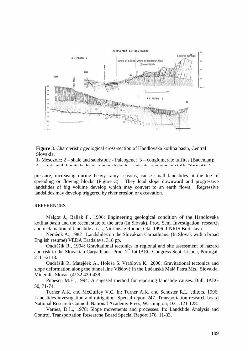
109
pressure, increasing during heavy rainy seasons, cause small landslides at the toe ofspreading or flowing blocks (Figure 3). They load slope downward and progressivelandslides of big volume develop which may convert to an earth flows. Regressivelandslides may develop triggered by river erosion or excavation.
REFERENCES
Malgot J., Baliak F., 1996: Engineering geological condition of the Handlovskakotlina basin and the recent state of the area (In Slovak). Proc. Sem. Investigation, researchand reclamation of landslide areas, Nitrianske Rudno, Okt. 1996. IINRIS Bratislava.
Nemèok A., 1982 : Landslides on the Slovakian Carpathians. (In Slovak with a broadEnglish resume) VEDA Bratislava, 318 pp.
Ondrášik R., 1994: Gravitational tectonics in regional and site assessment of hazardand risk in the Slovakian Carpathians. Proc. 7th Int.IAEG Congress Sept. Lisboa, Portugal,2111-2118.
Ondrášik R. Matejèek A., Holeša S. Vrablova K., 2000: Gravitational tectonics andslope deformation along the tunnel line Višòové in the Lúèanská Malá Fatra Mts., Slovakia.Mineralia Slovaca,4/ 32 429-438.,
Popescu M.E., 1994: A sugesed method for reporting landslide causes. Bull. IAEG50, 71-74.
Turner A.K. and McGuffey V.C. In: Turner A.K. and Schuster R.L. editors, 1996:Landslides investigation and mitigation. Special report 247. Transportation research boardNational Research Council. National Academy Press, Washington, D.C .121-128.
Varnes, D.J.., 1978: Slope movements and processes. In: Landslide Analysis andControl, Transportation Researche Board Special Report 176, 11-33.
Figure 3. Charcteristic geological cross-section of Handlovska kotlina basin, CentralSlovakia.1- Mesozoic; 2 – shale and sandstone - Paleogene; 3 – conglomerate tuffites (Badenian);4 – strata with lignite beds; 5 – upper shale; 6 – andesite, agglomerate tuffs (Sarmat); 7 –

110
PATTERNS OF ACCELERATION FOR LARGE SLOPE FAILURES
David N. Petley5. Department of Geography, University of Durham, Science Laboratories, Durham, DH13LE, UK
In recent years there has been considerable effort expended in the monitoring of themovement of large slope failures. This has tended to concentrate primarily on the use ofground instrumentation, such as inclinometers, and extensometers, for the measurement ofdeformations. In most cases these data have then been correlated with other monitoringdata, such as piezometer readings, and with geotechnical measurements, to understand theconditions that lead to movement. These results have allowed significant advances in theunderstanding of landslide processes to be made, and provided the mechanism by which thestability of a rock mass can be assessed. However, in order for a comprehensive landslidehazard assessment techniques to be developed there is a need to be able to forecast whethera phase of movement in the landslide is likely to lead to a catastrophic failure and, if so,when that failure will occur.
Some considerable progress has been made in this field, but comprehensiveanalyses of the large volume of monitoring data have rarely been undertaken. The mostnotable successes have come in the examination of periods of acceleration of landslides. Ithas been noted that by plotting a graph of the reciprocal of velocity against time (Λ-t), alinear trend is evident prior to failure ( Voight, 1988, 1989; Fukozono 1990). In this case,final failure will occur when Λ=0 (Voight, 1989), and post-event analyses havedemonstrated that this technique could have been used to forecast with a surprising level ofaccuracy the final failure of the Vajont landslide in Italy, an event which led to the deathsof over 2000 people. Recent analyses of large landslide systems have validated these ideas(see Crosta 2001 for example). The linear trend may be attributed to a stress-transferprocess during crack growth (Main et al., 1991) as the basal shear zone forms. There is nowconsiderable evidence that similar effects occur in other large systems in which rockdeformations occur, such as the onset of failure of volcanic flanks (Voight, 1989), theinitiation of volcanic eruptions (Kilburn and Voight, 1998), earthquake initiation (Sornetteand Sornette, 1990), and even the development of rock bursts (Ouillon and Sornette, 2000).
The linear trend in Λ-t space appears to be a powerful tool both for understandingthe development of large failures, and it also provides the potential for the formulation andconstruction of warning systems. However, for this method to be useful it must be able todifferentiate between accelerating phases of movement that do not lead to failure and thosethat do. There is ample evidence that large landslides often undergo periods of enhancedmovement that are not associated with catastrophic collapse prior to the final failure. Forexample, the Vajont failure of 1963 was preceded by two phases of quite rapid movement,one in 1960 and the other in 1962. In both cases the accelerations were triggered byincreases in groundwater level associated with the filling of the reservoir, but in both casesmovement was effectively terminated by subsequent reductions in the lake level. Similarphases of increased movement rate, with later decelerations, have been noted for otherlandslides prior to a final acceleration that leads to catastrophic failure (Petley and Allison1997). Unfortunately, there have been few analyses to determine whether these periods ofacceleration have a different signature in Λ-t space that would allow a differentiationbetween the movement types.
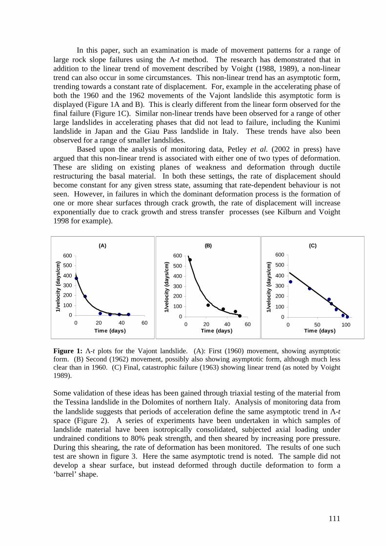
111
In this paper, such an examination is made of movement patterns for a range oflarge rock slope failures using the Λ-t method. The research has demonstrated that inaddition to the linear trend of movement described by Voight (1988, 1989), a non-lineartrend can also occur in some circumstances. This non-linear trend has an asymptotic form,trending towards a constant rate of displacement. For, example in the accelerating phase ofboth the 1960 and the 1962 movements of the Vajont landslide this asymptotic form isdisplayed (Figure 1A and B). This is clearly different from the linear form observed for thefinal failure (Figure 1C). Similar non-linear trends have been observed for a range of otherlarge landslides in accelerating phases that did not lead to failure, including the Kunimilandslide in Japan and the Giau Pass landslide in Italy. These trends have also beenobserved for a range of smaller landslides.
Based upon the analysis of monitoring data, Petley et al. (2002 in press) haveargued that this non-linear trend is associated with either one of two types of deformation.These are sliding on existing planes of weakness and deformation through ductilerestructuring the basal material. In both these settings, the rate of displacement shouldbecome constant for any given stress state, assuming that rate-dependent behaviour is notseen. However, in failures in which the dominant deformation process is the formation ofone or more shear surfaces through crack growth, the rate of displacement will increaseexponentially due to crack growth and stress transfer processes (see Kilburn and Voight1998 for example).
Figure 1: Λ-t plots for the Vajont landslide. (A): First (1960) movement, showing asymptoticform. (B) Second (1962) movement, possibly also showing asymptotic form, although much lessclear than in 1960. (C) Final, catastrophic failure (1963) showing linear trend (as noted by Voight1989).
Some validation of these ideas has been gained through triaxial testing of the material fromthe Tessina landslide in the Dolomites of northern Italy. Analysis of monitoring data fromthe landslide suggests that periods of acceleration define the same asymptotic trend in Λ-tspace (Figure 2). A series of experiments have been undertaken in which samples oflandslide material have been isotropically consolidated, subjected axial loading underundrained conditions to 80% peak strength, and then sheared by increasing pore pressure.During this shearing, the rate of deformation has been monitored. The results of one suchtest are shown in figure 3. Here the same asymptotic trend is noted. The sample did notdevelop a shear surface, but instead deformed through ductile deformation to form a‘barrel’ shape.
(A)
0
100
200
300
400
500
600
0 20 40 60
Time (days)
1/ve
loci
ty (
day
s/cm
)
(B)
0
100
200
300
400
500
600
0 20 40 60Time (days)
1/ve
loci
ty (
day
s/cm
)
(C)
0
100
200
300
400
500
600
0 50 100Time (days)
1/ve
loci
ty (
day
s/cm
)

112
Figure 2: Λ-t plot for the Tessina landslide. Figure 3: Λ-t plot for the Tessina landslide experimental data.
It is proposed that an understanding of this behaviour provides a mechanism for theunderstanding of landslide processes and will potentially allow the development ofmonitoring and warning systems that provide better warnings of possible catastrophicfailures.
REFERENCES
Angeli, M-G., Gasparetto, P., Pasuto, A., and Silvano, S., 1989, Examples oflandslide instrumentation (Italy): Proceedings of the 12th International Conference on SoilMechanics and Foundation Engineering (Rio de Janeiro), 3, 1531–1534.
Cooper, M.R., Bromhead, E.N., Petley, D.J., and Grant, D.I., 1998, The Selbornecutting stability experiment: Geotechnique, 48, 83–101.
Fukozono, T., 1990, Recent studies on time prediction of slope failure: LandslideNews, 4, 9–12.
Kilburn, C.R.J., and Voight, B., 1998, Slow rock fracture as a precursor at SoufriereHills volcano, Montserrat: Geophysical Research Letters, 25, 3665–3668.
Main, I.G., Sammonds, P.R., and Meredith, P.G., 1991, Application of a modifiedGriffith criterion to the evolution of fractal damage during compressional rock failure:Geophysical Journal International, 115, 367–380.
Ouillon, G., and Sornette, D. 2000. The concept of ‘critical earthquakes’ applied tomine rockbursts with time-to-failure analysis: Geophysical Journal International, 143, 454–468.
Petley, D.N., Bulmer, M.H. and Murphy, W. 2002 in press. Movement patterns inrotational and translational landslides. Accepted for publication in Geology. Anticipatedpublication date: August 2002.
Petley, D.N. and Allison, R.J., 1997. The mechanics of deep-seated landslides. EarthSurface Processes and Landforms, 22, 747-758.
0
200
400
600
800
1000
1200
1400
1600
1800
2000
0 200 400 600
Time (mins)
1/ve
loci
ty (
min
s/m
m)
0
5
10
15
20
25
30
35
40
45
0 1 2 3 4 5 6 7 8 9 10
Time (days)
1/ve
loci
ty (
day
s/cm
)

113
Salt, G.A., 1985, Aspects of landslide mobility: Proceedings of the 11th InternationalConference on Soil Mechanics and Foundation Engineering, 3, 1167–1172.
Shuzui, H., 2001, Process of slip-surface development and formation of slip-surfaceclay in landslides in Tertiary volcanic rocks, Japan: Engineering Geology, 61, 199–220.
Sornette, A.,, and Sornette, D., 1990, Earthquake rupture as a critical point:Consequences for telluric precursors: Tectonophysics, 179, 327–334.
Voight, B., 1988, A relation to describe rate-dependent material failure: Science, 243,200–203.
Voight, B., 1989, A method for prediction of volcanic eruptions: Nature, 332, 125–130.
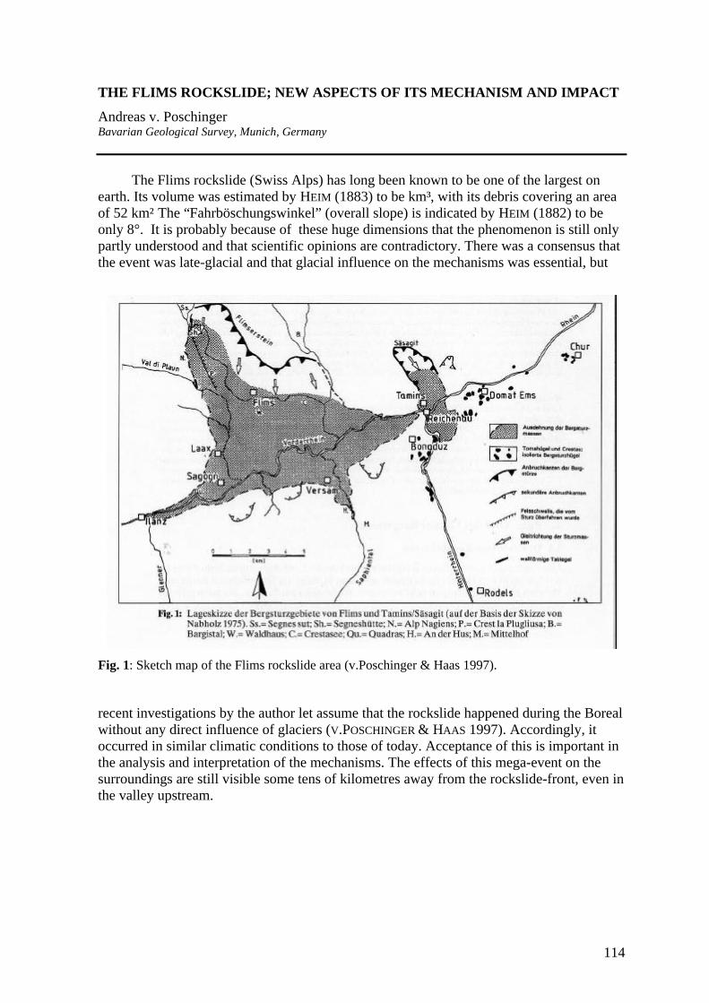
114
THE FLIMS ROCKSLIDE; NEW ASPECTS OF ITS MECHANISM AND IMPACT
Andreas v. PoschingerBavarian Geological Survey, Munich, Germany
The Flims rockslide (Swiss Alps) has long been known to be one of the largest onearth. Its volume was estimated by HEIM (1883) to be km³, with its debris covering an areaof 52 km² The “Fahrböschungswinkel” (overall slope) is indicated by HEIM (1882) to beonly 8°. It is probably because of these huge dimensions that the phenomenon is still onlypartly understood and that scientific opinions are contradictory. There was a consensus thatthe event was late-glacial and that glacial influence on the mechanisms was essential, but
Fig. 1: Sketch map of the Flims rockslide area (v.Poschinger & Haas 1997).
recent investigations by the author let assume that the rockslide happened during the Borealwithout any direct influence of glaciers (V.POSCHINGER & HAAS 1997). Accordingly, itoccurred in similar climatic conditions to those of today. Acceptance of this is important inthe analysis and interpretation of the mechanisms. The effects of this mega-event on thesurroundings are still visible some tens of kilometres away from the rockslide-front, even inthe valley upstream.

115
Fig. 2: The Flimserstein. The rock cliff represents a part of the rear wall of the scar. The village ofFidaz in the middle of the meadows is located on the sliding plane.
According to the present knowledge, the disaster happened in several stages:1. Already before the Flims event another large rockslide (1.0-1.6 km³, ABELE 1974),
called Tamins-Säsagit, blocked the Rhein valley at the junction of Vorder- andHinterrhein and created a large lake (Lake Bonaduz).
2. Long after the retreat of the Würm glaciers, the limestone cliff of Flims collapsedalong bedding planes and released about 8 km³ of rock. Melting of permafrost orsimply stress relaxation might have been involved. High water pressure in the karstsystem within the cliff is assumed to have been a possible trigger.
3. The rock mass displaced the lake water and also the lake-bottom sediments. Thiscreated a water-saturated slurry (PAVONI 1968) that travelled along the former lakeand upstream into the Hinterrhein valley. There they were deposited as unlayered,graded gravel.
4. With the slurry, large masses (50-200 m) of rockslide material were transported faraway from the front of the slide.
5. The Flims rockslide mass blocked the Vorderrhein and created a second lake (LakeIlanz).
6. According to its volume and the mean discharge of the Rhein river, Lake Ilanz isestimated to have been fully impounded in little more than one year andsubsequently overtopped the landslide mass. Thick lake sediments show clearlythat the landslide dam broke after some tens or even hundreds of years. Thisbreach gave rise to a giant debris flow which devastated the Rhein valley. Even inLake Constance (75 km away) a clear anomaly in the sedimentation pattern isvisible and is assumed to be correlated to this event.
In the presentation an outline of the present knowledge about the Flims rockslide will begiven and the implications for the current landslide risk assessment presented.

116
REFERENCES
ABELE, G. (1974): Bergstürze in den Alpen.- Wiss. Alpenvereinshefte, 25, 230 S., München.HEIM, A. (1882): Über Bergstürze.- Neujahrsblatt d. Naturforsch. Ges. Zürich, 31 S. - (1883): Der alte Bergsturz von Flims.- Jb. d. Schweizer Alpenclubs, 18. Jg., S. 295-
309, Bern.
PAVONI, N. (1968): Über die Entstehung der Kiesmassen im Bergsturzgebiet von Bonaduz-Reichenau (Graubünden).- Ecl. Geol. Helv., 61/2, 494-500, Basel.
POSCHINGER, A.v. & HAAS, U. (1997): Der Flimser Bergsturz, doch ein warmzeitlichesEreignis?.- Bull. Angew. Geologie, 2/1, 35-46, Zürich.

117
ASSESSING MASSIVE FLANK COLLAPSE AT VOLCANO EDIFICES USING3-D SLOPE STABILITY ANALYSIS
Mark E. Reid and Dianne L. Brien
U.S. Geological Survey, 345 Middlefield Road, MS 910, Menlo Park, CA 94025 USAtel: (650) 329-4891; FAX: (650) 329-5203; e-mail: [email protected]
Massive (> 0.1 km3) flank collapses have dramatically modified more than 200stratovolcanoes worldwide (Siebert, 1984; Siebert et al., 1987) and pose one of the mostsudden, destructive, and life-threatening of volcanic events. A noteworthy modern exampleis the enormous failure at Mount St. Helens, USA, in 1980 (Voight et al., 1983). Thesemassive collapses generate rock and debris avalanches that may mobilize into debris flows,thereby creating hazards both on the edifice and in areas far downslope or downstream.Moreover, many of the Earth’s ~700 stratovolcanoes endanger residents of developingnations, so techniques are especially needed for rapid and cost-effective hazardassessments. About 20,000 people have been killed by historical flank collapses (Siebert etal., 1987), and understanding how, why, and where volcano slopes collapse is vital toevaluating long-term volcano evolution and immediate hazards.
Numerous processes can destabilize an edifice (Voight and Elsworth, 1997),including volcano-specific effects such as magma intrusion, hydrothermal alteration, andthermal pressurization of pore fluids, as well as more commonly recognized destabilizingeffects such as elevated pore-fluid pressures or earthquake shaking. Although thisabundance of contributing factors complicates collapse predictions, gravity always affectscollapse. The gravitational stability of volcano edifices is strongly influenced by theinterplay between topography, three-dimensional (3-D) potential failure surfaces, and the 3-D distributions of rock strength and pore-fluid pressure. We have created a 3-D slopestability analysis that can extensively search the rockmass underlying a digital elevationmodel (DEM) to determine the locations of minimum stability and the expected volumes ofpotential failure (Reid et al., 2000). Two stratovolcano edifices in the USA, Mount St.Helens and Mount Rainier, have had repeated flank collapses and provide goodopportunities to test the method. In addition, the large failure at Casita volcano, Nicaragua,that was triggered during Hurricane Mitch in 1998, allows us to examine the utility ofreconnaissance stability assessments. Here, we briefly describe the method and presentresults from stability analyses of Mount St. Helens, Mount Rainier, and Casita volcanoes.
A wide variety of slope failures occur on volcano edifices, ranging from smallrockfalls to massive collapses. Most large stratovolcano flank collapses extend deep intotheir edifices, producing volumes between 0.1 and 20 km
3 (Siebert et al., 1987). Initial
sliding for historical large collapses at Mount St. Helens, Bandai (Japan), and Bezymianny(Russia) volcanoes occurred along deep, arcuate failure surfaces (Voight and Elsworth,1997). Rock failure may be arcuate if discontinuities are closely spaced (Hoek and Bray,1981); relatively small discontinuities commonly do not influence the shape of largefailures. A spherical potential failure surface represents the simplest 3-D geometryunconstrained by internal structures or discontinuities. Here, we assume arcuate failuresurfaces consisting of the part of a sphere underlying the topography.

118
We use a 3-D "method of columns" limit-equilibrium slope stability analysis todetermine the stability of all parts of a landscape by computing the stability of manypotential failures. These potential failures include a wide variety of depths and volumesthroughout the materials underlying a DEM (Reid et al., 2000). The method uses a 3-Dextension of the 2-D Bishop's simplified limit-equilibrium analysis for rotational failure(Bishop, 1955), and it can incorporate variable 3-D material properties, 3-D pore-fluidpressure distributions, and simplistic earthquake shaking effects. 3-D stability methodshave been presented elsewhere (Hungr, 1987; Hungr et al., 1989) and 2-D stability methodshave been used to search DEMs for unstable slopes (Miller, 1995); our analyses combinethese ideas. We systematically search the DEM using a 3-D orthogonal search grid ofpoints located above the DEM. Each point in this search grid represents the center ofrotation of a set of spherical trial failure surfaces with different radii. For large flankcollapses, we examine millions of potential failures having volumes between 0.1 and 3.5km3. By aggregating the results, we can create maps portraying stability for all regions ofan edifice, as well as provide estimates of potential failure volumes.
The well documented, catastrophic debris avalanche at Mount St. Helens provides anopportunity to test the 3-D stability analysis. In March 1980, the north flank of St. Helensbegan moving northward at a rate of several meters per day, creating a conspicuous bulgeabout 1.5 by 2 km in area, apparently in response to shallow magma intrusion. Finally onMay 18, the north flank failed rapidly and retrogressively in a series of large blocks (Voightet al., 1983). Using a pre-deformation DEM underlain by dry, homogeneous rocks, ourmethod identified the northwest flank as the least-stable region, although north flankstability was within 5% of the minimum. In this case, topography alone was a reasonable,although inexact, predictor of instability. Using estimates of the conditions that existed twodays prior to collapse, including deformed topography with a north flank bulge andcombined pore-pressure and earthquake shaking effects, we obtained good estimates of theactual initial failure block location and volume (Reid et al., 2000). We also used thismethod to examine potential retrogression of failure into the edifice. For this, weconsidered undrained unloading resulting from the sudden removal of the rock mass duringcollapse. This scenario promoted some retrogression of failure into the edifice, althoughless than that observed during the 1980 event.
At Mount Rainier, more than 55 large collapses in the Holocene have generated far-traveled debris flows (Crandell, 1971); future flows would threaten parts of the PugetSound region that are now densely populated. At Rainier, our analysis using homogeneousrocks predicted a least-stable region in the steep Willis Wall, a region where few largelandslides have originated (Reid et al., 2001). In contrast to St. Helens, Rainier has largeareas of hydrothermal alteration that contain weak rocks. The shear strength of edificerocks varies depending on the degree of acid sulfate-argillic alteration (Watters et al.,2000). In addition, the ability of low-strength, clay-rich rocks to retain pore water duringcollapse enhances their rapid transformation into mobile debris flows (Iverson et al., 1997),which greatly extends their destructive reach. We derived a well-constrained estimate ofthe extent of3-D alteration, and thereby strength, by combining detailed surface geologicmapping (Sisson et al., 2001) with subsurface geophysical imaging (Finn et al., 2001).High-resolution airborne magnetic measurements (Finn et al., 2001) can reveal thesubsurface distribution of alteration because alteration substantially reduces the strongmagnetization of fresh volcanic rocks. Using this 3-D distribution, our analysis predictedthat the least-stable part of the volcano is its upper west flank, in the basin of SunsetAmphitheater, a result consistent with Holocene debris-flow history. Overall, our analyses

119
revealed that sizeable flank collapse (> 0.1 km3) is promoted by voluminous, weak,hydrothermally altered rock situated high on steep slopes (Reid et al., 2001). At thisvolcano, incorporating variable 3-D shear strength was essential to provide a reasonableindicator of instability.
At many other stratovolcanoes there is a pressing need for slope stability evaluations,but time and costs preclude developing the comprehensive geologic information availablefor Mount Rainier. For example, at Casita volcano in Nicaragua a large landslide wastriggered by torrential rainfall from Hurricane Mitch in 1998. This 1.6x10⁶ m3 failuretransformed into a mobile debris flow that completely destroyed two villages (Kerle andvan Wyk de Vries, 2001). Following this event, we investigated the utility of using ourmethod for reconnaissance stability assessments. Although the Casita edifice lacks detailedgeologic mapping, areas near modern fumerolic activity are likely to be hydrothermallyaltered and may include rocks with significantly reduced strengths. By combining adistribution of weaker rocks based on mapped fumerolic areas with a pre-failure DEM andpotential landslide volumes between 0.5 x10⁶ and 5.0x10⁶ m3, we analyzed the pre-Hurricane Mitch stability of the edifice. The source scar for the large failure triggered byHurricane Mitch is located on the southeast flank, an area our analysis predicted asrelatively unstable. In addition, many of the smaller failures that occurred during HurricaneMitch are located in other areas predicted to be relatively unstable. At Casita,reconnaissance stability analysis was able to provide a good indication of impendingunstable areas.
Our 3-D slope stability methods are able to predict reasonable locations and volumesof massive gravitational failures at a variety of stratovolcano edifices. For the relativelyuniform Mount St. Helens edifice, topography alone is a good predictor of the enormous1980 collapse. For volcanoes like Mount Rainier, with large regions of both relativelystrong and weak rocks, collapse hazards vary substantially from sector to sector dependingon the distribution and intensity of alteration and the local relief. Our results from Casitaindicate that even reconnaissance 3-D slope stability analysis may be useful. Thesesuccesses suggest that these methods can be used to assess the potential for massive arcuaterock failures at other volcanoes and mountain massifs.
REFERENCES
Bishop, A.W., 1955, The use of slip circles in the stability analysis of slopes:Geotechnique, v. 5, p. 7-17.
Crandell, D.R., 1971, Postglacial lahars from Mount Rainier Volcano, Washington, U.S.Geological Survey Professional Paper 677, 73 p.
Finn, C.A., Sisson, T.W., and Deszcz-Pan, M., 2001, Aerogeophysical measurements ofcollapse-prone hydrothermally altered zones at Mount Rainier volcano: Nature, v.409, p. 600-603.
Hoek, E., and Bray, J.W., 1981, Rock slope engineering: London, Institute of Mining andMetallurgy, 358 p.
Hungr, O., 1987, An extension of Bishop's simplified method of slope stability analysis tothree dimensions: Geotechnique, v. 37, p. 113-117.
Hungr, O., Salgado, F.M., and Byrne, P.M., 1989, Evaluation of a three-dimensionalmethod of slope stability analysis: Canadian Geotechnical Journal, v. 26, p. 679-686.

120
Iverson, R.M., Reid, M.E., and LaHusen, R.G., 1997, Debris-flow mobilization fromlandslides: Annual Review of Earth and Planetary Sciences, v. 25, p. 85-138.
Kerle, N., and van Wyk de Vries, B., 2001, The 1998 debris avalanche at Casita Volcano,Nicaragua - investigation of structural deformation as the cause of slope instabilityusing remote sensing: Journal of Volcanology and Geothermal Research, v. 105, p.49-63.
Miller, D.J., 1995, Coupling GIS with physical models to assess deep-seated landslidehazards: Environmental and Engineering Geoscience, v. 1, p. 263-276.
Reid, M.E., Christian, S.B., and Brien, D.L., 2000, Gravitational stability of three-dimensional stratovolcano edifices: Journal of Geophysical Research, v. 105, p.6043-6056.
Reid, M.E., Sisson, T.W., and Brien, D.L., 2001, Volcano collapse promoted byhydrothermal alteration and edifice shape, Mount Rainier, Washington: Geology, v.29, p. 779-782.
Siebert, L., 1984, Large volcanic debris avalanches: characteristics of source areas,deposits, and associated eruptions: Journal of Volcanology and GeothermalResearch, v. 22, p. 163-197.
Siebert, L., Glicken, H., and Ui, T., 1987, Volcanic hazards from Bezymianny- and Bandai-type eruptions: Bulletin of Volcanology, v. 49, p. 435-459.
Sisson, T.W., Vallance, J.W., and Pringle, P.T., 2001, Progress made in understandingMount Rainier's hazards: Eos Transactions of the American Geophysical Union, v.82, p. 113-120.
Voight, B., and Elsworth, D., 1997, Failure of volcano slopes: Geotechnique, v. 47, p. 1-31.Voight, B., Janda, R.J., Glicken, H., and Douglass, P.M., 1983, Nature and mechanics of
the Mount St. Helens rockslide-avalanche of 18 May 1980: Geotechnique, v. 33, p.243-273.
Watters, R.J., Zimbelman, D.R., Bowman, S.D., and Crowley, J.K., 2000, Rock massstrength assessment and significance to edifice stability, Mount Rainier and MountHood, Cascade Range Volcanoes: Pure and Applied Geophysics, v. 157, p. 957-976.

PREHISTORIC ROCK AVALANCHES, MOUNTAIN SLOPE DEFORMATIONSAND HAZARD CONDITIONS IN THE MAIELLA MASSIF (CENTRAL ITALY)
Gabriele Scarascia [email protected] di Scienze della Terra, Università degli Studi di Roma “La Sapienza”, ItaliaGianluca Bianchi Fasani, Carlo [email protected]; [email protected] di Ricerca c/o Dipartimento di Scienze della Terra, Università degli Studi di Roma” La Sapienza”,ItaliaStephen G. [email protected] Survey of Canada, Ottawa (ON), Canada
INTRODUCTIONIn the Central Apennines large-scale slope deformations significantly involve mountain
areas where Mesozoic and Neogene limestone ridges are present. Although no historicevent of catastrophic rock slope failure was ever recorded, deposits ascribed to rockavalanche have been observed in this part of the Apennine chain (CINTI et al., 2001) as amarker of the recent and intense geodynamic evolution of the area which is pointed out bysignificant seismicityassociated with mountain beltuplift and consequent erosionprocesses. In this paper, theprehistoric Lettopalena rockavalanche occurred along theSE slope of the Maiella Mt.(PAOLUCCI et al., 2001) andeven older adjacent block-sized chaotic deposit arediscussed within theframework of the slopedeformation processes whosesignatures are recorded bothon a large scale (whole slope) and a local one. In particular, insights into i) lithological andstructural setting as conditioning factors of slope failure mechanisms, ii) geologicalinfluences on early stage post-failure behaviour of the involved rock mass, iii) geomorphiccontrols on rock avalanche mobility and shape of the deposit, are evaluated also in the lightof further potential massive rock slope failures.As a matter of fact, many reported rock avalanches repeatedly involved same slopes andmountain sections or surrounding areas as single events of long-term evolution processes -e.g. Vaiont (SEMENZA & GHIROTTI, 2000), Huascaran (PLAFKER & ERICKSEN, 1978),Argentinan Andes (HERMANNS & STRECKER, 1999).
In this context, the paper is intended to give contributions on hazard assessment inthe area, also through the reconstruction of the temporal pattern of the recorded events.This assumes a fundamental importance because of the presence of several elements at risklocated at the footslope, such as historical villages (e.g. Palena, Lama dei Peligni, Fara SanMartino), an important national road and world famous “pasta” factories.
Fig. 1: Geological sketch of the central-eastern Apennines
121

GEOLOGICAL, GEOMORPHOLOGICAL AND SEISMIC BACKGROUND
The Apennine chain is a Neogene fold and thrust belt whose major thrust systems in theCentral section strike NW-SE and dip gently towards SW. Such systems include, from W to E,Simbruini, Velino-Sirente, Marsica, Morrone, Gran Sasso and Maiella thrust sheets. Theexposed sequences mainly consist of 3 to 5 km thick Triassic-Middle Miocene carbonateplatform, slope and ramp facies (CAVINATO et al., 1995).
The kinematic history of thrusting in the Central Apennines is recorded by Miocene-Pliocene synorogenic sediments and progressively involved younger rocks towards the Adriaticforeland. Since Upper Miocene until Lower Pliocene, multiphased deformational events formedNW-SE and NNW-SSE thrust sheets (Simbruini, Velino-Magnola, Sirente, Marsica units). NW-SE and E-W high angle normal fault systems, generally southwest and southdipping, andextensional basins, of generally post-Messinian age, formed across the southwestern part of thethrust belt and are superimposed upon the compressional Neogene structure (CAVINATO & DE
CELLES, 1999).The arcuate shaped Maiella massif represents the most external outcropping thrust sheet
and is featured by a N-S trending antyclinal structure (Fig. 1). Jurassic-Middle Cretaceousrestricted carbonate platform facies pass to Upper Cretaceous-Upper Miocene carbonate rampdeposits (marls and calcareous marls); they are overlain by Messinian evaporitic deposits andfinally (Early Pliocene) by few tens of metres of hypohaline pelites passing to silico-clasticsynorogenic deposits
(CIPOLLARI et al.,1999).The local sequence is represented by Paleocene carbonate platform and ramp deposits
outcrops which are composed of well bedded grainstones 100m thick (Monte AcquavivaFormation). They are overlain by a 200m thick alternance of thinly bedded and heavily jointedgrainstones and mudstones characterised by interlayer gouge material (Santo Spirito Formation).
Upwards, the Lower Miocene Bolognano Formation is characterised by a paraconformitycontact, as shown by a hardground level. This formation is composed of biodetritic limestoneand alternated marl levels, whose thickness is between 50 and 100m. The subsequent LowerMessinian Arenarie di Taranta Formation is featured by interlayering of calcareous sandstones
see fig. 3
Fig. 2: DTM of southern part of the Maiella Mt. and Aventino R. Valley
122

and thinly bedded bituminous clay-marls followed by evaporitic limestone and gypsum referredto the Messinian Gessoso-solfifera Formation, whose maximum thickness is about 100m. TheLower Pliocene clay and sand contain a typical east-dipping conglomerate level (Conglomeratoa Sphaeroidinellopsis seminulina).Along the eastern slope of theMaiella Mt., the contact betweenthe marly-limestone sequence andthe clay-sand deposits marks asharp morphological changeresulting in two completelydifferent landscapes (Figs. 2 and3).
The first one is a 20 to 38°inclined convex huge dip-slopecut by deep, transverse valleys.The second one is characterizedby a hummocky morphology withhillslopes 10-20° dip largelyinvolved in earth/mud-flowsphenomena and by a drainagenetwork with dendritic pattern.
Fig. 3: Oblique aerial view of the SE slope of the Maiella Mt.and Lettopalena rock avalanche
The upper section of the Maiella slope is featured by intense superficial and subsurfacekarst processes as well as old periglacial forms and deposits. The elongated shape ridge has itssummit at elevation 2795m and the valley bottom to the east (Aventino River valley) is at about550m a.s.l. in the area of Lettopalena. Important springs, whose single discharges are in theorder of some m3/s, are located along the Aventino R. valley.
The significant seismicity of the area testifies the ongoing neotectonic activity, asdisplayed by numerous large and medium sized historic earthquakes (CAMASSI andSTUCCHI, 1997) like the MS 7.0 event that struck the Fucino Plain in 1915, the Lama deiPeligni earthquake in 1933 (MS 5.5), and furtherly shown by recent paleoseismologicalinvestigations (GALADINI et al., 1997; MICHETTI et al., 1996). This assumes significantimportance since rock avalanches are frequently triggered by strong earthquakes (KEEFER,1984). In a tectonically active area such as the Central Apennines, mountain slope
see fig. 4
see fig. 5
Fig. 4: Fish-eye frontal view of the Lettopalena landslide scar
123

deformations and related landslide phenomena cluster along normal and/or thrust faultgenerated mountain fronts (BLUMETTI et al., 1993), thus stressing the fundamental influenceof seismic input, besides the structural and lithological controls on massive rock slopefailures.
THE LETTOPALENA ROCK AVALANCHE
Geological controls on failure and post-failure mechanismsThe Lettopalena case-history shows typical rock avalanche features (Hungr et al.,
2001); it involved about 28·106m3 volume of Eocene and Miocene marly-limestones (S.Spirito Formation and Bolognano Formation), which spread onto the Aventino R. valley.
The geomechanical analysis in the detachment and surrounding areas pointed out thepresence of three main discontinuity sets, including the bedding surface (S1: N32°/35°),while the others are respectively oriented N180°/80° (S2) and N250°/85° (S3). The last oneis gently rotated towards 120°/85° close to the left flank of the detachment area due to thepresence of a significant fault trending N135° which constrained the direction ofmovement of the failed mass.
The rock avalanche headscarp is 50-75m high and about 800m long (fig. 4) and at itsbase thinly bedded (10-20cm) marly limestone outcrop. In the central section of theheadscarp, continuously produced debris feed two fans. On the right flank a stepped profileof the rupture surface is clearly observed also as a consequence of a small differencebetween natural slope and bedding plane directions which is as low as 10°. Just upslope ofthe headscarp there is evidence of gravitational processes involving moderate sized blocks(thousands of m3) delimited by tension cracks open up to 3m and 6m deep, but furthersurveys are needed to detect eventual massive slope deformations.
Buckling phenomena recorded (Fig. 5) within the detachment area, throw light uponthe initial failure mechanisms as a local evidence of larger scale deformation processesalong the slope. In addition, the presence of a bench-like flatter section of the slope, wherethe national road passes through the detachment area, gives some indications on the rupturesurface morphology. It can be assumed that following a stress release caused by the toeerosion of the Aventino R., the quasi dip-slope geometry of this section of the Maiella Mt.enhanced significant bulging on a entire slope-scale and in particular buckling mode ofslope failure on a local scale. According to such a geological-evolutive model, three hingebuckling geometrical model and cusp catastrophe model (QIN et al., 2001) for curved slopehave been considered to analyse stability conditions. These have been coupled with anumerical method approach based on a 2D Distinct Element code to allow for intact rockand joint properties of a blocky system. Main aim of the study was to investigate on thepre-failure deformation processes, possible triggering factors and failure mechanisms of theslope. Based on rock mass characterisation and inferred original slope geometry, previousDEM analyses (PAOLUCCI et al., 2001) were focused on the static and dynamic behaviour,both in dry and partially saturated conditions. The results suggested as possible trigger ofthe rock avalanche a mean sized earthquake during a wet climatic period. In addition, thepresence of the bench at the centre of the detachment surface would be consistent with alarge buckling failure mode evolving in a downslope break off of the failed rock mass,probably enhanced by the discontinuity set S3. This would also explain the quasiunmodified geometry in the lower slope section, except for the two lateral corridors(compare Figs. 2 and 4) where drag effects driven by perimetrical important discontinuitieswould have been effective, and the significant fragmentation of the deposit debris.
124

Shape, lithology and dating of the rock avalanche depositThe shape and the dimensions of the Lettopalena avalanche deposit (Tab. 1) suggest a
low mobility and high energy dissipative event due to the geomorphic control of the pre-existing topography, according to NICOLETTI & SORRISO-VALVO (1991). Nevertheless, themeasured run-up is significant when compared with other reported rock avalanches (EVANS
et al., 1994). Interestingly, avalanche debris do not outcrop on the left bank of the AventinoR., downslope of the depletion area. There is only a small terrace-shaped area, 400mdownstream of the NE margin, where a limited avalanche deposit has been observed, thussuggesting an upslope splash-back of the disintegrating mass. Average dimensions of therock avalanche debris indicate intense fragmentation processes. An inverse grading ofavalanche debris can be observed, though many slide back phenomena, induced bysubsequent toe erosion of the river, locally complicate this general trend. The depositmatrix contains up to 10% of fine grained material. However, it must be stressed thatlandslide damming phenomena can be excluded, since no lacustrine/palustrine deposit hasbeen recognised after detailed surveys upstream of the avalanche deposit. The avalanchedeposit has long been exploited for building material and during quarry activities a buriedwood fragment was found in good preservation conditions. After xylological analyses, itwas ascribed to an oak tree and radiocarbon 14C dating yielded an age of 4.8ky BP. Thisdating leads back to a humid-hot summit, which is significantly consistent with theoutcomes of the DEM analysis about the synchronous action of seismic shaking andsignificant water pressure within the rock mass discontinuity net. In addition, soil materialcontaining organic matter was later sampled just at the contact between the avalanchedebris and the clay substratum at the northern tip of the deposition area. The dating resultsare presently being interpreted.
Runout (L) = 2270 mLength (D) = 1550 mElevation difference = 650 mH/L = 0.29Max. planimetric width of accumulation (Wa) = 1950 mPlanimetric width at D/2 (Wm) = 1200 mWm/Wa = 0.62Wm/D = 0.77Wm/L = 0.53Wa/D = 1.26Wa/L = 0.86Planimetric surface of the original rock mass (Sr) = 6.8 105 m2
Planimetric surface of the volume accumulation (Sd) = 8.5 105 m2
Spreading ( = Sd / Sr ) = 1.25Estimated volume of the debris accumulation (Vd) = 35 106 m3
Average thickness of accumulation ( = Vd / Sd ) = 41 mMaximum height of the descent slope (h1) = 610 mMaximum height of the run-up (h2) = 160 mh2/h1 = 0.26
Fig. 5: Buckling phenomenon; theright flank is observable on thebackground
Tab. 1: Morphometry of the Lettopalena rockavalanche, according to Nicoletti & Sorriso-Valvo(1991) and Evans (1989)
125

ONGOING SLOPE DEFORMATION
The morphotectonic setting of the investigated area allows to set the Lettopalena rockavalanche in a large scale gravitational deformation context involving the whole SE Maiellaslope. In fact, the DTM image (Fig. 2) shows some geomorphological signatures whichsuggest ongoing gravitational deformation processes superimposed on tectonicallygenerated elements. Particularly interesting are the double ridge along the ridge summit, thescar upslope and along the Vallone di Izzo close to the right flank of Lettopalena rockavalanche. At the mouth of this deeply cut valley, on the right bank of the Aventino R., arock avalanche deposit was observed as well, which is interpreted as an event older than theLettopalena one, as inferred from geological contacts with recent slope deposits.In this perspective, the Lettopalena rock avalanche could be interpreted as an evolutionarystage of an incremental gravitational creep process (RADBRUCH-HALL, 1978), involving theslope and causing a widespread bulging process along the lower part of the slope. Thisprocess is also responsible for gravitational phenomena at different scales (SAVAGE &VARNES, 1987) currently occurring in the valley bottom, mainly at the contact between theTertiary marly-limestone sequence with the Pliocene clay-sand-conglomerate deposits.Eventually, also the observed flexural buckling can be considered as a superficialexpression of the above mentioned massive bulging phenomenon.
REMARKS
The observed rock avalanche and mountain slope deformation signatures in the SE partof the Maiella point out significant ongoing gravitational processes in a tectonically activearea such as the Central Apennines. In particular, the Maiella SE mountain front repeatedlyunderwent massive rock slope failures in prehistoric time like Lettopalena rock avalanchewhich occurred approximately 4.8ky BP and which was probably triggered by anearthquake whose magnitude is comparable with other seismic events historically andrecently recorded in the area. These results are basic elements in approaching landslidehazard assessment in the area, in view of the number and of the economic and historicalvalue of exposed elements.
REFERENCES
Blumetti, A.M., Dramis, F. & Michetti, A.M., 1993. Fault generated mountain fronts inCentral Apennines (Central Italy); geomorphological features and seismotectonicsimplications. Earth Surf. Proc. and Landforms, 18, 203-223.
Camassi, R. & Stucchi, M., 1997. Catalogo NT4 dei terremoti.Cavinato, G.P. & De Celles, P.G., 1999. Extensional basins in the tectonally bimodal
central Apennines fold-thrust belt, Italy: response to corner flow above a subductingslab in retrograde motion. Geology, 27, 956-959.
Cavinato, G.P., Cosentino, D., Funiciello, R., Parotto, M., Salvini, F. & Tozzi, M., 1995.Constraints and new problems for geodyamical modelling of the Central Italy (CROP11 Civitavecchia-Vasto deep seismic lines). Boll. Geofis. Teor. Appl., 36, (141-144),159-174.
Cinti G., Donati A. & Scarascia Mugnozza G., 2001. La grande frana di Monte Arezzo(Abruzzo). Mem. Soc. Geol. It., 56, 41-50.
126

Cipollari, P., Cosentino, D. & Gliozzi, E., 1999. Extension and compression related basinsin central Italy during the Messinian Lago-Mare event. Tectonophysics, 315, 163-185.
Evans, S.G., 1989. Rock avalanche run-up record. Nature, 340, n°6231, 271.Evans, S.G., Hungr, O., Enegren, E.G., 1994. The Avalanche lake rock avalanche,
Mackenzie Mountains, Northwest Territories, Canada: description, dating, anddynamics. Canadian Geotechnical Journal, 31 (5), 749-768.
Galadini, F., Galli, P. & Giraudi, C., 1997. Geological investigations of Italian earthquakes:new paleoseismological data from the Fucino Plain (Central Italy). Journal ofGeodynamics, 24, 87-103.
Hermanns, R. & Strecker, M.R., 2001. Structural and lithological controls on largeQuaternary rock avalanches (sturzstroms) in arid northwestern Argentina. G.S.A.Bulletin, 111, 934-948.
Hungr, O., Evans, S.J., Bovis, M.J. and Hutchinson, J.N., 2001. A review of theclassification of landslides of the flow type. Environmental and EngineeringGeoscience, Vol. VIII, n° 3, 1-18.
Keefer, D.K., 1984. Landslides caused by earthquakes. G.S.A. Bull., 95, 406-421.Michetti, A.M., Brunamonte, F., Serva, L. & Vittori, E., 1996. Trench investigation of the
1915 Fucino earthquake fault scarps (Abruzzo, Central Italy): geological evidence oflarge historical events. Journal of Geoph. Res., 101, n. B3: 5921-5936.
Nicoletti P.G. & Sorriso Valvo M., 1991. Geomorphic controls of the shape and mobility ofrock avalanches. G.S.A. Bulletin, 103, 1365-1373.
Paolucci, G., Pizzi, R. & Scarascia Mugnozza, G.,2001. Analisi preliminare della frana diLettopalena (Abruzzo). Mem. Soc. Geol. It., 56, 131-137.
Plafker, G. & Ericksen, G.E., 1978. Nevados Huascaran avalanches, Peru, in Voight B., ed.,Rockslides and avalanches, Elsevier: 277-314.
Qin, S., Jiao, J.J. and Wang, S., 2001. A Cusp Catastrophe Model of instability of slip-buckling slope. Rock Mech. Rock Engng., 34 (2), 119-134.
Radbruch-Hall, D.H., 1978. Gravitational creep of rock masses on slopes, in Voight B., ed.,Rockslides and avalanches, Elsevier: 607-653.
Savage, W.Z. & Varnes, D.J., 1987. Mechanics of gravitational spreading of steep-sidedridges (“Sackung”). Bull. of the Int. Ass. of Eng. Geol., 35, 31-36.
Semenza. E. & Ghirotti, M., 2000. History of the 1963 Vaiont slide: the importance ofgeological factors. Bull. Of Eng. Geol. and the Environment, 59, n° 2, 87-96.
127

128
IMPACTS OF LANDSLIDE DAMS ON MOUNTAIN TOPOGRAPHY
Robert L. Schuster, Scientist Emeritus,U.S. Geological Survey, Box 25046, Mail Stop 966, Denver, Colorado 80225, USA
INTRODUCTION
This abstract will discuss the effects of landslide dams on the topography of theEarth’s surface, particularly on the morphologies of mountain valley systems. Landslidedams form in a variety of physiographic settings. However, high landslide dams thatimpound large-volume lakes occur most frequently in narrow steep-walled valleys inmountainous regions because (1) these valleys are particularly subject to slope failure and(2) their narrow cross sections require relatively small amounts of materials to block thestreams (Schuster & Costa 1986, Costa & Schuster 1988, Schuster 1995). Mountain valleysalso provide optimal sites for low landslide dams, commonly formed by debris flowsissuing from tributary valleys.
Landslide dams range in height from only a few meters to hundreds of meters. Theworld’s largest and highest historic landslide dam was formed by the 1911 earthquake-triggered Usoi rock slide–rock avalanche, which dammed the Murgab River in the PamirMountains of southeastern Tajikistan (Gasiev 1984, Alford & Schuster 2000, Schuster2000, Hanisch in press). The resulting 600-m-high dam impounds 53-m-long Lake Sarez,which is approximately 550 m deep. This natural dam is twice as high as 300-m-high NurekDam (also in Tajikistan), the world’s highest man-made dam.
Landslide dams may last for several minutes, for several thousand years, or, in a fewcases, may become geologically “permanent,” i.e., the dam does not fail in the short term,and in the long term the lake will fill with sediment to form a lacustrine plain. Those damsthat fail quickly have little upstream effect on valley morphology; however, downstreameffects of flooding and/or debris flows can be significant. The landslide dams that do notfail remain as long-term geologic features that significantly affect mountain topography.The world’s outstanding example of a still existing, pre-historic landslide-dammed lake isLake Waikaremoana on the North Island of New Zealand. This 250-m-deep lake, with anarea of 56 km2, was formed 2,200 years ago by a 2.2x10⁹m3 rock slide in Tertiarysandstones and siltstones (Read et al. 1992, Riley & Read 1992). The slide formed a 400-m-high blockage of the Waikaretaheke River.
PROCESSES OF TOPOGRAPHIC IMPACT BY LANDSLIDE DAMS
In addition to the direct effects of the landslide on local topography, a landslide damcan have major impacts on topography both upstream and downstream of the dam:
Upstream impacts –• By blocking the stream, the dam forms a knickpoint (knickpunkt) in the stream
profile, thus decreasing the stream gradient upstream.• By its inherent function as a dam, the landslide impounds a lake, which may or may
not be permanent. This lake serves as a basin for deposition of sediment. If the damis geologically “long-term,” the lake will sooner or later fill with sediment andbecome a lacustrine meadow or plain. If a long-term dam fails, it may leave behindlacustrine terraces that are incised by the downcutting stream.
• If the dam fails, secondary landslides may occur along the lake shore due to rapiddrawdown. These landslides remain as long-term topographic features.

129
Downstream impacts –• Downstream from the knickpoint formed by the landslide dam, the stream gradient
will be steeper than originally and steeper than upstream from the dam.• Leopold et al. (1964. p. 454-455) noted that man-made dams trap 95-99 percent of
the sediment that passed before the dams were built. Clear water is released fromthe dam instead of the sediment-laden flows that existed prior to construction. Thecombination of clear water and changing flow regimen leads to erosion of thechannel and lowering or degradation of the bed of the channel downstream from thedam. The same process occurs downstream from long-lived landslide dams.
• If a landslide dam fails catastrophically, downstream deposition of sediment derivedfrom the dam itself and from sediment that has been deposited behind the dam willoccur as outburst debris flows (Schuster 2000). These debris-flow deposits can havelong-term impacts on mountain valley topography.
OUTSTANDING CASE HISTORIES
Worldwide, many of today’s large landslide dams and their lakes have been inexistence for hundreds or even thousands of years, and thus already have had long-termeffects on mountain topography. Especially noteworthy are previously mentionedWaikaremoana landslide dam and lake, New Zealand, and Usoi landslide dam and LakeSarez, Tajikistan. Also worthy of mention is 700-yr-old Slumgullion landslide dam andLake San Cristobal in southwestern Colorado, USA. This natural dam seems to be“permanent” because its natural spillway crosses an erosion-resistant bedrock ledge.Interestingly, during its existence about one-fifth of the length of the lake has filled withsediment; thus, the lake is well on its way to becoming a “mountain meadow” (Schuster1996).
Another example of the deposition of sediment in a landslide-dammed lake has beenprovided by the 1941 Tsao-Ling landslide dam on the Chin-Shui River, central Taiwan,where a 50-m depth of lacustrine sediments deposited in the impoundment caused severesiting problems for a proposed hydroelectric power project (Chang 1984). The gradient ofthe riverbed upstream from the knickpoint at this landslide dam is 1.1 percent, whereasdownstream it is 7.6 percent. The 1941 Tsao-Ling landslide dam failed in 1942. However,another landslide dam was triggered at approximately the same site by the September 1999Chi-Chi earthquake. This natural dam, which impounds a new lake
with a volume of about 46 million m3, has been prevented from failing by installationof lined spillways and check dams (Schuster & Throner 2000). Thus, the dam and lake areintended to be long-term topographic features and to have a lasting effect on the gradient ofthe Chin-Shui River. Similar long-term effects on stream gradient can be noted forsediments deposited behind a prehistoric landslide on the north Fork of the Virgin River inZion National Park, Utah, U.S.A. (Hamilton 1992).
Another example of a large landslide-dammed lake that has become a “permanent”topographic feature because of the interference of man is Spirit Lake in the Cascade Rangeof the State of Washington, USA. Today’s Spirit Lake (volume: 258 million m3) wasimpounded by the 2.8-km3 debris avalanche that was triggered by the May 1980 eruption ofMount St. Helens (Schuster 1989). To prevent overtopping, probable failure of the 60-m-high landslide dam of the North Fork Toutle River, and a catastrophic outburst flood, theU.S. Army Corps of Engineers constructed a 2.6-km-long outlet spillway tunnel throughthe right abutment ridge of the natural dam, thus ensuring that the dam and lake wouldbecome long-term topographic features (Sager & Budai 1989).

130
In the fall of 1983, Thistle Lake (volume: 78 million m3), the impoundment behindthe 63-m-high Thistle landslide dam in central Utah, USA, was permanently drained by atunnel spillway constructed through the bedrock right abutment (Hansen & Morgan 1986).However, the massive landslide dam itself remains as a noteworthy topographic featureacross the Spanish Fork River.
There are many cases of downstream debris-flow deposition resulting fromcatastrophic failure of a landslide dam. One of the most interesting was the July 1963failure of prehistoric Lake Issyk landslide dam in the Tien Shan Range of northeasternKyrgystan. This 55-m-high natural dam provided a natural debris-retention basin for flowsfrom the upper Issyk River. In July 1963, failure of an upstream moraine dam caused aflood of water to enter Lake Issyk, which overtopped and quickly breached the landslidedam. At the time of the lake outburst, about 30 percent of the18-million- m3 volume of thelake consisted of mud/debris that had been deposited in the lake by earlier debris flows. Theresulting catastrophic outburst debris flow left a downstream debris cone 8 km long and asmuch as 2.5 km wide (Litovchenko 1964).
In another example of the impact on downstream valley morphology of deposits fromfailure of a large landslide dam, overtopping of the 210-m-high Bairaman River landslidedam on the island of New Britain, Papua New Guinea, in September 1986, released anoutburst debris flow as much as 100 m deep into the downstream canyon (King et al. 1989).Although the fine materials in this flow were washed into the Solomon Sea, much of thecoarser material remains as terraces along the shores of the Bairaman River.
Downstream deposition also resulted from partial failure in 1992 of a 100-m-highlandslide dam on the Río Toro in Costa Rica, which deposited a depth of 10 m of sedimentat the site of a proposed power plant 700 m downstream from the landslide dam (Mora etal. 1999).
Failure of a landslide dam often causes secondary landsliding along the lake shoredue to rapid drawdown. An example of this phenomenon occurred along the shore of the30-km-long lake that was impounded by the 1974 Mayunmarca landslide dam on the RíoMantaro in eastern Peru (Kojan & Hutchinson 1978). These secondary landslides, whichwere mostly thin debris slides, had only minor effects on the morphology of the MantaroValley, but had major effects on the highway along the lower valley wall.
REFERENCES CITED
Alford, D. and Schuster, R.L. (eds.) 2000. Usoi landslide dam and Lake Sarez – anassessment of hazard and risk in the Pamir Mountains, Tajikistan: United Nations,Geneva, ISDR Prevention Series No. 1, 113 p.
Chang, S.C. 1984. Tsao-Ling landslide and its effect on a reservoir project. In Proc., 4th
Int’l. Symp. on Landslides, Toronto, 16-21 Sept., v.1, p. 469-473.Costa, J.E. & Schuster, R.L. 1988. The formation and failure of natural dams. Geol. Soc.
Am. Bull. v. 100, p. 1054-1068.Gasiev, E. 1984. Study of the Usoy landslide in Pamir. In Proc. 4th Int’l. Symp. on
Landslides, Toronto, v. 1, p. 511-515.Hamilton, W.L. 1992. The sculpturing of Zion—guide to the geology of Zion National Park,
Zion National Hist. Assoc., Zion National Park, Springdale, Utah, 132 p.Hansen, D.C. & Morgan, R.L. 1986. Control of Thistle Lake, Utah. In Schuster, R.L. (ed.)
Landslide dams: processes, risk, and mitigation Am. Soc. Civil Engrs. Geot. Spec. Publ.No. 3, p. 84-96.

131
King, J., Loveday, I., & Schuster, R.L. 1989. The 1985 Bairaman River landslide dam andresulting debris flow, Papua New Guinea: Quart. Jour. of Engrg. Geol., v. 22, no. 4, p.257-270.
Kojan, E. & Hutchinson, J.N. 1978. Mayunmarca rockslide and debris flow. In B. Voight(ed.), Rockslides and avalanches, 1, Natural phenomena, Amsterdam, Elsevier, p. 316-361.
Leopold, L.B., Wolman, M.G., & Miller, J.P. 1964. Fluvial processes in geomorphology,San Francisco, W.H. Freeman & Co., 522 p.
Litovchenko, A, F, 1964, Katstroficheskii selevoi povadok na r. Issyk. Meteorologiia IGidrologiia, v. 4, p. 39-42.
Mora, S., Madrigal, C., Estrada, J., & Schuster, R.L. 1999. The 1992 Rio Toro landslidedam, in K. Sassa (ed.), Landslides of the world, Japan Landslide Soc., Kyoto, KyotoUniv. Press, p. 369-373.
Read, S.A.L., Beetham, R.D. & Riley, P.B. 1992. Lake Waikaremoana barrier – a largelandslide dam in New Zealand. In D.H. Bell (ed.), Landslides, Proc., 6th Int’l. Symp. onLandslides, Christchurch, 10-14 Feb., v. 2, p. 1481-1487.
Riley, P.B. & Read, S.A.L. 1992. Lake Waikaremoana – present day stability of landslidebarrier. In D.H. Bell (ed), Landslides, Proc., 6th Int’l. Symp. on Landslides,Christchurch, 10-14 Feb., v. 2, p. 1249-1255.
Sager, J.W. & Budai, C.M. 1989. In Galster, R.W. (ed.), Engineering geology inWashington, Wash. Div. of Geol. & Earth Resources Bull. 78, v. 2, p. 1229-1234.
Schuster, R.L. 1989. The 1980 eruptions of Mount St. Helens: engineering geology. InGalster, R.W. (ed.), Engineering geology in Washington, Wash. Div. of Geol. & EarthResources Bull. 78, v. 2, p. 1203-1228.
Schuster, R.L. 1995. Landslide dams – a worldwide phenomenon: Jour. Japan landslideSoc., v. 31, no. 4, p. 38-49 (in Japanese).
Schuster, R.L. 1996. Slumgullion landslide dam and its effects on the Lake Fork. Chapt. 6in Varnes, D.J. & Savage, W.Z. (eds.), The Slumgullion earth flow: a large-scale naturallaboratory: U.S. Geol. Survey Bull. 2130, p. 35-42.
Schuster, R.L. 2000. Outburst debris-flows from failure of natural dams, in Wieczorek,G.F. & Naeser, N.D. (eds.), Debris-flow hazards mitigation, Proc., 2nd Int’l. Conf. onDebris-Flow Hazards Mitigation, Taipeh, 16-18 August, p. 29-42.
Schuster, R.L. 2002. Usoi landslide dam, southeastern Tajikistan, in Proc., Int’l. Symp. onLandslide Risk Mitigation and Protection of Cultural and Natural Heritage, Kyoto, 21-25 Jan., p. 489-505.
Schuster, R.L. & Costa, J.E. 1986. A perspective on landslide dams. In R.L. Schuster (ed.),Landslide dams: processes, risk, and mitigation, Am. Soc. Civil Engrs. Geot. Spec.Publ. No. 3, p. 1-20.
Schuster, R.L. & Throner, R.H. 2000 Technical Review of Tsao-Ling landslide mitigationefforts. U.S. Bureau Reclamation report to Gov’t. of Taiwan, Feb. 24, 35 p.

132
DYNAMICS AND MECHANISM OF DEVELOPMENT OF HUGE SEISMOGENICROCKSLIDES AND ASSESSMENT OF THEIR HAZARD WITH REFERENCE TOTHE EXAMPLE OF USOISKY ROCKFAILURE, TAJIKISTAN.
A.I.Sheko
All-Russian Research Institute for Hydrogeology and Engineering Geology (VSEGINGEO), Moscow Region,Russia
Earthquakes in mountainous countries are accompanied by huge rockslides, whichoften dam mountain rivers. Breach of rockslide dams cause floods and mudflows leading tocatastrophic destructions. The paper discusses the Usoisky rockslide (Tajikistan) as anexample demonstrating the dynamics and mechanism of development of huge seismogeniclandslides and assessment of their hazard.
The Usoisky rockslide happened at night between 19 and 20 February 1911 during astrong earthquake. A huge rock massif (2.2 km3) was separated from the right-hand bank ofMurgab River (in the area of the left tributary of Usoy Dara River, Pamir), fell down anddammed the Murgab River valley. Afterwards, upstream from the rockslide two lakes wereoriginated – Sarez and Shadau.
The dimensions of the rockslide dam are: the length from upper to downstream water– 3750 m; maximum width from the scar wall to the valley left bank – 5200 m; total area –10.8 km2; surface area that is not flooded with water – 9.2 km2; maximum absoluteelevation of the surface – 3496.1 m, minimum one – 2963.3 m. The parameters ofSarezskoye Lake are: the length - ∼70 km with a water amount of about 17 km3; absolutemark of water line (by 10 August 1968) - 3267 m3; absolute mark of water discharge in theupper edge of the canyon – 3119 m; maximum depth – ∼ 500 m; maximum exceeding ofthe water-dividing ridge above the water table level – 228.8 m, minimum one – 55 m.
In the periods of 1968-1969 and 1975-1977 at the Usoi rockslide and adjacent areas, agreat amount of geological, engineering-geological, hydrogeological, geodetic andexperimental investigations have been carried out by VSEGINGEO in conjunction with theHydrogeological Expedition of the Geology Department of Tajikistan under the methodicalleadership of the author. In the course of the investigations the dynamics and mechanism ofthe Usoi rockslide was studied and the related adverse consequences were assessed.
Genetically, the Usoi rockslide dam presents a complicated formation where the mainrole belongs to rock-sliding processes.
The following stages can be distinguished in the formation of the blockage: Stage I –the main rockslide movement; Stage II – glacier-like failure; Stage III – mudflows andformation of a canyon.
In turn, deposits formed during each stage are subdivided into zones and the latter –into areas.

133
During stage I have the following zones were formed: (a) foremost rockslide massifs;(b) swells of extrusion and pushing out; (c) zone of intensive compression and backdisplacement.
Of predominance at Stage II were glacial-like landslides. This stage included: thefailure of back rock massifs; formation of a zone of rockfall accumulations; the scaracquired its modern shape.
During stage III, that still continues proceeding at the present time, the followingzones formed: (a) mudflow deposits; (b) zone of karst-suffosion processes; (c) erosioncanyon.
The mechanism of the Usoi rockslide formation can be presented in the followingway.
The right-hand steep slope of the Murgab River valley was in an unstable state due toriver undermining, weakening by tectonic faults and melt glacier water infiltration. Duringa strong seismic shock, a huge rock massif of the Sarezskiy assise was separated along atectonic fault. The movement of the massif was very speedy and with a very high energyrelease, i.e. about 15.6-18.3⋅1014 ergs for 300 m of an average displacement of the slidingmassif center of gravity.
At first, the massif moved towards the south-east. However, after meeting with theopposite bank of the valley, it deflected to the east. The central part of the massif overcamethe watershed between the Murgab River and its left-hand tributary Shadau, composed oftwo socle terraces, and collapsed into the Shadau River valley, having pressed out thebottom of the latter by 350 m high on its right-hand bank.
When the foremost rock swell set itself against the Murgab valley right-hand bank,under the repulse action of the latter the back part of the massif was separated and beganmoving to the opposite direction.
At the second Stage the rocks collapsed into the proximal depression, and formed aglacier-like avalanche.
At Stage III the blockage formation was connected with the action of mudflows, inwhich the aqueous component was formed due to glacier melting and solid one – tomoraine. At first, mudflows moved in the south-western direction along the scar wall. Themudflows and water seepage through the rockslide body were the main reasons forwashing-out of the latter in its back part, composed of easily erosible sediments of glacier-like landslides.
The first appearance of water through the dam was observed in 1914. The canyon wasgrowing very irregularly. During the first ten years the velocity of the canyon head wasfrom 900 m (1914-1915) to 100 m (1915-1926) per year. During 42 years (1914-1956) thelength of the canyon head movement reached 2.4 km. The comparison of the aero-photosof 1947 and 1966 showed that during these 20 years the canyon head actually did notmove. This can be explained by that after the Usoi-Dara Stream was dammed, themudflows changed their direction and began discharging not to the canyon, but to the SarezLake.

134
At the present time the Usoi blockage body has the following processes underdevelopment: water seepage from the Sarez Lake, mudflows, karst-suffosion processes andlandslides.
The water seeps from the Sarez Lake through the dam in the form of individualspurts.
The real water velocities in different directions vary from 1.5 to 4.5 m/sec. The SarezLake discharges the water into the canyon, formed in landslide deposits. The half of thedischarged water enters through the springs in the canyon left-hand bank, whereas thesecond half – through its bottom.
The water discharges vary from 40 to 90 m3/sec depending on a season. They arehigher in summer, than in winter. The water seepage from the Sarez Lake was firstobserved in 1914 when the water level in it was 175 m lower than the present-day one.
The water permeability of the dam decreases with depth. At a depth of over 150 m theblockage is composed of monolithic rockslide blocks that are actually water-proof. Thepermeability at a depth of 50 m is only 20-30 m3/sec.
The mudflows are observed in the northern part. They are discharged to the SarezLake and do not influence the blockage stability.
The sliding and karst-suffosion processes also cannon be a reason for dam`sdestruction.
The major part of the Usoi rockslide is composed of low-disturbed rockslide massifsand presents a stable structure. Of a hazard is the right-hand bank of the valley upstreamfrom the dam where there is a probability of collapsing huge (up to 2 km3) rock masses intothe Sarez Lake, due to which the water can flow over the dam and wash loose material at itslower northern part out to a depth of 50-70 m. The expected failure can take place alongthree (tectonic?) fissures that are 3 km long at an elevation of about 4000 m. Also, smalllandslides can occur on the left-hand bank, directly near the Usoi blockage.
The modeling has shown that the water overflow is possible through the lowerednorthern part of the dam composed of destructed rocks. However, it was not managed todetermine reliably the water amount which could overflow. Based on the analysis of theVaiont catastrophe, it can be supposed that the water amount, which will be thrown outfrom the Sarez Lake, will be several times higher. This will cause catastrophic destructionin the valleys of the Pyandj and Amu-Daria Rivers. The water wave can reach the Aral Sea.Millions of people can turn out to be in the zone of disaster.

135
NUMERICAL MODELLING OF ROCK SLOPES USING A TOTAL SLOPEFAILURE APPROACH
Doug SteadDepartment of Earth Sciences, Simon Fraser University, 8888 University Drive, Burnaby, V5A 1S6, Canada.e-mail: [email protected] .
John CogganCamborne School of Mines, University of Exeter, Redruth, Cornwall, TR15 1SE, UK.e-mail: [email protected] .
INTRODUCTION
Numerical modelling of rock slope failures has traditionally involved an emphasis oneither the initiation or transport and depositional characteristics. Both continuum models,FLAC (Itasca 2002), Visage, (VIPS, 2001) and discontinuum models, UDEC (Itasca 2002)have been used increasingly in recent years to simulate the initiation of a rock slope failure. Arange of constitutive models and methods have been applied with varying success. Coggan etal. (1998) describe current methods used in rock slope analysis emphasising both the choice ofappropriate models and good modelling practice. Recent developments have seen continuumcodes developed which are specifically directed toward slope modelling, FLAC/Slope, (Itasca2002). A major question that rock slope engineers will always need to answer is the risk posedby the rock slope failure; this requires an estimate of the spatial risk; something that is notreadily available from routinely used numerical models. To date most analyses addressing theissue of spatial risk have involved analytical models based on rheological and frictional flow.These models allow an estimate of both the run-out distance and velocity of the slope failureand after calibration against field constraints have been shown to be of significant practicalapplication. (Hungr 1995); they however deal principally with the transport and depositionalaspects of the failures. Couture et al (1996) discussed the varied zones in a rock slope failureincluding the initiation/detachment zone, the transport zone and the zone of deposition.Attempts have been made to investigate the rock relationship of rock failure debris with thepre-existing rock mass structure using Stereoblock.
The relatively recent introduction in rock engineering of particle flow codes responds toa need to simulate the complete failure process both in underground and surface environments.Calvetti et al. (2000) show the potential for using the particle flow code PFC2D in thesimulation of debris flow movements. In this method the failure mass is simulated using anarrangement of circular (2D) or spherical (3D) particles. These particles may be bondedtogether to form joint-bound blocks. The development of instability in the slope results ininduced stresses that break the bonds between the rock blocks. In this way the initiation,fragmentation and flow of the failure debris can be simulated. The current paper presents analternative technique for simulating the “total rock slope failure process” using a combinedfinite element-discrete element code, ELFEN, (ELFEN, 2002).

136
Figure 1.The use of combined the finite-discrete element,ELFEN, to simulate rock blasting, after Munjiza et al.(1995)
THE COMBINED FINITE-DISCRETE ELEMENT MODEL
The combined finite–discrete element method, with fracture propagation, has been usedsuccessfully in rock engineering to simulate processes of rock bursting in deep undergroundmines, mining of tabular orebodies, and the blasting of rock slopes in open pit mining. Munjizaet al. (1995) illustrated the use of a finite element mesh to represent the rock slope to beblasted, Figure 1. The effect of the detonation of successive blast holes is simulated by theprogressive growth of fractures in the rock mass resulting in the formation of discrete elements.These deformable discrete elements are re-meshed and the analysis continued. The gradualbreakdown of the rock mass in response to the blast results from fracture growth; re-meshingand the formation of smaller discrete elements. The ELFEN code thus allowed the efficiency ofthe blast to be increased and in addition a comparison between the simulated and the observedblast muck pile size distribution.
The combined finite element-discrete element code with fracture has also been used toinvestigate comminution during thegrinding of materials in rock crushers. TheELFEN code in addition possesses a2D/3D particle flow code module to allowsimulation of the frictional flow ofcircular/spherical particles.
The current researchers saw obviousparallels between the simulations of theprocesses involved in blast throw, rock pilemovement, comminution/flow and thoseactive in the “total rock slope failureprocess”. This paper provides a briefdescription of the combined finite-discreteelement code and preliminary results in itsuse to simulate varied rock slope failuremechanisms. It should be emphasised thatthe authors recognise that, as with any newmethod, a thorough and extensive processof back-analysis against major rock slopefailure with available field/laboratory datais required. The prime purpose of thispaper is to demonstrate the significantpotential of this technique, recognising intheir ongoing research the need toprovide more constraint through the
integrated use of alternative modelling methods and site observations.
The combined finite-discrete element code utilises a variety of constitutive criteriaincluding linear elastic (isotropic/orthotropic), non-linear (Mohr Coulomb, Druker-Prager, VonMises, Rankine etc), Visco-plastic and rigid. The tensile failure and crack propagation ismodelled using a post initial yield rotating crack or Rankine formulation. Anisotropic damageevolution is simulated by degrading the elastic modulus in the direction of the major principal

137
Figure 2.The use of combined the finite-discrete element, ELFEN, to simulate the Randa Rockslide,Switzerland, 1991.
stress invariant. The damage parameter, w, is dependent on the fracture energy, Gf which isrelated to the critical stress intensity factor, KIC by Gf = K2
IC/E. At some point in the analysis ofa rock slope the adopted constitutive model predicts the formation of a failure band within asingle element. The load carrying capacity across such localised bands decreases to zero asdamage increases until eventually the energy needed to form a discrete fracture is released. Atthis point the topology of the mesh is updated, initially leading to fracture propagation within acontinuum and eventually resulting in the formation of discrete elements as the rock fragments.(ELFEN, 2002). Efficient algorithms have been developed for contact searching however it isapparent that the continuous production of new smaller and smaller discrete elements for largeproblems may require considerable computing power, particularly for three dimensionalproblems. In response to this facilities exist for a parallel computing approach.
PRELIMINARY APPLICATIONS OF THE COMBINED FINITE ELEMENT-DISCRETEELEMENT CODE. ELFEN
Case 1. The Randa Rockfall.
The authors have undertaken a preliminary modelling exercise of the Randa Rockslide,Switzerland which occurred in April/May 1991. This model complemented Continuum andDiscontinuum models and is presented in Eberhardt et al (2001). Figure 2 shows a series ofsnapshots of the failure process which occurred in two stages, a lower rockslide and a laterupper rockslide. Further details of this model will be presented in the full paper.
Please Wait..
Please Wait..
Please Wait..
Please Wait.. Please Wait.. Please Wait..

138
Case 2. Biplanar Failure
Biplanar rock slope failures are a common feature in many UK opencast coal mines. Thesefailures frequently comprise a rear failure surface long a fault and a lower basal failure along aplane of weakness, such as a seatearth. For such failure to occur a kinematic space constraint isassumed to require the formation of an interwedge interface. A graben feature often developesin the post failure topography. Figure3 illustrates a preliminary model of such a biplanar failuregeometry and clearly shows the brittle internal fracturing that accompanies rock slope failure.
Case 3. The Delabole Slate Quarry Rock Slope Failure.
Distinct Element modelling of a rock slope failure at Delabole Slate quarry rock of hasbeen previously undertaken using the UDEC discontinuum code, Coggan and Pine (1996).Further details of the slope failure will be provided in the full paper. Figure 4 shows apreliminary plot of an ELFEN simulation of the Delabole rock slope failure.
Figure 3. Preliminary model of biplanar rock Figure 4. Preliminary model of rock slope slope failure in slate quarry
Further preliminary examples of the application of combined finite –discrete elementmodelling will be presented in the full paper and presentation. These will include both variedfailure mechanisms and major European/North American rock slides
CONCLUSIONS
The authors believe that combined finite–discrete element modelling with brittle fracturegeneration will form a major advance in rock slope analysis. Future work is required to applythis method to varied rock slope failure back-analyses in order to constrain input data andimprove our understanding of rock slope failure mechanisms.
Please Wait.. Please Wait..
Please Wait.. Please Wait..

139
REFERENCES
Calvetti, F., Crosta, G. and Tatarella,M. 2000. Numerical simulation of dry granular flows:form the reproduction of small scale experiments to the prediction of rock avalanches.Rivista Italiana di Geotecnica 2/2000. p21-38.
Couture, R., Evans, S.G., Locat, J., Hadjigeorgiou and Antoine, P. 1999. A proposedmethodology for rock avalanche analysis. Slope Stability Engineering. Eds. Yagi,Yamagami and Jiang. P1369-1378.
Coggan, J. S., and R. J. Pine. 1996. Application of Distinct-Element Modelling to Assess SlopeStability at Delabole Slate Quarry, Cornwall, England," Trans. Instn. Min. Metall., Sec. A,105, A22-A30 (January-April 1996).
Coggan, J.S., Stead, D. & Eyre, J.M. (1998). Evaluation of techniques for quarry slope stabilityassessment. Transactions of the Institution of Mining and Metallurgy - Section B 107:B139-B147.
Eberhardt, E., Stead, D., Coggan, J. & Willenberg, H. (2002). An integrated numerical analysisapproach to the Randa rockslide. In Rybár et al. (eds.), Landslides in the Central Europe,Proceedings of the 1st European Conference on Landslides, Prague. Swets & Zeitinger,The Netherlands (In Press).
ELFEN. 2001. Elfen User Manual Version 3.04. Rockfield Software Limited, Swansea, UK.Hungr, O. (1995). A model for the runout analysis of rapid flow slides, debris flows, and
avalanches. Canadian Geotechnical Journal. 32:610-23.Itasca 2002. FLAC/Slope. User’s Guide. A mini-version of FLAC to calculate factor of safetyof slopes,. 74pp, Itasca Consulting Group, Inc. Minneapolis.Itasca 2002. FLAC 4.0. User’s Guide. Itasca Consulting Group, Inc. MinneapolisItasca 2002. UDEC Version 3.1. Universal Distinct Element Code. Itasca Consulting Group,Inc. Minneapolis.Munjiza, A., Owen, D.R.J. and Bicanic, N. 1995. A combined finite-discrete element methodin transient dynamics of fracturing solids. Engineering Computations. 12:145-174.VIPS 2001. Visage – Vectorial Implementation of Structural analysis and Geotechnical Engineering, Windsor, UK. Vector International Processing Systems.

140
MORPHOLOGY AND INTERNAL STRUCTURE OF ROCK SLIDES AND ROCKAVALANCHES: GROUNDS AND CONSTRAINTS FOR THEIR MODELLING
Alexander StromHydroproject Institute, Geodynamic Research Center, Moscow, [email protected]
Massive slope failures and their subsequent rapid motion as large-scale rock slides androck avalanches are complex processes that still remain mysterious in many respects. In themajority of cases, with very few exceptions, such phenomena have not been seen and analysedby experts watching objectively from positions of safety. In studying prehistoric rockslides, wecannot reconstruct with confidence the important pre-failure and failure conditions – was it thewet or dry season? did an earthquake occur? etc. Therefore, the main information that can beused for their explanation and mechanical modelling must be derived from detailed study ofthe morphology and internal structure of their deposits. The morphological similarity ofearthquake-induced rockslides and rockslides not associated with earthquakes indicates thattheir peculiarities are determined mainly by the processes acting during their motion, ratherthan by their causes.
One of the outstanding features of rock avalanches – their abnormal mobility and itsincrease with increasing volume – has always attracted attention. Numerous hypotheses, mostoften based on specific cases, have been presented to explain it (Kent 1966; Sheidegger 1993;Hsu 1975; Erismann 1979; Fedorenko et al. 1979; Grigorian 1979; Melosh 1979, 1886, 1990;Davies 1982; Ostroumov 1986; Ñampbell 1989; Van Gassen & Cruden 1989; Shaller 1991;Potapov 1991; Kobayashi 1993; Davies & McSaveney 2002 and many others). However, highmobility is only one characteristic of rockslides, and ignoring other features can lead to modelswhich, though giving reliable assessment of runout, are invalid on physical grounds asdemonstrated, for example, by Erismann (1986). To develop a reliable model (or models) ofthe formation and motion of rockslides and rock avalanches, we must take into account notonly long runout, but as many peculiarities as possible. Ideally, the whole assemblage offeatures should be explained within the framework of the proposed models, and the observablephenomena should be regarded as constraints with which to check the model reliability. Itappears that not all features that can shed light on rockslide mechanisms can be observed andstudied at the one rockslide. To proceed from case-by-case analysis to a comprehensivesynthesis of the phenomenon as a whole, we must systematise and classify as many rockslidesand rock avalanches as possible.
We propose:• Selection of features typical of rockslides and avalanches independent of geology and
geomorphology that can be considered as universal patterns reflecting general processesacting during the formation and motion or all rockslides.
• A search of geological and geomorphic conditions that create significant differences inrockslide debris morphology and internal structure.
• Selection of rockslides and avalanches featuring gradations in morphological or structuralparameters that can be considered representative of consecutive stages of the same process.
The universal patterns of large-scale rockslides and rock avalanches are:1. the above mentioned increase of runout with increasing failure volume.2. intensive shattering of lower internal parts of rockslide deposits that is quite different from

141
the style of destruction of their upper and external parts. The latter are composed of muchlarger angular boulders, sometimes with huge blocks of displaced bedrock. This is typicalboth of rockslides that form high natural dams in river gorges like the Kokomeren rockslide(Strom, 1994, 1998) and of rock avalanches spread over flat mountain feet as thin apronssuch as the Blackhawk rockslide (Shreve 1968; Johnson, 1978). The processes that causesuch effects can be considered fundamental to the formation or rock slides and rockavalanches.
Comparative analysis of the similarities and differences between many rockslides andavalanches, leads to some understanding of the controls governing this or that style of debrismotion.
Significant differences in rockslide internal structure could be caused by conditions of initialsliding. We can identify bedding-plane rockslides - where huge units of strata have slid alonginclined bedding planes, usually on limbs of large folds, and across-bedding rockslides wherethe sliding surfaces cut across boundaries between geological units. Bedding-plane types are aspecial case of translation rockslides, although translation as well as rotation may occur alongsliding surface that cross geological boundaries. Classical examples of bedding-planerockslides are Flims in the Swiss Alps (Abele, 1974; Schneider, et al., 1999), Seimareh in Iran(Watson & Wright, 1969, Shoaei & Ghayoumian, 2000), Avalanche Lake in MackenzieMountains, Canada (Eisbacher, 1979, Evans et. al., 1994). Several large rockslides in TienShan (Strom, 1994, 1998) and Pamirs (Sheko & Lehatinov, 1970) as well as giant rockslideson the southern slopes of the Rocky Range of Northern Caucasus in North Osetia are typicalacross-bedding events. We can identify some mixed types where the upper part of the initialsliding surface crosses geological boundaries while lower part coincides with a bedding plane.The giant Beshkiol rockslide in the Naryn river valley is one of these (Strom, 1998).Rockslides of the bedding-plane type may have very fast initial motion because their slidingsurfaces coincide with pre-existing planes. Although the internal parts of deposits of bothbedding-plane and across-bedding rockslides are intensively shattered, their styles ofdeformation appear to be different. In a well studied bedding-plane case (Flims rockslide),discrete displacement of rock slabs, corresponding to separate stratigraphic layers, anddistortion of slabs occur (Schneider et al, 1999; Wassmer et al, 2002). In contrast, the depositsof across-bedding landslides that have fallen from slopes composed of several rock units, oftenconsist of layers of the unmixed fragments of the rocks that outcrop in their scars in the samesuccession. Good examples are the Inylchek and Kokomeren rockslides in Tien Shan (Strom,1994) and the Blackhawk rockslide (Johnson, 1978).
Besides the overall morphology of rockslides and rock avalanches, the micromorphology ofdeposits is very informative in reconstructing the debris motion. Several distinct types ofmicro-relief can be identified: parallel levees indicating laminar flow of debris, transverselevees, interpreted as the result of longitudinal compression in the moving rock avalanche(McSaveney 1978, Eppler et al. 1987), fan-shaped spreading of debris with diverging leveestypical of some large and giant Martian and Terrestrial rock avalanches (Shaller, 1991, Strom,1998). Presence or absence of mollards on the avalanche surface (Solonenko 1970, Johnson1978, Eisbacher 1979) should be mentioned as an informative micromorphological feature aswell.
Another pattern that varies between deposits is the debris distribution between distal andproximal parts (fig. 1). This may be governed by the relief of the slope foot after the initial

142
acceleration ceases and the debris continues its motion under its own momentum. I have seenthe different debris distributions of figure 1 juxtaposed in similar-sized rockslides that hadfallen from slopes of Palaeozoic granites in Central Tien Shan (Strom, 1996). Severalmorphological types of rock avalanches could be selected by use of these criteria:1 – Primary avalanches characterised by debris accumulation in its distal part.2 – Rockslides with a compact body at the foot of collapsed slope and with a well defined
secondary scar from which a portion of debris has moved as an avalanche, represent
Fig. 1. Morphological types of rock avalanches: 1 - primary (a - expanding unconstrained over the surface; b -forming a blockage in a relatively narrow valley); 2 - secondary; 3 - spread. Circles mark part of slope where theinitial acceleration ceases and the motion continues under momentum.
secondary avalanches. I suggest that they are ejected from the initial deposit by abruptmomentum transfer when the rockslide collides with an obstacle. Remarkable examples ofsecondary avalanches were described by Eisbacher (1979) in the Mackenzie Mountains(Nozzle Slide, U-turn Slide).
3 – blockages with avalanche-like tongues of debris, but without a secondary scar, areclassified as spread avalanches. I believe they are produced by squashing of the frontal partof the sliding mass under the pressure of the following mass.
Preservation of the initial stratigraphy of the source in rockslide's deposits first describedby Heim (1882, 1932), also can be used as a classification criterion. Two principal types ofrockslide deposits can be identified: those with true retained initial sequential order of rocktypes, and those converted into apparently stratified bodies composed of layers of rockfragments (fig. 2). Analysis of factors determining retention or conversion of rock sequencefocuses attention on the forces acting at the sliding surface and inside the moving debris(Strom, 1994). What is really astonishing is that the debris of different rock units do not mix toany great extent – one can see layers of debris of different lithologies overlapped one by one asif they were in normal sedimentary sequence. Such sequences could be the result ofoverthrusting of the units from the upper parts of slope over those initially resting downslope.It seems that shearing preferentially occurs along boundaries between different rock units, and

143
not inside any of the units. It means that such geological boundaries (stratigraphic, plutonic ortectonic) act as zones of weakness, or that the shear is the result of some difference in rockproperties.
Another phenomenon typical of some rock avalanches is a significant and presumablyrapid thinning of the moving debris. There is some evidence that such thinning starts not at theinitial stage of avalanche motion, but after the moving mass has passed a large portion of itsway along the foot slope. The presence of debris remnants left on slopes along rock-avalancheroute much higher than the final debris surface, and high lateral levees bounding
Fig. 2. Typical structures of rockslide deposits. A - with the retained initial sequential order of rock types; B -converted into a stratified body composed of layers of homogeneous composition.
some rock avalanches, indicate that the moving debris at times was much thicker than when ithalted. We can hypothesise that an abrupt decrease of debris thickness could be caused bysignificant changes of debris mechanical properties. It could be accompanied by a significantincrease of debris velocity and could have a significant effect on runout depending on theinitial and final thickness ratio. Intensive thining and lateral spreading of the lower, intensivelyshattered layer could form local tension zones in the uppermost debris units. It may lead in itsturn to the formation of mollards and clastic dykes which were observed on top of some longrunout rock avalanches such as Khait (Solonenko, 1970) and Blackhawk (Johnson 1978).
The above comparative analysis allows us to select a set of rockslides and rockavalanches representing different stages of the successively developing processes. Forexample, we can find cases demonstrating different stages of the rock sequence transformationshown in fig. 2. Data from these can be used to assess the ratio between internal and basalfriction during debris motion (Strom, 1994). Different stages of secondary avalanche formationcan be exemplified by the Usoi→Karasu Lake→ Southern Kara-Kungei series of rockslides,featuring an increasing ratio of secondary avalanche length and volume to those of the mainblockages.
Use of all of the above mentioned features may allow us to develop universal, non-contradictory, mechanical models of rockslides and rock avalanches, that can be applied indifferent engineering and emergency projects such as construction of blast fill dams(Korchevsky & Petrov 1989; Korchevsky & Muratova 1991) and stability of rockslide-dammed lakes (Costa, J.E., Schuster R.L., 1988).
144
ACKNOWLEDGEMENTS
I want to express my gratitude to Mauri McSaveney for useful discussions and for his efforts toimprove my English.
REFERENCES
Abele G. 1974. Bergsturze in den Alpen. Munchen: Wissensch, Alpenvereinshefte H. 25.Ñampbell C.S. 1989. Journal of geology. 97, 635-665.Costa, J.E., Schuster R.L., 1988. Geol. Soc. of America Bull. 100, pp. 1054-1068.Davies T.R. 1982. Rock Mechanics. 15, 9-24.Davies, T.R.; McSaveney, M.J. 2002 in press. Canadian geotechnical journal.Eisbacher, 1979. Canadian Geotechnical Journal 16, 309–334.Eppler D.B., Fink J., Fletcher R. 1987. Journal of Geophysical Research. B95: 3623-3633.Erismann T.H. 1979. Rock Mechanics. 12, 15-46.Erismann T.H. 1986. Acta Mechanica. 64, 101-110.Evans et. al., 1994. Canadian Geotechnical Journal 31 5 , 749–768.Fedorenko V.S., Nikulin F.V., Kalinin E.V, Lipilin V.I. 1979. Eng.Geology. No 6, 30-46. (in
Russian).Grigorian S.S. 1979. Reports of Academy of Sciences of USSR. 244, 846-849. (in Russian).Harrison J.V., Falcon N.L. 1937. Journal of Geography. 89, 42-47.Heim A. 1882Heim A. 1932. Der Bergsturz und Menschenleben. Zurich, Fretz und Wasmuth.Hsu K.J. 1975. Geol. Society of America Bulletin. 86,129-140.Johnson B. 1978. In: B.Voight (ed), Rockslides and Avalanches, V. 1 Natural Phenomena,
481-504. Amsterdam: Elsevier.Kent P.E. 1966. Journal of Geology. 74, 79-83.Kobayashi Y. 1993. Proc. of the ISRM Int. Symp. Lisboa, June 21-24, 1993: 835-839.
Rotterdam: Balkema.Korchevsky V.F, Muratova M.H. 1991. Hydrotechnical Construction. N 3: 6-11. (in Russian).Korchevsky V.F, Petrov G.N. 1989. Designing and investigation of blastfill dams. Moscow:
Energoatomisdat. (in Russian).McSaveney 1978. In: B.Voight (ed), Rockslides and Avalanches, V. 1 Natural Phenomena,
197-258. Amsterdam: Elsevier.Melosh H.J. 1979. Journal of Geophysical Research. 84: 7513-7520.Melosh H.J. 1986. Acta Mechanica. 64, 89-99.Melosh H.J. 1990. Nature. 348, 483-484.Ostroumov A.V. 1986. Problems of soil thermomechanics, 37-48. MSU. (in Russian).Potapov A.V. 1991. Thesis, Institute of Geospheres Dynamics, RAS. (in Russian).Shaller, P.J. 1991. Ph. D. Thesis, California Institute of Technology, 586 p.Sheko A.I., Lekhatinov A.M. 1970. Materials of Scientific-Technical Meeting on the
Methodical Problems of Mud Flows, Rockfalls and Landslides Investigation andForecast, 219-223. Dushanbe: Donish. (in Russian).
Sheidegger A.E. 1973. Rock Mechanics. 5. 231-236.Schneider J.-L., Wassmer P., Ledésert B. 1999. C.P. Acad. Sci. Paris. Earth & Plan. Sci., 328,
607-613.

145
Shoaei & Ghayoumian, 2000 Landslide News, No 13, 23-27.Shreve R.L. 1968. Geological Society of America Specal Paper. N 108.Solonenko V.P. 1970. Priroda (Nature), No 9, 17-25. (in Russian).Strom, A.L. 1994. Proc. 7th International IAEG Congress, V. 3, 1287-1295, Rotterdam, Balkema.Strom, A.L. 1996. Proc. 7th International Symposium on Landslides, 1996, Trondheim, Norway. Edited
by K. Senneset., 1977-1982, Rotterdam, Balkema.Strom A.L. 1998. Landslide News, No 11, 20-23.Van Gassen, W., Cruden D.M.1989. Canadian Geotechnical J., 26, 623 - 628.Wassmer P., Schneider J.-L., Pollet N. 2002. Proc. Int. Symp. Landslide Risk Mitigation and
Protection of Cultural and Natural Heritage. 21-25 Jan., Kyoto, Japan.Watson R.A., Wright Jr., H.E. 1969. Geol. Soc. Am. Special Paper 123, 115-1387.

146
ON GEOMECHANICAL MONITORING OF NATURAL AND MAN-MADE SLOPES.
Syrnikov N.M., Rybnov Y.S., Evmenov V.F.Institute of geospheres dynamics, Russian Academy of Sciences, Moscow, Russia.
The monitoring systems which include the calculation prognosis methods as a componentpart must be used for the investigations of the heterogeneous medium. The large-scale actionsboth man-made (excavation and removal of large volumes of rock mass, industrial blasts andother technological factors) and natural can lead to the accumulation of the massif structurechanges which can be determined by the instrumental measurements.
The calculated methods are necessary not only as a base for development of the informationselection criteria. The main measurement problem is the selection of the points and the spatialand time scales of measurements. The incorrect choice of these scales can lead to the loss ofinformation and to the wrong conclusions and predictions.
The mechanical model of solid body with heterogeneities (Rodionov, 1996, Rodionov &Syrnikov, 2000) is used for the modelling of deformation regime. The model takes into accountthe mechanical characteristics of rocks, the massif structure and the regime of deformation.The possibility of the modelling of the geomechanical processes in time is the distinctivefeature of the approach and defines the novelty and difference of this modelling from so-called«static modelling». The heterogeneous internal structure of the medium defines in this modelby as the system of heterogeneities with the different scales which are uniformly distributed inthe solid body. Those heterogeneities are responsible for irreversible deformations: theadditional stresses are concentrated and relaxed at them. The stress relaxation takes place inthis model on each scale of heterogeneities with different rate in contrast to the Maxwell’smedium and in the definite deformation process the heterogeneities of the definite scale l aremanifested. This heterogeneity scale l is the dynamic structure of the solid body whichcharacterizes the mechanical features of the medium in the process. The calculation method ofthe prognosis of the dynamic structure and its variations gives the possibility to distinguish theconsequences of the engineering activity from the natural temporal changes.
The two-dimensional calculations of the heterogeneous slope stress state were carried out.The calculation methods for the estimation of the stability of the slope with various geometryand strength parameters were developed.
The calculations of the areas of local stress concentration for the various slope geometry andload parameters illustrate the character of shear stress increase in the structure heterogeneousslope. These results have importance for the prognosis of massif behavior in those domains atexternal (dynamic) influence. The possible massif destructions which can occurred and createthe doubts in the slope stability are analysed.
The measuremens in situ were carried out in Khibiny massif on Kola Peninsula. The goal of these works is theinvestigation of behavior of the slope with the large fault at the dynamic actions. In this heavily minedarea, rich apatite (calcium phosphate) and related ores are excavated as the principal raw material forRussia's super-phosphate industry. The Kirovskiy mine is one of the largest underground miningenterprises in Russia, in terms of production capacity, and the ores are excavated from the greatest depthsof underground development in the Khibiny massif. The rock massif is distinguished by the high strengthof the rocks (approaching that of granites); structural irregularities of various scales (from the Saam fault,with a thickness 30-50 m, to a network of small fractures, with spacing from 0.1 to 1 m); and a high levelof tectonic stresses, ranging from 30 to 80 Mpa (Syrnikov et. al., 1996).
The complex measurements in situ were carried out in 2000-2001 on the slopes of Saamopen pit in the period of preparation and performance of industrial blasts. In particular in 2001

147
were chosen the large blast with power 74.5 t (on September 16 2001) and two blasts with 4and 5 t powers. The main goal of these investigations was the slope stability at the dynamicactions and analysis of the factors which create the slope unbalance.
The prolonged series of pit shore relative displacements, massif deformation, geopotentialvariation, seismicity, infrasonic disturbance, electric and magnetic field variationsmeasurements were performed at Saam fault and in its vicinity.
The data of the relative displacement measurements of the fault shores with use of the lightrange finder ME 5000 (the team-work of Mining Institute and Institute of geospheresdynamics) are discussed as the base measurement for the all measurement complex. It wasdetermined that the rock massif at the measurement area is subjected to the complexcontinuous deformation in particular under influence of large-scale mining works. Thecharacter of the relative displacement in the cross fault direction is evidence of thecompression deformation in this direction. The relative displacements of the points at theopposite sides of open pit confirm the tension deformations along the fault.The main purpose of the geoelectric phenomena studying is defined by the possibility of the development of the
method for the control and short-term prognosis of the stress state changes on the structure heterogeneitiesin rock massif. The geoelectric field variations are the result of the electric charge relaxation processes atthe microcrack formations in rock and the electrochemical and electrokinetic processes due to the filtrationof liquid contained in pores along the crack system under the stress state change (Syrnikov & Rybnov,1998). The geopotential between two points was measured by two leaden electrodes paved with concrete inthe rock at the opposite sides of Saam fault on two ledges of open pit. To reduce the effects of theelectrochemical potential on the electrodes the usual methods (copper sulphate gel, long-time stabilizationof the effect etc) were used.
The character of the fault reaction from the blast action was measured. The prolongedgeopotential variation and seismisity measurements were performed before the blast and afterit. The main feature of system reaction on the large dynamic actions was clarified. Theafterblast data processing show that the large variations of stress state in the fault vicinity tookplace in 5-6 hours after the blast. The partial destruction of one of the upper open pit ledgeswith sliding of the crushed rock was observed in this period.
The results of long-term measurements on the slope near Moscow river which was chosenas the object for the monitoring system development are presented. The geoelectricmeasurement system was installed in the boreholes along the slope. This system was added bythe measurement of slope deformations, discharge, ground temperature at the different depthsand atmospheric parameters (temperature, pressure, air moisture).
Data analysis shows that the geopotential variation values measured along and cross theslope surface are correlated. It is evidence of isotropic reaction of slope massif in general. Thesubstantially anisotropic behaviour was measured at the separate periods with high dischargevalues. The results of correlation analysis and other data processing are discussed.
REFERENCES
Rodionov V.N. 1996. An essay of geomechanics. Moscow, «Scientific world», 64 pp.Rodionov V.N., Syrnikov N.M. 2000. Structure manifestation in heterogeneous rock massif.
Proc. EUROCK 2000 Symposium, Aachen, p.447-452.Syrnikov N.M., Kondratyev S.V., Rybnov Y.S. 1996. On some exhibitions of structure
heterogeneities in rock massif as the effect of large-scale action. Proc. ISRM SymposiumEUROCK'96, Torino, v.1, p.483-490.

148
Syrnikov N.M., Rybnov Y.S. 1998. Variation of the natural geoelectric fields in rock massif asthe effect and measure of the stress state changes. Proc. of the II Int. Symp. on Hard Soils -Soft Rocks, Naples, Italy, v. 1, p.321-326

149
TECTONICALLY DETERMINED LARGE COLLAPSES IN THE INNERAND NORTH EASTERN ASIA
G.F.UfimtsevInstitute of the Earth's Crust, Lermontov str., 128. 664033, Irkutsk, Russia. E-mail: [email protected]
Term collapse we use as a notion uniting large rock falls, rock landslides and so namedcollapse-faults which are the combinations of collapses and recent tectonic ruptures of theearth's surface. We studied these forms in different regions of the Inner and North EasternAsia: (1) Bering island in the Aleutian island arc system, (2) Lower Amur river drainageregion, (3) western coast of the Tatar strait, (4) northern and north-western coasts of theOkhotsk Sea, (5) the Baikal rift zone and (6) Southern Mongolia. We regard collapses as smallspecial forms of a young tectonics at the surface and near surface parts of the lithosphere.
Two main geodynamic situations determine collapses` formation: (1) block-domalmountain uplifts and (2) border zones of intracontinental rift zones (fig.1). Each geodynamicsituation produces two types of collapses.
Collapses of "Bitut" type form along axial parts of the domal ridges and represent acombination of relatively subsided tectonic wedge, which compensate extension of the upperpart of rising dome, and collapse of the marginal wall of young graben. Seismotectonicstructure Bitut was formed at the time of the catastrophic 1957 Goby-Altay earthquake.Collapses of the "Aksu" type form at the lower parts of domal ridge slopes. Aksu collapse issituated at the southern foot of the Kungey Alatau ridge, Nothern Tien Shan, and was formedby strong earthquake too.
Large collapses, which I observed in the Okhotsk Sea region, occupy coastal steep slopesof a marginal inclined blocks, bounded by listric faults ("Larganda" type, north western coastof the Okhotsk Sea). Other ones are combinations of young faults in a foot of coastal tectonicslopes and large rock falls or rockslides of a upper part of this slopes ("Shartla" type, westerncoast of the Baikal lake).
The Larganda collapse forms the north-eastern limit of the collapse system in a coastalzone of tectonic steps where we can observe a genetic row of such forms from the small onesto the giant which completely destroyed coastal slopes. The Shartla structure`s scar is morethan 990 m high and 2 km long. Recent tectonic rupture with displacement up to several metersamplitude cuts the surface at the foot of the coastal tectonic scarp. At this area large, thoughsecond-order rockslides, rock avalanches and numerous recent fractures could be observed.
Evidences of a giant mudflow or another catastrophic mass movement could be observedin the Barguzhin rift valley east from the Baikal Lake at so called "Ina rocky garden". Origin ofthis unique natural phenomenon is still unknown.
Some collapses are observed in the north-eastern coastal slope of the Bering Island(Komandorsky Islands, western part of the Aleutian island arc). In the central part of thiscollapse system there is a combination of small marginal subsided block and rockslide. It is theinitial form of a specific genetic row which further development leads to formation of smallopen bays ("Sherma" type of collapses).
Main evidences of future collapses are (1) stepped coastal tectonic scarps, (2) slope rockybadlands behind basal facets of tectonic scarps and (3) "lacerated" summits and upper part ofslopes (fig.2).

150
Fig.1 Main types of a collapses into block-domal mountain uplifts (A) and borders of a rifts (B).
Fig.2 Evidences of a collapse preparations: (1) slope rocky badlands and Ledyanaya collapse, western coast of theNothern Baikal lake; (2) stepped tectonic scarp of the western Baikal lake coast near the Goloustnaya river mouth;(3) "lacerated" summit into the Baikal ridge.

151
GRAVITATIONAL CREEP AS A POTENTIAL FAILURE MODE OF ROCK SLOPES
Varga A.A.
Hydroproject Institute, Moscow, Russia.([email protected] (Att. A.A. Varga)
Review on rock slope stability with special emphasis to dam sites demonstrates thatcreep spreading of high slopes is a typical component of slope behavior and that it is muchmore common than it was known before. Close relationship of pre-collapse creep with othergravitational processes like rock blocks sliding, etc., was found. These complex gravitationaldislocations (with large contribution of creep) are usually formed on high steep slopes and inrather weak rocks. Particular dislocations have non-uniform mechanism with complicatedvariability in time and space causing some specialty for each process. Variance in space ismanifested by different ratio of creep to shear in various parts of the same dislocation, at thatcreep is mostly concentrated in foot and lower portions of the active zone. Variability in time ismainly expressed by multi-staged slides. Three main kinematic types of complex gravitationaldislocations can be singled out on the basis of their space and time variability and analysis ofthe geological structure of rocks. It is important to note a great difference of the complicatedcreep in real rock massifs from its traditional geomechanical understanding as a simplifieduniform test in laboratory under constant loads and without consideration of scale level.
Experience of creep investigations indicates unsatisfactory state of correspondingexploration and stability evaluation methods and especially underestimation of engineering-geology analysis in comparison with geomechanical calculations. In other words there isinsufficient input of geological data for geomechanical modeling. There are often not enoughinclinometric measurements and rheological investigations. There are also a number ofdifficulties in geomechanical research including practical unsuitability of traditional safetyfactor and limit equilibrium analysis for pre-collapse deformation. It is the same with theprediction of secondary creep transformation into tertiary one. Creep complexity call forimprovement of investigation techniques, and in particular for the replacement of modern trendto use very simplified geomechanical models by more creative approach, based on profoundgeological understanding and close collaboration of geologists and geomechanics.

152
THE “PLAYING CARDS” MODEL AS A TOOL TO BETTER UNDERSTANDINGLONG RUN-OUT: THE CASE OF THE FLIMS HOLOCENE STURZSTROM
P.Wassmer ([email protected])Strasbourg University, France
J.L. Schneider ([email protected])UMR 5805 EPOCH-CNRS, Université de Bordeaux 1, France.
N. Pollet ([email protected])Centre de Géologie de l'Ingénieur, Ecole des Mines de Paris, Ecole Nationale des Ponts etChaussées, Université de Marne-la-Vallée, France
Several hypothesis have been proposed to explain the capacity of huge mass movements(>106m3) to travel on long distances. The problem is complex due to the different nature ofgeological setting: in sedimentary rocks dipping toward the valley as in Flims (Switzerland) orSaidmarreh (Iran), in metamorphic rocks as in Köfels (Austria), in volcanic context as in MtUnzen (Japan). Thus, a universal theory cannot be applied to all landslides to explain their longrun-out. Tus, searchers have proposed that the friction reduction mechanism responsible forlong travel distances, at the base or within the mass in motion, could be due of various origin(refer to Kent, 1966; Schreve, 1968; Goguel et Pachoud, 1972; Pariseau et Voight, 1978;McSaveney, 1978; Habib, 1975; Erismann, 1979; Melosh, 1979; Davies,1982; Cruden etHungr, 1986; Davies et al, 1999). Recent investigations on the deposits of Flims in the SwissAlps have shown that the displacement of the mass of Jurassic marmorean limestone (12km3)was governed by a “slab by slab” mechanism (Schneider et al. 1999). This behavior iscontrolled by the initial characteristics of the rock mass and by the topographical context inwhich the event occurs.
Investigations are rather easy on the deeply dissected material deposited by the Flimsavalanche in the Upper Rhine River Valley during Holocene. Two main facies were recognizedwithin the avalanche deposits. The first one, located in the central part of the deposits, isconstituted by highly fractured rocks that have undergo only light deformation and in whichthe initial structure is well preserved. The second facies, found on the distal margins and at thesurface of the deposits is composed of granular material with an abundant fine matrix thatdisplays any remaining structure.According to the repartition of these structured and destructured facies within the deposits, wehave proposed a transport mechanism:
- The thick stratified mass begins to slide on a structural surface;- At the early stage of displacement, the vibration due to the sliding induces an
exploitation of the weak surfaces corresponding to the sedimentary bedding planes;This behavior lead to the individualization of parallel slabs.
- Each of these numerous surfaces defining slabs plays the role of sliding surface withinthe sturzstrom body.
Friction during sliding is then concentrated not only at the base of the avalanche butwithin the moving mass, along shearing surfaces (S1 surfaces) which are concordant to thesedimentary bedding. These shearing surfaces, composed of highly fragmented limestone(cataclastic gouge), limit slabs that move as independent units. The thickness of the slabs

153
varies from a few centimeters at the base to several meters near the surface. Because of theloading of the upper material and the confinement in the narrow Rhine River Valley, thefriction intensity along S1 surfaces decreases from the bottom to the top. As a consequence, thevelocity of the slabs increases from the base to the top of the moving mass.
The sturzstrom appears to behave accordingly to layered parallel slip movements. Thismechanical behavior leads to a stretching of the displaced mass.
Within the slabs, the differential shearing between the base and the top, induced by thevelocity gradient within the sturzstrom, generates an intense fracturing. Parallel fractures (S2surfaces) which do not cross cut the shearing surfaces S1, are formed. These fractures definethe centimetric to decimetric clasts, which undergo a rotation-tilting like books on a bookshelf.This tilting contributes also to the stretching of the debris and leads to a thinning of themoving mass.
Contact zone between a S1 surface and a slab. The rotation-tilting of the clasts limited by parallel S2 surfaces within the slab isclearly perceptible.
The behavior of the sturzstrom leading to this fabric, which is well preserved in the maininternal part of the body of the deposits, was not turbulent.
At a larger scale, the tilting of the clasts within each slab induces shearing stresses thatdelimit smaller clasts.
These mechanisms are at the origin of an intense dynamic fracturing of the wholeavalanche mass.
On the lateral margins and to the top of the deposits, the structure disappears, certainlyreflecting a decreasing of the confinement effect that allows the dispersing stresses to express,.The friction between rotating clasts produces a poor sorted breccia characterised by anabundant floury matrix. This mechanism leads to a granular flow.

154
A progressive loss and deposition of basal slabs accompany the transport at the basewhile the upper layers continue their displacement downside. This mechanism favored themobility of the sturzstrom.
- Considering the beginning of the emplacement and the end of the deposits along a linecorresponding to the D value (Nicoletti and Sorisso-Valvo), we have a 5000m in lengthmass that lays after emplacement on 9000m.
- Considering 1650 as a mean number of S1 sliding surfaces, deduces from fieldobservations.
- Considering an average contribution to the movement accomodation of 150m due to thetilting of the intra-slabs clasts.
We can assume that each slab, from base to top within the sturzstrom, slides on theunderlying slab on an average distance of 2.50m before being stopped (Wassmer et al. 2002).This mean value hide large variations ofthe accommodation gradient from base, where themovement can be millimetric to centimetric, to the top where it can be plurimetric. Thisgradient is related to the decreasing of the overburden and confinement to the top of themoving mass.
The contribution to the mass stretching of the granular material at the surface, that travelon the top of the avalanche before spreading, and the behavior of the mass when it spreadlaterally down and upstream in the Rhine Valley are not taken in account.
The analogy between the avalanche behavior and the behavior of a playing cards gamedropping on a table is interesting. A cumulative effect of discrete displacement can produces along run-out without necessary involving other friction reduction mechanism.
Playing cards game on a table: culumative effect of discrete displacement can produces a long run-out.
This kind of behavior implies an initial structure of the mobilized mass dippingdownslope and the presence of stratigraphic weak planes that can be used as sliding surfacesduring transport. The structured facies described in Flims have been also identified in otherlarge scale sturzstrom deposits such as in the proximal zone of the Miocene debris avalanchedeposits of Cantal Volcano (France).
This analogy allows understanding some aspects of the avalanche displacement. Beyondthat, we must keep in mind that if the general idea corresponds rather well to what can be seenin the fields, some recent investigations let imagine that nature can be more complex that weexpect it to be. Particularly the significance of S1 surfaces in herring-bones patterns, that canbe identified on outcrops perpendicular to the axis of the main movement along the UpperRhine Valley, stays unclear in this mechanical context of transport.

155
REFERENCES CITED
Pariseau W.G., Voight B., 1978. Rockslides and avalanches: basic principles and perspectivesin the realm of civil and mining operations, in B. Voight (ed.), Rockslides andavalanches, 1: Natural phenomena. Elsevier, 1-92.
Erismann T.H., 1979. Mechanisms of large landslides, Rock Mech., 12, 15-46.Habib P., 1975. Production of gaseous pore pressure during rockslides. Rock Mechanics, vol.7,
196-197.Gogel J., et Pachoud J., 1972. Géologie et dynamique de l'écroulement du Mont Granier dans
le massif de la Chartreuse en novembre 1248, Bull. BRGM, vol.3, p. 29-38.Shreve R.L., 1968. Leakage and fluidization in air-layer lubricated avalanches, Geol. Soc.
Amer. Bull., 79, 653-658.Kent P.E., 1966. The transport mechanism in catastrophic rock falls, J. Geol., 74, 79-83.McSaveney M.J,. 1978. Sherman glacier rock avalanche, Alaska, In : Voight B. (ed),
Rockslides and Avalanches 1, Natural Phenomena, Elsevier, Amsterdam, 197-258.Melosh H.J., 1979. Acoustic fluidization: a new geologic process? Journal of Geophysical
Research, Vol. 84, n°B13, 7513-7520.Nicoletti P.G. and Sorisso-Valvo M., 1991. Geomorphic controls of the shape and mobility of
rock avalanches, Geological Society of America Bulletin, v.103, p.1365-1373.Davies T.R.H., 1982. Spreading of rock avalanche debris by mechanical fluidization, Rock
Mechanics, 15, 9-24.Davies T.R.H., McSaveney M.J.and Hodgson K.A., 1999. A fragmentation spreading model
for long-runout rock avalanches, Canadian Geotechnical Journal, 36(6): 1096-1110.Schneider J.L.,Wassmer P., et Ledésert B., 1999. La fabrique interne des dépôts du sturzstom
de Flims (Alpes suisses): caractéristiques et implications sur les mécanismes detransport, comptes Rendus de l'Académie des Sciences, Sciences de la terre et desplanètes, Paris, 328, 607-613.
Wassmer P., Schneider J.L. and Pollet N., 2002. Internal Structure of Huge Mass Movements:a Key for a Better Understanding of Long Runout. The Multi-Slab Theoretical Model,UNESCO International Symposium on Landslide Risk Mitigation and Protection ofCultural and Natural Heritage, Kyoto University, Kyoto, 97-107.

156
BAYPAZA LANDSLIDE, TAJIKISTAN; STRUCTURE AND DEVELOPMENT
A.Ischuk
Institute of Earthquake Engineering and Seismology of the Academy of Sciences of the Republic of Tajikistan.(121, Ainy St. 734029, Dushanbe, Republic of Tajikistan. Tel.:992 372 217284. E-mail:[email protected])
O.V. Zerkal
Federal Center for Geological Monitoring, Russia
INTRODUCTION
The dislocation of a large landslide, which partly shut off the river below the range of theBaypasinskaya Hydroelectric Station, occurs in May 1992, in the Vaksh river valley(Tajikistan). The measures of breaking the slide dike in the Vaksh river valley, exploding thepowerful torpedoes, salvo splash of the water on the Baypasinskaya Hydroelectric Station dam,did not produce expected results. The increase of the Vaksh river occurs as a result of its partialshut off. This led to the waterlogging of the Baypasinskaya Hydroelectric Station energyblocks and breaking down of the station. The Baypaza landslide has been activated again inspring 2002 after the Afghan earthquake.
GEOGRAPHICAL CONDITIONS
The climate in the work district is sharp continental with a large day-night temperaturegradient. The main mass of precipitates, rain and snow (>80%) fall in winter-spring period.The main relief elements of the district are the Sarsaryak and Karatau ridges, which are partedby the V-shaped narrow valley of the Vaksh river flowing north and south. The highestabsolute marks reach 1600-1900 m. The altitude difference from the river edge to dividingridge is 700-800 m. The slopes looking on the Vaksh river are steep, step, trenched. Thevegetation on the slopes is scant. The Vaksh river is fed by glaciers and melt waters. At presentthe flow of the Vaksh river is regulated by the Nurek and Baypasinsk dams.
GEOLOGICAL CONDITIONS
The geological structure of the region’s territory is considerably multiple. In the region itis developed an intensive folding with numerous breaks and litologic features of the terrigen-carbonat depth of the Mesozoic-Cenozoic rocks of the Tajik depression.
At the right bank slope bottom of the Vaksh river where the landslide dislocationoccurred, are developed the Santonian deposits (K2s). These are represented by frequentintercalation of the gypsum green-gray, brown and crimson clays and gypsum horizons. Theclay’s intercalation is often limited by microcrystalline gypsum with a thickness of 1.5-3 mm.

157
The gypsum strings dimension ranges between 0.3 and 1-2 cm, rarely reaching 5 cm.The deposits are crumpled, eroded. The thickness of these horizons ranges between 60 and 100m. The sandy limestone of Low Santonain is an underlay for clay-gypsum horizon.
Over the Santonian clays lay deposits of the Campan (K2c) and Maastrikh (K2m). Theyare represented in the bottom (from 50 to 100 m) by intercalation of the green-gray lamellarclay and gray, green-gray limestone, shell limestone and marl loam. The clays areovercarbonated. The clays have illite composition. Upwards the layer the clay-carbonate splittransforms into the monotonous massive limestone horizon up to 100 m thick. The limestone isfirm, tight, massive.
At the top of the strip underlay Late Pleistocene loess with a thickness from 2-5 to 10-15, rarer 20 m.
Tectonically the region is included in the Vaksh-Kafirnigansk tectonic zone, which hasa complex mosaic lamellar blocked structure. The district is situated directly on the North-Karatau elevation, which is morphologically expressed by Karatau ridge. This elevation isrepresented by asymmetric structure, which lies north and south. It has a steep (up to 60Î) eastwing and a slighter (30-45Î) west wing.
Along the Vaksh river valley lies a strip break, which differentiates two elevations –Karatau and Sarsarian. The surface of this break’s translocating fell on east at an angle of 45-60 Î and along this surface the Sarsarian elevation is drawn over the Karatau elevation. On thisstrip break are recorded the new tectonic movements, which conditioned the different layeredpositions of the alluvial holocoen terraces.
GROUNDWATER
In the Baypaza landslide district the constant horizons of the groundwater are bound tothe breaking zone of the Karatau overstep. The water mineralization ranges between 1,8 and8,1 g/l. The spring flaws reach 0,01 l/sec up to 0,1 l/sec. The change of discharging conditionsresulted in forming a small lake up to 100 m in diameter in the top of the landslide slope on thesubhorizontal ground in May 1992. The lake has been dried up later.
BAYPAZA LANDSLIDE STRUCTURE
The Baypaza landslide is located in an old landslide circus overlaying an earlier block-typed landslide, and has a rather complex structure. A modern landslide is something like slopedeformation series formed sequentially on the «falling domino» principle.
The landslide massive which motion was in May 1992 is clearly parted into two partsby the Karatau overthrust. The top of the slope has distinctly expressed block nature withseparated blocks of different composition – clay-gypsum horizon with a limestoneintercalation. The bottom consists mainly of landslide accumulations moved trough the plasticflaws of the clay deposits and heaving banks as well.
The total length of the landslide reaches 1650 m. The width ranges between 440-500 mat the top and up to 100-200 m in the bottom. As the top and the bottom of the landslide have adifferent structure their separate descriptions are given below. The total volume of the 1992landslide reached 17 mln m3.

158
THE TOP-BLOCK SLIDING LANDSLIDE
The top of the landslide slope has a side structure. The main scarp is round, of crooked-broken shape. The highest parts of it are marked in the south and west of the slope and are 50-80 m, getting smaller gradually in the north part. In the central part of the slope the main scarphas not clear outlines melting into the main scarp of the old landslide.
Two districts are set apart in the top’s structure of the landslide slope, a north and asouth one.
The north district due to throwing of the blocks and their splitting in the front parts hasrather uneven surface: hilly at the top and step in the bottom. The steep of some slopes is 20-35 Î reaching 45-50 Î in some places. In this part of the slope two large blocks are set in general:the top hilly one and the bottom step one, which is larger. The blocks bounder is the front partof the Karatau oversteps.
Below the front of the overthrust in the north the argillaceous limestone crops out at anangle of 45-55 Î. At the slope crown in the bottom of it are market some hilly accumulations ofthe slope masses. The landslide hillocks are 15-20 m high with a particle size of 40-60 macross the front of the hillocks.
The south district has a well-expressed high main scarp where clay-gypsum rocks arefound. Its steep reaches 60-80Î in some places and its height is 80 m. The south district is anentire block with a sub-horizontal hilly-wavy surface and a steep front terrace of 30-45Î. Thecrop out as a massive firm limestone terrace bounds south the district. The landslide blocks ofthe north district bound north.
The front part of the landslide terrace is deformed badly and has plenty of landslidebreaks and main scarps of the secondary landslides in the cover loam.
MIDDLE PART OF THE LANDSLIDE SLOPE
\The middle and the bottom parts of the landslide slope look quite different. They getconsiderably narrow in comparison with the top part. In the middle part the deformed district isa landslide with a complicated dislocation mechanism which embraces both the old landslideslope’s formations and the core clay deposits. The highest part in the middle of the landslide isa thick fragmental mass, fallen down under the dislocation of the up block landslide. In thesouth district during the deforming the front part «scrubbed» on the slope like a bulldozer thelimestone mixing that with badly moist cover deposits.
Due to the landslide deforming in the middle part of the slope a bowl hollow has beenformed. In the center it was occupied by the landslide fall, which has been transformed intoloamy clastic landslide-flow under dislocation.
The detritus is represented by craggy isometric forms (organogenic limestone oftenbroken in shell fragments) sized 1 cm to 5-10 cm. The lump size ranges between 10 cm up to1.5-2.0 m. At some places the entire clusters of gypsum clay up to 7-8 m thick are seen.Besides the lump fields and flows are seen on the landslide slope surface, which are composedby the lump accumulation sized 30 cm up to 1.5 m and lie on the fine debris substrate. Thethickness of the lump fields reaches up to 2.5 m, and of the stone flow 5 m. Their compositionis loose, uncompacted. The main size of the lumps is 30-50 cm. The composing of the coarsematerial is not equal by area and depth. That is connected with a depletion and dislocation of

159
the layers and the clusters of the fissured limestone, which blockness conditioned the sizing ofthe detritus.
The formed loam-detritus flow turned its main part north-east and the other south east.And if in the south-east part of the landslide slope the landslide detritus and falls mixed withcover loam only ran over the old landslide slope, in the north-east part the fall accumulationtransformed into clay detritus slide flow, which included the top part of the old landslide clayformations. In the top part of the old landslide slope are seen clearly the traces of its breaking,by landslide masses dislocated from above in 1992. The very edge is the fragments of the oldlandslide slope as if they are embedded in the new landslide formations.
The cover of the fallen landslide masses is rather inconstant and is up to 15-20 m thickin some places. New landslide masses loaded additionally the horizon of the core deposits andthe bottoms of the old landslide slope. That causes extrusion deformations in the bottom of theslope in the Vaksh river valley.
THE BOTTOM OF THE LANDSLIDE SLOPE
In the bottom of the landslide slope and in the Vaksh river channel has been formed aheaving bank as a result of an additional loading.
The clays cropped out. The old landslide formations together with cored clay depositsinvolved into deformations partly shut off the Vaksh river channel and caused the increase ofthe river. The bad ablation of the clay masses resulted in the narrowing of the river channel fora long time.
BAYPAZA LANDSLIDE DISLOCATION IN 1992
The structure of the landslide slope’s up part allows to guess that the block deformationsat the top of the slope caused the start of the Baypaza landslide dislocation. Separating of thecore deposit blocks occurs over the surface timed to Karatau overstep. In the north part of thelandslide the block deformations have been finished rather soon. They only provoked thedevelopment of the secondary landslides flow in the forests moistened by abundantprecipitation.
In the south part of the landslide the large landslide block reached the old landslide,which was a buttress on the way of its dislocation. The moving landslide destroyed the oldlandslide’s fragments. A fall occurs, and it transformed into the loam debris landslide-flow.The main scarp of the landslide-flow overlaid the bottoms of the old landslide. The additionalloading caused development of the heaving bank in the Vaksh river channel.
CONCLUSION
Summarizing the analysis of the Baypaza landslide dislocation in 1992 we can rebuildthe chart of the landslide deformations developed on the «falling domino» principle.

160
BLOCK LANDSLIDE
natural buttress damage
LANDSLIDE PROTRUSION
additional loading of the slope
extrusion landslide mass
After the detailed studying of Baypaza landslide in 1992 has been drawn a conclusionof slope deformations in this region also in the future. The activation of the Baypaza landslidein 2002 proofed completely the conclusions drawn before.

161
REGIONAL PECULIARITIES OF SEISMICALLY TRIGGERED LANDSLIDES INTHE MOUNTAIN REGIONS OF TAJIKISTAN.
Svetlana VinnichenkoNGO «Man and Nature», Tajikistan
Tajikistan is one of the mountain countries of Central Asia, which can be characterized bytwo words: landslides and earthquakes. About 50 000 various landslides have been revealedduring last 50 years. The seismological survey of Tajikistan records 3000 to 5000earthquakes every year.
Earthquakes often trigger big landslides and rockslides in the mountain regions and thus canbe considered as one of the main cause of slope failure, especially when the slope has acomplicated structure.
The basic indicators of earthquake triggered landslides are as follows:
− causal relationship with historical earthquakes;
− synchronous manifestation over large area;
− causal relationship and paragenesis with faults and another dislocations of seismicorigin;
− unusual and complicated mechanism of motion;
− big and giant dimensions, volumes and long runout;
− incompleteness of displacement.
Seismically triggered landslides have been characterized by the large verity of forms, typesand volumes. Among 50 000 landslides mapped on the territory of Tajikistan those whichvolume is more then 10 millions cubic meters are defined as seismically triggered. Theauthor proposed the «Regional classification of earthquake triggered landslides». 22 typesof landslides and rockslides are selected and unified into 2 groups and 4 sub-groups thathave different mechanism of motion. The following are most common: rockslides, sliddown blocks, earthquake triggered «soil avalanches», sliding blocks, rock avalanches,stone-detritus avalanches, landslides with incomplete moving (sackungen) and complicatedlandslides with different mechanisms of displacement in the different parts of the landslidebody.
The landslides and rockslides in the different engineering-geological regions of the territoryof Tajikistan have their typical features, but some common regularities can be define.
1. The landslides have been occurred at the high flanks of ridges corresponding to theneotectonicaly uplifted blocks. Usually they coincide with regional faults.
2. Large landslides and rockslides occurred in most of the epicentral areas ofearthquakes with magnitude 5 and more.
3. Numerous ancient landslides which occurred during two intervals of the UpperPleistocene - Holocene: Q3
1 – Q32 and Q3
2 – Q41 are considered as indication of
increased seismic activity at these periods.
4. Seismically triggered landslides are in good connection with seismic dislocations ofother types and should to considered as the special type of seismic-gravitationalslope failure.

162
5. Seismically triggered landslides which are classified as detrusion and detrusion-delapsing types have the complicated type of motion. They occurred in theepicentral zones of the 1907 Karatag, the 1911 Sarez , the 1949 Khait and the 1989Gissar (Hissar) earthquakes.
6. We can define the landslides directly caused by earthquakes and those, triggered byearthquakes at the predetermined sites.
7. The volumes of earthquake triggered landslides are in the direct connection with theearthquake intensity and the structure of slope.
8. Landslide consequences depend on morphology and slope steepness, i.e.:
– in the narrow river valleys earthquake triggered landslides and rockslidesform the dams with reservoirs (Lake Sarez, ancient dams in Bartang RiverValley and Pamir River Valley in Pamirs, Fan-Dariya River Valley inCentral Tajikistan for example);
– in the wider river valleys with gentle slopes rock avalanches and debrisavalanches are formed (Lyabidjoy and Khait in Central Tajikistan).
Earthquake triggered landslides and rockslides can be considered as top-ranked factor ofrelief formation for the mountain regions of Tajikistan.
The variety of seismogenic rockslides and their distribution in mountain areas of Tajikistanallow to develop the methodical approaches and to execute special engineering-geologicalmapping at different scales from sites of slopes up to sub-regions and zones with allocationof the special types of territories. It will be exemplified by two types of maps. On allocatedterritories, on the basis of the analysis of all seismogenic landslides, the criteria forforecasting landslides in different seismic and geological conditions are established. For theterritory of Tajikistan as a whole the forecast of landslide occurrence and of the expectedfailure`s parameters have been executed. We forecast:
- Place of landslide occurrence and their possible runout;
- Volume of failure;
- Landslide types depending on the displacement mechanism;
- Degree of vulnerability and possible consequences.
The above regularities have been determined on the basis of regional studies.Implementation of detailed long-term monitoring and progress of earthquake prediction willallow to predict time of landslide displacement at the selected slopes.


