194
MassLynx NT Guide to Inlet Control Page i MassLynx NT Guide to Inlet Control Version 3.5 23 rd August 2000

MassLynx NT Guide to Inlet Control
Page i
MassLynx NT Guide to Inlet Control
Version 3.5
23rd August 2000

MassLynx NT Guide to Inlet Control
Page ii
MassLynx NT Guide to Inlet Control
The software described in this book is furnished under a licence agreement andmay be used only in accordance with the terms of that agreement.
Copyright Notice
Micromass Ltd believes that the information in this publication is accurate.However the information is subject to change without notice and should not beconstrued as a contractual undertaking by Micromass Ltd. Despite the care whichhas been given to the preparation of this publication, Micromass Ltd accepts noresponsibility for any loss or any other matter which may arise from any error orinaccuracy which may inadvertently have been included.
Copyright (C) 1993–2000 Micromass Ltd. All Rights Reserved.
No part of this publication may be copied without the express written permission ofMicromass Ltd.
Trademarks
Micromass ® is a registered trade mark of Micromass Limited(Reg. U.S. Pat. & Tm. Off.).
MassLynx is a registered trademark of Micromass Ltd.
Windows is a trademark of Microsoft Corporation. Other product names mentionedin this manual may be trademarks or registered trademarks of their respectivecompanies and are hereby acknowledged.
MassLynx NT Guide to Inlet Control
Page iii
Table of Contents
Controlling Inlet Systems and Autosamplers 1Introduction 1The Inlet Editor 2The Inlet Editor Toolbar 3The System Status Page 4Inlet Configuration 6
Waters Systems 11Waters 600 Pump 11Waters 2690 Autosampler 15Waters 2690 Pump 17Waters 996 PDA Detector 23Waters 486 UV Detector 26Waters 2487 UV Detector 27
2487 Single Wavelength Absorbance Detector 272487 Dual Wavelength Absorbance Detector 27
Waters 2487 IEEE Detector 28Waters SAT/IN PDA Detector 29Waters 2700 Autosampler 30
Waters 2700 Bed Layout 33Waters 2700 Fixed Positions 36Waters 2700 Plate Generator 37Waters 2700 Menu 39
Waters 2790 Autosampler 40Waters 2790 Pump 44
Waters 2790 Menu 53Waters 2790 Plate Generator 55Waters 2790 Bed Layout 58
Waters CapLC System Status Pages 60Waters CapLC Pump 63Waters CapLC Autosampler 71
Waters CapLC Bed Layout 74Waters CapLC Plate Generator 77Waters CapLC Plate Loader 80
Waters CapLC PDA Detector 81Waters 515 and 1525 Pumps 84
CE Instruments 91CE Instruments GC8000 Gas Chromatograph 91CE Instruments AS800 Auto Injector 94
Gilson Systems 97Gilson Autosamplers 97
Introduction 97The Gilson Toolbar 98Gilson Configuration Pages 98Gilson Advanced Options 108
Gilson Pump 118Pump Configuration 121
MassLynx NT Guide to Inlet Control
Page iv
Hewlett Packard Systems 125Hewlett Packard 5890 Gas Chromatograph 125Hewlett Packard 7673A Auto Injector 127Hewlett Packard HPLC Systems 128The HP6890 System Status Page 137
The HP6890 Toolbar 153
Jasco Systems 157Jasco 900 and Jasco 1500 Autosamplers 157Jasco 900 and Jasco 1500 Pumps 158Jasco 900 and Jasco 1500 UV Detectors 160
Shimadzu Systems 163Shimadzu Systems 163Shimadzu Pump 165
CTC, Cetac and Other Systems 171CTC A200S Autosampler 171CTC PAL Autosampler 174
PAL Cycle Composer Method Editor 175Using the PAL CTC Autosampler with OpenLynx179
Cetac ASX100 Autosampler 181Cetac ASX500 Autosampler 182Solids Probe 183DCI Probe 184Thermospray Probe 184RoboProbe 184Contact Closure 185
Index 189

MassLynx NT Guide to Inlet Control
Page 1
Controlling Inlet Systems andAutosamplers
Chapter 1
Introduction
Mass spectrometers are usually used in conjunction with an inlet system such as aliquid chromatograph (LC) or a gas chromatograph (GC). MassLynx can controlthis equipment during data acquisition to provide complete control of an experiment.Autosamplers will often be used to automate the running of samples.
Inlets
Acquisitions that use an inlet system can only be started from the Instrument ControlPanel and cannot be started from the tune page. Before you try to use an inletsystem for the first time you must configure MassLynx to use that inlet. To select anew inlet system, choose Select Interface from the Acquisition Control PanelConfigure menu.
The list of inlet options that appears in the Select Interface dialog reflects the inletsystems, which were selected when MassLynx was installed. For some Inletsystems (HP1090, HP1050, HP1100, HP6890, Jasco, Waters, MicroTech andGilson) selecting the GC or LC system (ACE) (Analytical Component Engine)option allows the user to change the Inlet, Autosampler and Detector without havingto re-install MassLynx. For other non ACE systems if, at a later date you add a newinlet system or change one of your existing inlets you may need to re-installMassLynx to gain access to the control software for the new inlet system.
The method used to control the inlet system is set up before you start to acquire anydata and is saved on disk for use by the acquisition system. Different methods canbe saved, accessible by name in the usual manner. You must supply the name of theinlet method that you wish to use when you start an acquisition by entering it intothe ’Inlet’ field in either the Single or Multiple sample start editors (these are coveredin the next section).
N.B. Make sure that any changes that you make to an inlet program are savedto disk before you start an acquisition. This is done by selecting the Save option
on the File menu of the inlet editor or by pressing the toolbar button. If you donot save the parameters then the previous ones will be used as MassLynx reads theparameters from disk, not from the editor, when it starts to acquire. Iconising thedisplay does not save the parameters but you will be given the option to save anychanges that you have made if you actually close the editor.
Autosamplers
An autosampler can only be used with the multiple sample acquisition editor on theMassLynx top level screen.
The rules regarding the saving of parameters for inlet editors apply to autosamplereditors as well.

MassLynx NT Guide to Inlet Control
Page 2
The Inlet Editor
The Inlet Editor is used to
• View the status of the current system.
• Define the GC or LC, autosampler and detector methods.
• Change instrument configuration
• Control pumps and lamps and run methods.
To access the Inlet Editor press the toolbar button on the LC panel of theMassLynx top level screen, or select Inlet from the Methods menu on theAcquisition Control Panel.
Figure 1.1 Inlet Editor dialog – System Status page

MassLynx NT Guide to Inlet Control
Page 3
The Inlet Editor Toolbar
The toolbar is displayed across the top of the application window, below the menubar. The toolbar provides quick mouse access to many tools used in the controlsoftware.
Click To
Create a New method.
Open an existing method.
Save the method with its current name.
Print the current method.
Display the System Status dialog.
Edit Inlet system parameters.
Edit AutoSampler parameters.
Edit Detector parameters.
Start or stop the pump.
Turn Lamp on and off.
Run the currently saved method
Load the currently saved method.
Display the Help Contents.

MassLynx NT Guide to Inlet Control
Page 4
The System Status Page
The System Status page displays information about the state of the machine beingcontrolled. This page can be accessed within the Inlet Editor by selecting Status
from the View menu or by pressing the toolbar button. Note: This changes fora GC, see HP6890 later in the manual. The Waters Cap LC also has a differentSystem Status page see the Waters Cap LC System Status Page later in this chapter.
Figure 1.2 System Status page
Indicators The Running, Pump On and Injector Cycle indicators at the left-handside of the screen give you information on the current status of the LC system. TheOK and Ready Indicators become illuminated in red if the LC System has an error.You can then click on the red indicators to give you more information on the causeof the malfunction.
Run Time Displays how long the method has been running.
Flow Rate This is the current flow rate as returned by the instrument.
Pressure Displays the current pressure in the instrument.
Column Left and Column Right Displays the current temperature of the left andright columns. These will be grayed out if column heaters are not installed.
Sample Temp Displays the current temperature of the sample. This will begrayed out if a sample heater is not installed.
Gradient Displays the solvent percentages at which the LC System is currentlyoperating.
PDA Detector When acquiring diode array data the Diode Array Status displaysthe number of scans currently acquired.

MassLynx NT Guide to Inlet Control
Page 5
n Saving and loading LC parameter files
The Current LC parameters can be saved to disk by choosing Save or Save As fromthe Inlet Editor File menu.
A set of previously saved LC parameters can be recalled from disk by choosingOpen from the Inlet Editor File menu.
n To print an LC Method Report
Choose Print from the Inlet Editor File menu or press the toolbar button.Press OK to print a report detailing the parameters used in the current LC Method.
n To Download parameters to the LC system
To download the parameters to the LC system, press the button or choose LoadMethod from the LC menu.
The status bar will indicate the progress of downloading the parameters. Oncevalues have been downloaded you can start the pump running with the initialconditions.
n To Run the Pump with initial conditions
Select Pump On from the LC menu or click on the button. The pump willbegin running with its initial conditions.
n To turn on the Lamp
Select Lamp On from the LC menu or click on the button.
n To begin a Gradient Method or start an injection
You can run a single injection with the Autosampler by selecting Run Method fromthe LC menu as soon as the menu item is enabled ( it is disabled when the system isrunning a method ). If a method is already running in the LC System it will not bepossible to start a new method ( either inject or run gradient only ) until the previousmethod has stopped.
Selecting Run Method (No Injection) from the LC menu starts the gradient (ifentered) to allow manual injections.
MassLynx NT Guide to Inlet Control
Page 6
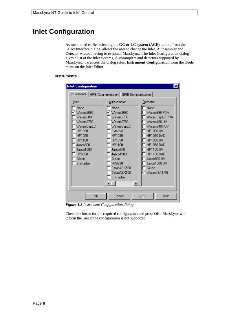
Inlet Configuration
As mentioned earlier selecting the GC or LC system (ACE) option, from theSelect Interface dialog, allows the user to change the Inlet, Autosampler andDetector without having to re-install MassLynx. The Inlet Configuration dialoggives a list of the Inlet systems, Autosamplers and detectors supported byMassLynx. To access the dialog select Instrument Configuration from the Toolsmenu on the Inlet Editor.
Instruments
Figure 1.3 Instrument Configuration dialog
Check the boxes for the required configuration and press OK. MassLynx willinform the user if the configuration is not supported.

MassLynx NT Guide to Inlet Control
Page 7
HPIB Communication
Figure 1.4 HPIB Communication dialog
When an Instrument configuration has been selected on the Instrument tab defaultdevice addresses are written to this dialog. Values can be changed if required. Forthe HP1100 DAD detector the PC Connection should be set to HP100 DAD.
GPIB Communication
Figure 1.5 GPIB Communication dialog
When an Instrument configuration has been selected on the Instrument tab defaultIDs are written to this dialog. These may need changing and will be defined onsetup by a Micromass engineer. For more information consult the relevantinstrument instruction manual.

MassLynx NT Guide to Inlet Control
Page 8

MassLynx NT Guide to Inlet Control
Page 9
Notes................................................................................................................................................................
................................................................................................................................................................
................................................................................................................................................................
................................................................................................................................................................
................................................................................................................................................................
................................................................................................................................................................
................................................................................................................................................................
................................................................................................................................................................
................................................................................................................................................................
................................................................................................................................................................
................................................................................................................................................................
................................................................................................................................................................
................................................................................................................................................................
................................................................................................................................................................
................................................................................................................................................................
................................................................................................................................................................
................................................................................................................................................................
................................................................................................................................................................
................................................................................................................................................................
................................................................................................................................................................
................................................................................................................................................................
................................................................................................................................................................
................................................................................................................................................................
................................................................................................................................................................
................................................................................................................................................................
................................................................................................................................................................
................................................................................................................................................................

MassLynx NT Guide to Inlet Control
Page 10
Notes................................................................................................................................................................
................................................................................................................................................................
................................................................................................................................................................
................................................................................................................................................................
................................................................................................................................................................
................................................................................................................................................................
................................................................................................................................................................
................................................................................................................................................................
................................................................................................................................................................
................................................................................................................................................................
................................................................................................................................................................
................................................................................................................................................................
................................................................................................................................................................
................................................................................................................................................................
................................................................................................................................................................
................................................................................................................................................................
................................................................................................................................................................
................................................................................................................................................................
................................................................................................................................................................
................................................................................................................................................................
................................................................................................................................................................
................................................................................................................................................................
................................................................................................................................................................
................................................................................................................................................................
................................................................................................................................................................
................................................................................................................................................................
................................................................................................................................................................
MassLynx NT Guide to Inlet Control
Page 11
Waters SystemsChapter 2
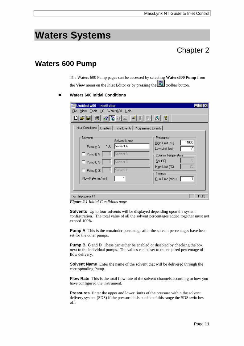
Waters 600 Pump
The Waters 600 Pump pages can be accessed by selecting Waters600 Pump from
the View menu on the Inlet Editor or by pressing the toolbar button.
n Waters 600 Initial Conditions
Figure 2.1 Initial Conditions page
Solvents Up to four solvents will be displayed depending upon the systemconfiguration. The total value of all the solvent percentages added together must notexceed 100%.
Pump A This is the remainder percentage after the solvent percentages have beenset for the other pumps.
Pump B, C and D These can either be enabled or disabled by checking the boxnext to the individual pumps. The values can be set to the required percentage offlow delivery.
Solvent Name Enter the name of the solvent that will be delivered through thecorresponding Pump.
Flow Rate This is the total flow rate of the solvent channels according to how youhave configured the instrument.
Pressures Enter the upper and lower limits of the pressure within the solventdelivery system (SDS) if the pressure falls outside of this range the SDS switchesoff.

MassLynx NT Guide to Inlet Control
Page 12
Column Heater If the instrument has an oven present then the columntemperature can be set to a specified temperature in degrees centigrade. Enter thetemperature to heat the column to in the Set box and a High Limit. If thetemperature exceeds the High Limit then the system will shut down. If the softwarehas been configured to operate without a column oven then these boxes will begreyed out.
Run Time Enter the time in minutes that the method will run from the point ofinjection.
n Waters 600 Gradient Page
Figure 2.2 Gradient page
This page allows a gradient to be entered and edited. To operate in isocratic modeensure that the timetable is empty.
To enable the B%, C% and/or D% boxes check the relevant boxes on theInitial Conditions page.
To add a gradient, enter a time and percentage in the relevant boxes and press the
toolbar button. Note: The first entry must have a time of 0.
To delete a single gradient, click with left mouse button on a time in the list and
press the toolbar button.
To delete all entries press the toolbar button. This button is only availablewhen there are entries in the timetable.
To modify a gradient, select the required entry in the timetable. The values will thenbe displayed in the edit boxes to the left of the timetable, and can be altered as
appropriate. Once changed press to re-enter the values into the timetable. If,however, you modify the time value such that it does not correspond to any existing
entry in the timetable pressing will result in a new entry being created in thetimetable.

MassLynx NT Guide to Inlet Control
Page 13
Flow Enter the flow rate for the solvent delivery system.
Curve This sets the rate at which the solvent is to change to the new proportionsand/or flow rates. See the Waters 600 Operator’s Guide for a list of values.
n Waters 600 Initial Events Page
Figure 2.3 Initial Events page
This page allows the initial state of switches 1 to 4 to be defined. Check the box(es)for the switches that should have an initial state of off.

MassLynx NT Guide to Inlet Control
Page 14
n Waters 600 Programmed Events Page
Figure 2.4 Programmed Events page
This page allows pump events to be entered and edited.
To add an event, type in a time, select an event from the drop down list box, select
an action or enter a value and press the toolbar button.
To delete a single event, click with left mouse button on a time in the list and press
the toolbar button.
To delete all entries press the toolbar button. This button is only availablewhen there are entries in the timetable.
To modify an event, select the required entry in the timetable. The values will thenbe displayed in the edit boxes above the timetable, and can be altered as appropriate.
Once changed press to re-enter the values into the timetable. If, however, youmodify the time value such that it does not correspond to any existing entry in the
timetable pressing will result in a new entry being created in the timetable.

MassLynx NT Guide to Inlet Control
Page 15
Waters 2690 Autosampler
Note: To control the Waters 2690 autosampler and pump from the keypad ratherthan the MassLynx software the Inlet must be configured as None. See Configuringthe Inlet System in the Acquisition Control Panel chapter.
n Waters 2690 Autosampler Initial Conditions Page
This page is used to set parameters specific to the Sampler, to access it select
Waters2690 AutoSampler from the View menu or press the toolbar button.
Figure 2.5 Autosampler Initial Conditions page
Sample Heater Temperature If the sample heater is installed, enter thetemperature that the sample should be to be heated or cooled to.Range: 4.0 to 40.0 °C.
Sample Heater Temperature Limit Enter the maximum deviation in sampletemperature allowed. If this is exceeded the current acquisition will stop and the LCStatus error light, on the MassLynx screen, will turn red. Range: ±1.0 to ±20.0 °C.
Injection Volume Enter the volume of sample to be injected, in microlitres.Range: 0 to 2000 µl. Note: If you are running from the Sample List, the injectionvolume in the sample list entry overrides the value entered here.
Needle Depth This adjusts the depth of the needle tip to accommodate forsedimented samples or non-standard vials. A value of 0 corresponds to the bottomof the vial. Range: 0.0 to 20.0 mm in 0.1mm increments.

MassLynx NT Guide to Inlet Control
Page 16
Draw Speed This determines the rate in microlitres per second at which sample isextracted into the autosampler needle. It should be set according to the viscosity ofthe sample. Select one of Fast, Normal or Slow from the dropdown list box. Thetable below shows the draw rate for each selection using a 250 µl syringe.
Selection Draw Rate for a 250 µl Syringe
Fast 5.0 µl/sec
Normal 2.5 µl/sec
Slow 1.0 µl/sec
Optional Sample Loop To inject sample volumes greater than 100 microlitres anadditional sample loop can be installed (in series with the existing sample loop),check this box if an additional sample loop is used.
Vial number The vial to inject from. Note: If a multisample acquisition is beingrun from the MassLynx Sample List, the Bottle # entry in the sample list overridesthe value entered here.
n Waters 2690 Autosampler Purge Page
This page is used to set the Autosampler purge volume, to access it click on theAutosampler Purge tab.
Figure 2.6 Autosampler Purge page
Loop Volumes Enter the number of times the loop should be filled to purge thesample loop and syringe of traces of the previous sample. When set to a valuegreater than zero, this action is performed after every injection.

MassLynx NT Guide to Inlet Control
Page 17
Waters 2690 Pump
Note: To control the Waters 2690 autosampler and pump from the keypad ratherthan the MassLynx software the Inlet must be configured as None. See Configuringthe Inlet System in the Acquisition Control Panel chapter.
The Waters Pump pages can be accessed by selecting Waters2690 Pump from the
View menu on the Inlet Editor or by pressing the toolbar button.
n Waters 2690 Solvents and Flows Page
Figure 2.7 Solvents and Flows page
Solvents Up to four solvents will be displayed depending upon the systemconfiguration. The total value of all the solvent percentages added together mustequal 100%. Solvent Names entered here will be displayed on the Pump Gradientpage.
Pump A This displays the remainder percentage after the solvent percentages havebeen set for the other enabled pumps.
Pump B, C and D These can either be enabled or disabled by checking the boxnext to the individual pumps. The values can be set to the required percentage offlow delivery.
Run Time This value is set to the time in minutes that the method will run fromthe point of injection.
Degasser This value is set to the time in minutes that the method will run fromthe point of injection.
Flow This is the total flow rate for the system.
Flow Ramp Enter the time (in minutes) for the solvent delivery system to reachthe maximum system flow rate (10 ml/min). Recommended minimum setting:0.5 min.

MassLynx NT Guide to Inlet Control
Page 18
n Waters 2690 Column Setup Page
Figure 2.8 Column Setup page
Column Heater Temperature Enter the target operating temperature for theoptional column heater. This value must be at least 5 °C above ambient.Range: 20 to 60 °C.
Column Heater Temperature Limit This is the maximum deviation in columntemperature allowed. If this is exceeded the current acquisition will stop and the LCStatus error light, on the MassLynx screen, will turn red. Range: ±1 to ±20 °C.
Enter Low Pressure and High Pressure values as required. If the pressure fallsoutside these limits the current acquisition will stop and the LC Status error light, onthe MassLynx screen, will turn red. Low Pressure Range: 0 to 310 bar. LowPressure Range: 0 to 345 bar.
Pre-column Volume Enter the volume of solvent to pump through the columnbefore an injection. Range: 1 to 10000 µl.
MassLynx NT Guide to Inlet Control
Page 19
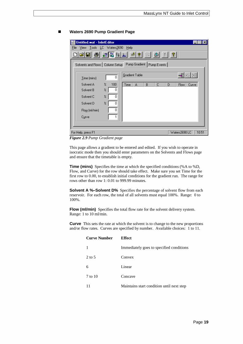
n Waters 2690 Pump Gradient Page
Figure 2.9 Pump Gradient page
This page allows a gradient to be entered and edited. If you wish to operate inisocratic mode then you should enter parameters on the Solvents and Flows pageand ensure that the timetable is empty.
Time (mins) Specifies the time at which the specified conditions (%A to %D,Flow, and Curve) for the row should take effect. Make sure you set Time for thefirst row to 0.00, to establish initial conditions for the gradient run. The range forrows other than row 1: 0.01 to 999.99 minutes.
Solvent A %–Solvent D% Specifies the percentage of solvent flow from eachreservoir. For each row, the total of all solvents must equal 100%. Range: 0 to100%.
Flow (ml/min) Specifies the total flow rate for the solvent delivery system.Range: 1 to 10 ml/min.
Curve This sets the rate at which the solvent is to change to the new proportionsand/or flow rates. Curves are specified by number. Available choices: 1 to 11.
Curve Number Effect
1 Immediately goes to specified conditions
2 to 5 Convex
6 Linear
7 to 10 Concave
11 Maintains start condition until next step

MassLynx NT Guide to Inlet Control
Page 20
Curve Profiles
n Waters 2690 Gradient Table Operation
To add a gradient, enter values in the relevant boxes and press the toolbarbutton. You can add up to 15 rows to the table. Note: The first entry must have atime of 0.
To delete a single gradient, click with left mouse button on a time in the list and
press the toolbar button.
To delete all entries press the toolbar button. This button is only availablewhen there are entries in the timetable.
To modify a gradient, select the required entry in the timetable. The values will thenbe displayed in the edit boxes above the timetable, and can be altered as appropriate.
Once changed press to re-enter the values into the timetable. If, however, youmodify the time value such that it does not correspond to any existing entry in the
timetable pressing will result in a new entry being created in the timetable.

MassLynx NT Guide to Inlet Control
Page 21
n Waters 2690 Pump Events Page
Figure 2.10 Pump Events page
This page allows pump events to be entered and edited.
Use the Event Table to program up to 16 events (both external and internal). Theexternal events are triggered by four contact closures (relays) through outputterminals (S1–S4) on the 2690 Separations Module. The internal events are used tocontrol the sample compartment temperature and column heater temperature, and toprime and flush the 2690 Separations Module. Events can be triggered more thanonce and multiple events can be triggered simultaneously.
Time Enter the time at which the event should start. Event rows are sortedautomatically by time. Note: Different events can be programmed to occur at thesame time. Range: 0.00 to 999.99 min.
Event Enter the type of event signal required: one of the four TTL-level outputswitches (S1–S4), or one of the internal events (column heater temperature, samplecompartment temperature or flush/prime). Available choices:
• Switch 1 to Switch 4 Corresponds to terminal strip positions S1 to S4 on therear of the 2690 module. Activating a Switch event triggers a contact closurefor controlling an external device. After selecting a switch event, set a state forthe switch by selecting On, Off, Toggle, Pulse Width or No Change. This stateappears in the Action column of the table (refer to Switch States, below). Note:If Pulse is selected for a switch state, the duration of the pulse must be enteredin the Width (min) field.
• Set Temperature (Column or Sample) Specifies the temperature of anoptional column heater, or an optional sample compartment heater/cooler.After selecting this event, select Column or Sample and enter the requiredTemperature in °C. Note: When a Column Temperature event occurs, thetemperature of the column heater changes from the value set in the Heaters andPressures page to the value set for the event. When the event times out, thetemperature changes back to the Heaters and Pressures page value. Columnrange: 20 to 60 °C. Sample range: 4 to 40 °C.

MassLynx NT Guide to Inlet Control
Page 22
• Flush/Prime Specifies a flush/prime operation for the 2690 module. Use thisevent only when creating Inlet Pre-run and Inlet Post-run methods. Thesemethods will use the solvent percentages and the run time from the Solvents andFlows page but will use the Flow value entered on this page. Note: The Timefield is not accessible when you select a Flush/Prime event.
Switch States
• On – Turns on a contact closure that triggers an external or internal event. Withthis function, the contact closure remains closed until an Off function is sent.
• Off – Turns off the contact closure for the event. With this function, the contactclosure is broken.
• Pulse – Transmits a single On/Off pulse. The contact closure is maintained forthe number of seconds defined in the Value column. Range: 0.01 to 10.00 sec.
• Toggle – Changes the current state of the switch.
• No Change – Leaves the switch in its current state.
n Waters 2690 Event Table Operation
To add an event, enter a time, select an event from the drop down list box, select an
action and press the toolbar button. Up to 16 events can be programmed.
To delete a single event, click with left mouse button on a time in the list and press
the toolbar button.
To delete all entries press the toolbar button. This button is only availablewhen there are entries in the timetable.
To modify an event, select the required entry in the timetable. The values will thenbe displayed in the edit boxes above the timetable, and can be altered as appropriate.
Once changed press to re-enter the values into the timetable. If, however, youmodify the time value such that it does not correspond to any existing entry in the
timetable pressing will result in a new entry being created in the timetable.

MassLynx NT Guide to Inlet Control
Page 23
Waters 996 PDA Detector
This page is used to set parameters specific to the UV detector, to access it select
Waters996 PDA Detector from the View menu or press the toolbar button.
n Waters 996 PDA Page
Figure 2. 11 UV Detector Configuration page
Start Wavelength Enter the wavelength at which to start acquiring data.
End Wavelength Enter the wavelength at which to stop acquiring data.
The range with Resolution set to 1.2 is 190.0 nm to 800.0 nm. The range at all otherResolution settings is 190.0 + (Resolution/2) to 800.0 (Resolution/2).
Resolution Enter the number of diodes that are averaged together as a singlespectral data point. To differentiate closely related spectra and obtain greaterspectral resolution, use a small resolution number. Be aware, however, that a smallresolution value generates more data points and therefore requires more disk spacethan a large resolution value. Find a resolution value just small enough to identifyspectral features. Range: 1.2 to 24.0 nm in multiples of 1.2.
Sampling Rate Select the number of Spectra to be acquired per second, from thedropdown list box. For good integration and quantitation, acquire 15 to 20 spectraacross a peak.
Auto Exposure Check this box to enable the detector optics to calculate theoptimum exposure time needed to recharge the diodes, based on the lamp energy,the lamp spectrum and the selected wavelength range. Tip: Enable Auto Exposurefor most routine analyses.
Interpolate Check this box to instruct the detector to ignore the signal from thephotodiode at 656 nm and interpolate a value from the adjacent diodes. Thisprevents over-saturation at 656 nm (Balmer line for deuterium). Only applicable ifthe Auto Exposure option has been selected.

MassLynx NT Guide to Inlet Control
Page 24
If this box is not checked the detector reports the signal from the photodiode at656 nm, this is only necessary if you are working with compounds that absorb in the656 nm range.
Note: If this parameter is unchecked, the deuterium lamp high emission line at 656nm may cause spectral artifacts and autoexposure errors.
Exposure Time The exposure time is the time that the photodiodes are exposed tolight before they are read. To set a different Exposure Time, ensure that the AutoExposure box is not checked and enter the required time in milli seconds.Range: 11.00 to 500.00 ms.
Stop Time To specify a different Acquisition Stop Time enter the time in minuteswhen the PDA should stop scanning.
Filter Response Enter the response time for filtering acquired data. The filter isan enhanced rolling average filter applied to absorbance data from the PDA detectorbefore the data is sent to MassLynx. The filter reduces high-frequency noise acrossthe entire wavelength range specified for the acquisition. High values decrease peakresponse. Available choices: 0, 1, 2 and 3.
Save to Disk Check this box to save the Photo Diode Array data to the rawdatafile. If this data is not required for further processing then uncheck the box, thedata is not saved to disk thus reducing the size of the file.
n Waters 996 Channel Detector Configuration Pages
The Channel 1 and Channel 2 pages contain the same information. Select the pagerelevant to the channel required, by clicking on the tab.
Figure 2.12 Channel 1 Detector Configuration page
MassLynx NT Guide to Inlet Control
Page 25
Output Mode Select one of
• Off – no analog output signal.
• Absorbance – Output is in absorbance units at the wavelength specified.Note: Ratio Denominator Wavelength and Threshold parameters are notaccessible when Absorbance mode is selected.
• Ratio – Output represents the ratio of absorbances at two wavelengths. Thenumerator wavelength is specified by the Wavelength parameter, and thedenominator wavelength is specified by the Ratio Denominator Wavelengthparameter (see below).
Wavelength Enter the output wavelength to monitor. In Ratio mode, theabsorbance at the Wavelength is used to calculate ratio in the formula:
Ratio = Absorbance at Wavelength/Absorbance at Ratio DenominatorWavelength
Wavelength must be within the wavelength range specified by the Start Wavelengthand End Wavelength parameters on the PDA page.
Range when Resolution is set to 1.2: Start Wavelength to End Wavelength.Range at all other Resolution settings: Start Wavelength + (Bandwidth/2) to EndWavelength – (Bandwidth/2). Default: 254 nm.
Ratio Denominator Wavelength Enter the denominator wavelength (innanometers) for the analog output channel. Ratio Denominator Wavelength must bewithin the wavelength range specified by the Start Wavelength and End Wavelengthparameters on the 996 PDA page.
Bandwidth Enter the spectral bandwidth of the analog output channel. The rangeis 1.2 to 24.0 nm.
Filter Type Select Hamming or Single Pole from the dropdown list box. TheHamming filter is designed to create the same degree of peak-height degradation asthe Single Pole filter for the same response time, but enhances filtering ofhigh-frequency noise.
Filter Response Enter the response time for the filter. The range is 0 to 5seconds.
Offset If required enter an offset to the analog output channel. The range is –0.2 to2.0 AU.
Threshold Enter a threshold above which the ratio (Wavelength / RatioDenominator Wavelength) must be to be valid data. The range is –0.1 to 2.0 AU.
Note: If no ratio is plotted one or both channels are below the current Thresholdand a lower Threshold value should be entered.

MassLynx NT Guide to Inlet Control
Page 26
Waters 486 UV Detector
This page is used to set parameters specific to the UV detector, to access it select
Waters486 UV Detector from the View menu or press the toolbar button.
Figure 2.13 486 UV Detector Configuration page
Wavelength (µ) Enter the wavelength to monitor.
Polarity Select the polarity of the output signal from the drop down list box.
Sensitivity (AUFS) Enter the required sensitivity of the output signal.
Time Filter (seconds) Enter the response time for filtering acquired data.
A full description of all the parameters in this editor is given in theWaters 486 Instruction Manual.

MassLynx NT Guide to Inlet Control
Page 27
Waters 2487 UV Detector
This page is used to set parameters specific to the Waters 2487 UV detector, to
access it select Waters2487 UV Detector from the View menu or press the toolbar button.
2487 Single Wavelength Absorbance Detector
The 2487 detector can be used as a single or dual wavelength detector. To use as asingle wavelength detector select Single Wavelength from the Waters2487UVmenu. A tick mark will appear next to the name if single wavelength is selected andthe 2487 Channel B parameters are greyed out.
Figure 2.14 2487 UV Detector Configuration page (Single Wavelength)
Wavelength (µ) Enter the wavelength to monitor.
Sensitivity (AUFS) Enter the required sensitivity of the output signal.
Time Filter (seconds) Enter the response time for filtering acquired data.
Polarity Select the polarity of the output signal from the drop down list box.
A full description of all the parameters in this editor is given in theWaters 2487 Instruction Manual.
2487 Dual Wavelength Absorbance Detector
The 2487 detector can be used as a single or dual wavelength detector. To use as adual wavelength detector ensure that the Single Wavelength option on theWaters2487UV menu is not selected. If a tick mark appears next to the name thensingle wavelength is selected, selecting the option again will return the detector todual wavelength mode and both channel parameters will be available.
The parameters are the same as for single wavelength mode.

MassLynx NT Guide to Inlet Control
Page 28
Waters 2487 IEEE Detector
The 2487 IEEE Detector should be selected if the detector is connected via a GPIBcard in the back of the PC.
The 2487 IEEE Detector is used to collect binary data, through the IEEE interface,rather than through the analog interface.
This page is used to set parameters specific to the Waters 2487 IEEE detector, to
access it select Waters2487 IEEE Detector from the View menu or press the toolbar button.
n 2487 Dual Absorbance Detector
The 2487 detector can be used as a single or dual wavelength detector. To use as asingle wavelength detector select Single Wavelength from the Waters2487UVmenu. A tick mark will appear next to the name if single wavelength is selected andthe 2487 Channel B parameters are greyed out.
Figure 2.15 2487 UV Detector Configuration page (Single Wavelength)
Wavelength (µ) Enter the wavelength to monitor.
Sensitivity (AUFS) Enter the required sensitivity of the output signal.
Time Filter (seconds) Enter the response time for filtering acquired data.
Polarity Select the polarity of the output signal from the drop down list box.
A full description of all the parameters in this editor is given in theWaters 2487 Instruction Manual.
MassLynx NT Guide to Inlet Control
Page 29
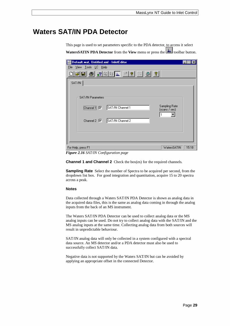
Waters SAT/IN PDA Detector
This page is used to set parameters specific to the PDA detector, to access it select
WatersSATIN PDA Detector from the View menu or press the toolbar button.
Figure 2.16 SAT/IN Configuration page
Channel 1 and Channel 2 Check the box(es) for the required channels.
Sampling Rate Select the number of Spectra to be acquired per second, from thedropdown list box. For good integration and quantitation, acquire 15 to 20 spectraacross a peak.
Notes
Data collected through a Waters SAT/IN PDA Detector is shown as analog data inthe acquired data files, this is the same as analog data coming in through the analoginputs from the back of an MS instrument.
The Waters SAT/IN PDA Detector can be used to collect analog data or the MSanalog inputs can be used. Do not try to collect analog data with the SAT/IN and theMS analog inputs at the same time. Collecting analog data from both sources willresult in unpredictable behaviour.
SAT/IN analog data will only be collected in a system configured with a spectraldata source. An MS detector and/or a PDA detector must also be used tosuccessfully collect SAT/IN data.
Negative data is not supported by the Waters SAT/IN but can be avoided byapplying an appropriate offset in the connected Detector.

MassLynx NT Guide to Inlet Control
Page 30
Waters 2700 Autosampler
These pages are used to set parameters specific to the autosampler, to access them
select Waters2700 AutoSampler from the View menu or press the toolbarbutton.
n Waters 2700 Injection Configuration
Figure 2.17 Waters 2700 Sampler Injection Configuration Page
Loop Volume (µl) Enter the volume of the sample loop in microlitres.
Injection Volume (µl) Enter the volume of the sample to inject into the loop forsingle sample acquisitions. For samples acquired via a sample list this is overriddenby the value in the sample list. If the Injection Volume is equal to the Loop Volumethen twice the Injection Volume is drawn to ensure that the loop is full.
Separation Air Gap (µl) Enter the volume of air to draw before the sample.
Vial Enter the position of the vial to use for single sample acquisitions. Forsamples acquired via a sample list this is overridden by the value in the sample list.

MassLynx NT Guide to Inlet Control
Page 31
n Waters 2700 Dilutor Configuration
Figure 2.18 Waters 2700 Sampler Dilutor Configuration Page
Syringe Size Select the size of the syringe installed from the drop down list box.
Aspiration Speed Enter a value for the speed at which to draw the sample intothe needle (the pump will be on its downward journey). Range: 1 to 32, with 1being the fastest.
Dispense Speed Enter a value for the speed at which to eject the sample from theneedle (the pump will be on its upward journey). Range: 1 to 32, with 1 being thefastest.
n Waters 2700 Wash Parameters
Figure 2.19 Waters 2700 Sampler Wash Parameters Configuration Page

MassLynx NT Guide to Inlet Control
Page 32
Needle Rinse Volume (µl) Enter the volume of mobile phase required to washthe needle after an injection. A value of zero will result in no wash. If the needlerinse volume is greater than 800µl then the mini-wash pump is used instead.
Wash Time (seconds) Enter the time for which the mini-wash pump is activatedduring a mini-wash prime. Mini-wash prime is activated from the Waters2700menu.
Injection Port Flush Volume (µl) Enter the volume of mobile phase required toflush the inject port after the sample has been injected. A value of zero will result inno port flush.
Injection Port Flush Speed Enter the speed at which the flush volume isdispensed. Range: 1 to 32, with 1 being the fastest.
n Waters 2700 Sample Configuration
Figure 2.20 Waters 2700 Sampler Configuration Page
Current Layout This shows the currently selected rack configuration. To changethe current layout select a new one from the drop down list box.

MassLynx NT Guide to Inlet Control
Page 33
Waters 2700 Bed Layout
Bed layouts are created, deleted or amended from this dialog. To display theBed Layout Editor dialog, select Bed Layout from the Waters2700 menu.
Figure 2.21 Bed Layout Dialog
n To Create A New Bed Layout (Waters 2700)
1. Highlight a bed layout similar to the one you want to create and press the
button to create a new layout. The layout appears in the Bed Layoutslist as the same name with a 1 at the end, e.g. Six Position Microtiter1.
2. To change the name of the layout, type the new name into the Bed Layouts
text box and press the button. The name is updated in the Bed Layoutslist box.
New bed layouts are saved to the MassLynx Racks directory.
n To Delete A Bed Layout (Waters 2700)
1. Highlight the bed layout to delete and press the button. A dialog box willask you to confirm the deletion. Press the OK button to delete the bed layout.Note: The bed layout which is selected as the current bed layout on theSampler Configuration page cannot be deleted.

MassLynx NT Guide to Inlet Control
Page 34
n Other Bed Layout Options (Waters 2700)
1. To change the number of rows in the current column, type the new number into
the Rows box and press the button.
2. To append a new column, press the button.
3. To delete the current column press the button.
4. To insert a column, click on the column before which you want to insert and
press the button. Note: The column inserted will have the same numberof rows as the column highlighted.
n Modify Bed Layout (Waters 2700)
If the plate position or type needs changing select the Modify Bed Layout tab.
Figure 2.22 Modify Bed Layout Dialog
Click on one of the code plates to display the Plate Position and Type dialog.

MassLynx NT Guide to Inlet Control
Page 35
Figure 2.23 Plate Position and Type dialog
This dialog allows you to select a new plate from a list of possible options, andchange its actual position on the bed. Measurements for plate positions are alwaystaken from the top left corner of each plate. The X value is the measurement fromthe vial position in the top left corner of the plate to the home position. The Y valueis the measurement from the vial position in the top left corner of the plate to thehome position.
Vial bottom from probe home This is the distance the needle must traveldownwards to reach the bottom of the well.
OpenLynx plate login If this box is checked and Use current MassLynxautosampler bed layout is checked in the OpenLynx Manager program, then theplate at this position can only be used for plate login on the OpenLynx Loginprogram.
Pressing the button will move the needle to the top left vial position defined bythe X, Y and Vial bottom from probe home positions. If the needle is not above thetop left vial then the plate will need moving or the X and Y values will needchanging.
Pressing the button will take the needle to the bottom right vial position (Thesoftware will calculate this from the plate type and the X and Y positions defined).This is used to test that the plate will fit on the autosampler, if it does not then anerror message is displayed. The plate will need changing or moving or the X and Yvalues will need changing.
MassLynx NT Guide to Inlet Control
Page 36
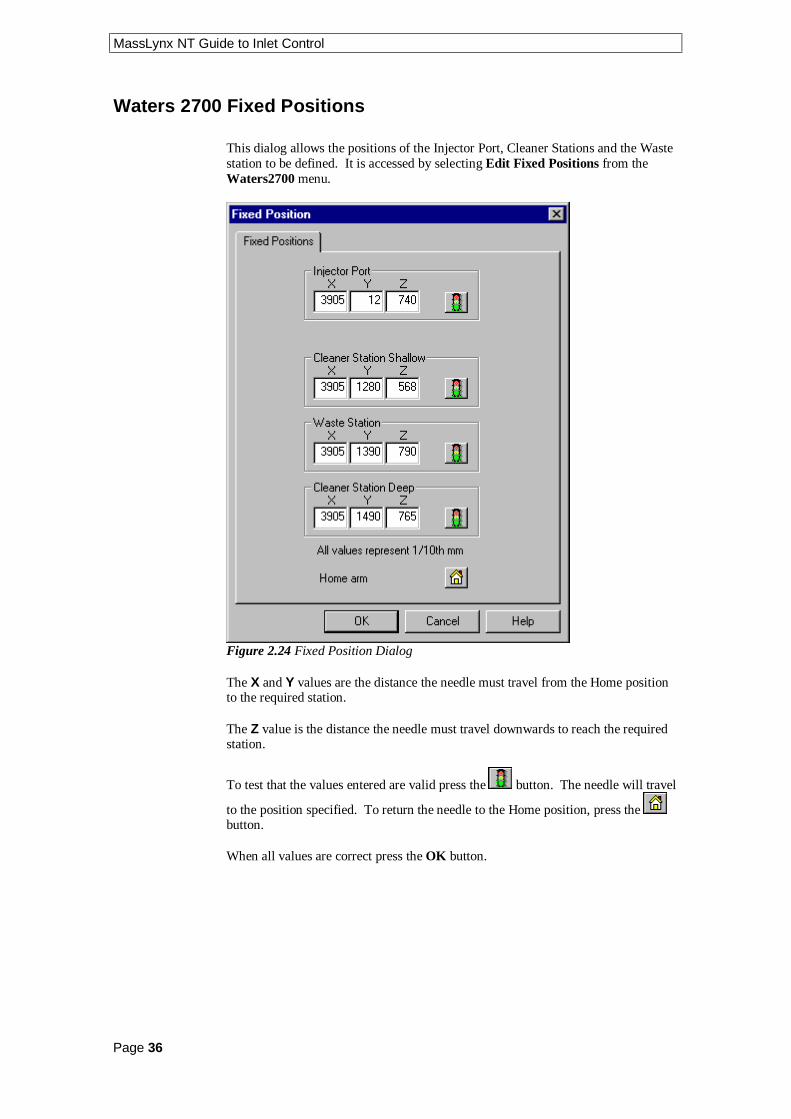
Waters 2700 Fixed Positions
This dialog allows the positions of the Injector Port, Cleaner Stations and the Wastestation to be defined. It is accessed by selecting Edit Fixed Positions from theWaters2700 menu.
Figure 2.24 Fixed Position Dialog
The X and Y values are the distance the needle must travel from the Home positionto the required station.
The Z value is the distance the needle must travel downwards to reach the requiredstation.
To test that the values entered are valid press the button. The needle will travel
to the position specified. To return the needle to the Home position, press the button.
When all values are correct press the OK button.

MassLynx NT Guide to Inlet Control
Page 37
Waters 2700 Plate Generator
To display the Plate Generator dialog, select Plate Generator from the Waters2700menu.
Figure 2.25 Plate Generator
Plate Name The name of the plate that is currently being edited.
Rows The number of vials in a row and the distance between each center.
Columns The number of vials in a column and the distance between each center.
Offsets Allows alternate vial rows or columns to be offset. Note: Entering apositive value will shift even numbered rows to the right and negative values willshift even numbered rows to the left.
Vial Reference Allows the user to select the way that the vial rows and columnsare referenced, e.g. whether the rows are alphabetical or numerical.
Referencing This has three options
• XY which references the vials A1, B1 etc.
• Sequential Discontinuous which numbers the vials 1, 2, 3 across a row, left toright, and then starts the next row from the left again.
• Sequential Continuous which numbers the vials 1, 2, 3 across a row, left toright, then continues number the next row, right to left etc.
If the Waters 2700 autosampler is used with OpenLynx then the vial referencingmust be set to either sequential continuous or sequential discontinuous.

MassLynx NT Guide to Inlet Control
Page 38
Priority Check the Horizontal First box if samples are to be acquired horizontallyacross the plate.
If Referencing = X,Y, Horizontal = Letter, Vertical = Number andHorizontal Priority is checked, this will result in samples being acquired in the orderA1, A2, A3. If the Horizontal Priority box is not checked samples will be acquiredin the order 1A, 1B, 1C etc.
If Referencing = sequential continuous or discontinuous and Horizontal Priority ischecked, this will result in samples being acquired from row 1 then row 2. If theHorizontal Priority box is not checked samples will be acquired from column 1 thencolumn 2 etc.
Plate Size The size of the plate to its outside edges.
Top Left Vial Offset The measurement to the center of the first vial from the topleft corner of the plate.
Vial The depth and diameter values are used for display only. They appear in thedescription for a single shot login on the OpenLynx Login screen.
n Creating and Deleting Waters 2700 Plates
To create a new plate, press the button. A new default plate is displayed,
change the Plate Name, enter the appropriate values and press the save buttonor select Save Plate from the Plate menu. New plates are saved to the MassLynxPlates directory.
To copy a plate, page through the list of saved plates using the and toolbar buttons. The Previous Plate and Next Plate options on the Plate menuperform the same operation. When the required plate is displayed change the Plate
Name, enter the appropriate values and press the save button or select SavePlate from the Plate menu. New plates are saved to the MassLynx Plates directory.
To delete a plate select the plate, by typing the name in the Plate Name box or by
paging through as above, and press the delete button or choose Delete Platefrom the Plate menu.
Note: All of the spacings and the vial section are stored in 0.1mm units.
Note: When defining a custom plate for use with a multi-injector the plate isrequired to be compatible with the position of the 8 needles of the autosampler.
• The Plate must have eight columns.
• The position of the vials should allow all eight needles to enter a separate vial.
• There should be no odd or even offsets for any of the vial positions.
Note: If the Plate currently selected on the Sample Configuration page is changedhere, then Reset Injector should be selected from the LC menu to resetcommunications.

MassLynx NT Guide to Inlet Control
Page 39
Waters 2700 Menu
Prime Syringe This option is used to remove air from the syringe and any tubingconnected to it. It repeatedly draws the mobile phase into the needle and flushes it
out until the toolbar button is pressed, or Stop Method is selected from theLC menu, on the Inlet Editor. Note: Before Prime Syringe is selected the toolbar
button appears as and the menu as Run Method.
Change Syringe Selecting this option moves the needle to a position where it canbe removed and replaced. When the syringe has been changed, Prime Syringeshould then be selected to get the needle into a state ready for injection.
Prime Mini-Wash This option moves the needle to the waste position and pumpsthe mobile phase through it for the Wash Time defined on the Wash Parameterspage.

MassLynx NT Guide to Inlet Control
Page 40
Waters 2790 Autosampler
Note: To control the Waters 2790 autosampler and pump from the keypad ratherthan the MassLynx software the Inlet must be configured as None. See Configuringthe Inlet System in the Acquisition Control Panel chapter.
These pages are used to set parameters specific to the Sampler, to access them select
Waters2790 AutoSampler from the View menu or press the toolbar button.
n Waters 2790 Injection Parameters Page
Figure 2.26 Injection Parameters page
Inject Type Select Sequential or Parallel from the drop down list box.
Sequential – Sample aspiration occurs at the start of each injection cycle,after completion of the previous injection.
Parallel – Sample aspiration and loop fill occur concurrently with otherseparation method functions for higher throughput.
Fill Mode Select Full Loop or Partial Loop from the drop down list box.
Full Loop – The autosampler draws in the loop volume the overfill factornumber of times, to ensure that the loop is full.
Partial Loop – The autosampler will draw in the volume specified in thesample list and centre it in the loop.
Aspirate Air Pre-sample Enter the volume of air to be drawn into the needlebefore the sample, to separate it from the previous sample. Range: 0 to half the loopsize.
Aspirate Air Post-sample Enter the volume of air to be drawn into the needleafter the sample, to separate it from the next sample. Range: 0 to half the loop size.

MassLynx NT Guide to Inlet Control
Page 41
Loop Off-line Time For Parallel Injection mode, enter the time in minutes whenthe injector valve is switched back from the inject position to the load position forthe next sample to be preloaded into the sample loop. Range 0.00 to the Run Timedefined on the Pump Mobile Phase page, in minutes.
Overfill Factor For full loop mode enter the number of times to draw the loopvolume into the loop to ensure that it is full. Range 1.0 to 20.
n Waters 2790 Autosampler Parameters Page
Figure 2.27 Autosampler Parameters page
Sample Temperature Set If the sample heater is installed, enter the temperatureto heat or cool the sample to. Range: 4.0 to 40.0 °C.
Sample Temperature Limit This is the maximum deviation in sampletemperature allowed. If this is exceeded the current acquisition will stop and the LCStatus error light, on the MassLynx screen, will turn red. Range: ±1.0 to ±20.0 °C.
Loop Size (µl) This is a display only field showing the volume of the sample loopinstalled.
Syringe Size This is a display only field showing the size of the syringe installed.
Draw Depth Adjusts the depth of the needle tip to accommodate for sedimentedsamples or non-standard vials. A value of 0 corresponds to the bottom of the vial.Range: 0.0 to 20.0 mm.

MassLynx NT Guide to Inlet Control
Page 42
Draw Speed This determines the rate in microlitres per second at which sample isextracted into the autosampler needle. This should be set according to the viscosityof the sample. Select one of Fast, Normal or Slow from the dropdown list box.The table below shows the draw rate for each selection using a 250 µl syringe.
Selection Draw Rate for a 250 µl Syringe
Fast 5.0 µl/sec
Normal 2.5 µl/sec
Slow 1.0 µl/sec
Custom Value entered in the Custom Speed box.
Seek Well Bottom If this box is checked then, for the first well on a plate, theneedle will automatically seek the bottom of the well before drawing the sample.The depth of the well will be saved by the software and used as the depth for allother wells on the plate. This will be repeated for the first well on each plate. Note:If a value has been entered in the Draw Depth field then this operation will not beperformed.
Check Plate Height If this box is checked, for the first injection from a plate, aneedle positioning sensor determines the plate height then checks it against the PlateSize, Z value defined in the Plate Generator.
n Waters 2790 Wash Parameters Page
Figure 2.28 Wash parameters page
Wash Frequency Select the wash frequency from the drop down list box.
• None Do not perform a wash.
• Inject Perform a wash after each injection.
• Well Perform a wash after all samples have been taken from the current well.

MassLynx NT Guide to Inlet Control
Page 43
Inject Port Enter the time in seconds to wash the interior of the needle for.
Needle Exterior Enter the time in seconds to wash the exterior of the needle for.Range: 0 to 99 seconds.
Wash Cycles Enter the number of times the Inject Port and Needle Exteriorwashes are to be performed. Range: 0 to 10.
Replacement Volume Enter the volume of wash solvent to leave in the needleafter the wash/flush operation has been performed. This volume is then drawnthrough the waste valve and dispensed into the sample line through the needle.5DQJH����WR������ O�

MassLynx NT Guide to Inlet Control
Page 44
Waters 2790 Pump
Note: To control the Waters 2790 autosampler and pump from the keypad ratherthan the MassLynx software the Inlet must be configured as None. See Configuringthe Inlet System in the Acquisition Control Panel chapter.
The Waters Pump pages can be accessed by selecting Waters2790 Pump from the
View menu on the Inlet Editor or by pressing the toolbar button.
n Waters 2790 Mobile Phase Page
Figure 2.29 Mobile Phase page
Solvents Up to four solvents will be displayed depending upon the systemconfiguration. The total value of all the solvent percentages added together mustequal 100%. Solvent Names entered here will be displayed on the Gradient page.
Pump A This displays the remainder percentage after the solvent percentages havebeen set for the other enabled pumps.
Pump B, C and D These can either be enabled or disabled by checking the boxnext to the individual pumps. The values can be set to the required percentage offlow delivery.
Flow Enter the total initial flow rate of the system. Range: 0.000 to 10.000ml/min.
Ramp Enter the time (in minutes) for the solvent delivery system to reach themaximum system flow rate (10 ml/min). This limits the rate of change of the flowrate to protect the column from potentially damaging sudden changes in pressure.Range: 0.01 to 30 minutes. Recommended minimum setting: 0.5 min.
Enter Low Pressure Limit and High Pressure Limit values as required. If thepressure falls outside these limits the current acquisition will stop and the LC Statuserror light, on the MassLynx screen, will turn red. Low Pressure Range: 0 to 310bar. High Pressure Range: 0 to 345 bar.

MassLynx NT Guide to Inlet Control
Page 45
Degasser Select one of Off, Normal or Continuous from the drop down list box.
• Off The degasser is always off.
• Normal The degasser cycles on and off.
• Continuous The degasser is always on.
Stroke Length This sets the volume of solvent delivered for each piston stroke.Select the required option from the drop down list box. If Auto is selected then thevolume is automatically adjusted to provide optimal performance for the selectedsolvent flow rate, otherwise the volume selected will be used.
Run Time Enter the time in minutes that the method will run from the point ofinjection.
Note: Run time is for the solvent delivery system only. Detectors have independentrun times. The MS method (Scan Function Editor) run time must be greater than allother run times.
n Waters 2790 Column Page
Figure 2.30 Column page
Position This field allows the column to be selected for the method. The optionsavailable will depend on the column setup on the Waters 2790 Separations Module.
If only one column is installed then this box will display Column 1 and cannot bechanged. For other configurations this box will allow the selection of a column(between 1 and 6 depending on configuration) or No change from the drop down listbox. Selecting a numbered column will use this column for the method, selectingNo Change will use the column defined in the last method used to acquire a sample.See the Waters 2790 Separations Module Operator’s Guide for more information onthe column selection valve.

MassLynx NT Guide to Inlet Control
Page 46
Equilibrium Time Enter the time required to reach equilibrium (i.e. run in initialconditions), before performing an injection, after a column change. Range: 0.00 to999.99 minutes.
Temperature Set Enter the target operating temperature for the optional columnheater. This value must be at least 5 °C above ambient. Range: 20 to 60 °C.
Temperature Limit Enter the maximum deviation in column temperatureallowed. If this is exceeded the current acquisition will stop and the LC Status errorlight, on the MassLynx screen, will turn red. Range: ±1 to ±20 °C.
n Waters 2790 Rapid Equilibration Page
Figure 2.31 Rapid Equilibration page
Path Select the path to be used for flushing solvent during rapid equilibration fromthe drop down list box. Waste, Off or Column 1 to Column 6 depending on theinstrument configuration.
Flow Enter the system equilibration flow rate. Range: 0.00 to 10.00 ml/min.
Time Enter the length of time (in minutes) to equilibrate. Range 0.00 to 999.99minutes.
Re-equilibration Time Enter the time that column should be maintained at initialflow/composition conditions after completion of a gradient run. This delay isimposed on a per injection basis if defined.
Pre-column Volume Enter the volume of solvent to pump through the columnbetween the time the gradient starts and the time of injection. Range: 0.0 to10000.0 µl.

MassLynx NT Guide to Inlet Control
Page 47
n Waters 2790 I/O Page
Figure 2.32 I/O page
Switch Initial Conditions Select the state that switches 1 to 4 should be ininitially, from the drop down list box. At the beginning of each injection cycle eachswitch returns to the state defined here. Available choices:
• On – Turns on a contact closure that triggers an external or internal event. Withthis function, the contact closure remains closed until an Off function is sent.
• Off – Turns off the contact closure for the event. With this function, the contactclosure is broken.
• Pulse – Transmits a single On/Off pulse. The contact closure is maintained forthe number of minutes set in the Pulse Width field on the Events page. Range:0.01 to 100.00 sec.
• Toggle – Changes the current state of the switch.
• No Change – Leaves the switch in its current state.
Chart Output Setting Select Flow Rate, System Pressure, %A, %B, %C,%D, Column Temperature or Sample Temperature from the drop down list box.
The Analog output signals are sent through the terminals on the back of the 2790, toan optional analog device such as a strip chart recorder. If, for example, SystemPressure is selected the recorder will chart the system pressure while the method isbeing run.

MassLynx NT Guide to Inlet Control
Page 48
n Waters 2790 Gradient Page
Figure 2.33 Gradient page
This page allows a gradient to be entered and edited. If you wish to operate inisocratic mode then enter parameters on the Mobile Phase page and ensure that thetimetable is empty.
Time (mins) Specifies the time at which the specified conditions (%A to %D,Flow, and Curve) for the row should take effect. Make sure the Time for the firstrow is set to 0.00, to establish initial conditions for the gradient run. The range forrows other than row 1is 0.01 to 999.99 minutes.
Solvent A % - Solvent D% Specifies the percentage of solvent flow from eachreservoir. For each row the total of all solvents must equal 100%. Range: 0 to100%.
Flow (ml/min) Specifies the total flow rate for the solvent delivery system.Range: 1 to 10 ml/min.
Note: If column equilibration, rapid equilibration or wet prime are performed thenthe flow rate will return to the value defined on the Mobile Phase page. If they arenot performed then the flow rate will stay at the value defined for the last entry inthe Gradient Table. To return to the initial flow rate an entry must be added to theend of the table setting the value to that defined on the Mobile Phase page.
Curve This sets the rate at which the solvent is to change to the new proportionsand/or flow rates. Curves are specified by number. Available choices: 1 to 11.

MassLynx NT Guide to Inlet Control
Page 49
Curve Number Effect
1 Immediately goes to specified conditions
2 to 5 Convex
6 Linear
7 to 10 Concave
11 Maintains start condition until next step
Curve Profiles
Waters 2790 Gradient Table Operation
To add a gradient, enter values in the relevant boxes and press the toolbarbutton. Up to 15 rows can be added to the table. Note: The first entry must have atime of 0.
To delete a single gradient click with left mouse button on a time in the list and
press the toolbar button.
To delete all entries press the toolbar button. This button is only availablewhen there are entries in the timetable.
To modify a gradient, select the required entry in the timetable. The values will thenbe displayed in the edit boxes and can be altered as appropriate. Once changed press
to re-enter the values into the timetable. If, however, you modify the timevalue such that it does not correspond to any existing entry in the timetable pressing
will result in a new entry being created in the timetable.
MassLynx NT Guide to Inlet Control
Page 50
n Waters 2790 Events Page
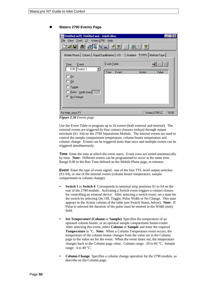
Figure 2.34 Events page
Use the Event Table to program up to 16 events (both external and internal). Theexternal events are triggered by four contact closures (relays) through outputterminals (S1–S4) on the 2790 Separations Module. The internal events are used tocontrol the sample compartment temperature, column heater temperature andcolumn change. Events can be triggered more than once and multiple events can betriggered simultaneously.
Time Enter the time at which the event starts. Event rows are sorted automaticallyby time. Note: Different events can be programmed to occur at the same time.Range 0.00 to the Run Time defined on the Mobile Phase page, in minutes.
Event Enter the type of event signal: one of the four TTL-level output switches(S1-S4), or one of the internal events (column heater temperature, samplecompartment or column change).
• Switch 1 to Switch 4 Corresponds to terminal strip positions S1 to S4 on therear of the 2790 module. Activating a Switch event triggers a contact closurefor controlling an external device. After selecting a switch event, set a state forthe switch by selecting On, Off, Toggle, Pulse Width or No Change. This stateappears in the Action column of the table (see Switch States, below). Note: IfPulse is selected the duration of the pulse must be entered in the Width (min)field.
• Set Temperature (Column or Sample) Specifies the temperature of anoptional column heater, or an optional sample compartment heater/cooler.After selecting this event, select Column or Sample and enter the requiredTemperature in °C. Note: When a Column Temperature event occurs, thetemperature of the column heater changes from the value set in the Columnpage to the value set for the event. When the event times out, the temperaturechanges back to the Column page value. Column range: 20 to 60 °C. Samplerange: 4 to 40 °C.
• Column Change Specifies a column change operation for the 2790 module, asdescribe on the Column page.
MassLynx NT Guide to Inlet Control
Page 51
Switch States
• On – Turns on a contact closure that triggers an external or internal event. Withthis function, the contact closure remains closed until an Off function is sent.
• Off – Turns off the contact closure for the event. With this function, the contactclosure is broken.
• Toggle – Changes the current state of the switch.
• Pulse – Transmits a single On/Off pulse. The contact closure is maintained forthe number of seconds that defined in the Value column. Range: 0.01 to 10.00sec.
• No Change – Leaves the switch in its current state.
Waters 2790 Event Table Operation
To add an event, type in a time, select an event from the drop down list box, select
an action and press the toolbar button. Up to 16 events can be programmed.
To delete a single event click with left mouse button on a time in the list and press
the toolbar button.
To delete all entries press the toolbar button. This button is only availablewhen there are entries in the timetable.
To modify an event select the required entry in the timetable. The values will thenbe displayed in the edit boxes and can be altered as appropriate. Once changed press
to re-enter the values into the timetable. If, however, you modify the timevalue such that it does not correspond to any existing entry in the timetable pressing
will result in a new entry being created in the timetable.

MassLynx NT Guide to Inlet Control
Page 52
n Waters 2790 Method Type Page
Figure 2.35 Method Type page
This page is used for creating normal, pre and post run methods. First create aNormal method and save the file, then create any pre or post run methods (savingthem under different names). These methods can then be defined in the Inlet Prerunand Inlet Postrun columns of the Sample List.
Method Type Select the type of method to create. The Parameters section willbe updated to show the parameters required for the selected method.
Normal Creates a normal method. No extra parameters need to be defined.
For all other method types see the Waters 2790 Menu, on page 53 for details of theparameters required.

MassLynx NT Guide to Inlet Control
Page 53
Waters 2790 Menu
Waters 2790 Wet Prime
Figure 2.36 Wet Prime dialog
Wet Prime A wet prime should be performed when changing the solvent in thesystem to flush out the previous solvent. The new solvent is pumped through thetubing and the Prime port of the Inject valve to waste.
Enter the Flow rate, Time and the Percentage of solvents to use then press thePrime button. Waters recommend that the wet prime is started using the solventwith the lowest viscosity to help purge air from the lines, especially if the in-linevacuum degasser is installed.
Note: If the solvent lines are dry then a dry prime must be performed before a wetprime. See the Waters 2790 Separation Module Operator’s Guide for moreinformation on performing a dry prime.
Waters 2790 Equilibrate
Figure 2.37 Equilibrate dialog
Equilibrate Equilibrates the system using the parameters defined on the MobilePhase page.
Enter the Time to equilibrate the system for and press OK. The time needed toequilibrate the system will depend on environmental and application-specificfactors.

MassLynx NT Guide to Inlet Control
Page 54
Waters 2790 Condition Column
Figure 2.38 Condition Column dialog
Condition Column Runs solvent through the column without injecting samplesor running the Events table. Solvent is delivered to the Column defined on theColumn page, using the Gradient Table defined on the Gradient page.
Enter the Time in minutes to condition the column for and press OK. Ensure thatthe time is equal to or greater than the Time of the last entry in the Gradient Table(defined on the Gradient page) plus the Re-equilibration Time (defined on the RapidEquilibration page).
Waters 2790 Wash Needle
Figure 2.39 Wash Needle dialog
Wash Needle Washes the inject port, and both the interior and exterior of theneedle with wash solvent, and then fills the needle with fresh solvent.
Enter the number of wash Cycles to perform and the Volume of wash solvent to usethen press OK. Waters recommend a volume of 600 µl.
Waters 2790 Refresh Syringe
Figure 2.40 Refresh Syringe dialog
Refresh Syringe Refills the syringe with fresh, degassed, purge solvent.
Enter the number of Cycles and the replacement Volume and press OK. Watersrecommend 12 Cycles and a volume of 600 µl.

MassLynx NT Guide to Inlet Control
Page 55
Waters 2790 Plate Generator
To display the Plate Generator dialog, select Plate Generator from the Waters2790menu.
Figure 2.41 Plate Generator
Plate Name The name of the plate that is currently being edited.
Rows The number of vials in a row and the distance between each center.
Columns The number of vials in a column and the distance between each center.
Offsets Allows alternate vial rows or columns to be offset. Note: Entering apositive value will shift even numbered rows to the right and negative values willshift even numbered rows to the left.
Vial Reference Allows the user to select the way that the vial rows and columnsare referenced, e.g. whether the rows are alphabetical or numerical.
Horizontal Sets the horizontal axis of the plate as either alphabetic (ABC) ornumeric (123), when using XY referencing.
Vertical Sets the vertical axis of the plate as either alphabetic (ABC) or numeric(123), when using XY referencing.

MassLynx NT Guide to Inlet Control
Page 56
Referencing This has three options
• XY which references the vials A1, B1 etc.
• Sequential Discontinuous which numbers the vials 1, 2, 3 across a row, left toright, and then starts the next row from the left again.
• Sequential Continuous which numbers the vials 1, 2, 3 across a row, left toright, then continues number the next row, right to left etc.
If the Waters 2790 autosampler is used with OpenLynx then the vial referencingmust be set to either sequential continuous or sequential discontinuous.
Priority Check the Horizontal First box if samples are to be acquired horizontallyacross the plate.
If Referencing = X,Y, Horizontal = Letter, Vertical = Number andHorizontal Priority is checked, this will result in samples being acquired in the orderA1, A2, A3. If the Horizontal Priority box is not checked samples will be acquiredin the order 1A, 1B, 1C etc.
If Referencing = sequential continuous or discontinuous and Horizontal Priority ischecked, this will result in samples being acquired from row 1 then row 2. If theHorizontal Priority box is not checked samples will be acquired from column 1 thencolumn 2 etc.
Plate Size The size of the plate to its outside edges.
Top Left Vial Offset The measurement to the center of the first vial from the topleft corner of the plate.
Vial The depth and diameter values are used for display only. They appear in thedescription for a single shot login on the OpenLynx Login screen.
n Creating and Deleting Waters 2790 Plates
To create a new plate, press the button. A new default plate is displayed,
change the Plate Name, enter the appropriate values and press the save buttonor select Save Plate from the Plate menu. New plates are saved to the MassLynxPlates directory.
To copy a plate, page through the list of saved plates using the and toolbar buttons. The Previous Plate and Next Plate options on the Plate menuperform the same operation. When the required plate is displayed change the Plate
Name, enter the appropriate values and press the save button or select SavePlate from the Plate menu. New plates are saved to the MassLynx Plates directory.
To delete a plate select the plate, by typing the name in the Plate Name box or by
paging through as above, and press the delete button or choose Delete Platefrom the Plate menu.
Note: All of the spacings and the vial section are stored in 0.1 mm units.
Note: When defining a custom plate for use with a multi-injector the plate isrequired to be compatible with the position of the 8 needles of the autosampler.

MassLynx NT Guide to Inlet Control
Page 57
• The Plate must have eight columns.
• The position of the vials should allow all eight needles to enter a separate vial.
• There should be no odd or even offsets for any of the vial positions.
Note: If the Plate currently selected on the Sample Configuration page is changedhere, then Reset Injector should be selected from the LC menu to resetcommunications.
Note: All of the spacings and the vial section are stored in 0.1 mm units.
Vial Referencing Examples
The following tables show four examples of vial referencing for a simplified 4 × 3vial plate.
1 2 3 4
A 1,A 2,A 3,A 4,A
B 1,B 2,B 3,B 4,B
C 1,C 2,C 3,C 4,C
Horizontal: 123
Vertical: ABC
Referencing: XY
Priority: Horizontal First Checked
1 2 3 4
A A,1 A,2 A,3 A,4
B B,1 B,2 B,3 B,4
C C,1 C,2 C,3 C,4
Horizontal: 123
Vertical: ABC
Referencing: XY
Priority: Horizontal First NOT Checked
1 2 3 4
A 1 2 3 4
B 5 6 7 8
C 9 10 11 12
Horizontal: N/A
Vertical: N/A
Referencing: Sequential Discontinuous
Priority: Horizontal First Checked
1 2 3 4
A 1 6 7 12
B 2 5 8 11
C 3 4 9 10
Horizontal: N/A
Vertical: N/A
Referencing: Sequential Continuous
Priority: Horizontal First NOT Checked
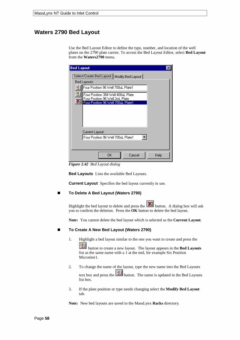
MassLynx NT Guide to Inlet Control
Page 58
Waters 2790 Bed Layout
Use the Bed Layout Editor to define the type, number, and location of the wellplates on the 2790 plate carrier. To access the Bed Layout Editor, select Bed Layoutfrom the Waters2790 menu.
Figure 2.42 Bed Layout dialog
Bed Layouts Lists the available Bed Layouts.
Current Layout Specifies the bed layout currently in use.
n To Delete A Bed Layout (Waters 2790)
Highlight the bed layout to delete and press the button. A dialog box will askyou to confirm the deletion. Press the OK button to delete the bed layout.
Note: You cannot delete the bed layout which is selected as the Current Layout.
n To Create A New Bed Layout (Waters 2790)
1. Highlight a bed layout similar to the one you want to create and press the
button to create a new layout. The layout appears in the Bed Layoutslist as the same name with a 1 at the end, for example Six PositionMicrotiter1.
2. To change the name of the layout, type the new name into the Bed Layouts
text box and press the button. The name is updated in the Bed Layoutslist box.
3. If the plate position or type needs changing select the Modify Bed Layouttab.
Note: New bed layouts are saved to the MassLynx Racks directory.

MassLynx NT Guide to Inlet Control
Page 59
n To Modify a Bed Layout (Waters 2790)
Use the Modify Bed Layout page to modify an existing bed layout. To access theModify Bed Layout page, click the Modify Bed Layout tab. The Modify BedLayout page shows a graphical representation of the selected bed layout. There arefour plate positions in the 2790.
Figure 2.43 Modify Bed Layout dialog
Click the plate that you want to change to display the Plate Position and Typedialog.
Figure 2.44 Plate Position and Type dialog
This dialog allows you to select a new plate from a list of possible options, andchange its actual position on the bed. Select the plate type you want to use in thebed layout, then click OK.
OpenLynx plate login If this box is checked and Use current MassLynxautosampler bed layout is checked in the OpenLynx Manager program, then theplate at this position can only be used for plate login on the OpenLynx Loginprogram.

MassLynx NT Guide to Inlet Control
Page 60
Waters CapLC System Status Pages
The System Status pages display information about the state of the machine beingcontrolled. These pages can be accessed within the Inlet Editor by selecting Status
from the View menu or by pressing the toolbar button.
n Waters CapLC Solvent Status Page
Figure 2.45 Solvent Status page
Indicators The Running, Pump On and Injector Cycle indicators at the left of thescreen give information on the current status of the LC system. The OK and ReadyIndicators become illuminated in red if the LC System has an error. Click on the redindicators to display more information on the cause of the malfunction.
Time This displays how long the method has been running.
Flow This displays the current flow rate as returned by the instrument.
Pressure This displays the current pressure in the instrument.
To the right of the Time, Flow and Pressure fields is a display of the solventpercentages at which the LC System is currently operating.
Column This displays the current temperature of the column.
Sample Temp This displays the current temperature of the sample.

MassLynx NT Guide to Inlet Control
Page 61
n Waters CapLC Valve Status Page
Figure 2.46 Valve Status page
Figure 2.47 Valve Status page
This page shows what position the Valves are currently set to, if installed.
See the Waters Cap LC Users’ Guide for details of the valves.

MassLynx NT Guide to Inlet Control
Page 62
n Waters CapLC PDA Status Page
Figure 2.48 PDA Status page
Current State This displays the current state of the PDA Detector.
Scan Number When acquiring diode array data this displays the number of scanscurrently acquired.
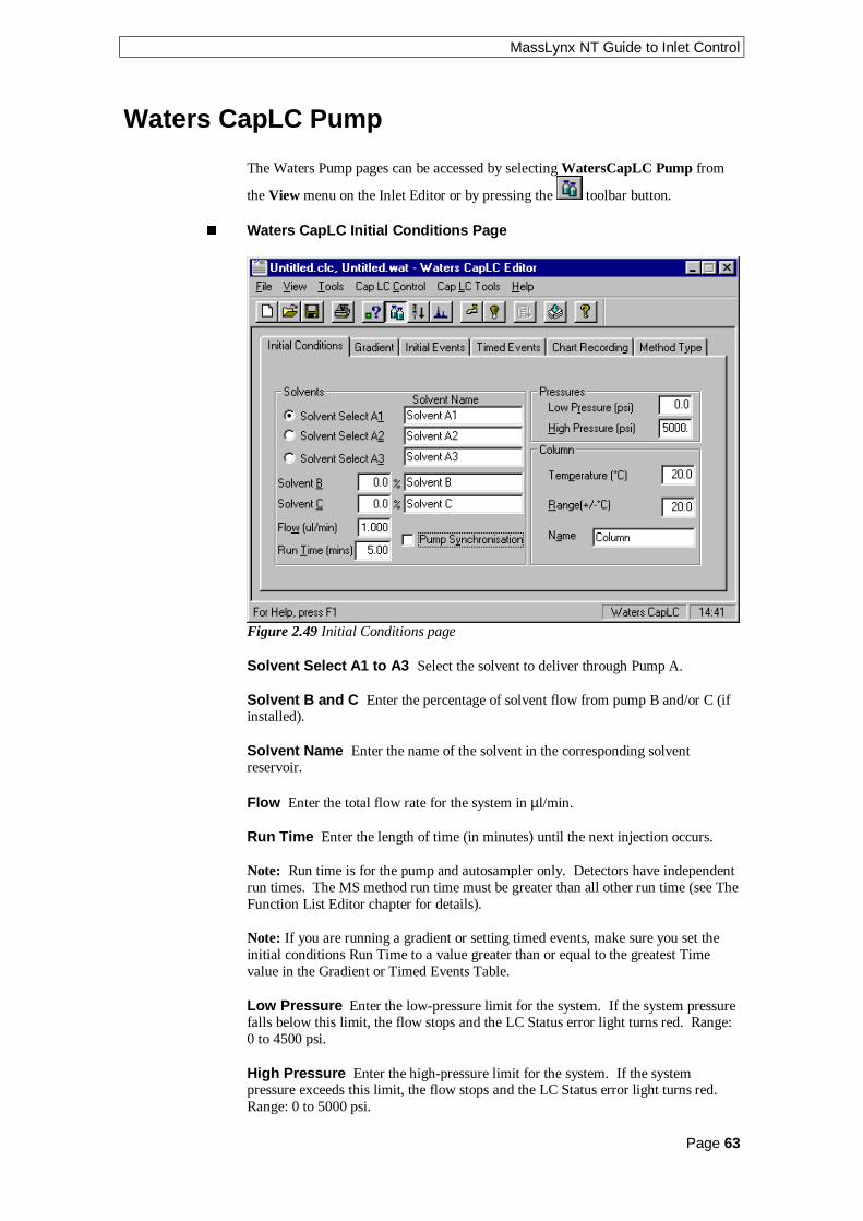
MassLynx NT Guide to Inlet Control
Page 63
Waters CapLC Pump
The Waters Pump pages can be accessed by selecting WatersCapLC Pump from
the View menu on the Inlet Editor or by pressing the toolbar button.
n Waters CapLC Initial Conditions Page
Figure 2.49 Initial Conditions page
Solvent Select A1 to A3 Select the solvent to deliver through Pump A.
Solvent B and C Enter the percentage of solvent flow from pump B and/or C (ifinstalled).
Solvent Name Enter the name of the solvent in the corresponding solventreservoir.
Flow Enter the total flow rate for the system in µl/min.
Run Time Enter the length of time (in minutes) until the next injection occurs.
Note: Run time is for the pump and autosampler only. Detectors have independentrun times. The MS method run time must be greater than all other run time (see TheFunction List Editor chapter for details).
Note: If you are running a gradient or setting timed events, make sure you set theinitial conditions Run Time to a value greater than or equal to the greatest Timevalue in the Gradient or Timed Events Table.
Low Pressure Enter the low-pressure limit for the system. If the system pressurefalls below this limit, the flow stops and the LC Status error light turns red. Range:0 to 4500 psi.
High Pressure Enter the high-pressure limit for the system. If the systempressure exceeds this limit, the flow stops and the LC Status error light turns red.Range: 0 to 5000 psi.

MassLynx NT Guide to Inlet Control
Page 64
Temperature Enter the target operating temperature for the optional columnheater. This value must be at least 5 °C above ambient. Range: 20 to 60 °C.Minimum setting: 5 °C above ambient.
Range Enter the maximum allowable temperature deviation from the value set forthe column heater temperature. If the column heater temperature deviates beyondthe specified range, the run stops and the LC Status error light turns red. Range:±0.0 to ±10.0 °C.
Name Enter the name of the installed column.
n Waters CapLC Gradient Page
Figure 2.50 Gradient page
Use the Gradient Table to define conditions for a gradient run. For each row in theGradient Table, define the percent composition of up to four solvents that are to bedelivered at the desired flow rate for the specified time. Enter the number of thegradient curve required. This defines how changes to solvent percentages and flowrates take place over the elapsed time of each gradient segment (the time that elapsesbetween the start time of one row and the start time of the next row).
Note: For an isocratic run, set the solvent percentages, run time and flow on theInitial Conditions page. Do not add any rows to the Gradient Table.
Waters CapLC Gradient Table Parameters
Time (mins) Specifies when the conditions (%A-%D, Flow, and Curve) for therow take effect. Make sure the Time for the first row is set to 0.00 to establishinitial conditions for the gradient run. Range for rows other than row 1: 0.01 to999.99 minutes.
B% and C% Specifies the percentage of solvent flow from each reservoir. Foreach row, the total of all solvents must equal 100%. Range: 0 to 100%.
Note: Percent flow for reservoir A is not displayed. Percent A is calculated as:100% - (B% + C%)
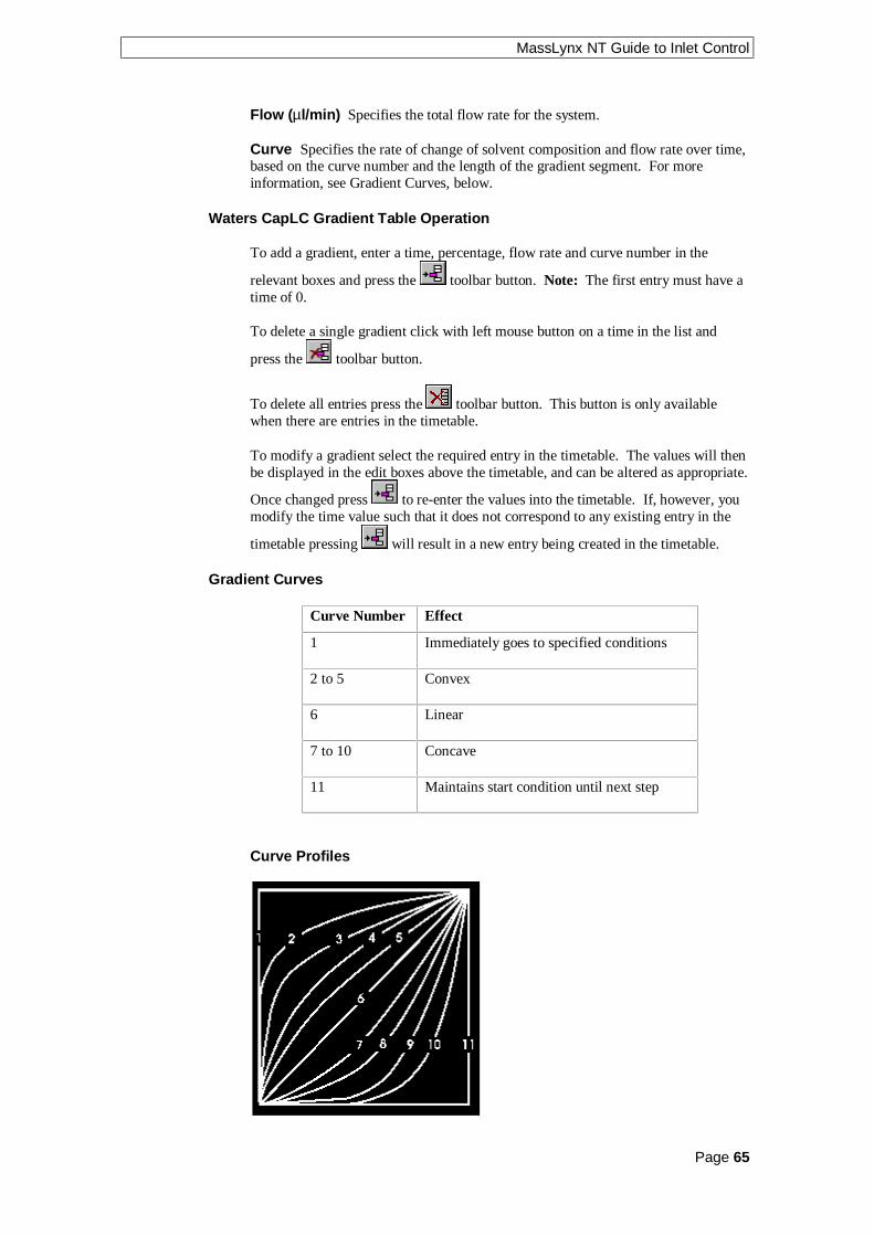
MassLynx NT Guide to Inlet Control
Page 65
Flow (µl/min) Specifies the total flow rate for the system.
Curve Specifies the rate of change of solvent composition and flow rate over time,based on the curve number and the length of the gradient segment. For moreinformation, see Gradient Curves, below.
Waters CapLC Gradient Table Operation
To add a gradient, enter a time, percentage, flow rate and curve number in the
relevant boxes and press the toolbar button. Note: The first entry must have atime of 0.
To delete a single gradient click with left mouse button on a time in the list and
press the toolbar button.
To delete all entries press the toolbar button. This button is only availablewhen there are entries in the timetable.
To modify a gradient select the required entry in the timetable. The values will thenbe displayed in the edit boxes above the timetable, and can be altered as appropriate.
Once changed press to re-enter the values into the timetable. If, however, youmodify the time value such that it does not correspond to any existing entry in the
timetable pressing will result in a new entry being created in the timetable.
Gradient Curves
Curve Number Effect
1 Immediately goes to specified conditions
2 to 5 Convex
6 Linear
7 to 10 Concave
11 Maintains start condition until next step
Curve Profiles

MassLynx NT Guide to Inlet Control
Page 66
n Waters CapLC Initial Events Page
Figure 2.51 Initial Events page
Use the Initial Events page to set the initial condition of the two contact-closureoutput switches, the initial position of the stream select valve, and the initial positionof the optional diverter valve.
Note: To change the settings of these switches and valves during a run, use theTimed Events Table.
Switch 1 and 2 Select the initial state of contact-closure Switch 1 and 2 from thedrop down list boxes.
Stream Select Select the initial state of the stream select valve (Position 1 or 2)from the drop down list box.
Diverter Select the initial position of the optional diverter valve (System or Vent)from the drop down list box.

MassLynx NT Guide to Inlet Control
Page 67
n Waters CapLC Timed Events Page
Figure 2.52 Timed Events page
Use the Event Table to program up to 16 events (both external and internal). Theexternal events are triggered by four contact closures (relays) through outputterminals (S1–S4) on the 2790 Separations Module. The internal events are used tocontrol the sample compartment temperature, column heater temperature, and toprime and flush the 2790 Separations Module. Events can be triggered more thanonce and multiple events can be triggered simultaneously.
Waters CapLC Event Table Parameters
Time Enter the time (after injection) at which the event starts. Event rows aresorted automatically by time. Note: Different events can be programmed to occurat the same time. Range: 0.00 to 999.99 min.
Event Select the type of event signal: one of the two contact-closure outputswitches (Switch1or Switch 2), or one of the internal events (Set temperature,Stream Select or Vent Valve). Choose from these event types to program up to 16events. Note: The same event can be programmed more than once. Availablechoices:
• Switch 1 and 2 Corresponds to terminal strip positions S1 and S2 on the rear ofthe unit. Activating a Switch event triggers a contact closure for controlling anexternal device. Select a switch event and a state for the switch (On, Off,Toggle, Pulse or No Change). This state appears in the Action column of thetable (see Switch States, below). Note: If Pulse is selected for a switch statethe duration of the pulse must be entered in the Width (min) field.

MassLynx NT Guide to Inlet Control
Page 68
• Set Temperature Specifies the temperature of an optional column heater. IfSet Temperature is selected for a switch state the temperature in (°C) must beentered in the Column Temperature field. Note: When this event occurs, thetemperature of the column heater changes from the value set on the InitialConditions page to the value set for the event. When the event times out, thetemperature returns to the value on the Initial Conditions page value.
• Stream Select (1 or 2) Specifies the position of the stream select valve.
• Vent Valve (System or Vent) Specifies the position of the vent valve.
Waters CapLC Switch States
• On – Turns on a contact closure that triggers an external or internal event. Withthis function, the contact closure remains closed until an Off function is sent.
• Off – Turns off the contact closure for the event. With this function, the contactclosure is broken.
• Toggle – Changes the current state of the switch.
• Pulse – Transmits a single On/Off pulse. The contact closure is maintained forthe time entered in the Width box. Range: 0.01 to 100.00 minutes.
• No Change – Leaves the switch in its current state.
Waters CapLC Event Table Operation
To add an event, enter a time, event, action and value in the relevant boxes and press
the toolbar button. Note the first entry must have a time of 0.
To delete a single event click with left mouse button on a time in the list and press
the toolbar button.
To delete all entries press the toolbar button. This button is only availablewhen there are entries in the timetable.
To modify an event select the required entry in the timetable. The values will thenbe displayed in the edit boxes, and can be altered as appropriate. Once changed
press to re-enter the values into the timetable. If, however, you modify thetime value such that it does not correspond to any existing entry in the timetable
pressing will result in a new entry being created in the timetable.

MassLynx NT Guide to Inlet Control
Page 69
n Waters CapLC Chart Recording Page
Figure 2.53 Chart Recording page
Use the Chart Recording page to select up to two analog signals to be output to anexternal device such as an integrator or strip-chart recorder. Select one of thefollowing the signals to output, from the drop down list box.
• None
• Flow
• Pressure
• Percent A, B, or C
• Column temperature
Note: To record a signal, you need to connect each external device to theappropriate Chart Out terminal pair on the rear of the unit. Refer to the WatersCapLC System Installation and Maintenance Guide for installation and specificationdetails.

MassLynx NT Guide to Inlet Control
Page 70
n Waters CapLC Method Type Page
Figure 2.54 Method Type page
Method Type Specifies the type of method to create. Select one of:
• Normal Method The Method Type used for standard injections. Ensure thatthe Method Type is set to Normal unless you are performing one of theprocedures listed below.
• Column Condition Method Runs solvent through the column withoutinjecting samples or running the Events table. Solvent is delivered using thegradient table specified in the Gradient page.
• Equilibrate Method Delivers solvents and maintains solvent parameters usingthe values defined on the Initial Conditions page.
• Wet Prime Replaces solvent in the tubing with fresh solvent from thereservoirs through the Prime port of the inject valve to waste. Use a Wet PrimeMethod when changing the solvents in the system. Check the boxes for thesolvent lines to prime, and the number of loop volumes to use.
Waters recommends starting the wet prime using the solvent with the lowestviscosity to help purge air from the lines, especially if the in-line vacuumdegasser is installed.
Note: If the solvent lines in the CapLC are dry, you must perform the dryprime procedure before performing a wet prime.

MassLynx NT Guide to Inlet Control
Page 71
Waters CapLC Autosampler
These pages are used to set parameters specific to the Autosampler, to access them
select WatersCapLC AutoSampler from the View menu or press the toolbarbutton.
n Waters CapLC AutoSampler Page
Figure 2.55 CapLC AutoSampler page
Draw Height Adjusts the depth of the needle tip to accommodate for sedimentedsamples. A value of 0 corresponds to the top of the plate carrier. Range: 0 to 40mm.
Draw Speed Select the draw rate of the syringe from the drop down list box. Thedifferent rates accommodate for samples of varying viscosity. The rate for eachselection is dependent on the size of the installed syringe. The table below showsthe draw rates for each selection.
Draw Rate for25 µl Syringe
Draw Rate for100 µl Syringe
Draw Rate for250 µl Syringe
Draw Ratefor 500 µlSyringe
Fast 94 µl/min 375 µl/min 940 µl/min 1875 µl/min
Normal 63 µl/min 250 µl/min 625 µl/min 1250 µl/min
Slow 32 µl/min 375 µl/min 315 µl/min 625 µl/min

MassLynx NT Guide to Inlet Control
Page 72
Injection Type Select one of the following injection types from the drop down listbox:
• Full Loop – The sample loop is completely filled.
• Partial Loop – The sample loop is partially filled with the volume defined inthe Sample List. The value in the Sample List must not exceed the Full Loopvolume.
• µl Pickup – The sample loop is filled with only the amount of sample to beinjected (resulting in no sample loss). Sample is transported into the loop bytransport liquid (mobile phase) from the transport vial.
• Manual – Specifies that the manual injector is used (the autosampler isdisabled). Switching the manual injector to the Inject position initiates anyprogrammed gradients and/or timed events.
Flush Volume Enter the volume (in microliters) of sample taken from a vialbefore the loop is filled with sample. This flushes out previous samples.
Head Space Pressure If this box is checked the prepuncturing needle will putapproximately 0.5 bar of pressure on the sample to stop formation of air or vapourbubbles. Enable this parameter only when using sample vials with air-tight caps.
Air Space Segment If this box is checked an air segment is added to the front ofthe flush volume to minimize dilution and bandspreading and reduce the amount offlush volume required. In Full and Partial Loop modes, the air segment is flushed towaste; in µl Pickup mode, the air segment is injected. Disable this parameter if theair segment causes problems in µl Pickup mode.
High Efficiency Mode If this box is checked the sample loop will be taken out ofthe flow stream after the sample has been flushed, but before the gradient frontreaches the injection valve.
Wash Volume Enter the volume (in microliters) of wash solvent used to clean theneedle and buffer tubing.
Sample Temperature Enter the target operating temperature for the optionalsample heater/cooler. Range: 4.0 to 40.0 °C.
Temperature Limit Enter the maximum allowable temperature deviation from thevalue set for the Sample Temperature. If the sample temperature deviates beyondthe specified range, the LC Status error light turns red and the run stops.Range: ±1.0 to ±20.0 °C.

MassLynx NT Guide to Inlet Control
Page 73
n Waters CapLC Mix Method Page
Figure 2.56 Mix Method page
Mix Delay Enter the delay time before mixing, in minutes. A value of 0corresponds to the top of the plate carrier. Range: 0 to 99.9 mins.
Mix Cycles Enter the number of times to perform the Mix operation.
Reagent Position 1 Enter the position of the first reagent to mix.
Volume Reagent 1 Enter the volume of reagent 1 to mix.
Reagent Position 2 Enter the position of the second reagent to mix.
Volume Reagent 2 Enter the volume of reagent 2 to mix.

MassLynx NT Guide to Inlet Control
Page 74
Waters CapLC Bed Layout
Use the Bed Layout Editor to define the type, number, and location of the wellplates on the CapLC plate loader. To access the Bed Layout Editor, select BedLayout from the Cap LC Tools menu.
Figure 2.57 Bed Layout Dialog
Bed Layouts Lists the available Bed Layouts.
Current Layout Specifies the bed layout currently in use.
n To Delete A Bed Layout (Waters CapLC)
Highlight the bed layout to delete and press the button. A dialog box will askyou to confirm the deletion. Press the OK button to delete the bed layout.
Note: You cannot delete the bed layout which is selected as the Current Layout.
n To Create A New Bed Layout (Waters CapLC)
1. Highlight a bed layout similar to the one you want to create and press the
button. The layout appears in the Bed Layouts list as the same namewith a 1 at the end, for example Six Position Microtiter1.
2. To change the name of the layout, type the new name into the Bed Layouts
text box and press the button. The name is updated in the Bed Layoutslist box.
3. If the plate position or type needs changing select the Modify Bed Layouttab.
Note: New bed layouts are saved to the MassLynx Racks directory.

MassLynx NT Guide to Inlet Control
Page 75
n To Modify a Bed Layout (Waters CapLC)
Use the Modify Bed Layout page to modify an existing bed layout. To access theModify Bed Layout page, click the Modify Bed Layout tab. The Modify BedLayout page shows a graphical representation of the selected bed layout.
Figure 2.58 Modify Bed Layout Dialog
Click on the plate that you want to change to display the Plate Position and Typedialog.
Figure 2.59 Plate Position and Type Dialog
This dialog allows you to select a new plate from a list of possible options, andchange its actual position on the bed. Select the plate type to use in the bed layout,then click OK.
OpenLynx plate login If this box is checked and Use current MassLynxautosampler bed layout is checked in the OpenLynx Manager program, then theplate at this position can only be used for plate login on the OpenLynx Loginprogram.

MassLynx NT Guide to Inlet Control
Page 76
n Other Bed Layout Options (Waters CapLC)
1. To append a new column, press the button.
2. To delete the current column press the button.
3. To insert a column, click on the column before which you want to insert and
press the button. Note: The column inserted will have the same numberof rows as the column highlighted.
4. Note: The number of rows in a column cannot be changed and so the button is greyed out.

MassLynx NT Guide to Inlet Control
Page 77
Waters CapLC Plate Generator
To display the Plate Generator dialog, select Plate Generator from theCap LC Tools menu.
Figure 2.60 Plate Generator
Plate Name The name of the plate that is currently being edited.
Rows The number of vials in a row and the distance between each center.
Columns The number of vials in a column and the distance between each center.
Offsets Allows alternate vial rows or columns to be offset. Note: Entering apositive value will shift even numbered rows to the right and negative values willshift even numbered rows to the left.
Vial Reference Allows the user to select the way that the vial rows and columnsare referenced, e.g. whether the rows are alphabetical or numerical.
Horizontal Sets the horizontal axis of the plate as either alphabetic (ABC) ornumeric (123), when using XY referencing. Default: numeric.
Vertical Sets the vertical axis of the plate as either alphabetic (ABC) or numeric(123), when using XY referencing. Default: alphabetic.
Referencing This has three options
• XY which references the vials A1, B1 etc.
• Sequential Discontinuous which numbers the vials 1, 2, 3 across a row, left toright, and then starts the next row from the left again.
• Sequential Continuous which numbers the vials 1, 2, 3 across a row, left toright, then continues number the next row, right to left etc.

MassLynx NT Guide to Inlet Control
Page 78
If the Waters CapLC autosampler is used with OpenLynx then the vial referencingmust be set to either sequential continuous or sequential discontinuous.
Priority Check the Horizontal First box if samples are to be acquired horizontallyacross the plate.
If Referencing = X,Y and Horizontal First is checked, then the horizontal value beread first when referencing a vial (1,A). If Horizontal First is not selected, then thevertical value be read first when referencing a vial (A,1). Default: Horizontal Firstselected.
If Referencing = Sequential Continuous or Discontinuous and Horizontal First ischecked, then vials will be numbered horizontally. This will result in samples beingacquired from row 1 then row 2. If Horizontal First is not checked, then vials willbe numbered vertically. This will result in samples being acquired from column 1then column 2 etc.
Default: Horizontal First selected.
Plate Size The size of the plate to its outside edges.
Top Left Vial Offset The measurement to the center of the first vial from the topleft corner of the plate.
Vial The depth and diameter values are used for display only. They appear in thedescription for a single shot login on the OpenLynx Login screen.
n Creating and Deleting Waters CapLC Plates
To create a new plate press the button. A new default plate is displayed, change
the Plate Name, enter the appropriate values and press the save button orselect Save Plate from the Plate menu. New plates are saved to the MassLynxPlates directory.
To copy a plate, page through the list of saved plates using the and toolbar buttons. The Previous Plate and Next Plate options on the Plate menuperform the same operation. When the required plate is displayed change the Plate
Name, enter the appropriate values and press the save button or select SavePlate from the Plate menu. New plates are saved to the MassLynx Plates directory.
To delete a plate select the plate, by typing the name in the Plate Name box or by
paging through as above, and press the delete button or choose Delete Platefrom the Plate menu.
Note: All of the spacings and the vial section are stored in 0.1 mm units.
Note: When defining a custom plate for use with a multi-injector the plate isrequired to be compatible with the position of the 8 needles of the autosampler.
• The Plate must have eight columns.
• The position of the vials should allow all eight needles to enter a separate vial.
• There should be no odd or even offsets for any of the vial positions.

MassLynx NT Guide to Inlet Control
Page 79
Note: If the Plate currently selected on the Sample Configuration page is changedhere, then Reset Injector should be selected from the LC menu to resetcommunications.
Note: All of the spacings and the vial section are stored in 0.1 mm units.
Vial Referencing Examples
The following tables show four examples of vial referencing for a simplified 4 × 3vial plate.
1 2 3 4
A 1,A 2,A 3,A 4,A
B 1,B 2,B 3,B 4,B
C 1,C 2,C 3,C 4,C
Horizontal: 123
Vertical: ABC
Referencing: XY
Priority: Horizontal First Checked
1 2 3 4
A A,1 A,2 A,3 A,4
B B,1 B,2 B,3 B,4
C C,1 C,2 C,3 C,4
Horizontal: 123
Vertical: ABC
Referencing: XY
Priority: Horizontal First NOT Checked
1 2 3 4
A 1 2 3 4
B 5 6 7 8
C 9 10 11 12
Horizontal: N/A
Vertical: N/A
Referencing: Sequential Discontinuous
Priority: Horizontal First Checked
1 2 3 4
A 1 6 7 12
B 2 5 8 11
C 3 4 9 10
Horizontal: N/A
Vertical: N/A
Referencing: Sequential Continuous
Priority: Horizontal First NOT Checked

MassLynx NT Guide to Inlet Control
Page 80
Waters CapLC Plate Loader
To display the Plate Loader dialog, select Plate Loader from the Cap LC Toolsmenu.
Figure 2.61 Plate Loader
The Plate Loader dialog is used when a plate needs to be changed.

MassLynx NT Guide to Inlet Control
Page 81
Waters CapLC PDA Detector
This page is used to set parameters specific to the UV detector, to access it select
WatersCapLC PDA Detector from the View menu or press the toolbar button.
Figure 2.62 CapLC PDA Detector Configuration page
Start Wavelength Enter the wavelength at which to start acquiring data.
Range (with Resolution set to 1.2): 190.0 nm to 800.0 nm. Range (at all otherResolution settings): 190.0 + (Resolution/2) to 800.0 – (Resolution/2). Default: 200nm.
End Wavelength Enter the wavelength at which to stop acquiring data.
Range with Resolution set to 1.2: Start Wavelength to 800.0 nm. Range at all otherResolution settings: Start Wavelength + Resolution to 800.0 nm – Resolution/2.
Resolution Enter the number of diodes to be averaged together as a single spectraldata point. To differentiate closely related spectra and obtain greater spectralresolution, use a small resolution number. Be aware, however, that a smallresolution value generates more data points and therefore requires more disk spacethan a large resolution value. Find a resolution value just small enough to identifyspectral features. Range: 1.2 to 24.0 nm in multiples of 1.2.
Sampling Rate Select the acquisition rate in spectra per second from the dropdown list box. For good integration and quantitation, acquire 15 to 20 spectra acrossa peak.
Auto Exposure Check this box to enable the detector optics to calculate theoptimum exposure time needed to recharge the diodes based on the lamp energy, thelamp spectrum and the selected wavelength range.
Tip: Enable Auto Exposure for most routine analyses.

MassLynx NT Guide to Inlet Control
Page 82
Interpolate Check this box to instruct the detector to ignore the signal from thephotodiode at 656 nm and to interpolate a value from the adjacent diodes. Thisprevents over-saturation at 656 nm (Balmer line for deuterium).
If this box is not checked the detector reports the signal from the photodiode at 656nm. Disable this parameter only if you are working with compounds that absorb inthe 656 nm range.
Note: If this parameter is unchecked, the deuterium lamp high emission line at 656nm may cause spectral artifacts and autoexposure errors.
Exposure Time Enter the length of time in milliseconds that the photodiodes areexposed to light before they are read. This parameter is not accessible if AutoExposure is checked. Range: 11.00 to 500.00 ms.
Stop Time Enter the time, in minutes after injection, when the PDA will stopscanning. This value is independent of the instrument method run time.
Filter Response Enter the response time (in seconds) for filtering acquired data.The filter is an enhanced rolling average filter applied to absorbance data from thePDA detector before the data is sent to the MassLynx software. The filter reduceshigh-frequency noise across the entire wavelength range specified for theacquisition. High values decrease peak response. Range: 0 to 3.
Save to Disk Check this box to save the Photo Diode Array data to the rawdatafile. If this data is not required for further processing then uncheck the box, thedata is not saved to disk thus reducing the size of the file.
n Waters CapLC Channel Detector Configuration Pages
The Channel 1 and Channel 2 pages contain the same information. Select the pagerelevant to the channel required, by clicking on the tab.
Figure 2.63 Channel 1 Detector Configuration page

MassLynx NT Guide to Inlet Control
Page 83
Output Mode Select one of:
• Off – no analog output signal.
• Absorbance – Output represents absorbance at the wavelength specified by theWavelength parameter (see below).
Note: Ratio Denominator Wavelength and Threshold parameters are notaccessible when Absorbance mode is selected.
• Ratio – Output represents the ratio of absorbances at two wavelengths. Thenumerator wavelength is specified by the Wavelength parameter, and thedenominator wavelength is specified by the Ratio Denominator Wavelengthparameter (see below).
Wavelength Enter the output wavelength. In Ratio mode, the absorbance at theWavelength is used to calculate ratio in the formula:
Ratio = Absorbance at Wavelength/Absorbance at Ratio DenominatorWavelength
Wavelength must be within the wavelength range specified by the Start Wavelengthand End Wavelength parameters on the PDA page.
Range when Resolution is set to 1.2: Start Wavelength to End Wavelength. Rangeat all other Resolution settings: Start Wavelength + (Bandwidth/2) to EndWavelength – (Bandwidth/2).
Ratio Denominator Wavelength Enter the denominator wavelength (innanometers) for the analog output channel. Ratio Denominator Wavelength must bewithin the wavelength range specified by the Start Wavelength and End Wavelengthparameters in the 996 PDA page.
Bandwidth Enter the spectral bandwidth of the analog output channel. Range:1.2 to 24.0 nm in multiples of 1.2.
Filter Type Select the filter type (Hamming or Single Pole) from the drop downlist box for use on the analog output channel. The Hamming filter is designed tocreate the same degree of peak-height degradation as the Single Pole filter for thesame response time, but enhances filtering of high-frequency noise.
Filter Response Enter the response time in seconds for the Filter Type specifiedabove. Range: 0 to 5 seconds.
Offset If required enter an offset to the analog output channel. Range: –0.2 to 2.0AU.
Threshold Enter a threshold above which the ratio (Wavelength / RatioDenominator Wavelength) must be to be valid data. The range is –0.1 to 2.0 AU.
Note: If no ratio is plotted (one or both channels are below the current Threshold),enter a lower Threshold value.

MassLynx NT Guide to Inlet Control
Page 84
Waters 515 and 1525 Pumps
The Waters 515 and 1525 Pump pages can be accessed by selecting Waters 515Pump or Waters 1525 Pump from the View menu on the Inlet Editor or by
pressing the toolbar button.
n Waters 515/1525 Initial Conditions Page
Figure 2.64 Initial Conditions page
Solvent A Enter the name of the solvent that will be delivered through Pump A.
Solvent B Enter the name of the solvent that will be delivered through Pump Band enter the percentage of the solvent flow from Pump B.
Flow (ml/min) Enter the total flow rate for the solvent delivery system.Range: 1 to 10 ml/min.
Run Time Enter the time in minutes that the method will run, from the point ofinjection.
Note: If you are running a gradient or setting timed events, make sure the RunTime value is greater than, or equal to the greatest Time value, specified on theGradient or Timed Events pages.
Low Pressure Enter the low pressure limit for the system. If the pressure fallsbelow this limit, the solvent flow will stop and the LC status light will turn red.
High Pressure Enter the high pressure limit for the system. If the pressureexceeds this limit, the solvent flow will stop and the LC status light will turn red.

MassLynx NT Guide to Inlet Control
Page 85
Waters 515
If you selected a Waters 515 Pump, the Auxiliary Pump Solvent options aredisplayed:
Flow (ml/min) Enter the total flow rate for the auxiliary solvent delivery system.Range: 1 to 10 ml/min.
Name Enter the name of the solvent that will be delivered through the auxiliarypump.
n Waters 515/1525 Gradient Page
Figure 2.65 Gradient page
Use the Gradient Table to define conditions for a gradient run. For each row in theGradient Table, you need to define the % composition of up to two solvents that areto be delivered at the desired flow rate for the specified Time.
Note: For an isocratic run, set the solvent percentages, run time and flow, on theInitial Conditions page. Do not add any rows to the Gradient Table.
To add a gradient, enter a time and percentage in the relevant boxes and press the
toolbar button. Note: The first entry must have a time of 0.
To delete a single gradient, click with left mouse button on a time in the list and
press the toolbar button.
To delete all entries press the toolbar button. This button is only availablewhen there are entries in the timetable.

MassLynx NT Guide to Inlet Control
Page 86
To modify a gradient, select the required entry in the timetable. The values will thenbe displayed in the edit boxes to the left of the timetable, and can be altered as
appropriate. Once changed press to re-enter the values into the timetable. If,however, you modify the time value such that it does not correspond to any existing
entry in the timetable pressing will result in a new entry being created in thetimetable.
Flow Enter the flow rate for the solvent delivery system.
Curve Enter the number of the gradient curve required. This sets the rate at whichthe solvent is to change to the new proportions and/or flow rates. See the WatersOperator’s Guide for a list of values.
n Waters 515/1525 Initial Events Page
Figure 2.66 Initial Events page
The external events are triggered by four contact closures (relays) through outputterminals, which are located at the back of the instrument.
Waters 515
Relays 1 and 2 From the drop down list box, select ON or Off to activate ordeactivate the relay.
Events 1 to 4 From the drop down list box, select ON or Off to activate ordeactivate the event.
Waters 1525
Relays 1 to 4 From the drop down list box, select ON or Off to activate ordeactivate the relay.

MassLynx NT Guide to Inlet Control
Page 87
n Waters 515/1525 Timed Events Page
Figure 2.67 Timed Events page
Use the Event Table to program up to 16 events (both external and internal). Eventscan be triggered more than once and multiple events can be triggeredsimultaneously.
Time Enter the time (after injection) at which the event starts. Event rows aresorted automatically by time. Note: Different events can be programmed to occurat the same time. Range: 0.00 to 999.99 min.
Event Select an Event or Relay from the drop down list box.
Switch States
On Turns on a contact closure that triggers an external or internal event. With thisfunction, the contact closure remains closed until an Off function is sent.
Off Turns off the contact closure for the event. With this function, the contactclosure is broken.

MassLynx NT Guide to Inlet Control
Page 88
Event Table Operation
To add an event, enter a time, event, action and value in the relevant boxes and press
the toolbar button. Note the first entry must have a time of 0.
To delete a single event, click with left mouse button on a time in the list and press
the toolbar button.
To delete all entries press the toolbar button. This button is only availablewhen there are entries in the timetable.
To modify an event, select the required entry in the timetable. The values will thenbe displayed in the edit boxes, and can be altered as appropriate. Once changed
press to re-enter the values into the timetable. If, however, you modify thetime value such that it does not correspond to any existing entry in the timetable
pressing will result in a new entry being created in the timetable.
n Waters 515/1525 Method Type Page
Figure 2.68 Method Type page
Method Type Specifies the type of method to create.
Normal Method The Method Type used for standard injections. Ensure that theMethod Type is set to Normal unless you are performing one of the procedureslisted below.
Column Condition Method Runs solvent through the column without injectingsamples or running the Events table. Solvent is delivered using the gradient tablespecified in the Gradient page.
Equilibrate Method Delivers solvents and maintains solvent parameters using thevalues defined on the Initial Conditions page.
Run Event Table Check this box to run the table of timed events during themethod. This option is only active if the Normal or Column Condition Methodsare selected.

MassLynx NT Guide to Inlet Control
Page 89
Notes................................................................................................................................................................
................................................................................................................................................................
................................................................................................................................................................
................................................................................................................................................................
................................................................................................................................................................
................................................................................................................................................................
................................................................................................................................................................
................................................................................................................................................................
................................................................................................................................................................
................................................................................................................................................................
................................................................................................................................................................
................................................................................................................................................................
................................................................................................................................................................
................................................................................................................................................................
................................................................................................................................................................
................................................................................................................................................................
................................................................................................................................................................
................................................................................................................................................................
................................................................................................................................................................
................................................................................................................................................................
................................................................................................................................................................
................................................................................................................................................................
................................................................................................................................................................
................................................................................................................................................................
................................................................................................................................................................
................................................................................................................................................................
................................................................................................................................................................

MassLynx NT Guide to Inlet Control
Page 90
Notes................................................................................................................................................................
................................................................................................................................................................
................................................................................................................................................................
................................................................................................................................................................
................................................................................................................................................................
................................................................................................................................................................
................................................................................................................................................................
................................................................................................................................................................
................................................................................................................................................................
................................................................................................................................................................
................................................................................................................................................................
................................................................................................................................................................
................................................................................................................................................................
................................................................................................................................................................
................................................................................................................................................................
................................................................................................................................................................
................................................................................................................................................................
................................................................................................................................................................
................................................................................................................................................................
................................................................................................................................................................
................................................................................................................................................................
................................................................................................................................................................
................................................................................................................................................................
................................................................................................................................................................
................................................................................................................................................................
................................................................................................................................................................
................................................................................................................................................................

MassLynx NT Guide to Inlet Control
Page 91
CE InstrumentsChapter 3
CE Instruments GC8000 Gas Chromatograph
On a CE Instruments GC8000, MassLynx can control the oven temperature, theinjector zone temperatures, the valve times, the dump valve and 4 external eventtimes.
n To change GC Parameters
1. Choose Set up Inlet from the Acquisition Control Panel Instrument menu.
- or -
Double click on the picture of the GC on the Acquisition Control Panel todisplay the GC8000 inlet editor shown below.
2. Make any changes to the parameters. Note: The oven temperature ramp canbe modified either by using the keyboard to enter times, temperatures andrates, or by dragging the small red handles on the graph with the mouse.
3. Save the method using either Save or Save As from the File menu.
Figure 3.1 GC8000 Inlet Editor
The time and temperature range of the oven temperature ramp can be controlled
using the buttons displayed to the right of the ramp. Clicking on will increase
the range shown on the time axis. Clicking on will increase the range shown on
the temperature axis. Clicking on alters the display ranges so that the oventemperature display fills the graph.

MassLynx NT Guide to Inlet Control
Page 92
A full description of all the parameters in this editor is given in the GC8000 SeriesInstruction Manual.
n Changing Valve Event Times
Timed events such as Purge and Split times can be included in the GC method.These are programmed using the GC 8000 Valve Control editor shown below.
Figure 3.2 GC8000 Valve Editor
To display this dialog select Valve Timetable from the Valves menu. The eventsparameters are stored to disk when the GC parameters are saved, not when thisdialog is closed so ensure that parameters are saved before starting an acquisition.
n To control the GC8000 DPFC option
MassLynx can control the DPFC option on the GC8000 for Quattro II and Platforminstruments.
1. Select Configuration from the GC8000 editor DPFC menu.
Figure 3.3 DPFC Configuration dialog
2. Configure the left and right channels as required. Each channel can be set toflow, pressure or off.
3. Select Left Channel or Right Channel from the GC8000 editor DPFC menuto load either the Flow Ramp or Pressure Ramp Editor depending how thechannel is configured.

MassLynx NT Guide to Inlet Control
Page 93
Figure 3.4 DPFC Flow Ramp Editor
Figure 3.5 DPFC Pressure Ramp Editor
4. Make any changes required and press OK to exit and save changes.
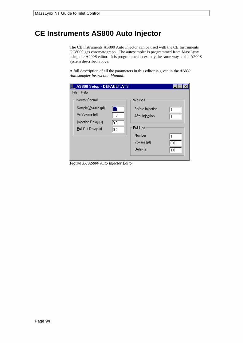
MassLynx NT Guide to Inlet Control
Page 94
CE Instruments AS800 Auto Injector
The CE Instruments AS800 Auto Injector can be used with the CE InstrumentsGC8000 gas chromatograph. The autosampler is programmed from MassLynxusing the A200S editor. It is programmed in exactly the same way as the A200Ssystem described above.
A full description of all the parameters in this editor is given in the AS800Autosampler Instruction Manual.
Figure 3.6 AS800 Auto Injector Editor

MassLynx NT Guide to Inlet Control
Page 95
Notes................................................................................................................................................................
................................................................................................................................................................
................................................................................................................................................................
................................................................................................................................................................
................................................................................................................................................................
................................................................................................................................................................
................................................................................................................................................................
................................................................................................................................................................
................................................................................................................................................................
................................................................................................................................................................
................................................................................................................................................................
................................................................................................................................................................
................................................................................................................................................................
................................................................................................................................................................
................................................................................................................................................................
................................................................................................................................................................
................................................................................................................................................................
................................................................................................................................................................
................................................................................................................................................................
................................................................................................................................................................
................................................................................................................................................................
................................................................................................................................................................
................................................................................................................................................................
................................................................................................................................................................
................................................................................................................................................................
................................................................................................................................................................
................................................................................................................................................................

MassLynx NT Guide to Inlet Control
Page 96
Notes................................................................................................................................................................
................................................................................................................................................................
................................................................................................................................................................
................................................................................................................................................................
................................................................................................................................................................
................................................................................................................................................................
................................................................................................................................................................
................................................................................................................................................................
................................................................................................................................................................
................................................................................................................................................................
................................................................................................................................................................
................................................................................................................................................................
................................................................................................................................................................
................................................................................................................................................................
................................................................................................................................................................
................................................................................................................................................................
................................................................................................................................................................
................................................................................................................................................................
................................................................................................................................................................
................................................................................................................................................................
................................................................................................................................................................
................................................................................................................................................................
................................................................................................................................................................
................................................................................................................................................................
................................................................................................................................................................
................................................................................................................................................................
................................................................................................................................................................
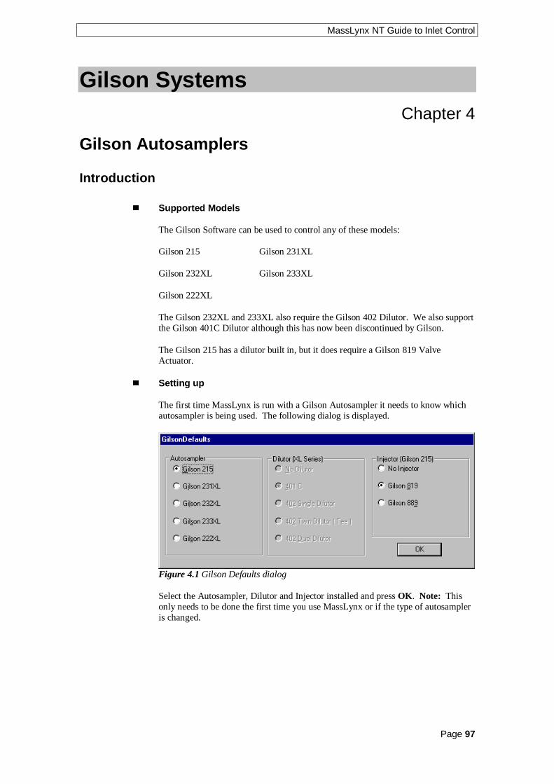
MassLynx NT Guide to Inlet Control
Page 97
Gilson SystemsChapter 4
Gilson Autosamplers
Introduction
n Supported Models
The Gilson Software can be used to control any of these models:
Gilson 215 Gilson 231XL
Gilson 232XL Gilson 233XL
Gilson 222XL
The Gilson 232XL and 233XL also require the Gilson 402 Dilutor. We also supportthe Gilson 401C Dilutor although this has now been discontinued by Gilson.
The Gilson 215 has a dilutor built in, but it does require a Gilson 819 ValveActuator.
n Setting up
The first time MassLynx is run with a Gilson Autosampler it needs to know whichautosampler is being used. The following dialog is displayed.
Figure 4.1 Gilson Defaults dialog
Select the Autosampler, Dilutor and Injector installed and press OK. Note: Thisonly needs to be done the first time you use MassLynx or if the type of autosampleris changed.

MassLynx NT Guide to Inlet Control
Page 98
The Gilson Toolbar
The Gilson toolbar has three extra buttons on it, which are:
Click To
Prime the Dilutor.
Generate Custom Racks.
Gilson Configuration Pages
These pages contain information that is used to configure the autosampler. To
access them press the button or select Gilson AutoSampler from theInlet Editor View menu.
n The Gilson Task List
This page is used to build up a set of tasks into a method that is then used to performthe injection. The available tasks are contained in the Task drop down list box andthe parameters displayed will depend on which task is selected.
Figure 4.2 Task List page
MassLynx NT Guide to Inlet Control
Page 99
n Adding and Deleting Tasks (Gilson)
To add a task select it from the Task drop down list box, set the parameters and
press the add button. The task will be added to the end of the list.
To delete a single task, select it from the Task List and press the delete button.
To clear all of the tasks in the Task List press the clear all button.
n Modifying Tasks (Gilson)
To modify a task select it from the Task List, change the required parameters and
press the add button.
n Moving and Copying Tasks (Gilson)
To move a task, select it with the mouse, hold the mouse button down and move thetask to the required position.
To copy a task follow the procedure for moving tasks but hold the CTRL key downwhen moving the mouse.
n The Individual Tasks (Gilson)
This section contains tables listing the individual parameters for each task.
Inject Partial Loop
This is the main task that is used to inject. The Injection volume is entered in thesample list.
Parameter DescriptionAspiration Flow Rate This is the flow rate at which the sample is drawn into
the needle.
Displacement Flow This is the flow rate at which the sample is injected intothe loop.
Valve Flush Volume. This is the volume of solvent that is flushed through thevalve after the injection. It is displaced at theDisplacement flow.
Table 4.1 Inject partial loop parameters

MassLynx NT Guide to Inlet Control
Page 100
Detailed below is a list of the steps that occur during the inject partial loop task.
Steps:
1. Move to vial
2. Aspirate air gap if required
3. Move Zarm down to vial depth
4. Aspirate injection volume + injection flush volume
5. Move Zarm back to travel height
6. Move to injection port
7. Move to injection depth
8. Switch valve to inject position
9. Dispense injection flush volume
10. Switch valve to load
11. Dispense injection volume
12. Switch valve to inject
13. Pulse output contact
14. Dispense air gap
15. Rinse valve if a flush volume has been specified
Note: The Left and right valve become enabled when using a Gilson 233XL.
Rinse Injection Port
This task is used to rinse the injection port with solvent from the reservoir.
Parameter DescriptionRinsing Volume This is the volume of solvent that is to be rinsed through
the needle.
Displacement Flow This is the flow rate at which the solvent is injected intothe valve.
Table 4.2 Rinse Injection Port parameters
Note: The Left and right valve become enabled when using a Gilson 233XL.

MassLynx NT Guide to Inlet Control
Page 101
Rinse Inside Needle
This task is used to rinse the inside of the needle with solvent from the reservoir.
Parameter DescriptionRinsing Volume This is the volume of solvent that is to be rinsed through
the needle.
Displacement Flow This is the flow rate at which the solvent is rinsedthrough the needle.
Rinse Station This is the rinse station at which you would like therinse to take place. If this is set to auto then the nearestrinse station is chosen.
Table 4.3 Rinse Inside Needle parameters
Rinse Outside Needle
This task is used to rinse the outside of the needle with solvent from the reservoir.
Parameter DescriptionRinsing Volume This is the volume of solvent that is to be rinsed through
the needle.
Displacement Flow This is the flow rate at which the solvent is rinsedthrough the needle.
Depth This is set to the depth that the needle should move tofor rinsing.
Rinse Station This is the rinse station at which you would like therinse to take place. If this is set to auto then the nearestrinse station is chosen.
Table 4.4 Rinse Outside Needle parameters
Because this task dispenses the solvent through the inside of the needle it also actsas a rinse inside needle.
Note: Rinsing the Outside of the needle is not available on the Gilson215
Set Electrical Contact
This task is used when you would like to set one of the output contacts.
Parameter DescriptionContact Number This is the number of the contact that you would like to
set.
State This is the state that you want to set. Open, Close orPulse.
Table 4.5 Set Electrical Contact parameters

MassLynx NT Guide to Inlet Control
Page 102
Wait For Contact
This task is used when you need to wait for a contact state.
Parameter DescriptionContact Number This is the number of the contact that you would like to
set.
State This is the state that you want to set. Open, Close orPulse.
Table 4.6 Wait For contact parameters
Wait For Time
This task is used if you need the machine to wait for a specified time.
Parameter DescriptionTime The time that you wish to wait for.
Table 4.7 Wait For Time parameters
n Gilson Dilutor Configuration Page
This page is used to set parameters specific to the Dilutor.
Figure 4.3 Dilutor Configuration page
Syringe Volumes The size of the currently installed Left and Right syringes.
Reservoir Aspiration Flow This is the flow rate at which solvent is drawn fromthe reservoir (the default value is usually sufficient).
Prime Displacement Flow This is the flow rate at which the solvent is displacedduring the prime dilutor (the default value is usually sufficient).

MassLynx NT Guide to Inlet Control
Page 103
Inlet Tubing volume This is the volume of the tubing between the injection portand the rheodyne valve. It is the volume of air used to push the sample through intothe injection loop.
Sample Flush volume This is the amount of sample that is drawn with theinjection valve. This amount is then injected before the valve switches to fill thetube between the valve and the injection port. Any excess will go to waste.
Note: When using the Gilson 402 Dilutor, the Left and Right syringe radio buttonsare enabled allowing you to use the left and right syringes. This is not yet available.
n Gilson Sampler Configuration Page
This page is used to set parameters specific to the Sampler.
Figure 4.4 Sampler Configuration page
Current Layout Select the required layout from the drop down list box. A pictureof the selected bed layout is displayed below the name.
Rinse Stations Present Check the boxes if the rinse stations are present. Leftand right are as you look at the machine.
Note: When using the Gilson 215 the right rinse station will be disabled.

MassLynx NT Guide to Inlet Control
Page 104
n Gilson Multi-Injector Parameters Page
This page is used to set parameters specific to the Gilson Multi-Injector System.This is an autosampler device that injects up to 8 samples simultaneously. TheMulti-Injector itself consists of a Gilson 215 autosampler in conjunction with aGilson 889 multi-valve injector. The device has eight needles connected to the robotarm and a syringe for each needle. The geometry of the autosampler is designed sothat the 8 needles will enter 8 separate wells of a microtitre plate. The 8 samples arepicked up at the same time and then deposited into 8 separate injection loops. Thevalves connected to these loops can then be controlled individually so that each ofthe samples can be sent to the mass spectrometer at any specified times.
To enable these parameters the following configuration must be defined.
1. Select Advanced Configuration from the Gilson Sampler menu.
2. On the Hardware tab select Gilson 215 from the Sampler drop down list box.
3. On the Hardware tab select Gilson 889 from the Valve drop down list box.
4. On the Hardware tab select All samples to same file from the Multi-InjectorMode drop down list box.
5. On the Hardware tab check the Enable Inject Ahead box.
6. Press OK.
Figure 4.5 Multi-Injector Parameters page
Scan Time per Sample This defines the analysis time spent on each sample.
Delay This is the time for the sample to travel from the injection port to the massspectrometer.
Length This is the amount (in seconds) of the chromatogram that is used to createthe data files for each of the samples.
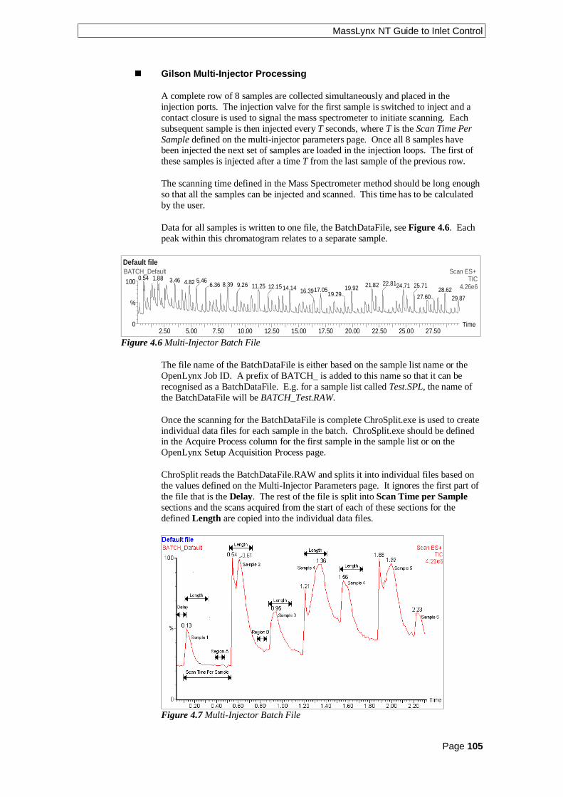
MassLynx NT Guide to Inlet Control
Page 105
n Gilson Multi-Injector Processing
A complete row of 8 samples are collected simultaneously and placed in theinjection ports. The injection valve for the first sample is switched to inject and acontact closure is used to signal the mass spectrometer to initiate scanning. Eachsubsequent sample is then injected every T seconds, where T is the Scan Time PerSample defined on the multi-injector parameters page. Once all 8 samples havebeen injected the next set of samples are loaded in the injection loops. The first ofthese samples is injected after a time T from the last sample of the previous row.
The scanning time defined in the Mass Spectrometer method should be long enoughso that all the samples can be injected and scanned. This time has to be calculatedby the user.
Data for all samples is written to one file, the BatchDataFile, see Figure 4.6. Eachpeak within this chromatogram relates to a separate sample.
Default file
2.50 5.00 7.50 10.00 12.50 15.00 17.50 20.00 22.50 25.00 27.50Time0
100
%
BATCH_Default Scan ES+ TIC
4.26e60.54 1.88 3.46 4.82 5.46
8.396.36 21.8211.259.26 19.9214.1412.15 17.0516.39 19.2924.7122.81 25.71
28.6227.60 29.87
Figure 4.6 Multi-Injector Batch File
The file name of the BatchDataFile is either based on the sample list name or theOpenLynx Job ID. A prefix of BATCH_ is added to this name so that it can berecognised as a BatchDataFile. E.g. for a sample list called Test.SPL, the name ofthe BatchDataFile will be BATCH_Test.RAW.
Once the scanning for the BatchDataFile is complete ChroSplit.exe is used to createindividual data files for each sample in the batch. ChroSplit.exe should be definedin the Acquire Process column for the first sample in the sample list or on theOpenLynx Setup Acquisition Process page.
ChroSplit reads the BatchDataFile.RAW and splits it into individual files based onthe values defined on the Multi-Injector Parameters page. It ignores the first part ofthe file that is the Delay. The rest of the file is split into Scan Time per Samplesections and the scans acquired from the start of each of these sections for thedefined Length are copied into the individual data files.
Figure 4.7 Multi-Injector Batch File

MassLynx NT Guide to Inlet Control
Page 106
Some of the scans between any two samples will contain some mixing of samples(e.g. Region B in Figure 4.7 ) or not contain data relating to either sample (e.g.Region A in Figure 4.7 ). The data in these regions is not required, therefore onlydata in Length region is copied.
Once all data files have been created by ChroSplit the acquisition will proceed withany processing defined in the Process column for the first sample in the batch. Forall subsequent samples in the batch no data is acquired only the processes areinitiated.
ChroSplit currently writes two data files per sample. The first has a re-normalisedretention time so that the retention time of the first scan for each sample is set to 0.This allows analysis of the masses to proceed via loop injection, which simplysearches for masses contained within the scan at a user-defined retention time. Theother file written retains its original retention time and is used to assess the accuracyof the ChroSplit procedure. This second data file has the prefix “CHECK_” addedto the .RAW file name.
Figure 4.8 The results of using ChroSpilt.exe. Upper shows the Batch file, middle there-normalised files and lower the check files

MassLynx NT Guide to Inlet Control
Page 107
n Problems with ChroSplit
If ChroSplit fails to copy the BatchDataFile scans correctly (due to an incorrectdelay being defined or experimental faults, e.g. a change in pumping speed) then thedelay and length parameters can be changed and the BatchDataFile reprocessed.
To do this the values in the timefile.tfl need to be changed. This file contains thetime each sample reaches the mass spectrometer and is stored in theBatchDataFile.RAW directory. Also written to this file are the sample number,sample location for each sample and the multi-injector length and delay parameters.
[timefile]
MasterRawFile=Batch_xxxxx
Delay=4.5
Length=15
[Sample] [Location] [Injection Time] [Sample ID]
1 "1,A" 0.195375 "Not used"
2 "1,B" 26.472376 "Not used"
3 "1,C" 46.591373 "Not used"
4 "1,D" 66.700378 "Not used"Figure 4.9 Example timefile.tfl
1. Open the timefile.tfl using a text editor, change the Delay or Length asrequired and save the file.
2. Open the Sample List and change the Process for the first sample toChroSplit.exe.
3. Press the button to display the Start Sample List Run dialog.
4. Ensure that only the Auto Process Samples box is checked, the Run FromSample = 1 and the Run To Sample = 1, then press OK.
5. This will split the BatchDataFile into the individual *.RAW files.
6. On the Sample List change the Process back to the original processname andrepeat step 3.
7. Ensure that only the Auto Process Samples box is checked, the Run FromSample = 1 and the Run To Sample = last sample in the list, then press OK.
The data file for each sample will be recreated overwriting the previous files.
See the OpenLynx Users Guide, Introduction chapter for details on importingOpenLynx Batch files into the Sample List.

MassLynx NT Guide to Inlet Control
Page 108
Gilson Advanced Options
n Gilson Tray Options
To display the Tray Options dialog, select Options from the Gilson Tools menu onthe Inlet Editor.
Figure 4.10 Tray Options dialog
Colours Select the colour to display the Selected vial, Non selected vial andBackground from the appropriate drop down list box.
Display Gridreference on tray Check this box to display the grid reference onthe tray.
Gridreference text From the drop down list box, select the colour in which youwant the grid reference text to be displayed.

MassLynx NT Guide to Inlet Control
Page 109
n Gilson Plate Generator
To display the Custom Rack Generator dialog, select Plate Generator from the
Gilson Tools menu on the Inlet Editor dialog or press the button.
Figure 4.11 Custom Rack Generator
Rack Name The name of the plate that is currently being edited.
Origin The corner of the rack that the vial grid referencing starts from.
Rows The number of vials in a row and the distance between each center.
Columns The number of vials in a column and the distance between each center.
Vial Diameter does not affect any parameters apart from how the tray looks in theRack Generator. Depth affects how deep the needle travels into each vial whensampling. Decreasing the depth value will make the needle travel down further intothe vial.
This control is very important. An incorrect setting could send the needlethrough the bed and bend it.
Grid Reference Allows the user to select the way that the vial rows and columnsare referenced, e.g. whether the rows are alphabetical or numerical.
Referencing This has three options
• XY which references the vials A1, B1 etc.
• Sequential Discontinuous which numbers the vials 1, 2, 3 across a row, left toright, and then starts the next row from the left again.
• Sequential Continuous which numbers the vials 1, 2, 3 across a row, left toright, then continues number the next row, right to left etc.
If the Gilson autosampler is used with OpenLynx then the vial referencing must beset to either sequential continuous or sequential discontinuous.
Priority Check the Horizontal First box if samples are to be acquired horizontallyacross the plate.

MassLynx NT Guide to Inlet Control
Page 110
If Referencing = X,Y, Horizontal = Letter, Vertical = Number andHorizontal Priority is checked, this will result in samples being acquired in the orderA1, A2, A3. If the Horizontal Priority box is not checked samples will be acquiredin the order 1A, 1B, 1C etc.
If Referencing = sequential continuous or discontinuous and Horizontal Priority ischecked, this will result in samples being acquired from row 1 then row 2. If theHorizontal Priority box is not checked samples will be acquired from column 1 thencolumn 2 etc.
Offsets Allows alternate vial rows or columns to be offset.
Plate Size The size of the plate to its outside edges.
Top Left Vial Offset The measurement to the center of the first vial from the topleft corner of the plate.
n Creating and Deleting Plates (Gilson)
To create a new rack press the button. A new default rack is displayed, change
the Rack Name, enter the appropriate values and press the save button orselect Save Current Rack from the Rack menu. New racks are saved to theMassLynx Plates directory.
To copy a custom rack, page through the list of saved custom racks using the
and toolbar buttons. The Previous Rack and Next Rack options on the Rackmenu perform the same operation. When the required rack is displayed change the
Rack Name, enter the appropriate values and press the save button or selectSave Current Rack from the Rack menu. New racks are saved to the MassLynxPlates directory.
To delete a custom rack select the rack to delete, by typing the name in the Rack
Name box or by paging through as above, and press the delete button orchoose Delete Current Rack from the Rack menu.
Note: All of the spacings and the vial section are stored in 0.1 mm units.
Note: When defining a custom plate for use with a multi-injector the plate isrequired to be compatible with the position of the 8 needles of the autosampler.
• The Plate must have eight columns.
• The position of the vials should allow all eight needles to enter a separate vial.
• There should be no odd or even offsets for any of the vial positions.
n Default Plate Settings (Gilson)
Selecting Default Settings for New Rack from the Tools menu displays the DefaultSettings dialog. This dialog allows the default settings used when creating a newrack to be defined. Field descriptions are the same as above.

MassLynx NT Guide to Inlet Control
Page 111
n Rotating and Scaling Plates (Gilson)
Selecting Rotate Rack from the View menu will rotate a rack by 90 degrees. Forexample:
Selecting Scale Rack from the View menu displays the following dialog.
Figure 4.12 Scale Rack dialog
Move the slider or enter a new value to change the size of the rack as displayed inthe Plate Generator dialog.

MassLynx NT Guide to Inlet Control
Page 112
n The Gilson Bed Layout Editor
To display the Bed Layout Editor dialog, select Bed Layout Editor from the GilsonTools menu on the Inlet Editor dialog.
Figure 4.13 Bed Layout Dialog
n To Create a New Bed Layout (Gilson)
1. Highlight a bed layout similar to the one you want to create and press the
button to create a new layout. The layout appears in the Bed Layoutslist as the same name with a 1 at the end, e.g. Code 201 Bed Layout1.
2. To change the name of the layout, type the new name into the Bed Layouts
text box and press the button. The name is updated in the Bed Layoutslist box.
New bed layouts are saved to the MassLynx Racks directory.
n To Delete a Bed Layout (Gilson)
1. Highlight a bed layout you wish to delete and press the button. A dialogbox will ask you to confirm the deletion. Press the OK button to delete thebed layout.

MassLynx NT Guide to Inlet Control
Page 113
n Modifying the Number of Rows and Columns (Gilson)
To change the number of rows in the current column, type the new number into the
Rows box and press the button.
To append a new column, press the button.
To delete the current column press the button.
To insert a column, click on the column before which you want to insert and press
the button. Note: The column inserted will have the same number of rows asthe column highlighted.
n Modify Bed Layout (Gilson)
If the plate position or type needs changing select the Modify Bed Layout tab.
Figure 4.14 Modify Bed Layout Dialog
Click on one of the code plates to display the Plate Position and Type dialog.

MassLynx NT Guide to Inlet Control
Page 114
Figure 4.15 Plate Position and Type dialog
This dialog allows you to select a new plate from a list of possible options, andchange its actual position on the bed. Measurements for plate positions are alwaystaken from the top left corner of each plate. The X value is the measurement fromthe currently selected plate to the plate immediately to the left. The Y value is themeasurement from the currently selected plate to the plate immediately above. Ifthere is no plate, to the left or above, then measurements are taken from the Homeposition, which is where the needle sits when not in use.
Rotated Check this box if the plate is rotated.
OpenLynx plate login If this box is checked and Use current MassLynxautosampler bed layout is checked in the OpenLynx Manager program, then theplate at this position can only be used for plate login on the OpenLynx Loginprogram.

MassLynx NT Guide to Inlet Control
Page 115
n Adjusting The Arm Height on a Gilson 215
The first time the Gilson software configuration pages are accessed the followingdialog will be displayed. Type in the Needle Height that you have set the Gilson toand press OK.
Figure 4.16 Injection Parameters dialog.

MassLynx NT Guide to Inlet Control
Page 116
n Other Advanced Options (Gilson)
The advanced options dialogs can be accessed by choosing AdvancedConfiguration from the Gilson Sampler menu option on the Gilson AutoSamplerdialog.
The parameters on these pages will be set up at installation and should not needchanging.
Figure 4.17 Hardware Configuration Dialog
This page defines the type of Gilson AutoSampler, Dilutor and Valve used. It alsoshows the state of the initial electrical contacts to the AutoSampler and pump, thepulse width and needle parameters.
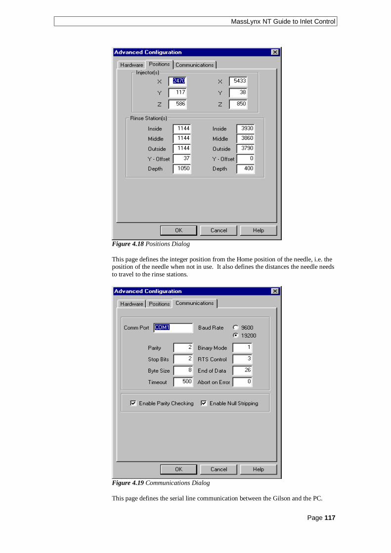
MassLynx NT Guide to Inlet Control
Page 117
Figure 4.18 Positions Dialog
This page defines the integer position from the Home position of the needle, i.e. theposition of the needle when not in use. It also defines the distances the needle needsto travel to the rinse stations.
Figure 4.19 Communications Dialog
This page defines the serial line communication between the Gilson and the PC.

MassLynx NT Guide to Inlet Control
Page 118
Gilson Pump
The Gilson Pump pages can be accessed by selecting Gilson Pump from the View
menu on the Inlet Editor or by pressing the toolbar button.
n Gilson Solvents and Flows Page
Figure 4.20 Solvents and Flows page
Solvents Up to four solvents will be displayed depending upon the systemconfiguration. The total value of all the solvent percentages added together must notexceed 100%.
Pump A This is the remainder percentage after the solvent percentages have beenset for the other pumps.
Pump B, C, D These can either be enabled or disabled by checking the box nextto the individual pumps. The values can be set to the required percentage of flowdelivery.
Solvent Name Type in the solvent name.
Refill Time This is the time required for the piston return stroke. Normally it is setto the lowest value (125ms). If cavitation or degassing occurs, then a higher valuemust be used. The minimum value is 125ms and the maximum 1000ms.
Compressibility This is used to calculate a flow rate compensation for thecompressibility of the solvent. See the Gilson User Guide for suitable values.
Run Time This is the length of time, in minutes, the pump should run for.
Flow Rate This is the total flow rate of the solvent channels according to how youhave configured the instrument.

MassLynx NT Guide to Inlet Control
Page 119
n Gilson Gradient Timetable Page
Figure 4.21 Gradient Timetable page
This page allows a gradient to be entered and edited. To operate in isocratic modeensure that the timetable is empty.
To add a gradient, type in a time, the required percentages and the flow rate, in the
relevant boxes and press the toolbar button. Note: The first entry must have atime of 0.
To delete a single gradient click with left mouse button on a time in the list and
press the toolbar button.
To delete all entries press the toolbar button. This button is only availablewhen there are entries in the timetable.
To modify a gradient, select the required entry in the timetable. The values will thenbe displayed in the edit boxes above the timetable, and can be altered as appropriate.
Once changed press to re-enter the values into the timetable. If, however, youmodify the time value such that it does not correspond to any existing entry in the
timetable pressing will result in a new entry being created in the timetable.

MassLynx NT Guide to Inlet Control
Page 120
n Gilson Events Timetable Page
Figure 4.22 Events Timetable page
To add an event, enter a time, select an event from drop down box and press the
toolbar button.
To delete a single event, click with left mouse button on a time in the list and press
the toolbar button.
To delete all entries press the toolbar button.
To modify an event, select the required entry in the timetable. The values will thenbe displayed in the edit boxes above the timetable, and can be altered as appropriate.
Once changed press to re-enter the values into the timetable. If, however, youmodify the time value such that it does not correspond to any existing entry in the
timetable pressing will result in a new entry being created in the timetable.
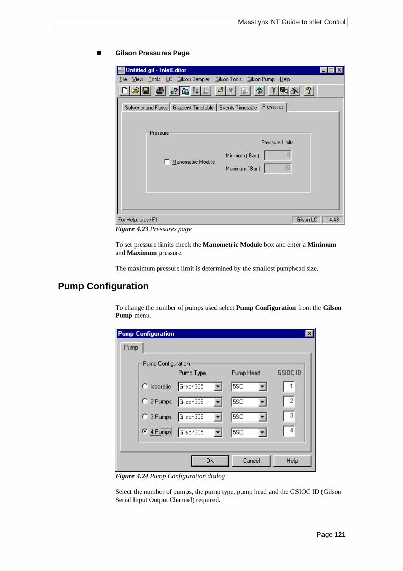
MassLynx NT Guide to Inlet Control
Page 121
n Gilson Pressures Page
Figure 4.23 Pressures page
To set pressure limits check the Manometric Module box and enter a Minimumand Maximum pressure.
The maximum pressure limit is determined by the smallest pumphead size.
Pump Configuration
To change the number of pumps used select Pump Configuration from the GilsonPump menu.
Figure 4.24 Pump Configuration dialog
Select the number of pumps, the pump type, pump head and the GSIOC ID (GilsonSerial Input Output Channel) required.

MassLynx NT Guide to Inlet Control
Page 122

MassLynx NT Guide to Inlet Control
Page 123
Notes................................................................................................................................................................
................................................................................................................................................................
................................................................................................................................................................
................................................................................................................................................................
................................................................................................................................................................
................................................................................................................................................................
................................................................................................................................................................
................................................................................................................................................................
................................................................................................................................................................
................................................................................................................................................................
................................................................................................................................................................
................................................................................................................................................................
................................................................................................................................................................
................................................................................................................................................................
................................................................................................................................................................
................................................................................................................................................................
................................................................................................................................................................
................................................................................................................................................................
................................................................................................................................................................
................................................................................................................................................................
................................................................................................................................................................
................................................................................................................................................................
................................................................................................................................................................
................................................................................................................................................................
................................................................................................................................................................
................................................................................................................................................................
................................................................................................................................................................

MassLynx NT Guide to Inlet Control
Page 124
Notes................................................................................................................................................................
................................................................................................................................................................
................................................................................................................................................................
................................................................................................................................................................
................................................................................................................................................................
................................................................................................................................................................
................................................................................................................................................................
................................................................................................................................................................
................................................................................................................................................................
................................................................................................................................................................
................................................................................................................................................................
................................................................................................................................................................
................................................................................................................................................................
................................................................................................................................................................
................................................................................................................................................................
................................................................................................................................................................
................................................................................................................................................................
................................................................................................................................................................
................................................................................................................................................................
................................................................................................................................................................
................................................................................................................................................................
................................................................................................................................................................
................................................................................................................................................................
................................................................................................................................................................
................................................................................................................................................................
................................................................................................................................................................
................................................................................................................................................................

MassLynx NT Guide to Inlet Control
Page 125
Hewlett Packard SystemsChapter 5
Hewlett Packard 5890 Gas Chromatograph
Both the HP5890 Series I and Series II can be controlled by MassLynx. For theSeries II instrument it is necessary to configure the GC to respond to Series Icommands by setting a jumper in the GC. Your installation engineer will have donethis. Before starting to use the GC the software must be configured to reflect the GCequipment in use e.g. the number of injectors and detectors etc.
n To change GC Parameters (Hewlett Packard 5890 Gas Chromatograph)
1. Choose Set up Inlet from the Acquisition Control Panel Instrument menu
or
Double click on the picture of the GC on the Acquisition Control Panel tobring up the HP5890 inlet editor shown below.
2. Make any changes to the parameters. Note: The oven temperature ramp canbe modified either by using the keyboard to type in times, temperatures andrates, or by dragging the small red handles on the graph itself using themouse.
3. Save the method using either Save or Save As from the File menu.
Figure 5.1 HP5890 Editor
The time and temperature range of the oven temperature ramp can be controlled
using the buttons that appear to the right of the ramp. Clicking on will increase
the range shown on the time axis, clicking on will increase the range shown on
the temperature axis. Clicking on alters the display ranges so that the oventemperature display fills the graph.
A full description of all the parameters in this editor is given in the HP5890 GasChromatograph Reference Manual.

MassLynx NT Guide to Inlet Control
Page 126
n To Change GC Configuration (Hewlett Packard 5890 GasChromatograph)
1. Choose Configuration from the HP5890 Edit menu to display theconfiguration editor shown below.
2. Make any changes to the parameters.
3. Press OK. The parameters will be saved with the GC method when eitherSave or Save As is selected from the HP5890 File menu. Buttons in theHP5890 Edit menu that are not appropriate for the selected configuration willbe grayed out.
Figure 5.2 HP5890 Configuration Editor
The main HP5890 editor is used to set up the GC oven temperature program and tocontrol the dump valve and cryogenic cooling options if fitted.
n To change Purge Valve Times (Hewlett Packard 5890 GasChromatograph)
Figure 5.3 HP5890 Purge Valve Editor

MassLynx NT Guide to Inlet Control
Page 127
Hewlett Packard 7673A Auto Injector
The HP 7673A auto injector can only be used with the HP 5890 gas chromatograph.
Figure 5.4 HP7673A Auto Injector Editor
Note: This dialog only applies if the Dice option is selected at setup, if the Diceoption is not selected a “No parameters to set” message is displayed.
n To Change Autosampler parameters (Hewlett Packard 7673A AutoInjector)
1. Choose Set up Auto Injector from the Acquisition Control Panel Instrumentmenu
or
Double click on the picture of the auto injector on the Acquisition ControlPanel to display the HP7673A editor shown above.
2. Make any changes to the parameters.
3. Save the method using either Save or Save As from the File menu.
A full description of all the parameters in this editor is given in the HP7673AAutomatic Sampler Operating Manual.
An autosampler will usually be used with the multiple sample acquisition pagewhere further information such as bottle number will be entered. Starting anacquisition with an autosampler will be covered in the next section

MassLynx NT Guide to Inlet Control
Page 128
Hewlett Packard HPLC Systems
The HP1050, HP1090 and HP1100 HPLC systems can be controlled fromMassLynx. All three photo diode array (PDA) and UV detectors are supported.
The software can be used to control the pump during instrument tuning oracquisition and can be used to provide multi-sample acquisitions. Both isocratic andgradient modes of operation are supported.
The HP1050 is described in the examples below. Differences for the HP1090 andHP1100 are also described.
n Hewlett Packard Sampler Configuration Page
Select the HP1050 AutoSampler, HP1090 AutoSampler or HP1100
AutoSampler from the View menu or press the toolbar button.
Figure 5.5 HP1050 Sampler Initial Conditions Window
Injection Volume This is the volume in microlitres to inject.
Note: If you are running from the Sample List the injection volume in the samplelist entry overrides the setting defined here.
Draw Speed This determines the rate in microlitres per minute at which sample isextracted into the autosampler needle. This should be set according to the viscosityof your sample.
Eject Speed This is the speed in microlitres per minute at which sample is ejectedfrom the needle on injection. Again set this according to the viscosity of the sample.Consult your HP documentation for further information. Note: This facility is onlyavailable with the HP1050 and HP1100 and will not be visible on an HP1090system.

MassLynx NT Guide to Inlet Control
Page 129
Draw Position This is an offset value in mm from position 0 and determines howfar the needle is inserted into your sample. Consult your HP documentation forfurther information. Again this facility is only available with the HP1050 andHP1100 and will not be visible on an HP1090 system.
Stop Time This value is set in minutes to be the time that the autosampler methodwill run after injection. This does not apply to the HP1090 since this has an in-builtautosampler.
External Vial Tray If an external vial tray is used check this box.
Vial number The vial to inject from.
Note: If a multisample acquisition is being run from the MassLynx Sample List, theBottle # entry in the sample list overrides the value defined in the Vial Number box.
Syringe Size Set this to the size of syringe fitted on the HP1090 LC System. Thisparameter applies to the HP1090 only and will not be visible in a HP1050 orHP1100 system.
Thermostat On If the autosampler is fitted with a sample heater then this box willbe enabled. Check it to use the sample heater. This parameter applies to theHP1100 only and will not be visible in a HP1050 or HP1090 system.
Sample Temperature Enter the temperature to heat the sample to. Thisparameter applies to the HP1100 only and will not be visible in a HP1050 orHP1090 system.
n Hewlett Packard Sampler External Events Page
External events allow control of the external contacts found on the HP1050 andHP1090 LC systems. In addition HP1090 column switching can also be controlled.For the HP1100 a separate contact board must be installed in the pump in order touse this functionality.
Figure 5.6 HP1050 AutoSampler External Events page

MassLynx NT Guide to Inlet Control
Page 130
The contacts can be set to operate under timed control during a method run, as wellas having their initial states set. The contacts will be in the initial state before amethod run and will return to this state after a method has completed.
To add an event, enter a Time, select an Event Type from the drop down list box
and press the toolbar button.
To delete a single event click with left mouse button on a time in the list and press
the toolbar button.
To delete all entries press the toolbar button. This button is only availablewhen there are entries in the timetable.
To change the State of a contact, double click on the time entry in the list to togglebetween states.
Time The time in minutes at which the contact event should occur.
Event The contact event to be performed.
State The state determines whether the contact is to be opened or closed.
n Hewlett Packard Pump Initial Conditions Page
Select the HP1050 Pump, HP1090 Pump or HP1100 Pump from the View menu
or press the toolbar button.
Figure 5.7 HP1050 Pump Initial Conditions page
Solvents Up to four solvents will be displayed depending upon the systemconfiguration. The total value of all the solvent percentages added together must notexceed 100%.
Pump A This is the remainder percentage after the solvent percentages have beenset for the other pumps.

MassLynx NT Guide to Inlet Control
Page 131
Pump B, C, D These can either be enabled or disabled by checking the box nextto the individual pumps. The values can be set to the required percentage of flowdelivery.
Flow This is the total flow rate of the solvent channels according to how you haveconfigured the instrument.
Pressures These set the upper and lower limits of the pressure within the solventdelivery system (SDS) if the pressure falls outside of this range the SDS switchesoff.
Column Heater If the instrument has an oven present then the columntemperature can be set to a specified temperature in degrees centigrade. Check theColumn Temperature box and enter a temperature. If the software has beenconfigured to operate without a column oven then these boxes will be grayed out.Note: For the HP1100 a temperature should be entered in both the Left and Rightboxes.
Stop Time This value is set to the time in minutes that the method will run fromthe point of injection.
n Hewlett Packard Pump Gradient Timetable Page
Figure 5.8 HP1050 Pump Gradient page
This page allows a gradient to be entered and edited. To operate in isocratic modeensure the timetable is empty.
To add a gradient, type in a time and percentage in the relevant boxes and press the
toolbar button. Note: The first entry must have a time of 0.
To delete a single gradient, click with left mouse button on a time in the list and
press the toolbar button.
To delete all entries press the toolbar button. This button is only availablewhen there are entries in the timetable.
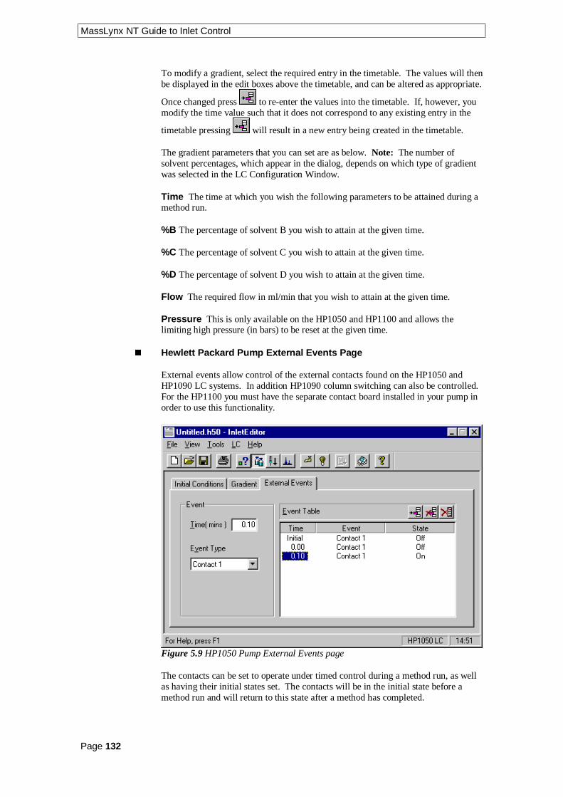
MassLynx NT Guide to Inlet Control
Page 132
To modify a gradient, select the required entry in the timetable. The values will thenbe displayed in the edit boxes above the timetable, and can be altered as appropriate.
Once changed press to re-enter the values into the timetable. If, however, youmodify the time value such that it does not correspond to any existing entry in the
timetable pressing will result in a new entry being created in the timetable.
The gradient parameters that you can set are as below. Note: The number ofsolvent percentages, which appear in the dialog, depends on which type of gradientwas selected in the LC Configuration Window.
Time The time at which you wish the following parameters to be attained during amethod run.
%B The percentage of solvent B you wish to attain at the given time.
%C The percentage of solvent C you wish to attain at the given time.
%D The percentage of solvent D you wish to attain at the given time.
Flow The required flow in ml/min that you wish to attain at the given time.
Pressure This is only available on the HP1050 and HP1100 and allows thelimiting high pressure (in bars) to be reset at the given time.
n Hewlett Packard Pump External Events Page
External events allow control of the external contacts found on the HP1050 andHP1090 LC systems. In addition HP1090 column switching can also be controlled.For the HP1100 you must have the separate contact board installed in your pump inorder to use this functionality.
Figure 5.9 HP1050 Pump External Events page
The contacts can be set to operate under timed control during a method run, as wellas having their initial states set. The contacts will be in the initial state before amethod run and will return to this state after a method has completed.

MassLynx NT Guide to Inlet Control
Page 133
To add an event, type in a Time and select an Event Type from the drop down list
box and press the toolbar button.
To delete a single event, click with left mouse button on a time in the list and press
the toolbar button.
To delete all entries press the toolbar button. This button is only availablewhen there are entries in the timetable.
To change the State of a contact, double click on the time entry in the list to togglebetween states.
Time The time in minutes at which you would like the contact event to occur.
Event Type This determines the contact event to be displayed in the list of events.Once displayed, the events can be added, deleted or changed as described above.
State The state determines whether the contact is to be opened or closed.
n To Set-up the Diode Array Detector (Hewlett Packard)
Select the HP1050 PDA Detector from the View menu or press the toolbarbutton.
Figure 5.10 HP1050 DAD Spectrum Window
Range Enter the minimum (Range) and maximum (To) wavelengths innanometers over which diode array spectral data will be acquired.
Peak Width Determines the rate at which the data is acquired. There areapproximately eight spectra per peak so a peak width of 0.1 minutes means eightspectra will be acquired every 6 seconds.
Interval This determines the number of spectral data points acquired. For examplean interval of 4 nanometers means data points will be acquired at the lowerwavelength, the lower wavelength plus 4nm and so on.

MassLynx NT Guide to Inlet Control
Page 134
Autobalance Check this box to zero the base line of the diode array detectorbefore each analysis.
Use Pump Stop Time Check this box use the Stop Time defined on the PumpInitial Conditions page (see page 130).
Stop Time This option is not enabled if the Use Pump Stop Time box is checked.It determines the time in minutes the diode array method will run. Data will beacquired for this amount of time.
Save Data to Disk Check this box to store the diode array data to disk. If you donot wish to save the diode array data to disk you should uncheck this box.
n HP1100 DAD
The HP1100 DAD dialog has Pre Autobalance and Post Autobalance in place ofAutobalance. Check the relevant box to zero the baseline of the diode arraydetector before or after each analysis.
n Hewlett Packard 1050 UV Detector
Select HP1050 UV Detector from the View menu or press the toolbar button.
Figure 5.11 HP1050 UV Detector Window
Response Select 250, 1000 or 4000 msec from the drop down list box.
Wavelength Enter the wavelength in nanometers to be monitored.

MassLynx NT Guide to Inlet Control
Page 135
n Hewlett Packard 1090 UV Detector
Select HP1090 UV Detector from the View menu or press the toolbar button.
Figure 5.12 HP1090 UV Detector Window
Response Select one of the values from the drop down list.
Attenuation Select one of the values from the drop down list.
Zero Percent Increase the value to increase the baseline.
Filter Position Set this to the number of the filter required.
Lamp Current Set to Normal or High.

MassLynx NT Guide to Inlet Control
Page 136
n Hewlett Packard 1100 UV Detector
Select HP1100 UV Detector from the View menu or press the toolbar button.
Figure 5.13 HP1100 UV Detector Window
Wavelength Set to the wavelength in nanometers to be monitored.
Response Select one of the values from the drop down list.
Zero Offset Increase the value to increase the baseline.
Attenuation Select one of the values from the drop down list.

MassLynx NT Guide to Inlet Control
Page 137
The HP6890 System Status Page
The System Status page displays information about the state of the machine beingcontrolled. This page can be accessed from the Inlet Editor by selecting Status from
the View menu or by pressing the toolbar button.
Figure 5.14 System Status page
Indicators The Running and Injector Cycle indicators at the left of the screen giveinformation on the current status of the GC system. The OK and Ready Indicatorsbecome illuminated in red if the GC System has an error. Click on the red indicatorsto display more information on the cause of the error.
Run Time This displays how long the method has been running.
Flow Rate This is the current flow rate as returned by the instrument. The currentvalue will be the setpoint when using a flow based mode or the actual flow if in apressure based mode.
Pressure This displays the current pressure in the instrument. The current valuewill be the setpoint when using a pressure based mode or the actual pressure if in aflow based mode.
Temperature This displays the current oven temperature of the GC.

MassLynx NT Guide to Inlet Control
Page 138
n HP6890 Sampler Configuration Page
Select the HP6890 AutoSampler from the View menu or press the toolbarbutton.
Figure 5.15 HP6890 Status and Connectivity page
Fault A red light indicates that the Autosampler has developed a fault.
Running A green light indicates that the Autosampler is active. The Autosampleris active if it is moving a vial, rinsing or injecting.
Ready A green light indicates that the Autosampler is ready to start processinganother vial.
Autosampler Has Tray Check this box if the Autosampler has a tray.
Autosampler Has Barcode Reader Check this box if the Autosampler has abarcode reader.
Sample Number Enter the vial number that the injection will be taken from,when the start button is pressed.
Start Press this button to start an autosampler (and hence GC) run with thecurrently stored method.
Stop Press this button to stop the Autosampler. It will not stop a GC run.
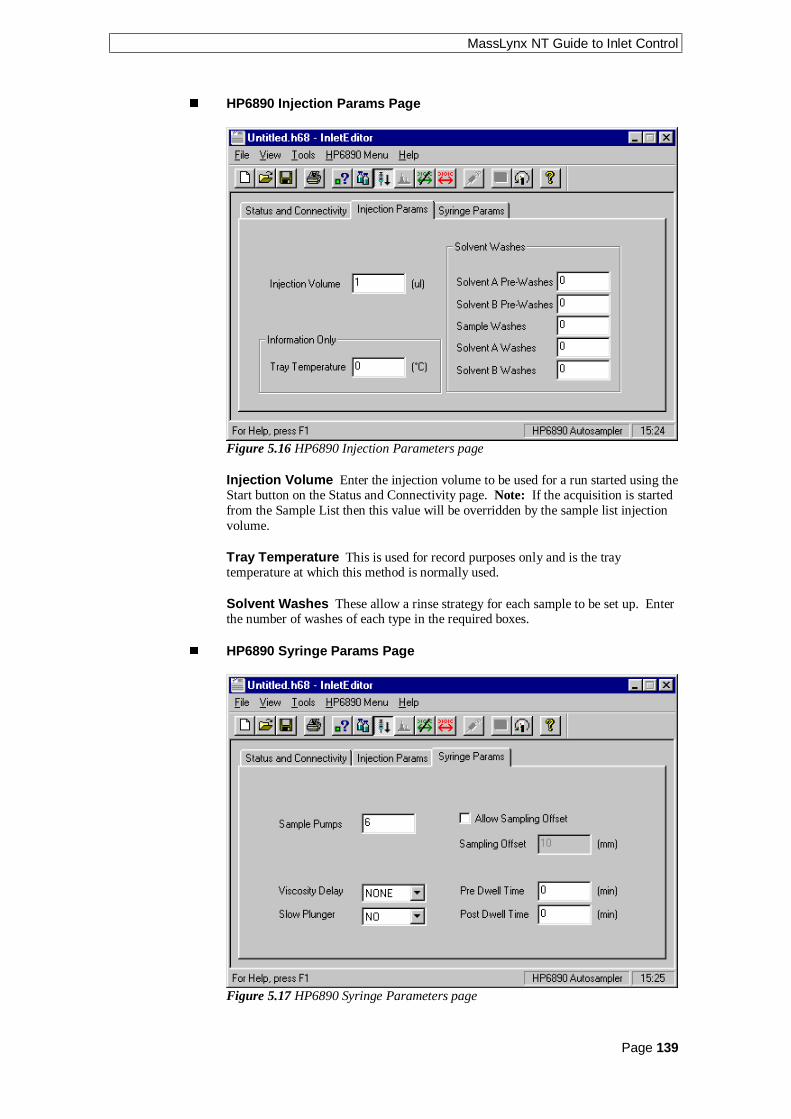
MassLynx NT Guide to Inlet Control
Page 139
n HP6890 Injection Params Page
Figure 5.16 HP6890 Injection Parameters page
Injection Volume Enter the injection volume to be used for a run started using theStart button on the Status and Connectivity page. Note: If the acquisition is startedfrom the Sample List then this value will be overridden by the sample list injectionvolume.
Tray Temperature This is used for record purposes only and is the traytemperature at which this method is normally used.
Solvent Washes These allow a rinse strategy for each sample to be set up. Enterthe number of washes of each type in the required boxes.
n HP6890 Syringe Params Page
Figure 5.17 HP6890 Syringe Parameters page

MassLynx NT Guide to Inlet Control
Page 140
Sample Pumps Enter the number of times the syringe will draw in liquid in orderto fill it.
Viscosity Delay Select the length of time that the needle will stay in the vial toensure that all the sample has been drawn into the syringe, from the drop down listbox.
Slow Plunger For viscous liquids select YES from the drop down list boxotherwise select NO.
Allow Sampling Offset Check this box to enable the Sampling Offset.
Sampling Offset Enter the distance from the bottom of the vial (in millimeters)that the injection will be taken from. This is to allow samples to be taken fromdifferent parts of a multi-phased sample. Note: This box will bot be enabled unlessthe Allow Sampling Offset box is checked.
Pre Dwell Time and Post Dwell Time If, for example the sample needs heatingbefore injection, the syringe needle can be held in the GC inlet for Pre Dwell Timeand/or Post Dwell Time. Enter the length of time in the relevant box.
n To Set-up the Pump (HP6890)
Select the HP6890 Pump from the View menu or press the toolbar button.
n HP6890 Status Page
Figure 5.18 HP6890 GC Status page
Prep Run This will be yellow when the GC is in the Prep Run state. This occurswhen the GC is trying to equilibrate before an automatic injection start.
Running This will be yellow when the GC is in the Running state. This occurswhen the GC has started its temperature and/or pressure profiles for a run.
Post Run This will be yellow when the GC is in the Post Run state.
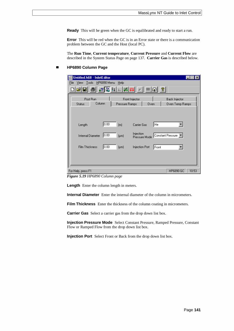
MassLynx NT Guide to Inlet Control
Page 141
Ready This will be green when the GC is equilibrated and ready to start a run.
Error This will be red when the GC is in an Error state or there is a communicationproblem between the GC and the Host (local PC).
The Run Time, Current temperature, Current Pressure and Current Flow aredescribed in the System Status Page on page 137. Carrier Gas is described below.
n HP6890 Column Page
Figure 5.19 HP6890 Column page
Length Enter the column length in meters.
Internal Diameter Enter the internal diameter of the column in micrometers.
Film Thickness Enter the thickness of the column coating in micrometers.
Carrier Gas Select a carrier gas from the drop down list box.
Injection Pressure Mode Select Constant Pressure, Ramped Pressure, ConstantFlow or Ramped Flow from the drop down list box.
Injection Port Select Front or Back from the drop down list box.

MassLynx NT Guide to Inlet Control
Page 142
n HP6890 Pressure Ramps Page
Figure 5.20 HP6890 Pressure Ramps page
This appearance of this page will vary depending on the Injection Pressure Modeselected on the Column page. If Constant Pressure was selected only InitialPressure and Initial Time are enabled. If Ramped Pressure was selected then theRamps are enabled as well. If Constant Flow or Ramped Flow was selected, theparameters will be as for the corresponding Pressure page but Pressure will bereplaced by Flow.
Initial Pressure/Flow Enter the pressure/flow required for the Initial state.
Initial Time Enter the length of time to remain at the initial pressure/flow
Ramps To enable a Ramp check the relevant Ramp box or enter a non-zero valuein the Rate box.
Rate Enter rate of pressure/flow change for current ramp.
Temp Enter final pressure/flow for current ramp.
Time Enter the length of time to remain at the final pressure/flow of current ramp,before proceeding to the next ramp.
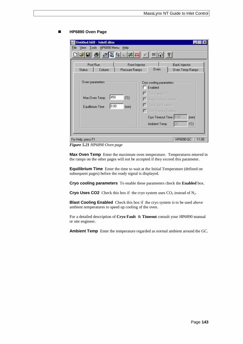
MassLynx NT Guide to Inlet Control
Page 143
n HP6890 Oven Page
Figure 5.21 HP6890 Oven page
Max Oven Temp Enter the maximum oven temperature. Temperatures entered inthe ramps on the other pages will not be accepted if they exceed this parameter.
Equilibrium Time Enter the time to wait at the Initial Temperature (defined onsubsequent pages) before the ready signal is displayed.
Cryo cooling parameters To enable these parameters check the Enabled box.
Cryo Uses CO2 Check this box if the cryo system uses CO2 instead of N2.
Blast Cooling Enabled Check this box if the cryo system is to be used aboveambient temperatures to speed up cooling of the oven.
For a detailed description of Cryo Fault & Timeout consult your HP6890 manualor site engineer.
Ambient Temp Enter the temperature regarded as normal ambient around the GC.
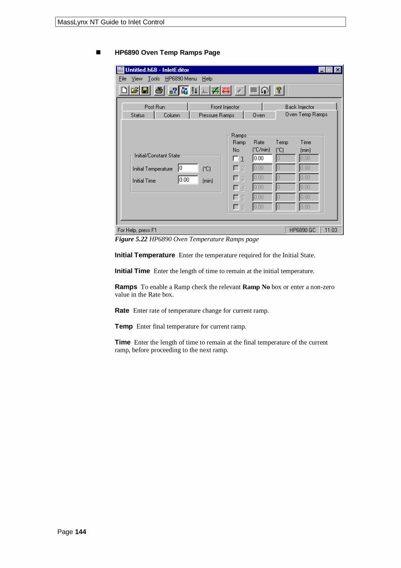
MassLynx NT Guide to Inlet Control
Page 144
n HP6890 Oven Temp Ramps Page
Figure 5.22 HP6890 Oven Temperature Ramps page
Initial Temperature Enter the temperature required for the Initial State.
Initial Time Enter the length of time to remain at the initial temperature.
Ramps To enable a Ramp check the relevant Ramp No box or enter a non-zerovalue in the Rate box.
Rate Enter rate of temperature change for current ramp.
Temp Enter final temperature for current ramp.
Time Enter the length of time to remain at the final temperature of the currentramp, before proceeding to the next ramp.

MassLynx NT Guide to Inlet Control
Page 145
n HP6890 Post Run Page
Figure 5.23 HP6890 Post Run page
This appearance of this page will vary depending on the Injection Pressure Modeselected on the Column page. If Constant Pressure or Ramped Pressure wasselected then a Post Run Pressure is required. If Constant Flow or Ramped Flowwas selected then a Post Run Flow is required.
Post Run Enabled Check this box if a Post Run is required.
Time Enter the length of time for the post run phase.
Temp Enter the temperature for the post run phase.
Pressure/Flow Enter the head pressure/flow for the post run phase.

MassLynx NT Guide to Inlet Control
Page 146
n HP6890 Front and Back Injector Pages
Figure 5.24 HP6890 Front Injector page
Injection Port Type If None is selected there are no parameters to enter.
Cool on Column
If Track Oven is selected there are no parameters to enter.
If Ramped Temperature is selected Figure 5.24 is displayed.
Thermal Zone On Check this box to enable the Temperature, Time and Rampsfields.
The Initial/Static conditions and Ramps details are used to provide a temperatureprofile for the inlet independent to the temperature profile of the oven, but themethod of use is the same.
Initial Temperature Enter the temperature required for the Initial State.
Initial Time Enter the length of time to remain at the initial temperature.
Ramps To enable a Ramp check the relevant Ramp box or enter a non-zero valuein the Rate box.
Rate Enter rate of temperature change for current ramp.
Final Temp Enter final temperature for current ramp.
Time Enter the length of time to remain at the final temperature of the currentramp, before proceeding to the next ramp.

MassLynx NT Guide to Inlet Control
Page 147
Split/Splitless
If None is selected there are no parameters to enter.
If Split is selected Figure 5.25 is displayed.
Figure 5.25 HP6890 Front Injector page - Split
Gas Saver Enabled Check this box to save gas after an injection.
Note: Auto prep run must be manually set to ON if this box is checked. See theHP6890 manual for details.
Flow Enter the reduced flow rate.
Time Enter the length of time to deliver the reduced flow rate for.
Thermal Zone On Check this box to enable the Temperature and Split Ratiofields.
Temperature Enter the temperature at which to hold the inlet during the run.
Split Ratio Enter the split ratio for the inlet flow.

MassLynx NT Guide to Inlet Control
Page 148
If Splitless is selected Figure 5.26 is displayed.
Figure 5.26 HP6890 Front Injector page - Splitless
Gas Saver Enabled Check this box to save gas after an injection.
Note: Auto prep run must be manually set to ON if this box is checked. See theHP6890 manual for details.
Flow Enter the reduced flow rate.
Time Enter the length of time to deliver the reduced flow rate for.
Thermal Zone On Check this box to enable the Temperature, Purge Time andPurge Flow fields.
Temperature Enter the temperature at which to hold the inlet during the run.
Purge Time Enter the time at which to open the purge valve.
Purge Flow Enter the flow rate to use at the Purge Time.

MassLynx NT Guide to Inlet Control
Page 149
PTV
If None is selected there are no parameters to enter.
If any other option is selected Figure 5.27 is displayed.
Figure 5.27 HP6890 Front Injector page
PTV Cryo Parameters Enabled Check this box enable the other options on thisdialog.
Quick Cool Check this box to Enter the reduced flow rate.
Time Enter the length of time to deliver the reduced flow rate for.
Thermal Zone On Check this box to enable the Temperature and Split Ratiofields.
Temperature Enter the temperature at which to hold the inlet during the run.
Split Ratio Enter the split ratio for the inlet flow.
Max Oven Temp Enter the maximum oven temperature.
Equilibrium Time Enter the time required to reach equilibrium at the newtemperature.
Cryo cooling parameters To enable these parameters check the Enabled box.
Cryo Uses CO2 Check this box if the cryo system uses CO2 instead of N2.
Blast Cooling Enabled Check this box if the cryo system is to be used aboveambient temperatures to speed up cooling of the oven.
For a detailed description of Cryo Fault & Timeout consult your HP6890 manualor site engineer.

MassLynx NT Guide to Inlet Control
Page 150
Ambient Temp Enter the temperature regarded as normal ambient around the GC.
Flow Enter the reduced flow rate.
Time Enter the length of time to deliver the reduced flow rate for.
Thermal Zone On Check this box to enable the Temperature, Purge Time andPurge Flow fields.
Temperature Enter the temperature at which to hold the inlet during the run.
Purge Time Enter the time at which to open the purge valve.
Purge Flow Enter the flow rate to use at the Purge Time.
The Back Injector parameters are edited in the same way as those for the Frontinjector.
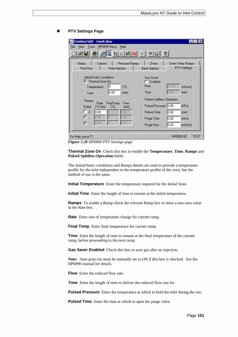
MassLynx NT Guide to Inlet Control
Page 151
n PTV Settings Page
Figure 5.28 HP6890 PTV Settings page
Thermal Zone On Check this box to enable the Temperature, Time, Ramps andPulsed Splitless Operation fields.
The Initial/Static conditions and Ramps details are used to provide a temperatureprofile for the inlet independent to the temperature profile of the oven, but themethod of use is the same.
Initial Temperature Enter the temperature required for the Initial State.
Initial Time Enter the length of time to remain at the initial temperature.
Ramps To enable a Ramp check the relevant Ramp box or enter a non-zero valuein the Rate box.
Rate Enter rate of temperature change for current ramp.
Final Temp Enter final temperature for current ramp.
Time Enter the length of time to remain at the final temperature of the currentramp, before proceeding to the next ramp.
Gas Saver Enabled Check this box to save gas after an injection.
Note: Auto prep run must be manually set to ON if this box is checked. See theHP6890 manual for details.
Flow Enter the reduced flow rate.
Time Enter the length of time to deliver the reduced flow rate for.
Pulsed Pressure Enter the temperature at which to hold the inlet during the run.
Pulsed Time Enter the time at which to open the purge valve.

MassLynx NT Guide to Inlet Control
Page 152
Purge Time Enter the time at which to open the purge valve.
Purge Flow Enter the flow rate to use at the Purge Time.
n HP6890 Communication Parameters
Select View Comms Settings from the HP6890 Menu or press the toolbarbutton to view the current communications settings.
Communication settings should only be changed by an engineer, the Edit Comms
Settings and the toolbar button allow this to be done.
Figure 5.29 HP6890 Communications Parameters dialog

MassLynx NT Guide to Inlet Control
Page 153
The HP6890 Toolbar
The HP6890 toolbar has five extra buttons on it, which are:
Click To
View current communications settings.
Edit current communications settings.
Start and stop method.
Turn GC on and off.
Reset Autosampler

MassLynx NT Guide to Inlet Control
Page 154

MassLynx NT Guide to Inlet Control
Page 155
Notes................................................................................................................................................................
................................................................................................................................................................
................................................................................................................................................................
................................................................................................................................................................
................................................................................................................................................................
................................................................................................................................................................
................................................................................................................................................................
................................................................................................................................................................
................................................................................................................................................................
................................................................................................................................................................
................................................................................................................................................................
................................................................................................................................................................
................................................................................................................................................................
................................................................................................................................................................
................................................................................................................................................................
................................................................................................................................................................
................................................................................................................................................................
................................................................................................................................................................
................................................................................................................................................................
................................................................................................................................................................
................................................................................................................................................................
................................................................................................................................................................
................................................................................................................................................................
................................................................................................................................................................
................................................................................................................................................................
................................................................................................................................................................
................................................................................................................................................................

MassLynx NT Guide to Inlet Control
Page 156
Notes................................................................................................................................................................
................................................................................................................................................................
................................................................................................................................................................
................................................................................................................................................................
................................................................................................................................................................
................................................................................................................................................................
................................................................................................................................................................
................................................................................................................................................................
................................................................................................................................................................
................................................................................................................................................................
................................................................................................................................................................
................................................................................................................................................................
................................................................................................................................................................
................................................................................................................................................................
................................................................................................................................................................
................................................................................................................................................................
................................................................................................................................................................
................................................................................................................................................................
................................................................................................................................................................
................................................................................................................................................................
................................................................................................................................................................
................................................................................................................................................................
................................................................................................................................................................
................................................................................................................................................................
................................................................................................................................................................
................................................................................................................................................................
................................................................................................................................................................
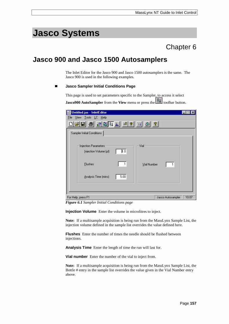
MassLynx NT Guide to Inlet Control
Page 157
Jasco SystemsChapter 6
Jasco 900 and Jasco 1500 Autosamplers
The Inlet Editor for the Jasco 900 and Jasco 1500 autosamplers is the same. TheJasco 900 is used in the following examples.
n Jasco Sampler Initial Conditions Page
This page is used to set parameters specific to the Sampler, to access it select
Jasco900 AutoSampler from the View menu or press the toolbar button.
Figure 6.1 Sampler Initial Conditions page
Injection Volume Enter the volume in microlitres to inject.
Note: If a multisample acquisition is being run from the MassLynx Sample List, theinjection volume defined in the sample list overrides the value defined here.
Flushes Enter the number of times the needle should be flushed betweeninjections.
Analysis Time Enter the length of time the run will last for.
Vial number Enter the number of the vial to inject from.
Note: If a multisample acquisition is being run from the MassLynx Sample List, theBottle # entry in the sample list overrides the value given in the Vial Number entryabove.

MassLynx NT Guide to Inlet Control
Page 158
Jasco 900 and Jasco 1500 Pumps
The Inlet Editor for the Jasco 900 and Jasco 1500 pumps is the same. The Jasco 900is used in the following examples.
The Jasco Pump pages can be accessed by selecting Jasco900 Pump from the View
menu on the Inlet Editor or by pressing the toolbar button.
n Jasco Initial Conditions Page
Figure 6.2 Initial Conditions page
Solvents Up to three solvents will be displayed depending upon the systemconfiguration. The total value of all the solvent percentages added together must notexceed 100%.
Pump A This is the remainder percentage after the solvent percentages have beenset for the other pumps.
Pump B and C Check the box for the pump required and enter the percentage offlow to deliver from this pump. To disable the pump, uncheck the box.
Flow This is the total flow rate of the solvent channels.
Mode Select Isocratic (One pump), Binary (Two pumps), HPG (High PressureGradient) or LPG (Low Pressure Gradient).
Pressures Enter the upper and lower limits of the pressure within the solventdelivery system (SDS), if the pressure falls outside of this range the SDS switchesoff.
Column Heater If the instrument has an oven present then the columntemperature can be set to a specified temperature in degrees centigrade. Check theColumn Temperature box and enter a temperature. If the software has beenconfigured to operate without a column oven then these boxes will be greyed out.

MassLynx NT Guide to Inlet Control
Page 159
Stop Time Enter the time in minutes that the method will run from the point ofinjection. If a Jasco Autosampler has also been selected, Analysis Time on theautosampler page overrides this value.
Post Time Enter the time in minutes that the instrument will run in its initialconditions after a method has completed. No further injections can be carried outwhilst the system is in postrun thus allowing re-equilibration of the column.
n Jasco Gradient Page
Figure 6.3 Gradient Timetable page
This page allows a gradient to be entered and edited. If isocratic mode was selectedon the Initial Conditions page then all fields will be greyed out and
is displayed.
To add a gradient, enter a time and percentage in the relevant boxes and press the
toolbar button. Note: The first entry must have a time of 0.
To delete a single gradient, click with left mouse button on a time in the list and
press the toolbar button.
To delete all entries press the toolbar button. This button is only availablewhen there are entries in the timetable.
To modify a gradient select the required entry in the timetable. The values will thenbe displayed in the edit boxes to the right of the timetable and can be altered as
appropriate. Once changed press to re-enter the values into the timetable.Note: If the time is changed and the new time does not correspond with an existingentry in the table, then a new entry will be added. If the new time correspond to anexisting entry then the entry at that time will be overwritten.

MassLynx NT Guide to Inlet Control
Page 160
Jasco 900 and Jasco 1500 UV Detectors
The Inlet Editor for the Jasco 900 and Jasco 1500 UV detectors is the same. TheJasco 900 is used in the following examples.
This page is used to set parameters specific to the UV detector, to access it select
Jasco900 UV Detector from the View menu or press the toolbar button.
Figure 6.4 UV Detector Configuration page
Response This can be set to Fast, Standard or Slow depending on the length oftime you expect the peak to appear.
Wavelength Set to the wavelength you want to monitor.

MassLynx NT Guide to Inlet Control
Page 161
Notes................................................................................................................................................................
................................................................................................................................................................
................................................................................................................................................................
................................................................................................................................................................
................................................................................................................................................................
................................................................................................................................................................
................................................................................................................................................................
................................................................................................................................................................
................................................................................................................................................................
................................................................................................................................................................
................................................................................................................................................................
................................................................................................................................................................
................................................................................................................................................................
................................................................................................................................................................
................................................................................................................................................................
................................................................................................................................................................
................................................................................................................................................................
................................................................................................................................................................
................................................................................................................................................................
................................................................................................................................................................
................................................................................................................................................................
................................................................................................................................................................
................................................................................................................................................................
................................................................................................................................................................
................................................................................................................................................................
................................................................................................................................................................
................................................................................................................................................................

MassLynx NT Guide to Inlet Control
Page 162
Notes................................................................................................................................................................
................................................................................................................................................................
................................................................................................................................................................
................................................................................................................................................................
................................................................................................................................................................
................................................................................................................................................................
................................................................................................................................................................
................................................................................................................................................................
................................................................................................................................................................
................................................................................................................................................................
................................................................................................................................................................
................................................................................................................................................................
................................................................................................................................................................
................................................................................................................................................................
................................................................................................................................................................
................................................................................................................................................................
................................................................................................................................................................
................................................................................................................................................................
................................................................................................................................................................
................................................................................................................................................................
................................................................................................................................................................
................................................................................................................................................................
................................................................................................................................................................
................................................................................................................................................................
................................................................................................................................................................
................................................................................................................................................................
................................................................................................................................................................

MassLynx NT Guide to Inlet Control
Page 163
Shimadzu SystemsChapter 7
Shimadzu Systems
n Shimadzu Autosampler Initial Conditions Page
This page is used to set parameters specific to the Sampler, to access it select
Shimadzu AutoSampler from the View menu or press the toolbar button.
Figure 7.1 Autosampler Initial Conditions page
Injection Volume Enter the volume in microlitres to inject.
Note: If you are running from the Sample List, the injection volume in the samplelist entry overrides the setting used here.
Vial number The vial to inject from.
Note: If a multisample acquisition is being run from the MassLynx Sample List, theBottle # entry in the sample list overrides the value given in the Vial Number entryabove.
Rack Select Select the type of rack required from the drop down list box.
Syringe Volume Select the size of the currently installed syringe from the dropdown list box.
Needle Stroke Adjusts the depth of the needle tip to accommodate for sedimentedsamples or non-standard vials.
Rinse Volume Enter the volume of solvent that is to be rinsed through the needle.

MassLynx NT Guide to Inlet Control
Page 164
Rinsing Speed Enter the speed at which the solvent is to be rinsed through theneedle.
Sampling Speed Enter the rate in microlitres per second at which sample isextracted into the autosampler needle. This should be set according to the viscosityof your sample.
Excess Volume To ensure that the sample is not diluted with the rinse solventmore sample is drawn into the needle than will be injected. Enter the extra volumerequired.
Cooler Temperature If the sample cooler is installed, enter the temperature thatthe sample should to be cooled to.
MPT Tray Select Dual or Single from the drop down list box.
n To Set-up Communication Parameters (Shimadzu)
Select Configuration from the Shimadzu menu to display the Configuration dialog.
Figure 7.2 Configuration dialog
These parameters should be defined on setup and should only need changing if thePump, Autosampler or mode of acquisition is changed. To change a value select anew one from the relevant drop down list box.

MassLynx NT Guide to Inlet Control
Page 165
Shimadzu Pump
The Shimadzu Pump pages can be accessed by selecting Shimadzu Pump from the
View menu on the Inlet Editor or by pressing the toolbar button.
n Shimadzu Initial Conditions Page
Figure 7.3 Initial Conditions page
Solvents Up to four solvents will be displayed depending upon the systemconfiguration. The total value of all the solvent percentages added together must notexceed 100%.
Pump A This is the remainder percentage after the solvent percentages have beenset for the other pumps.
Pump B, C and D These can either be enabled or disabled by checking the boxnext to the individual pumps. The values can be set to the required percentage offlow delivery.
Flow Rate This is the total flow rate of the solvent channels according to how youhave configured the instrument.
Enter High Pressure Limit and Low Pressure Limit values as required. If thepressure falls outside these limits the current acquisition will stop and the LC Statuserror light, on the MassLynx screen, will turn red.
Column Temperature Set Enter the temperature to heat the column to. Note:This box will be greyed out if a column heater is not present.
Column Temperature High Limit This is the maximum deviation in columntemperature allowed. If this is exceeded the current acquisition will stop and the LCStatus error light, on the MassLynx screen, will turn red.
Run Time Enter the time in minutes that the method will run from the point ofinjection.

MassLynx NT Guide to Inlet Control
Page 166
n Shimadzu Gradient Timetable Page
Figure 7.4 Gradient Timetable page
This page allows a gradient to be entered and edited. To operate in isocratic modeensure that the timetable is empty.
To add a gradient, enter a time and percentage in the relevant boxes and press the
toolbar button. Note: The first entry must have a time of 0.
To delete a single gradient click with left mouse button on a time in the list and
press the toolbar button.
To delete all entries press the toolbar button. This button is only availablewhen there are entries in the timetable.
To modify a gradient select the required entry in the timetable. The values will thenbe displayed in the edit boxes above the timetable, and can be altered as appropriate.
Once changed press to re-enter the values into the timetable. If, however, youmodify the time value such that it does not correspond to any existing entry in the
timetable pressing will result in a new entry being created in the timetable.
Flow Enter the flow rate for the solvent delivery system.
Curve This sets the rate at which the solvent is to change to the new proportionsand/or flow rates. See the Shimadzu Operator’s Guide for a list of values.

MassLynx NT Guide to Inlet Control
Page 167
n Shimadzu Initial Events Page
Figure 7.5 Initial Events page
This page allows the initial state of switches 1 to 4 to be defined. Check the box(es)for the switches that should have an initial state of off.
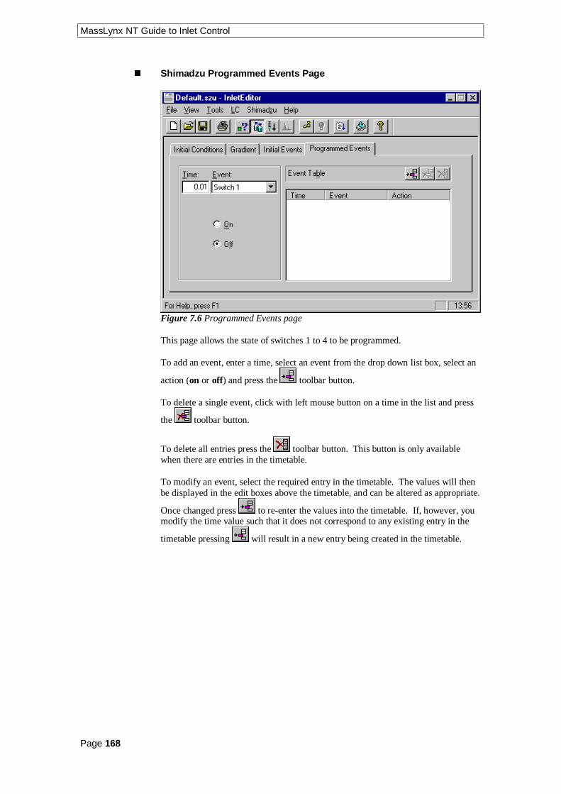
MassLynx NT Guide to Inlet Control
Page 168
n Shimadzu Programmed Events Page
Figure 7.6 Programmed Events page
This page allows the state of switches 1 to 4 to be programmed.
To add an event, enter a time, select an event from the drop down list box, select an
action (on or off) and press the toolbar button.
To delete a single event, click with left mouse button on a time in the list and press
the toolbar button.
To delete all entries press the toolbar button. This button is only availablewhen there are entries in the timetable.
To modify an event, select the required entry in the timetable. The values will thenbe displayed in the edit boxes above the timetable, and can be altered as appropriate.
Once changed press to re-enter the values into the timetable. If, however, youmodify the time value such that it does not correspond to any existing entry in the
timetable pressing will result in a new entry being created in the timetable.

MassLynx NT Guide to Inlet Control
Page 169
Notes................................................................................................................................................................
................................................................................................................................................................
................................................................................................................................................................
................................................................................................................................................................
................................................................................................................................................................
................................................................................................................................................................
................................................................................................................................................................
................................................................................................................................................................
................................................................................................................................................................
................................................................................................................................................................
................................................................................................................................................................
................................................................................................................................................................
................................................................................................................................................................
................................................................................................................................................................
................................................................................................................................................................
................................................................................................................................................................
................................................................................................................................................................
................................................................................................................................................................
................................................................................................................................................................
................................................................................................................................................................
................................................................................................................................................................
................................................................................................................................................................
................................................................................................................................................................
................................................................................................................................................................
................................................................................................................................................................
................................................................................................................................................................
................................................................................................................................................................

MassLynx NT Guide to Inlet Control
Page 170
Notes................................................................................................................................................................
................................................................................................................................................................
................................................................................................................................................................
................................................................................................................................................................
................................................................................................................................................................
................................................................................................................................................................
................................................................................................................................................................
................................................................................................................................................................
................................................................................................................................................................
................................................................................................................................................................
................................................................................................................................................................
................................................................................................................................................................
................................................................................................................................................................
................................................................................................................................................................
................................................................................................................................................................
................................................................................................................................................................
................................................................................................................................................................
................................................................................................................................................................
................................................................................................................................................................
................................................................................................................................................................
................................................................................................................................................................
................................................................................................................................................................
................................................................................................................................................................
................................................................................................................................................................
................................................................................................................................................................
................................................................................................................................................................
................................................................................................................................................................

MassLynx NT Guide to Inlet Control
Page 171
CTC, Cetac and Other SystemsChapter 8
CTC A200S Autosampler
These pages are used to set parameters specific to the Sampler, to access them select
CTCA200S AutoSampler from the View menu or press the toolbar button.
n CTC A200S Status Page
Figure 8.1 CTC A200S Status page
The Fault, Running and Ready indicators at the left side of the screen giveinformation on the current status of the autosampler.
Indicator Red Green
Fault Fault with the autosampler No fault
Running Not running Running
Ready Not ready Ready

MassLynx NT Guide to Inlet Control
Page 172
Vial Enter the number of the vial to take the sample from, for a single injection.Note: When samples are acquired from the Sample List the number on the SampleList overrides this value.
Press the button to download the parameters to the LC system.
Pressing the button or choosing Load Method from the LC or CTC200 menuwill perform the same action.
Press the button to run a single injection. Pressing the button orchoosing Run Method from the LC or CTC200 menu will perform the sameaction.
n CTC A200S Parameters Page
Figure 8.2 CTC A200S Parameters page
Sample Volume Enter the volume of sample (in microliters) to inject.
Air Volume Enter the volume of air (in microliters) to be drawn into the needlebefore the sample, to separate it from the previous sample.
Pull-up Volume Enter the volume of sample (in microliters) to draw into theneedle for a sample wash.
Sample Washes Enter the number of times to wash the needle with sample.
Solvent Washes Pre Injection Enter the number of solvent washes to performusing solvent from reservoirs A and/or B, before an injection.
Solvent Washes Post Injection Enter the number of solvent washes to performusing solvent from reservoirs A and/or B, after an injection.
Pull-up Count Enter the number of times to pull up the Pull-up volume for asample wash.

MassLynx NT Guide to Inlet Control
Page 173
Pull-up Speed Enter the speed (in microliters per second) to pull up the Pull-upvolume for a sample wash.
Pull-up Delay Enter the time to wait between each pull up.
Injection Speed Enter the speed (in microliters per second) to inject the sample.
Pre Injection Delay Enter the time to wait (in seconds) between the needle beinginjected and the plunger being depressed.
Pre Injection Delay Enter the time to wait (in seconds) for the plunger to bedrawn back after an injection.

MassLynx NT Guide to Inlet Control
Page 174
CTC PAL Autosampler
These pages are used to set parameters specific to the Sampler, to access them select
PAL_CC AutoSampler from the View menu or press the toolbar button.When the autosampler parameters are selected the following message is displayed.
Figure 8.3 Error message
This refers to the Macro Editor, which is not part of the standard Cycle Composersoftware, see the PAL Cycle Composer User Manual for details. Press the Cancelbutton to proceed.
When the software is installed a series of files are copied to the default.pro/Acqudbdirectory (*.pma and *.pol).
When the autosampler page is selected the software looks for the presence of thePAL autosampler. If one is found information is read from the Latest_pal.pol file.
To create method editor files when not connected to a PAL copy the Offline_pal.polfile to the Acqudb directory of the required project. When complete, copy theMethod files (*.ccp) to the Acqudb directory of the required project on theacquisition PC.

MassLynx NT Guide to Inlet Control
Page 175
PAL Cycle Composer Method Editor
Figure 8.4 Pal Cycle Composer Method Editor dialog
n To Create a Method (CTC PAL)
1. Select New Method from the File menu. The Choose name of new Methoddialog is displayed.
Figure 8.5 Choose name of new Method dialog
2. Enter the name for the method and press OK.
3. Enter a description of the method in the Method Description box.
4. Select the size of the syringe installed from the Method Syringe drop downlist box.
Note: The syringe size should be defined before any macros are selected asdifferent default values and ranges are defined for each syringe size.Changing the syringe size after selecting macros could result in the valuesentered being outside the ranges allowed and so the macro values will have tobe adjusted.
5. Select a macro from the Selected Macro drop down list box. The parametersrequired for the macro are displayed below the selected macro box.
Note: Placing the cursor on the macro name will display a short descriptionof the macro function, as in Figure 8.6.

MassLynx NT Guide to Inlet Control
Page 176
Figure 8.6 Macro description
Placing the cursor on a field will display a description of the valid values forthis field, as in Figure 8.7.
Figure 8.7 Macro description
6. When the parameters for the macro have been entered press the Insert buttonand the macro will be added to end of the list in the Method MacroSequence box.
To replace a macro, click with the left mouse button on the macro in theMethod Macro Sequence box, select the macro to replace it with, define therequired values and press the Replace button.
To remove a macro from the list, click with the left mouse button on themacro in the Method Macro Sequence box and press the Delete button.
7. Select Save Method or Save Method As from the File menu. The SaveMethod dialog is displayed with the name defaulted to that entered in step 2.The name can be changed if required, any changes made will be reflected inthe Method Name in the editor. Press the OK button to save the method.
Figure 8.8 Save Method dialog
8. The method file (*.ccp) is stored in the Acqudb directory of the currentproject.

MassLynx NT Guide to Inlet Control
Page 177
n To Modify a Method (CTC PAL)
1. Select the method required from the Method Name drop down list box. Themethod files (*.ccp) displayed are those stored in the Acqudb directory of thecurrent project.
2. Click with the left mouse button on the required macro in the Method MacroSequence list and change the parameters displayed on the right of the dialog.
Note: If the syringe size is changed macro values will have to be adjusted asdifferent syringe sizes have different field values.
3. To add a macro, select the macro from the Selected Macro drop down listbox. The parameters required for the macro are displayed below the selectedmacro box.
When the parameters for the macro have been entered press the Insert buttonand the macro will be added to end of the list in the Method MacroSequence box.
To replace a macro, click on the macro in the Method Macro Sequence box,select the macro to replace it with, define the required values and press theReplace button.
To remove a macro from the list, click on the macro in the Method MacroSequence box and press the Delete button.
4. Select Save Method or Save Method As from the File menu. The SaveMethod dialog is displayed with the name defaulted to that entered in step 2.The name can be changed if required, any changes made will be reflected inthe Method Name in the editor. Press the OK button to save the method.
Figure 8.9 Save Method dialog
5. The method file (*.ccp) is stored in the Acqudb directory of the currentproject.
n To Delete a Method (CTC PAL)
1. Select the method required from the Method Name drop down list box.
2. Select Delete Method from the File menu and press Yes on the confirmationdialog.
Note: Methods can also be deleted using Window Explorer. Method files(*.ccp) are stored in the Acqudb directory of the current project.

MassLynx NT Guide to Inlet Control
Page 178
n Sample List Vial Referencing (CTC PAL)
For the CTC PAL autosampler the default Sample List vial referencing for a 96 wellplate in Stack 1 is
Stk1-01:1 to 96 for the first tray in stack 1
Stk1-02:1 to 96 for the second tray in stack 1 etc.
I.e. Stk1-01:1 is entered in the SAMPLE_LOCATION (Bottle) column of theSample List. To use the normal MassLynx referencing 1:1, 1:2, 2:1 etc. the trayshave to be renamed. See page 179 for details.
Note: For OpenLynx the 1:1 tray:vial referencing must be used.

MassLynx NT Guide to Inlet Control
Page 179
Using the PAL CTC Autosampler with OpenLynx
When using the CTC PAL autosampler with OpenLynx the tray names must bedefined numerically and in sequence.
Note: It is recommended that MassLynx is closed down whilst changes are made tothe tray numbering. When MassLynx is restarted the changes will be picked upautomatically.
n To Rename Trays (CTC PAL)
Using the hand held controller, check the order of the tray holders.
Using the hand held controller, number the trays for the tray holders sequentiallystarting from 1.
E.g. if the tray holders are in the order:
Stack1
THldr1
Then the trays should be numbered starting at 1 for the first tray in stack 1 andcontinuing sequentially for THdr1 trays (see the example in Table 8.1 ).
Tray Holder Tray Type Default Tray Name OpenLynx Tray Name
Stack1 MT96 Stk-01 1
Stack1 MT96 Stk-02 2
Stack1 MT96 Stk-03 3
Stack1 MT96 Stk-04 4
Stack1 MT96 Stk-05 5
Stack1 MT96 Stk-06 6
Stack1 MT96 Stk-07 7
Stack1 MT96 Stk-08 8
Stack1 MT96 Stk-09 9
Stack1 MT96 Stk-010 10
Stack1 MT96 Stk-011 11
Stack1 MT96 Stk-012 12
THldr1 VT98 THldr-01 13
THldr1 VT78 THdlr-02 14
Table 8.1 OpenLynx Tray Naming

MassLynx NT Guide to Inlet Control
Page 180
To check that trays are numbered correctly select OpenLynx Plate Login from theInlet Editor, Plate Login menu.
If the trays are correctly numbered then the dialog will appear as in Figure 8.10. Ifthe numbering is incorrect i.e. trays for THdlr1 are numbered from 1 then the dialogwill appear as in Figure 8.11.
Figure 8.10 OpenLynx Plate Login dialog
Figure 8.11 OpenLynx Plate Login dialog
n Using Plates for OpenLynx Plate Login (CTC PAL)
Select OpenLynx Plate Login from the Inlet Editor, Plate Login menu.
If a plate is labelled Disabled it can be used for single shot login. If a plate islabelled Enabled it can be used for plate login. To change the state double click onthe tray number.

MassLynx NT Guide to Inlet Control
Page 181
Cetac ASX100 Autosampler
Figure 8.12 Cetac ASX100 Setup dialog
Technical details of this autosampler are to be found in the manual supplied with theCetac ASX 100 autosampler.
Vial Number Enter the number of the vial to take the sample from. Note: Whensamples are acquired from the Sample List the number on the Sample List overridesthis value.
Standard Tube Check this box if standard vials are being used. The rack codessection will be grayed out and vial number can only be 2 to 14.
Uptake Time Enter the time in seconds for the sample to travel from the samplevial to the Mass Spectrometer.
Before Sample Check this box to rinse the needle before each sample.
Rinse Time Enter the time in seconds required to rinse the needle.
Rack Codes Click with the left mouse button on the code required for the rack.

MassLynx NT Guide to Inlet Control
Page 182
Cetac ASX500 Autosampler
Figure 8.13 Cetac ASX500 Setup dialog
Technical details of this autosampler are to be found in the manual supplied with theCetac ASX 500 autosampler.
Vial Number Enter the number of the vial to take the sample from. Note: Whensamples are acquired from the Sample List the number on the Sample List overridesthis value.
Standard Tube Check this box if standard tubing is being used. The rack codessection will be grayed out and vial number can only be 1 to 10.
Sipper Depth Enter the depth in millimeters the needle should travel to.
Note: The default probe sampling depth is measured from the neck of the tube tothe tip of the probe.
Uptake Time Enter the time in seconds for the sample to travel from the tubing tothe Mass Spectrometer.
Rack Codes Click with the left mouse button on the code required for each rack.
Rinse Before Sample Check this box to rinse the needle before each sample.
Rinse Time Enter the time in seconds required to rinse the needle.

MassLynx NT Guide to Inlet Control
Page 183
Solids Probe
The temperature of a solids probe can be controlled during an acquisition. To dothis you must set a ramp that defines the temperature of the probe tip againstretention time. The ramp can have up to 5 ’segments’ which each have a starttemperature, a time for which the probe will be held at that temperature, and a rate atwhich the probe will be heated to reach the start temperature of the next rampsegment (if there is one).
In addition to these controls, TIC (Total Ion Current) control of the probe is alsoavailable. If TIC control is selected then the TIC value is monitored during theacquisition and that information is used to modify the programmed ramp in such away that the system attempts to keep the TIC at or below the ’Maximum TIC’ value.This feature is very useful as it stops samples from being ’burnt off’ the probeprematurely.
The actual temperature ramp used can be stored with the data file and a remotecontact closure can be used to start the ramp. The External Contact Start boxshould be checked when a robotic probe system is being used.
n To Change probe control parameters (Solids Probe)
1. Choose Inlet from the Acquisition Control Panel Methods menu
-or-
Double click on the probe icon on the Acquisition Control Panel to bring upthe solids probe editor shown below.
2. Make any changes to the parameters.
3. Save the method using either Save or Save As from the File menu.
Figure 8.14 Solids Probe Control Editor

MassLynx NT Guide to Inlet Control
Page 184
n Programming the temperature ramp (Solids Probe)
The probe temperature ramp can be programmed using the keyboard or by draggingthe small red handles on the picture of the ramp itself.
n Using TIC Control (Solids Probe)
To use the TIC control feature you must first check the TIC Control box, whichwill enable the values in the TIC control group to be modified. There are 3 valuesthat you then need to set.
Minimum sets the value for the TIC above which the probe ramping is reduced. Ifthe actual TIC seen from the instrument is below this value, the full heating rate, asprogrammed into the temperature ramp is used to heat the probe. As the TIC risesabove this value, the heating rate is linearly adjusted down based on the differencebetween this minimum value and the maximum value discussed next. For example,a TIC value exactly between the maximum and minimum values would give a 50%rate compared to that requested by the ramp parameters.
Maximum sets the value for the TIC at which the probe ramping is suspended.This is done because the system is trying to keep the TIC at this level and furtherheating would cause it to rise above it. If the TIC reaches this level, heating will notrecommence until it falls back down below.
Finish sets a value for the TIC below which the acquisition of data will terminate.The temperature program will continue however to allow any remaining sample tobe burnt off.
DCI Probe
A DCI probe can be controlled in the same way as a solids probe, as describedabove with the exception that the ramp is programmed for Current rather thantemperature and the DCI current can be stored with the data file, not the probetemperature.
Thermospray Probe
A thermospray probe can be controlled in the same way as a solids probe, asdescribed above, with the exception that the thermospray nozzle temperature can bestored instead of the probe temperature.
RoboProbe
A robotic probe system can be used in conjunction with a CE Instruments A200Sauto injector, or a Zymark laboratory robot.
n CE Instruments A200S
If the A200S is used then setting it up is done as described earlier.

MassLynx NT Guide to Inlet Control
Page 185
n Zymark Labmate
The Zymark setup editor allows you to select a solvent for your sample.
1. Choose Inlet from the Acquisition Control Panel Methods menu
or
Double click on the Picture of the auto injector on the Acquisition ControlPanel to bring up the Zymark editor shown below.
2. Make any changes to the parameters.
3. Save the method using either Save or Save As... from the File menu.
Figure 8.15 Zymark Solvent Selection Editor
Contact Closure
Contact closure is a common method of providing start/stop control of an externalinlet system. Many chromatographs, both LC and GC support contact closurebecause it is often used to provide control of an integrator unit. MassLynx usesessentially the same method of synchronisation for acquiring data, the massspectrometer’s control unit using the start and stop signals produced by thechromatography system to start and stop data acquisition.

MassLynx NT Guide to Inlet Control
Page 186

MassLynx NT Guide to Inlet Control
Page 187
Notes................................................................................................................................................................
................................................................................................................................................................
................................................................................................................................................................
................................................................................................................................................................
................................................................................................................................................................
................................................................................................................................................................
................................................................................................................................................................
................................................................................................................................................................
................................................................................................................................................................
................................................................................................................................................................
................................................................................................................................................................
................................................................................................................................................................
................................................................................................................................................................
................................................................................................................................................................
................................................................................................................................................................
................................................................................................................................................................
................................................................................................................................................................
................................................................................................................................................................
................................................................................................................................................................
................................................................................................................................................................
................................................................................................................................................................
................................................................................................................................................................
................................................................................................................................................................
................................................................................................................................................................
................................................................................................................................................................
................................................................................................................................................................
................................................................................................................................................................

MassLynx NT Guide to Inlet Control
Page 188
Notes................................................................................................................................................................
................................................................................................................................................................
................................................................................................................................................................
................................................................................................................................................................
................................................................................................................................................................
................................................................................................................................................................
................................................................................................................................................................
................................................................................................................................................................
................................................................................................................................................................
................................................................................................................................................................
................................................................................................................................................................
................................................................................................................................................................
................................................................................................................................................................
................................................................................................................................................................
................................................................................................................................................................
................................................................................................................................................................
................................................................................................................................................................
................................................................................................................................................................
................................................................................................................................................................
................................................................................................................................................................
................................................................................................................................................................
................................................................................................................................................................
................................................................................................................................................................
................................................................................................................................................................
................................................................................................................................................................
................................................................................................................................................................
................................................................................................................................................................

MassLynx NT Guide to Inlet Control
Page 189
Index
A
AS800, 94
C
CE Instruments, 91Cetac ASX100 Autosampler, 181Cetac ASX500 Autosampler, 182Contact Closure, 185CTC PAL Autosampler, 174
Using with OpenLynx, 179CTC, Cetac and Other Systems, 171CTCA200S Autosampler, 171
D
DCI Probe, 184
G
GC8000, 91GC8000 DPFC option, 92Gilson Autosamplers, 97
Adjusting the Arm Height on aGilson 215, 115Bed Layout Editor, 112Configuration Pages, 98Multi-Injector Parameters, 104Plate Generator, 109Supported Models, 97Tray Options, 108
Gilson Pump, 118Pump Configuration, 121
Gilson Systems, 97GPIB Communication, 7
H
Hewlett Packard Systems, 125HP 7673A, 127HP Diode Array Detectors, 133HP UV Detectors, 134, 135, 136HP1050, 128HP1090, 128HP1100, 128HP5890, 125HP6890, 137HP6890 Autosampler, 138, 151HP6890 Communication Parameters,152HP6890 Pump, 140HP6890 Toolbar, 153HPIB Communication, 7
I
Inlet Configuration, 6Inlet Editor, 2Inlet Editor Toolbar, 3Inlet Systems, 1
J
Jasco 1500 Autosampler, 157Jasco 1500 Pump, 158Jasco 1500 UV Detector, 160Jasco 900 Autosampler, 157Jasco 900 Pump, 158Jasco 900 UV Detector, 160Jasco Systems, 157
R
RoboProbe, 184
S
Shimadzu Autosampler, 163Shimadzu Pump, 165Shimadzu Pump ConfigurationParameters, 164Shimadzu Systems, 163Solids Probe, 183System Status Page, 4
T
Thermospray Probe, 184
W
Waters 2487 UV Detector, 27, 28Waters 2690 Autosampler, 15Waters 2690 Pump, 17Waters 2700 Autosampler, 30Waters 2790 Autosampler, 40Waters 2790 Pump, 44Waters 486 UV Detector, 26Waters 600 Pump, 11Waters 996 PDA Detector, 23Waters CapLC Autosampler, 71Waters CapLC PDA Detector, 81Waters CapLC Pump, 63Waters CapLC System StatusPages, 60Waters SAT/IN PDA Detector, 29Waters Systems, 11

MassLynx NT Guide to Inlet Control
Page 190


