MASTECH® MS6813 Multi Function Network Cable Tester Users Manual Table of Contents LIMITED WARRANTY AND LIMITATION OF LIABILITY .................................................................. 1 Out of Box ....................................................................................................................................................... 2 Safety Information ........................................................................................................................................ 2 Using the Tester ............................................................................................................................................. 3 1. INTRODUCTION .................................................................................................................... 4 1.1 MS6813 Features ..................................................................................................................... 4 1.2 Components and Buttons ...................................................................................................... 5 2. USING THE TESTER................................................................................................................ 8 2.1 Network Cable Testing ........................................................................................................... 8 2.1.1 Error Indicator ............................................................................................................................. 8 2.1.2 Test Mode....................................................................................................................................... 9 2.1.3 Debug Mode ...............................................................................................................................10 2.2 Coaxial Cable Testing ...........................................................................................................11 2.3 Continuity Testing .................................................................................................................11
Transcript
MASTECH®
MS6813
Multi Function Network Cable Tester
Users Manual
Table of Contents
LIMITED WARRANTY AND LIMITATION OF LIABILITY .................................................................. 1
Out of Box ....................................................................................................................................................... 2
Safety Information ........................................................................................................................................ 2
Using the Tester ............................................................................................................................................. 3
2.1.2 Test Mode....................................................................................................................................... 9
4. CONTACT MASTECH ............................................ ERROR! BOOKMARK NOT DEFINED.
Thank you for purchasing Mastech MS6813 Multi Function Network Cable Tester. Please
read the Users Manual carefully to be familiar with the Tester. For more information,
please visit our website at http://www.mastech.cn.
TO AVOID POSSIBLE ELECTRIC SHOCK OR PERSONAL INJURY:
Use the Tester only as specified in this manual or the protection provided by the Tester
might be impaired.
Do not place the Tester near explosive gas or vapor.
Read the Users Manual before use and follow all safety instructions.
LIMITED WARRANTY AND LIMITATION OF LIABILITY
This MS6813 product from Mastech will be free from defects in material and
workmanship for one year from the date of purchase. This warranty does not cover fuses,
disposable batteries, or damage from accident, neglect, misuse, alteration, contamination, or
abnormal conditions of operation or handling. Resellers are not authorized to extend any
other warranty on Mastech’s behalf. To obtain service during the warranty period, contact
your nearest Mastech authorized service center to obtain return authorization information,
then send the product to that Service Center with a description of the problem.
Mastech MS6813 Multi Function Network Cable Tester
2
Out of Box
Check the Tester and accessories thoroughly before using the Tester. Contact your local
distributor if the Tester or any components are damaged or malfunction.
Accessories
One Users Manual
1 9V 6F22 Battery
Safety Information
WARNING
TO REDUCE THE RISK OF FIRE, ELECTRICAL SHOCK, PRODUCT DAMAGE OR PERSONAL INJURY, PLEASE FOLLOW THE SAFETY INSTRUCTIONS DESCRIBED IN THE USER MANUAL. READ THE USER MANUALS BEFORE USING THE TESTER.
WARNING
DO NOT PLACE THE TESTER IN ANY ENVIRONMENT OF HIGH PRESSURE, HIGH TEMPERATURE, DUST, EXPLOSIVE GAS OR VAPOR. TO ENSURE SAFE OPERATION AND LIFE OF THE TESTER, FOLLOW THESE INSTRUCTIONS
Safety Symbols
Important safety message
Conforms to relevant European Union directives
Mastech MS6813 Multi Function Network Cable Tester
3
Warning Symbols
Warning Risk of danger. Important information. See Users Manual
Caution Statement identifies conditions and actions that fail to follow the
instructions could result false reading, damage the Tester or the
equipment under test.
Using the Tester
WARNING
TO AVOID ELECTRICAL SHOCK AND INJURY, COVER THE TESTER WITH PROTECTIVE COVER WHEN NOT IN USE.
Caution 1. Operate the Tester between 0~50°C (32~122°F).
2. Avoid shaking, dropping or taking any kind of impacts when
using or transporting the Tester.
3. To avoid possible electric shock or personal injury, repairs or servicing not covered in this
manual should be performed only by qualified personnel.
4. Check the terminals every time before operate the Tester. Do not operate the Tester if the
terminals are damaged or one or more functions are not working properly.
5. Avoid exploring the Tester to direct sunlight to ensure and extend the life of the Tester.
6. Do not place the Tester in strong magnetic field, it may cause false readings.
7. Use only the batteries indicated in the Technical Spec.
8. Avoid exploring the battery to humidity. Replace the batteries as soon as the low battery
indicator appears.
9. Sensitivity of the Tester toward temperature and humidity will be lower over time. Please
calibrate the Tester periodically for best performance
10. Please keep the original packing for future shipping purpose (ex. Calibration)
Mastech MS6813 Multi Function Network Cable Tester
4
1,Introduction
MS6813 is a hand held network cable tester, ideal for Coaxial Cable (BNC), UTP and STP
Cable installation, measurement, maintenance or inspection. It also offers a fast and
convenient way of testing telephone line modes, greatly simplifies telephone line installation
and maintenance.
1.1 MS6813 Features
Self implement T568A, T568B, 10Base-T and Token Ring cables testing.
UTP and STP co-axial cable testing.
Network integrity and configuration examination.
Open/ shorts circuit, miss wiring, reversals, and split pairs testing.
Network Continuity testing.
Cable open/short point tracing.
Receive signals in the network or telephone cable.
Transmitting signal to target network and tracing cable direction.
Detect telephone line modes : ideal, vibrate, or in used (off-hook)
Mastech MS6813 Multi Function Network Cable Tester
5
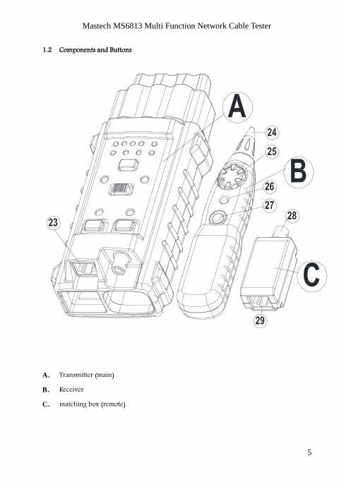
1.2 Components and Buttons
A. Transmitter (main)
B. Receiver
C. matching box (remote)
Mastech MS6813 Multi Function Network Cable Tester
6
Mastech MS6813 Multi Function Network Cable Tester
7
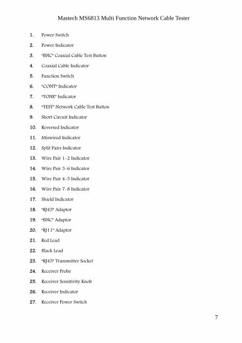
1. Power Switch
2. Power Indicator
3. “BNC” Coaxial Cable Test Button
4. Coaxial Cable Indicator
5. Function Switch
6. “CONT” Indicator
7. “TONE” Indicator
8. “TEST” Network Cable Test Button
9. Short Circuit Indicator
10. Reversed Indicator
11. Miswired Indicator
12. Split Pairs Indicator
13. Wire Pair 1-2 Indicator
14. Wire Pair 3-6 Indicator
15. Wire Pair 4-5 Indicator
16. Wire Pair 7-8 Indicator
17. Shield Indicator
18. “RJ45” Adaptor
19. “BNC” Adaptor
20. “RJ11” Adaptor
21. Red Lead
22. Black Lead
23. “RJ45” Transmitter Socket
24. Receiver Probe
25. Receiver Sensitivity Knob
26. Receiver Indicator
27. Receiver Power Switch
Mastech MS6813 Multi Function Network Cable Tester
8
28. Remote “BNC” Socket
29. Remote “RJ45” Socket
1. Using the Tester
1.1 Network Cable Testing
WARNING TO AVOID ELECTRICAL SHOCK AND INJURY, UNPOWER THE CIRCUIT WHILE
PERFORMING TESTS
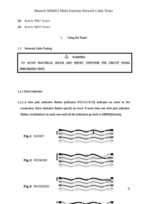
1.1.1 Error Indicator
1.1.2 A wire pair indicator flashes (indicator #13,14,15,16) indicates an error in the
connection. Error indicator flashes specify an error. If more than one wire pair indicator
flashes, troubleshoot on each case until all the indicators go back to GREEN(Normal).
Fig.1 SHORT
Fig.2 MISWIRE
Fig.3 REVERSED
Fig.4 SPLIT PAIRS
Mastech MS6813 Multi Function Network Cable Tester
9
Open Circuit: Open Circuit is not commonly seen and therefore no indication is included in
the Tester. Typically there are 2 to 4 coaxial cables pairs in the network. Corresponding
indicators are off if RJ45 sockets are not connected with coaxial cable pairs. User debugs the
network with the wire pair indicators accordingly.
Short Circuit: shown in Fig.1.
Miswired: shown in Fig. 2: two pairs of wires are connected to wrong terminals.
Reversed: shown in Fig.3: Two wires within the pair are reversely connected to the pins in the
remote.
Split Pairs: shown in Fig.4: Split pairs occurs when the tip (positive conductor) and ring
(negative conductor) of two pairs are twisted and interchanged.
Note:
The Tester only shows one type of error per test. Fix one error first then make sure to perform
the test again to check other possible errors.
Test Mode
Follow the steps:
a) Connect one of the wires to RJ45 transmitter socket.
b) Connect the other end to RJ45 receiver socket.
c) Turn the Tester power on.
d) Press “TEST” button once to start testing.
e) During the test press “TEST” button again to stop testing.
Example: wires pair 1-2 and pair 3-6 are short circuit. In test mode, the error indicators will
show as following:
1-2 and 3-6 indicators flash green lights, short circuit indicator flash red
light.
4-5 indicator shows green lights (no error)
7-8 indicator shows green lights (no error)
Mastech MS6813 Multi Function Network Cable Tester
10
1.1.3 Debug Mode
In Debug Mode, detail of the connection error is displayed. Condition of every pair of wires is
shown twice in order. With the wire pair indicators and error indicators, the network cable
can be indentified and debugged. Follow the steps:
a) Connect one end of wire to RJ45 transmitter socket.
b) Connect the other end of wire to receiver socket.
c) Power on the Tester, power indicator is on.
d) Press and hold “TEST” button until all the wire pairs and error indicators are all
on, release the button afterward.
e) Determine the error from the indicators.
f) If a wire pair indicator turns green twice (one short, one long), and other error
indicators are off, then the wire pair is in good condition.
g) If the wire pair malfunctions, the corresponding indicator will flash once and
then turn on (long) again with the error indicator on.
h) In debugging mode, press and release the “TEST” button to end the debug.
Example: Wire pair 1-2 and pair 3-6 are short circuit. In debug mode indicators will show
as follow:
Wire pair 1-2 flashes green light, wire pair 3-6 indicator and short circuit
indicator flashes red light.
Wire pair 3-6 flashes green light, wire pair 1-2 indicator and short circuit
indicator flashes red light.
4-5 indicator shows green lights (no error)
7-8 indicator shows green lights (no error)
Mastech MS6813 Multi Function Network Cable Tester
11
1.2 Coaxial Cable Testing
WARNING TO AVOID ELECTRICAL SHOCK AND INJURY, UNPOWER THE CIRCUIT WHILE
PERFORMING TESTS.
Follow the steps:
a) Connect one end of coaxial cable to transmitter BNC socket, another end to
remote BNC socket.
b) Power on the Tester, power indicator is on.
c) BNC indicator should be off. If the light is on, the network is miswired.
d) Press “BNC” button on the transmitter, if coaxial cable indicator display green
light, the network connection in good condition, if the indicator display red light,
the network is miswired.
e) Continuity Testing
WARNING TO AVOID ELECTRICAL SHOCK AND INJURY, UNPOWER THE CIRCUIT WHILE
PERFORMING TESTS.
a) Use function “CONT” on the transmitter to do the testing (to test both ends of cable
simultaneously). Turn the switch on the transmitter to “CONT” position; connect red
lead on the transmitter to one end of the target cable and black lead to the other end. If
the CONT indicator display red light, the cable continuity is in good condition.
(Network resistance lower then 10KΩ )
b) Use “TONE” function on the transmitter along with the receiver (when both ends of
network cables are not copresent.) Connect the wire adaptor on transmitter to the
Mastech MS6813 Multi Function Network Cable Tester
12
network. Turn the switch to “TONE” mode and the “TONE” indicator turns red. Move
the receiver antenna close the target network cable, press and hold the power button
on the receiver. Adjust receiver volume through sensitivity switch. Network is well
connected if the receiver makes buzz sound.
1.3 Network Cable Tracking
WARNING TO AVOID ELECTRICAL SHOCK AND INJURY, DO NOT CONNECT RECEIVER TO ANY
AC SIGNAL LARGER THEN 24V.
2.3.1 Sending Audio Frequency Signal:
Connect both leads(“RJ45” Adaptor、“BNC” Adaptor、“RJ11” Adaptor、the red lead and
back lead) on the transmitter to the network cable (or connect the red lead to target
cable and black lead to ground depends on the circuit). Turn the transmitter switch to
“TONE” mode and the indicator will lights up. Press and hold receiver power button,
move the receiver close to the target network to receive signal. Adjust receiver volume
through sensitivity switch.
2.3.2 Tracking Network Cable
Use “TONE” mode on transmitter along with the receiver to track cable. Connect the wire
adaptor to the target network (or connect the red lead to target cable and black lead to
ground depends on the circuit). Switch to “TONE” mode on the transmitter, “TONE” indicator
turns on. Press and hold the power button on the receiver. Move the receiver near the target
network to receive audio frequency signal. The Tester detects the direction and continuity of
the network cable. Adjust receiver volume through sensitivity switch.
Mastech MS6813 Multi Function Network Cable Tester
13
2.5 Telephone Line Modes Testing
2.5.1 Differentiate TIP or RING wire:
Turn the switch on the transmitter to “OFF”, connect the corresponding wire adaptor to the
open telephone lines in the network. If,
a) “CONT” indicator turns green, the red lead on the transmitter connects to RING of
the telephone line.
b) “CONT” indicator turns red, the red lead on the transmitter connects to TIP of the
telephone line.
2.5.2 Determine Idle, Vibrate or in use (off-hook):
Turn the switch on the transmitter to “OFF” mode. When the target telephone line is at work,
connect the red lead to RING line and the black lead to TIP line, If,
a) “CONT” indicator turns green, the telephone line is idle.
b) “CONT” indicator stays off, the telephone line is off-hook.
c) “CONT” indicator turns green along with periodic red flash, the telephone line is
in vibrate mode.
d) When connect receiver antenna to an explored telephone wire, press and hold
the receiver power button to receive the audio signal.
2. Maintenance and Repair
2.1 Battery Replacement
Replace new batteries when the battery indicator is on, remove the battery cover in the back