DANGER! Take precautions to ensure that all fuel components are away from heat sources, such as the engine or exhaust pipes. A fire or explosion hazard could cause serious injury or death! DANGER! Before disconnecting or removing fuel lines, ensure the engine is cold. Do not smoke. Extinguish all open flames. An open flame, spark, or extreme heat near gasoline can result in a fire or explosion causing property damage, serious injury, and/or death. DANGER! Never get under a vehicle supported only by a jack. Serious injury or death can result from vehicles falling off of jacks. Before working underneath a vehicle, support it solidly with jack stands. Parts Identification 1 2 3 4 5 6 7 8 9 10 11 Fuel Pump and Filter Installation The following section covers the installation of the in-line pump as well as the pre and post filters. The fuel pump MUST be mounted lower than the lowest part of the fuel tank, and as close to the tank as possible. The fuel tank must also be properly vented. 1. Use Figure 1 below as a reference for the orientation and location of the fuel system components: 1 Walbro 255 LPH Fuel Pump Master Kit for Holley Sniper and FiTech EFI Systems
Transcript
www.holley.com 4 1-866-464-6553
MASTER KIT FUEL SYSTEM INSTALLATION DANGER! Take precautions to ensure that all fuel components are away from heat sources, such as the engine or exhaust
pipes. A fire or explosion hazard could cause serious injury or death! DANGER! Before disconnecting or removing fuel lines, ensure the engine is cold. Do not smoke. Extinguish all open
flames. An open flame, spark, or extreme heat near gasoline can result in a fire or explosion causing property damage, serious injury, and/or death.
DANGER! Never get under a vehicle supported only by a jack. Serious injury or death can result from vehicles falling off of
jacks. Before working underneath a vehicle, support it solidly with jack stands.
6 7 8 9 10 11 Fuel Pump and Filter Installation The following section covers the installation of the in-line pump as well as the pre and post filters. The fuel pump MUST be mounted lower than the lowest part of the fuel tank, and as close to the tank as possible. The fuel tank must also be properly vented. 1. Use Figure 1 below as a reference for the orientation and location of the fuel system components:
1
Walbro 255 LPH Fuel Pump Master Kit for Holley Sniper and FiTech EFI Systems
Figure 1 2. Mount the electric fuel pump as close to the fuel tank outlet as possible with the bracket provided. Mounting the fuel pump in this
manner will insure that the pump will prime easily to ensure faster starts. 3. There are two filters included with this kit. The pre-filter (Item 5) MUST be installed between the fuel tank and the fuel pump inlet
(unless an in-tank pump is used in place of the pump in this kit). The purpose of this filter is to protect the fuel pump from particles of dirt or other foreign material. The filter should be installed with the arrow on the filter pointing in the direction of the fuel flow.
4. The post-fuel filter (Item 4) should be installed between the electric pump outlet and TBI unit. This is a 10 micron EFI filter. Position the filter, so the fuel hoses can be routed without kinks or sharp bends. The filter should be installed with the arrow on the filter pointing in the direction of the fuel flow (Figure 2).
Figure 2
WARNING! Ensure both filters are installed in the proper direction. A flow direction arrow is printed on the side of the filter
to indicate the direction of fuel flow. Failure to do so will result in a system malfunction.
Return Line Bulkhead Fitting Installation The Sniper EFI system requires a return fuel line to the fuel tank. This kit includes the hose and fittings necessary for a return line installation on most vehicles. Some late model vehicles that were originally equipped with a throttle body injection system may already have a return line to the fuel tank that can be utilized. The return line must not present a pressure restriction to the return fuel flow. There should never be more than approximately 3 PSI of pressure in the return line. A line that is too small, or has restrictions will cause tuning problems with the system. DANGER! Do not use the vapor canister lines as a fuel return line. Possible fuel leaks may create a fire or explosion hazard,
causing serious injury or death. DANGER! Proper installation of the fuel return line will necessitate complete removal of the fuel tank. This work should be
done by a fuel tank specialist, who regularly does this work and is familiar with safety regulations and precautions necessary to do this work. If a person attempts this work, who is not familiar with the safety regulations and precautions, an explosion hazard may result causing serious injury or death.
1. Choose an ideal location for the bulkhead fitting to be installed. The fitting must be installed through a flat surface where the
nut can be tightened from the bottom. It must also be installed in a location where the fuel cuff will not interfere with the
sending unit float. If possible, we strongly recommend removing, cleaning, and drilling into the sending unit. The fitting must be oriented as shown below in Figure 3. The item numbers from the parts identification list are referenced.
DANGER! IF DRILLING INTO TANK (RATHER THAN SENDING UNIT), HOLLEY RECOMMENDS HAVING YOUR TANK
PROFESSIONALLY CLEANED BEFORE DRILLING. IF YOU CHOOSE NOT TO HAVE THE TANK PROFESSIONALLY CLEANED, DRAIN THE TANK COMPLETELY, LET DRY, AND FILL WITH WATER.
Figure 3
2. Drill a 9/16” hole and debur. Remove all metal shavings and particles from tank.
3. Install bulkhead fitting with one Stat-O-Seal above the surface, and one below.
4. Screw the bulkhead nut onto fitting from the bottom, inside of the tank. Snug with a wrench. A spare bulkhead nut has been
provided and will not be used in this installation.
5. Insert the barbed end of a straight Vapor Guard hose end (Item 7) into an end of the fuel cuff (Item 8) and ensure the cuff covers both barbs.
6. Slide hose clamp (Item 3) over fuel cuff and fitting and tighten to secure.
7. Screw fuel cuff assembly to bottom of bulkhead nut and snug with a wrench. Ensure bottom of cuff will be submerged in fuel
as shown in Figure 3. Cuff can be trimmed if necessary. Fuel Line Installation With the fuel pump, filters, and bulkhead fitting all in place. You are now ready to install the fuel lines. Some connections will use hose clamps (Item 3), while others will use AN hose ends (Item 7). These connections are noted in Figures 1 & 3. Be sure to read and thoroughly understand all steps, notes, and hose assembly instructions below before proceeding with the fuel line installation. DANGER! Failure to use a fuel hose that meets SAE J30 standards could result in fuel leaks. A fuel leak may result in a fire
or explosion hazard, which could cause serious injury or death. DANGER! Failure to use a steel fuel line that meets SAE J526 standards could result in fuel leaks. A fuel leak may result in a
fire or explosion hazard, which could cause serious injury or death. DANGER! Rigid fuel line tubing should be used for under vehicle runs, such as along vehicle frame rails or under floor pans.
Failure to do so is a potential fire or explosion hazard, which could cause serious injury or death 1. If using steel line, the hose (Item 2) can be used to connect the steel line to the pump and filters. You should not connect a rubber
hose directly to a steel line unless the end of the line has a “bead/nipple” or barb that retains the hose. If the steel line is just cut
off, purchase a compression fitting that a barbed hose end can be installed on, or use a tool to roll a bead/nipple on the end of the steel line.
2. If you plan to install a fuel pressure gauge, do so at this time. The Sniper EFI systems are designed for an operating pressure of 58.5 PSI. Although this is factory pre-set, it is ideal that it be checked.
3. If using the existing fuel lines, inspect and replace any hose, clamps, or fuel line showing ANY sign of aging.
4. Anchor all fuel lines securely to solid chassis members at 1 ½ foot intervals using rubber coated steel clamps (not supplied). Use of
only approved steel fuel line tubing will afford maximum fuel line protection against road hazards and premature wearing due to flexing, temperature extremes, road salt, weather, etc.
Hose Assembly
1. Cut the hose square with a sharp knife or Earls Hand-Held Hose Cutter (D022ERL).
Figure 4
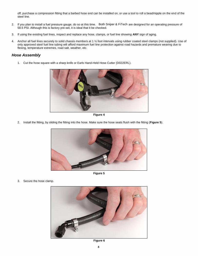
2. Install the fitting, by sliding the fitting into the hose. Make sure the hose seats flush with the fitting (Figure 5).