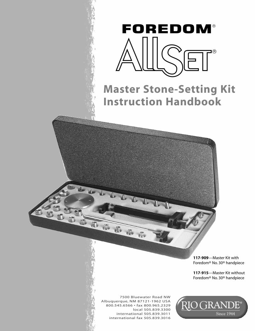
Master Stone-Setting Kit Instruction Handbook 7500 Bluewater Road NW Albuquerque, NM 87121-1962 USA 800.545.6566 • fax 800.965.2329 local 505.839.3300 international 505.839.3011 international fax 505.839.3016 117-909—Master Kit with Foredom® No. 30® handpiece 117-915—Master Kit without Foredom® No. 30® handpiece
Transcript
Master Stone-Setting KitInstruction Handbook
7500 Bluewater Road NWAlbuquerque, NM 87121-1962 USA
800.545.6566 • fax 800.965.2329local 505.839.3300
international 505.839.3011international fax 505.839.3016
117-909—Master Kit with Foredom® No. 30® handpiece
117-915—Master Kit without Foredom® No. 30® handpiece
2
Congratulations on your purchase of the AllSet® Master stone-setting kit. Considered one of the most significant jewelry-industry inventions of the past 25 years, Allset prong-, pavé- and channel-cutting tools,like the ones in this kit, deliver precise, repeatable accuracy and flexibility whenever they’re used. The resultis higher quality, defect-free stone settings done faster and easier than ever before!
Here’s what you’ll find with your Master Stone-Setting kit:
• Non-Rotating Guide Assembly. This lightweight assembly is the heart of the Master kit. It attaches easilyto a Foredom® No. 30® handpiece and includes body, collar, shaft and L-bracket.
• The Easy-Cut Prong Guide. Create level, uniform and precise cuts time after time with this remarkableprong-cutting aid. Its unique design ensures a level and uniform-height cut on square, round or any othershape of prong. It also includes a new stop guide that precisely controls the depth of each cut.
• Channel-Setting Guides. Create perfectly contoured channel settings for round, square and baguettestones quickly and easily with these precision guides. Kit includes three guides (small, large and knife-edge).
• Prong Guides. Ensure the proper-depth cutting of prongs in single- or multiple-prong settings with theseprecise guides. Includes 13 separate guides..
• Pavé Guides. Let you create the cobblestone effect of pavé in half the time it would take by hand. Includesseven stainless steel guides.
• Allset Quality. Allset kits and components are made in the USA of highly durable materials and are versatiletools that stand up to multiple demands and configurations. All of the cutting guides are made of the highest quality stainless steel for a cleaner finish and a long, rust-free life.
MasterStone-Setting Kit
InstructionHandbook
Safety Notes1. Always use eye protection when cutting prongs and channels with your AllSet® Master stone-setting
kit or when using any power tool.2. Some prong- and channel-cutting operations may require close placement of the hands to sharp,
cutting edges. To avoid injury, please pay careful attention to hand placement, avoid distractions anddo not operate prong-cutting equipment without your full attention.
3. For safety and effectiveness with any power tool, maintain a clean work surface and a clean general work area.
3
Introduction
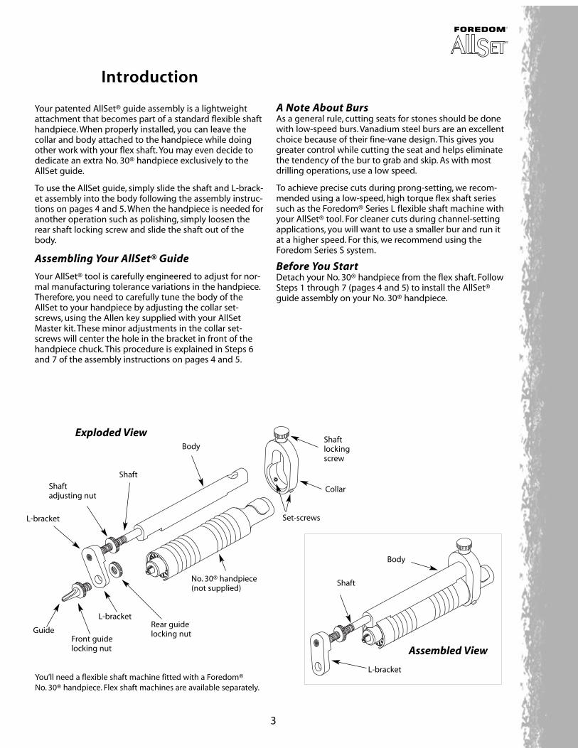
Your patented AllSet® guide assembly is a lightweightattachment that becomes part of a standard flexible shafthandpiece. When properly installed, you can leave the collar and body attached to the handpiece while doingother work with your flex shaft. You may even decide todedicate an extra No. 30® handpiece exclusively to theAllSet guide.
To use the AllSet guide, simply slide the shaft and L-brack-et assembly into the body following the assembly instruc-tions on pages 4 and 5. When the handpiece is needed foranother operation such as polishing, simply loosen therear shaft locking screw and slide the shaft out of thebody.
Assembling Your AllSet® Guide
Your AllSet® tool is carefully engineered to adjust for nor-mal manufacturing tolerance variations in the handpiece.Therefore, you need to carefully tune the body of theAllSet to your handpiece by adjusting the collar set-screws, using the Allen key supplied with your AllSetMaster kit. These minor adjustments in the collar set-screws will center the hole in the bracket in front of thehandpiece chuck. This procedure is explained in Steps 6and 7 of the assembly instructions on pages 4 and 5.
A Note About BursAs a general rule, cutting seats for stones should be donewith low-speed burs. Vanadium steel burs are an excellentchoice because of their fine-vane design. This gives yougreater control while cutting the seat and helps eliminatethe tendency of the bur to grab and skip. As with mostdrilling operations, use a low speed.
To achieve precise cuts during prong-setting, we recom-mended using a low-speed, high torque flex shaft seriessuch as the Foredom® Series L flexible shaft machine withyour AllSet® tool. For cleaner cuts during channel-settingapplications, you will want to use a smaller bur and run itat a higher speed. For this, we recommend using theForedom Series S system.
Before You StartDetach your No. 30® handpiece from the flex shaft. FollowSteps 1 through 7 (pages 4 and 5) to install the AllSet®guide assembly on your No. 30® handpiece.
Body
Shaft
L-bracket
Shaftlockingscrew
Set-screws
No. 30® handpiece(not supplied)
Rear guidelocking nut
L-bracket
Front guidelocking nut
Body
Shaft
L-bracket
Collar
Guide
Shaft adjusting nut
You’ll need a flexible shaft machine fitted with a Foredom® No. 30® handpiece. Flex shaft machines are available separately.
Exploded View
Assembled View
4
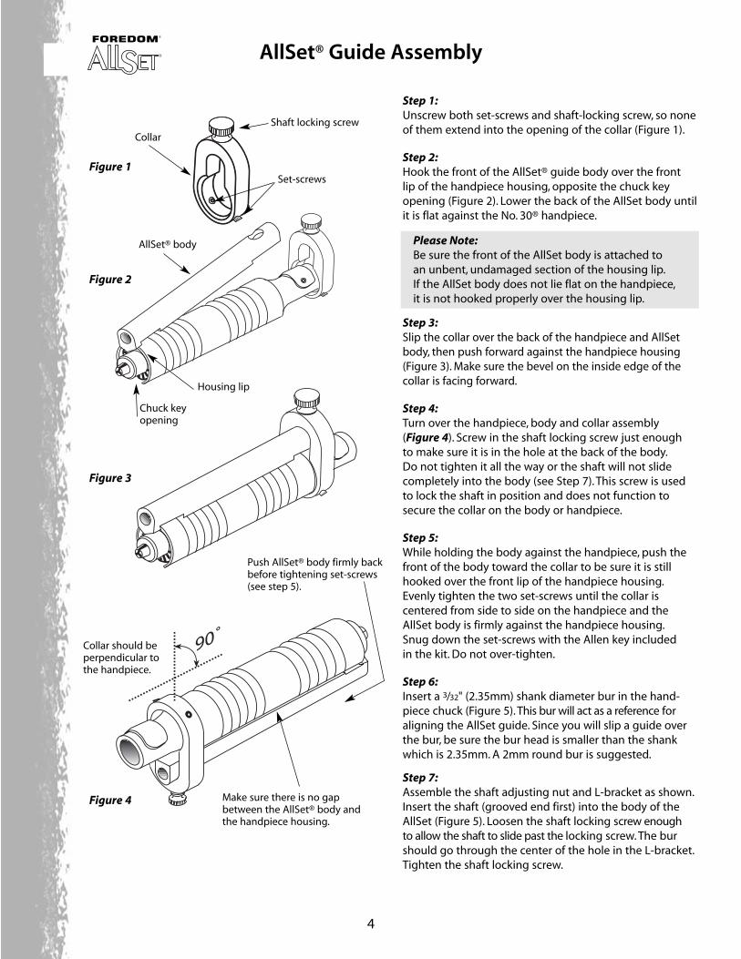
90˚
Push AllSet® body firmly backbefore tightening set-screws(see step 5).
Make sure there is no gapbetween the AllSet® body andthe handpiece housing.
Step 1:Unscrew both set-screws and shaft-locking screw, so noneof them extend into the opening of the collar (Figure 1).
Step 2:Hook the front of the AllSet® guide body over the front lip of the handpiece housing, opposite the chuck keyopening (Figure 2). Lower the back of the AllSet body untilit is flat against the No. 30® handpiece.
Please Note:Be sure the front of the AllSet body is attached toan unbent, undamaged section of the housing lip.If the AllSet body does not lie flat on the handpiece,it is not hooked properly over the housing lip.
Step 3:Slip the collar over the back of the handpiece and AllSetbody, then push forward against the handpiece housing(Figure 3). Make sure the bevel on the inside edge of thecollar is facing forward.
Step 4:Turn over the handpiece, body and collar assembly(Figure 4). Screw in the shaft locking screw just enough to make sure it is in the hole at the back of the body.Do not tighten it all the way or the shaft will not slidecompletely into the body (see Step 7). This screw is usedto lock the shaft in position and does not function tosecure the collar on the body or handpiece.
Step 5:While holding the body against the handpiece, push thefront of the body toward the collar to be sure it is stillhooked over the front lip of the handpiece housing.Evenly tighten the two set-screws until the collar is centered from side to side on the handpiece and theAllSet body is firmly against the handpiece housing.Snug down the set-screws with the Allen key included in the kit. Do not over-tighten.
Step 6:Insert a 3/32" (2.35mm) shank diameter bur in the hand-piece chuck (Figure 5). This bur will act as a reference foraligning the AllSet guide. Since you will slip a guide overthe bur, be sure the bur head is smaller than the shankwhich is 2.35mm. A 2mm round bur is suggested.
Step 7:Assemble the shaft adjusting nut and L-bracket as shown.Insert the shaft (grooved end first) into the body of theAllSet (Figure 5). Loosen the shaft locking screw enough to allow the shaft to slide past the locking screw. The burshould go through the center of the hole in the L-bracket.Tighten the shaft locking screw.
Shaft locking screw
Collar
AllSet® body
Collar should beperpendicular tothe handpiece.
Set-screws
Chuck keyopening
Figure 1
Figure 2
Figure 3
Figure 4
Housing lip
AllSet® Guide Assembly
5
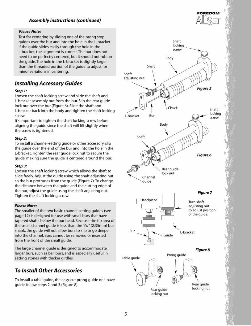
Shaftlockingscrew
Body
Shaftadjusting nut
L-bracket
Shaft
Bur
Chuck
Rear guidelock nut
Handpiece Turn shaftadjusting nut to adjust position of the guide.
Bur
Table guide
Rear guidelocking nutRear guide
locking nut
Prong guide
Figure 5
Figure 6
Figure 7
Figure 8
Shaftlockingscrew
Body
Shaft
Channelguide
GuideL-bracket
Assembly instructions (continued)
Please Note:Test for centering by sliding one of the prong stopguides over the bur and into the hole in the L-bracket.If the guide slides easily through the hole in the L-bracket, the alignment is correct. The bur does not need to be perfectly centered, but it should not rub on the guide. The hole in the L-bracket is slightly larger than the threaded portion of the guide to adjust for minor variations in centering.
Installing Accessory GuidesStep 1:Loosen the shaft locking screw and slide the shaft and L-bracket assembly out from the bur. Slip the rear guidelock nut over the bur (Figure 6). Slide the shaft and L-bracket back into the body and tighten the shaft lockingscrew.It’s important to tighten the shaft locking screw beforealigning the guide since the shaft will lift slightly whenthe screw is tightened.
Step 2:To install a channel-setting guide or other accessory, slipthe guide over the end of the bur and into the hole in theL-bracket. Tighten the rear guide lock nut to secure theguide, making sure the guide is centered around the bur.
Step 3:Loosen the shaft locking screw which allows the shaft toslide freely. Adjust the guide using the shaft adjusting nutso the bur protrudes from the guide (Figure 7). To changethe distance between the guide and the cutting edge ofthe bur, adjust the guide using the shaft adjusting nut.Tighten the shaft locking screw.
Please Note:The smaller of the two basic channel-setting guides (seepage 12) is designed for use with small burs that havetapered shafts below the bur head. Because the tip area ofthe small channel guide is less than the 3/32" (2.35mm) burshank, the guide will not allow burs to slip or go deeperinto the channel. Burs cannot be removed or insertedfrom the front of the small guide.
The large channel guide is designed to accommodatelarger burs, such as ball burs, and is especially useful insetting stones with thicker girdles.
To Install Other Accessories
To install a table guide, the easy-cut prong guide or a pavéguide, follow steps 2 and 3 (Figure 8).
6
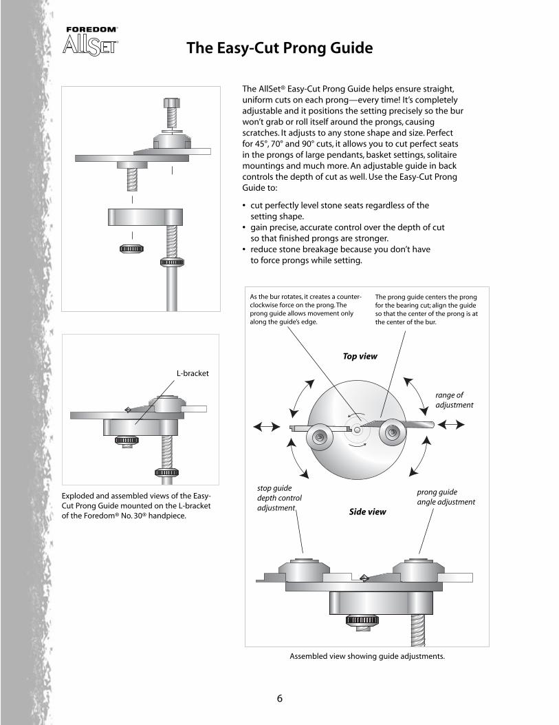
Exploded and assembled views of the Easy-Cut Prong Guide mounted on the L-bracketof the Foredom® No. 30® handpiece.
Assembled view showing guide adjustments.
The AllSet® Easy-Cut Prong Guide helps ensure straight,uniform cuts on each prong—every time! It’s completelyadjustable and it positions the setting precisely so the burwon’t grab or roll itself around the prongs, causingscratches. It adjusts to any stone shape and size. Perfectfor 45°, 70° and 90° cuts, it allows you to cut perfect seatsin the prongs of large pendants, basket settings, solitairemountings and much more. An adjustable guide in backcontrols the depth of cut as well. Use the Easy-Cut ProngGuide to:
• cut perfectly level stone seats regardless of thesetting shape.
• gain precise, accurate control over the depth of cut so that finished prongs are stronger.
• reduce stone breakage because you don’t have to force prongs while setting.
The prong guide centers the prongfor the bearing cut; align the guideso that the center of the prong is atthe center of the bur.
As the bur rotates, it creates a counter-clockwise force on the prong. Theprong guide allows movement onlyalong the guide’s edge.
range ofadjustment
Side view
prong guide angle adjustment
L-bracket
stop guidedepth controladjustment
Top view
The Easy-Cut Prong Guide
7
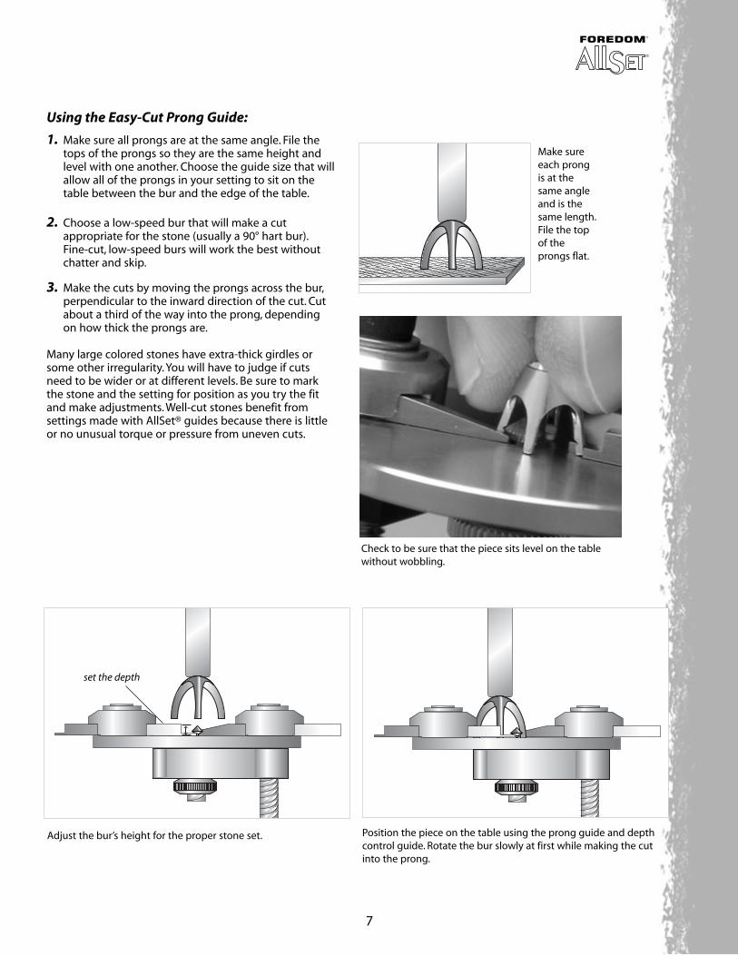
Make sureeach prongis at thesame angleand is thesame length.File the topof theprongs flat.
Adjust the bur’s height for the proper stone set. Position the piece on the table using the prong guide and depthcontrol guide. Rotate the bur slowly at first while making the cutinto the prong.
set the depth
Using the Easy-Cut Prong Guide:
1. Make sure all prongs are at the same angle. File the tops of the prongs so they are the same height and level with one another. Choose the guide size that will allow all of the prongs in your setting to sit on the table between the bur and the edge of the table.
2. Choose a low-speed bur that will make a cut appropriate for the stone (usually a 90° hart bur).Fine-cut, low-speed burs will work the best without chatter and skip.
3. Make the cuts by moving the prongs across the bur,perpendicular to the inward direction of the cut. Cut about a third of the way into the prong, depending on how thick the prongs are.
Many large colored stones have extra-thick girdles orsome other irregularity. You will have to judge if cuts need to be wider or at different levels. Be sure to mark the stone and the setting for position as you try the fitand make adjustments. Well-cut stones benefit from settings made with AllSet® guides because there is littleor no unusual torque or pressure from uneven cuts.
Check to be sure that the piece sits level on the tablewithout wobbling.
8
When adjusting the guide for prongwidth, it is very important that thebur is centered with the prong forconsistent and straight cuts.
The stop guide (depthcontrol) is not necessaryfor all settings. Use itwhenever the depth ofthe prong cut is criticalto the setting.
The end of the fence guideshould be positioned slightlyunderneath the bur. This willprevent the prong from slipping between the burand the guide.
Centeredprong
Rotationalforce
Allen boltadjustment
Prong settingwith prongtips on thetable
The Easy-Cut Prong Guide offers a wide range of adjustability.
Adjustment for smaller settings/prongs
Adjustment for larger settings/prongs
Rotational force
Adjustment for prong width
Adjustment for prong height
Rotational forceRotational force
Allen boltadjustment
Allen boltadjustment
9
cut depth cut depth
correctlycentered cut
incorrect,off-center cut
Top view of ring setting showing center-cut prongs with evenly cut heights.
Close-up views of cut prongs(Easy-Cut Prong Guide vs. freehand cutting)
The result—a perfectlyset stone!
same depth
The Easy Cut Prong Guide produces consistent settings with perfectly even height and depth cuts.
Side view of ring setting showing center-cut prongswith evenly cut heights.
correctlycentered cut
incorrect,off-center cut
10
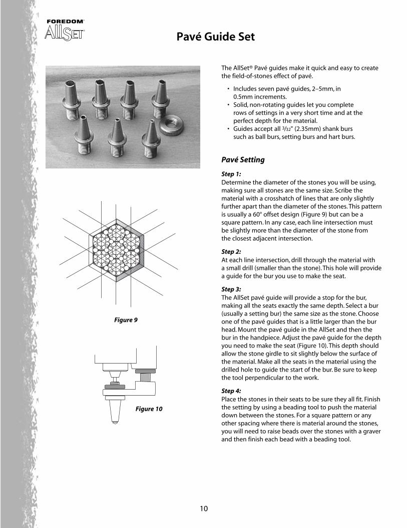
The AllSet® Pavé guides make it quick and easy to createthe field-of-stones effect of pavé.
• Includes seven pavé guides, 2–5mm, in0.5mm increments.
• Solid, non-rotating guides let you completerows of settings in a very short time and at theperfect depth for the material.
• Guides accept all 3/32" (2.35mm) shank burssuch as ball burs, setting burs and hart burs.
Pavé Setting
Step 1:Determine the diameter of the stones you will be using,making sure all stones are the same size. Scribe the material with a crosshatch of lines that are only slightlyfurther apart than the diameter of the stones. This patternis usually a 60° offset design (Figure 9) but can be asquare pattern. In any case, each line intersection must be slightly more than the diameter of the stone from the closest adjacent intersection.
Step 2:At each line intersection, drill through the material with a small drill (smaller than the stone). This hole will providea guide for the bur you use to make the seat.
Step 3:The AllSet pavé guide will provide a stop for the bur,making all the seats exactly the same depth. Select a bur(usually a setting bur) the same size as the stone. Chooseone of the pavé guides that is a little larger than the burhead. Mount the pavé guide in the AllSet and then thebur in the handpiece. Adjust the pavé guide for the depthyou need to make the seat (Figure 10). This depth shouldallow the stone girdle to sit slightly below the surface ofthe material. Make all the seats in the material using thedrilled hole to guide the start of the bur. Be sure to keepthe tool perpendicular to the work.
Step 4:Place the stones in their seats to be sure they all fit. Finishthe setting by using a beading tool to push the materialdown between the stones. For a square pattern or anyother spacing where there is material around the stones,you will need to raise beads over the stones with a graverand then finish each bead with a beading tool.
Figure 9
Figure 10
Pavé Guide Set
11
The AllSet® prong guides ensure proper depth cutting on all prongs in a single setting with one quick cut.This allows you to produce more settings with greateraccuracy. Each prong is cut to precisely the same depth so the stone will be absolutely level.
• 13 adjustable depth prong-setting guides allowyou to use bur sizes from 2.5mm to 8.5mm in 0.5mm graduated increments.
• Solid, non-rotating guides lets you hold settingsfirmly in place with no twisting or grabbing as you cut.
• Guides accept all 3/32" (2.35mm) shank burs.
Prong Setting
Step 1:Make sure all prongs on the setting are evenly spaced andangled the same. The distance between opposing prongsshould be adjusted to slightly less than the diameter ofthe stone at the height on the prongs where you intendto cut the seat.
Step 2:Choose a setting bur that is just slightly smaller than the stone’s diameter (too small a bur increases the chance that the bur will grab and skip). The best burs are non-aggressive, fine cut burs. Select the prong guideclosest to the bur size that allows the head of the bur to fit down inside the guide.
Step 3:Mount the prong guide in the AllSet L-bracket (Figure 11).Insert the bur through the guide and into the handpiecechuck. Tighten the chuck to secure the bur.
Step 4:Loosen the shaft locking screw and adjust the shaft withthe shaft adjusting nut so the shoulder of the bur is at thedesired cut-depth below the guide (Figure 12). You canalways cut deeper, so set the depth less rather than morefor the first cut. The depth of the cut should end up beinga little deeper if the stone has a thick girdle.
Step 5:Hold the setting securely and make sure you approach theprongs as straight in as possible. Holding the setting withyour fingers allows the setting to move and align itself asthe prongs come in contact with the guide.
Prongs stopflush againstguide for aperfectly levelcut.
Figure 12
Figure 11
L-bracket
Prong Guide Set
12
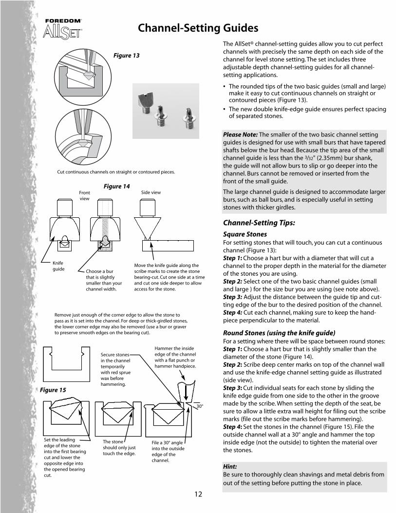
The AllSet® channel-setting guides allow you to cut perfectchannels with precisely the same depth on each side of thechannel for level stone setting. The set includes threeadjustable depth channel-setting guides for all channel-setting applications.
• The rounded tips of the two basic guides (small and large)make it easy to cut continuous channels on straight or contoured pieces (Figure 13).
• The new double knife-edge guide ensures perfect spacing of separated stones.
Please Note: The smaller of the two basic channel settingguides is designed for use with small burs that have taperedshafts below the bur head. Because the tip area of the small channel guide is less than the 3/32" (2.35mm) bur shank,the guide will not allow burs to slip or go deeper into thechannel. Burs cannot be removed or inserted from the front of the small guide.
The large channel guide is designed to accommodate largerburs, such as ball burs, and is especially useful in settingstones with thicker girdles.
Channel-Setting Tips:
Square StonesFor setting stones that will touch, you can cut a continuouschannel (Figure 13):Step 1: Choose a hart bur with a diameter that will cut achannel to the proper depth in the material for the diameterof the stones you are using.Step 2: Select one of the two basic channel guides (smalland large ) for the size bur you are using (see note above).Step 3: Adjust the distance between the guide tip and cut-ting edge of the bur to the desired position of the channel.Step 4: Cut each channel, making sure to keep the hand-piece perpendicular to the material.
Round Stones (using the knife guide)For a setting where there will be space between round stones:Step 1: Choose a hart bur that is slightly smaller than thediameter of the stone (Figure 14).Step 2: Scribe deep center marks on top of the channel walland use the knife-edge channel setting guide as illustrated(side view).Step 3: Cut individual seats for each stone by sliding theknife edge guide from one side to the other in the groovemade by the scribe. When setting the depth of the seat, besure to allow a little extra wall height for filing out the scribemarks (file out the scribe marks before hammering).Step 4: Set the stones in the channel (Figure 15). File theoutside channel wall at a 30° angle and hammer the topinside edge (not the outside) to tighten the material overthe stones.
Hint:Be sure to thoroughly clean shavings and metal debris fromout of the setting before putting the stone in place.
Knifeguide Choose a bur
that is slightlysmaller than yourchannel width.
Move the knife guide along thescribe marks to create the stonebearing-cut. Cut one side at a timeand cut one side deeper to allowaccess for the stone.
Remove just enough of the corner edge to allow the stone topass as it is set into the channel. For deep or thick-girdled stones,the lower corner edge may also be removed (use a bur or graverto preserve smooth edges on the bearing cut).
Frontview
Cut continuous channels on straight or contoured pieces.
Set the leading edge of the stoneinto the first bearingcut and lower theopposite edge intothe opened bearingcut.
The stoneshould only justtouch the edge.
File a 30° angleinto the outsideedge of thechannel.
Hammer the insideedge of the channelwith a flat punch orhammer handpiece.
Secure stonesin the channeltemporarilywith red spruewax beforehammering.
30°
Side view
Channel-Setting Guides
Figure 14
Figure 15
Figure 13
13
Model-Maker’s Milling Assembly
Master Kit
Pavé-Setting Kit
Channel-Setting Kit
Prong-Setting Kit
Model-Maker’s #117-929Milling Assembly This new multi-purpose milling accessorymakes working in metal and wax markedlymore efficient and convenient.
Master Kit #117-909Quickly and easily achieve perfect resultsin all your stone-setting operations.Includes a Foredom® No. 30® handpiece,AllSet® handpiece attachments, completeset of guides and video.
Prong-Setting Kit #117-916Produce consistent settings nearly 10times faster than by hand! Includes AllSet®handpiece attachment, 13 prong-settingguides, guide locking nut, Allen wrenchand instructions—all in a fitted box.
Prong Guides Only #117-917
Pavé-Setting Kit #117-922Allset™ handpiece attachment, seven pavéguides (for setting a number of stones in apattern to produce a field-of-stones effect),guide locking nut, Allen wrench andinstructions—all in a fitted box.
Pavé Set Guides Only #117-923
Channel-Setting Kit #117-958Cut perfect channels and maximize yourproduction. Includes AllSet® handpieceattachment, three channel-setting guides,(small, large for baguette and knife-edge),guide locking nut, Allen wrench andinstructions—in a fitted box.
Channel Set Guides Only #117-957
Kit for Foredom® #10 handpiece
Quick-Change Adapter Kit #117-950for Foredom® #10 HandpieceIncludes Allset® threaded handpieceadapter, Easy-Cut prong guide and threechannel setting guides: small, large (forbaguette settings) and a knife-edge guide.Handpiece (#117-043) sold separately.
Kit for Foredom® #52 handpiece
Quick-Change Adapter Kit #117-951for Foredom® #52 HandpieceIncludes Allset® threaded handpieceadapter, Easy-Cut prong guide and threechannel setting guides: small, large (forbaguette settings) and a knife-edge guide.Handpiece (#117-593) sold separately.
Fence Assembly Kit #117-955Converts the milling assembly (top right)
into a fully operational table saw and
planer. Use with cutters and burs to cut,
grind or plane gold, platinum, silver, wax
and more. Positions within a 180° range
and can be set in two different directions
for maximum flexibility.
Sander/Planer Kit #117-956Grind, sand and polish with ease using this
compact sander. Adjusts easily from 0° to
90° angle and has three-position guide for
compound angles. Works with the
Foredom® #30® handpiece. Includes planer
attachment and a complete set of 3M
sanding/lapping films and Trizact A5 disc.
Allset® Adapter #117-954Get easy, hands-free operations for many
configurations when used with the milling
assembly (top right) or sander/planer
(above). Adjusts to various angles, heights
and positions. Slides into a GRS mounting
plate (sold separately).
Sander/Planer Kit
Customize Your Own Setting Operation with Allset® Kits!
Customize your AllSet® just the way you want it! Choose exactly what you need to maximize your efficiency
and guarantee great results. If you already have a Foredom® handpiece or some of the equipment included in
the kits, just add the AllSet components you want from the selection described below (see complete descrip-
tions and pricing in your current Rio Grande Tools & Equipment catalog. Each AllSet component is made in USA).
Allset® Adapter
The Allset® Accessory Video #560-057Allset® co-inventor and award-winning jeweler and tooldesigner, Jeffrey Mathews, shows you how to use this revolutionary system to speed stone-setting and increaseaccuracy. VHS, 31 minutes.
7500 Bluewater Road NW
Albuquerque, NM 87121-1962 USA
phone 800.545.6566 • fax 800.965.2329 • local 505.839.3300
international 505.839.3011 • international fax 505.839.3016