Page | 1 FACULTY OF CIVIL ENGINEERING UNIVERSITY OF BELGRADE Department for Road, Railroad and Airport Engineering Bul. kralja Aleksandra 73, 11000 Belgrade, Serbia EXECUTIVE REPORT ON MASTER THESIS: MASTER PLAN OF THE AIRPORT DIVCI – VALJEVO Author: Mr. Bojan Besednik, MSc C.E. Mentor: Mr. Dejan Gavran, PhD C.E. Summary: The paper presents the Master plan of municipal airport “Divci”, located at the eastern outskirt of Valjevo, town in central Serbia. The master plan in concern was developed while working on master thesis at the Faculty of Civil Engineering, University of Belgrade, Departemnt for Road, Railroad and Airport Engineering. Meteorological, navigational and environmental data were analysed first. Micro location of the airport was very tight. State highway M - 4, as well as primary railway Belgrade - Bar, follows the northern perimeter of the airport, while local road R - 202 cuts deeply through the eastern approach zone. These limitations were turned into advantages by setting the most of the road access on the spacious slab above the railway lines, thus integrating both air and railway passenger flows. For such adopted Master plan, detailed preliminary design (including grading plans) was developed for the entire airside. Key words: Master plan, airport, manoeuvering areas, airport location analysis Chapter 1. Introduction The Master plan of municipal airport “Divci” presented in this paper starts with analysis of traffic, topographic, urban, meteorological, navigational and environmental conditions and determines the micro location of the new runway. One of the thesis goals was to retain existing turf runway. Newly added runway supports IFR operations for code number 2 aircraft and VFR operations for code number 3 aircraft. Municipal airport “Divci” is designed to handle commercial flights of aircraft with wingspan of up to 29 m, maximum take-off weight – MTOW of 42.000 kg, while carrying 100 passengers, as well as helicopters with rotor diameter of up to 12 m. Additionally, the airport “Divci” is to retain instructional flying and sport activities (such as powered flying, pleasure flying, gliding, parachuting, hang gliding, paragliding). Also, there are plenty of other civil and general aviation activities that are planned at the airport: charter flights, air taxi, commercial and non-commercial business aviation, agriculture, construction, photography, surveying, search and rescue, aerial advertisement, etc.
Transcript
Page | 1
FACULTY OF CIVIL ENGINEERING
UNIVERSITY OF BELGRADE Department for Road, Railroad and Airport Engineering Bul. kralja Aleksandra 73, 11000 Belgrade, Serbia
EXECUTIVE REPORT ON MASTER THESIS:
MASTER PLAN OF THE AIRPORT DIVCI – VALJEVO Author: Mr. Bojan Besednik, MSc C.E. Mentor: Mr. Dejan Gavran, PhD C.E. Summary:
The paper presents the Master plan of municipal airport “Divci”, located at the eastern outskirt of Valjevo, town in central Serbia. The master plan in concern was developed while working on master thesis at the Faculty of Civil Engineering, University of Belgrade, Departemnt for Road, Railroad and Airport Engineering. Meteorological, navigational and environmental data were analysed first. Micro location of the airport was very tight. State highway M - 4, as well as primary railway Belgrade - Bar, follows the northern perimeter of the airport, while local road R - 202 cuts deeply through the eastern approach zone. These limitations were turned into advantages by setting the most of the road access on the spacious slab above the railway lines, thus integrating both air and railway passenger flows. For such adopted Master plan, detailed preliminary design (including grading plans) was developed for the entire airside. Key words: Master plan, airport, manoeuvering areas, airport location analysis Chapter 1. Introduction
The Master plan of municipal airport “Divci” presented in this paper starts with analysis of traffic,
topographic, urban, meteorological, navigational and environmental conditions and determines the
micro location of the new runway. One of the thesis goals was to retain existing turf runway. Newly
added runway supports IFR operations for code number 2 aircraft and VFR operations for code
number 3 aircraft.
Municipal airport “Divci” is designed to handle commercial flights of aircraft with wingspan of up to 29
m, maximum take-off weight – MTOW of 42.000 kg, while carrying 100 passengers, as well as
helicopters with rotor diameter of up to 12 m. Additionally, the airport “Divci” is to retain instructional
flying and sport activities (such as powered flying, pleasure flying, gliding, parachuting, hang gliding,
paragliding). Also, there are plenty of other civil and general aviation activities that are planned at the
airport: charter flights, air taxi, commercial and non-commercial business aviation, agriculture,
construction, photography, surveying, search and rescue, aerial advertisement, etc.
Page | 2
Figure 1. Location of the airport “Divci” in relation to town of Valjevo
Chapter 2. Existing Facilities
This chapter gives an insight into the airport’s position in relation to the town of Valjevo and nearby
settlements, surrounding transport infrastructure, utilities and geographical features. Location and
orientation of existing turf runway, as well as existing airport’s facilities and access routes are
presented on Fig. 1.
Chapter 3. Airport Site Analysis
This chapter provides detailed analysis of airport location: meteorological, navigational,
environmental, geotechnical and traffic analysis, compatibility with existing urban plans, etc.
Geotechnical analyses cover the terrain morphology, geological, hydrological, seismic and ground
water analysis.
Meteorological analyses cover the wind, cloud base, horizontal visibility and precipitation analysis.
Runway usability values for three alternative runway orientations are shown on Fig. 2.
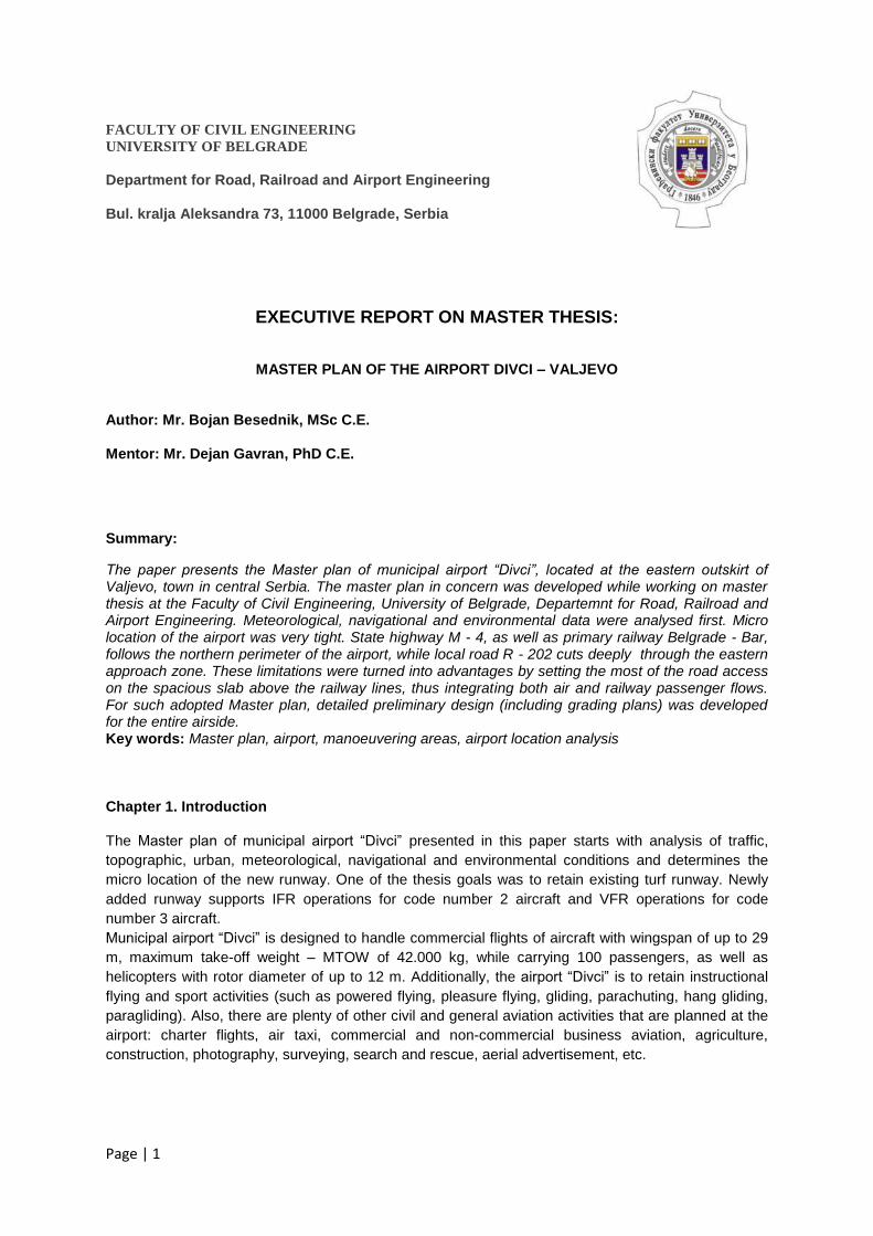
Control of obstacles was carried out by comparing the 3D model of obstacle limitation surfaces
against the digital terrain model. Manmade obstacles were taken into account also. See Aerodrome
Obstacle Charts – type A and B on Fig 3. and Fig. 4.
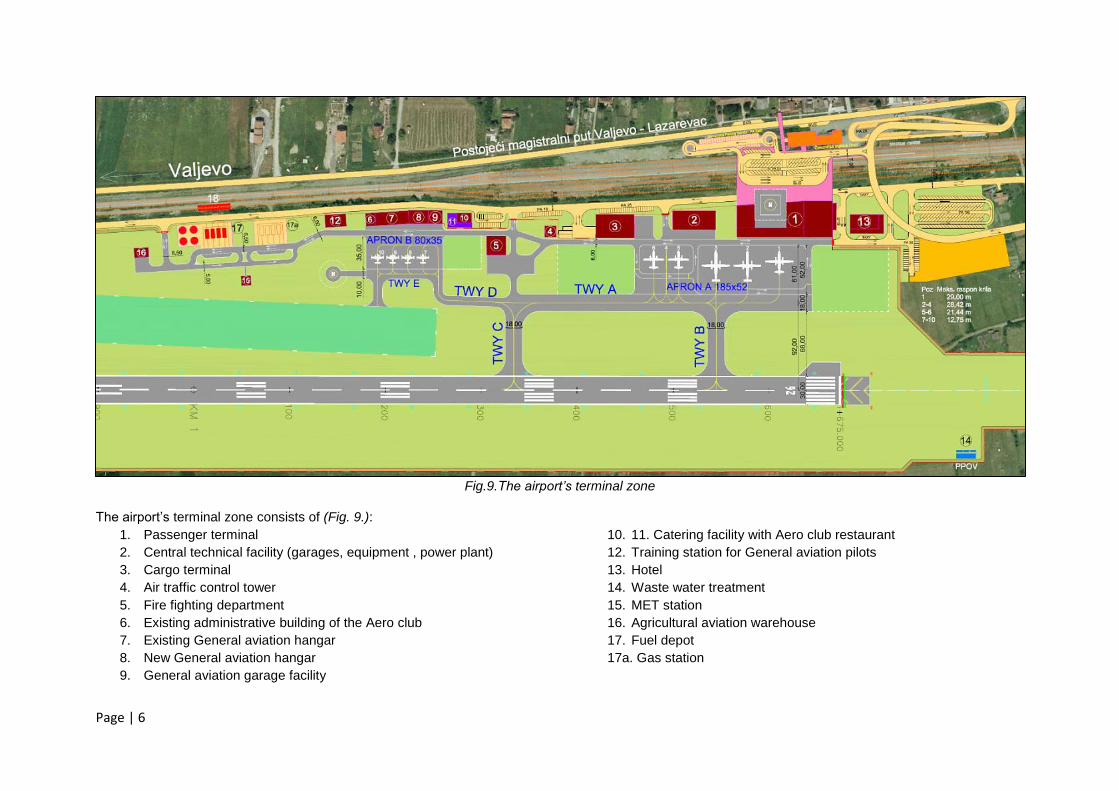
Besides the air and water pollution, the aircraft noise presents by far the most prominent
environmental issue. Anticipated noise levels in the vicinity of the airport are shown on Fig. 5. Noise
level contours have been generated by using INM 7.0 intended noise model.
Figure 2. Wind roses for three alternative orientations of new RWY
Page | 3
Figure 3. Aerodrome obstacle chart – type A
Figure 4. Aerodrome obstacle chart – type B
Figure 5. Noise level contours
Page | 4
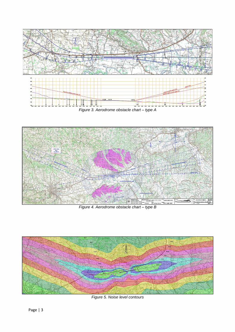
Figure 6. Master plan of airport “Divci” – Valjevo – the final stage
Figure 7. Master plan of airport “Divci” – Valjevo – Stages of development
Page | 5
Chapter 4. Airport Master Plan
Existing airport site is very tight. State highway M - 4, as well as primary railway Belgrade - Bar,
follows the northern perimeter of the airport, while local road R - 202 cuts deeply through the eastern
approach zone. These limitations were turned into advantages by setting the most of the road access
on the spacious slab above the railway lines, thus integrating both air and railway passenger flows.
The very shape of the airport property dictates the grouping of the airport facilities in the north -
eastern corner of the airport complex (see Fig. 6.).
Several alternatives of the Master plan were considered. For the adopted alternative two stages of
development were proposed (see Fig. 7.). As early as in the first stage, the airport is supposed to be
an international one, with all facilities for necessary aircraft handling and passenger processing
present. In the first phase the ground access is elevated onto the structure spanning the railway lines.
In the second stage of the development the apron, passenger terminal building and the ground
access (slab above the railway lines) are further expanded.
The runway code is 3C. Runway dimensions are 1675 x 30 m, while the width of the runway strip is
150 m. Existing turf runway was shortened down 687 m in order to keep the gliders away from the
paved surfaces.
There are two aprons: apron A is to serve commercial air traffic, while apron B is intended for General
Aviation. Apron A is located at the north - eastern corner of the airport, where the airport property
reaches its maximum width, while apron B occupies central part of the airport complex. There are also
five taxiways connecting the aprons with the runway and providing the necessary link among the
aprons and the facilities within the airside.
There are two possible heliport locations. The first one sits atop the second floor of the passenger
terminal building, while the alternative one is situated aside the General Aviation apron.
Though the extremely tight, the space between terminal buildings and railway lines provides for the
efficient ground access, even allowing separation of passenger cars and heavy duty vehicles (tankers
and cargo trucks). Accordingly, there will be two different railway crossings, one for the passenger
traffic (private cars and buses) and another one for trucks (see Fig. 8.). Passenger railway crossing is
grade separated and integrated with the structure spanning the railway lines, while the at - grade
separated crossing (primarily for trucks) is moved further to the west.
Figure 8. Passenger terminal area with grade - separated railway crossing
Page | 6
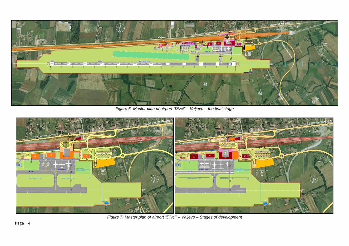
Fig.9.The airport’s terminal zone
The airport’s terminal zone consists of (Fig. 9.):
1. Passenger terminal
2. Central technical facility (garages, equipment , power plant)
3. Cargo terminal
4. Air traffic control tower
5. Fire fighting department
6. Existing administrative building of the Aero club
7. Existing General aviation hangar
8. New General aviation hangar
9. General aviation garage facility
10. 11. Catering facility with Aero club restaurant
12. Training station for General aviation pilots
13. Hotel
14. Waste water treatment
15. MET station
16. Agricultural aviation warehouse
17. Fuel depot
17a. Gas station
Page | 7
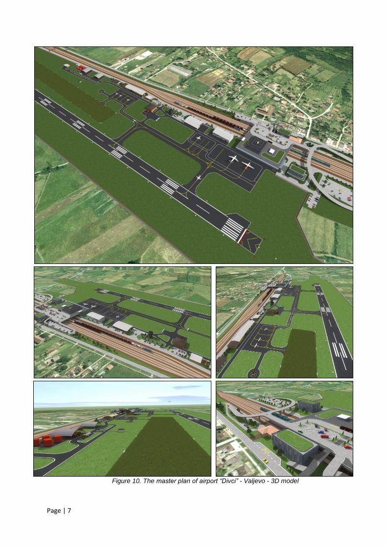
Figure 10. The master plan of airport “Divci” - Valjevo - 3D model
Page | 8
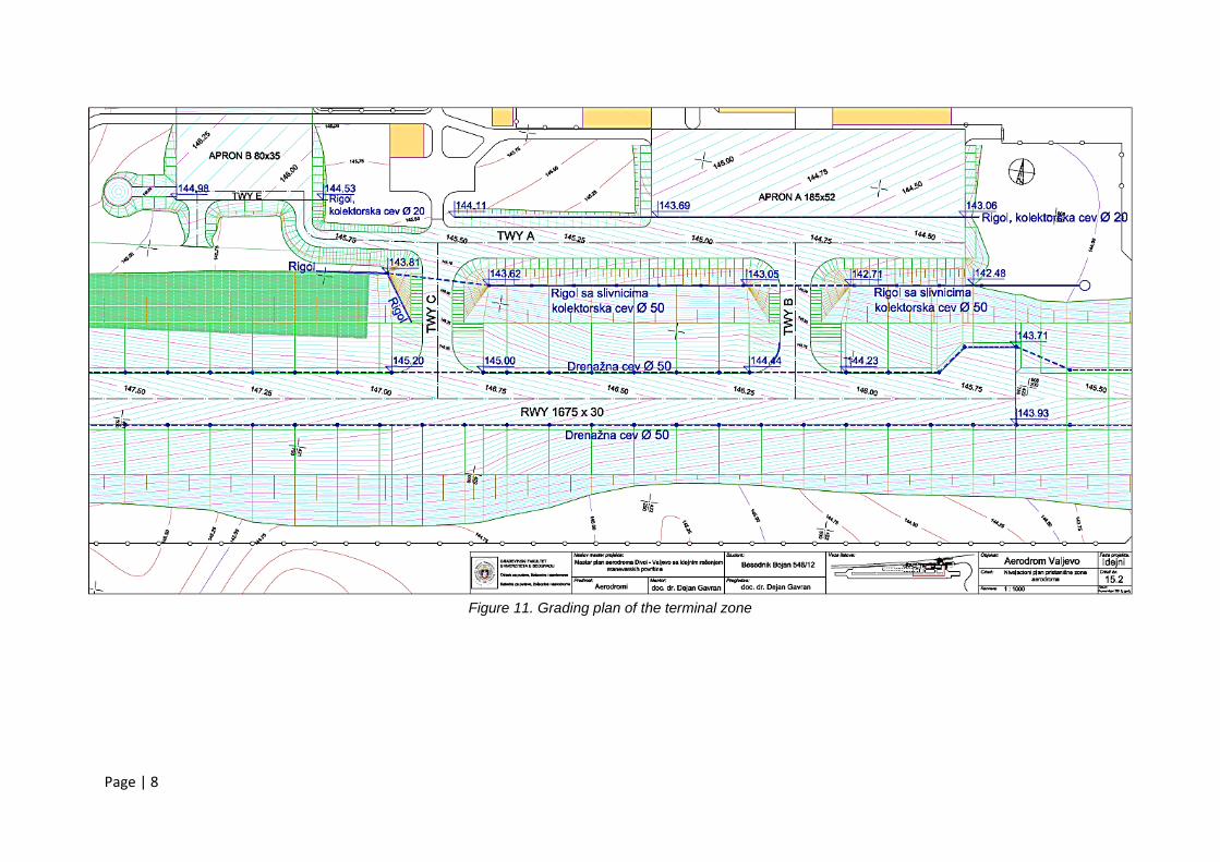
Figure 11. Grading plan of the terminal zone
Page | 9
Figure 11. Airport layout with runway longitudinal profile
Chapter 5. Preliminary Airside Design
Design solution of the airside was documented by using detailed grading plans with the contour
interval of 5 cm. Graded zone covers paved surfaces, shoulders, runway and taxiway strips, service
roads, etc. (Fig. 10.). All longitudinal and cross sections and the entire airside concept as well, are
decided in relation to drainage requirements (Fig.11. and 12.). All surface and subsurface elements of
drainage were checked against the elements of the airside and all inlets and manholes, as well as
pipes and culverts were defined in 3D.
Based on the MTOW of the critical aircraft and the predicted number of annual operations
(approximately 25.000 operations), the pavement structures were determined also. Thickness of each
particular pavement layer has been chosen by LDFFA software, recommended by FAA.
Figure 12. Runway cross section with drainage detail
Chapter 6. Overall Bill of Quantities - Master Plan Level
The bill of quantities includes all elements of the airside, terminal buildings and ground access. The
total cost of the final stage of development is 42,74 million euros.
Chapter 7. Overall Bill of Quantities for the Airside - Preliminary Design Level
The total cost of the airside construction is 3,23 million euros. This figure includes all paved areas,
graded surfaces and the construction of the drainage system.