Page 1
Faculty of Civil Engineering Institute of Construction Informatics
MASTER THESIS
Investigation of data sharing in the Structural Engineering
domain
By
Rafeequl Islam
Matriculation Number: 4748050
A Thesis work submitted to the Institute of Construction Informatics,
Faculty of Civil Engineering, Technische Universität Dresden
In partial fulfilment of the requirements for the
Degree of Master of Science
In
Advanced Computational and Civil Engineering Structural Studies
Supervisor
Prof. Dr.-Ing. Karsten Menzel
Tutor
MSc. Janakiram Karlapudi
Dresden, January 2020
Page 5
iv
Declaration of originality
I confirm that this assignment is my own work and that I have not sought or used inadmissible
help of third parties to produce this work. I have fully referenced and used inverted commas
for all text directly quoted from a source. Any indirect quotations have been marked as such.
This work has not yet been submitted to another examination institution – neither in Germany
nor outside Germany – neither in the same nor in the similar way and has not yet been
published.
Dresden, 20-Jan-2020
Place, Date
__________________
Signature
Page 6
v
Acknowledgements
I express sincere gratitude to Prof. Dr.-Ing. habil. Karsten Menzel and Prof. Dr. Ing. Raimar
Schrer for giving me the opportunity to do my Master Thesis in the Institute of Construction
Informatics, Faculty of Civil Engineering and for providing immense support throughout the
process.
My sincere gratitude to MSc. Janakiram Karlapudi for his guidance and assistance throughout
each step of the practical and scientific tasks. His patience, good will and kindness have enabled
the completion of this thesis.
I am indeed very grateful to my parents for their love and support. I am very thankful to my
friends for their support and encouragement all through this tough period.
Page 7
vi
Table of Contents
Declaration of originality ....................................................................................................... iv
Acknowledgements .................................................................................................................. v
Table of Contents .................................................................................................................... vi
List of Figures ....................................................................................................................... viii
List of Tables ........................................................................................................................... ix
List of Abbreviations and Symbols ........................................................................................ x
1. Introduction ..................................................................................................................... 2
1.1 Building Information Modeling ................................................................................. 2
1.2 Description of Research Statement ............................................................................. 4
1.3 Research Objective and Approach .............................................................................. 4
1.4 Thesis Layout ............................................................................................................. 4
2. Literature Studies ............................................................................................................ 6
2.1 Interoperability Issues ................................................................................................. 6
2.2 Level of Details (LOD) ............................................................................................... 7
2.3 Data transfer requirement .......................................................................................... 10
3. Data sharing model ........................................................................................................ 14
3.1 IFC Schema .............................................................................................................. 14
3.2 Model View Definition (MVD) ................................................................................. 16
3.3 Structural data in IFC ................................................................................................ 17
3.3.1 Structural elements....................................................................................... 18
3.3.2 Geometry and placement ............................................................................. 19
3.3.3 Loads definitions .......................................................................................... 20
3.3.4 Material definitions ...................................................................................... 20
3.3.5 Structural Results ......................................................................................... 20
4. Demonstration of data sharing ..................................................................................... 22
4.1 Research Methodology ............................................................................................ 22
4.2 Revit Model ............................................................................................................... 23
4.2 IFC export ................................................................................................................ 25
4.3 Verification (FZKViewer) ......................................................................................... 27
4.4 Import to SCIA Engineer ........................................................................................... 30
5. Results and Discussions ................................................................................................. 33
6. Conclusions and Outlook .............................................................................................. 35
Page 8
vii
References ............................................................................................................................... 36
Page 9
viii
List of Figures
Figure 1.1: Graphical representation of BIM concept and its possible by products [3]. ........... 2
Figure 1.2: Dimensions of BIM ................................................................................................. 3
Figure 2.1: Interoperability between various software tools 6
Figure 3.1: buildingSMART standards triangle 14
Figure 3.2: IFC data schema conceptual layer ......................................................................... 15
Figure 4. 1: Sequence of operations for demonstration of data sharing 23
Figure 4. 2: Three Storey composite structure - Revit model .................................................. 24
Figure 4. 3: Export parametres in Revit for IFC ...................................................................... 25
Figure 4. 4: IFC export Layers mentioned in Revit 2019 ........................................................ 27
Figure 4. 5: Summary of entities and Relations ....................................................................... 28
Figure 4. 6: IFC model in FZK viewer .................................................................................... 28
Figure 4. 7: Connection of beam to circular column error ...................................................... 29
Figure 4. 8: Circular column is replaced with rectangular column - Revit Model .................. 29
Figure 4. 9: Circular column is replaced with rectangular column - FZK Viewer .................. 30
Figure 4. 10: Import statistics of SCIA engineer (With circular columns) .............................. 31
Figure 4. 11: Import statistics of SCIA engineer (With rectangular columns) ........................ 31
Figure 4. 12: Imported model into SCIA (Analytical Model) ................................................. 32
Figure 5. 1: Nodes dislocation due to non-overlapping members (Above) and nodes are joint
at one point due to overlap of members (Below) 34
Page 10
ix
List of Tables
Table 2.1 Comparison of American Institute of Architect’s Definitions of Level of Detail with
BIMForum’s Level of Development Interpretation [13] [14]. .................................................. 9
Table 2.2: Information required for various structural elements at different LOD ................. 13
Table 4. 1: Construction details of structural elements 25
Table 4. 2: IFC export specifications ....................................................................................... 26
Page 11
x
List of Abbreviations and Symbols
BIM Building Information Modeling
AEC Architecture, Engineering and Construction
AEC/FM Architecture, Engineering and Construction/Facility
management
IFC Industry Foundation Classes
IAI International Alliance for Interoperability
LOD Level of Detail
Page 12
2
1. Introduction
1.1 Building Information Modeling
Building Information Modeling (BIM) is one of the most promising developments in the
architecture, engineering and construction (AEC) industries. BIM is a process supported by
various tools and technologies involving the generation and management of digital
representations of physical and functional characteristics of civil engineering structures. These
digital models contain precise geometry and data needed for the design, construction and
maintenance. BIM accommodates all the information and functions needed to model and
support the life cycle of structures (refer to figure 1.1) resulting in better quality at lower cost
and reduced project duration. The term 'Building Information Model' first appeared in a 1992
paper by G.A. van Nederveen and F. P. Tolman [1]. The US National Building Information
Model Standard Project Committee defines BIM as: [2]
“Building Information Modeling (BIM) is a digital representation of physical and functional
characteristics of a facility. A BIM is a shared knowledge resource for information about a
facility forming a reliable basis for decisions during its life-cycle; defined as existing from
earliest conception to demolition”
Figure 1.1: Graphical representation of BIM concept and its possible by products [3].
Traditional building design and construction was largely dependent on 2D technical drawings
(Plans, Elevations and Sections) but BIM extends this beyond 3D, augmenting the three
Page 13
3
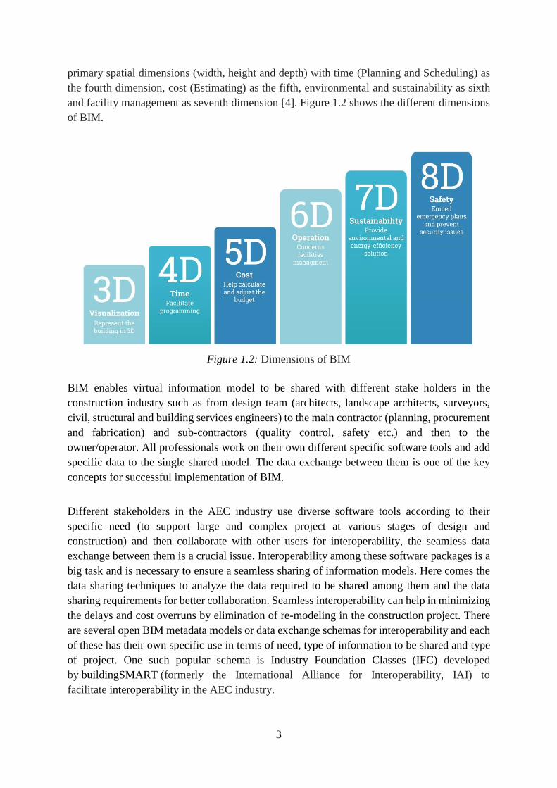
primary spatial dimensions (width, height and depth) with time (Planning and Scheduling) as
the fourth dimension, cost (Estimating) as the fifth, environmental and sustainability as sixth
and facility management as seventh dimension [4]. Figure 1.2 shows the different dimensions
of BIM.
Figure 1.2: Dimensions of BIM
BIM enables virtual information model to be shared with different stake holders in the
construction industry such as from design team (architects, landscape architects, surveyors,
civil, structural and building services engineers) to the main contractor (planning, procurement
and fabrication) and sub-contractors (quality control, safety etc.) and then to the
owner/operator. All professionals work on their own different specific software tools and add
specific data to the single shared model. The data exchange between them is one of the key
concepts for successful implementation of BIM.
Different stakeholders in the AEC industry use diverse software tools according to their
specific need (to support large and complex project at various stages of design and
construction) and then collaborate with other users for interoperability, the seamless data
exchange between them is a crucial issue. Interoperability among these software packages is a
big task and is necessary to ensure a seamless sharing of information models. Here comes the
data sharing techniques to analyze the data required to be shared among them and the data
sharing requirements for better collaboration. Seamless interoperability can help in minimizing
the delays and cost overruns by elimination of re-modeling in the construction project. There
are several open BIM metadata models or data exchange schemas for interoperability and each
of these has their own specific use in terms of need, type of information to be shared and type
of project. One such popular schema is Industry Foundation Classes (IFC) developed
by buildingSMART (formerly the International Alliance for Interoperability, IAI) to
facilitate interoperability in the AEC industry.
Page 14
4
1.2 Description of Research Statement
There are several stakeholder in the domain of structural engineering with different technical
roles such as architects, structural engineers, CAD designers, quantity surveyors, planners,
tenderers, mechanical engineers, electrical engineers, HVAC team etc. Some are responsible
for individual component (Architectural, structural, Mechanical, etc.) modeling while others
role may vary from integrating all structural components modelled into virtual model to
perform overall structural, energy, HVAC, etc. analysis. The efficiency of data sharing and
data transfer between them will enhance the overall design process (from concept design to
detailed design).
This thesis is about the analysis of the data sharing by different stakeholders in the domain of
structural engineering. The focus is on IFC meta-data model schema as a vendor neutral data
format to hold exchange and manage the information. The focus is on capability of different
software tools used in the structural engineering domain to perform data exchange using IFC
format.
1.3 Research Objective and Approach
The objectives of this research work are:
1. Identification of the data transfer requirements between different stakeholders in
structural engineering domain at various stages of design as described in different Level
of Detail (LOD) specifications by American Institute of Architects (AIA).
2. To investigate the current IFC meta-data model for efficient interoperability with
respect to the above identified data transfer requirements.
3. Identification of different software tools used in the domain of structural engineering
that support IFC data sharing.
4. Demonstration of data sharing between these tools and analysis of results for feasibility
data sharing requirements.
For analysing the semantic interoperability, a suitable building model (Composite structure) is
modelled in Revit (Architectural, structural and MEP modelling software) at LOD 300. This
model is then exported as IFC file from Revit software. The exported IFC file is then analysed
using FZK viewer (IFC model viewer) for data quality, modelling errors and geometrical
representation of building components. Now, this IFC file is imported to SCIA Engineer
(Structural Analysis and design software). After importing the IFC file, SCIA converts IFC
models to internal models and the structural analysis is performed.
1.4 Thesis Layout
Page 15
5
Part 1 gives the overview of BIM and its dimensions. It then focus on the need for data sharing
in structural engineering domain and interoperability issues between them. Furthermore, this
part describes the research statement and its objective and approach used.
Part 2 gives a broad literature study review and discusses the interoperability issues between
various software tools used in the structural engineering domain. It summarizes the previous
works done by various researchers in this field. It discusses the different Level of Detail (LOD)
as defined by American Institute of Architects. (AIA). It also discusses the data transfer
requirement at different LODs required by different stakeholders in design stage.
Part 3 discusses the IFC data sharing model, its concept and architecture. Then it analyses how
the structural data is represented in IFC file format. Structural elements. Part 4 provide a
demonstration of data sharing with a suitable building model. Revit and SCIA engineer is used
as software tools.
Lastly, the results obtained from part 4 are then analyzed and investigated for the feasibility of
data transfer for semantic interoperability. The interoperability issues are addressed. And the
work is concluded with further studies.
Page 16
6
2. Literature Studies
Building design process typically involves two separate phases, architectural design and
structural design with distinct objectives. Architectural design is focused on defining the space
arrangement and geometric information of various architectural elements (Input for structural
design), while structural design focus on analyzing the mechanical properties of building
elements and structure. Structural design involves several consultants and engineers
performing structural analysis and design utilizing different software tools. Software
interoperability is necessary to ensure a seamless sharing of information models. Due to
multiple disciplines, data sharing and exchange between diverse software tools become an
inevitable need, and a public and rich data format is necessary for data interoperability.
Consequently, IFC schema was developed by buildingSMART to support data sharing and
exchange. IFC is an open data schema and most widely used schema for data sharing among
all the disciplines of AEC industry and across the entire life cycle of building. Currently 68
software application have finished buildingSMART certification process and IFC4.2 is the
latest version.
2.1 Interoperability Issues
Interoperability is the ability to transfer data between applications, and for multiple
applications to jointly contribute to the work at hand. It is a seamless data exchange at the
software level. National Institute of Standards and Technology study estimated that inadequate
interoperability for the capital facilities industry led to $15.8 billion in annual unnecessary costs
in USA in 2002 [5]. Interoperability is achieved by mapping parts of each participating
software’s internal data structure to a universal data model and vice versa. If the employed
universal data model is open (such as IFC), any application can participate in the mapping
process and thus become interoperable with any other application that also participated in the
mapping. Interoperability eliminates the costly practice of integrating every application (and
version) with every other application (and version) and regeneration of models with specific
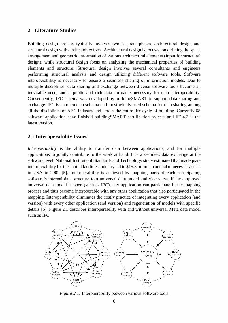
details [6]. Figure 2.1 describes interoperability with and without universal Meta data model
such as IFC.
Figure 2.1: Interoperability between various software tools
Page 17
7
Lai and Deng studied interoperability issues during bidirectional data exchanges using IFC.
They conducted a data interoperability experiment, including architectural, structural and MEP
models from a practical project, to analyze issues in the process of data import and re-export
between heterogeneous software. The results are summed as: (a) software tools cannot well
interpret several objects belonging to other disciplines due to the difference in domain
knowledge; (b) software tools have diverse methods to represent the same geometry, properties
and relations, leading to inconsistent model data. They also suggested a method for improving
the existing bidirectional data sharing and exchange: BIM software tools export models using
IFC format, and these IFC models are imported into a common IFC-based BIM platform for
data interoperability [7].
Y.-S. Jeong et al. conducted test for data exchanges of precast concrete. They tested a small
but complex building model and have shown that despite progress in developing and
implementing IFC, much work is still needed to achieve fully effective interoperability.
Imperfect exchanges arose from the lack of uniformity in the way the internal object schemas
were mapped to IFC objects and properties. Their tests showed clearly the need for a mutually
agreed upon standard that defines how precast architectural facades should be modeled and
mapped to the IFC schema [8].
A BIM model is to be shared between different software applications which are used by the
different stakeholders in the BIM process. Thus it is crucial for the data information model to
have seamless sharing among the various software’s. To achieve successful data sharing or
data interoperability it is necessary that each part of the participating data structure must map
itself with the universal data structure such as IFC, without any exceptions. Various researches
has been carried out to test the data exchange using IFC and concluded much work is still
needed to achieve fully effective interoperability.
2.2 Level of Details (LOD)
BIM presents information in the form of 3D graphical representation which is further
associated with more characteristic features of elements. The Level of Detail (LOD)
specification is a reference tool intended to improve the quality of communication among the
users of BIM about the details of elements in model. The LODs provide five snapshots of the
progression of an element from conceptual to actual design [12].
The term LOD was first introduced in 2004 by Vico Company. In 2008, it was further
developed by the American Institute of Architects (AIA) releasing their first BIM contract
document - AIA E202 Building Information Modeling Protocol Exhibit, by describing it as
‘level of completeness to which a model element is developed’. They outlined five levels of
detail (LOD 100-500) for defining the amount of detail in a particular BIM model. In 2013 a
group called BIMForum published Level of Development Specification, they explained all the
terms by providing definitions and illustrations of BIM elements of different building systems
at different stages of their development and use in the design and construction process.
Page 18
8
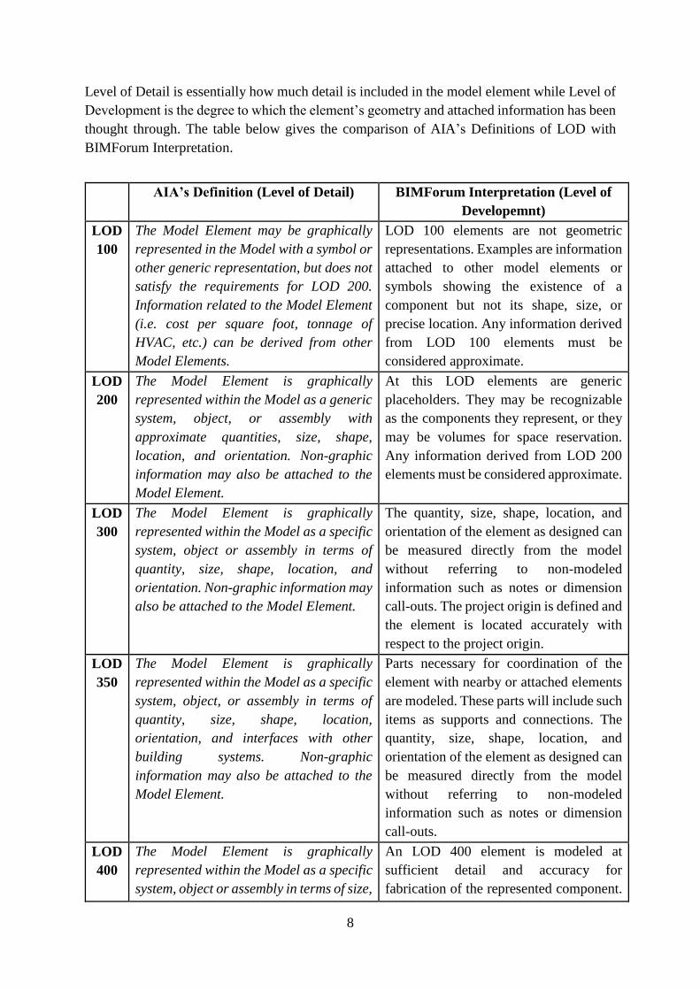
Level of Detail is essentially how much detail is included in the model element while Level of
Development is the degree to which the element’s geometry and attached information has been
thought through. The table below gives the comparison of AIA’s Definitions of LOD with
BIMForum Interpretation.
AIA’s Definition (Level of Detail) BIMForum Interpretation (Level of
Developemnt)
LOD
100
The Model Element may be graphically
represented in the Model with a symbol or
other generic representation, but does not
satisfy the requirements for LOD 200.
Information related to the Model Element
(i.e. cost per square foot, tonnage of
HVAC, etc.) can be derived from other
Model Elements.
LOD 100 elements are not geometric
representations. Examples are information
attached to other model elements or
symbols showing the existence of a
component but not its shape, size, or
precise location. Any information derived
from LOD 100 elements must be
considered approximate.
LOD
200
The Model Element is graphically
represented within the Model as a generic
system, object, or assembly with
approximate quantities, size, shape,
location, and orientation. Non-graphic
information may also be attached to the
Model Element.
At this LOD elements are generic
placeholders. They may be recognizable
as the components they represent, or they
may be volumes for space reservation.
Any information derived from LOD 200
elements must be considered approximate.
LOD
300
The Model Element is graphically
represented within the Model as a specific
system, object or assembly in terms of
quantity, size, shape, location, and
orientation. Non-graphic information may
also be attached to the Model Element.
The quantity, size, shape, location, and
orientation of the element as designed can
be measured directly from the model
without referring to non-modeled
information such as notes or dimension
call-outs. The project origin is defined and
the element is located accurately with
respect to the project origin.
LOD
350
The Model Element is graphically
represented within the Model as a specific
system, object, or assembly in terms of
quantity, size, shape, location,
orientation, and interfaces with other
building systems. Non-graphic
information may also be attached to the
Model Element.
Parts necessary for coordination of the
element with nearby or attached elements
are modeled. These parts will include such
items as supports and connections. The
quantity, size, shape, location, and
orientation of the element as designed can
be measured directly from the model
without referring to non-modeled
information such as notes or dimension
call-outs.
LOD
400
The Model Element is graphically
represented within the Model as a specific
system, object or assembly in terms of size,
An LOD 400 element is modeled at
sufficient detail and accuracy for
fabrication of the represented component.
Page 19
9
shape, location, quantity, and orientation
with detailing, fabrication, assembly, and
installation information. Non-graphic
information may also be attached to the
Model Element.
The quantity, size, shape, location, and
orientation of the element as designed can
be measured directly from the model
without referring to non-modeled
information such as notes or dimension
call-outs.
LOD
500
The Model Element is a field verified
representation in terms of size, shape,
location, quantity, and orientation. Non
graphic information may also be attached
to the Model Elements.
Since LOD 500 relates to field verification
and is not an indication of progression to
a higher level of model element geometry
or non-graphic information, this
Specification does not define or illustrate
it.
Table 2.1 Comparison of American Institute of Architect’s Definitions of Level of Detail
with BIMForum’s Level of Development Interpretation [13] [14].
At LOD 100, the structure is roughly sized and a basic site layout may exist. The element are
graphically represented as a symbol or other generic representation but does not represent
actual shape, size, or precise location. LOD 100 enable to approximate conceptual cost based
on cost per square foot, tonnage of HVAC, etc. in a model consisting of nothing more than
floors, and then to quickly derive overall costs and capacities as the model is changed [15] [16].
LOD 200 is the schematic design and design development stage. The elements are represented
with an approximate geometry (size, shape, location, and orientation) and may also include
non-graphic information such as cost, thermal characteristics of envelope components, weight
of an object, manufacturer/model data, and operation & maintenance manuals. The elements
at this stage are useful for comparison of options, such as relative effects of building orientation
on HVAC load [15] [16].
LOD 300 elements are specific assemblies, such as, engineered structural members, system
components, etc. Columns, beams, slab, joists etc. are represented at their actual engineered
sizes, shapes, and locations however flanges, bases and joist webs can be relied upon for spatial
coordination with other elements such as piping and ductwork, but the data such as steel
tonnage and concrete volume can be derived precisely. No space claims should exist for any
future object and major hard clashes should be resolved. The accuracy is sufficient to perform
detailed analyses such as structural simulation and HVAC load determination [15] [16].
LOD 350 include connection details such as gusset plates, bolts, stiffeners and bracing which
can impact coordination, is modeled at this level. If there is overcrowding near a connection,
that connection should be resolved in order to assure proper coordination [15] [16].
LOD 400 is mainly related to fabrication process, it provides detail that is traditionally
provided in shop drawings. Structural connections, slab‐ edge embeds, curtain wall details,
Page 20
10
and other items requiring special fabrication fall into this category. In case of structural steel
element, it includes details such as bracing, stiffeners, masonry supports, lintels, etc. For
column, beam, slab element it includes rebar etc. [15] [16].
LOD 500 is the ‘as-built’ stage and the model is finally handed over to the building's Facility
Manager. Elements will contain all the actual quantity, cost, purchase documentation,
commissioning data, maintenance requirement as well as any other data required for the life
cycle management of building [15] [16].
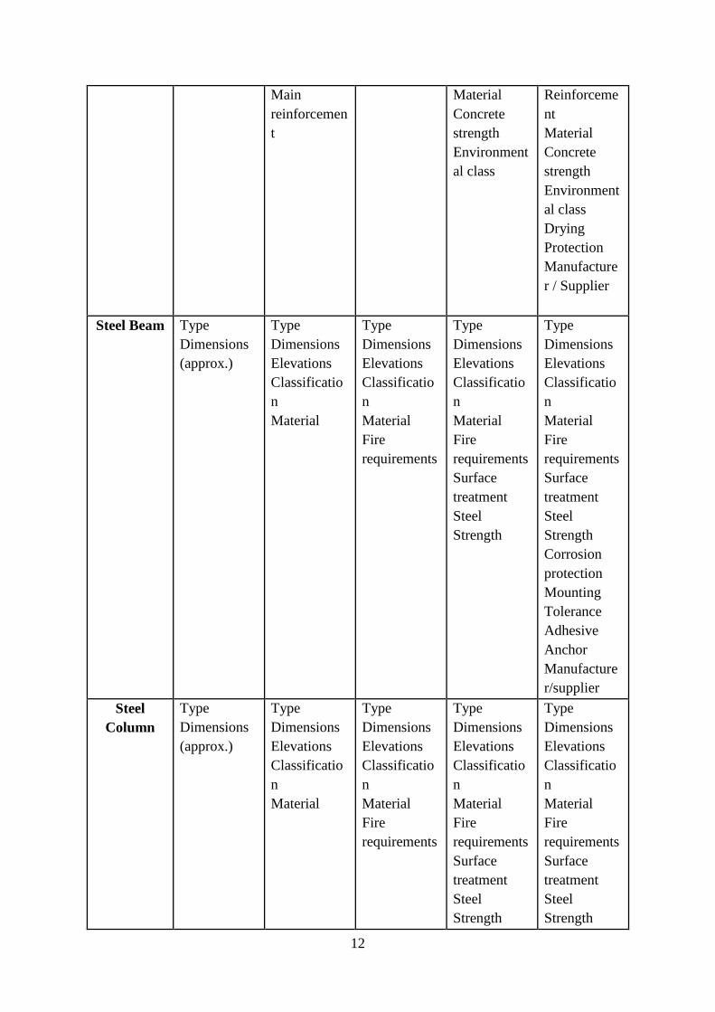
2.3 Data transfer requirement
Table 2.2 represents the information required for various structural elements at different LOD. As the
LOD gets higher the granularity of data also increases.
Structural
Element
Information Required
LOD 100 LOD 200 LOD 300 LOD 350 LOD 400
Foundation Type
Dimensions
(approx.)
Type
Dimensions
Elevation
Classificatio
n
Materials
Type
Dimensions
Elevation
Classificatio
n
Materials
Reinforceme
nt degree
Type
Dimensions
Elevation
Classificatio
n
Materials
Reinforceme
nt
Concrete
strength
Environment
al class
Blinding
layer
Concrete
Type
Dimensions
Elevation
Elevation
Tolerances
Classificatio
n
Materials
Reinforceme
nt
Concrete
strength
Environment
al class
Blinding
layer
concrete
Water
proofing
Density
Manufacture
r / Supplier
Concrete
Slab
Type
Dimensions
(approx.)
Type
Dimensions
Elevations
Classificatio
n
Type
Dimensions
Elevations
Classificatio
n
Type
Dimensions
Elevations
Classificatio
n
Type
Dimensions
Elevations
Elevation
tolerances
Page 21
11
Material Material Material
Main
reinforcemen
t
Concrete
strength
Environment
al class
Classificatio
n
Material
Reinforceme
nt
Concrete
strength
Environment
class
Weight
Drying
Protection
Manufacture
r / Supplier
Concrete
Beam
Type
Dimensions
(approx.)
Type
Dimensions
Elevations
Classificatio
n
Material
Type
Dimensions
Elevations
Classificatio
n
Material
Type
Dimensions
Elevations
Classificatio
n
Material
Main
reinforcemen
t
Concrete
strength
Environment
al class
Type
Dimensions
Elevations
Elevation
tolerances
Classificatio
n
Material
Reinforceme
nt
Concrete
strength
Environment
al class
Drying
protection
Reinforced
joints
Concrete
joints
Manufacture
r / Supplier
Concrete
Column
Type
Type
Dimensions
(approx.)
Elevations
Classificatio
n
Type
Dimensions
Elevations
Classificatio
n
Reinforceme
nt degree
Material
Type
Dimensions
Elevations
Classificatio
n
Main
reinforcemen
t
Type
Dimensions
Elevations
Elevation
tolerances
Classificatio
n
Page 22
12
Main
reinforcemen
t
Material
Concrete
strength
Environment
al class
Reinforceme
nt
Material
Concrete
strength
Environment
al class
Drying
Protection
Manufacture
r / Supplier
Steel Beam Type
Dimensions
(approx.)
Type
Dimensions
Elevations
Classificatio
n
Material
Type
Dimensions
Elevations
Classificatio
n
Material
Fire
requirements
Type
Dimensions
Elevations
Classificatio
n
Material
Fire
requirements
Surface
treatment
Steel
Strength
Type
Dimensions
Elevations
Classificatio
n
Material
Fire
requirements
Surface
treatment
Steel
Strength
Corrosion
protection
Mounting
Tolerance
Adhesive
Anchor
Manufacture
r/supplier
Steel
Column
Type
Dimensions
(approx.)
Type
Dimensions
Elevations
Classificatio
n
Material
Type
Dimensions
Elevations
Classificatio
n
Material
Fire
requirements
Type
Dimensions
Elevations
Classificatio
n
Material
Fire
requirements
Surface
treatment
Steel
Strength
Type
Dimensions
Elevations
Classificatio
n
Material
Fire
requirements
Surface
treatment
Steel
Strength
Page 23
13
Corrosion
protection
Mounting
tolerance
Adhesive
anchor
Semi/drilling
depth
Manufacture
r/Supplier
Table 2.2: Information required for various structural elements at different LOD
Page 24
14
3. Data sharing model
Data interoperability is a key to achieving worldwide standardization of BIM methods and
usage. An open-source approach based on open standards and workflows is called OpenBIM.
Open data standards achieve common language and empower the exchange of relevant data
between software applications and thus an efficient communication among project members.
Every standard is based on 3 main components - Terminology, Process and Digital storage.
Figure 3.1: buildingSMART standards triangle
buildingSMART has developed an open standard for BIM, known as IFC and is registered as
ISO 16739. The standard deals with data models, processes and terms. buildingSMART has also
published some other types of open standards to support IFC, they are
IFD: International Framework for Dictionaries (ISO 12006-3, 2007)
IDM: Information Delivery Manual (ISO: 29481 – Part 1 &2, 2016)
MVD: Model View Definitions
BCF: BIM Collaboration Frame-work
IFC is a standardized, digital description of the built environment, including buildings and civil
infrastructure. It is a vendor-neutral and usable across a wide range of hardware devices and
software platforms. The schema specification describes how a facility or installation is, used,
constructed and operated. IFC can define physical components of buildings, manufactured
products, mechanical/electrical systems, as well as more abstract structural analysis models,
energy analysis models, cost breakdowns, work schedules and many other things. IFC can also
be used as a means of archiving project information, whether incrementally during the design,
procurement, and construction phases, or as an "as-built" collection of information for long-
term preservation and operations phases [17].
3.1 IFC Schema
A schema is ‘a collection of entities (or classes), attributes, and relationships between entities’.
The IFC specification includes terms, concepts and data specification items that originate from
use within disciplines, trades, and professions of the construction and facility management
Page 25
15
industry sector. The IFC specify a data schema and an exchange file format structure. The data
schema is defined in
EXPRESS data specification language as defined in ISO 10303-11
XML Schema definition language (XSD) as defined in ISO 10303-28
The IFC data schema architecture is defined in four conceptual layers, each individual schema
is assigned to exactly one conceptual layer.
Figure 3.2: IFC data schema conceptual layer
1. Resource layer: It is the lowest layer which includes all individual schemas containing
resource definitions, these definitions do not include a globally unique identifier and shall
not be used independently of a definition declared at a higher layer.
2. Core layer: This layer includes the kernel schema and the core extension schemas,
containing the most general entity definitions, all entities defined at the core layer, or above
carry a globally unique id and optionally owner and history information.
Page 26
16
3. Interoperability layer: This layer includes schemas containing entity definitions that are
specific to a general product, process or resource specialization used across several
disciplines, those definitions are typically utilized for inter-domain exchange and sharing
of construction information.
4. Domain layer: This is the highest layer includes schemas containing entity definitions that
are specializations of products, processes or resources specific to a certain discipline, those
definitions are typically utilized for intra-domain exchange and sharing of information.
In Ifc schema all the data item names for types, entities, rules and functions start with the prefix
"Ifc" while the attribute names within an entity has no prefix; the property set definitions start
with prefix "Pset_" and the quantity set definitions start with the prefix "Qto_". All the Ifc
entities originate from IfcRoot, the common super type of all IFC entities, except those defined
in an IFC resource schema. It is the most abstract and root class for all entity definitions that
roots in the kernel or in subsequent layers of the IFC specification. All entities that are subtypes
of IfcRoot can be used independently, whereas resource schema entities, that are not subtypes
of IfcRoot, are not supposed to be independent entities. The three fundamental sub types of
IfcRoot are IfcObjectDefinition, IfcPropertyDefinition and IfcRelationship.
IfcObjectDefinition is the generalization of any semantically treated thing or process, which
can be either a type or an occurrence. Object definitions can be named by means of the inherited
Name attribute, which should be a user recognizable label for the object occurrence. The
principle sub types of IfcObjectDefinition are IfcContext, IfcObject and IfcTypeObject.
IfcPropertyDefinition defines the generalization of all characteristics (i.e. grouping of
individual properties), that may be assigned to objects. At present, sub types of
IfcPropertyDefinition include property set occurrences, property set templates, and property
templates. IfcPropertySetDefinition and IfcPropertyTemplateDefinition are sub types of
IfcPropertyDefinition.
IfcRelationship is essentially the abstract generalization of all objectified relationships in IFC.
Objectified relationships has the priority when it comes to handling relationships among
objects. This allows to keep relationship specific properties directly at the relationship and
opens the possibility to later handle relationship specific behavior. IfcRelAssigns,
IfcRelAssociates, IfcRelConnects, IfcRelDeclares, IfcRelDecomposes and IfcRelDefines.
3.2 Model View Definition (MVD)
MVD is a subset of the overall IFC schema to describe a data exchange for a specific purpose
or workflow as it narrows the broad scope depending on the need of the receiver. MVDs are
data-centric rather than application-centric. Not every domain expert in a project need all the
same information delivered or received. So, there's a need to clarify which subset of all the
data, and its format, is needed to exchange for a particular use. A MVD will describe which
objects, representations, relationships, concepts, and attributes are needed for the receiving
Page 27
17
stakeholder and their software application to accomplish a desired task. In a MVD, the
following is defined for the replacement process of an IFC model:
How information is exchanged
The data standard
Required configurations for the standard
buildingSMART developed 6 MVDs for specific purpose within the AEC industry and 4 more
are in draft stage. Some examples of MVDs are
Architectural Design to Structural Design: The architect provides the structural engineer a
model "background" that can be referenced for the placement and design of structural elements.
Architectural Design to Quantity Takeoff: The architect provides the general contractor a model
that has accurate element placement extents for extracting quantities and assigning costs.
Building Envelope Design to Energy Analysis: The architect provides the energy consultant a
model with specific construction types and material thermal values, as well as thermal comfort
values for internal spaces to determine building performance
Construction Operations Building Information Exchange (COBie): The contractor provides as-
built data to the owner and facility manager for operations [18].
3.3 Structural data in IFC
This section describes the information and entities required to represent the structural data in
the IFC schema and establishes relation with each other using relationship entities. The
Information required to develop the open BIM data model for structural engineering domain
(Lead designer to specific task members) is divided into 7 essential parts as shown below
1. Static analysis
2. Dynamic analysis
3. Probabilistic analysis
4. Finite element analysis
5. Pre-Stressed Concrete
6. Steel connection design
7. Reinforcement detailing
Static Analysis: The IfcStructuralAnalysisDomain describes the structural analysis model in
order to tightly integrate the structural engineering domain. It reuses the existing building
element and spatial structure element definition and associates the structural assumptions to it.
The focus is to ensure that structural engineering information is captured and made visible to
other related domains.
Dynamic analysis, Probabilistic analysis, Finite element analysis and Pre-Stressed Concrete:
There are no entities in IFC that describe parameters for the above analysis methods. These
analysis methods can be added as an extension of an IFC model using Property Sets. A Property
set is used to define dynamically expandable attributes. It is a container class that represents
Page 28
18
the attributes within a schema includes. The interpretation of the attributes is done according
to their name. Suitable entity would be IfcStructuralLoad for load effect.
3.3.1 Structural elements
The schema IfcStructuralElementsDomain provides the ability to represent different kinds of
building elements and parts which in general are of structural in nature. In addition to
commonly used building elements defined in IfcSharedBuildingElements schema, it contains
entities for foundation parts such as footings and piles. It also contains some important
structural subpart such as different kinds of explicit reinforcement parts, and manufactured
features and treatments.
IfcFooting: A footing is a part of the foundation of a structure that spreads and transmits the
load to the soil. A footing is also characterized as shallow foundation, where the loads are
transferred to the ground near the surface.
IfcReinforcingBar: A reinforcing bar is usually made of steel with manufactured deformations
on the surface, and used in concrete and masonry construction to provide additional strength.
A single instance of this class may represent one or many of actual rebars, for example a row
of rebars.
The building element comprises all elements that are primarily part of the construction of a
built facility, i.e., its structural and space separating system. Building elements are all
physically existent and tangible things. An element is a generalization of all components that
make up an AEC product. Elements are physically existent objects, although they might be
void elements, such as holes/recesses. They can either remain permanently or temporarily such
as formwork and they can be either assembled on site or pre-manufactured. An element can
have material and quantity information which can be assigned through
IfcRelAssociatesMaterial and IfcRelDefinesByProperties relationship. Elements are a sub set
of IfcBuildingElement which is a sub set of IfcElement. The various structural elements in Ifc
are
IfcBeam: An IfcBeam is a horizontal, or nearly horizontal, structural member that is capable
of withstanding load primarily by resisting bending. It represents such a member from an
architectural point of view. It is not required to be load bearing.
IfcColumn: IfcColumn is a vertical structural member which often is aligned with a structural
grid intersection. It represents a vertical, or nearly vertical, structural member that transmits,
through compression, the weight of the structure above to other structural elements below. It
represents such a member from an architectural point of view. It is not required to be load
bearing.
IfcSlab: A slab is an element that may enclose a space vertically. The slab may provide the
lower support (floor) or upper construction (roof slab) in any space in a building. Only the core
(Structural part) is considered as slab, the upper finish (flooring, roofing) and the lower finish
(ceiling, suspended ceiling) are considered to be coverings. There is also a representation of
slabs for structural analysis provided by a proper subtype of IfcStructuralMember being part
of the IfcStructuralAnalysisModel. An arbitrary planar element to which this semantic
Page 29
19
information is not applicable shall be modeled as IfcPlate. A slab may have openings, such as
floor openings, or recesses. They are defined by an IfcOpeningElement attached to the slab
using the inverse relationship HasOpenings pointing to IfcRelVoidsElement.
3.3.2 Geometry and placement
The schema IfcGeometryResource defines the resources used for geometric representations.
The primary application of this resource is for representation of the shape or geometric form
of an element. The geometric representation items can also be used to describe geometric
models within the schema IfcGeometricModelResource.
The schema IfcGeometricConstraintResource is used to determine the placement of the shape
representation of a product within the geometric representation context of a project. It also
contains resource definitions to be assigned to product connectivity definitions to determine
the connection geometry constraints between those products.
The primary application of this resource is to:
determine the object placement used for the shape representation of the object
determine the constraints applied to the connectivity between two shapes of objects
The placement of a product's shape is given by the IfcObjectPlacement, used by the
attribute ObjectPlacement of IfcProduct. The object placement defines the local object
coordinate system in which all shape representations of that product are defined. It is given
either as
Absolute placement: It is specified by using IfcLocalPlacement and omitting the
PlacementRelTo attribute.
Relative placement: It is specified by using IfcLocalPlacement and pointing the
PlacementRelTo attribute to an IfcObjectPlacement used in another IfcProduct instance.
Placement relative to a grid: It is specified by using IfcGridPlacement pointing to one (or two)
virtual intersections of IfcGridAxis. If two virtual intersections are references, than the second
virtual intersections specifies the orientation of the object placement. Alternatively the
direction can also be provided explicitly by ifcDirection.
An IfcStructuralConnection represents a structural connection object (node connection, edge
connection, or surface connection) or supports. There are 3 types of Connections supported
Point connections: Defined by IfcStructuralPointConnection
Curve connections: Defined by IfcStructuralCurveConnection
Surface connections: Defined by IfcStructuralSurfaceConnection
Page 30
20
3.3.3 Loads definitions
The entity IfcStructuralActivity represents the definition of actions (such as forces,
displacements, etc.) and reactions (support reactions, internal forces, deflections, etc.) which
are specified by using the basic load definitions from the IfcStructuralLoadResource.
The differentiation between actions and reactions is realized from the
subclasses IfcStructuralAction or IfcStructuralReaction respectively. They inherit commonly
needed attributes from the abstract superclass IfcStructuralActivity, notably the relationship
which connects actions or reactions with connections, analysis members, or elements (subtypes
of IfcStructuralItem or IfcElement).
The entity IfcStructuralLoadGroup is used to structure the physical impacts. By using the
grouping features inherited from IfcGroup, instances of IfcStructuralAction (or its subclasses)
and of IfcStructuralLoadGroup can be used to define load groups, load cases and load
combinations.
3.3.4 Material definitions
IfcMaterial is a homogeneous or inhomogeneous material that can be used to form elements
(physical elements or their components). IfcMaterial is the basic entity for material designation
and definition; this includes identification by name and classification as well as association of
material properties (isotropic or anisotropic) defined by subtypes of IfcMaterialProperties. An
instance of IfcMaterial may be associated to an element or element type using
the IfcRelAssociatesMaterial relationship. The assignment might either be direct as a single
material information, or a material in layer, profile and constituent sets.
An IfcMaterial may also have presentation information associated. Such presentation
information is provided by IfcMaterialDefinitionRepresentation, associating curve styles,
hatching definitions or surface coloring/rendering information to a material.
3.3.5 Structural Results
The entity IfcStructuralResultGroup is used to group results of structural analysis calculations
and to capture the connection to the underlying basic load group. The basic functionality for
grouping inherited from IfcGroup is used to collect instances from IfcStructuralReaction or its
respective subclasses.
A structural reaction is a structural activity that results from a structural action imposed to a
structural item or building element. Examples are support reactions, internal forces, and
deflections. Structural reactions are grouped into IfcStructuralResultsGroups via the inverse
relationship HasAssignments and an IfcRelAssignsToGroup relationship object.
Page 31
21
It is also possible to establish relationships between reactions in one analysis model and actions
which they cause into another analysis model. For example, a support reaction from one
structural system may be taken over as a load onto another supporting structural system. This
is expressed by means of the inverse relationship HasAssignments of the reaction and
an IfcRelAssignsToProduct relationship object.
Page 32
22
4. Demonstration of data sharing
To demonstrate the data sharing between a BIM tool and a structural engineering software for
structural analysis and design using IFC as an interoperable file format, a suitable composite
structural model is selected. The purpose is to investigate the following,
Level of data sharing (Data Quality) between BIM tool and a structural engineering
software based on the data requirements for structural analysis and design.
Adoption or implementation of meta-model data schemas in a BIM tool (Revit) for data
export.
Capability or adaptability of structural engineering software to import the data from IFC
file format.
Aanalysis and identification of modelling errors in the BIM model by using Model Viewer
tools.
The BIM model is created using Autodesk Revit 2018 and this model is then imported to
structural engineering software (SCIA Engineer Version 18.1) which supports import of IFC4
data schemas. The following steps are carried out for demonstration of data sharing and to
investigate the information mentioned above,
1. A detailed description of data transfer methodology.
2. A complete description of modelled data in Revit.
3. Verification of exported data from Revit to IFC using model view checkers.
4. Guidelines for the successful implementation of data transfer to SCIA Engineer.
5. Investigation of data in SCIA Engineer, which is imported from IFC.
4.1 Research Methodology
The work flow adopted is explained as follows:
1. Firstly, the model is created using the Autodesk Revit 2018 software (Student version).
Revit is chosen as a BIM modelling tool as it supports export of data in IFC4 format.
The generated model is then exported to IFC file formats (meta-data model schemas).
In this work IFC4 – Addendum 2 (IFC4 ADD2) version of OpenBIM standards
published in July-2016 is used.
2. Then the model is exported as IFC file format from Revit software. Now, before
importing the IFC file to SCIA Engineer, the model is checked by model checkers (In
this work FZKViewer-5.2_Build-992 is used, developed by Karlsruhe Institute of
Technology which is available freely). In the model checker, the model is investigated
for any error or missing entities or issues. In case of any bug, the findings are reported
and the model is sent back to Revit for further modifications. This helps the user to
rectify the modelling errors in the initial stage of the data sharing process.
Page 33
23
3. Now, the IFC file (verified by model checker) is imported to SCIA Engineer software
for structural analysis and design. Further verifications regarding the data quality and
correctness are performed in SCIA.
Figure 4.1 represents the methodology (the sequence of operations) for data sharing between Revit
and SCIA.
Figure 4. 1: Sequence of operations for demonstration of data sharing
4.2 Revit Model
A three-storey composite structural model is considered for the demonstration of data transfer
between Revit and SCIA. The structure is modelled in Revit and geometry is assigned to all
structural elements like foundations, beams, columns and slabs. The foundations and first
storey is made up of concrete (foundations, beams, columns and slab). The second and third
storey is made up of steel (beams, columns and slab). Rectangular steel tube is used for column
and I-Sections is used for beams and solid steel plate is used for slab. The structure consists of
three bays, the first two consist of floor slabs along with cantilever on one side, while the last
one is for stair case hosting. The model is constructed in Revit by using different Revit families.
Relevant or similar families are used to construct different building components like beams,
columns, slabs, etc. and all these components are interconnected to avoid gaps and overlaps.
Revit provides a number of default constructions for each building component, but it also
allows the user to define own material, properties, layers and thickness. Figure 4.2 shows the
model developed in Revit.
Page 34
24
Figure 4. 2: Three Storey composite structure - Revit model
The model is composed of both rectangular and circular columns and beams of various depths
are incorporated into the model. A cantilever is also used in the model. The model takes into
account the shape and dimensions of various structural elements. Table 4.1 provides a summary
of various structural elements modelled in Revit.
Structural Element Dimention (L×B×H/D in
mm)
Material
Foundation 1200×900×400 Concrete (25 Mpa)
Beam - 01 300×400 Concrete (25 Mpa)
Page 35
25
Beam - 02 400×500 Concrete (25 Mpa)
Beam - 03 400×400 Concrete (25 Mpa)
Beam - 04 300×500 Concrete (25 Mpa)
Beam - 05 ISMB 250 Steel (345 Mpa)
Beam - 06 ISMB 300 Steel (345 Mpa)
Beam - 07 ISMB 400 Steel (345 Mpa)
Cross Beam (Steel Angle) 50×50×6 Steel (345 Mpa)
Column -01 400×300 Concrete (25 Mpa)
Column -02 300×200×7 (Rect. Hollow
Sec.)
Steel (345 Mpa)
Column -03 200×200×14.2 (I Sec.) Steel (345 Mpa)
Table 4. 1: Construction details of structural elements
4.2 IFC export
Revit offers customized IFC export setup options. Figure 4.3 represents the export parameters
mentioned in Revit for IFC export. Based on this parameters Revit will export the modelled
data to IFC file. The export parameters are divided into different categories. They are as follows
General
Additional content
Property sets
Level of detail
Advanced
Figure 4. 3: Export parametres in Revit for IFC
Each category has its own importance in the export process, but the General category plays a
key role in the export process because it contains information regarding model view, space
boundary, and project location and construction phase details. Generally, IFC 4 is equipped
Page 36
26
with two View Definitions, Design Transfer View (DTV) and Reference View (RV). Design
Transfer View allows more entities (such as frame and lining de-tails for doors and windows)
for transfer between tools when compared to Reference View, and DTV supports the editing
of the IFC file. For IFC export process, Design Transfer View (DTV) is used as Model View
Definition.
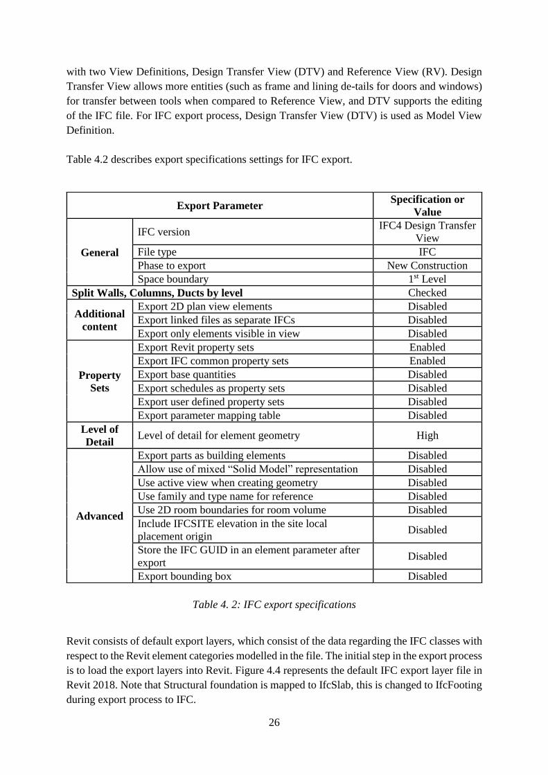
Table 4.2 describes export specifications settings for IFC export.
Table 4. 2: IFC export specifications
Revit consists of default export layers, which consist of the data regarding the IFC classes with
respect to the Revit element categories modelled in the file. The initial step in the export process
is to load the export layers into Revit. Figure 4.4 represents the default IFC export layer file in
Revit 2018. Note that Structural foundation is mapped to IfcSlab, this is changed to IfcFooting
during export process to IFC.
Export Parameter Specification or
Value
General
IFC version IFC4 Design Transfer
View
File type IFC
Phase to export New Construction
Space boundary 1st Level
Split Walls, Columns, Ducts by level Checked
Additional
content
Export 2D plan view elements Disabled
Export linked files as separate IFCs Disabled
Export only elements visible in view Disabled
Property
Sets
Export Revit property sets Enabled
Export IFC common property sets Enabled
Export base quantities Disabled
Export schedules as property sets Disabled
Export user defined property sets Disabled
Export parameter mapping table Disabled
Level of
Detail Level of detail for element geometry High
Advanced
Export parts as building elements Disabled
Allow use of mixed “Solid Model” representation Disabled
Use active view when creating geometry Disabled
Use family and type name for reference Disabled
Use 2D room boundaries for room volume Disabled
Include IFCSITE elevation in the site local
placement origin Disabled
Store the IFC GUID in an element parameter after
export Disabled
Export bounding box Disabled
Page 37
27
After finishing the IFC-export set up the process, the modelled data has been exported to IFC
(STEP – physical file format) file and the same file imported to the Model viewer tool to verify
the data quality and modelling errors. The exported IFC file is attached in Appendix A for
reference.
Figure 4. 4: IFC export Layers mentioned in Revit 2019
4.3 Verification (FZKViewer)
After successfully exporting the model from Revit into IFC format. The IFC file is checked
into model viewers for modelling errors. Figure 4.4 gives a summary of entities and relations
exported in to IFC file format. It can be seen that there are a total number of 8 footings, 78
beams, 32 columns and 3 slabs are exported. Figure 4.5 shows the model as interpreted by FZK
model viewer. On examining the entities it can be seen that there is some problem with beam
connected to circular column. Figure 4.6 shows the zoomed view of the problem. Other
geometry and dimension of structural elements are found to be exported correctly. The beam
to circular column connection error is noted and the circular column is replaced with
rectangular column. Now, the model is modified with rectangular column in place of circular
column in Revit and is again exported to IFC and checked into FZK model viewer (Figure 4.7)
and found correct.
Page 38
28
Figure 4. 5: Summary of entities and Relations
Figure 4. 6: IFC model in FZK viewer
Page 39
29
Figure 4. 7: Connection of beam to circular column error
Figure 4. 8: Circular column is replaced with rectangular column - Revit Model
Page 40
30
Figure 4. 9: Circular column is replaced with rectangular column - FZK Viewer
4.4 Import to SCIA Engineer
After verification of the quality of input data using Model Viewer tool, the data has been
transferred to SCIA Engineer. This section investigates the data import capabilities of SCIA
from IFC and the quality of imported data. SCIA gives an import statistics after every
successful import IFC file. When the IFC file is imported with circular columns it is unable to
read beams connecting to that column, SCIA shows the error as missing or unsupported
geometry.
After replacing circular columns with rectangular columns, the model is again imported into
SCIA software. Figure 4.9 shows the import statistics of SCIA engineer with rectangular
columns. Note that SCIA has replaced Revit exported materials with their default one. However
there is no error with import of any entities.
Page 41
31
Figure 4. 10: Import statistics of SCIA engineer (With circular columns)
Figure 4. 11: Import statistics of SCIA engineer (With rectangular columns)
The structural analysis in SCIA is carried out using analytical model. Figure 4.10 shows the
model imported into SCIA. It can be seen that SCIA has converted into analytical model. The
nodes can be seen disjointed. When load is applied over the structure and stability analysis is
carried out it gives the result, that structure is unstable in vertical direction. This is due to the
fact that nodes are not joined at one point.
Page 42
32
Figure 4. 12: Imported model into SCIA (Analytical Model)
Page 43
33
5. Results and Discussions
The results analysis is carried out to explain the data quality and the interoperability problems
between the BIM tool and structural analysis software.
The first problem was found in default export layers of Revit for IFC data transfer, the Revit
element structural foundation was mapped to IfcSlab by default in export layer, which was
modified to IfcFooting.
The second problem was found in connection of rectangular concrete beam to circular concrete
column. Revit IFC manual describes three basic possibilities for Geometric representation of
three-dimensional IFC objects as:
extrusions
solid body representation using a sweep, and
representation using B-reps
B-rep: The method known as boundary representation (B-rep) can also be described as a
boundary surface model. The surfaces of a component are represented using coordinates and
together form the actual solid, allowing even complex forms to be represented.
B-rep objects use complex calculations to represent individual surfaces in detail.
NURBS and other smooth surfaces
In the IFC4 schema, it is possible to generate B-rep objects as advanced B-reps using NURBS
(non-uniform rational B-splines) surfaces. The bodies are represented more accurately.
The IFC4 documentation describes an entity called IfcAdvancedBrep under
IfcGeometricModelResource in the Resource definition data schemas. The entity is defined as,
an advanced B-rep is a boundary representation model in which all faces, edges and vertices
are explicitly represented. It is a solid with explicit topology and elementary or free-form
geometry. The faces of the B-rep are of type IfcAdvancedFace. An advanced B-rep has to meet
the same topological constraints as the manifold solid B-rep. The advanced B-rep has been
introduced in order to support the increasing number of applications that can define and
exchange B-rep models based on NURBS or other b-spline surfaces.
In our model, on examining the ifcxml file it was found to use IfcAdvancedBrep for model
geometry. Note that typically software supporting IFC only implement model view definitions
a subset of IFC. So, the shape representation we are trying is not recognizing as it's beyond the
model view definition, or perhaps they just don't recognize IfcadvancedBrep at all in IFC4
ADD2 DTV. Also there is no documentation available for IFC4 DTV to verify for
IfcadvancedBrep. DTV is summarized as on building smart website as “Advanced geometric
and relational representation of spatial and physical components to enable the transfer of model
information from one tool to another. Not a "round-trip" transfer, but a higher fidelity one-way
Page 44
34
transfer of data and responsibility”. However, the documentation available for IFC4 RV
doesn’t contain IfcadvancedBrep.
The third problem was found in SCIA software. SCIA uses analytical models for structural
analysis. After importing the model into SCIA the nodes are found to be disjointed. This is due
to SCIA has taken end to end distance as centre line of member for creating analytical model.
Due to this at junctions all member ends doesn’t joins at one point. And when structural
analysis is carried out it give the result the structure is unstable.
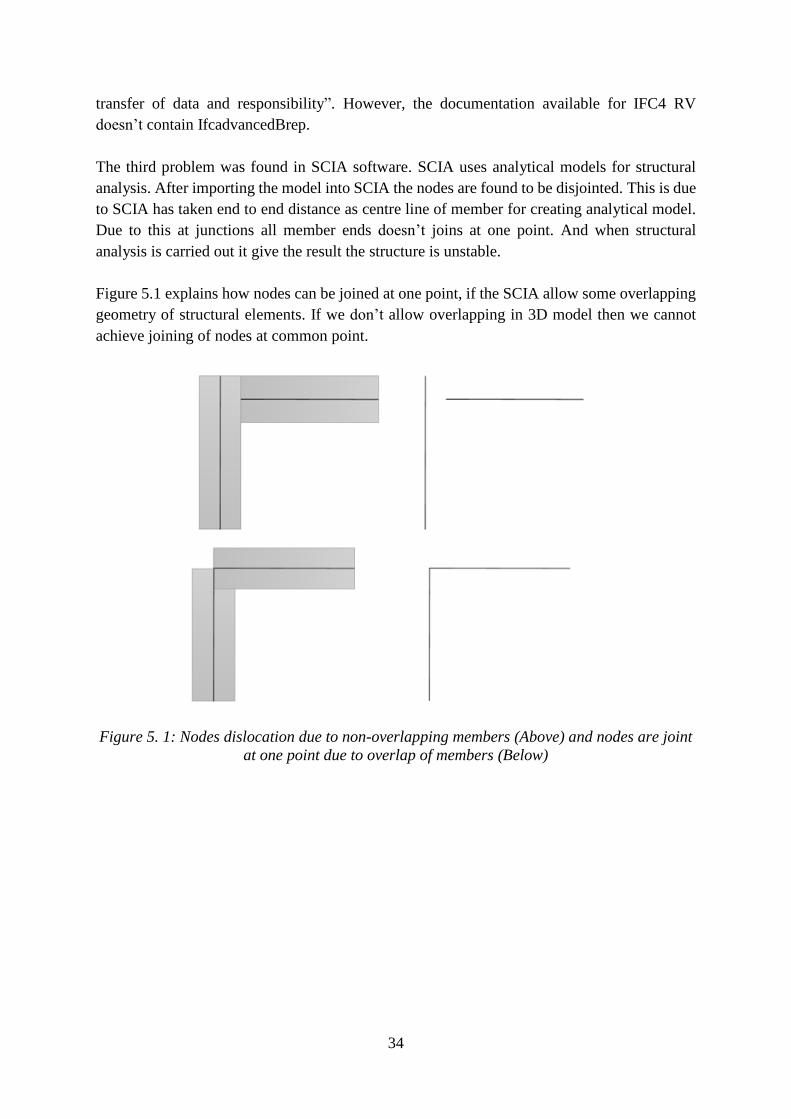
Figure 5.1 explains how nodes can be joined at one point, if the SCIA allow some overlapping
geometry of structural elements. If we don’t allow overlapping in 3D model then we cannot
achieve joining of nodes at common point.
Figure 5. 1: Nodes dislocation due to non-overlapping members (Above) and nodes are joint
at one point due to overlap of members (Below)
Page 45
35
6. Conclusions and Outlook
Page 46
36
References
[1] G. v. Nederveen and F. Tolman, "Modelling multiple views on buildings," Automation
in Construction, pp. 215-224, 1992.
[2] “National Institute of BUILDING SCIENCES,” National BIM Standard - United
States, [Online]. Available: https://www.nationalbimstandard.org/faqs. [Accessed 09
September 2019].
[3] V. Caffi, “REPRESENTING THE ARCHITECTURAL PROJECT: AN
EDUCATIONAL CAAD PROGRAM FOR BUILDING ENGINEERING AND
ARCHITECTURE MSC CURRICULUM,” Milano, 2009.
[4] “https://en.wikipedia.org/wiki/Building_information_modeling#cite_note-19,”
[Online]. Available: https://www.wikipedia.de/. [Accessed 09 September 2019].
[5] M. P. Gallaher, A. C. O'Connor, J. L. Dettbarn, Jr. and L. T. Gilday, “Cost Analysis of
Inadequate Interoperability in the U.S. Capital Facilities Industry,” National Institute of
Standards and technology, Maryland, 2004.
[6] D. A. Harris, “NATIONAL BUILDING INFORMATION MODELING
STANDARD,” National Institute of BUILDING SCIENCES, 2007.
[7] H. LAI and X. DENG, “INTEROPERABILITY ANALYSIS OF IFC-BASED DATA
EXCHANGE BETWEEN HETEROGENEOUS BIM SOFTWARE,” Journal of Civil
Engineering and Management, vol. 24, no. 7, pp. 537-555, 2018.
[8] Y.-S. Jeong, C. Eastman, R. Sacks and I. Kaner, “Benchmark tests for BIM data
exchanges of precast concrete,” Automation in Construction, vol. 18, pp. 469-484,
2009.
[9] P.-H. Chen, L. Cui, C. Wan, Q. Yang, S. K. Ting and R. L. Tiong, “Implementation of
IFC-based web server for collaborative building design between architects and
structural engineers,” Automation in Construction, vol. 14, pp. 115-128, 2004.
[10] A. Redmond, A. Hore, M. Alshawi and R. West, “Exploring how information
exchanges can be enhanced through Cloud BIM,” Automation in Construction, vol. 24,
pp. 175-183, 2012.
[11] Q. Ling, D. Xue-yuan and L. Xi-la, “Industry Foundation Classes Based Integration of
Architectural Design and Structural Analysis,” J. Shanghai Jiaotong Univ. (Sci.), vol.
16, no. 1, pp. 83-90, 2011.
[12] E. Mavreli, “Level of Development vs Level of Detail for BIM,” TUM, Munich, 2018.
[13] AIA Document G202-2013, Project Building Information Modeling Protocol Form,
American Institute of Architects, 2013.
[14] J. Bedrick and J. Reinhardt, LEVEL OF DEVELOPEMENT (LOD) SPECIFICATION
PART I & COMMENTARY, BIMForum, 2019.
[15] “https://www.gsa.gov/real-estate/design-construction/3d4d-building-information-
modeling/guidelines-for-bim-software/document-guides/level-of-detail,” [Online].
Available: https://www.gsa.gov/. [Accessed 11 09 2019].
Page 47
37
[16] Guide, Instructions and Commentary to the 2013 AIA Digital Practice Documents,
American Institute of Architects, 2013.
[17] “buildingSMART International,” [Online]. Available:
https://technical.buildingsmart.org/standards/ifc/. [Accessed 18 09 2019].
[18] “buildingSMART International,” [Online]. Available:
https://technical.buildingsmart.org/standards/mvd/. [Accessed 18 09 2019].
[19] X. Wang, Z. Cui, Q. Zhang and H. Yang, “Creating Structural Analysis Model From
IFC-Based Structural Model,” Advanced Materials Research, Vols. 712-715, pp. 901-
904, 2013.
[20] G. Popgavrilova, “BIM and the public sector,” TUM, Munich, 2018.
[21] “gbXML,” [Online]. Available:
http://www.gbxml.org/About_GreenBuildingXML_gbXML. [Accessed 18 09 2019].
[22] “LandXML.org,” [Online]. Available: http://www.landxml.org/About.aspx. [Accessed
19 09 2019].
[23] “OGC,” [Online]. Available: https://www.opengeospatial.org/standards/citygml.
[Accessed 19 09 2019].
[24] “Wikipedia,” [Online]. Available: https://en.wikipedia.org/wiki/CityGML. [Accessed
19 09 2019].
[25] “GISWIKI,” [Online]. Available: http://giswiki.org/wiki/LandXML. [Accessed 19 09
2019].
[26] “European Construction Sector Obsevatory,” 2018.