Quality of Service in the Point-to-Point Protocol over Ethernet Master of Science Thesis in Electrical Engineering Stockholm, October 2000 Author: Patrik Lahti Kungl Tekniska Högskolan Royal Institute of Technology Examiner: Björn Pehrson, KTH Supervisors: Fredrik Roos and Stefan Sandell, Telia Research
Transcript
Quality of Service in the Point-to-Point Protocol over Ethernet
Master of Science Thesis in Electrical Engineering
Stockholm, October 2000
Author: Patrik Lahti Kungl Tekniska Högskolan Royal Institute of Technology
Examiner: Björn Pehrson, KTH
Supervisors: Fredrik Roos and Stefan Sandell, Telia Research
Quality of Service in the Point-to-Point Protocol over Ethernet II
Quality of Service in the Point-to-Point Protocol over Ethernet III
Abstract Broadband IP access is expected to receive extensive deployment
within the private consumer market, bringing new services to its subscribers in the near future. These new services have specific demands on treatment of traffic, such as those on timeliness and limited loss, beyond the traditional Best Effort service. Hence, Quality of Service provisioning is increasingly becoming mandatory for a network operator in the broadband access market.
This Master’s project has focused on QoS issues of a broadband access based on Point-to-Point Protocol over Ethernet. It investigates how QoS can be provided in this architecture and determines its stability and performance.
During the project it was concluded that QoS can be provided in the broadband access in several ways. No amendments or additions to PPPoE or PPP standards are needed, and it is recommended that IP Differentiated Services Field should be statically mapped to Ethernet priorities. Also, it was found that the PPPoE architecture copes well with packet loss, delay, reordering and duplication often encountered in QoS enabled networks. However, some improvements can be made to optimise and further stabilise its operation.
Further, the PPPoE architecture is found to perform well, only slightly worse than expected if only considering additional packet overhead. Some recommendations for further studies in the area are proposed.
Sammanfattning Bredband har blivit ett begrepp på den svenska marknaden och
utbyggnaden av bredbandsnät och husnät är i full gång. Bredband förväntas inte bara ge sina kunder snabb Internetåtkomst utan också nya tjänster. Dessa tjänster ställer krav på hur nätet behandlar traffik, till exempel vilka paketfördröjningar och förluster som kan accepteras. Därför blir det livsviktigt för nätoperatörer att tillhandage tjänstekvalite (QoS) i sina nät.
Detta examensarbete har fokuserat på tjänstekvalite i en bredbandsaccess baserat på protokollet PPPoE. Arbetet har undersökt hur tjänstekvalite kan tillhandahållas i denna arkitektur och lösningens stabilitet och prestanda.
Som slutsats gavs att QoS kan erbjudas genom flera metoder. Det rekommeras att IP prioriteter statiskt mappas till Ethernet prioriteter. Då blir heller inga förändringar i PPP eller PPPoE standarder nödvändiga. Man fann också att arkitekturen beter väl under paketförluster, fördröjningar samt duplicering och ordning av paket. Dock kan förbättringar och optimeringar av implementationerna vara på sin plats. Det fanns att PPPoEs presterade väl och endast något sämre än förväntat med tanke på de extra pakethuvudena. Slutligen presenteras förslag på framtida studier inom området.
Quality of Service in the Point-to-Point Protocol over Ethernet IV
Quality of Service in the Point-to-Point Protocol over Ethernet V
Keywords Broadband access
QoS – Quality of Service
CoS – Class of Service
Differentiated Services
Ethernet
802.1p – Ethernet Priorities
PPP – Point-to-Point Protocol
PPPoE – Point-to-Point Protocol over Ethernet
Quality of Service in the Point-to-Point Protocol over Ethernet VI
Quality of Service in the Point-to-Point Protocol over Ethernet VII
Foreword This report is written as the main assessable part of the author’s
Master’s Project at The Department of Teleinformatics of The Royal Institute of Technology, Kungl Tekniska Högskolan, in Stockholm. It was examined by Prof Björn Pehrson.
The author would like to thank his supervisors Fredrik Johansson and Stefan Sandell at Telia Research AB for their commitment, all the creative feedback and motivation, and, most of all, for their enthusiasm.
The author also would like to thank the examiner Björn Pehrson for his support and guidance, and the opponent Mikael Lind for creativity, comments and support.
The author is grateful toward the people at Telia Research AB’s Broadband Networks Department for making up the creative and pleasant social atmosphere, and Telia Research AB for giving the opportunity to do this thesis with them.
Quality of Service in the Point-to-Point Protocol over Ethernet VIII
Quality of Service in the Point-to-Point Protocol over Ethernet IX
Author: Patrik Lahti, [email protected] Öregrundsgatan 11, 6tr S-115 59 Stockholm Sweden
Telia Research AB Division Bredbandsnät Vitsandsgatan 9B S-123 86 Farsta Sweden
Quality of Service in the Point-to-Point Protocol over Ethernet X
Quality of Service in the Point-to-Point Protocol over Ethernet XI
Table of Contents
ABSTRACT III
SAMMANFATTNING III
KEYWORDS V
FOREWORD VII
1 INTRODUCTION 1
1.1 BACKGROUND 1 1.2 AIM 2 1.3 REPORT OUTLINE 2
2 PROBLEM DEFINITION AND MODEL 3
2.1 BROADBAND ACCESS 3 2.2 MODEL 5 2.3 ALTERNATIVES AND MOTIVATION 7 2.4 ISSUES 8 2.5 ASSUMPTIONS AND SCOPE 9
3 AN OVERVIEW OF PPP AND PPPOE 10
3.1 THE POINT-TO-POINT PROTOCOL 10 3.2 THE POINT-TO-POINT PROTOCOL OVER ETHERNET (PPPOE) 13
4 OVERVIEW OF QUALITY OF SERVICE IN THE IP, PPP, PPPOE AND ETHERNET LAYERS 17
4.1 DIFFERENTIATED SERVICES IN THE INTERNET PROTOCOL 18 4.2 QUALITY OF SERVICE IN THE POINT-TO-POINT PROTOCOL 21 4.3 QUALITY OF SERVICE-WORK ON POINT-TO-POINT
PROTOCOL OVER ETHERNET 22 4.4 ETHERNET TRAFFIC CLASSES 22
5 OVERVIEW OF QUALITY OF SERVICE IN A PPP OVER ETHERNET BROADBAND ACCESS 27
5.1 TELIA DIFFERENTIATED SERVICES NETWORK 27 5.2 HETEROGENEOUS QUALITY OF SERVICE 28 5.3 ROLES AND SCOPE OF QOS IN THE PROTOCOLS 30 5.4 USE OF ETHERNET TRAFFIC CLASSES 32 5.5 MULTIPLEXING OF DIFFERENT QOS CLASSES 37 5.6 SIGNALLING, MULTICAST AND QOS 38
Quality of Service in the Point-to-Point Protocol over Ethernet XII
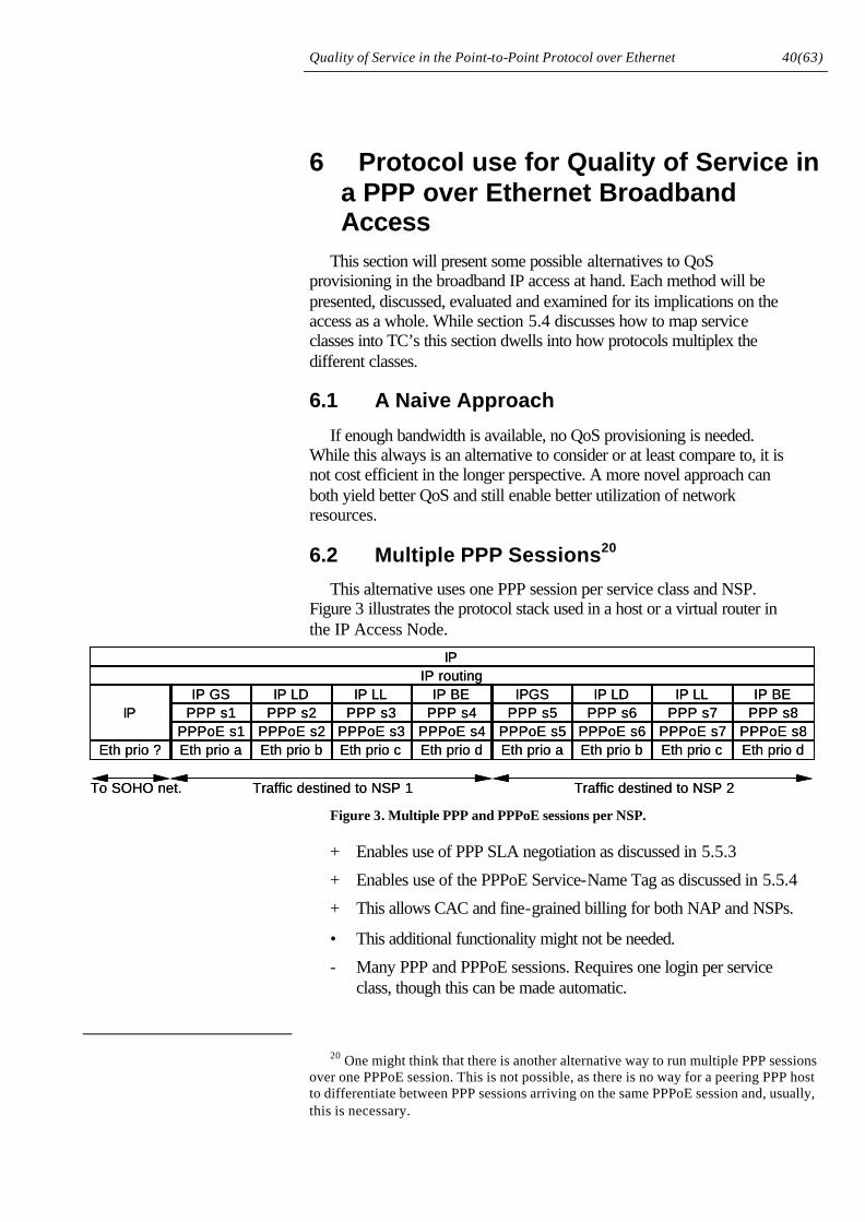
6 PROTOCOL USE FOR QUALITY OF SERVICE IN A PPP OVER ETHERNET BROADBAND ACCESS 40
6.1 A NAIVE APPROACH 40 6.2 MULTIPLE PPP SESSIONS 40 6.3 MULTIPLE PPPOE SESSIONS 41 6.4 DIRECT MAPPING - A SIMPLE APPROACH 41 6.5 PREREQUISITES, CONSIDERATIONS AND IMPLICATIONS 42
Quality of Service in the Point-to-Point Protocol over Ethernet 1(63)
1 Introduction Future multi-service networks based on the IP paradigm have been
anticipated to integrate all communication services as well as to provide new services. This envisaged network would not only provide new and extended services to its users, but also simplify and integrate the communication realm, bringing increased revenue to its operators, lower communications costs to its users and drive other positive spin-off effects.
This network is required to offer Quality of Service in a manner suitable for all services in order to efficiently aggregate traffic under all conditions and yield a cost effective network design. Another requirement is the large-scale deployment of broadband IP access allowing service consumers the use of these services.
This thesis addresses the Quality of Service issues in a specific broadband IP access based on Ethernet LAN technology and the Point-to-Point Protocol. This section presents the background and aim of this thesis and concludes with a summary of its outline.
1.1 Background
Telia are currently in the process of deploying its broadband IP-access. This access is designed according to many requirements such as those on bandwidth, cost, quality and security. Also, it is required that the customer is able to choose a Network Service Provider, NSP, upon establishing a connection.
For Telia, broadband accesses will mainly be based on ADSL and Ethernet technologies, both which are cost effective in many situations and have very high bandwidths. Quality of Service will be based on packet marking, that is the IP DiffServ model, traffic policing and traffic shaping. Security will be accomplished with Virtual LAN and login. These are all traditional and well-known technologies. The ability to choose a Network Service Provider can be a more difficult problem.
The Point-to-Point Protocol, PPP, has been used for many years in network access and facilitates Authentication, Authorization and Accounting, AAA, e.g. with widespread Remote Dial-In User Service, RADIUS, efficient IP address assignment and a possibility to choose telecom operator upon connecting. However, PPP requires a one-to-one relationship between communicating hosts while Ethernet is not a one-to-one serial link. PPP over Ethernet (PPPoE) is defined in [1] and provides a way of running PPP on Ethernet. There are similar methods for running PPP over ADSL. Hence, Telia is investigating the possibility to use PPP in its broadband accesses.
When using PPP over ADSL, Quality of Service can be provided through ATM Permanent Virtual Circuit (PVC) services, but for Ethernet with PPPoE the QoS issue remains open. PPPoE has not yet addressed
Quality of Service in the Point-to-Point Protocol over Ethernet 2(63)
QoS. The Differentiated Services model offers QoS in the IP network as a whole and Ethernet has a standard priority scheme in 802.1p [5].
In order to investigate the possibilities of introducing QoS support in PPPoE this Master’s project was started [2].
1.2 Aim
The aim is to investigate PPPoE from a Quality of Service perspective. To clarify PPPoE’s QoS properties, and to answer questions about its behaviour and performance under high traffic loads.
1.3 Report Outline
This report is divided into four main parts: The introductory sections, including sections one through four, the theoretical sections, five and six, the lab measurements, sections seven and eight, and the concluding section nine.
The introductory sections will introduce the project, its literature study and serve as a foundation for the rest of the report. It specifies the project (section 2), overviews the important PPP and PPPoE protocols (section 3), and summarizes the QoS efforts in relevant protocols and layers (section 4). Readers familiar with the respective subjects may skip these sections without missing significant parts of this thesis.
Theoretical sections move into details of the QoS abilities of the particular protocols involved in the IP access (section 5 and 6) and discusses specific QoS provisioning solutions (section 6) on a theoretical level. The lab measurements first describe the aim of the lab work and how they are carried out (section 7). Then the actual results are presented and discussed (section 8).
Finally, the concluding section summarises the main conclusions drawn from the previous analytical section and states the main implications of using PPPoE architecture in the broadband IP access found in this project.
Quality of Service in the Point-to-Point Protocol over Ethernet 3(63)
2 Problem Definition and Model This section presents the problems and the model of the problems that
are dealt with in this project. It will start with a general description of broadband accesses and move into a more detailed specification of this project.
2.1 Broadband Access
Broadband IP access is really the name of a service better described as high-speed or high bandwidth IP connectivity and can be achieved by many means. Several technologies exist for its realization and are sometimes called "last mile" or "local loop" technologies, and together with the deployed protocols, IP backbone connection and server infrastructure they form a broadband access. The broadband IP accesses discussed in this report are targeted for the Small Office/Home Office (SOHO) and regular Internet subscriber markets.
Important properties of a broadband access have been found to include:
• High bandwidth
• Multiservice aggregation
• Quality of Service provisioning
• Security services
• Operator selection
• Minimized infrastructure investments, i.e. for the Network Access Provider1 (NAP)
• Low cost of customer equipment and network operation, i.e. for the customer
• Ease of Management of both subscriber equipment and network
The main broadband technologies are briefly described below [22]:
• Cable modem. Uses the CATV coaxial cable network.
• Various Digital Subscriber Line (xDSL) technologies. Uses the existing telephone local loop.
1 A NAP is the operator and owner of the access network and is primarily concerned
with physical and link-layer aspects of it, i.e. data transport from the subscriber and the NSP. A NSP (Network Service Provider), of which an ISP (Internet Service Provider) is a special case, is concerned with “upper layer” services, such as security, DNS, application servers (email etc).
This distinction is important for the requirement of operator selection following the deregulation of telecom markets, where a NAP is not allowed an NSP monopoly for its NAP customers.
Quality of Service in the Point-to-Point Protocol over Ethernet 4(63)
• Power network. Uses the power lines.
• Satellite. Uses satellites for high speed downlinks2.
• Wireless LAN. Wireless data networking technologies are installed.
• Cellular network. Future wideband cellular networks, e.g. WCDMA.
• Ethernet. Installation of new high-grade cables or optical fiber.
Many of these technologies use existing infrastructure in order to keep infrastructure investments low. However, in doing so many of them lack some of the other properties mentioned above. It is predicted that eventually it will be necessary to install new cabling in order to provide sufficient bandwidth for the more demanding services such as digital TV over IP. Investments can be made now or at a later time, but the main technologies of interest for Telia (as mentioned in Section 1.1) is ADSL and Ethernet.
2.1.1 Asymmetric Digital Subscriber Line
ADSL, or Asymmetric Digital Subscriber Line, is called asymmetric because its uplink, from subscriber to Local Exchange (LE), has a lower bandwidth than its downlink. Depending on circumstances, such as the quality of the phone line, the distance to the LE and line interference, the uplink bandwidth should be around 2Mbps (1.5-8Mbps) and the downlink around 500kbps (16-640kbps) for most of Sweden's telephone subscribers. ADSL uses a Customer Premises Equipment (CPE) called an ATU-R (ATM Termination Unit – Remote), i.e. a modem, to connect the subscribers Customer Premises Network to a Digital Subscriber Loop Access Multiplexer, DSLAM, in the LE. ADSL uses ATM technology and normally, but not necessarily, an ATM network connects the DSLAM to the IP Access node that terminates the access network.
Termination means terminating the physical/link-layer access and connecting it to the IP (network layer) network after performing ingress control, e.g. conformance monitoring, Authentication Authorization and Accounting (AAA), and policing. The IP access node should also facilitate link-layer and/or network layer (IP) operator selection.
2.1.2 Ethernet
Ethernet does require installation of new cables but does on the other hand offer a symmetric bandwidth of 10Mbps, and even 100Mbps in the future. The new cabling is a large investment, but the customers Ethernet Network Interface Card (NIC) for 10BASE-T is very cheap. Ethernet accesses are further described in section 2.2.
Naturally, a NAP willing to offer both Ethernet and ADSL access values a solution that allow the two technologies to work in a seamless IP
2 And in the future also for uplink.
Quality of Service in the Point-to-Point Protocol over Ethernet 5(63)
access node, especially from a subscribers point of view. Protocols, methods and equipment used should facilitate this.
2.2 Model
This section defines a general model of the problem. Telia’s broadband IP-access is, as stated above, based on ADSL and Ethernet technologies. In both cases the customer’s devices are interconnected with a Customer Premises Network, CPN, normally using Ethernet. The customer could connect for example Set Top Boxes, STBs, IP Telephones, IPT, and ordinary Personal Computers, PCs, to his/her CPN. The above and the following are based on Figure 1, describing the broadband IP-access.
The access network between CPNs and the IP-access node is tree structured and either switched Ethernet or ADSL can be used in this tree. In the switched Ethernet access, the CPN is plugged into the installed Ethernet plug. Traffic from multiple CPNs is aggregated in a few levels of Ethernet switches, which are 802.1Q VLAN enabled [6]. They form a VLAN that includes the CPN and the IP access node.
In the ADSL access, the CPN plugs into the ADSL modem, which in turn connects to the phone line (bridged access [19]). Many phone lines are demodulated and multiplexed by a DSLAM connecting to the IP access node. Effectively, there is a VLAN in operation here too since ADSL uses ATM PVCs.
The IP-access node is basically a router where traffic shaping and AAA is performed. More than one access tree based on either ADSL and DSLAM or switched Ethernets can connect to the access node. Capacities in the access tree are carefully planned. VLANs ensure that customers cannot intervene with other customers’ traffic unless passing through the policing in the access node.
Quality of Service in the Point-to-Point Protocol over Ethernet 6(63)
EthernetPhysical
PPPoEPPPIP
EthernetPhysical
PPPoEPPPIP
EthernetPhysical
EthernetPhysical
EthernetPhysical
EthernetPhysical
Sw Sw
RIP
IP
Customer Equipment
Ethernet Switch
Ethernet Switch
IP-access Node
EthernetPhysical
PPPoEPPPIP
EthernetPhysical
PPPoEPPPIP
EthernetPhysical
EthernetPhysical
EthernetPhysical
EthernetPhysical
Sw Sw
RIP
IP
Customer Equipment
Ethernet Switch
Ethernet Switch
IP-access Node
Figure 1. Broadband IP-access with Ethernet and ADSL. Ethernet bandwidths are just examples.
When PPP is used, each customer equipment uses a protocol stack with IP on top of PPP on top of PPPoE on top of Ethernet3, as illustrated in Figure 2. In order to pass QoS information, i.e. DiffServ/TOS information, from the IP-layer to Ethernet’s “p-bits” [5], this information will have to pass through, and hence be supported by, PPPoE. Ethernet frames can then receive their fair share of QoS when transported to the IP-access node.
Figure 2. Protocol stacks.
3 Other stacks can also be implemented. For example the simple IP on Ethernet can
be used for intra CPN traffic (so for example printers can be shared). The host will route traffic to the appropriate stack.
ATM
STB
PC
IPT
Ethernet Sw
Ethernet Sw
Ethernet Sw
IP-accessNode
AAA
IP Network
100Mbps Ethernet
10Mbps Ethernet
1Gbps Ethernet
ADSL.
STB
PC
IPT10Mbps Ethernet
ADSL
DSL
AM
Quality of Service in the Point-to-Point Protocol over Ethernet 7(63)
The IP-access node can with the help of RADIUS and the structured username login4 determine how to handle logins and traffic from different users. A NSP can have a virtual router installed in the IP access node to terminate PPP session and relay them onto their home network through the NAPs network or its own. Alternatively, the NAP can tunnel the PPP IPCP session to the selected NSP, based on the structured username, which in turn terminate the PPP session5.
2.3 Alternatives and Motivation
This section aims at pointing out the alternatives to PPP and PPPoE, and motivates the use of it in this broadband access. It is not up to this thesis to motivate the PPP/PPPoE use but this section serves to inform the reader and raise the awareness of alternatives and the original motivation of taking this path. In fact, the PPP/PPPoE use is, as indicated in the title, given as a prerequisite.
Remote broadband IP access based on PPP/PPPoE has many advantages [2][11][16][17][22][23]:
• It allows for access control and billing in a similar manner to, and through reuse of existing proven technology, i.e. NSPs migration.
• It allows for NSP selection in existing technology and in a simple manner.
• It allows for efficient IP address assignment (1 per session). Less IP addresses are needed compared to IP sub-netting.
• Users are presented with a familiar interface when logging on and PPP software is well spread. PPPoE software is open source for Linux, and inexpensive for Win/Mac systems.
• PPP Authentication mechanisms can be used, which integrate with existing AAA technologies.
• Access control, service control and billing can be done on per-user basis rather than per physical access/subscription.
• It can facilitate a unified model for both ADSL and Ethernet accesses6.
• PPPoE is transparent to PPP, and users of PPP.
Drawbacks to the use of PPP/PPPoE include
• Overhead and connection delay (but it can be made very short, Section 8.2.1).
• It requires PPPoE to be installed, configured and supported in customer equipment.
4 The subscriber uses a username that indicates the selected NSP. E.g.
‘[email protected]’, ‘[email protected]’ or ‘[email protected]’ 5 Perhaps it also multiplexes many PPP sessions into one L2TP tunnel to the NSP. 6 As ADSL based accesses seem to favor a PPPoE solution [17] [16] [23].
Quality of Service in the Point-to-Point Protocol over Ethernet 8(63)
• Quality of Service provisioning has not been satisfactory addressed.
The last drawback is really the topic of this project [2].
Alternatives to the PPP based broadband IP access have to include facilities for AAA, and operator selection. One such alternative is to use IP Source Routing, where the chosen NSPs IP address is source routed by a host or the IP access node. Login can be made using HTTP. This simple approach has several disadvantages to PPP. For example, the host or IP access node must know IP addresses of all NSPs, and source routing is the most common IP address spoofing attack7, why it is filtered out by most firewalls.
Proxy PPP [11] lets another host (e.g. the IP access node) act as a proxy, running the host’s PPP sessions. This also allows an intact protocol stack at the customer equipment. It does, however, lack the same AAA functionality and puts additional processing in the IP access node.
Other alternatives include L2TP like solutions [7][23]. Like PPP it tunnels its way but require more overhead. L2TP uses PPP and hence its AAA functionality. IP in IP tunneling is another simple alternative. The problem of knowing the NSPs IP address appears here too, and it lacks AAA.
All these alternatives put a lot of complexity in the IP access node so as to work reasonably. None of them address the IP address problem, provides a common model for both ADSL and Ethernet accesses, or includes a per user authentication as good as PPP.
2.4 Issues
As discussed in section 1.1 and stated in 1.2, the problem concerns Quality of Service, QoS, in PPPoE.
The main issues at hand can be loosely stated as:
• With what methods can QoS support be introduced in PPPoE? This really means mapping QoS info from IP TOS/DiffServ through the protocol stack. Can the Service-Name TAG be used? What implications does these methods have?
• Can services with different QoS requirements be multiplexed over the same PPPoE session?
• PPP is a serial protocol, how does it react to packet loss, delay and reordering? What performance implications does this have?
• What issues have to be addressed in the IP-access and the PPPoE software?
7 IP address spoofing is the operation where a false IP address is used in order to
conceal a security attack or minimize the risk of tracing it.
Quality of Service in the Point-to-Point Protocol over Ethernet 9(63)
2.5 Assumptions and Scope
This project concerns only the broadband IP-access based solely on Ethernet. This project will not be concerned with the effects that different design approaches, in designing the capacity of Ethernet accesses, has on QoS.
Security and multicast considerations are outside the scope. Issues concerning the Customer Premises Networks, CPNs, are left outside the scope aswell. Though IP backbone QoS affect the network access, this project leaves out specifics of the same.
Quality of Service in the Point-to-Point Protocol over Ethernet 10(63)
3 An overview of PPP and PPPoE To provide a background to the rest of this report this section presents
the basics of the Point-to-Point Protocol (PPP) and PPP over Ethernet. It is not intended as a comprehensive description of these protocols and interested readers should turn to the referenced literature. Familiar readers may skip this section.
3.1 The Point-to-Point Protocol
The Point-to-Point Protocol [4][3][10] is a link layer protocol originally designed for dial up networking but incorporates many facilities making it a popular protocol with numerous other applications. PPP provides negotiation of link layer properties, support for multiple network layer protocols and configuration of these, and encapsulates these network layer payloads. It is symmetrical and operates over any full-duplex serial link. Though it requires a one-to-one peer relationship this does not limit PPP as for example PPP over Ethernet (PPPoE), section 3.2, can be used to set up such relationships between Ethernet hosts.
PPP is divided into two parts, specifically the Link Control Protocol (LCP) and the Network Control Protocol (NCP). The LCP is responsible for establishing, negotiating, and optionally authenticating and testing the link. It is up to the NCP to set up the network layer protocols to operate across the link and each network protocol has its own NCP to accommodate its respective needs. More than one network layer protocol can be negotiated and used simultaneously.
The PPP frame format used in HDLC-like framing is shown in Figure 3. HDLC-like framing is a common framing but, for example, PPPoE have no use for flags, HDLC addresses and FCSs and hence omits them. PPP uses byte stuffing to avoid flags (x7E) inside the frame. Address is set to the HDLC “all stations” address, xFF, and the control field indicates the use of PPP is set to x03.
Address Control HDLC PayloadFlag FCS FlagHDLC:
1 Octet
Code ID PPP Payload/OptionsProt No. LengthPPP:
Address Control HDLC PayloadFlag FCS FlagHDLC:
1 Octet
Code ID PPP Payload/OptionsProt No. LengthPPP:
Figure 3. PPP in HDLC-like framing.
Quality of Service in the Point-to-Point Protocol over Ethernet 11(63)
3.1.1 The Link Control Protocol
Once the Physical layer indicates that a connection has been established, e.g. after modem connection establishment8, PPP enters LCP. A state diagram, illustrating LCPs basic operation, is shown in Figure 4.
Figure 4. LCP basic state diagram.
In the Dead state the physical layer is not ready. When it becomes ready the transition up to Establish takes place. Here, LCP configure packets are exchanged to negotiate all options of LCP. If it succeed, an Authentication phase is entered before the NCP can commence its operation in the Network state. Once that state is finished (i.e. the network layer user has finished using the link), PPP returns to the Dead state via a Terminate state, where the link is brought down in an orderly fashion. It can also happen if LCP packets appear on the link to terminate it during the Network state. Also LCP can disrupt the Network state for renegotiations of the link, and will then, in fact, return to the Establish state.
LCP uses a frame format displayed in Figure 5.
1 Octet
Code ID PPP Payload/OptionsProt No. LengthPPP:
Length ValueType ...LCP:
1 Octet
Code ID PPP Payload/OptionsProt No. LengthPPP:
Length ValueType ...LCP:
Figure 5. LCP frame format.
The protocol number for LCP is xC021 and the code field identifies the different LCP packets. ID is used to match requests with responses to the same. The Data/options field contains TLV type options or data.
8 This could be done with for example Link Access Procedure for Modems (LAPM).
Dead
Authenticate
Establish
Network
Terminate
UPOPENED&AUTH. REQ.
OPENED &NO AUTH
FAIL
FAILSUCCESS
CLOSING
DOWN
FAIL
Quality of Service in the Point-to-Point Protocol over Ethernet 12(63)
Negotiation is a complicated procedure with a complex finite state machine. It is performed for each link direction and its basics are illustrated in Figure 6.
Figure 6. Basic LCP negotiation.
1. First a Configure-Request packet is sent with the options preferred by the sender.
2. These options can be rejected collectively (if the peer doesn’t understand them) with a Configure-Reject, or selectively with a Configure-NAK (which also contains ‘hints’ to the peer on how to change its options), or fully accepted with a Configure-ACK.
3. The sender rectifies his options according to a Configure-NAK/Reject and sends another Configure-Request.
4. Eventually the negotiation is closed with a Configure-ACK.
Naturally, LCP contains time-outs to recover from lost or erred frames. When LCP enters the Terminate state a Terminate-Request is sent and ACKed by the peer. This also involves a timer.
Other LCP packets include
• Code-Reject. An unknown code in a LCP packet was encountered, indicating a different version of PPP.
• Protocol-Reject. The PPP Protocol field was unrecognised indicating an attempt to negotiate a protocol unknown to the peer.
• Echo-Request and Echo-Reply. For LCP loopback.
• Discard-Request. Used as a sink mechanism, e.g. in debugging and performance testing.
3.1.2 The Network Control Protocol and the IP Control Protocol
When the LCP has entered the Network state, NCP packets are allowed on the link. NCPs set up network protocols on the link and negotiate these network layers’ specific options.
One particular NCP is the IP Control Protocol (IPCP), which services the set up of IP including IP address assignment. Its protocol number is x8021 and the corresponding encapsulated IP datagrams use x0021. It
1. Configure-Request
3. Configure-Request
2. Configure-NAK
4. Configure-ACK
t
Quality of Service in the Point-to-Point Protocol over Ethernet 13(63)
basically uses the same negotiation scheme as LCP, but only the Code-Reject, Configure-X and Terminate packets are used. The most important options are IP-Compression-Protocol and IP-Address and should be clear from their names.
3.2 The Point-to-Point Protocol over Ethernet (PPPoE)
The Point-to-Point Protocol over Ethernet, or PPPoE, is a lightweight method for carrying PPP sessions across a, possibly bridged, Ethernet Local Area Network (LAN). It is defined as an informational RFC [1] by vendors. This section merely overviews PPPoE from a point relevant to this master project and the reader is referred to [1] for a comprehensive description.
As PPP expects to use a serial, point-to-point, link where the only recipient of transmitted data is the other end, and as Ethernet is a medium with many recipients, a procedure is needed to set up a one-to-one relationship between the peering entities running PPP. One easy solution would be to broadcast all packets but that would consume unnecessary bandwidth and can possibly compromise security in switched Ethernets. In addition, hosts on the LAN cannot know if a link establishment frame was intended for them or not and how would two PPP sessions on the same LAN be separated.
PPPoE allows for two hosts on an Ethernet LAN to learn each other’s Medium Access Control (MAC) addresses through a discovery protocol, and then to start a transparent PPP session with a unique session ID. It is intended for use in broadband accesses where the session abstraction of PPP is desired. There are other alternatives to using PPP/PPPoE in broadband accesses as well as there are several other reasons for its usage, but these discussions are left to section 2.1 and 2.2. In broadband accesses, it is assumed that there is a, so-called, Access Concentrator (AC), which terminates the IP access and serves as the connection point with an IP backbone. It will perform necessary Authentication, Authorization, and Accounting (AAA) functions.
3.2.1 Protocol Operation
PPPoE has two stages to it, namely the Discovery stage and the PPP Session stage. The Discovery stage starts out to find the peer of this session, and thus its MAC address. Then, it will set up a unique PPPoE session identifier. It will be unique in the sense that it together with the peering Ethernet MAC addresses uniquely identifies this particular PPPoE session.
Quality of Service in the Point-to-Point Protocol over Ethernet 14(63)
Discovery is performed as a client-server message exchange, where the Access Concentrators act as servers. Messages are encapsulated in the Ethernet payload with an ETHER_TYPE set to 0x8863 during the Discovery stage and 0x8864 during PPP session stage. The PPPoE headers are shown in Figure 7.
1 Octet
TypeVersionSession ID
Length
Code
Payload (i.e. PPP/Options)
1 Octet
TypeVersionSession ID
Length
Code
Payload (i.e. PPP/Options)
Figure 7. PPPoE frame format.
A four-bit version is set to 0x1 as well as the type. The code identifies what kind of packet is sent during the Discovery stage and the session id uniquely identifies a particular PPPoE session together with the Ethernet source and destination addresses. The PPPoE payload contains PPP frames during the session stage and can contain TAGs, shown in Figure 8, during the discovery stage.
2 Octets
Tag Length
Tag Value
Tag Value
2 Octets
Tag Length
Tag Value
Tag Value
Figure 8. PPPoE Tag format.
Some Tag-types are defined further in [1] and more can be defined if they safely can be ignored by implementations not supporting them, otherwise they have to be included in a newer version of PPPoE. TAGs are used to carry information pertaining to the session being set up between the peers.
Quality of Service in the Point-to-Point Protocol over Ethernet 15(63)
3.2.2 Discovery Stage
This section describes the normal operation of the PPPoE Discovery stage, which is illustrated in Figure 9.
Figure 9. PPPoE protocol operation.
The Discovery stage starts by a host broadcasting a PPPoE Active Discovery Initiation (PADI) packet. Code is set to 0x09 and session id to 0x0000. At least one tag must be included of type Service-Name indicating the service this host is requesting.
An Access Concentrator that receivers a PADI packet can reply with a unicast (to the client) PPPoE Active Discovery Offer (PADO, code 0x07 and session id still 0x0000) packet in which it offers at least one service with the use of Service-Name tag and announces itself with a AC-Name tag.
The host can now receive many PADO packets and chooses one server. It now knows its MAC address and unicasts a PPPoE Active Discovery Request (PADR, code 0x16 and session id still 0x0000) packet back to the chosen AC. This contains one Service-Name tag specifying what service the client requests.
Now the AC can generate a unique Session-ID and insert it into a PPPoE Active Discovery Session-confirmation (PADS, code 0x65)
t
Mulitcast PADI, w Service-Name
Unicast PADR, w Service-Name
Unicast PADO, w Service-Name(s)& AC-Name
Unicast PADS, w Service-Name& Session ID
Unicast PADO, w Service-Name(s)& AC-Name *)
*) There may be multiple ACs answering with a PADO**) May be sent by either side
PPP session Stage
Unicast PADT, w Session ID **)
Quality of Service in the Point-to-Point Protocol over Ethernet 16(63)
unicast to the host. It should include one Service-Name tag specifying what service is to be carried during the following Session stage.
There are other Tags than the Service-Name and AC-Name Tags defined but they are of less interest and not described here to limit the scope of this overview.
3.2.3 PPP Session Stage
Once the Discovery stage has finished, PPP frames are encapsulated in the payload of PPPoE without HDLC framing. This means that the PPP frame starts with the PPP Protocol-ID. All packets are unicast, the Ethernet type field reads 0x8864, the PPPoE code field is 0x00, the Session-ID contains the unique session ID derived in the Discovery stage. When PPP runs on PPPoE some options are forbidden in LCP and it usually runs with error check but without retransmission.
At the point PPPoE enters the session stage it becomes state-full. PPPoE Active Discovery Terminate (PADT) packets are used for two-way termination of the PPPoE session.
Quality of Service in the Point-to-Point Protocol over Ethernet 17(63)
4 Overview of Quality of Service in the IP, PPP, PPPoE and Ethernet layers
Quality of Service (QoS) has become important with the worldwide deployment of the Internet and ambitions to carry new, possibly all, services over it besides traditional data services like email, news, web browsing and file transfer. The new services include for example enhanced and traditional telephony, personal, interactive and traditional TV and video, computer games, radio and music, and combinations of these, also known as multimedia services. These services have different requirements on how the network should treat its data. Requirements on for example delay, delay variation, and loss though Quality of a Service is really subjective to user perception. Hence, in a multi-service network, data can no longer be treated in the same best effort manner as it used to be if it is to be efficiently designed.
Class of Service (CoS) is a form of Quality of Service where different classes of traffic are treated in a way that makes it likely for the services that use the network to receive a certain Quality of Service. Whereas, Guarantee of Service (GoS) is a different approach that aims at somehow guarantee that every service receive their required QoS. Hence, CoS generally classify traffic and define treatment of it in the network, whereas GoS generally sets up connections through a network for specific flows of traffic. The latter leads to a more complicated solution with Call Admission Control9 (CAC), reservation procedures and state information in the network (scalability issues) but does on the other hand guarantee QoS. What is not so emphasized is that GoS and CoS strategies actually can cooperate and even coexist.
It is easily realized that QoS will have to be associated with a cost in some sense or another. If there is no cost (however defined) or a very low cost involved in transmitting packets with, for example, high priority across a network everyone will chose to do that. Anything else would be unrational and self-sacrificing. In this situation the network will start operating as a best-effort network since all packets have the same, high, priority. Also, QoS raises security issues such as how to protect against Theft of Service and Denial of Service (which is really a Grand Theft of Service).
This section provides an overview on how Quality of Service is approached in the different layers that are relevant in this project. It is conditioned by the use of IP DiffServ, see sections 1.1, 2 and 4.1. Therefore this section mainly deals with QoS in the CoS sense.
9 This adds complexity and can lead to under utilization of network resources, but
can yield a properly managed network.
Quality of Service in the Point-to-Point Protocol over Ethernet 18(63)
4.1 Differentiated Services in the Internet Protocol
Differentiated Services [8][9], which also goes under the acronym DiffServ, is one method developed within The Internet Engineering Task Force (IETF) to provide Quality of Service in the Internet Protocol. It uses the former Type of Service (TOS) byte in the IPv4 header or the Traffic Class octet of the IPv6 header, renaming it the Differentiated Services (DS) field, to differentiate between packets requiring different services from the network. DiffServ also specifies architecture for a Differentiated Services domain, with its components and functionality without dealing with implementation details.
The value of a DS field is called a DS codepoint, and packets having the same codepoint and crossing the same link in the same direction belong to the same Behaviour Aggregate (BA). In a DS enabled IP router, packets in the same BA will be treated collectively when forwarded, called a Per-Hop Behaviour (PHB).
The idea being that, for example, hosts can set the DS field according to their preferred treatment by the network stemming from the QoS needs of applications. The DS domain will then have to perform conditioning, and perhaps remarking of DS fields, on its boundaries according to service requirements and agreements to make sure users that comply with agreements (e.g. SLAs) receive requested service. Non-compliant traffic also has to be dealt with, e.g. by being remarked to “best effort” or “less than best effort” service.
4.1.1 The Differentiated Services Architecture
The architecture of Differentiated Services relies on the concept of a DS domain, in which each node internally treats packets belonging to a behaviour aggregate according to PHBs defined in the domain, and classifies, conditions and/or polices traffic entering, and possibly exiting, the domain at boundary nodes. This provides for a scalable approach that shares classification, conditioning and policing between many boundary nodes and avoids per-user and per-service state information in internal nodes.
On the interconnection of two autonomous domains where at least one of them employs Differentiated Service there need to be a Service Level Agreement (SLA) and a Traffic Conditioning Agreement (TCA) between them. The SLA determines how services are offered between the domains and the TCA regulates how traffic is conditioned to determine conformance with the SLA. These two agreements form the basis of how boundary nodes act on traffic entering and exiting a DS domain.
Boundary nodes may classify packets by interpreting packet headers (i.e. it can involve more than just the IP header) according to some rules. This function, a classifier, places packets onto conditioner elements for further processing.
A traffic profile is a specification on what rules to use when determining whether or not a particular packet is conforming to agreements, and can for example use a token bucket and define its
Quality of Service in the Point-to-Point Protocol over Ethernet 19(63)
parameters to do so. It can also specify multiple levels of conformance. Nonconforming packets can be treated differently by a conditioner.
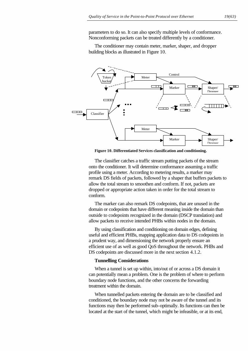
The conditioner may contain meter, marker, shaper, and dropper building blocks as illustrated in Figure 10.
Figure 10. Differentiated Services classification and conditioning.
The classifier catches a traffic stream putting packets of the stream onto the conditioner. It will determine conformance assuming a traffic profile using a meter. According to metering results, a marker may remark DS fields of packets, followed by a shaper that buffers packets to allow the total stream to smoothen and conform. If not, packets are dropped or appropriate action taken in order for the total stream to conform.
The marker can also remark DS codepoints, that are unused in the domain or codepoints that have different meaning inside the domain than outside to codepoints recognized in the domain (DSCP translation) and allow packets to receive intended PHBs within nodes in the domain.
By using classification and conditioning on domain edges, defining useful and efficient PHBs, mapping application data to DS codepoints in a prudent way, and dimensioning the network properly ensure an efficient use of as well as good QoS throughout the network. PHBs and DS codepoints are discussed more in the next section 4.1.2.
Tunnelling Considerations
When a tunnel is set up within, into/out of or across a DS domain it can potentially mean a problem. One is the problem of where to perform boundary node functions, and the other concerns the forwarding treatment within the domain.
When tunnelled packets entering the domain are to be classified and conditioned, the boundary node may not be aware of the tunnel and its functions may then be performed sub-optimally. Its functions can then be located at the start of the tunnel, which might be infeasible, or at its end,
Classifier
Marker
Meter
Shaper/Dropper
Tokenbucket
Marker
Meter
Shaper/Dropper
Control
Quality of Service in the Point-to-Point Protocol over Ethernet 20(63)
which suggests security problems (injection of traffic into the domain outside of proper boundary node conditioning).
If packets in the tunnel have different DS codepoints, they should be mapped to different PHBs in nodes along the tunnel. However, as the nodes may not be aware of the tunnels existence they cannot know how to differentiate them if the codepoints are not mapped from the IP layer internal to the tunnel to the externally visible IP layer. This can also solve the first problem. However, from a security point of view it is not satisfactory as DSCPs mappings can be intentionally false and when the tunnel terminate traffic has been injected with potentially dangerous DSCPs10.
4.1.2 The Differentiated Services Field and Per-Hop Behaviours
The DS field is illustrated in Figure 11.
1 Octet
H lengthVer Datagram lengthID
TOS/Diff ServFrag offset (13bits)Flags
TTL Protocol Header ChecksumSource Address
Destination Address
Options (if H length > 20 octets)
Data (e.g. Transport Layer Protocol)
Bit 0 2 3 5 6 7DS Code Point Unused
1 Octet
H lengthVer Datagram lengthID
TOS/Diff ServFrag offset (13bits)Flags
TTL Protocol Header ChecksumSource Address
Destination Address
Options (if H length > 20 octets)
Data (e.g. Transport Layer Protocol)
Bit 0 2 3 5 6 7DS Code Point Unused
Figure 11. Differentiated Services Field in the IPv4 datagram.
It currently only uses the first six bits of the old TOS byte. Each DS codepoint is associated with a particular PHB, and can have end-to-end, intra-domain or local significance. The all zeroes codepoint is to be mapped to the default PHB and should be the common best-effort forwarding behaviour.
Codepoints with the last three bits set to zero, are reserved as a set of eight Class Selector Codepoints, whose corresponding PHBs must satisfy special requirements. A Class Selector Codepoint having a larger numerical value than another one is said to have a higher relative order. According to [8] “The set of PHBs mapped by the eight Class Selector
10 A solution should therefore use boundary and tunnel termination SLA
enforcement.
Quality of Service in the Point-to-Point Protocol over Ethernet 21(63)
Codepoints MUST yield at least two independently forwarded classes of traffic, and PHBs selected by a Class Selector Codepoint SHOULD give packets a probability of timely forwarding that is not lower than that given to packets marked with a Class Selector Codepoint of lower relative order, under reasonable operating conditions and traffic loads”. Packets with a higher numerical value in the DS field thus receive at least equal but likely preferential treatment over packets with lower numerical DS field values.
The DiffServ approach is to define the general semantics of Per-Hop Behaviors and specify the externally observable forwarding treatment packets receive rather than the mechanisms of implementation. PHBs can be implemented using various buffer management strategies like drop preference buffer management or buffer allocation policies, and packet scheduling algorithms including Weighted Fair Queuing (WFQ), Weighted Round Robin (WRR), strict priority queuing, or variations of these. A particular PHB could be implemented with any mechanism as long as it satisfies the requirements on externally observable forwarding behavior.
Link-Layer Constraints
QoS in the Differentiated Services architecture relies on the DS field of packets and PHBs implemented in IP nodes of the network. Now nodes can be interconnected with various link-layer technologies that may not be dedicated links and may aggregate traffic, e.g. switched LAN technologies. Here, the link-layer technology can drop packets, e.g. due to overload or buffer overflow, and hence must be able to treat packets with care taken to the overlying DS architecture. The link-layer QoS abilities may be coarser than those specified in DS and the mapping to its capabilities may not be specified or clear. This may render treatment of different BAs unsupported or indistinguishable. One Link-Layer technology, namely switched Ethernet with 802.1D support, is discussed in section 4.4.
4.2 Quality of Service in the Point-to-Point Protocol
Quality of Service in PPP has mainly been focused on the problems associated with low bandwidth links such as modem links. Due to the fact that large packets occupy the link for a relatively significant amount of time when being transmitted, efforts were made to allow for fragmentation of large packets in favour of small packets containing real-time data with requirement on low end-to-end delays [20][21]. A typical calculation involves a 1500 byte packet being transmitted over a 28.8kbps modem line, thus requiring over 0.4s transmission time, which is much larger than the required end-to-end delay for real-time applications such as IP telephony.
In this case, when high bandwidth links such as Ethernet LANs are considered, fragmentation holds little gain. What is required is something similar to the DiffServ or IntServ approach. DiffServ would require packets carrying a field of QoS information and hence require additions
Quality of Service in the Point-to-Point Protocol over Ethernet 22(63)
to the PPP standard. IntServ requires state information in nodes along the way, but PPP holds state information anyway. In this case it is relevant that if DiffServ is implemented in hosts, packets will likely be transmitted in a prudent order, as DiffServ will schedule the packets as appropriate from above PPP. This automatically gives PPP a form of QoS support, but if PPP sessions are aggregated (e.g. onto L2TP tunnels [7][23]) it still lacks support if different DS BAs exist in the aggregated sessions.
4.3 Quality of Service-work on Point-to-Point Protocol over Ethernet
No major Quality of Service efforts have been made in PPP over Ethernet to date. One way would be to use the Service-Name tag (see section 3.2) to announce what QoS this session is requiring. Different services could set up different sessions altogether or one session could be set up for each CoS. This could integrate CAC mechanisms, DiffServ and/or 802.1p mappings.
Another method would be to simply pass QoS info from DiffServ as a parameter through PPPoE to Ethernet priorities. This violates the layering concept but here PPP, PPPoE and Ethernet layers together can be considered to make up the whole link layer. All these suggestions are really what this project is about so they are left for further discussion in Section 5.
4.4 Ethernet Traffic Classes
Quality of Service in Bridged/Switched11 Local Area Networks has been addressed in IEEE Std 802.1D [5][14] and IEEE Std 802.1Q [6]. The “Q” standard [6] deals with how Virtual LANs12 (VLAN) can be built on bridged/switched LANs. This includes a tagged frame format where a VLAN Identifier (VID) resides and leaves space for a priority field in each packet. This priority, also known as user_priority, originates from work on Traffic Classes in IEEE 802.1p incorporated in the “D” standard [5].
Legacy LAN technologies have had a bad history in MAC layer priority schemes. What has been used in these MAC schemes is access priority (relating to the priority in accessing the media) but the most widely used LAN technology, Ethernet, does not have any such scheme. Token Bus, Token Ring, FDDI and DQDB offer eight levels of access priority but are vaguely specified and rarely used. These two new
11 The terms bridge and switch can really be used interchangeably throughout. 12 A Virtual LAN is loosely defined as a concept where LANs separated with
bridges and/or switches can seamlessly participate in a Virtual LAN and operate as if on the same LAN. Exempli gratia, multicast frames are transmitted on all the VLAN segments and on no other LAN segments, and frames can only be forwarded to other segments in the same VLAN. The actual behavior of VLANs can be specified in filtering databases.
Quality of Service in the Point-to-Point Protocol over Ethernet 23(63)
standards unify the behaviour of bridge and switch equipment and can still be backward compatible.
LANs are often over-provisioned and can under light load deliver a high QoS. Still, under bursty traffic conditions discrimination is needed between time sensitive and non-time sensitive traffic in aggregation points such as switches. Also, when the traffic load is high the non-deterministic back-off period of CSMA/CD result in large delays (and undefined delay bounds [12]). In this case with dedicated13 switched Ethernet the access delays are nonexistent and QoS can be provided solely by the implementation of Ethernet Traffic Classes in switches.
4.4.1 Tagged Frame Format
The tagged frame format facilitates the carriage of VID14 and user priority information. It is inserted immediately after the destination and source MAC addresses15 in the frame where the Ethernet Type field starts. The tagged frame format is illustrated in Figure 12.
Destination MAC Address (6B)Source MAC Address (6B)
B – Byte/Octet
b - bit
Type (2B)
CRC (4B)
Data Payload (variable)
Destination MAC Address (6B)Source MAC Address (6B)
TPID (2B)
CRC (4B)
Data Payload (variable)
TCI (2B)
CFI802.1Q Tag Type (16b)
User prio (3b)VLAN ID (12b)
Normal Ethernet frame format
Ethernet tagged frame format
Destination MAC Address (6B)Source MAC Address (6B)
B – Byte/Octet
b - bit
Type (2B)
CRC (4B)
Data Payload (variable)
Destination MAC Address (6B)Source MAC Address (6B)
TPID (2B)
CRC (4B)
Data Payload (variable)
TCI (2B)
CFI802.1Q Tag Type (16b)
User prio (3b)VLAN ID (12b)
Normal Ethernet frame format
Ethernet tagged frame format
Figure 12. Ethernet normal and tagged frame format.
The tag starts with the Tag Protocol Identifier, TPID, presenting this as a tagged frame. It is set to the 802.1QTagType of x8100. The TPID is followed with a Tag Control Information, TCI, which carries the three bit user_priority and a bit indicating the format of routing information if used. A twelve bit VID is inserted last.
13 One station per segment (i.e. switch port) in full duplex operation 14 Virtual LAN Identifier. 15 Except when routing information (supported by some MAC protocols) is present.
The routing field exceptions are not considered in the rest of this section to limit its scope.
Quality of Service in the Point-to-Point Protocol over Ethernet 24(63)
User_priority is encoded as a unsigned integer and has thus eight levels of priority, 0-7, where 7 is the highest priority. Their use is discussed next.
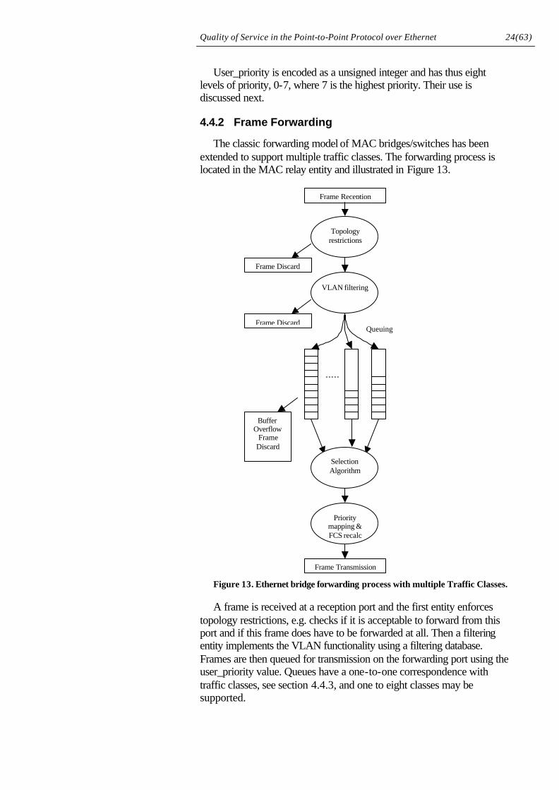
4.4.2 Frame Forwarding
The classic forwarding model of MAC bridges/switches has been extended to support multiple traffic classes. The forwarding process is located in the MAC relay entity and illustrated in Figure 13.
Figure 13. Ethernet bridge forwarding process with multiple Traffic Classes.
A frame is received at a reception port and the first entity enforces topology restrictions, e.g. checks if it is acceptable to forward from this port and if this frame does have to be forwarded at all. Then a filtering entity implements the VLAN functionality using a filtering database. Frames are then queued for transmission on the forwarding port using the user_priority value. Queues have a one-to-one correspondence with traffic classes, see section 4.4.3, and one to eight classes may be supported.
Frame Reception
Topologyrestrictions
VLAN filtering
SelectionAlgorithm
Prioritymapping &FCS recalc
Frame Transmission
Frame Discard
Frame DiscardQueuing
BufferOverflow
FrameDiscard
Quality of Service in the Point-to-Point Protocol over Ethernet 25(63)
Next, frames are selected for transmission and the forwarding device has to support strict priority queuing. It may employ other selection strategies but a frame received on the same port with the same user priority, destination and source address must not be reordered. Lastly, user priorities are mapped to access priorities, if used, on the transmission port and the Frame Check Sequences, FCS, recalculated if necessary before the frame is passed down to the MAC layer.
4.4.3 Traffic Types and Traffic Classes
802.1D [5] defines the use and interpretation of the user_priority information in a tagged frame. It identifies seven different Traffic Types and their intended use.
• 7 Network Control. E.g. management traffic to maintain and support the network.
• 6 “Voice”. Less than 10ms delay and maximum jitter through LAN infrastructure.
• 5 “Video”. Less than 100ms delay.
• 4 Controlled Load. Traffic under some form of admission control.
• 3 Excellent Effort. Important applications.
• 0 Best Effort.16
• 2 Spare17
• 1 Background. Bulk data transfers not to impede other services or “Penalty tagged” non-conforming traffic.
Names of traffic types originate from a characterizing service. The traffic type numbers correspond to user_priority values. These traffic types are then mapped into traffic classes. This mapping depends on how many traffic classes are supported by a particular switch illustrated in Table 1.
16 Best effort is the classic default traffic type in LANs and is numbered 0 for
compatibility. 17 Number 2 is arbitrarily reserved as a spare.
Quality of Service in the Point-to-Point Protocol over Ethernet 26(63)
No. Traffic Classes (No. Queues)
Traffic Types
1 1 Best Effort, (All)
2 1 Best Effort, Excellent Effort, Background 2 Voice, Controlled Load, Video, Network Control
3 1 Best Effort, Excellent Effort, Background 2 Controlled Load, Video, 3 Voice, Network Control
4 1 Background 2 Best Effort, Excellent Effort 3 Controlled Load, Video, 4 Voice, Network Control
5 1 Background 2 Best Effort, Excellent Effort 3 Controlled Load 4 Video 5 Voice, Network Control
6 1 Background 2 Best Effort 3 Excellent Effort 4 Controlled Load 5 Video 6 Voice, Network Control
7 1 Background 2 Best Effort 3 Excellent Effort 4 Controlled Load 5 Video 6 Voice 7 Network Control
8 (same as 7)
Table 1. Number of Traffic Classes mapping to Traffic types.
The standard also specifies how access priorities are to be used in conjunction with traffic types.
Quality of Service in the Point-to-Point Protocol over Ethernet 27(63)
5 Overview of Quality of Service in a PPP over Ethernet Broadband Access
This section together with the next one constitutes the theoretical part of this thesis. It will discuss the means for QoS provisioning in the protocol stack at hand and the possible use of them. Section 6 continues by presenting some concrete alternatives on how to achieve QoS, all on a theoretical level.
Subsections will discuss the use of Differentiated Service classes in the Telia IP network. A discussion regarding the mix of QoS strategies continues. QoS functionalities and responsibilities in relevant protocols are discussed before the turn comes to Ethernet Traffic Class use. Then the problem of multiplexing and demultiplexing QoS flows is addressed, before related multicast and signalling issues conclude.
5.1 Telia Differentiated Services Network
Telia’s IP network is expected to build on the Differentiated Services paradigm. Initially, four service classes presented below will be used [24]. Quality of Service in this protocol stack will always have to set out from these as they provide QoS end-to-end.
1. Guaranteed Service. A zero loss service, i.e. with deterministic bandwidth guarantees, within an established SLA much like a leased line. It will require peak rate allocation in backbone as well as access, and traffic conditioning at edges. Likely only a few destination addresses will be included in the service and specified in a rather static manner. This class can carry voice, video as well as traditional data traffic.
2. Low delay, low delay jitter. Intended for delay sensitive traffic, such as voice and video, providing a low delay and limited loss service. Statistical QoS parameters, and ingress policing.
3. Low loss. Intended for prioritised data traffic with a (significantly) lower loss than best effort. Statistical QoS parameters, and ingress policing.
4. Best Effort. The traditional service with no guarantees. It will, however, not be starved by other classes. No QoS provisioning, and no ingress policing. Other classes’ non-conformant traffic may be remarked as best effort.
There are a number of implications to the choice of these service classes of which some, regarding the use of Ethernet traffic classes in conjunction with them, are discussed in section 5.4. What DS code points will be used, if any of the defined PHBs (namely Assured Forwarding and Expedited Forwarding PHBs) will be used, and how they would be used remains to be resolved.
Quality of Service in the Point-to-Point Protocol over Ethernet 28(63)
The use of a Guaranteed service class requires prudent implementation when a low delay class is present. In order to satisfy both classes’ QoS requirements, network design must be careful.
The single low delay class can potentially mean a problem. Voice and video services are different in the sense that they generate delay sensitive traffic with different bandwidths and can in each case have real-time and non real-time requirements with strict delay bounds, thus splitting into four services:
• Real-time voice (relatively low bandwidth, low delay and delay variation), e.g. IP telephony.
• Real-time video (relatively medium to high bandwidth, low delay and delay variation), e.g. Video telephony.
• Non real-time voice/audio (relatively low to medium bandwidth, low delay variation), e.g. Voice messages, streamed audio.
• Non real-time video (relatively high bandwidth, low delay variation), e.g. Video on Demand, IP TV et cetera.
Aggregating all of them in one service class can potentially lead to problems, as this class will have to provide the strictest common denominating requirement, i.e. low delay and delay variation. But it is also a much simpler approach than splitting them into several similar classes. However, the most important distinction between the four services is the real-timeliness of them and two classes might be enough as is the case with Ethernet Traffic Classes splitting delay sensitive traffic into two classes. The bandwidth requirements are more relevant to network design, dimensioning and CAC. Another solution is to carry non real-time traffic in low loss or best effort classes and use large buffers, which is the idea behind Telia’s service classes.
An implication of DiffServ use is that hosts must have the ability to set DSCPs of their packets, i.e. requiring a mapping of application traffic or use of a QoS enabled API, and be configured to use Telia’s service classes properly. Some operating systems (e.g. including Win 9x [13]) already include these APIs for RSVP based QoS.
5.2 Heterogeneous Quality of Service
It has been anticipated [30][13][15] that QoS architectures will be mixed in future networks. Integrated Services, MPLS18, ATM, Ethernet 802.1p and Differentiated Services will have to be integrated or cooperate and efforts have been made from the start to allow it. This is relevant to this project in order to maintain a comprehensive view on QoS end-to-end provisioning. It naturally affects QoS in the broadband IP access.
18 Not a QoS architecture by means, but rather a routing protocol, though used in
conjunction with the others it can provide QoS in different ways than the others alone.
Quality of Service in the Point-to-Point Protocol over Ethernet 29(63)
What has also been predicted is where the different strategies will prevail or at least dominate each other and which one is more suited for current and future application QoS requirements. Most agree on for example DiffServ’s excellent scalability, ATM’s speed, IntServ’s ability to provide fine-grained application QoS, 802.1p’s simplicity and MPLS’s simplification of backbones. Naturally, these strategies have more features, advantages and disadvantages to each other.
It is believed that strategies highly scalable in bandwidth and aggregation of QoS flows, like DiffServ, MPLS and ATM will prevail in the high-speed backbones where QoS will still be provided even with coarse mechanisms due to the high bandwidth available (low queuing delays despite long queues) and less bursty traffic conditions19. Whereas, in the access networks, where bandwidth is scarce, the level of aggregation is less (as there are fewer sources) making traffic burstier, reservation QoS strategies with guaranteed service would be more successful. With fewer flow endpoints here, reservation scaling problems will not be as prevalent.
Ethernet is simple, cost efficient and can with dedicated switched topologies provide QoS support in the access. With Subnet Bandwidth Manager (see section 5.4.2) it can also use IntServ. ATM is the preferred transport of ADSL access technology, but QoS here can also use simple PVCs for each DiffServ class, thus bringing CoS into ATM. In the backbone MPLS can use DiffServ. Alternatively, it can use RSVP or ATM PVCs to allocate bandwidth to its label switched paths (containing aggregated flows rather than individual flows like in “normal” RSVP allowing for better scaling).
Efforts in the IETF are underway to develop the Bandwidth Broker (BB) concept [30]. A BB is used to exchange SLAs between domains in order to provide end-to-end QoS in heterogeneous QoS networks as illustrated in Figure 1. This figure also shows how domains with dissimilar QoS can cooperate for end-to-end QoS.
19 Traffic from many independent sources will approach a Gaussian traffic pattern as
the number of sources increase. Whereas, few sources, such as the situation on a LAN, will generate what is called a fractal traffic pattern, i.e. highly bursty in nature.
Quality of Service in the Point-to-Point Protocol over Ethernet 30(63)
BB
BB
BB
BB
Layer 3 deviceRouter/Host
Layer 2 deviceSwitch
BB Bandwidth Broker
VC
VLAN
- SBM
RSVP based QoS using SBM in LAN NetworkAccess
ATM based QoS in ATM /ADSL Network Access
RSVP may traverse Core Domains or just map to DiffServ.
RSVP cooperates with P-NNI orDiffServmarked traffic is mapped to PVCs.
DiffServ basedQoS in Network Core
MPLS path
BB
BB
BB
BB
Layer 3 deviceRouter/Host
Layer 2 deviceSwitch
BB Bandwidth Broker
VC
VLAN
- SBM
RSVP based QoS using SBM in LAN NetworkAccess
ATM based QoS in ATM /ADSL Network Access
RSVP may traverse Core Domains or just map to DiffServ.
RSVP cooperates with P-NNI orDiffServmarked traffic is mapped to PVCs.
DiffServ basedQoS in Network Core
MPLS path
Figure 1. Example of Heterogeneous End-to-end QoS
What is essential in this case is a simple solution that allows migration to future QoS provisioning strategies. Right now bandwidth is perhaps not scarce in the access, and services will not initially require other than simple QoS, as it will suffice to elevate some traffic from the (for some applications) futile best effort service. When technology matures, experience is gained and a more complete view of end-to-end QoS is available, the QoS provisioning in the access may adapt to a more optimal solution.
5.3 Roles and Scope of QoS in the Protocols
The different layers of the protocol stack has distinct roles in respect to the NAP’s and NSPs’ QoS provisioning due to the fact that they have different scope in the network. This is important in order to maintain an overall view of the QoS architecture end-to-end, and demonstrate what potential capabilities, limitations and contributions protocols can have.
In an IP network the IP protocol has end-to-end significance and scope. Hence, it provides QoS end-to-end and this is relevant to NAPs and all NSPs involved end-to-end. Ethernet traffic classes on the other hand are purely the NAP’s concern. In between these come PPP and PPPoE. PPPoE’s scope is limited to the Ethernet LAN so it becomes a concern of the NAP, whereas PPP may carry traffic from the subscriber all the way to its selected NSP. This is illustrated below in Figure 2.
Quality of Service in the Point-to-Point Protocol over Ethernet 31(63)
PPPoEEthernet
LCPIPCP
IP routing
Ethernet EthernetSw
To SOHO & Default
ISP
IP
PPPoEEthernet
LCP ?
IPCP
?IP
LCP?IP
LCP
IP routing
STB
PC
IPT SBM
Node NASAccessCPNIP DiffServ Network
internet
Located?
Ethernet 802.1p w/wo SBM c-oriented/c-less
PPPoE Service-Name Tag c-oriented
PPP SLA Negotiation connection oriented
IP DiffServ or IntServ connection oriented/connectionlessQoS scope:
PPPoEEthernet
LCPIPCP
IP routing
Ethernet EthernetSw
To SOHO & Default
ISP
IP
PPPoEEthernet
LCP ?
IPCP
?IP
LCP?IP
LCP
IP routing
STB
PC
IPT SBM
Node NASAccessCPNIP DiffServ Network
internet
Located?
Ethernet 802.1p w/wo SBM c-oriented/c-less
PPPoE Service-Name Tag c-oriented
PPP SLA Negotiation connection oriented
IP DiffServ or IntServ connection oriented/connectionlessQoS scope:
Figure 2. Scope of QoS and protocols.
Layering principles have to be extended in order for QoS provisioning to be discussed. QoS is of concern to the protocol stack as a whole and different layers have different QoS provisioning responsibilities. The individual layers provide services to upper layers. Specifically, they may create QoS services relevant to that layer using lower layer services and provide its collated QoS services to upper layers, along with the other non-QoS services it provides.
In TCP/IP, the application, presentation, session and transport layers of the ISO-OSI model are just two, the transport and application layers. They should for example accomplish: an easily used interface to QoS in general qualitative terms, transparent QoS (for example provide timeliness) for sessions, e.g. a phone call, hide the network layer’s QoS flaws, for example by buffering streamed audio/video, and maintain connections, if needed.
IP layer QoS extends all across the network as it provides the internetworking functions and forwarding. It should therefore bring together various link layer QoS functionalities and provide timely forwarding between these links. What also comes into IP’s responsibilities is the interworking of different QoS strategies. Exempli gratia, DS field definitions and use may differ from one NSP to another. Another example is when IntServ is used in one domain and DiffServ in another.
Link layers, may it be Ethernet, ATM, SDH, SONET, or PPP, need to provide QoS across their sub-network. In some cases this will not be hard work if IP does its job well (e.g. point-to-point links), in other cases link level aggregation (i.e. use of switches) makes things difficult.
In this case, the link layer as seen by IP is PPP but the real link layer is Ethernet. In normal point-to-point links, bandwidth is dedicated and as stated above PPP does not have to worry about QoS. PPPoE is an adaptation of Ethernet to PPP. Ethernet itself can provide class based
Quality of Service in the Point-to-Point Protocol over Ethernet 32(63)
QoS in cooperation with DiffServ, though these layers cannot communicate directly.
As seen in Figure 2, above, it seems as PPPoE holds little use in QoS provisioning as it has the same scope as Ethernet, which contain the ultimate means of providing QoS (see 5.5.4). If PPP is terminated in a virtual router at the IP access node, it also serves little purpose (see 5.5.3).
5.4 Use of Ethernet Traffic Classes
This section discusses the use of Ethernet Traffic Classes described in Section 4.4. More specifically, it deals with the problem of mapping between Telia’s four Differentiated Services service classes and Ethernet traffic classes. It should be clear that the ultimate means of providing QoS in this access network is by using 802.1p user priorities to allow packet discrimination in Ethernet switches along the path to the access node.
As mentioned in the previous section, the differences in delay requirements of delay sensitive services may not be satisfied by one low delay service class, but perhaps with two as with Ethernet Traffic Classes, TC.
The choice of DS to TC mapping largely depends on buffer allocation policies and packet scheduling algorithms. What complicates this matter is the fact that the Ethernet standard uses strict priority scheduling, though other algorithms may be used. Strict priority means problems to support a guaranteed service along with a low delay service. However, with proper network design this problem can be solved.
The ideal solution would be to use highly configurable queuing algorithms and buffer allocation policies, adapted to the SLAs present on the switched LAN at hand, similar to the DiffServ approach. For example, consider a situation where traffic is aggregated onto a certain port of a switch under the following conditions. The guaranteed service class traffic is known to be 10% of the port’s capacity (according to SLAs) and marked with higher priority than other traffic classes. The next highest traffic class marking is held by the low delay service class, followed by the low loss class. The low loss class is anticipated to be highly bursty and constitute a maximum of 40% of average port capacity. Whereas the low delay class is smoother, and likely to demand 30% of the capacity.
In this case, there is no problem to support the different service classes, but to do it well is. Strict priority will solve the problem, but might increase delays for the low delay class with non-compliant traffic from the guaranteed class (i.e. exceeding the agreed traffic volume, here 10%). Careless buffer allocation might increase the loss of the low loss class, when it is pre-empted by the higher classes. Large bursts in the higher classes can then significantly starve the best effort traffic.
A better approach is to use WFQ and allocate 10% of the bandwidth to the guaranteed service and perhaps 75% of the capacity to low delay
Quality of Service in the Point-to-Point Protocol over Ethernet 33(63)
and low loss traffic, so these will not starve best effort. Then, allocate a reasonable buffer capacity to the guaranteed service class considering its burstiness and SLA. A, likely, smaller buffer for low delay class considering how long delay these packets can take before becoming useless. The low loss buffer can be huge, as well as the best effort buffer, to make maximum use of multiplexing gain under bursty conditions.
The choice of Ethernet traffic classes for DiffServ service classes can be done in several ways.
1. Use static table to map from DS to TC.
+ Simple.
+ A good first solution.
+ Adaptable to future change while still inexpensive.
• How is the mapping done? Simple problem but solution must consider future changes.
- Static.
- Requires configuration in hosts.
- Harder to dimension network.
2. Let hosts recommend what TC to use for each packet. Use CSCP (first three bits of CP) for selecting DS class 1 to 4, and the remaining three bits in CP to specify the preferred Ethernet Traffic Class (which also is three bits).
+ Can provide good QoS.
+ Flexible, new classes are added easily.
• It is still not decided how CPs are used in Telia DiffServ network.
- Requires extra (non-standard) functionality in hosts.
- Non-standard use of CP. More complexity required when traffic is passing into other operator’s DS domains.
3. Use a Subnet Bandwidth Manager and Integrated Services.
+ Good QoS support.
+ IntServ in access network can become the future way of things.
+ Standardized.
• Should scale reasonable within the access.
- Complexity, e.g. reservation schemes.
- Introduces setup delays.
- Requires extra functionality and CAC.
- Requires use of RSVP, or similar, in hosts.
- Most expensive approach, while still risky.
- Requires special software in hosts.
Quality of Service in the Point-to-Point Protocol over Ethernet 34(63)
Some vendors may have their own use of the 802.1p user_priority. However, vendor specific, non-standard QoS efforts are not suitable due to interoperability problems (subscribers most likely to use equipment and software from a large set of vendors) and in order to avoid depending on any specific vendor.
Clearly, the number of queues or traffic classes supported by each switch should be the maximum, i.e. eight, to allow for future modifications, while they could be configured to use only four.
An implication of using Ethernet traffic classes is that the MTU size is decreased by two bytes to 1498 bytes, for Ethernet encapsulation, and 1490 for LLC/SNAP encapsulation.
5.4.1 Static Mapping
The mapping between DSCPs and 802.1p user priorities can be done in several ways. It is clear, however, that some rules must hold.
• The mapping should be able to satisfy QoS requirements under anticipated traffic loads (well-designed network) in an efficient manner while using strict priority queuing.
• Future additions to the service model must be considered.
• Use of other queue scheduling algorithms should be taken into account.
Clearly, to facilitate correct QoS with strict priority queuing the service classes have to be ordered as:
1. Guaranteed Service
2. Low Delay Service
3. Low Loss Service
4. Best Effort
Some realistic mappings are discussed next.
Ethernet Traffic Class Service Class
7 Network Control Guaranteed Service
6 Voice Low Delay (-jitter)
5 Video
4 Controlled Load Low Loss
3 Excellent Effort
0 Best Effort Best Effort
1 Background
Table 2. Ethernet traffic class to service class mapping
+ Low delay, loss and BE traffic uses recommended traffic classes
- Mixes Guaranteed Service with Network Control
Quality of Service in the Point-to-Point Protocol over Ethernet 35(63)
- Hard to police/shape GS traffic in switches (need to look at MAC addresses too).
Ethernet Traffic Class Service Class
7 Network Control
6 Voice Guaranteed Service
5 Video Low Delay (-jitter)
4 Controlled Load Low Loss
3 Excellent Effort
0 Best Effort Best Effort
1 Background
Table 3 Ethernet traffic class to service class mapping
+ NC traffic is separated.
+ Easier to police/shape GS traffic in switches.
- GS and LD classes do not follow recommendations.
Ethernet Traffic Class Service Class
7 Network Control
6 Voice Low Delay (-jitter)
5 Video
4 Controlled Load Guaranteed Service
3 Excellent Effort Low Loss
0 Best Effort Best Effort
1 Background
Table 4 Ethernet traffic class to service class mapping
+ Follows recommendations.
+ NC traffic is separated.
- Will not work with strict priority.
- Compliant low delay traffic in GS class will receive worse QoS than LD class traffic.
Quality of Service in the Point-to-Point Protocol over Ethernet 36(63)
Ethernet Traffic Class Service Class
7 Network Control
6 Voice Guaranteed Service, Low Delay (-jitter)
5 Video
4 Controlled Load Low Loss
3 Excellent Effort
0 Best Effort Best Effort
1 Background
Table 5 Ethernet traffic class to service class mapping
+ NC traffic is separated.
+ Follows recommendations reasonably
- GS and LD classes mixed
Following is a discussion and some foreseen implications.
Clearly, GS and NC traffic can be reasonably predicted and are easier to design for. Luckily, that means that their affect on other classes can be predicted.
Algorithms other than strict priority need to be investigated. What algorithms are being implemented in switches and how do these effect switch performance? How should they be used for optimal use of network resources and QoS provisioning? These are issues for future work.
The mapping could be implemented easily in PPPoE software, which passes packets down to Ethernet software. A simple check in the packet reveals the DSCP, a table lookup yields the Ethernet traffic class to be used and the packet is passed to the Ethernet driver with correct type and VLAN tag. The first switch maps frames into their correct VLAN’s, it can also filter out packets attempting a service not subscribed, and also map untagged frames.
5.4.2 Subnet Bandwidth Manager and Integrated Services
The Integrated Services over Specific Link Layers (ISSLL) work group of The Internet Engineering Task Force have identified the problem of providing bandwidth guarantees in LANs and standardized an IntServ based QoS that uses a Subnet Bandwidth Manager (SBM) [18][26][27][28]. A SBM will maintain the per flow state information similar to what RSVP enabled routers do, perform CAC on the RSVP requests in the LAN, and recommend Ethernet traffic classes to be used with the admitted flows. This can be done in a centralized and a decentralized manner, of which the former uses a centralized function per managed domain (collection of LAN segments) whereas the latter requires SBM implementations in switches.
Quality of Service in the Point-to-Point Protocol over Ethernet 37(63)
SBM is not expected to receive wide deployment in broadband IP access networks. It requires more investments, depends on RSVP and IntServ market acceptance and its finer grained QoS will, at least initially, not be needed. It also inherits scalability problems from RSVP, though they might not be as apparent in an access network. However, it holds a significant advantage in the fact that Windows APIs implement RSVP. SBM might be a future development into a better, more fine-tuned, QoS provisioning.
5.5 Multiplexing of different QoS classes
One problem faced in this project is how to differentiate between flows in the protocols. One application/host may have multiple QoS requirements, thus utilizing multiple QoS flows. Multiple QoS flows may in turn have to use one protocol/connection/session (e.g. PPP session or PPPoE session).
A solution will require the mapping of QoS information between layers and utilize different means of QoS in these. Some of those facilities are presented in subsections below.
5.5.1 IP DS field
The IP DiffServ field forms the base of QoS classes as it is a prerequisite and also because it constitutes the mean for end-to-end QoS provisioning. It is what distinguishes the QoS flows.
5.5.2 IP routing
IP routing can be used to demultiplex packets with different QoS requirements into different protocol stacks or protocol sessions running on the host. This routing can be based on source and destination IP addresses, DS field values, and upper layer protocol fields (e.g. TCP/UDP port numbers) et cetera. Using upper layer protocol headers, flows requiring QoS provisioning can be filtered out and replace QoS API needs at least temporarily.
The destination IP address, supplied by the NSP, can be used to route traffic through the correct PPP session to that NSP. This is apparently supported in Win98/2000 [23] though earlier versions set up a default route to the last PPP session to be setup. DS field values can further refine routing to different stacks provisioning different traffic classes.
There is a risk that NSPs’ IP subnets clash in the subscriber’s host. For example, a user connects to a VPN service using the 10.0.0. subnet, and then connects to another NSP providing IP telephony, which in turn happens to use the same subnet for that service. This can be avoided by proper Network Address Translation, NAT, in the IP access node and coordination between NSPs.
Quality of Service in the Point-to-Point Protocol over Ethernet 38(63)
5.5.3 PPP Differentiated Services SLA Negotiation
An Internet draft [25] proposes extensions of PPP’s IPCP to support negotiation of Service Level Agreement upon session establishment. The negotiation is based on use of DiffServ.
The basic idea is that the PPP session initiator can ask its peer to provide a certain Quality of Service for this session’s traffic and specify the traffic profile. The peer then rejects, partly rejects or fully accepts the request and includes a DSCP to be used, in a negotiation scheme just like in IPCP. PPP sessions can be rejected if a user has not subscribed to a specific service with its NSP and provide error information.
Though still an Internet draft it provides a mean for subscribers to dynamically request QoS provisioning from a NSP. It could also let NSPs implement CAC. Perhaps this is a good idea or perhaps service will, at least initially, be specified in permanent SLAs. One disadvantage is that every service class requires a different PPP session, resulting in many sessions to the same NSP. Similar functions can be performed with PPPoE’s Service-Name Tag.
5.5.4 PPPoE Service-Name Tag
PPPoE’s Service-Name Tag can be used to agree on a DS service class or Ethernet traffic class to be associated, and hence used, with the PPPoE session being established between a host and an AC. Alternatively, SBM/RSVP messages can be included in an extended Service-Name Tag. Usage of the Service-Name Tag can be defined for a broadband access and then requested by hosts in PADI packets and/or announced by access concentrators in PADO packets. PPPoE sessions can be used to reject a user that has not subscribed to a specific service.
Possibly, one PPP session could use many PPPoE sessions. The use would be when one PPP session is established per NSP and carry different (DS) service classes. PPPoE sessions then associate with Ethernet traffic classes. However, this requires PPP frames on multiple PPPoE sessions to be aggregated back into one PPP session once in the AC. This can be done using multi-link PPP, where each PPPoE session acts as one link.
Each PPPoE session can only carry one PPP session so a single PPPoE session cannot be used by all PPP sessions between a host and an Access Concentrator, as the individual PPP sessions cannot be distinguished. This method can in part or as a whole be replaced by PPP SLA negotiation.
5.6 Signalling, Multicast and QoS
Multicast capabilities are not optional but required in future IP networks, and so will QoS support of multicast. Some QoS architectures have left this for future studies while others inherently support it.
In a broadband IP access such as this one, multicast is not a concern in the access. This is due to the fact that every subscriber shares a VLAN
Quality of Service in the Point-to-Point Protocol over Ethernet 39(63)
with the IP access node and no IP layer devices are present in the access between the end hosts and the access node. Multicast can be done using Layer 2 multicast with VLAN enabled switches (optimising the link usage) but that issue is left outside the scope here. However, QoS mechanisms that are used in the access need consider the QoS mechanisms used outside the access for end-to-end QoS and hence QoS multicast.
Differentiated services are connectionless and does not limit or impede normal multicast operation. Reservation strategies, however, need to address multicast issues, as they are connection oriented and usually use a fixed path through the network with reserved resources. RSVP still has some unresolved issues.
Signalling in IP networks include Routing, Network Management, IGMP, ARP/RARP, DNS lookup, and TCP connection messages along with the inherent signalling content of TCP, IP messages etc. User signalling should in general be treated as best effort traffic in order to thwart Denial of Service attacks, whereas network signalling, not initiated by the user and essential to the network’s well-being should receive the absolute highest level of service. Less time critical large messages (like routing information transfers) could use low loss classes in order to avoid loading the network too much unless they are essential to fast routing convergence.
Quality of Service in the Point-to-Point Protocol over Ethernet 40(63)
6 Protocol use for Quality of Service in a PPP over Ethernet Broadband Access
This section will present some possible alternatives to QoS provisioning in the broadband IP access at hand. Each method will be presented, discussed, evaluated and examined for its implications on the access as a whole. While section 5.4 discusses how to map service classes into TC’s this section dwells into how protocols multiplex the different classes.
6.1 A Naive Approach
If enough bandwidth is available, no QoS provisioning is needed. While this always is an alternative to consider or at least compare to, it is not cost efficient in the longer perspective. A more novel approach can both yield better QoS and still enable better utilization of network resources.
6.2 Multiple PPP Sessions20
This alternative uses one PPP session per service class and NSP. Figure 3 illustrates the protocol stack used in a host or a virtual router in the IP Access Node.
PPPoE s1Eth prio a
PPP s1IP GS
IP routing
PPPoE s2Eth prio b
PPP s2IP LD
PPPoE s3Eth prio c
PPP s3IP LL
PPPoE s4Eth prio d
PPP s4IP BE
PPPoE s5Eth prio a
PPP s5IPGS
PPPoE s6Eth prio b
PPP s6IP LD
PPPoE s7Eth prio c
PPP s7IP LL
PPPoE s8Eth prio d
PPP s8IP BE
Eth prio ?
IP
IP
To SOHO net. Traffic destined to NSP 1 Traffic destined to NSP 2
PPPoE s1Eth prio a
PPP s1IP GS
IP routing
PPPoE s2Eth prio b
PPP s2IP LD
PPPoE s3Eth prio c
PPP s3IP LL
PPPoE s4Eth prio d
PPP s4IP BE
PPPoE s5Eth prio a
PPP s5IPGS
PPPoE s6Eth prio b
PPP s6IP LD
PPPoE s7Eth prio c
PPP s7IP LL
PPPoE s8Eth prio d
PPP s8IP BE
Eth prio ?
IP
IP
To SOHO net. Traffic destined to NSP 1 Traffic destined to NSP 2 Figure 3. Multiple PPP and PPPoE sessions per NSP.
+ Enables use of PPP SLA negotiation as discussed in 5.5.3
+ Enables use of the PPPoE Service-Name Tag as discussed in 5.5.4
+ This allows CAC and fine-grained billing for both NAP and NSPs.
• This additional functionality might not be needed.
- Many PPP and PPPoE sessions. Requires one login per service class, though this can be made automatic.
20 One might think that there is another alternative way to run multiple PPP sessions
over one PPPoE session. This is not possible, as there is no way for a peering PPP host to differentiate between PPP sessions arriving on the same PPPoE session and, usually, this is necessary.
Quality of Service in the Point-to-Point Protocol over Ethernet 41(63)
- Creates more overheads on connection establishment.
6.3 Multiple PPPoE Sessions
Here, a single PPP session is opened per NSP, and one PPPoE session per service class. PPP Multi link protocol [29] could for example be used to put packets into the correct PPPoE session according to DiffServ labels.
PPPoE s1Eth prio a
PPP s1IP GS
IP routing
PPPoE s2Eth prio b
IP LD
PPPoE s3Eth prio c
IP LL
PPPoE s4Eth prio d
IP BE
PPPoE s5Eth prio a
PPP s2IPGS
PPPoE s6Eth prio b
IP LD
PPPoE s7Eth prio c
IP LL
PPPoE s8Eth prio d
IP BE
Eth prio ?
IP
IP
To SOHO net. Traffic destined to NSP 1 Traffic destined to NSP 2
mapping!
Figure 4. Multiple PPPoE sessions per NSP.
+ PPPoE Service-Name Tag can be used.
+ Can have CAC for NAP.
- Many PPPoE sessions contributing little.
- Creates more overheads (though less than the previous alternative)
PPP SLA negotiation can actually be used here to request the Guaranteed Service class on the transfer from NAP to NSP.
6.4 Direct Mapping – A Simple Approach
This approach uses one PPP session and one PPPoE session per NSP. DiffServ codepoints are detected in the IP packet either by Ethernet software or PPPoE software before using the Ethernet interface and mapped into the correct traffic classes.
PPPoE s1Eth prio a
PPP s1IP GS
IP routing
Eth prio b
IP LD
Eth prio c
IP LL
Eth prio d
IP BE
PPPoE s2Eth prio a
PPP s2IPGS
Eth prio b
IP LD
Eth prio c
IP LL
Eth prio d
IP BE
Eth prio ?
IP
IP
To SOHO net. Traffic destined to NSP 1 Traffic destined to NSP 2
mapping!
PPPoE s1Eth prio a
PPP s1IP GS
IP routing
Eth prio b
IP LD
Eth prio c
IP LL
Eth prio d
IP BE
PPPoE s2Eth prio a
PPP s2IPGS
Eth prio b
IP LD
Eth prio c
IP LL
Eth prio d
IP BE
Eth prio ?
IP
IP
To SOHO net. Traffic destined to NSP 1 Traffic destined to NSP 2
mapping!
Figure 5. A single PPP and PPPoE session per NSP.
+ Very simple
- Very simple, does not allow dynamic negotiation of QoS or CAC.
Quality of Service in the Point-to-Point Protocol over Ethernet 42(63)
6.5 Prerequisites, Considerations and Implications
All methods naturally require Ethernet NICs to be able to set 802.1p user priorities and software to request them set. This should not present significant problems as discussed in section 5.4. They also require hosts to be able to mark packets with DSCPs, use a QoS API capable of such operation or RSVP/SBM signaling.
All strategies presented here rely on the use of 802.1p/D compliant switches with dedicated full duplex ports. Non-compliant switch is better than hub since it decreases access delay (due to CSMA/CD), and utilizes aggregation more efficiently.
QoS in the Customer Premises Network have deliberately been left outside of the scope here. Mainly, because it is not the concern of a NAP, and also it largely depends on QoS provisioning in the access network, as customer resources generally are limited. CPNs are generally over-provisioned, best effort traffic usually uses TCP or RTP/RTCP, which use congestion avoidance mechanisms such as slow start and rate adaptation. However, problems can arise in larger hubbed LANs when MAC delays are significant.
Security and management aspects have not been addressed to limit the scope.
Quality of Service in the Point-to-Point Protocol over Ethernet 43
7 Lab measurements This section will describe the aim of the lab measurements and how
they were carried out, while the next section focuses on the results.
7.1 Aim
The aim of the laboratory part in this thesis project was to investigate the stability of the PPPoE architecture when used in a QoS enabled network and what implications that has on the broadband access as a whole. It is not to be a protocol validation, but rather a study of real protocol implementations.
This has been interpreted to include studies of protocol behaviour when packet loss, delay, duplication and reordering are present and the performance relative to “normal” IP on Ethernet architecture, IPoE. This is because PPP is a serial protocol and duplication and reordering are not common in serial links, also PPPoE implementations have not been extensively tested. The additional overhead and specific workings of the PPP and PPPoE protocols might also have implications on performance, which should be quantified.
7.2 Potential Vulnerabilities
Some protocols have vulnerabilities inherit in them, while they include means of forfeiting other potential problems. However actual implementations might not use these means and can also use behaviours that avoid vulnerabilities in the protocol. By not being compliant with the protocol standard an implementation can also cause interoperability problems, affect performance, and create new vulnerabilities. This is what makes a study of implementations harder than a protocol validation.
Below is a list of potential vulnerabilities in the PPPoE architecture, when packet loss, delay, duplication, and reordering, are present, derived from analysing the protocol specifications.
• Timers not set and reset properly, or used carelessly can lead to weaknesses or performance degradation.
• Packet loss can result in race conditions, dead locks or live locks. This however seems unlikely considering the fact that packet losses also occur on serial links.
• Packet sequence or identification numbers may drive protocols into undesired states when packet reordering or duplication is not considered. Such identification numbers are present for example in PPPoE: Host-Unique Tag, AC-Cookie, LCP and IPCP: ID number.
• Performance can be adversely affected by additional packet overhead, packet size constraints and fragmentation, extra
Quality of Service in the Point-to-Point Protocol over Ethernet 44(63)
processing overhead, connection delays, and undesired link layer operation.
Some of these vulnerabilities are easily avoided if implementations comply with protocol standards and by cautious and prudent implementation choices, while others are of more serious concern.
7.3 Tools and Equipment
The tools and equipment used in the measurements are briefly described below. Section 7.4 describes how they are used
Tools:
• Packet delayer. Delayer v1.0. This program was developed as a part of this project. It uses a host computer with two NICs and in default operation it forwards all traffic between the two. It can then be configured to drop or delay all or every nth packets matching certain criteria.
• Traffic generator. Ngen v1.0 was used to load the network during performance studies. Traffic was transmitted on one Ethernet port of a host machine and received on the other in order to monitor packet losses and arrival rates etc.
• Traffic monitor. GNU Ethereal21 v0.8.3 was used to monitor traffic during the stability study and hence determine abnormal protocol behaviours.
• Traffic monitor along with small tools. Tcpdump22 v3.4 was used with some tools developed in the project to plot traffic data rates during the performance study. The tools extract timestamps and packet sizes out of tcpdump data and sums up the total data rate for each second, so a throughput versus time graph can be plotted.
Equipment:
• PPPoE Client. Client computers used EnterNet 300 on a Windows98 or 2000 platform.
• VLAN Switches. 3Com Super Stack II Switch 1100, with 10/100Mbps FD/HD ports
• Network Hubs.
• Monitor station. A Red Hat Linux 6.1 host with two Ethernet NICs and monitor tools installed.
• Delayer and Load generator station. A Red Hat Linux 6.2 host with two Ethernet NICs, Ngen and the packet delayer installed.
• IP access node. Unisphere ERX-700 Edge Router.
21 Using libpcap v0.4, libz 1.1.3, and UCD SNMP 4.0.1 22 Using libpcap v0.4
Quality of Service in the Point-to-Point Protocol over Ethernet 45(63)
• FTP server. Red Hat Linux 6.0 running Washington University FTP Server, v2.4.2.
• Line modem. 1Mbps HD Home PNA Line modem from Tut Systems.
7.4 Setup
The lab measurements have been divided into two studies of which the first one uses the packet delayer to study stability and the second one studies performance. The two studies use different setups each illustrated below in Figure 6 and Figure 7.
Client
Traffic Monitor
Packet DelayerHub Hub
Access Concentrator Client
Traffic Monitor
Packet DelayerHub Hub
Access Concentrator
Figure 6. Lab setup for protocol stability studies.
Client
Traffic Monitor
Sw. Sw.
Access Concentrator
Traffic Monitor
Bottleneck link: 10Mbps FD –1Mbps line modem
Traffic load
Test traffic
FTP Server Client
Traffic Monitor
Sw. Sw.
Access Concentrator
Traffic Monitor
Bottleneck link: 10Mbps FD –1Mbps line modem
Traffic load
Test traffic
FTP Server
Figure 7. Lab setup for performance studies.
7.5 Measurements
The measurements are divided into two innate parts, one focusing on stability and the other on performance. How these are to be performed is detailed below.
7.5.1 Stability
A packet delayer is to be used to study the stability of PPP/PPPoE by simulating conditions with packet loss, delay, reorder, and duplication. The test can be divided into two main parts:
Quality of Service in the Point-to-Point Protocol over Ethernet 46(63)
1. Connection Setup a PPPoE Active Discovery b LCP Negotiation c PAP Authentication d IPCP Negotiation
2. Session & Connection Termination
In the Connection Setup each protocol’s operation is studied separately as they are independently and sequentially performed (upon completion of the first one the next takes over)23. For each protocol each setup packet type and identification number (or equivalent if applicable) was studied by:
• Dropping all or some of its type and id.
• Delaying all or some of its type and id. Delays are determined by studying timeouts and general timing in protocol operation.
• Reordering its type or id with respect to other packets of same or different type and/or id.
• Duplicating all or some of its type and id.
Naturally all discrete values of delay and all combinations of drop, delay and reordering the different packets could not be tested within the scope of this project. The approach taken has focused more on testing above-mentioned vulnerabilities and eliminating the possibility that more elaborate and unlikely combinations can cause harm.
The Session and Connection Termination was studied in the same fashion with an exception in the former. Being that IP packets were considered so every n:th packet with the clients IP destination and later source address were affected by the delayer.
7.5.2 Performance
The performance study will focus on determining the maximum throughput in PPP/PPPoE and normal IPoE and compare these, and also include measuring and evaluating the connection establishment delay.
The latter will be measured simply by repeating connection establishments and average the time it takes. Evaluation will be based on the stability study and timing relations in the Connection setup phase and suggest some improvements.
As all applications use the IP payload it becomes the common reference and hence the throughput will be defined as bits of useful IP payload transferred per second. Throughput measurements will be done in a few test cases:
• 10Mbps Full Duplex
23 This is not entirely true because LCP and IPCP can renegotiate links after the
initial setup has been done. This is not relevant here even though it has consequences when packets are duplicated or severely delayed as will be shown later.
Quality of Service in the Point-to-Point Protocol over Ethernet 47(63)
• 1Mbps Half Duplex Bottleneck (10Mbps link choked with a line modem)
• 10Mbps Full Duplex under 9Mbps traffic load
• 10Mbps Full Duplex under 9Mbps traffic load using VLAN to separate traffic.
TCP traffic will be used to accomplish this as TCP adapts to the network conditions and strives to achieve equilibrium at highest possible throughput. Also it will be interesting to see how it competes for resources with a traffic load that does not back off (like UDP). The traffic generator can monitor its loss and arrival rate and an FTP application (uses TCP) was used as test traffic.
All test cases are performed with small round trip delay as the focus was on maximum throughput studying PPPoE and TCP limitations should therefore be avoided.
The test scenarios were chosen for the following reasons:
• To see how an unloaded network compares to a loaded network.
• To compare a choked (lower bit rate half duplex) link24 to an unrestricted link and make sure PPP/PPPoE scaled well in that respect.
• To compare a choked link’s throughput to a loaded network with the same available bandwidth to test traffic.
• To see how Virtual LAN’s will affect the throughput under heavy traffic load and if it affects PPPoE, as VLANs will be used in the IP access.
Traffic measurements will be plotted as throughput versus time, where throughput is averaged over one second. This avoids packet scale variations in the traffic, i.e. every packet will of course arrive at 10Mbps though only the average throughput is of interest, while still catching larger scale variations in the traffic.
The stable equilibrium parts of the traffic trace will then be used to determine the maximum average (long-term) throughput under the circumstances of the test scenario.
24 Making sure this link is the one with the strictest throughput constraint.
Quality of Service in the Point-to-Point Protocol over Ethernet 48(63)
8 Results Herein the results of the laboratory work are presented. The focus lies
in presenting abnormalities and deviations from expected behaviour of the protocols found in the stability study, and in presenting the results of the performance study. The former study is presented first.
8.1 Stability
First a typical setup will show how a connection is established in the normal case without any interference. The results pertaining to respective protocol of the connection setup process are presented next before the results of the session and termination part.
8.1.1 Typical setup operation
Before proceeding into the analysis and discussing abnormalities it is useful to present a normal successful setup scenario. A characteristic exchange of packets during the connection setup is illustrated in Figure 8
There are always two 3 second timeouts during the setup process though the packet exchange may differ slightly from time to time.
Quality of Service in the Point-to-Point Protocol over Ethernet 49(63)
PAP = Password Authentication Protocol option present in LCP Packet
ID = Identification number, a hex value or value represented by capital letter (and incremental number)
MRU = Maximum receive unit option present with value.
Magic = Magic number option present and value represented by a captial letter
IP = IP address option present in IPCP packet, null or represented by symbol: GW = default gateway, i.e. the AC’s IP address, or A the client’s assigned IP address.
1DNS = Primary DNS address option present, null or B, i.e. the client’s assigned DNS
2DNS = Secondary DNS address option present
… = Other less relevant options are present
Figure 8. Normal PPP/PPPoE connection establishment.
Quality of Service in the Point-to-Point Protocol over Ethernet 50(63)
8.1.2 PPPoE Active Discovery
PPPoE active discovery was found to be very stable due to its stateless and simple operation. Timeouts are on the side of the client and set to about three second. If a packet is dropped or its reply is dropped, or if the roundtrip delay is longer than that, the client will time out and retransmit its packet. However, one problem was encountered nonetheless.
The AC only replies with a session ID to the first PADR it receives and after that it will instead include the AC-System-Error tag with “No Resources” string value. The consequence is of course that if the first PADS gets dropped the user will eventually have to cancel and restart the connect procedure. However, the idea behind this behaviour is to thwart Denial of Service attacks aiming to exhaust the Session IDs.
Other than that, PPPoE active discovery can recover from loss, delay, reorder and ignores or copes with duplicated packets.
8.1.3 LCP negotiation
Packet drop does not cause problems for LCP, it merely times out after three seconds and the negotiation restarts. The only problem that may occur has to do with the Echo Request/Replies.
The client sends an Echo Request every 30 seconds, with an incremented ID each time. After sending two Echo Requests without a reply within 30 seconds of the last one the client assumes the link to have been terminated25 without sending a Terminate Request or PADT. AC will send an Echo Request if it has not received one in 56 seconds and try two more times every 30 seconds before terminating the connection with a Terminate Request and PADT three seconds later.
Though very unlikely, this could lead to a situation when the user cannot connect to the AC as the AC will ignore the client’s attempts to setup a new session until the initial session has been terminated26.
Generally, LCP copes with most delay, duplication, and reordering scenarios. Single packets can be delayed as much as three seconds without causing any harm.
However, LCP renegotiations can be started off with duplicated packets, where the duplicate arrives delayed until negotiation has completed, as LCP seems not to ignore used up IDs in network protocol state. All packet types can be sensitive to duplicates. However if not many consecutive packets are duplicated such renegotiations succeed and the link is brought up again.
25 This will happen a total of 90 seconds after the last successful echo. Regardless of
if there is traffic successfully being transported in the session while this happens. 26 This will take approximately another two minutes.
Quality of Service in the Point-to-Point Protocol over Ethernet 51(63)
8.1.4 PAP
The AC will wait four seconds after the LCP negotiation has completed for a PAP Authentication Request. Hence, if two Authentication Request packets (Client to AC) are dropped, the connection will be terminated (the Client waits three seconds to retransmit leaving time for only two tries). Also, the AC will only reply to the first Authentication Request it receives27, thus if the Authentication Ack is dropped or delayed more than three seconds the client retransmits the request and the connection will eventually be closed, as the client will not proceed into IPCP without a proper Ack.
The AC ignores duplicate requests as it only answers the first request.
8.1.5 IPCP negotiation
IPCP is like LCP very resilient to packet drops. If a packet is dropped the whole negotiation procedure will restart in three seconds. No abnormal behaviour or race conditions have been observed from packet drops.
Generally, IPCP copes with most delay, duplication, and reordering scenarios. Single packets can be delayed as much as three seconds without causing any harm. However, it has the same problem as LCP with duplicated packets, except duplicate Reject and Nak packets, which are ignored.
8.1.6 Session
When the PPPoE session and then the PPP connection establishment have completed drop, delay, duplication and reordering of packets is entirely up to upper layer protocols and is of no concern to PPPoE or PPP. The only difference in operation is the additional encapsulation processing and overhead of six bytes from PPPoE and two bytes from PPP.
This should result in a link maximum transmission unit of 1492Bytes and a TCP maximum segment size of 1452B without IP header options. Still TCP on the client announces it to 1414B, which is sub optimal.
8.1.7 Session Termination
If, as illustrated by the LCP Echo problem above, one peer believes the PPP/PPPoE link to be up and the other does not, it will take the client 1-1.5 minutes to realize that (during which the impatient user probably reconnects) and the AC 2-2.5 minutes to do the same. During that time no new session can be established.
A termination is of LCP’s and PPPoE’s concern, IPCP is not involved. Both a PADT and a LCP Termination Request needs to be lost in order for the peer to maintain the perception that the link is still up, as one or
27 Presumably to prevent DoS and password guessing attacks.
Quality of Service in the Point-to-Point Protocol over Ethernet 52(63)
the other packet is enough for the peer to realize it is not. Another way for it to occur is when one peer crashes.
8.2 Performance
8.2.1 Connection establishment delay
The normal connection establishment is really very similar from time to time as explained in 8.1.1, and should therefore take about the same time. The real difference in connection establishment delay from one time to another is based on the time to do PAP authentication. The connection establishment delay was measured to about 7.2s, with a 350ms standard deviation in the measurement.
Compared to the setup delay of a telephone call, this delay is magnitudes larger. Considering that, it could be useful to suggest improvements to minimize the delay. PPPoE connection is really fast leaving little room and use for improvements. LCP and IPCP on the other hand time out during the negotiations. Considering that the time out is three seconds there is definitely room for improvements here.
Possible improvements are:
• Allow simultaneous connection establishment in both directions at the same time in LCP and IPCP. This avoids IPCP Terminate Acks and ignored LCP Configuration Requests that forces client to time out before trying again. There are a total of six (3+3) seconds or 83% to save here.
• Improve response time of the PAP authentication. This might not be possible.
• Make reasonable guesses in parameters during LCP and IPCP negotiations. This means for example a Guessing IP address, default Gateway and DNS server addresses are the same as last time. Resulting in perhaps an amendment from the AC, rather than a full Reject. Though potentially reducing the number of packets exchanged the time saved in doing so is not significant.
8.2.2 Comparison to normal TCP/IP stack
It was found that IPoE advertised a window size of 17520Bytes, a maximum segment size of 1460B and agreed on window scale and selective acknowledgement options. PPPoE’s window size was 16968B, its MSS 1414B, window scale and SACK were also agreed. IP fragmentation is avoided.
With a window size of 16968B it takes much longer than the round trip time to exhaust the window.). So TCP will not be limited by its window size but by congestion and “slow start”.
Hence, the throughput should really only differ by the extra overhead in PPPoE. The PPPoE throughput should be approximately 0.63% less
Quality of Service in the Point-to-Point Protocol over Ethernet 53(63)
than IPoE with the above mentioned segment size due to packet overhead.
The maximum theoretical throughput on long delay links is strongly dependant on the window size. As TCP announces a smaller window on connection over PPPoE performance will be worse than IPoE for that simple reason. However, the difference in window size is not that large. Also, the window size can be amended by TCP if necessary during data transfer.
Table 6 summarizes the measured IP data throughputs28. Then the following figures plotting IP data throughput versus time illustrates how the traffic is behaving during the tests.
Quality of Service in the Point-to-Point Protocol over Ethernet 57(63)
Throughput on a Heavily Loaded Network with Virtual LAN separation
Figure 15. Throughput of PPPoE under 9Mbps load separated with VLAN on 10Mbps FD link.
Figure 16. Throughput of IPoE under 9Mbps load separated by VLAN on 10Mbps FD link.
0
500
1000
1500
2000
2500
3000
3500
4000
4500
5000
1 5 9 13 17 21 25 29 33 37 41 45 49 53 57
Time [s]
Th
rou
gh
pu
t [k
bp
s]
Serie1
0
1000
2000
3000
4000
5000
6000
1 5 9 13 17 21 25 29 33 37 41 45 49 53 57
Time [s]
Th
rou
gh
pu
t [k
bp
s]
Serie1
Quality of Service in the Point-to-Point Protocol over Ethernet 58(63)
Clearly there is a form of overhead related to PPPoE use other than the packet overhead. Perhaps encapsulation processing burdens the router but would it not get worse at higher bit rates. The worst case compared to IPoE is the half duplex bottleneck link, which perhaps can be explained by higher loss rates, affecting smaller packets slightly more than larger. It is clear to see in Figure 11, “Throughput of PPPoE on 1Mbps Bottleneck.”, that the traffic suffers dramatic drops even in the larger scale.
It is worth noting that instead of being totally pushed away by the non back off traffic load, leaving only 1Mbps left of bandwidth, the VLAN switches implement some kind of fairness scheme and share the overloaded link’s capacity between the two streams. The load traffic receives as much loss as the test traffic if it pushes more than its share through. Preliminary, the traffic generator reported a received rate around 4.8Mbps for all 9Mbps load tests, the rest was dropped.
Quality of Service in the Point-to-Point Protocol over Ethernet 59(63)
9 Conclusions The theoretical work in this thesis has come to the following
conclusions:
• Switches in the access are to be fully 802.1p compliant and have at least eight traffic classes. Their packet scheduling algorithms are recommended to include more than strict priority scheduling, for example WFQ, and include buffer management policies, all configurable. Additionally, they should be able to employ some fairness strategy when leafs of the access tree overload the uplink toward the access node.
• Awaiting QoS APIs, IP DS field values have to be set statically according to what application is transmitting the traffic, by the hosts protocol stack
• It is recommended that one PPPoE session is established for each NSP upon connection. That all service classes are carried on the same PPP and PPPoE session to that NSP. The PPPoE implementation requests Ethernet 802.1p user priorities from the NIC according to static mappings from the IP DS field value of the packet at hand.
• Static mapping between IP DSCPs and Ethernet traffic classes are recommended, at least as a first step toward QoS enabling the access. Proposals on how these mappings can be done have been made.
• Generally, it should be noted that heterogeneous QoS strategies are likely to be used throughout the Internet and NSPs and NAPs may have to change QoS strategies in the access according to future demand and development.
• QoS for signalling should be investigated further.
In relation to the laboratory work, the following conclusions were drawn:
• PADSs and PAP Authentication Ack could be placed in a low loss traffic class to avoid problems presented in 8.1.2 and 8.1.4.
• The same strategy should not be used for LCP Echo Request/Replies as that increases the vulnerability to DoS attacks. Also, this problem will probably not arise often.
• Perhaps a PADT with the last known session ID could be sent before a new PADI is sent upon session establishment to ensure that the AC is not still in session state (8.1.3).
• LCP and IPCP should keep track of timed out and/or used IDs during a session and ignore packets using them to ensure stability (8.1.3, 8.1.5).
Quality of Service in the Point-to-Point Protocol over Ethernet 60(63)
• A large-scale study of PPPoE performance using many clients could be useful as well as further studies to what makes PPPoE perform worse than expected compared to IP (8.2.2).
• Allow simultaneous connection establishment in both directions at the same time in LCP and IPCP as discussed in 8.2.1.
Conclusively, the PPPoE architecture has been found able to incorporate QoS with no modifications to the involved protocols needed. This requires 802.1p compliant switches and NICs, and an implementation of PPPoE able to set 802.1p priorities, and will probably have to be investigated further. Sessions with different QoS requirements can be multiplexed over the access in several ways, where the simplest approach is recommended.
Further, PPP and PPPoE have been found to be stable in a QoS enabled network environment. However, some improvements are reasonable. Its performance has proven good enough, though some issues remain open and are recommended for further study.
Quality of Service in the Point-to-Point Protocol over Ethernet 61(63)
10 References [1] Mamakos, L. Et al. Feb. 1999. A Method for Transmitting PPP
over Ethernet (PPPoE). The Internet Engineering Task Force. Informational Request for Comments 2516.
[2] Johansson, Fredrik. Apr. 2000. Beskrivning av examensarbete - QoS i PPPoE. Telia Research AB, Stockholm.
[3] Black, Uyless D. 2000. PPP and L2TP: Remote Access Communications. Upper Saddle River, New Jersey, USA. Prentice-Hall, Inc. ISBN 0-13-022462-6.
[4] Simpson, W. (Editor). July 1994. The Point-to-Point Protocol (PPP). The Internet Engineering Task Force. Request for Comments 1661.
[5] Jeffree, Tony (Editor). Dec. 1998. Information technology – Telecommunications and information exchange between systems – Local and metropolitan area networks – Common specifications – Part 3: Media Access Control (MAC) Bridges. LAN MAN Standards Committee of the IEEE Computer Society. Standard: ISO/IEC 1502-3: 1998 ANSI/IEEE Std 802.1D, 1998 Ed. (Revised and redesignation of ISO/IEC 10038: 1993 [ANSI/IEEE Std 802.1D, 1993 Ed.] incorporating IEEE supplements P802.1p, 802.1j-1996, 802.6k-1992, 802.11c-1998, and P802.12e).
[6] Jeffree, Tony (Coordinating Editor). Mar. 1999. IEEE Standards for Local and Metropolitan Area Networks: Virtual Bridged Local Area Networks. LAN MAN Standards Committee of the IEEE Computer Society. Standard: IEEE Std. 802.1Q-1998.
[7] Townsley, W. Et al. Aug. 1999. Layer Two Tunneling Protocol “L2TP”. The Internet Engineering Task Force. Request for Comments 2661.
[8] Nichols, K. Et al. Dec 1998. Definition of the Differentiated Service Field (DS Field) in the IPv4 and IPv6 Headers. The Internet Engineering Task Force. Request for Comments 2474.
[9] Blake, S. Et al. Dec. 1998. An Architecture for Differentiated Services. The Internet Engineering Task Force. Informational Request for Comments 2475.
[10] Metz, C. July-Aug. 1999. A Pointed Look at the Point-to-Point Protocol. IEEE Internet Computing. Vol. 3. No. 4. pp. 85-88.
[11] Cohen, R. Oct. 1999. Service Provisioning in an ATM-over-ADSL Access Network. IEEE Communications Magazine. Vol. 37. No. 10. pp. 82-87.
[12] Pandey, A. and Alnuweiri H.M. 1999. Quality of Service support over switched Ethernet. 1999 IEEE Pacific Rim Conference on
Quality of Service in the Point-to-Point Protocol over Ethernet 62(63)
Communications, Computers and Signal Processing (PACRIM 1999), Conference Proceedings. Piscataway NJ, USA. Pp. 353-356.
[13] Seaman, M. And Klessig, B. Feb. 1999. Going the distance with Quality of Service. Data Communications International. Vol. 28. No. 2. Pp. 117-120.
[14] Jeffree, T. 1999. Unifying Class of Service provision in LANs – The role of MAC Bridges. IEE Colloquium on Services Over the Internet – What Does Quality Cost?. London, UK. Pp. 1/1-6.
[15] Keepence, B. 1999. Quality Of Service for Voice over IP. IEE Colloquium on Services Over the Internet – What Does Quality Cost?. London, UK. Pp. 4/1-4.
[16] Musiol, T. July 1999. Breitbandzugang mit PPP-over-Ethernet und xDSL. NTZ, Informationstechnik und Telekommunikation. Vol. 52. No. 7. Pp. 60-62.
[17] Komisarczuk, P. 1999. IP Access Service Provision for Broadband Customers. IEE Colloquium on Services Over the Internet – What Does Quality Cost?. London, UK. Pp. 5/1-4.
[18] Seaman, M. Et al. Dec. 1999. Integrated Services Mappings on IEEE 802 Networks. The Internet Engineering Task Force. Internet Draft, draft-ietf-issll-is802-svc-mapping-04.txt.
[19] Heinanen, J. July 1993. Multiprotocol Encapsulation over ATM Adaptation Layer 5. The Internet Engineering Task Force, Request for Comments 1483.
[20] Bormann, C. Sept. 1999. PPP in a Real-time Oriented HDLC-like Framing. The Internet Engineering Task Force. Request for Comments 2687.
[21] Borman, C. Sept. 1999. The Multi-Class Extension to Multi-Link PPP. The Internet Engineering Task Force. Request for Comments 2686.
[22] Westman, R. Oct. 1999. Den sista kilometern. Nätverk & Kommunikation. No. 17. 1999. Pp. 20-28.
[23] Ginsburg, D. 1999. Implementing ADSL. Reading Massachusetts, USA. Addison Wesley Longman, Inc. ISBN0-201-65760-0.
[24] Person, S. Mar 2000. RFQ 2.1 IP Access PA 17. Telia Research AB. Technical Report.
[25] De Clercq, J. Mar 2000. PPP Diffserv SLA Negotiation. The Internet Engineering Task Force. Internet draft <draft-declercq-ppp-ds-sla-negotiation-00.txt>.
[26] Yavatkar, R. May 2000. SBM (Subnet Bandwidth Manager): A Protocol for RSVP-based Admission Control over IEEE 802-style networks. The Internet Engineering Task Force. Request for Comments 2814.
Quality of Service in the Point-to-Point Protocol over Ethernet 63(63)
[27] Seaman, M. May 2000. Integrated Service Mappings on IEEE 802 Networks. The Internet Engineering Task Force. Request for Comments 2815.
[28] Ghanwani, A. May 2000. A Framework for Integrated Services Over Shared and Switched IEEE 802 LAN Technologies. The Internet Engineering Task Force. Request for Comments 2816.
[29] Sklower, K. Aug 1996. The PPP Multilink Protocol (MP). The Internet Engineering Task Force. Request for Comments 1990.
[30] QoS Forum, Jul 1999, QoS protocols & architectures. QoS Forum, White Paper, ‘http://www.qosforum.com/white-papers/qosprot_v3.pdf’, Last visit 6th of July 2000.