CO2 Rail Car BodyA. Open Blank and Save As Rail Body.Step 1. If necessary, open your Blank file.
Step 2. Click Save As (Ctrl-Shift-S) on the Quick AccessToolbar QAT.
Step 3. Key-in Rail Body for file name and press ENTER.
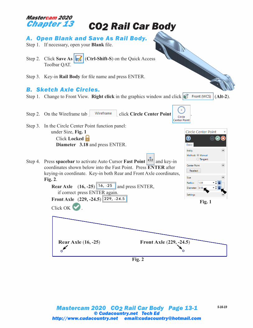
B. Sketch Axle Circles.Step 1. Change to Front View. Right click in the graphics window and click (Alt-2).
Step 2. On the Wireframe tab click Circle Center Point .
Step 3. In the Circle Center Point function panel: under Size, Fig. 1 Click Locked Diameter 3.18 and press ENTER.
Step 4. Press spacebar to activate Auto Cursor Fast Point and key-in coordinates shown below into the Fast Point. Press ENTER after keying-in coordinate. Key-in both Rear and Front Axle coordinates, Fig. 2. Rear Axle (16, -25) and press ENTER, if correct press ENTER again. Front Axle (229, -24.5)
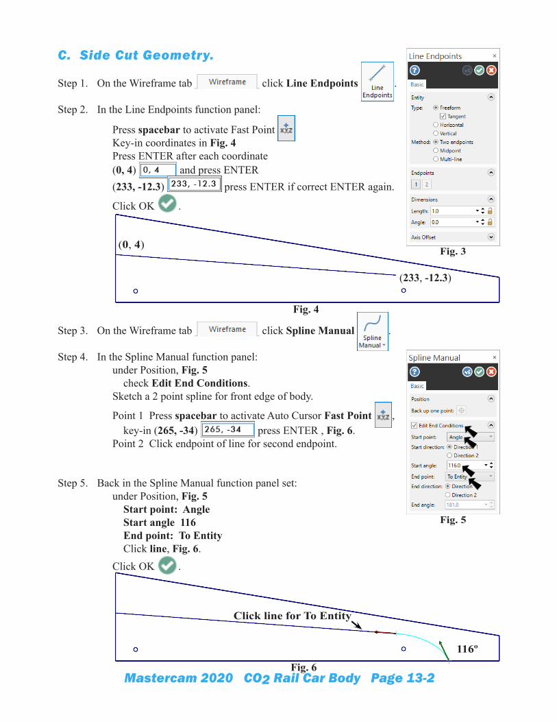
Step 1. On the Wireframe tab click Line Endpoints .
Step 2. In the Line Endpoints function panel:
Press spacebar to activate Fast Point Key-in coordinates in Fig. 4 Press ENTER after each coordinate (0, 4) and press ENTER (233, -12.3) press ENTER if correct ENTER again.
Click OK .
Step 3. On the Wireframe tab click Spline Manual .
Step 4. In the Spline Manual function panel: under Position, Fig. 5 check Edit End Conditions. Sketch a 2 point spline for front edge of body.
Point 1 Press spacebar to activate Auto Cursor Fast Point , key-in (265, -34) press ENTER , Fig. 6. Point 2 Click endpoint of line for second endpoint.
Step 5. Back in the Spline Manual function panel set: under Position, Fig. 5 Start point: Angle Start angle 116 End point: To Entity Click line, Fig. 6. Click OK .
Fig. 5
Fig. 6
116º
Fig. 4
(0, 4)
(233, -12.3)
Fig. 3
Click line for To Entity
Mastercam 2020 CO2 Rail Car Body Page 13-3
Step 6. On the Wireframe tab click Trim to Entities .
Step 7. In the Trim to Entities function panel: under Method, Fig. 7 use default Auto Trim top of rear vertical line to spline, Fig. 8. Trim right end to bottom line to spline, Fig. 9. Click OK .
Step 8. Save (Ctrl-S).
Fig. 7
Fig. 8
Fig. 9
Fig. 10
Trim
Trim
Could delete
but don’t have too
Mastercam 2020 CO2 Rail Car Body Page 13-4
D. Change Solid Color.Step 1. In the Levels Manager (Alt-Z), Fig. 11.
Show Solids level. To show, click to place a X in Visible column of Solids level.
Step 2. If necessary, toggle Translucency on (Ctrl-T).
Step 3. Click the solid body to select it, Fig. 12.
Step 4. Right click in the graphics window and on the Mini Toolbar click Solid Color drop down arrow, then click More Colors, Fig. 13.
Step 5. In the Color dialog box key-in 63 in the Current color input box and click OK ,Fig. 14.
Fig. 14
Fig. 12
Fig. 13
Fig. 15
Click solid body
Fig. 11
Mastercam 2020 CO2 Rail Car Body Page 13-5
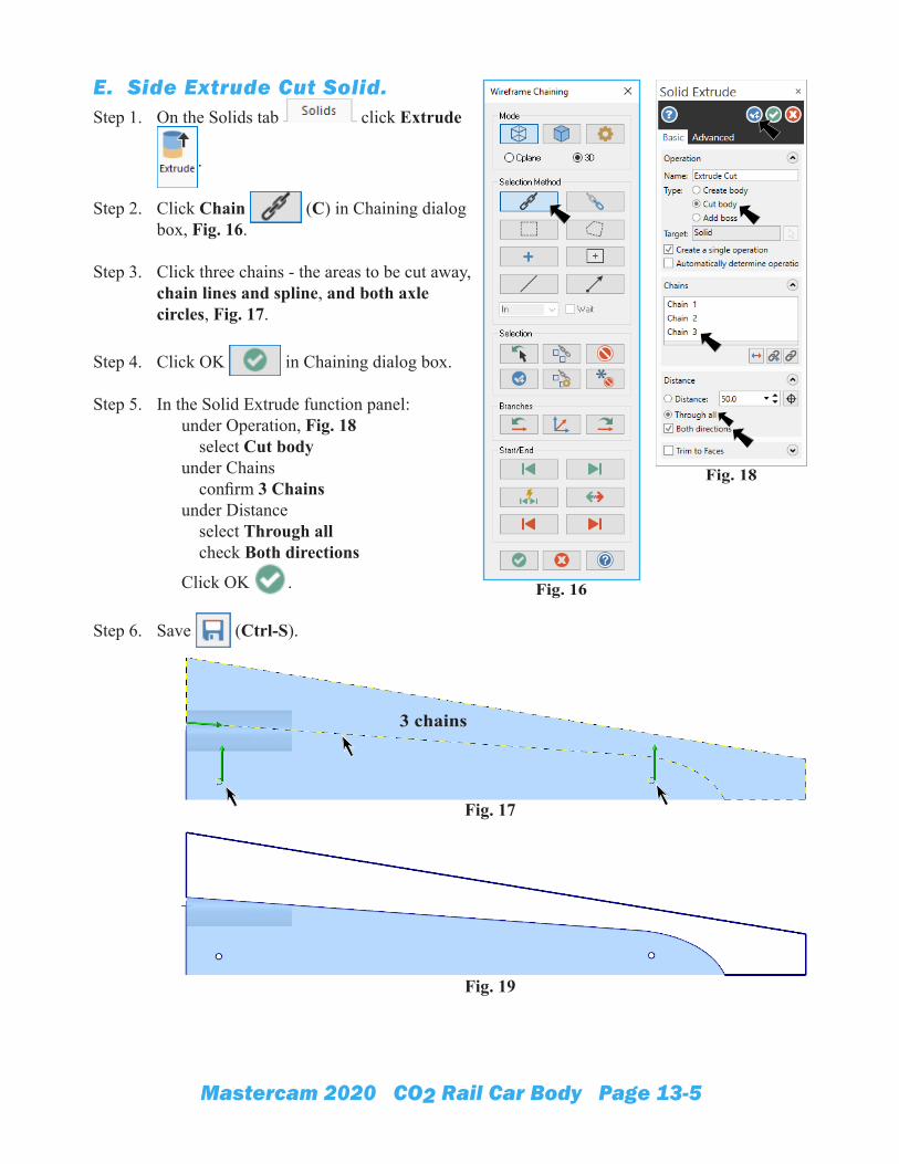
E. Side Extrude Cut Solid.Step 1. On the Solids tab click Extrude
Step 3. Click three chains - the areas to be cut away, chain lines and spline, and both axle circles, Fig. 17.
Step 4. Click OK in Chaining dialog box.
Step 5. In the Solid Extrude function panel: under Operation, Fig. 18 select Cut body under Chains confirm 3 Chains under Distance select Through all check Both directions
Click OK .
Step 6. Save (Ctrl-S).
Fig. 18
Fig. 16
Fig. 19
Fig. 17
3 chains
Mastercam 2020 CO2 Rail Car Body Page 13-6
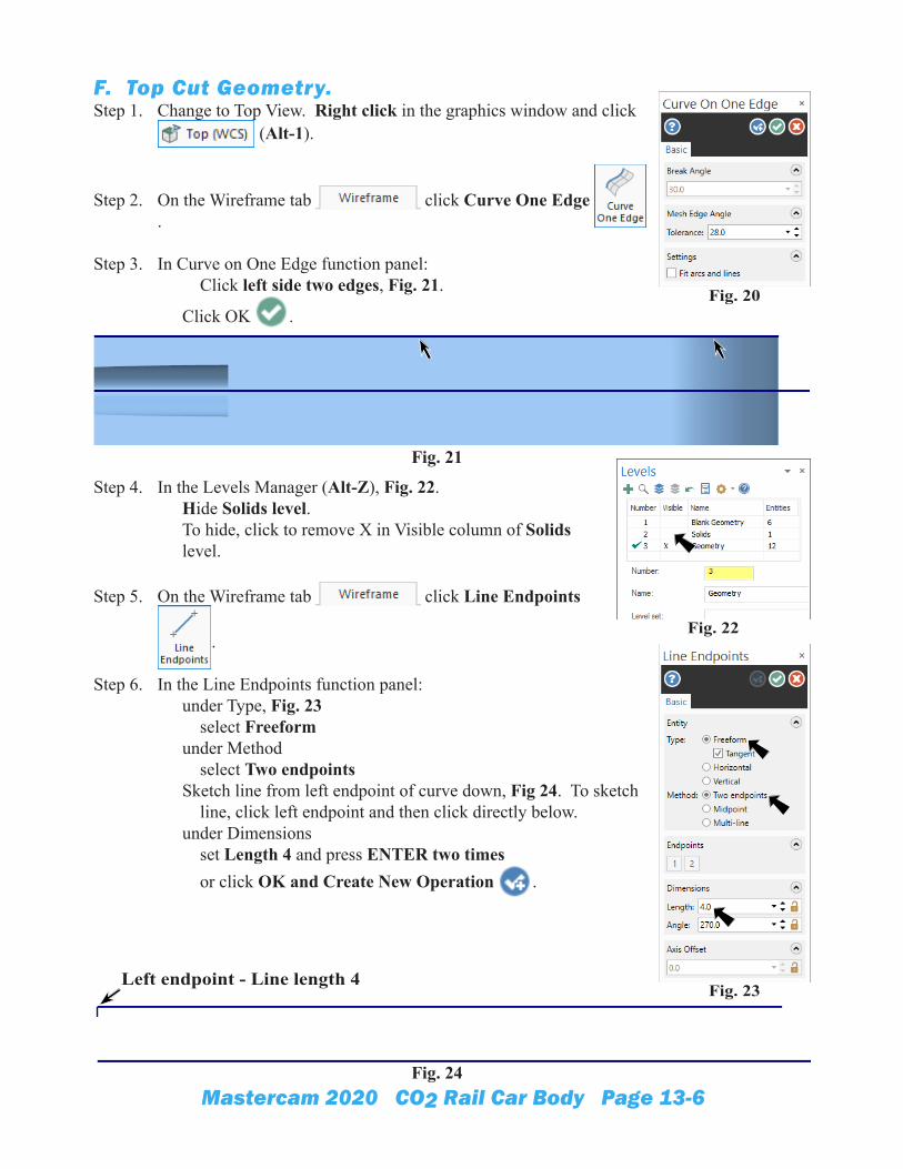
F. Top Cut Geometry.Step 1. Change to Top View. Right click in the graphics window and click
(Alt-1).
Step 2. On the Wireframe tab click Curve One Edge .
Step 3. In Curve on One Edge function panel: Click left side two edges, Fig. 21.
Click OK .
Step 4. In the Levels Manager (Alt-Z), Fig. 22. Hide Solids level. To hide, click to remove X in Visible column of Solids level.
Step 5. On the Wireframe tab click Line Endpoints
.
Step 6. In the Line Endpoints function panel: under Type, Fig. 23 select Freeform under Method select Two endpoints Sketch line from left endpoint of curve down, Fig 24. To sketch line, click left endpoint and then click directly below. under Dimensions set Length 4 and press ENTER two times or click OK and Create New Operation .
Fig. 20
Fig. 22
Fig. 21
Fig. 23
Fig. 24
Left endpoint - Line length 4
Mastercam 2020 CO2 Rail Car Body Page 13-7
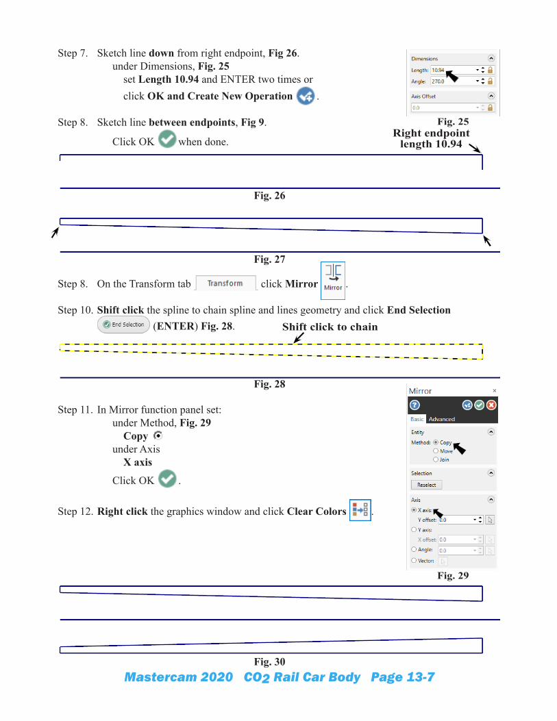
Step 7. Sketch line down from right endpoint, Fig 26. under Dimensions, Fig. 25 set Length 10.94 and ENTER two times or click OK and Create New Operation .
Step 8. Sketch line between endpoints, Fig 9.
Click OK when done.
Step 8. On the Transform tab click Mirror .
Step 10. Shift click the spline to chain spline and lines geometry and click End Selection (ENTER) Fig. 28.
Step 11. In Mirror function panel set: under Method, Fig. 29 Copy under Axis X axis
Click OK .
Step 12. Right click the graphics window and click Clear Colors .
Fig. 26
Right endpoint length 10.94
Fig. 25
Fig. 27
Fig. 29
Fig. 28
Shift click to chain
Fig. 30
Mastercam 2020 CO2 Rail Car Body Page 13-8
G. Top Extrude Cut Solid.Step 1. In the Levels Manager (Alt-Z), Fig. 31.
Show Solids level. To show, click to place a X in Visible column of Solids level.
Step 2. On the Solids tab click Extrude .
Step 3. Click Chain (C) in Chaining dialog box.
Step 4. Click the original geometry and mirror, Fig. 32.
Step 5. Click OK in Chaining dialog box.
Step 6. In the Solid Extrude function panel: under Operation, Fig. 33 select Cut body under Chains confirm 2 Chains under Distance select Through all check Both directions
Click OK .
Step 7. Save (Ctrl-S).
Fig. 34
Fig. 31
Fig. 32
Fig. 33
Chain 1
Chain 2
Mastercam 2020 CO2 Rail Car Body Page 13-9
H. Sketch Cockpit Guide Curve 1.Step 1. Right click in the graphics window and from the menu click GView > Left (WCS).
Step 2. In the Levels Manager (Alt-Z), Fig. 35. Add new Cockpit Geometry level, make active and hide Geometry level. To add level, key-in 4 in Number field and Cockpit Geometry in Name field. Click 4 in Number column to make Cockpit Geometry level active . To hide Geometry level, click to remove X in Visible column of Geometry level.
Step 3. On the Wireframe tab click Circle Center
Point .
Step 4. In the Circle Center Point function panel: under Size, Fig. 36 Diameter 30 and press ENTER. Press O key on keyboard to select Auto Cursor Origin override.
Click OK .
Step 5. On the Wireframe tab
click Trim to Entities .
Step 6. In the Trim to Entities function panel: under Method, Fig. 38 use default Auto Trim top of circle to top edge, Fig. 39. Trim circle to other edge, Fig. 40. Click OK .
Fig. 36
Fig. 35
Fig. 37
Fig. 40Fig. 38 Fig. 39
Click top of circle first
Mastercam 2020 CO2 Rail Car Body Page 13-10
Step 7. On the Wireframe tab click Line Endpoints
.
Step 8. In the Line Endpoints function panel: Sketch a line across endpoints of arc, Fig. 41.
Click OK .
Step 9. Use Ctrl-T to toggle Translucency off.
I. Create Cockpit WCS Plane.Step 1. Change to the Isometric View. Right click in the graphics
window and click (Alt-7).
Step 2. Display the Planes Manager. Use Alt-L.
Step 3. In the Planes Manager:
Click Create a new plane drop down and select From solid face, Fig. 42.
Step 4. Click top face of the solid body to select, Fig. 43.
Step 5. Click OK in the Select plane dialog box, Fig. 44.
Step 6. In the New Plane function panel: under Name, Fig. 45 Key-in COCKPIT for name Origin X 0 Origin Y 0 Origin Z 4 under Set As check WCS check Cplane Click OK .
Fig. 64
Fig. 45
Fig. 41
Fig. 42
Fig. 44
Top face
Fig. 46
Fig. 43
Mastercam 2020 CO2 Rail Car Body Page 13-11
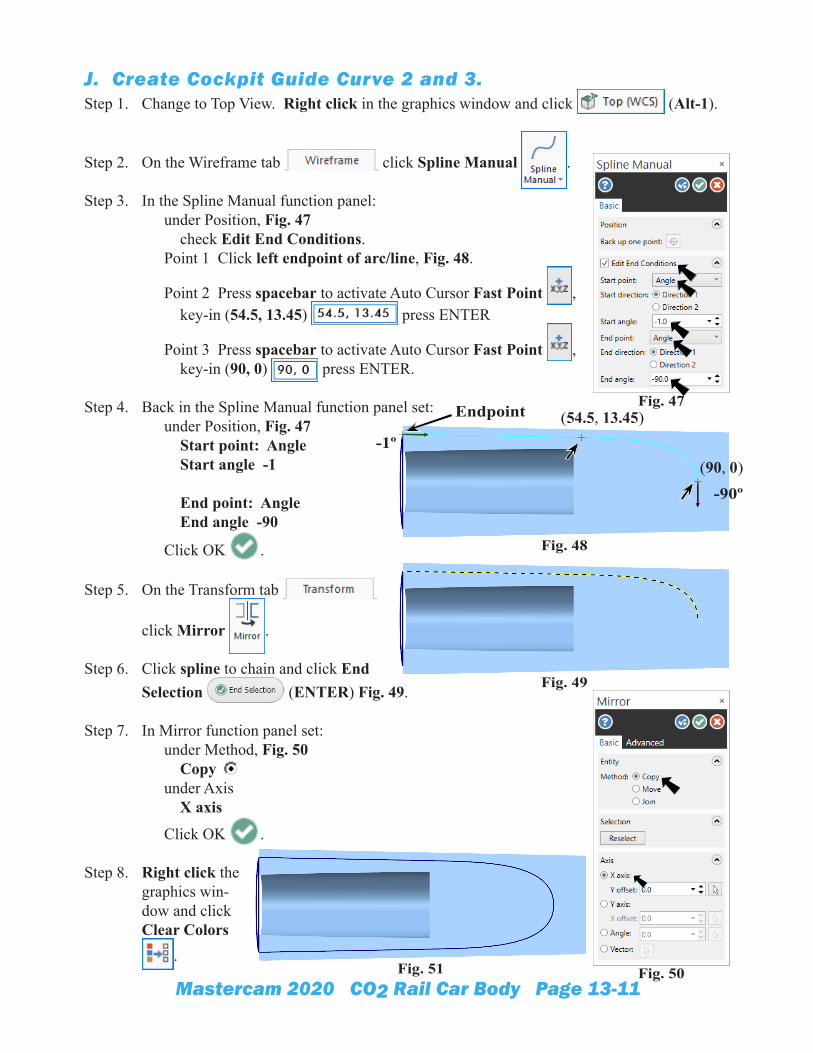
J. Create Cockpit Guide Curve 2 and 3.Step 1. Change to Top View. Right click in the graphics window and click (Alt-1).
Step 2. On the Wireframe tab click Spline Manual .
Step 3. In the Spline Manual function panel: under Position, Fig. 47 check Edit End Conditions. Point 1 Click left endpoint of arc/line, Fig. 48.
Point 2 Press spacebar to activate Auto Cursor Fast Point , key-in (54.5, 13.45) press ENTER
Point 3 Press spacebar to activate Auto Cursor Fast Point , key-in (90, 0) press ENTER.
Step 4. Back in the Spline Manual function panel set: under Position, Fig. 47 Start point: Angle Start angle -1 End point: Angle End angle -90
Click OK .
Step 5. On the Transform tab
click Mirror .
Step 6. Click spline to chain and click End Selection (ENTER) Fig. 49.
Step 7. In Mirror function panel set: under Method, Fig. 50 Copy under Axis X axis
Click OK .
Step 8. Right click the graphics win-dow and click Clear Colors
.
Fig. 47
Fig. 50
Fig. 48
Endpoint (54.5, 13.45)
(90, 0)-1º
-90º
Fig. 49
Fig. 51
Mastercam 2020 CO2 Rail Car Body Page 13-12
K. Create Cockpit Guide Curve 4.Step 1. Switch back to Top WCS.
In the Planes Manager (Alt-L) set: under Name, Fig. 52 Click Top Click Set All .
Step 2. Change to Front View. Right click in the graphics window and click (Alt-2).
Step 3. Rotate view to view right endpoints of guide curves 2 and 3. Use Alt down arrow key one time.
Step 4. On the Wireframe tab click Spline Manual .
Step 5. In the Spline Manual function panel: under Position, Fig. 53 check Edit End Conditions. Point 1 Click guide curve at top of arc midpoint .
Point 2 Press spacebar to activate Auto Cursor Fast Point , key-in (26, 12.5) press ENTER, Fig. 54. Point 3 Press spacebar, key-in (72.7, 14.3) press ENTER. Point 4 Click right endpoint of guide curve 2 press ENTER.
Step 6. Back in the Spline Manual function panel set: under Position, Fig. 53 Start point: Angle Start angle -13 End point: Angle End angle -56
Click OK .
Step 7. Save (Ctrl-S).
Fig. 52
Fig. 53
Fig. 54
Fig. 55
-13º
(26, 12.5) (72.7, 14.3)
-56º
Mastercam 2020 CO2 Rail Car Body Page 13-13
L. Create Flat Boundary Surfaces.Step 1. In the Levels Manager (Alt-Z), Fig. 56.
Hide Solids level. To hide, click to remove X in Visible column of Solids level.
Step 2. Change to the Isometric View. Right click in the graphics window and click (Alt-7).
Step 3. On the Surfaces tab click Flat Boundary .
Step 4. Click the Chain (C) in the Chaining dialog box, Fig. 57.
Step 5. Click left end of arc and walk chain to line of guide curve 1, Fig. 58.To walk chain around arc and line two methods can be used:
1) Click arc to start chain and at branch point, click Adjust to
direct chain (red axis) to line and click Next . 2) Or click arc to start chain and at branch point click the line to redirect the chain. If you select the wrong entity, click Unselect .
Step 6. Click the OK in the Chaining dialog box when chain is complete.
Step 7. In Flat Boundary Surface function panel click OK and Create New Operation , Fig. 59.
Fig. 56
Fig. 57Fig. 59
Fig. 60Fig. 58
Chain
Mastercam 2020 CO2 Rail Car Body Page 13-14
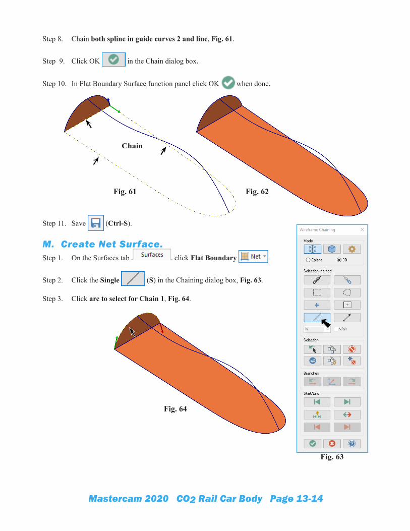
Step 8. Chain both spline in guide curves 2 and line, Fig. 61.
Step 9. Click OK in the Chain dialog box.
Step 10. In Flat Boundary Surface function panel click OK when done.
Step 11. Save (Ctrl-S).
M. Create Net Surface.Step 1. On the Surfaces tab click Flat Boundary .
Step 2. Click the Single (S) in the Chaining dialog box, Fig. 63.
Step 3. Click arc to select for Chain 1, Fig. 64.
Fig. 62Fig. 61
Chain
Fig. 63
Fig. 64
Mastercam 2020 CO2 Rail Car Body Page 13-15
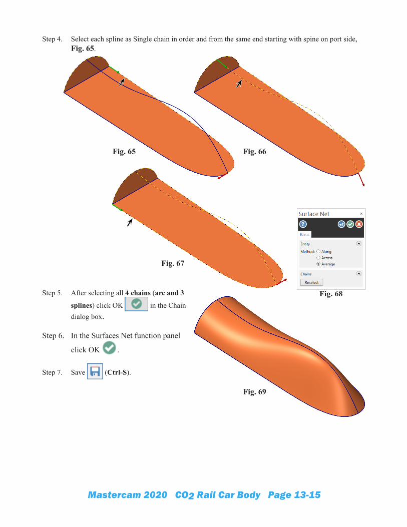
Step 4. Select each spline as Single chain in order and from the same end starting with spine on port side, Fig. 65.
Step 5. After selecting all 4 chains (arc and 3
splines) click OK in the Chain dialog box.
Step 6. In the Surfaces Net function panel
click OK .
Step 7. Save (Ctrl-S).
Fig. 68
Fig. 65 Fig. 66
Fig. 67
Fig. 69
Mastercam 2020 CO2 Rail Car Body Page 13-16
N. Solid From Surfaces.Step 1. In the Levels Manager (Alt-Z), Fig. 70.
Make Solids level active . To make active, click Solids level in the Number column.
Step 2. On the Solids tab click From Surface .
Step 3. Use Ctrl-A to select all and click End Selection (ENTER).
Step 4. In the From Surfaces function panel set: under Selection, Fig. 72 confirm 3 surfaces under Original surface select Keep
Click OK .Allow Mastercam a moment to calculate.
Step 5. In the Levels Manager (Alt-Z) Hide Cockpit Geometry level. To hide, click to remove X in Visible column of Geometry level, Fig. 73.
Step 6. Save (Ctrl-S).
Fig. 72
Fig. 70
Fig. 71
Fig. 74
Fig. 73
Mastercam 2020 CO2 Rail Car Body Page 13-17
O. Boolean Add.
Step 1. On the Solids tab click Boolean .
Step 2. Select car body for target, Fig. 75.
Step 3. In the Boolean function panel set: under Tool Bodies, Fig. 76
click Add Selection click the cockpit solid, Fig. 75 click OK in Solid Selections panel, Fig. 77.
Click OK .
P. Cartridge Hole.Step 1. Let's take a look at the cartridge hole. Hold
down middle mouse button (wheel) and drag to rotate view, Fig. 79.
Step 2. Display Solids Manager. Use Alt-I.
Step 3. In the Solids Manager: Grab the Simple solid (hole) operation, Fig. 78. Drag down and place Move arrow over Boolean Add solid and release to position Simple after Boolean Add, Fig. 80.
Step 4. On the Model Prep tab
click Clear All .
Step 5. Save (Ctrl-S).
Fig. 76 Fig. 77
Fig. 75
Tool
Target
Fig. 78
Fig. 80
Fig. 79
Fig. 81
Mastercam 2020 CO2 Rail Car Body Page 13-18
Q. Front Wheel Standoff.Step 1. Change to Front View. Right click in the graphics window and click (Alt-2).
Step 2. In the Levels Manager (Alt-Z), Fig. 82. Add new Standoff Geometry level and make active . To add level, key-in 5 in Number field and Standoff Ge-ometry in Name field. Click 5 in Number column to make Standoff Geometry level active .
Step 3. Use Ctrl-T to toggle Translucency on.
Step 4. On the Wireframe tab click Curve One Edge
.
Step 5. In Curve on One Edge function panel: Click edge of front axle hole, Fig. 84.
Click OK .
Fig. 82
Fig. 83Fig. 84
Mastercam 2020 CO2 Rail Car Body Page 13-19
Step 6. On the Wireframe tab click Spline Manual .
Step 7. In the Spline Manual function panel: under Position, Fig. 85 check Edit End Conditions. Sketch a 3 point spline for front wheel standoff.
Point 1 Press spacebar to activate Auto Cursor Fast Point , key-in (199, -34) press ENTER, Fig. 86.
Point 2 Press spacebar to activate Auto Cursor Fast Point , key-in (235, -16) press ENTER.
Point 3 Press spacebar to activate Auto Cursor Fast Point , key-in (255, -34) press ENTER.
Step 8. Back in the Spline Manual function panel set: under Position, Fig. 85 Start point: Angle Start angle 50 End point: Angle End angle -16 Click OK .
Step 9. On the Wireframe tab click Line Endpoints .
Step 10. In the Line Endpoints function panel: Sketch line across the endpoints of spline, Fig 87.
Click OK .
Step 11. Save (Ctrl-S).
Fig. 85
Fig. 86
Fig. 87
(199, -34)(199, -34)
50º -16º
(235, -16)
Mastercam 2020 CO2 Rail Car Body Page 13-20
R. Rear Wheel Fender.Step 1. On the Wireframe tab click Circle Center Point
.
Step 2. In the Circle Center Point function panel: under Size, Fig. 88 Radius 24.5 and press ENTER Click center point of circular edge of rear axle hole, Fig. 89. To locate the center of axle hole, hover cursor over left quad circle edge and green is displayed, hover over right quad until green , then click red .
Click OK .
Step 3. On the Wireframe tab click
Line Endpoints .
Step 4. In the Line Endpoints function panel: under Type, Fig. 90 select Freeform under Method select Two endpoints Click circle for first endpoint.
Press spacebar to for Fast Point Key-in coordinates (0, .68) and press ENTER.
Click OK .
Fig. 88
(0, .68)
Fig. 90
Fig. 89
Fig. 91
(16, -25)
Tip: Use Analyze F4to confirm circle
center point
Mastercam 2020 CO2 Rail Car Body Page 13-21
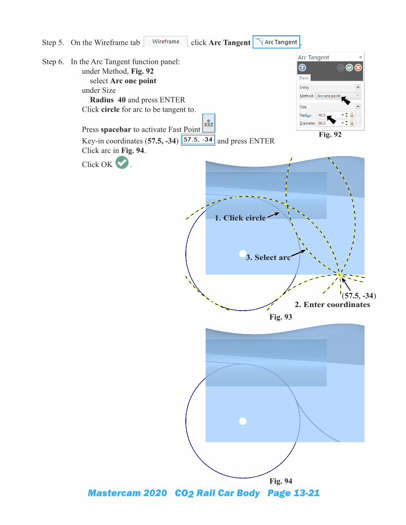
Step 5. On the Wireframe tab click Arc Tangent .
Step 6. In the Arc Tangent function panel: under Method, Fig. 92 select Arc one point under Size Radius 40 and press ENTER Click circle for arc to be tangent to.
Press spacebar to activate Fast Point Key-in coordinates (57.5, -34) and press ENTER Click arc in Fig. 94.
Click OK .
Fig. 92
Fig. 93
(57.5, -34)
1. Click circle
2. Enter coordinates
3. Select arc
Fig. 94
Mastercam 2020 CO2 Rail Car Body Page 13-22
Step 7. On the Wireframe tab click Trim to Entities .
Step 8. In the Trim to Entities function panel: under Method, Fig. 95 use default Auto Trim circle to line, Fig. 96. Select top of circle first. Trim circle to arc, Fig. 97 Click OK . Fig. 95
Fig. 96
Fig. 97
Click circle first
Click circle first
Mastercam 2020 CO2 Rail Car Body Page 13-23
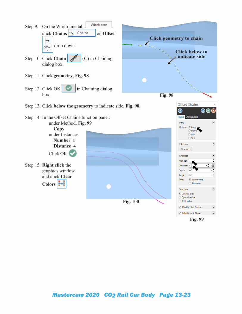
Step 9. On the Wireframe tab click Chains on Offset
drop down.
Step 10. Click Chain (C) in Chaining dialog box.
Step 11. Click geometry, Fig. 98.
Step 12. Click OK in Chaining dialog box.
Step 13. Click below the geometry to indicate side, Fig. 98.
Step 14. In the Offset Chains function panel: under Method, Fig. 99 Copy under Instances Number 1 Distance 4 Click OK .
Step 15. Right click the graphics window and click Clear Colors .
Fig. 99
Fig. 98
Click geometry to chain
Click below to indicate side
Fig. 100
Mastercam 2020 CO2 Rail Car Body Page 13-24
Step 16. On the Wireframe tab click Trim to Entities .
Step 17. In the Trim to Entities function panel: use default Auto Trim offset to rear solid edge. Click offset first, Fig. 102. Trim offset to bottom solid edge, Fig. 103. Click OK .
Fig. 101
Fig. 102
Fig. 103
Mastercam 2020 CO2 Rail Car Body Page 13-25
Step 18. On the Wireframe tab click Line Endpoints .
Step 19. In the Line Endpoints function panel: Press the E key on keyboard to configure Auto Cursor behavior of your cursor to snap to Endpoints. Also, toggle Auto Cursor Lock on Selection bar, Fig. 104. Sketch a vertical line from rear end-point of original line to endpoint of offset, Fig. 105 and Fig. 106. Click the line near the endpoint and Endpoint Auto Cursor will snap to endpoint. Click OK and Create New Opera-tion . Sketch a horizontal line to cap the geometry, Fig. 107 and Fig. 108.
Click OK .
Step 20. Save (Ctrl-S).
Fig. 104
Fig. 105
Fig. 106
Fig. 107
Fig. 108
Mastercam 2020 CO2 Rail Car Body Page 13-26
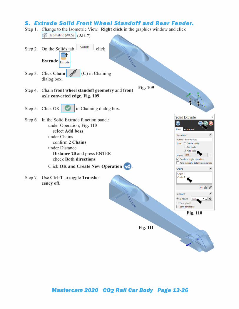
S. Extrude Solid Front Wheel Standoff and Rear Fender.Step 1. Change to the Isometric View. Right click in the graphics window and click
(Alt-7).
Step 2. On the Solids tab click
Extrude .
Step 3. Click Chain (C) in Chaining dialog box.
Step 4. Chain front wheel standoff geometry and front axle converted edge, Fig. 109.
Step 5. Click OK in Chaining dialog box.
Step 6. In the Solid Extrude function panel: under Operation, Fig. 110 select Add boss under Chains confirm 2 Chains under Distance Distance 20 and press ENTER check Both directions Click OK and Create New Operation .
Step 7. Use Ctrl-T to toggle Translu-cency off.
Fig. 110
Fig. 111
Fig. 109
Mastercam 2020 CO2 Rail Car Body Page 13-27
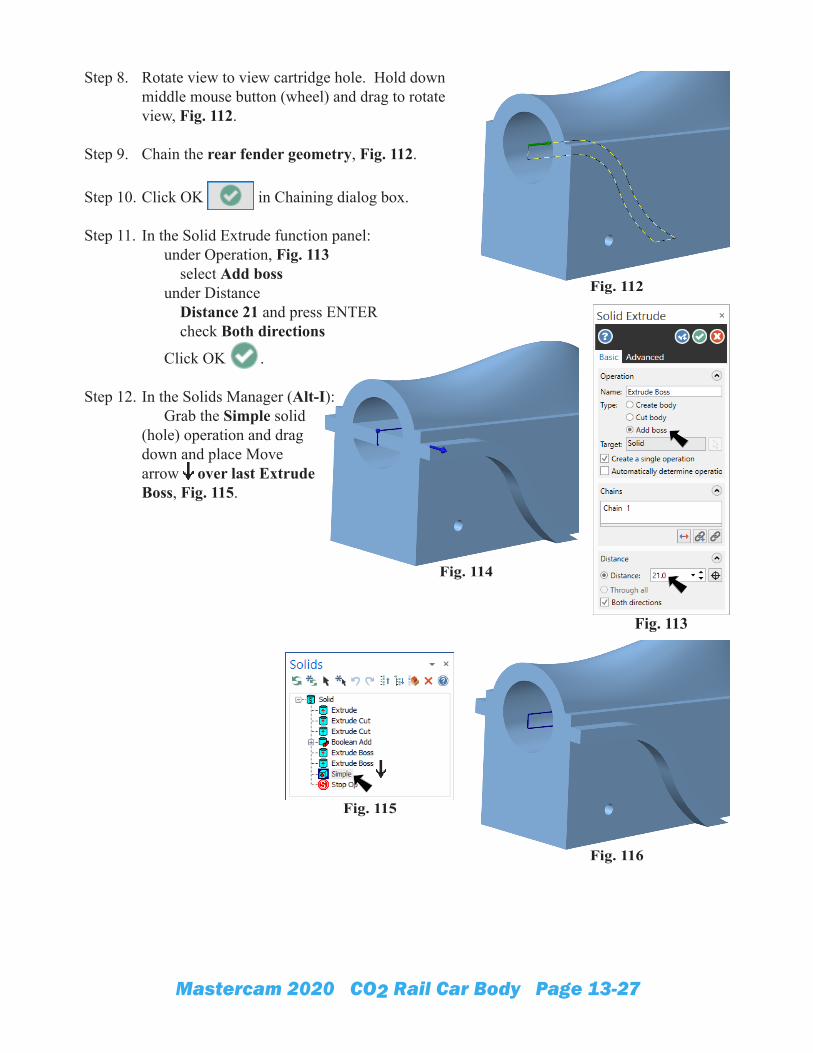
Step 8. Rotate view to view cartridge hole. Hold down middle mouse button (wheel) and drag to rotate view, Fig. 112.
Step 9. Chain the rear fender geometry, Fig. 112.
Step 10. Click OK in Chaining dialog box.
Step 11. In the Solid Extrude function panel: under Operation, Fig. 113 select Add boss under Distance Distance 21 and press ENTER check Both directions
Click OK .
Step 12. In the Solids Manager (Alt-I): Grab the Simple solid (hole) operation and drag down and place Move arrow over last Extrude Boss, Fig. 115.
Fig. 112
Fig. 113
Fig. 114
Fig. 115
Fig. 116
Mastercam 2020 CO2 Rail Car Body Page 13-28
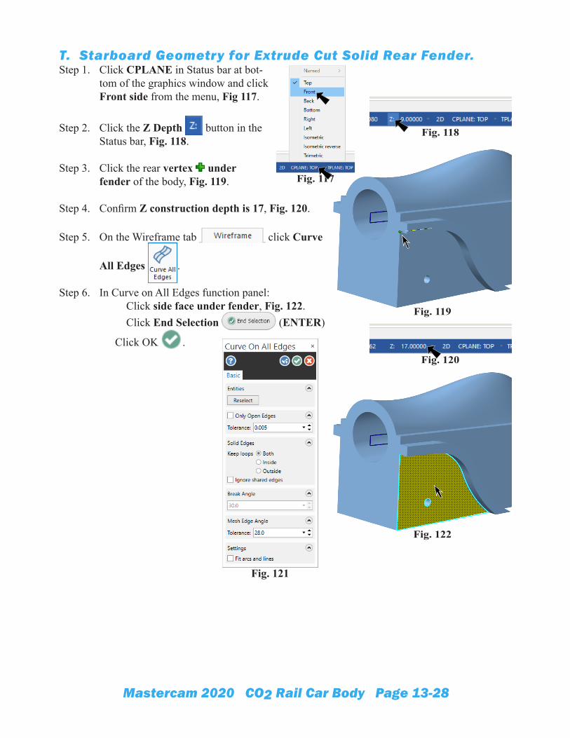
T. Starboard Geometry for Extrude Cut Solid Rear Fender.Step 1. Click CPLANE in Status bar at bot-
tom of the graphics window and click Front side from the menu, Fig 117.
Step 2. Click the Z Depth button in the Status bar, Fig. 118.
Step 3. Click the rear vertex under fender of the body, Fig. 119.
Step 4. Confirm Z construction depth is 17, Fig. 120.
Step 5. On the Wireframe tab click Curve
All Edges .
Step 6. In Curve on All Edges function panel: Click side face under fender, Fig. 122. Click End Selection (ENTER)
Click OK .
Fig. 117
Fig. 118
Fig. 120
Fig. 119
Fig. 122
Fig. 121
Mastercam 2020 CO2 Rail Car Body Page 13-29
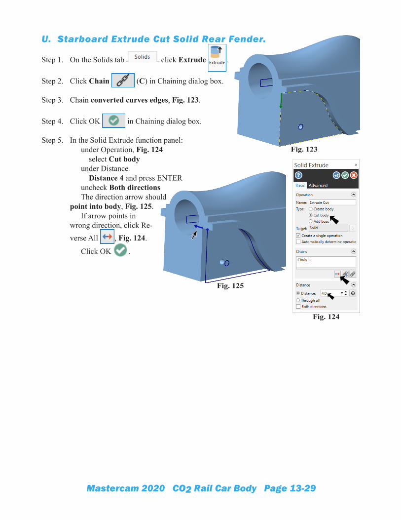
U. Starboard Extrude Cut Solid Rear Fender.
Step 1. On the Solids tab click Extrude .
Step 2. Click Chain (C) in Chaining dialog box.
Step 3. Chain converted curves edges, Fig. 123.
Step 4. Click OK in Chaining dialog box.
Step 5. In the Solid Extrude function panel: under Operation, Fig. 124 select Cut body under Distance Distance 4 and press ENTER uncheck Both directions The direction arrow should point into body, Fig. 125. If arrow points in wrong direction, click Re-verse All , Fig. 124.
Click OK .
Fig. 123
Fig. 124
Fig. 125
Mastercam 2020 CO2 Rail Car Body Page 13-30
V. Mirror Fender Geometry.Step 1. Click CPLANE in Status bar at bottom of the graphics window and
click Top side from the menu, Fig 126.
Step 2. On the Transform tab click Mirror .
Step 3. Shift click the geometry and click End Selection (EN-TER) Fig. 127.
Step 4. In Mirror function panel set: under Method, Fig. 128 Copy under Axis X axis
Click OK .
Step 5. Use Ctrl-T to toggle Translucency on.
Fig. 127
Fig. 128
Fig. 130
Fig. 126
Fig. 129
Mastercam 2020 CO2 Rail Car Body Page 13-31
W. Port Extrude Cut Solid Rear Fender.
Step 1. On the Solids tab click Extrude .
Step 2. Click Chain (C) in Chaining dialog box.
Step 3. Chain mirrored geometry, Fig. 131.
Step 4. Click OK in Chaining dialog box.
Step 5. In the Solid Extrude function panel: under Operation, Fig. 132 select Cut body under Distance Distance 4 and press ENTER The direction arrow should point into body, Fig. 133. If arrow points in wrong direction, click Reverse All , Fig. 132.
Click OK .
Step 6. Use Ctrl-T to toggle Translucency off.
Step 7. In the Levels Manager (Alt-Z), Fig. 134. Make Solids level active and hide Standoff Geometry level. To make active, click 2 in Number column to make Solids level active . To hide Standoff Geometry level, click to remove X in Visible column of Standoff Geometry level.
Step 8. In the Solids Manager (Alt-I): Right click Front Standoff Extrude Boss and click Suppress from the menu, Fig. 135.
Step 9. Save (Ctrl-S).
Fig. 131
Fig. 132
Fig. 133
Fig. 134Fig. 135
Fig. 136
Mastercam 2020 CO2 Rail Car Body Page 13-32
X. Variable Fillets.Step 1. Change to the Isometric View. Right click in the graphics window and click
(Alt-7).
Step 2. On the Solids tab click Variable Fillet on Constant Fillet
drop down.
Step 3. In the Solid Selections panel: Shift click top edge on both sides of the body select the 2 edge both sides, Fig. 138. Click OK .
Step 4. In the Variable Radius Fillet function panel: under Selection, Fig. 139 confirm 4 Edges under Radius Radius 3 click Set all button click Cycle button key-in radius into input box and press ENTER, Fig. 140. 10 in front 6 above front axle. Keep rear at default 3.
Click OK when done.
Step 5. Save (Ctrl-S).
Fig. 137
Fig. 140
Fig. 138
Fig. 139
Mastercam 2020 CO2 Rail Car Body Page 13-33
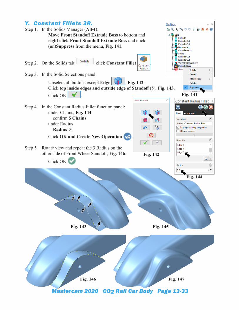
Y. Constant Fillets 3R.Step 1. In the Solids Manager (Alt-I):
Move Front Standoff Extrude Boss to bottom and right click Front Standoff Extrude Boss and click (un)Suppress from the menu, Fig. 141.
Step 2. On the Solids tab click Constant Fillet .
Step 3. In the Solid Selections panel:
Unselect all buttons except Edge , Fig. 142. Click top inside edges and outside edge of Standoff (5), Fig. 143. Click OK .
Step 4. In the Constant Radius Fillet function panel: under Chains, Fig. 144 confirm 5 Chains under Radius Radius 3 Click OK and Create New Operation .
Step 5. Rotate view and repeat the 3 Radius on the other side of Front Wheel Standoff, Fig. 146.
Click OK .Fig. 142
Fig. 145
Fig. 146 Fig. 147
Fig. 143
Fig. 144
Fig. 141
Mastercam 2020 CO2 Rail Car Body Page 13-34
Z. Face to Face Fillets.Step 1. On the Solids tab click Face to Face Fillet on Constant
Fillet drop down.
Step 2. In the Solid Selections panel: Click side face of body and variable fillet for First face set, Fig. 149. Click OK . Click the 3 top face of fender for Second face set, Fig. 150. Click OK .
Step 3. In the Constant Radius Fillet function panel: under Selection 1, Fig. 151 confirm 2 Faces and 3 Faces Section 2 under Radius Radius 3 Click OK and Create New Operation .
Fig. 151
Fig. 148
Fig. 149
Fig. 150 Fig. 152
First set
Second set
Mastercam 2020 CO2 Rail Car Body Page 13-35
Step 4. Rotate view and repeat the Face to Face Fillet 3 Radius on the other fender, Fig. 153. Click
OK .
AA. Constant Fillets 2R.Step 1. On the Solids tab click Constant
Fillet .
Step 2. In the Solid Selections panel:
Unselect all buttons except Edge . Shift click top outside edge of both fenders, Fig. 155. Click OK .
Step 3. In the Constant Radius Fillet function panel: under Chains, Fig. 156 confirm 6 Chains under Radius Radius 2
Click OK .
Step 4. Save (Ctrl-S).
Fig. 153
Fig. 155
First setSecond set
Fig. 156Fig. 157
Shift click
Shift click
Fig. 154
Mastercam 2020 CO2 Rail Car Body Page 13-36
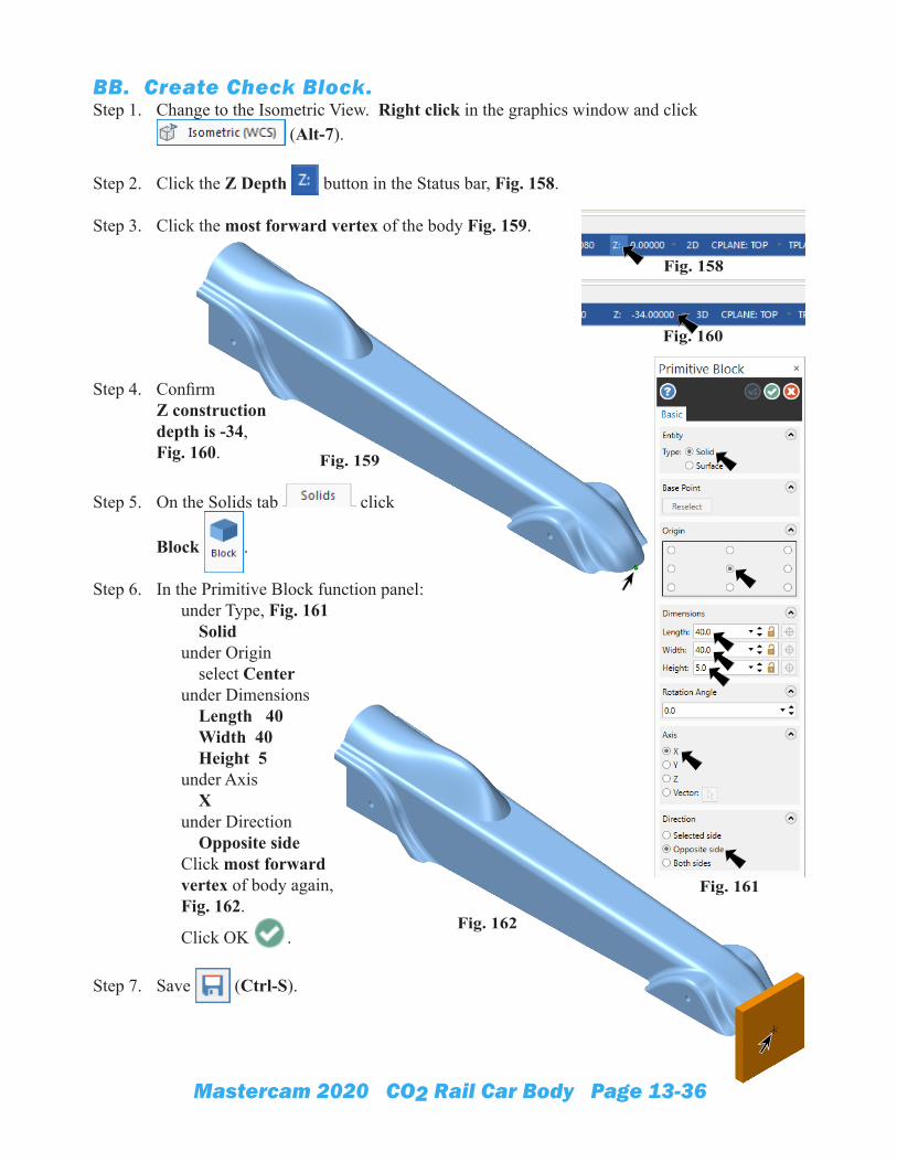
BB. Create Check Block.Step 1. Change to the Isometric View. Right click in the graphics window and click
(Alt-7).
Step 2. Click the Z Depth button in the Status bar, Fig. 158.
Step 3. Click the most forward vertex of the body Fig. 159.
Step 4. Confirm Z construction depth is -34,Fig. 160.
Step 5. On the Solids tab click
Block .
Step 6. In the Primitive Block function panel: under Type, Fig. 161 Solid under Origin select Center under Dimensions Length 40 Width 40 Height 5 under Axis X under Direction Opposite side Click most forward vertex of body again, Fig. 162.
Click OK .
Step 7. Save (Ctrl-S).
Fig. 158
Fig. 160
Fig. 159
Fig. 162
Fig. 161
Mastercam 2020 CO2 Rail Car Body Page 13-37
CC. Create LEFT CUT WCS Plane.Step 1. Toggle axes on. Use F9.
Step 2. Display the Planes Manager. Use Alt-L.
Step 3. In the Planes Manager:
Click Create a new plane drop down and select Relative to WCS > Back, Fig. 163.
Step 4. In the New Plane function panel: under Name, Fig. 164 Key-in LEFT CUT for name Origin X 0 Origin Y 34 Origin Z 0
Click OK .
Step 5. Back in the Planes Manager: Right click the new LEFT CUT plane and click Rotate incremental from menu, Fig. 165.
Step 6. In the Rotate plane dialog box set: Z 180, Fig. 166. Click OK .
Step 7. Back in the Planes Manager: Click Set All , Fig. 167.
Step 8. Change to the Isometric View. Right click in the graphics win-dow and click (Alt-7).
Step 9. Confirm LEFT CUT Origin. Click new LEFT CUT plane to view gnomon, Fig. 168.
Step 10. Save (Ctrl-S).
Fig. 163
Fig. 164
Fig. 165
Fig. 166
Tip: X axis always runs positive from Origin to front of car. Y axis always runs to right across car.