66
MASTERCAM TOOL DESIGNER TUTORIAL August 2018

MASTERCAM TOOLDESIGNER TUTORIAL
August 2018

MASTERCAM TOOL DESIGNER TUTORIAL
August 2018© 2018 CNC Software, Inc. – All rights reserved.Software: Mastercam2019
Terms of UseUse of this document is subject to the MastercamEnd User License Agreement. The MastercamEnd User LicenseAgreement can be found at:
http://www.mastercam.com/companyinfo/legal/LicenseAgreement.aspx
Be sure you have the latest information!Informationmight have changed or been added since this document was published. The latest version of the doc-ument is installed withMastercamor can be obtained from your local Reseller. A ReadMe file (ReadMe.PDF) –installed with each release – includes the latest information about Mastercam features and enhancements.
ii

TABLE OF CONTENTS
Introduction 5
General Tutorial Requirements 5
Tool Designer Overview 7
The Tool Designer Workflow 7
Tool Designer's settings pages 8
The Tool Page 8
The Insert Page 9
The Holder Page 9
The Mating Page 10
The Setup Page 10
The Boundary Page 11
The Machine Orientation Page 11
The Compensation Page 11
The Parameters Page 12
Exercise 1: Opening Tool Designer 13
Creating a Simple Rectangular 3D Tool 17
Exercise 1: Defining the Insert 17
Exercise 2: Defining the holder 19
Exercise 3: Mating the insert to the holder 22
Exercise 4: Defining the cutting andmachine-connection planes 23
Exercise 5: Finishing the tool 25
Creating a Simple 3D Cylindrical Tool 31
Exercise 1: Defining the Insert 31
Exercise 2: Defining the holder 33
Exercise 3: Defining the cutting andmachine-connection planes 36
Exercise 4: Finishing the tool 38
Mating Inserts to Holders 41
Exercise 1: Defining the Insert 41
Exercise 2: Defining the holder 46
iii

Exercise 3: Mating the insert to the holder 49
Exercise 4: Moving the insert 50
Exercise 5: Repositioning the insert 52
Exercise 6: Finishing the tool 54
Exercise 7: Replacing the insert 56
Exercise 8: Replacing a gauge insert 57
Creating a Capto-Style Multi-Component Holder 61
Exercise 1: Defining the insert 61
Exercise 2: Defining the holder 62
Exercise 3: Finishing the tool 62
Conclusion 65
MastercamResources 65
Contact Us 65
iv

INTRODUCTIONWelcome to the Tool Designer Tutorial. These lessons explore Tool Designer's interface and teach the basic conceptsof the software, including the following topics:
l A broad look at the Tool Designer interface.
l An introduction to Tool Designer's workflow.
l An overview of each page in the Tool Designer function panel.
l The techniques needed to create a valid 3D tool.
Tutorial Goals
l Gain an understanding of basic Tool Designer functions.
l Explore the parameters required to develop a 3D tool.
l Create sample 3D tools from the included STEP files.
WARNING: Screen colors in the tutorial pictures were modified to enhance image quality; they may notmatch your Mastercam settings or the tutorial results. These color differences do not affect the lesson oryour results.
Estimated time to complete this tutorial: 4 hours
General Tutorial RequirementsAll Mastercam2019 tutorials have the following general requirements:
l Youmust be comfortable using the Windows® operating system.
l The tutorials cannot be used withMastercamDemo/Home Learning Edition. The Demo/HLE file format(emcam) is different fromMastercam (mcam), and basicMastercam functions, such as file conversions and post-ing, are unavailable.
l Each lesson in the tutorial builds on the mastery of the preceding lesson's skills. We recommend that you com-plete them in order.
l Additional filesmay accompany a tutorial. Unless the tutorial provides specific instructions on where to placethese files, store them in a folder that can be accessed from the Mastercam2019 workstation, either with thetutorial or in any location that you prefer.
l Youwill need an internet connection to view videos that are referenced in the tutorials. All videos can befound on our YouTube channel:www.youtube.com/user/MastercamTechDocs
l All Mastercam tutorials require you to configure Mastercam to work in a default Metric or Inch configuration.The tutorial provides instructions for loading the appropriate configuration file.
5

6

CHAPTER 1TOOL DESIGNER OVERVIEW
Mastercam's Tool Designer lets you create 3D tools to use when simulating your toolpaths. 3D tools give you amoreaccurate simulation result, showing collisions that might not display when using a 2D tool. The following pictureshows a 3D tool performing a facing operation inMachine Simulation.
Currently, Tool Designer supports turning tools comprised of a single insert with one or more holder entities, andalthough you can use 3D tools in bothMastercamandMastercam for SOLIDWORKS, you can only create or editthem in standalone Mastercam.
Goals
l Start Tool Designer
l Understand the Tool Designer workflow.
l Explore Tool Designer's nine pages of settings.
The Tool Designer WorkflowTool Designer comprises nine pages of settings that you complete in top-down fashion. That is, youmust fill out thepages in order, with subsequent pages being disabled until the required information in previous pages is com-pleted. Most of the values in each page auto-fill with default values. You can edit these fields as needed, but if youleave one blank, it automatically restores to its default value. Required fields, on the other hand, must be filled outby you and are outlined in red until you complete them.
Note: The standalone version of ToolManager, which you run from the Windows Start menu, does not supportlathe tooling. Youmust access Tool Designer through the Lathe Tool Manager dialog box, as you discover in thefollowing exercise.
To select a Tool Designer page, click its icon on the left of the Tool Designer panel, as shown in the first picture fol-lowing. You can also navigate between the pages using the Back andNext buttons at the bottomof the panel, asshown in the second picture following.
7

Tool Designer's settings pagesAsmentioned previously, Tool Designer comprises nine pages of settings that must be completed in top-down fash-ion. The following sections describe these pages.
The Tool Page
This is the first page youmust complete. Most of the fields have default values that you can leave as is or change asneeded. Youmust, however, fill in the Name field before you canmove on to the next page. As you can see in thefollowing image, the Tool page settings define the tool's general characteristics. When you complete this page, theInsert page becomes enabled.
8
Mastercam Tool Designer Tutorial—1: Tool Designer Overview

9
The Insert Page
This page contains general settings for the tool's insert. The one required field—the field without a default value—isModel, for which you can select a STEP file or a solidmodel from the graphics windowor SolidsManager. The fieldsavailable in the Insert page depend on the insert Type you select. Once you have specified the insert model, theHolder page becomes enabled.
The Holder Page
As on the Insert page, the holder'sModel fieldmust be filled in before you can proceed. Also like the Insert page,for the model you can select either a STEP file or solids fromMastercam's graphics windowor the SolidsManager.When you complete this page, theMating and Setup pages become enabled.
Mastercam Tool Designer Tutorial—1: Tool Designer Overview

The Mating Page
On theMating page, you specify how the tool's components fit together. Specifically, youmust tell Tool Designerhow to position the insert into the holder. This page contains no required fields.
The Setup Page
On the Setup page, you specify how the tool is oriented with respect to the machine. Youmust define the CuttingPlane andMachine Connection to move on to the next page of settings. For the cutting plane, you can select a flatplane (face) fromMastercam's graphics windowor use the Plane Selection dialog box. When you have defined therequired fields, the Boundary,Machine Orientation, and Compensation pages become enabled.
10
Mastercam Tool Designer Tutorial—1: Tool Designer Overview

11
The Boundary Page
Use the Boundary page to define a tool boundary that Mastercam can use during toolpath calculation to determinethe position of all of the tool's components. All fields on this page have default values.
The Machine Orientation Page
This page determines how the tool is positioned on the machine, as well as the direction of spindle rotation. You candefine the tool'smounting position, turret, tool angle, and default active spindle.
The Compensation Page
On this page, you specify compensation values, such as the compensation point, the compensationmethod, plungeand feed direction, and tool clearance. Youmust define the compensation point center to activate the last page,Parameters.
Mastercam Tool Designer Tutorial—1: Tool Designer Overview

The Parameters Page
This page contains basic tool parameters, cutting parameters, toolpath parameters, and coolant settings. The set-tings here are like those in the Parameters tab of the Define Tool dialog box you see when designing a 2D tool.The settings on this page change based on the insert type setting on the Insert page.
12
Mastercam Tool Designer Tutorial—1: Tool Designer Overview

13
Exercise 1: Opening Tool DesignerTo access Tool Designer, youmust first start Mastercamand then load a Lathe machine. Complete the followingexercise to see how this is done.
1. Start Mastercamusing your preferredmethod:
a. Double-click Mastercam's desktop icon.
OR
b. LaunchMastercam from the Windows Start menu.
2. Select the default metric configuration file:
a. Click the File tab.
b. Choose Configuration fromMastercam's Backstage View to open the System Configuration dialogbox.
c. Choose ...\mcamxm.config <Metric> from the Current drop-down list.
d. ClickOK.
3. Click theMachine tab.
TheMachine tab—fromwhich you can load amachine, accessmachine and control definitions, as well as startBackplot, Verify, and Simulation—displays.
4. Select Lathe, Default from the Machine Type group, as shown in the following picture.
Mastercam Tool Designer Tutorial—1: Tool Designer Overview

Mastercam creates a Lathe machine group in ToolpathsManager, as shown in the second following picture.
5. On the Lathe Turning contextual tab, choose Lathe Tool Manager.
The Tool Manager dialog box displays. In this dialog box, you can choose tools for your toolpaths, as well ascreate 2D and 3D tools.
6. In the upper pane of the Tool Manager dialog box, right-click, and choose Create 3D tool from the pop-upmenu.
The Tool Designer function panel displays, as shown in the second picture following.
14
Mastercam Tool Designer Tutorial—1: Tool Designer Overview

15
You are now ready to design your first custom3D tool, which you do in the next chapter.
Mastercam Tool Designer Tutorial—1: Tool Designer Overview

16

CHAPTER 2CREATING A SIMPLE RECTANGULAR 3D TOOL
In this chapter, you create a rectangular 3D tool usingmostly default values and easily handled insert and holdermodels. After completing this chapter, you will have a general understanding of Tool Designer's workflow.
Goals
l Load a STEP file for a rectangular tool's insert and holder.
l Mate the insert to the rectangular holder.
l Define the cutting plane andmachine-connection plane.
l Generate the tool from the data you entered and the default values.
Exercise 1: Defining the Insert1. In the Name field, type Turning Tool.
As shown in the before-and-after pictures that follow, the red outline disappears from the text box, indicatingthat this required field is complete.
2. Click the Insert icon to move to that page.
3. ClickOpen insert model, located below theModel field.
The Select file to import from dialog box appears.
17

4. Navigate to and open the file Insert1.stp, which is included with this tutorial.
The selected file name appears in theModel field, and the insert model displays inMastercam's graphics win-dow, as shown in the second picture following.
5. In the Corner radius field, enter 0.03.
18
Mastercam Tool Designer Tutorial—2: Creating a Simple Rectangular 3D Tool

19
Exercise 2: Defining the holder1. Click the Holder icon to move to that page.
2. ClickOpen holder model, located below theModel field.
3. In the Select file to import from dialog box, navigate to and select the file Holder1.stp, which is includedwith this tutorial.
Mastercam Tool Designer Tutorial—2: Creating a Simple Rectangular 3D Tool
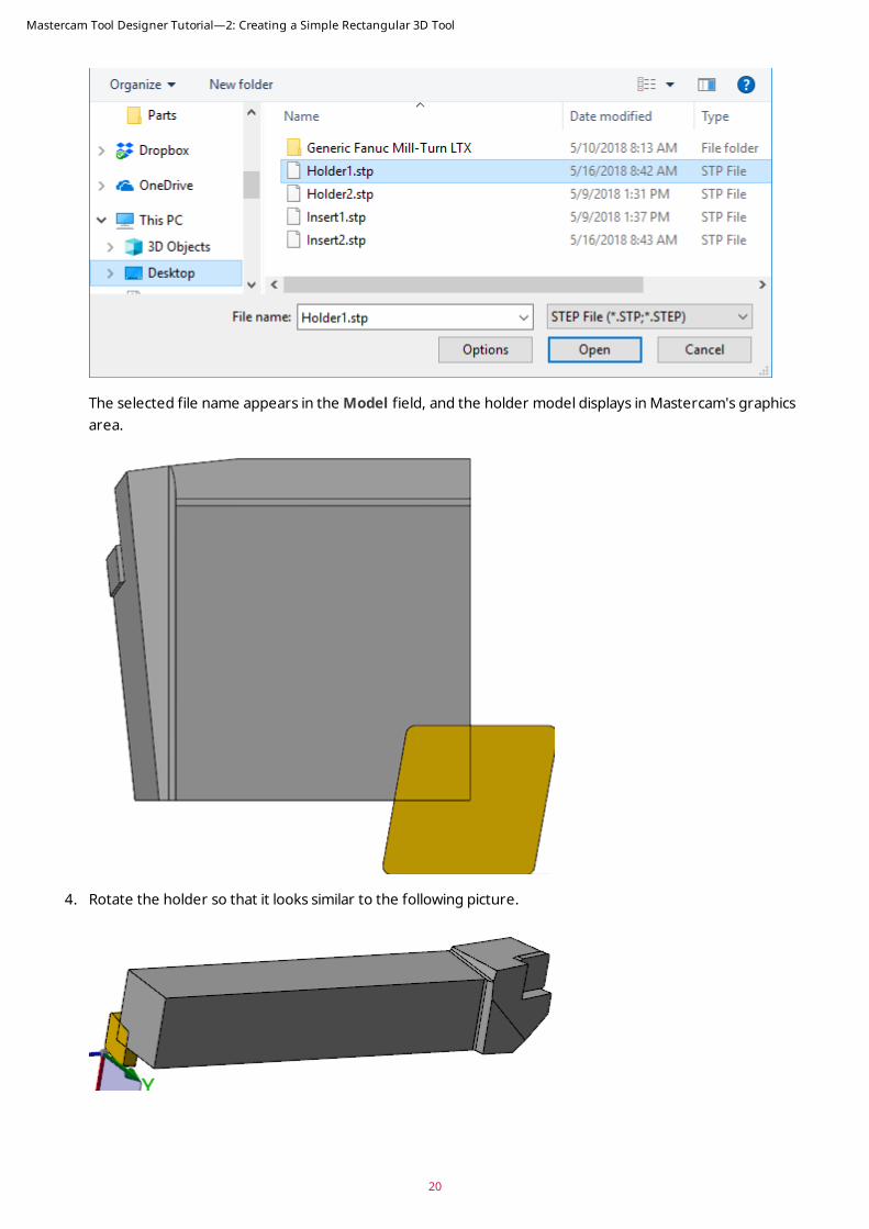
The selected file name appears in theModel field, and the holder model displays inMastercam's graphicsarea.
4. Rotate the holder so that it looks similar to the following picture.
20
Mastercam Tool Designer Tutorial—2: Creating a Simple Rectangular 3D Tool

21
5. Right-click in the Thickness field, and choose L = Length of an entity from the pop-upmenu.
6. Click the solid edge indicated in the following picture.
Mastercam sets the rectangular tool's Thickness to 25.0.
7. Right-click in theWidth field, and choose L = Length of an entity from the pop-upmenu.
8. Click the second edge, as shown in the following picture.
Mastercam sets the rectangular tool'sWidth to 25.0.
Mastercam Tool Designer Tutorial—2: Creating a Simple Rectangular 3D Tool

Exercise 3: Mating the insert to the holder1. Click theMating icon to move to that page.
2. In theMating panel, click Coincident.
Mastercamhides the holder, leaving just the insert on the screen.
3. If necessary, press [F9] to turn on the axes, and then rotate the insert so that you can see the face oppositethe one initially displayed.
22
Mastercam Tool Designer Tutorial—2: Creating a Simple Rectangular 3D Tool

23
4. Select the insert face you rotated to, as indicated in the previous picture.
The graphics window changes to display the tool holder.
5. On the holder, select the face shown in the first picture following. (To see the face, youmight need to rotatethe holder.)
Mastercamplaces the insert's selected face on top of the holder's selected face, as shown in the second fol-lowing picture.
Note: This is an over-simplified example of the mating process. More complicated, real-world scenarios arecovered later in this tutorial.
Exercise 4: Defining the cutting and machine-connection planes1. Click the Setup icon to move to that page.
Mastercam Tool Designer Tutorial—2: Creating a Simple Rectangular 3D Tool

2. In the Cutting Plane section, click Select plane, located below the Plane field.
Mastercamprompts you to select a flat solid face.
3. Rotate the part, and select the plane indicated in the following picture.
Mastercammarks the Plane field asDefined and transforms the tool.
The cutting plane is used to define the center height of the tool. It is the plane on the tool that lines up withthe centerline of the part.
4. In theMachine Connection section, click Select plane, located below the Plane field.
Mastercamprompts you to select a flat solid face.
5. Rotate the part, and select the plane indicated in the following picture.
MastercammarksMachine Connection as defined and transforms the tool.
TheMachine Connection plane is perpendicular to the projection adjustment vector of the tool. Simply, it iswhere the toolmounts into the machine or the tool locator.
24
Mastercam Tool Designer Tutorial—2: Creating a Simple Rectangular 3D Tool

25
Exercise 5: Finishing the tool1. Click the Boundary icon to move to that page.
Tool Designer generates a 2D silhouette boundary at the cutting plane, as shown (the blue and yellow lines) inthe second picture following. Mastercamuses this 2D boundary to calculate the toolpath.
2. Hover your mouse pointer over each field in the page to get an explanatory tooltip.
Mastercam Tool Designer Tutorial—2: Creating a Simple Rectangular 3D Tool

3. Click theMachine Orientation icon to move to that page.
4. Look over the fields in theMachine Orientation page, reading each of the tooltips. As with the Boundarypage, the default values in theMachine Orientation page work fine for this simplified run-through of theTool Designer workflow.
5. Click the Compensation icon to move to that page.
The Compensation page has one required field, Point, that youmust define.
26
Mastercam Tool Designer Tutorial—2: Creating a Simple Rectangular 3D Tool

27
6. Click Select compensation point.
Mastercam returns you to the graphics window to select the compensation point froma 2D representation ofthe tool.
7. Click the point shown in the following pictures. The first picture shows the point in reference to the tool, andthe second picture shows a closeup shot, detailing the exact place to click. The third picture shows the toolafter setting the compensation point.
Mastercam returns you to Tool Designer with the required Point field defined.
8. Review the other settings in the Compensation page.
Mastercam Tool Designer Tutorial—2: Creating a Simple Rectangular 3D Tool

9. Click the Parameters icon to go to that page.
As aMastercamuser, you should be familiar with the settings on this page, all of which have default values.You have seen thembefore in the Parameters tab of the Define Tool dialog box that displays when design-ing a 2D tool.
10. ClickOK to close Tool Designer and to save the tool.
ToolManager displays with your new tool added to the upper pane, as shown in the second picture following.
28
Mastercam Tool Designer Tutorial—2: Creating a Simple Rectangular 3D Tool

29
You have now completed the rectangular 3D tool. In the next chapter, you create your first cylindrical tool.
Mastercam Tool Designer Tutorial—2: Creating a Simple Rectangular 3D Tool

30

CHAPTER 3CREATING A SIMPLE 3D CYLINDRICAL TOOL
In this chapter, you create a cylindrical 3D tool, again usingmostly default values and easily managed insert andholder models. After completing this chapter, you will have additional practice with Tool Designer and will under-stand the differences between designing rectangular and cylindrical 3D tools, such as boring bars and Capto-styletools.
Goals
l Load a STEP file for a cylindrical tool's insert and holder.
l Mate the insert to the cylindrical holder.
l Define the cutting plane andmachine-connection plane.
l Generate the tool from the data you entered and the default values.
Exercise 1: Defining the Insert1. Open Tool Designer.
2. In the Name field, type Boring Bar.
3. Click the Insert icon to move to that page.
4. ClickOpen insert model, located below theModel field.
The Select file to import from dialog box appears.
31

5. Navigate to and open the file Tool2.stp, which is included with this tutorial.
The selectedmodel displays inMastercam's graphics window. Notice that this file includes both the insert andthe holder. (Rotate the tool to see the end with the insert.)
6. Click the insert.
Mastercamdisplays the insert in the graphics window.
7. Right-click the Corner radius field, and select Radius of an arc from the pop-upmenu.
This is another way to enter the Corner radius, rather than typing it as you did in the previous chapter.
8. Rotate the insert model as shown in the following picture, and select the corner radius indicated by thearrow.
A corner radius of 0.8 appears in the Corner radius field, as shown in the second picture following.
32
Mastercam Tool Designer Tutorial—3: Creating a Simple 3D Cylindrical Tool

33
Exercise 2: Defining the holder1. Click the Holder icon to move to that page.
2. ClickOpen holder model.
3. In the Select file to import from dialog box, navigate to and select the file Tool2.stp, which is included
Mastercam Tool Designer Tutorial—3: Creating a Simple 3D Cylindrical Tool
with this tutorial.
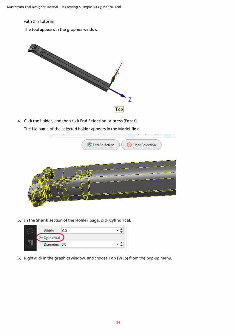
The tool appears in the graphics window.
4. Click the holder, and then click End Selection or press [Enter].
The file name of the selected holder appears in theModel field.
5. In the Shank section of the Holder page, click Cylindrical.
6. Right-click in the graphics window, and choose Top (WCS) from the pop-upmenu.
34
Mastercam Tool Designer Tutorial—3: Creating a Simple 3D Cylindrical Tool

35
7. Right-click inDiameter, and choose Diameter of an arc from the pop-upmenu.
8. Select the circular edge shown in the following image.
Mastercam sets the Diameter field to 25.4.
Mastercam Tool Designer Tutorial—3: Creating a Simple 3D Cylindrical Tool
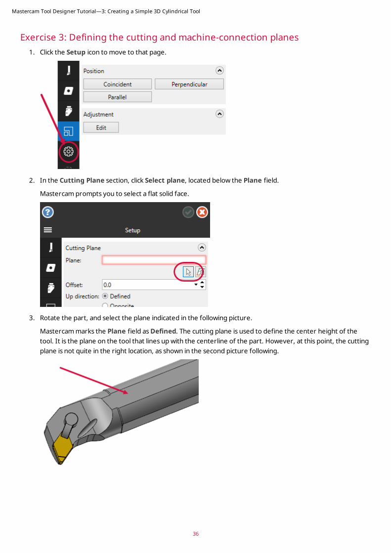
Exercise 3: Defining the cutting and machine-connection planes1. Click the Setup icon to move to that page.
2. In the Cutting Plane section, click Select plane, located below the Plane field.
Mastercamprompts you to select a flat solid face.
3. Rotate the part, and select the plane indicated in the following picture.
Mastercammarks the Plane field asDefined. The cutting plane is used to define the center height of thetool. It is the plane on the tool that lines up with the centerline of the part. However, at this point, the cuttingplane is not quite in the right location, as shown in the second picture following.
36
Mastercam Tool Designer Tutorial—3: Creating a Simple 3D Cylindrical Tool

37
4. Right-click in the Offset field, and select Z coordinate of a point from the pop-upmenu.
5. Select the arc shown in the following picture.
Mastercamuses the arc's centerpoint as the offset point, andmoves the cutting plane to the correct position,as shown in the second picture following.
Mastercam Tool Designer Tutorial—3: Creating a Simple 3D Cylindrical Tool

6. In theMachine Connection section, click Select plane, located next to the Plane field.
Mastercamprompts you to select a flat solid face.
7. Rotate the part, and select the plane indicated in the following picture.
MastercammarksMachine Connection as defined. TheMachine Connection plane is perpendicular to theprojection adjustment vector of the tool. Simply, it is where the toolmounts into the machine or the tool loc-ator.
Exercise 4: Finishing the tool1. Click the Boundary icon to move to that page.
Tool Designer generates a 2D silhouette boundary at the cutting plane, as shown (the blue and yellow lines) inthe second picture following. Mastercamuses this 2D boundary to calculate the toolpath.
38
Mastercam Tool Designer Tutorial—3: Creating a Simple 3D Cylindrical Tool

39
2. Hover your mouse pointer over each field in the page to get an explanatory tooltip.
3. Click theMachine Orientation icon to move to that page, and read the tooltips so you become familiar witheach of the fields.
4. Click the Compensation icon to move to that page.
5. Click Select compensation point with arc from tangent entities, located below the Point field.
6. Zoom in on the insert, and select the yellow lines indicated in the following picture.
Mastercam finds the finds the compensation point based ion the selected lines and sets the Point field to-0.8, 0.8, as shown in the second picture following.
Mastercam Tool Designer Tutorial—3: Creating a Simple 3D Cylindrical Tool

7. Click Tool Designer'sOK button to exit the panel and to save the tool.
Mastercamdisplays the ToolManager dialog box and adds the tool to the tool window, as shown in the secondpicture following.
You have now completed the cylindrical tool. In the next chapter, you learn to handle more complicatedmating scen-arios.
40
Mastercam Tool Designer Tutorial—3: Creating a Simple 3D Cylindrical Tool

CHAPTER 4MATING INSERTS TO HOLDERS
Probably one of the trickiest tasks in creating a 3D tool is getting the insert to mate properly to the holder. Theinsert and holder modelsmight be anywhere in 3D space, so Tool Designer features transformation tools that allowyou tomove the insert into its correct position. Often, as you have seen in previous chapters, this is just amatter ofchoosing a face on the insert and a face on the holder. In other cases, youmight need to domore detailed editing.This chapter introduces you to the tools that make this editing possible.
Exercise 1: Defining the Insert1. Load the default Lathe machine.
2. Click the file CNMG 430.5.stp, included with this tutorial, and holding down [Ctrl], drag the file into Master-cam's graphics window.
TheMerge Pattern function panel displays.
3. In theMerge Pattern function panel, clickOK.
41

4. Holding down [Ctrl], drag the second insert file (CNMG 433.stp) into Mastercam's graphics window.
5. In theMerge Pattern function panel, clickOK.
You nowhave two insert solidmodels in the graphics area, one on top of the other.
42
Mastercam Tool Designer Tutorial—4: Mating Inserts to Holders

43
6. Click the Solids tab to display the SolidsManager.
7. Open the two unnamed levels to see that there are two solid bodies in the file. These are the inserts you justbrought into Mastercam.
8. Open the Lathe ToolManager, and create a new 3D tool.
The Tool Designer panel displays.
9. In the Name field, type Testing Tool.
Mastercam Tool Designer Tutorial—4: Mating Inserts to Holders

10. Click the Insert icon to move to that page.
11. Click Select from Solids Manager, located below theModel field.
Mastercam returns you to the graphics window to select a solidmodel. In previous exercises, you selectedOpen insert model to load an insert froma file. Select from Solids Manager lets you choose the solidmodel from the SolidsManager or from the graphics window.
12. Select the insert face shown in the following picture.
Remember that you can also choose the insert from SolidsManager.
44
Mastercam Tool Designer Tutorial—4: Mating Inserts to Holders

45
13. Right-click the Corner radius field, and select Radius of an arc from the pop-upmenu.
14. Rotate the insert model as shown in the following picture, and select the corner radius indicated by thearrow.
A corner radius of 0.2032 appears in the Corner radius field.
.
Mastercam Tool Designer Tutorial—4: Mating Inserts to Holders

Exercise 2: Defining the holder1. Move to the Holder page, and clickOpen holder model.
2. In the Select file to import from dialog box, navigate to and select the file Holder3.stp, which is includedwith this tutorial.
The holder model appears in the graphics area, as shown in the second picture below.
3. Click the model to select it, and then click End Selection.
46
Mastercam Tool Designer Tutorial—4: Mating Inserts to Holders

47
The selected file name appears in theModel field. Notice that theModel field is outlined in yellow, whichmeans the modelmight need to be optimized or repaired.
4. To try to repair the model, clickOptimize. When the Optimize solid dialog box appears, clickOK.
Mastercammakes repairs and displays the Optimize solid dialog box, which shows the number of optim-izationsmade.
5. In the dialog box, clickOK.
In spite of Mastercam's optimizations, theModel field remains outlined in yellow. In this case, you can ignorethis warning, as the tool will work fine in this tutorial. If Mastercamhad been able to make all the necessarychanges, the yellow outline would not have reappeared.
6. Rotate the holder model as shown in the following picture.
Now you can see that the insert you picked for this tool is buried inside the holder.
Mastercam Tool Designer Tutorial—4: Mating Inserts to Holders

7. In the Shank section of the Holder page, click Cylindrical.
8. Right-click inDiameter, and choose Diameter of an arc from the pop-upmenu.
9. Select the circular edge shown in the following image.
Mastercam sets the Diameter field to 39.95.
48
Mastercam Tool Designer Tutorial—4: Mating Inserts to Holders

49
Exercise 3: Mating the insert to the holder1. Click theMating icon to move to that page.
2. In theMating panel, click Parallel.
Mastercamhides the holder, leaving just the insert on the screen.
3. Rotate the insert so that you can see the face shown below. (The gnomon in the picture will help you positionthe insert.)
4. Select the insert face you rotated to, as indicated in the following picture, and then pick the edge indicated.
The graphics window changes to display the tool holder.
Mastercam Tool Designer Tutorial—4: Mating Inserts to Holders

5. On the holder, select the face shown in the first picture following, and then select the edge shown. (To seethe face and edge, you need to rotate the holder.)
Mastercamaligns the insert with the holder, as shown in the third picture following.
Exercise 4: Moving the insert1. Zoom in on the insert, and notice that the insert is cutting into the holder.
The insert's position requires further editing.
50
Mastercam Tool Designer Tutorial—4: Mating Inserts to Holders

51
2. Click Edit.
Mastercam returns you to the graphics area and activates the dynamic gnomon. You are prompted to selecta face with which to position the gnomon.
3. Select the face shown in the following picture.
Mastercamnowasks you to select a line, two points, or a solid edge.
4. Select the solid edge where shown in the following picture.
Mastercamplaces the insert and displays a 2D adjustment gnomon.
5. Click the gnomon's red arrow to activate movement in the X direction.
Mastercam Tool Designer Tutorial—4: Mating Inserts to Holders

6. Move your mouse along the X axis to move the insert as shown in the following picture.
7. Click the gnomon's green arrow to activate movement in the Y direction.
8. Move your mouse along the Y axis to move the insert as shown in the following picture.
Exercise 5: Repositioning the insert1. Click the gnomon'smode button to switch to gnomonmode.
In thismode, you can position the gnomon as needed.
52
Mastercam Tool Designer Tutorial—4: Mating Inserts to Holders

53
2. Click the gnomon's origin, and then, from the AutoCursor drop-down, select Intersection.
You can nowdefine a point from the intersection of two entities.
3. Select the two edges indicated in the following picture.
Mastercampositions the gnomon at the intersection of the two lines, as shown in the second picture fol-lowing.
4. Click the gnomon button to return to translationmode.
Changes youmake now affect the geometry and not the gnomon.
Mastercam Tool Designer Tutorial—4: Mating Inserts to Holders

5. Click the gnonom's origin and then the corner indicated in the second picture following. Press [Enter] to final-ize the newposition.
Mastercamaligns the corner of the insert with the corner on the holder, completing the mating process.
6. Rotate the tool so that you can see that the insert is nowno longer cutting into the holder.
Exercise 6: Finishing the tool1. Click the Setup icon to move to that page, where you will set the cutting andmachine connection planes.
2. In the Cutting Plane section, click Select named plane, located below the Plane field.
The Plane Selection dialog box displays.
3. Select the Back plane, and clickOK.
Mastercam sets the Plane field to Back.
4. Click the Select plane button for theMachine Connection field.
54
Mastercam Tool Designer Tutorial—4: Mating Inserts to Holders

55
Mastercam returns you to the graphics area to select theMachine Connection plane.
5. Select the face indicated in the following picture.
6. Move to the Compensation page.
7. Select Select compensation point with arc from tangent entities.
8. Select the two edges indicated in the following picture.
Mastercam sets the compensation point to -0.2032, 0.2032.
Mastercam Tool Designer Tutorial—4: Mating Inserts to Holders

9. ClickOK to close Tool Designer and save the tool.
The new tool appears in ToolManager's tool list.
Exercise 7: Replacing the insert1. In ToolManager, double-click Testing Tool.
Mastercam reopens the tool in Tool Designer.
2. Go to the Insert page.
3. Click Select from Solids Manager.
4. Click Mastercam's Solids tab to open the SolidsManager.
56
Mastercam Tool Designer Tutorial—4: Mating Inserts to Holders

57
5. Select Body under Unnamed Level 1 <2>, and then double-clickUnnamed Level 1 <2>.
Mastercam replaces the current insert with the second insert in the file, positioning it exactly where the ori-ginal insert was located.
Because most insert models are positioned as specificed in an ISO standard, this is an easy way to replaceinserts in your 3D tools. Once you have manually mated one insert to the holder, others whose models aredefined in the same position automatically pop into place when selected on Tool Designer's Insert page.
Exercise 8: Replacing a gauge insert1. Start Tool Designer.
2. Name the toolGaugeInsertTool.
3. On the Insert page, clickOpen insert model.
4. Select the CNMG 433.stp file.
5. Right-click in the Corner radius field, choose R = Radius of an arc, and select a corner arc on the insert.
6. On the Holder page, clickOpen holdermodel, and choose the Holder3.stp file.
7. Rather than choose the holder geometry, choose the insert as the holder.
Mastercam Tool Designer Tutorial—4: Mating Inserts to Holders

8. Go to theMating tab, and click Parallel.
9. Choose the face and edge shown in the following picture.
10. Choose the indicated face and edge on the holder/insert.
Mastercamplaces the insert on top of the geometry you selected as the holder. What you want, though, isfor the insert to be in the exact place as the gauge insert. This task requires the Edit function.
11. Click Edit, and set the gnomon to 3D by clicking the 2D icon inMastercam's Status Bar.
You nowhave a control for manipulating the Z axis.
12. Click the blue Z axis arrow, slide the insert -5.0 mm. Click and then press [Enter] to finalize the change.
58
Mastercam Tool Designer Tutorial—4: Mating Inserts to Holders

59
The inserts now share the same space.
13. Go back to the Holder page, and reload the holder file.
14. Select the holder geometry this time, and press [Enter].
Mastercamdisplays the tool with the insert that has replaced the gauge insert.
15. Click Tool Designer'sOK button to save the tool.
You have now completed the chapter onmating inserts to holders. In the next chapter, you learn to create toolsfrommultiple-component holders.
Mastercam Tool Designer Tutorial—4: Mating Inserts to Holders

60

CHAPTER 5CREATING A CAPTO-STYLE MULTI-COMPONENT HOLDER
Although 3D tools created with Tool Designer can have only a single insert, holders can comprise many com-ponents. In this chapter, you learn to create such a tool.
Goals
l Define a holder made up of several components.
l Practice using Tool Designer.
Exercise 1: Defining the insert1. Open Tool Designer.
2. In the Name field, type Capto Tool.
3. Click the Insert icon to move to that page.
4. ClickOpen insert model, located below theModel field.
5. Navigate to and open the file Tool3.stp, which is included with this tutorial.
6. Rotate the tool, and select the insert, as shown in the following picture.
7. Right-click in the Corner radius field, and select R = Radius of an arc.
8. Select the arc shown in the following picture.
Mastercam sets the Corner radius value to 0.79375.
61

Exercise 2: Defining the holder1. Go to the Holder page.
2. ClickOpen holder model.
3. Open the Tool3.stp file.
4. Select all entities except for the insert. Make sure you get the shim and the screw, as well.
This is an example of amulti-component holder. Notice that the Model field is outlined in yellow, whichmeansit may need to be optimized or repaired.
5. Click End Selection or press [Enter] to finalize your selections.
Note: If youmiss any parts of the holder, you can reload the file to start over.
6. Click the Optimize button, and dismiss the Optimize solid dialog box when it appears.
Mastercam fixes the model and removes the yellow outline from theModel field.
7. In the Shank area, click Cylindrical.
8. Right-click the Diameter field, and select Diameter of an arc from the pop-upmenu.
9. Choose the edge shown in the following picture.
Mastercam setsDiameter to 80.0.
Exercise 3: Finishing the tool1. Go to the Setup page, and click Select named plane.
2. In the Plane Selection dialog box, select the Back plane, and clickOK.
62
Mastercam Tool Designer Tutorial—5: Creating a Capto-Style Multi-Component Holder

63
3. In theMachine Connection area, click Select plane, and then select the face shown in the following picture.
4. Go to theMachine Orientation page, and set Orientation toHorizontal and Spindle Rotation to Coun-terclockwise.
5. Go to the Compensation page, and click Select compensation point with arc from tangent
entities.
6. Select the edges shown in the following picture.
7. In Tool Designer, clickOK to close the panel and to save your tool.
Mastercam Tool Designer Tutorial—5: Creating a Capto-Style Multi-Component Holder

64

65
CONCLUSIONCongratulations! You have completed the Mastercam Tool Designer Tutorial! Now that you have mastered the skillsin this tutorial, explore Mastercam's other features and functions.
Youmay be interested in other tutorials that we offer. Mastercam tutorials are being constantly developed, and wewill addmore as we complete them. Visit our website, or select Help, Tutorials from the File tab.
Mastercam ResourcesEnhance your Mastercamexperience by using the following resources:
l Mastercam Documentation—Mastercam installs a number of helpful documents for your version of softwarein the Documentation folder of your Mastercam2019 installation.
l Mastercam Help—AccessMastercamHelp by selectingHelp, Contents fromMastercam's File tab or by press-ing [Alt+H] on your keyboard.
l Mastercam Reseller—Your localMastercamReseller can help withmost questions about Mastercam.
l Technical Support—Our Technical Support department (+1 860-875-5006 or [email protected]) isopenMonday through Friday from8:00 a.m. to 5:30 p.m. USA Eastern Standard Time.
l Mastercam Tutorials—We offer a series of tutorials to help registered users become familiar with basicMastercam features and functions. Visit our website, or select Help, Tutorials fromMastercam's File tab tosee the latest publications.
l Mastercam University—MastercamUniversity, an affordable online learning platform, gives you 24/7 access toMastercam trainingmaterials. Take advantage of more than 180 videos to master skills at your own pace andhelp prepare for MastercamCertification. For more information onMastercamUniversity, please contactyour AuthorizedMastercamReseller, visit www.mastercamu.com, or email [email protected].
l Online Communities—You can find awealth of information at www.mastercam.com. For tech tips and thelatest Mastercamnews, follow us on Facebook (www.facebook.com/mastercam), Twitter(www.twitter.com/mastercam), or Google+ (plus.google.com/+mastercam). Visit our YouTube channel to seeMastercam in action (www.youtube.com/user/MastercamCadCam)! Registered users can search for inform-ation or ask questions on the MastercamWeb forum, forum.mastercam.com, or use the knowledgebase atkb.mastercam.com.
Contact Us
For questions about this or other Mastercamdocumentation, contact the Technical Documentation department byemail at [email protected].
Mastercam Tool Designer Tutorial—Conclusion

ATTENTION! UPDATES MAY BE AVAILABLE.PLEASE REFER TO MASTERCAM.COM/SUPPORT
FOR THE LATEST DOWNLOADS.


