Professional Fidelity Mastering Grade Listening L A T E R A L I T Y Mono Stereo Phonitor x V O L U M E M I N 2 3 4 5 M A X Off On MATRIX Mute SOURCE MODE OUTPUT Digital RCA XLR DIGITAL Coaxial Optical USB C R O S S F E E D 2 2 ° 3 0 ° 4 0 ° 5 5 ° A N G L E L e f t C e n t e r R i g h t VOLTAiR 120V DC Audio Rail Preamplifier & Headphone Amplifier Standard Balanced ON Phonitor x – User Manual Headphone Amplifier and Preamplifier This User Manual is optimized for Acrobat Reader. Interactive buttons may not appear in other applications.
Transcript
Professional FidelityMastering Grade Listening
LATER ALIT YMono
Stereo
Phonitor x
VOLUME
MIN
2 3 4 5 M
AX
Off On
MATRIX
Mute
SOURCE
MODE
OUTPUT
DigitalRCA
XLR
DIGITAL
CoaxialOptical
USB
CROSSFEED
22°
30° 40° 55°
ANGLE
Left
Center Right
VOLTAiR120V DC Audio Rail Preamplifier & Headphone Amplifier
StandardBalanced
ON
Phonitor x – User Manual Headphone Amplifier and Preamplifier
This User Manual is optimized for Acrobat Reader.
Interactive buttons may not appear in other applications.
The Phonitor x is the ultimate headphone amplifier. It offers connections for headphones operated both balanced and unbalanced. With up to 3.7 W output power the Phonitor x delivers an impressive performance.
The Phonitor x is not just a headphone amplifier, but also an excellent preamplifier that can drive power amplifiers or active speakers.
VOLTAiR technology is what we also call the SPL 120V Rail Technology within the Professional Fidelity series. This makes the Phonitor x an outstandig device in terms of dynamic range, signal-to-noise ratio and headroom delivering an exceptional sound experience with invincible serenity, transparancy and realness.
LATER ALIT YMono
Stereo
Phonitor x
VOLUME
MIN
2 3 4 5 M
AX
Off On
MATRIX
Mute
SOURCE
MODE
OUTPUT
DigitalRCA
XLR
DIGITAL
CoaxialOptical
USB
CROSSFEED
22°
30° 40° 55°
ANGLE
Left
Center Right
VOLTAiR120V DC Audio Rail Preamplifier & Headphone Amplifier
XLRs: balanced, Pin 2 = Hot (+) For unbalanced operation
bridge Pin 3 to GND. RCAs: Unbalanced, Tip = Hot (+)
W IRING ON BOTTOM SIDE:
DIP SWITCHES
1 ON: HP Out +22dB2 ON: HP Out +12dB3 ON: VU 0 = +10dB
4 ON: XLR Direct Out5 ON: RCA Direct Out6 ON: AMP CTL power off when listening to
SPEAKER OUTPUTSR L R L
ANALOG SOURCES DIGITAL SOURCES
AMP CTL SPEAKER OUTPUTS
LR
ANALOG SOURCES DIGITAL SOURCES
LR USBOPTICAL
AMP CTL
R
L
R
L
L L
R
COAX
IR
ContentGetting started 4
Front view 5
Rear view 6
Bottom view 7DIP switches 7
VOLTAiR – 120V Rail Technology 8Comparisons 9
Phonitor Matrix 11Basics of stereo listening 11Stereo listening with an “traditional“ headphone preamplifier 12How does the Phonitor Matrix work? 13Angle 14Crossfeed 15Setting of Crossfeed and Angle 16Adjustment of the Phonitor Matrix 18Matrix On/Off 19
Source selection 20
Output selection 21
MODE switch 22
Laterality 22
VU meters 23
AMP CTL (Amplifier Control) 24
IR Remote control 25
DIP switches 27Level increase of the headphone output 27Attenuate the sensitivity of the VU meters 27Slave Thru 28Standby of connected Performer s800 power amp when set to
Read thoroughly and follow the instructions as well as the security advices of the Quickstart which is enclosed in the scope of delivery! You can also download the Quickstart here.
By pressing the -Button you get to the table of contents.
By pressing the -Button you get to the front view of the unit.
By pressing the -Button you get to the rear view of the unit.
By pressing the -Button you get to the bottom view of the unit.
By pressing the -Button you get to the previous content.
XLRs: balanced, Pin 2 = Hot (+) For unbalanced operation
bridge Pin 3 to GND. RCAs: Unbalanced, Tip = Hot (+)
W IRING ON BOTTOM SIDE:
DIP SWITCHES
1 ON: HP Out +22dB2 ON: HP Out +12dB3 ON: VU 0 = +10dB
4 ON: XLR Direct Out5 ON: RCA Direct Out6 ON: AMP CTL power off when listening to
SPEAKER OUTPUTSR L R L
ANALOG SOURCES DIGITAL SOURCES
AMP CTL SPEAKER OUTPUTS
LR
ANALOG SOURCES DIGITAL SOURCES
LR USBOPTICAL
AMP CTL
R
L
R
L
L L
R
COAX
IR
Mains Switch 13
Mains Voltage 14
7
Bottom view
Bottom view
DIP switches
Factory setting
8
VOLTAiR – 120V Rail Technology
VOLTAiR – 120V Rail TechnologyVOLTAiR is the synonym for our 120V Rail Technology within the Professional Fidelity series. The audio signals are processed with an unequalled +/-60V DC, which corresponds to twice that of discrete operational amplifiers and four-times that of semiconductor operational amplifiers.
VOLTAiR Technology reaches outstanding technical and sonic performances. Technically especially in terms of dynamic range and headroom and sonically especially in reproducing the finest details and delivering a totally relaxed sounding audio experience. Music sounds absolutely natural.
9
VOLTAiR – 120V Rail Technology
ComparisonsThese diagrams show how our VOLTAiR Technology compares to other circuits.
The direct relation between operating level and maximum level is fundamental for the classification: the higher the operating level, the higher the maximum level a circuit can handle. And since virtually all essential acoustic and musical parameters depend on this relation, a higher operating voltage also has a positive impact on the dynamic range, distortion limit and signal-to-noise ratio.
0
20
40
60
80
100
120Volt
30 V36 V
120 V
+ / - 15 Volt + / - 18 Volt + / - 60 Volt
Operating Voltage
120
125
130
135
140
145dB
124,2
129,1
141,4
OPA 134@30 V OPA 134@36 V SPL-OP@120 V
Dynamic Range
10
VOLTAiR – 120V Rail Technology
Do bear in mind that dB scales do not represent linear but rather exponential increases. A 3 dB increase corresponds to doubling the acoustic power, +6 dB correspond to twice the sound pressure level, and +10 dB correspond to twice the perceived loudness.
When it comes to volume, the VOLTAiR Technology exhibits a performance, in regard to maximum level and dynamic range, that is twice that of common components and circuits given that its values are approximately 10 dB higher.
THD measurements show a difference of more than 3 dB compared to the OPA134 at 36 V — in terms of sound pressure level, that corresponds to an improvement of more than 50%. The operating level most commonly used for audio equipment is +/- 15 volts.
Max. Audio Level
OPA 134@30 V OPA 134@36 V SPL-OP@120 V0
5
10
15
20
25
30
35dBu
21,5 22,5
33,2
TL 071@30 V OPA 134@36 V SPL-OP@120 V-115
-113
-111
-109
-107
-105dBu
-106
-111,7
-114,2
THD&N
11
Phonitor Matrix
Phonitor Matrix
Basics of stereo listeningWhen listening to speakers sound coming from the right is not only perceived with the right ear (red line) but it is also perceived with the left ear (green line). The sensation is time delayed, lower in level and has a reduced fre-quency range (this applies to the left speaker accordingly).
Sound from the right side Sound from the left side
It arrives later because the signal travels a distance of approx. 340 meters per second and the distance from the right speaker to the left ear is longer than it is to the right ear. It is quieter and does not deliver the full frequency range, because the signal of the right speaker does not directly arrive at the left ear but is partially reflected and absorbed by the head.
12
Phonitor Matrix
Our brain determines the direction of the sound by perceiving the time delay (interaural time difference) and the level difference (interaural level difference).
Stereo listening with an “traditional“ headphone preamplifierWhen listening to music with a traditional headphone amplifier, the right ear only perceives the right signal (red line) and the left ear only perceives the left signal (green line).
The delayed and quieter signal of the respective opposite side is miss-ing. This unnatural sound irritates the ear and is stressful for our brain, because it constantly is busy trying to locate the direction of the sound.
Besides, this super-stereo-effect leads to an exaggerated stereo width. Instruments that are placed in the stereo field appear to be located much further outside than desired.
These unnatural effects are corrected by the Phonitor Matrix.
13
Phonitor Matrix
How does the Phonitor Matrix work?In simple terms, the Phonitor Matrix creates a speaker-like listening experience on headphones. It calculates the time and level differences with their specific frequency responses to deliver a true rendition of a speaker playback.
Because time and level differences are set like real loudspeaker place-ment, the brain is able to correctly identify the direction of the sound.
You can perceive a speaker-like listening experience.
All instruments appear at the correct position within the stereo image – just like it was intended when it was mixed in the studio. In comparison to a traditional headphone amplifier it provides the best conditions min-imizing hearing fatigue.
14
Phonitor Matrix
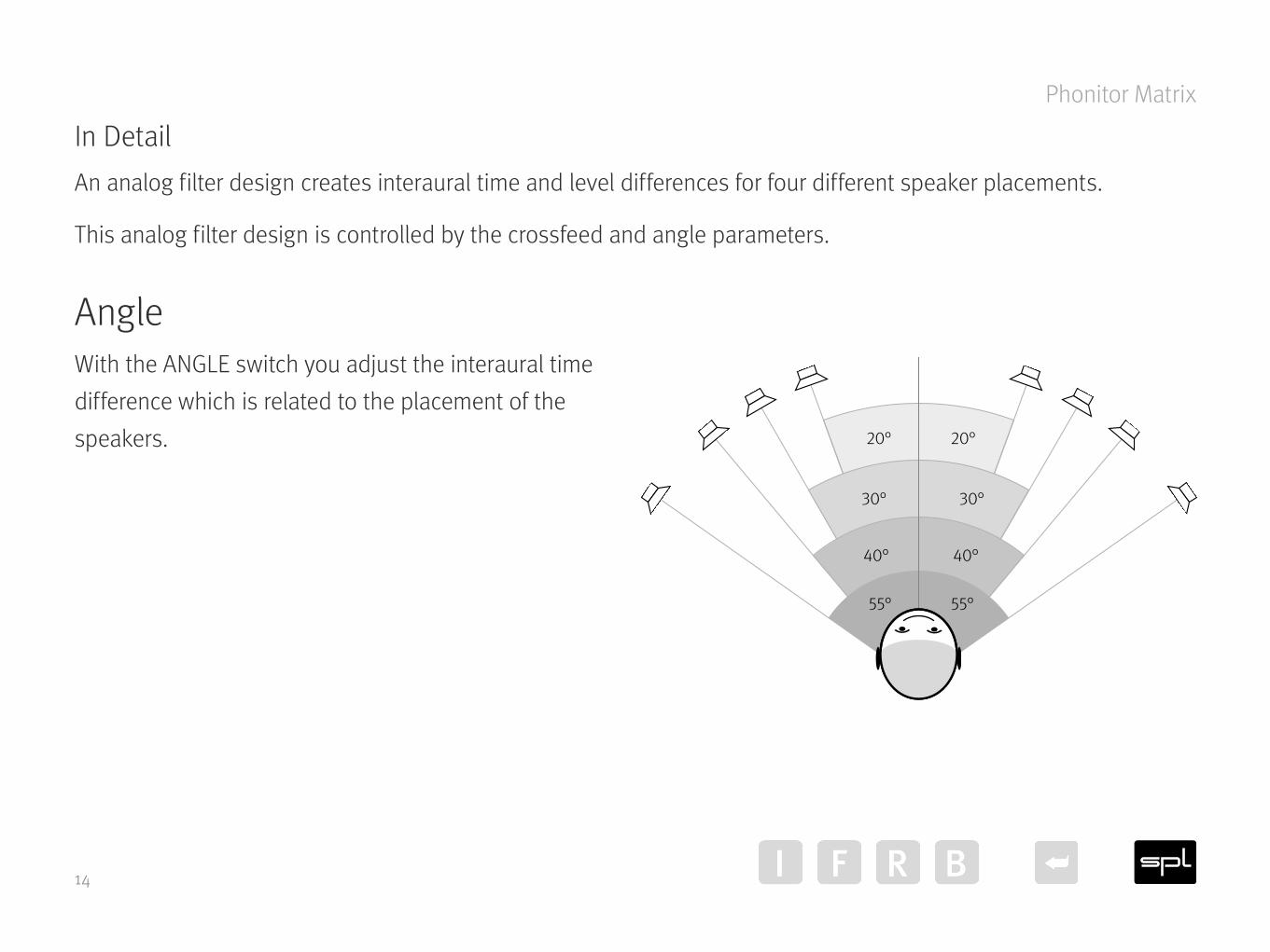
In DetailAn analog filter design creates interaural time and level differences for four different speaker placements.
This analog filter design is controlled by the crossfeed and angle parameters.
AngleWith the ANGLE switch you adjust the interaural time difference which is related to the placement of the speakers. 20°20°
30°30°
40°40°
55°55°
15
Phonitor Matrix
CrossfeedCrossfeed defines the interaural level difference. The six crossfeed values approximate the influences of room size, reflection and absorption characteristics.
The interaural level difference and the interaural time difference are frequency-corrected because the sound is reflected and absorbed by the head in a non-linear fashion.
100
0,2
0,4
0,6
0,8
1
100 1 k 10 k Hz
Frequency corrected level difference at max. Crossfeed and 30° Angle of the right channel (red = right signal, green = left signal)
10
0
50
100
150
200
µs
100 1 k 10 k Hz
Frequency corrected time difference at max. Crossfeed and 30° Angle of the right channel (red = right signal, green = left signal)
16
Phonitor Matrix
Setting of Crossfeed and AngleBoth parameters (Crossfeed and Angle) define the interaural level difference and the interaural time difference. To reproduce the exact placement of the loudspeakers, first choose the Angle parameter closest to your real speaker placement. Afterwards choose the recommended Crossfeed Parameter (see table on page 17, e.g.: Angle: 30°, Crossfeed: 3).
A vast number of factors, e.g. type of loudspeakers, room acoustics or the individual perception, influence the ste-reo-listening. This is why the Phonitor x offers six different switch positions to finely adjust the Crossfeed and to best match to your speaker playback.
Adjustment of the Phonitor MatrixBy using the CROSSFEED switch (4) and the ANGLE switch (5) you can adjust the headphone playback through the Phonitor x to your room with your loudspeaker setup.
• Play some audio material you know well with the Phonitor x and go to a place where you usually listen to music through speakers.
• Toggle between headphones and loudspeakers by using the OUTPUT switch (11).
• Set the ANGLE switch according to your loudspeaker placement (see page 14).
• Then set the CROSSFEED switch to the value that comes closest to your familiar loud-speaker-listening sound. Listen to the instruments panned in the stereo field. These instruments shall have the same positions on headphones.
LATER ALIT YMono
Stereo
VOLUME
MIN
2 3 4 5 M
AX
Off On
MATRIX
Mute
SOURCE
MODE
OUTPUT
DigitalRCA
XLR
DIGITAL
CoaxialOptical
USB
CROSSFEED
22°
30° 40° 55°
ANGLE
Left
Center Right
StandardBalanced
ON
Phonitor x
20
0%– +30 50 70 100
10 7 5 3 1 0 35
V U
20
0%– +30 50 70 100
10 7 5 3 1 0 35
V U
LATER ALIT YMono
Stereo
VOLUME
MIN
2 3 4 5 M
AX
Off On
MATRIX
Mute
SOURCE
MODE
OUTPUT
DigitalRCA
XLR
DIGITAL
CoaxialOptical
USB
CROSSFEED
22°
30° 40° 55°
ANGLE
Left
Center Right
StandardBalanced
ON
Phonitor x
20
0%– +30 50 70 100
10 7 5 3 1 0 35
V U
20
0%– +30 50 70 100
10 7 5 3 1 0 35
V U
LATER ALIT YMono
Stereo
VOLUME
MIN
2 3 4 5 M
AX
Off On
MATRIX
Mute
SOURCE
MODE
OUTPUT
DigitalRCA
XLR
DIGITAL
CoaxialOptical
USB
CROSSFEED
22°
30° 40° 55°
ANGLE
Left
Center Right
StandardBalanced
ON
Phonitor x
20
0%– +30 50 70 100
10 7 5 3 1 0 35
V U
20
0%– +30 50 70 100
10 7 5 3 1 0 35
V U
19
Phonitor Matrix
Matrix On/OffWith the MATRIX switch (3) you activate or deactivate the Matrix of the Phonitor x.
The Phonitor Matrix is available for headphone outputs only. The Speaker Outputs (19) at the rear of the unit are not fed by the Phonitor x matrix.
LATER ALIT YMono
Stereo
VOLUME
MIN
2 3 4 5 M
AX
Off On
MATRIX
Mute
SOURCE
MODE
OUTPUT
DigitalRCA
XLR
DIGITAL
CoaxialOptical
USB
CROSSFEED
22°
30° 40° 55°
ANGLE
Left
Center Right
StandardBalanced
ON
Phonitor x
20
0%– +30 50 70 100
10 7 5 3 1 0 35
V U
20
0%– +30 50 70 100
10 7 5 3 1 0 35
V U
20
Source selection
Source selectionThe Phonitor x is not just a headphone amplifier. It is also a preamplifier with up to five audio sources.
It features two analog stereo inputs – XLR and RCA (15).
Phonitor x can be equipped with a DA converter. With that installed the available inputs are expanded by USB, coaxial and optical digital stereo inputs (16).
• Select an analog audio source by using the SOURCE switch (8) – RCA or XLR.
• You can select an digital audio source (USB, coaxial, optical) by using the DIGITAL switch (9). Set the SOURCE switch to Digital.
Signals at analog RCA input (12), will be amplified from HiFi level to studio level. The sources are then equal in level when you switch between XLR and RCA (provided that a stu-dio signal is present at the XLR input).
LATER ALIT YMono
Stereo
VOLUME
MIN
2 3 4 5 M
AX
Off On
MATRIX
Mute
SOURCE
MODE
OUTPUT
DigitalRCA
XLR
DIGITAL
CoaxialOptical
USB
CROSSFEED
22°
30° 40° 55°
ANGLE
Left
Center Right
StandardBalanced
ON
Phonitor x
20
0%– +30 50 70 100
10 7 5 3 1 0 35
V U
20
0%– +30 50 70 100
10 7 5 3 1 0 35
V U
LATER ALIT YMono
Stereo
VOLUME
MIN
2 3 4 5 M
AX
Off On
MATRIX
Mute
SOURCE
MODE
OUTPUT
DigitalRCA
XLR
DIGITAL
CoaxialOptical
USB
CROSSFEED
22°
30° 40° 55°
ANGLE
Left
Center Right
StandardBalanced
ON
Phonitor x
20
0%– +30 50 70 100
10 7 5 3 1 0 35
V U
20
0%– +30 50 70 100
10 7 5 3 1 0 35
V U
21
Output selection
Output selectionWith the OUTPUT switch (11) you send an input signal to a selected output – Loudspeakers or headphones.
In the Mute position no signal passes through to the outputs. The VU meter are illuminated in red.
Set to the loudspeaker setting, the selected input signal passes through to both analog audio outputs – RCA and XLR.
Please note that the standard headphone output (13) takes priority over the balanced headphone output (12). There is no signal at the balanced headphone output if a headphone is already plugged into the standard head-phone output.
To protect the headphone power amplifier stage and guarantee a long and consistent performance please note:
• Turn down VOLUME before swapping headphones.• Never insert a mono jack plug into the front panel stereo jack.• Make sure that the headphones stereo jack is fully inserted.• If you use an adapter from 3,5 mm to 1/4" (6,35 mm) on your headphone make sure that the adapter is fully
screwed on respectively fully plugged in.
LATER ALIT YMono
Stereo
VOLUME
MIN
2 3 4 5 M
AX
Off On
MATRIX
Mute
SOURCE
MODE
OUTPUT
DigitalRCA
XLR
DIGITAL
CoaxialOptical
USB
CROSSFEED
22°
30° 40° 55°
ANGLE
Left
Center Right
StandardBalanced
ON
Phonitor x
20
0%– +30 50 70 100
10 7 5 3 1 0 35
V U
20
0%– +30 50 70 100
10 7 5 3 1 0 35
V U
22
MODE switch
MODE switchBy using the MODE switch (10) you can switch the audio signal to Stereo, Stereo with Later-ality control and Mono. In Mono mode, both stereo channels are summed. The mono signal maintains the same loudness, because both stereo channels are each reduced by 6 dB.
LateralityLaterality refers to the deviation of sound perception to either side of the ears. With the Laterality control (6) you can compensate perceived volume differences between channels that may be due to a hearing impairment.
This control differs from conventional balance controls. If one channel is attenuated, the other one is increased at the same time. This means that, e.g. when hard left, the level of the left channel increases by 2.25 dB while the right channel is attenuated by 2.25 dB.
This control has a narrower range than conventional balance controls. Its resolution is very fine, which means it can be peciseley adjusted.
Set the MODE switch to LATERALITY to control the laterality (see above).
LATER ALIT YMono
Stereo
VOLUME
MIN
2 3 4 5 M
AX
Off On
MATRIX
Mute
SOURCE
MODE
OUTPUT
DigitalRCA
XLR
DIGITAL
CoaxialOptical
USB
CROSSFEED
22°
30° 40° 55°
ANGLE
Left
Center Right
StandardBalanced
ON
Phonitor x
20
0%– +30 50 70 100
10 7 5 3 1 0 35
V U
20
0%– +30 50 70 100
10 7 5 3 1 0 35
V U
LATER ALIT YMono
Stereo
VOLUME
MIN
2 3 4 5 M
AX
Off On
MATRIX
Mute
SOURCE
MODE
OUTPUT
DigitalRCA
XLR
DIGITAL
CoaxialOptical
USB
CROSSFEED
22°
30° 40° 55°
ANGLE
Left
Center Right
StandardBalanced
ON
Phonitor x
20
0%– +30 50 70 100
10 7 5 3 1 0 35
V U
20
0%– +30 50 70 100
10 7 5 3 1 0 35
V U
23
VU meters
VU metersThe VU meters (2) display the input levels for the selected source. The meter indicates levels from -20 dB to +5 dB. 0 dB corresponds to +4 dBu.
If necessary you can lower the sensitivity by 10 dB so that the meters go up to +15 dB intput level (see ”DIP switches“ on page 27).
The ballistics of the VU meters guarantee an optimal visual perception. The time calibration of the VU meters complies with the requirements of the BBC. The rise time up to 0 dB is about 300 ms.
If the VU meters light up red permanently – even if the Phonitor x is unmuted – the protection circuit has been activated. The output connectors are disconnected from the amplifier via a relay to protect the connected head-phones. Please contact your local dealer for repair service.
LATER ALIT YMono
Stereo
VOLUME
MIN
2 3 4 5 M
AX
Off On
MATRIX
Mute
SOURCE
MODE
OUTPUT
DigitalRCA
XLR
DIGITAL
CoaxialOptical
USB
CROSSFEED
22°
30° 40° 55°
ANGLE
Left
Center Right
StandardBalanced
ON
Phonitor x
20
0%– +30 50 70 100
10 7 5 3 1 0 35
V U
20
0%– +30 50 70 100
10 7 5 3 1 0 35
V U
24
AMP CTL (Amplifier Control)
AMP CTL (Amplifier Control)If you own a SPL Performer s800 you can connect the AMP CTL (18) of the Phonitor x with a mono mini jack cable to the AMP CTL of the Performer s800 to switch both units in and out of standby together. Use a 3.5 mm mono mini jack cable.
The Phonitor x offers two outputs (A and B) in case you use two Performer s800 in bridge mode or in a bi-wiring application.
Set the DIP switch 6 on the bottom of the unit to ON to switch the Performer s800 into standby when the output selection is set to Headphone (see ”Standby of connected Performer s800 power amp when set to Headphone“ on page 28).
XLRs: balanced, Pin 2 = Hot (+) For unbalanced operation
bridge Pin 3 to GND. RCAs: Unbalanced, Tip = Hot (+)
W IRING ON BOTTOM SIDE:
DIP SWITCHES
1 ON: HP Out +22dB2 ON: HP Out +12dB3 ON: VU 0 = +10dB
4 ON: XLR Direct Out5 ON: RCA Direct Out6 ON: AMP CTL power off when listening to
SPEAKER OUTPUTSR L R L
ANALOG SOURCES DIGITAL SOURCES
AMP CTL SPEAKER OUTPUTS
LR
ANALOG SOURCES DIGITAL SOURCES
LR USBOPTICAL
AMP CTL
R
L
R
L
L L
R
COAX
IR
25
IR Remote control
IR Remote controlThe volume potentiometer can be remotely controlled using any infrared (IR) remote control.
The special feature is that the Phonitor x learns your remote and not the other way around. You do not need a univer-sal remote control. Take, for example, the remote control of the CD player. Out of the many buttons there are two you hardly use if at all. Assign Volume up / Volume down to these two buttons and let the Phonitor x learn them.
• While learning the IR remote control commands set the OUTPUT switch (11) to Mute. VU meters light up red.
• Press the PGM IR VOLUME button (17) on the rear of the unit until you note the actuation point. The Power LED now lights up brighter.
• Point your remote control towards the VU meters (2) and push the button you wish to use to lower the volume. The power LED flashes once per push. Press the same button repeatedly until the power LED flashes three times within a short interval – programming this button is then completed.
XLRs: balanced, Pin 2 = Hot (+) For unbalanced operation
bridge Pin 3 to GND. RCAs: Unbalanced, Tip = Hot (+)
W IRING ON BOTTOM SIDE:
DIP SWITCHES
1 ON: HP Out +22dB2 ON: HP Out +12dB3 ON: VU 0 = +10dB
4 ON: XLR Direct Out5 ON: RCA Direct Out6 ON: AMP CTL power off when listening to
SPEAKER OUTPUTSR L R L
ANALOG SOURCES DIGITAL SOURCES
AMP CTL SPEAKER OUTPUTS
LR
ANALOG SOURCES DIGITAL SOURCES
LR USBOPTICAL
AMP CTL
R
L
R
L
L L
R
COAX
IR
26
IR Remote control
• Point your remote control towards the VU meters (2) and push the button you wish to use to increase the volume. The power LED flashes once per push. Press the same button repeatedly until the power LED flashes three times within a short interval – programming this button is then completed.
• Learn mode ends automatically after the second button is learned.
• Please note: direct insolation of strong light (e.g. sun light, halogen lamps, neon tubes, fluorescent tubes, terrarium and aquarium lights as well as big flat screens) may lead to misoperation of the remote control functions.
27
DIP switches
DIP switchesWith the DIP switches (20) on the bottom of the unit the following settings can be chosen:
Level increase of the headphone outputBy using the DIP switches 1 and 2 you can increase the level of the headphone outputs to better feed power-hun-gry headphones.
DIP switch 1: ON = The headphone output is boosted to +22 dB.
DIP switch 2: ON = The headphone output is boosted to +12 dB.
DIP switch 1 and 2: ON = If both DIP switches 1 and 2 are ON, a boost of +24 dB is applied.
Attenuate the sensitivity of the VU metersWith DIP switch 3 you can attenuate the sensitivity of the VU meter by 10 dB. With the switch activated, a value of +15 dB input level can be displayed.
DIP switch 3: ON = The sensitivity of the VU meter is attenuated by 10 dB. In this case 0 dB on the VU meter represent a value of +10 dBu.
28
DIP switches
Slave ThruBy using DIP switches 4 and 5 the chosen input passes directly to the outputs.
DIP switch 4: ON = The chosen input passes directly to the XLR output without being affected by the volume con-trol. (Slave Thru).
DIP switch 5: ON = The chosen input passes directly to the RCA output without being affected by the volume con-trol. (Slave Thru).
Standby of connected Performer s800 power amp when set to HeadphoneBy using the DIP switch 6 units which are connected to AMP CTL ( Performer s800 power amp) are set to standby to save power when the output selection is set to Headphone.
DIP switch 6: ON = Units which are connected to AMP CTL ( Performer s800 power amp) are switched into standby to save power when the output selection is set to .
Balanced headphone output• Neutrik 4-pin XLR connector • Pin wiring: 1 = L (+), 2 = L (-), 3 = R (+), 4 = R (-)• Impedance: 0.36 ohms• Damping factor: 180 @ 40 ohms• Frequency range: 10 Hz to 300 kHz ( -3 dB)• Crosstalk at 1 kHz: -90 dB• THD & N: 0.00091 % (at 0 dBu, 1 kHz, 100 kohms load)• Noise (A-weighted): -98 dBu• Dynamic range: 130.5 dB
31
Specifications
Standard headphone outputWarning: Never connect a mono jack cable to the standard headphone output (front panel stereo jack). Make sure that the stereo jack is fully inserted, otherwise a short circuit might damage the headphone amplifier!
• 6.35 mm TRS connector• Pin wiring: Tip = Left, ring = right, sleeve = GND• Impedance: 0.18 ohm• Attenuation factor: 180 @ 40 ohms• Frequency range: 10 Hz to 300 kHz ( -3 dB)• Crosstalk at 1 kHz: -90 dB• THD & N: 0.00091% (at 0 dBu, 1 kHz, 100 kohms load)• Noise (A-weighted): -103 dB• Dynamic range: 135.5 dB
Max. Output power (at +30 dBu @ 1 kHz)• 2 x 1 W at 600 Ohm impedance• 2 x 2 W at 300 Ohm impedance• 2x 3.7 W at 120 Ohm impedance• 2x 2.9 W at 47 Ohm impedance• 2x 2.7 W at 32 Ohm impedance
32
Specifications
Line outputs• Neutrik XLR, balanced, Pin 2 = (+)• RCA, unbalanced • Frequency range: 4 Hz to 300 kHz (-3 dB)• Crosstalk at 1 kHz: -106 dB• THD & N: 0.00085 % (at 0 dBu, 1 kHz, 100 kohms load)• Noise (A-weighted): -103.8 dB• Dynamic range: 136.3 dB
Internal operating voltages• Analog: +/- 60 V• Digital: + 5 V and + 3.3 V (optional)
Power supply• Mains voltage (switchable): 230 V AC / 50 Hz or 115 V AC / 60 Hz• Fuses: 230 V: T 500 mA; 115 V: T 1 A• Power consumption: max 40 VA• Stand-by power consumption: 0.7 W
33
Specifications
Dimensions (incl. feet)• (WxHxD) 10.94 x 3.94 x 12.99 in (278 x 100 x 330 mm)
This manual includes a description of the product but no guarantee as for specific characteristics or successful results. Unless stated otherwise, everything herein corresponds to the technical status at the time of delivery of the product by SPL electronics GmbH. The design and circuitry are under continuous development and improve-ment. Technical specifications are subject to change.