147
Masterpact LV air circuit breakers ■ Merlin Gerin ■ Modicon ■ Telemecanique

MasterpactLV air circuit breakers
Merlin Gerin Modicon Telemecanique

2
3
Contents
LV air circuit breakersand switch-disconnectors
Section 1 page
Product Panorama 5
Section 2
Performance and functionality 17
Section 3
Control unit selection 31
Section 4
Accessories 55
Section 5
Source changeover systems 63
Section 6
Complementary technical information 73
Section 7
Installation and connection details 89
Section 8
Dimensions 117
Section 9
Wiring diagrams 131
Section 10
Order form 145
Masterpact: the marketleader for air circuit breakers
With a range from 800 to 6300 Amps and acomprehensive list of accessories, Masterpact canprovide solutions for all types of LV applications.
Masterpact combined with its associated range ofmoulded case circuit breakers, Compact NS offers themost advanced LV circuit protection solutions available;with unrivaled support and after sales services.

4
Help index
Description Product Page numberRated operational
voltage (Ue) M08 to M16 (AC) 18/19
M20 TO M63 (AC) 20/21
1000V AC Version 22/23
Switch Disconnectors 24/25
DC version 28/29
Short time withstand M08 to M16 (AC)
current (Icw) M20 TO M63 (AC) 20/21
1000V AC Version 22/23
Switch Disconnectors 24/25
DC version 28/29
Service breaking capacity (Ics) M08 to M16 (AC) 18/19
M20 TO M63 (AC) 20/21
1000V AC Version 22/23
Switch Disconnectors 24/25
DC version 28/29
Source changeover systems All 63/72
Tripping characteristics STR18M 74
STR28D 75
STR38D 76
STR58D 77
STR38/58 Earth fault 78
STR38/58 Load monitoring 79
STR68U 80
STR68U Earth fault 81
STR68U Load monitoring 82/83
DC applications (DINA) 85/86
STR28D 75
Ultimate breaking M08 to M16 (AC) 18/19
capacity (Icu) M20 to M63 (AC) 20/21
1000V AC version 22/23
Switch Disconnectors 24/25
DC version 28/29
Utilisation category M08 to M16 (AC) 18/19
Functionality:
M20 to M63 (AC) 20/21
1000V AC version 22/23
Switch Disconnectors 24/25
DC version 28/29
Ue M08 to M16 (AC) 18/19
M20 to M63 (AC) 20/21
1000V AC version 22/23
Switch Disconnectors 24/25
DC version 28/29
Ui M08 to M16 (AC) 18/19
M20 to M63 (AC) 20/21
1000V AC version 22/23
Switch Disconnectors 24/25
DC version 28/29
Uimp M08 to M16 (AC) 18/19
M20 to M63 (AC) 20/21
1000V AC version 22/23
Switch Disconnectors 24/25
DC version 28/29
Weights All 14/15
Wiring diagrams All 131/142
Description Product Page numberAccessories All 55/62
Tropicalisation All 9
Standards(conformity to) All 9
Installation details General 11 & 90
Safety clearances (AC) 91
Safety clearences (DC) 92
Source changeover systems 93/94
Connection details AC General 95/97
DC General 105/107
M08H/L to M16H/L (AC) 98
M20L/M25L andM32H (AC) 100
M40 (AC) 101/102
M50 to M63 (AC) 103/104
DC range 108/115
Control units Overview 32/35
General characteristics:
STR18M 36
STR28M and 38S 27
STR58U 38/39
STR68U 42/43
Functionality:
STR18M to 58U 40/41
STR68U 44/47
For DC applications (DINA) 48
Auxiliary power supplies 51/52
Accessories 49/50
DC Versions (general) All 12
Degree of protection All 10
Dimensions All 117/130
Effect on ambient temp. AC Range 84
DC range 87
Endurance - electrical M08 to M16 (AC) 18/19
M20 to M63 (AC) 20/21
1000V AC version 22/23
Switch Disconnectors 24/25
DC version 28/29
Endurance - mechanical M08 to M16 (AC) 18/19
M20 to M63 (AC) 20/21
1000V AC version 22/23
Switch Disconnectors 24/25
DC version 28/29
Ics (kA) M08 to M16 (AC) 18/19
M20 to M63 (AC) 20/21
1000V AC version 22/23
Switch Disconnectors 24/25
DC version 28/29
Icu (kA) M08 to M16 (AC) 18/19
M20 to M63 (AC) 20/21
1000V AC version 22/23
Switch Disconnectors 24/25
DC version 28/29
Rated impulse withstand M08 to M16 (AC) 18/19
voltage M20 to M63 (AC) 20/21
1000V AC version 22/23
Switch Disconnectors 24/25
DC version 28/29
Rated insulation voltage (Ui) M08 to M16 (AC) 18/19
M20 TO M63 (AC) 20/21
1000V AC Version 22/23
Switch Disconnectors 24/25
DC version 28/29

5
LV air circuit breakersand switch-disconnectors
Masterpact800 to 6300 Amp
Product Panorama
page
General characteristics 6
Installation 11
DC circuit breakers 12
Weights and dimensions 14
Section 1
1

6
Front face1 Opening push-button (O)2 Closing push-button (I)3 Keylock for "connected",
"disconnected" or "test" position4 Door interlock5 Stored-energy-mechanism charging
handle6 Operations counter7 "Open" position keylock8 Racking handle storage9 Functional position indicator:
"connected", "test" and "disconnected"10 Controls on fixed chassis (accessible
with cubicle door closed)11 Padlocking facilities for "connected",
"disconnected" or "test" position12 Stored-energy-mechanism status
indicator
"charged"
"discharged"
13 Main-contact position indicator
"OFF" (O);
"ON" (I).
14 Fault-trip indicator/breaker reset button LV circuit-breaker: blue figures
Masterpact: Product Panorama
General characteristics
Masterpact circuit breakers are used toprotect and control low-voltage distributionsystems. They may be installed in main LVswitchboards, as incoming units,bus-sections and main outgoing circuits.Masterpact is a complete range offering alarge selection of performance levels: Ratings from 800 to 6300 A AC,
from 1000 to 8000 A DC; Breaking capacity from 50 to 150 kA rms; Operational voltages 690 V AC,
1000 V DC.
Versions 3 or 4 poles; Fixed or drawout versions; Current-limiting version up to 2500 A; Wide range of control units offering
multiple functions.
Circuit breakers designed for allapplications 1000 V AC version; DC version; Versions for corrosion atmospheres; Source-changeover version; Merchant-marine and military versions.Masterpact circuit breakers comply with allmajor international standards and meet T2tropicalisation criteria.
Reduced dimensions AC circuit breakers: A single frame size from 800 to 3200 A, Common height and depth from 800 to
6300 A; DC circuit breakers: Common height and length from 1000 to
8000 A for operational voltages of up to500 V DC,
Common height and length from 1000 to4000 A for operational voltages greaterthan 500 V DC.
push to reset
I
I1 I2 I3
90%
50%
20%
STR 58 UE
0.63Io
Ir
0.8
0.5 1
xIn
90
105%Ir
.88.9 .92
.95
.981.8
.85
xIo
Im tm
3
4 56
8
101.52
xIo
.3
.4 .3
.1
.1.2
on I2t off
.2
0
Ir fault
tr
Im fault
tm
I
faultIh
th
t
i
test
+ S –
– T +
T
F
Ihth
400
500 600800
1000
1200250
320
A
.3
.4 .4
.2
.1.2
on I2t off
.3
.1
I
off2
xIn
Ir :
Im :
th :
I
IG LI
G
LLG
LIG
off
reset V
tr
60
120 240
480
1530
at 1,5Ir
4
6
8 12
17
22
Ic1Ic2
.86
.9 .93.95
.98
1.8
.85
.7
.8 .85
.95
.5.6
xIr
.9
1
R
xIr
test
Opush OFF
connected
test
disconnected
O OFFdischarged
I
push ON
MERLIN GERIN
M32 H1masterpact
IEC 947-2
00000
Ui
Ue
Icu
Ics
Icw
1000V
380/440V
100kA
100kA
75kA 1s
50/60Hz
480/690V
85kA
85kA
M63 M50 M40 M08 à M32
charged
discharged
O OFF
I ON
M08 to M32
11
14
7
2
5
1
6
12
13
4
39 108

7
Drawout version1 Arc chute cover2 Auxiliary terminal shield3 Auxiliaries connection block4 Fixed chassis5 Safety shutters6 Arc chute7 Remote control voltage release8 Motor for electrical charging of
stored energy mechanism9 Control unit (AC system)
10 Front cover
1
2
3
6
7
8
10
9
5
4
Masterpact: Product Panorama
General characteristics

8
Masterpact: Product Panorama
General characteristics
Automatic source-changeover controller
Fixed circuit breaker
50%
20%
STR 58 U
0.63Io Ir tr
0.8
0.5 1
xIn
90
105
τtr
%Ir
.88.9 .92
.95
.981.8
.85
xIo
60120 240
480
1530
at 1.5Ir
Im tm
3
4 56
8
101.52
xIr
.3
.4 .3
.1
.1.2
on I2t off
.2
0
Ir fault
tr
Im fault
tm
I
faultIh
th
i
test
+ –
– +
T
R
test
Ih 1200A Max th
400500 600
800
1000
1200250320
A
.3
.4 .4
.2
.1.2
on I2t off
.3
.1
I
8
12 1419
22
Max.24
xIn
Ic1 Ic2
.86
.9 .93.95
.98
1.8.85
xIr
.7.8 .85
.95
.5.6
.9
1xIr
Ir :
Im :
th :
min.norm
overcurrent
ground
isolation renforcéeclasse II
séparation totaleentre chaque phase
déclencheurs voltmétriquesaccessibles à l'avant
Safety and reliability Compact with minimum maintenance
requirements (main contacts easilyaccessible with wear indication feature).No preventative maintenance required
Double insulation of the front face; Positive contact indication; Auxiliary devices can be fitted on site
without adjustment; Fewer parts than conventional ranges (by
a factor of 5-10); A trip interlock ensures that the circuit
breaker is open during connection anddisconnection;
Connection via either top or bottomterminals;
Fully tropicalised as standard.
Stored energy operatingmechanismMasterpact circuit breakers are operated viaa stored energy mechanism forinstantaneous opening and closing.The mechanism can be charged eithermanually or electrically and closing andopening operations can be initiated eitherfrom the local pushbuttons on the circuitbreaker front face, or by remote control.
Common auxiliariesfrom 800 A to 6300 AAuxiliaries The auxilliars are accessible from the front,
and are mounted in a separatecompartment insulated from the mainpower circuits;
Secured by a single screw; Adjustment-free; Site adaptable
Available solutins: Mechanical interlocking for 2 or 3 circuit
breakers, adaptable to various sourcechangeover configurations;
Automatic source-changeovercontroller, which is easily configured toany two suitably equipped circuitbreakers (electrically charged operatingmechanism, etc.);
3 mechanically (rod assembly)interlocked circuit breakers, adaptableto various source-changeoverconfigurations;
Complete assembly including2 mechanically (rod assembly)interlocked circuit breakers and anautomatic source-changeovercontroller, adaptable to various source-changeover configurations. Ready forconnection.
Other possibilities Fixed circuit breakerThe fixed circuit breaker is derived fromthe moving part of the drawout circuitbreaker by adding a fixing bracket oneach side.
Switch versionThe switch (unprotected) version isderived directly from the standard circuitbreaker, but does not include a controlunit or magnetic trip element. Versionsinclude: standard: type HI high performance: type HF, equipped with a protection system that instantaneously opens the circuit breaker in the event of closure onto a s/c fault condition (STR18I)
Earthing switchA special earthing switch is available onrequest for the M08 to M40H drawoutvesions, 3 or 4 poles. Please consult us.*
1000 V AC circuit breakers
Source changeover system
*M40 - 3 pole only
Voltage releasesaccessible from thefront
Total phaseseparation
Double insulation

9
Masterpact: Product Panorama
General characteristics
MERLIN GERINmasterpactM32 H2Ui 1000V 50/60Hz
Ue 380/440V 480/690V
Icu 100kA 85kA
Ics 100kA 85kA
Icw 75kA 1s
IEC 947-2
Standardised characteristics indicated onthe rating plate:Ui: rated insulation voltageUe: rated operational voltageIcu: ultimate breaking capacity, for variousvalues of the rated operational voltage UeIcs: service breaking capacityIcw: short-time withstand current
: suitable for isolation
Masterpact circuit breakers comply with allthe major international standards: International standard IEC 947-2; &
EN 60947-2 North American standards
(please consult us):UL 489, ANSI C37-50, CSA C22-2,NEMA AB1 et SG3;
Japanese standards: JIS 160 and C 8372.
They also comply with the following nationalstandards: France NF C 63-120; Germany VDE 0660; United Kingdom BS EN 60947-2; Australia AS ; Italy CEI.Masterpact circuit breakers comply with thespecifications of the marine classificationcompanies (Veritas, Lloyd's Register ofShipping, Det Norske Veritas, etc.).
IEC 947-2 & BS EN 60947-2This standard replaces IEC 157-1,applicable since 1973.The circuit breaker selection criteria remainunchanged, but the new standard providesthe user with a better guarantee concerningquality and performance.Circuit breakers are now subjected to teststhat are more representative of realoperating conditions. Icu : the ultimate breaking capacity,
which must be greater than or equal tothe 3-phase short-circuit current at thepoint of installation of the circuit breaker,a value unlikely to be reached under realconditions;
Ics : the service breaking capacity,generally expressed as a percentage ofthe ultimate breaking capacity (25, 50, 75or 100 % of Icu). It corresponds to ashort-circuit current that is more likely to be reached under real conditions. Thecircuit breaker must continue to operatenormally after having interrupted acurrent equal to Ics three times;All Masterpact circuit breakers have a Icsvalue equal to 100% of Icu
Icw : short-time withstand current forcircuit breakers belonging to category B(category B refers to circuit breakers withtime discrimination and category A tothose without time discrimination).Furthermore, IEC 947-2 & BS EN 60947-2takes into account recent technologicaladvances:
Suitability for isolation recognised forcircuit breakers having passed additionalelectrical and mechanical tests;
industrial earth-fault circuit breakerscovered by an appendix;
Definition of tests designed to ensurecoordination between two circuitbreakers.
Conformity with standards
TropicalisationAs standard, Masterpact circuit breakerscomply with NF C 63-100 standard level 2conditions (95 % relative humidity at 45 °Cor 80 % at 55 °C, hot and humid climateconditions). They also comply with thefollowing standards: IEC 68-2-30 damp heat; IEC 68-2-2 dry heat; IEC 68-2-11 salt spray; IEC 68-2-1 low temperatures during
storage.Corrosive atmospheres: Special grease orother surface coatings available (pleaseconsult us).
Pollution degreeMasterpact circuit breakers are certified foroperation in pollution degree IVenvironments as defined byIEC standard 947 (industrial environments).

10
Positive contact indicationAll Masterpact circuit breakers offer positivecontact indication. It can indicate the "OFF"position only if the contacts are effectivelyopen and a suitable distance apart.
Degree of protection(as defined by IEC 529)
Circuit breaker installed free standing IP 30-5
Circuit breaker installed in a cabinet with access IP 40-5 to controls through a door cut-out
Circuit breaker installed in a cabinet behind a door with IP 54-9 a cut-out fitted with a sealed, transparent cover
InstallationMasterpact circuit breakers may be installedon horizontal metal surfaces or on rails.They are secured by four points accessibleat the bottom of the chassis (drawoutversions) or on either side of the circuitbreaker (fixed versions). A single doorcut-out is required for the entire range andprovides access to the Masterpact controls(see the description on page 6)..
Maximum dependabilityAll Masterpact circuit breakers can also beused as disconnectors (suitable for isolation)as specified by IEC 947-2 & BS EN 60947-2.They bear the corresponding symbol on thefront cover:
This characteristic considerably increasesthe dependability of the circuit breaker.The conditions specified by IEC 947-3 &BS EN 60947-3 for this function are: positive contact indication; impulse withstand: 8 kV at sea level; very low leakage current, checked on new
circuit breakers which have beensubjected to tests which simulate fullservice life.
Masterpact: Product Panorama
General characteristics
11
Masterpact circuit breakers are the productof Merlin Gerin’s vast experience in the fieldof power circuit breakers. They incorporateall the qualities of traditional air circuitbreakers while drawing on certainadvantages which are specific to moulded-case circuit breakers. In particular, theyrequire no preventive maintenance.
Ease of installationMasterpact is a complete and modularitydesigned range. 10 ratings; 3 breaking-capacity levels; 6 control units; a complete range of auxiliaries and
accessories; Three and four-pole devices, fixed and
drawout versions.
Masterpact circuit breakers are easy toincorporate in switchboards. A single frame size from 800 to 3200 A,
enabling standard columns to bedesigned and utilised for the vast majorityof applications.
Zero upper safety clearance due to theuse of arc chute covers, on both the fixedand drawout versions.
Certain control units can be supplied withmulti functional measurement units whicheliminates the need for busbar mountedC/Ts, panel mounted relays and additionalauxiliary wiring.
Auxiliaries are the same for the entirerange and are easily adapted to the circuitbreaker (only a screwdriver is required).
Masterpact circuit breakers are easy toconnect to the main distribution system. All types of connections are available
(horizontal and vertical terminals, frontand mixed connections);
Connections are possible with bars of anythickness;
Connection to the input power source ispossible on the upper or lower terminalsof the circuit breakers.
Except 1000V AC versions.
See pages 22/23
Continuity of serviceMasterpact circuit breakers are designedwith continuity of service in mind. Theresult is: Total time discrimination on the H1 circuit
breakers and maximum discrimination onH2 circuit breakers;
Circuit breakers which do not require anyperiodic maintenance;
High electrical endurance: 10 000operations at 1600 A and 3 cycles at 50kA, without maintenance;
Preventive tripping indications:load-shedding indication switch, long-timethreshold overrun alarm, etc.;
Easy access is provided to the maincontacts, which are fitted as standardwith mechanical wear indicators. As analternative the STR68 will provide:Stadard - local wear indication(LED)Optional - remote contact wear indication
Operating safetyThe insulating casing of Masterpactcircuit breakers provides for: Complete operator safety with: Double insulation of the front face
(class II), Auxiliary circuits mounted within a
compartment insulated from the mainpower circuits;
Increased switchboard safety with: Each pole effectively isolated in its own
housing, limitation of EMCPositive contact indicationThe position indicator cannot indicate«open» unless the poles are effectivelyseparated by the required distance.The circuit breakers automatically openduring racking in and out.
Reliability Masterpact circuit breakers comprise ten
times fewer parts than traditional devices.They are easier to produce and morereliable.
The Masterpact circuit-breaker factory iscertified ISO 9002;
The design of Masterpact circuit breakersis modular with delayed differentiation(highest possible number of commonparts on all models). The result is shorterdelivery times and enhanced reliability.
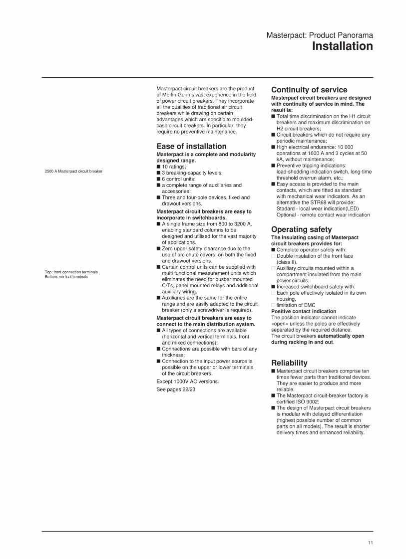
2500 A Masterpact circuit breaker
Top: front connection terminalsBottom: vertical terminals
Masterpact: Product Panorama
Installation

12
Drawout Masterpact DC circuit breaker
Fixed Masterpact DC circuit breaker
Device identificationM 20 H1
Breaking capacity; H1: H2: high performance; L1: current limiting; DC: direct current.
Rating rated current / 100.
Family Masterpact: LV power air circuit breaker.
DC circuit breakersMasterpact DC circuit breakers are availablein fixed and drawout versions. 5 available ratings from 1000 to 8000 A; 2 breaking capacities, 100 kA at 500 V,
50 kA at 750 and 1000 V; A version offering instantaneous short-
circuit protection with an adjustable,magnetic trip unit (DINA);
A switch (unprotected) version.note: up to 125 V DC, the devices in the ACrange (M08 to M63) may be used for theswitch version only, in which case a three-pole, type HI device should be used, with: 1 pole for the positive polarity; 1 pole for the negative polarity; 1 pole left unused.
AuxiliariesAll the auxiliaries designed for theMasterpact AC circuit breakers may be usedon the DC versions, with the exception of theposition switches, indicating the connected(CE), disconnected (CD) and test (CT)positions.Auxiliary connections are made via one ortwo manually disconnectable plugs thatremain accessible from the front.
AccessoriesStandard Masterpact DC range equipmentincludes an arc-chute cover (CC) and, ondrawout versions, safety shutters (VO).Interphase barriers (EIP) are not availablefor the DC range.
Masterpact: Product Panorama
DC circuit breakers

13

14
Masterpact circuit breakers and switch-disconnectorsType
Dimensions and weightsDimensions W x H x D drawout 3P(mm) 4P
fixed 3P4P
Maximum weight drawout 3P(kg) 4P
fixed 3P4P
Masterpact circuit breakers and switch-disconnectorsType
Dimensions and weightsDimensions W x H x D drawout 3P(mm) 4P
fixed 3P4P
Maximum weight drawout 3P(kg) 4P
fixed 3P4P
Masterpact 1000 V circuit breakersTypeDimensions and weightsdimensions W x H x D drawout 3P(mm) 4PMaximum weight drawout 3P(kg) 4P
Masterpact DC circuit breakersType of pole connectionsNumber of poles
Dimensions and weightsDimensions W x H x D (mm) drawout version
fixed versionWeight (kg) drawout version
fixed versionchassis only
sensor selectionIn (A) 200 250 320 400 500 600 630 800 1000 1200Ir threshold 80 100 125 160 200 240 250 320 400 480settings (A) to 200 to 250 to 320 to 400 to 500 to 600 to 630 to 800 to 1000 to 1200In (A) 1250 1600 2000 2500 3000 3200 4000 5000 6000 6300Ir threshold 500 640 800 1000 1200 1280 1600 2000 2400 2500settings (A) to 1250 to 1600 to 2000 to 2500 to 3000 to 3200 to 4000 to 5000 to 6000 to 6300
The table above indicates:
All the available sensor ratings(current transformers) In;
The limits of the long time Ir settings.* for connection details see page no 98
Masterpact: Product Panorama
Weights and dimensions

15
M08 M10 M12 M16 M20 M25 M32H1/H2/L1 H1/H2/L1 H1/H2/L1 H1/H2 L1 H1/H2 L1 H1/H2 L1 H1/H2HI/HF HI/HF HI/HF HI/HF HI/HF HI/HF HI/HF
435 x 439 x 367 435 x 439 x 367 435 x 439 x 367 435 x 439 x 367 435 x 439 x 367 435 x 439 x 367 435 x 439 x 367550 x 439 x 367 550 x 439 x 367 550 x 439 x 367 550 x 439 x 367 550 x 439 x 367 550 x 439 x 367 550 x 439 x 367422 x 356 x 290 422 x 356 x 290 422 x 356 x 290 422 x 356 x 290 422 x 356 x 290 422 x 356 x 290 422 x 356 x 290537 x 356 x 290 537 x 356 x 290 537 x 356 x 290 537 x 356 x 290 537 x 356 x 290 537 x 356 x 290 537 x 356 x 29065 65 65 69 82 82 130 82 130 13080 80 80 85 102 102 150 102 150 15043 43 43 46 55 55 80 55 80 8054 54 54 58 69 69 90 69 90 90
M40 M50 M63H1/H2 H1/H2 H1/H2HI/HF HI/HF HI/HF
550 x 439 x 367 815 x 484 x 367 1045 x 484 x 367815 x 484 x 367 1045 x 484 x 367 1045 x 484 x 367537 x 356 x 290 802 x 356 x 290801 x 356 x 290150 215 245200 230 26590 110110
M08 M10 M12 M16 M20 M25 M32H1 H1 H1 H1 H1 H1 H1
435 x 439 x 367 435 x 439 x 367 435 x 439 x 367 435 x 439 x 367 435 x 439 x 367 435 x 439 x 367 435 x 439 x 367550 x 439 x 367 550 x 439 x 367 550 x 439 x 367 550 x 439 x 367 550 x 439 x 367 550 x 439 x 367 550 x 439 x 36765 65 65 69 82 82 13080 80 80 85 102 102 15
M10DC M20DC M40DC M60DC M80DCD or H* E, F or J* D or H* E, F or J* D or H* E, F or J* G* G*3 4 3 4 3 4 2 2
435x439x536 550x439x536 435x439x536 550x439x536 435x439x641 550x439x641 550x439x484 550x439x484438x404x393 553x404x393 438x404x393 553x404x393 438x404x530 553x404x530125 160 125 160 135 170 150 15065 80 65 80 65 80 80 8080 100 80 100 90 110 90 90
Masterpact: Product Panorama
Weights and dimensions

16

17
LV air circuit breakersand switch-disconnectors
Masterpact800 to 6300 Amp
Perfomance andfunctionality
page
M08 to M16 18
M20 to M63 20
Circuit brakers for 1000V AC 22
Switch disconnectors M08 to M16 24
Switch disconnectors M20 to M63 26
Circuit brakers for DC 28
Section 2
2
18
Masterpact: Performance and functionality
Circuit breaker selection
(1) Defined for a power factor of 0.25 if 20 < kA rms≤ 50 or 0.20 of kA rms > 50.
(2) Closing at 6 x Ie and opening at 0.17 x Un.(3) For control unit STR 68 U, the minimum rating
In is 400 A.
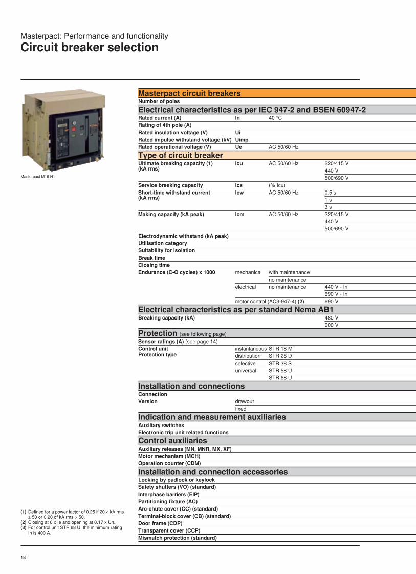
Masterpact circuit breakersNumber of poles
Electrical characteristics as per IEC 947-2 and BSEN 60947-2Rated current (A) In 40 °CRating of 4th pole (A)Rated insulation voltage (V) UiRated impulse withstand voltage (kV) UimpRated operational voltage (V) Ue AC 50/60 Hz
Type of circuit breakerUltimate breaking capacity (1) Icu AC 50/60 Hz 220/415 V(kA rms) 440 V
500/690 VService breaking capacity Ics (% Icu)Short-time withstand current Icw AC 50/60 Hz 0.5 s(kA rms) 1 s
3 sMaking capacity (kA peak) Icm AC 50/60 Hz 220/415 V
440 V500/690 V
Electrodynamic withstand (kA peak)Utilisation categorySuitability for isolationBreak timeClosing timeEndurance (C-O cycles) x 1000 mechanical with maintenance
no maintenanceelectrical no maintenance 440 V - In
690 V - Inmotor control (AC3-947-4) (2) 690 V
Electrical characteristics as per standard Nema AB1Breaking capacity (kA) 480 V
600 V
Protection (see following page)Sensor ratings (A) (see page 14)Control unit instantaneous STR 18 MProtection type distribution STR 28 D
selective STR 38 Suniversal STR 58 U
STR 68 U
Installation and connectionsConnectionVersion drawout
fixed
Indication and measurement auxiliariesAuxiliary switchesElectronic trip unit related functions
Control auxiliariesAuxiliary releases (MN, MNR, MX, XF)Motor mechanism (MCH)Operation counter (CDM)
Installation and connection accessoriesLocking by padlock or keylockSafety shutters (VO) (standard)Interphase barriers (EIP)Partitioning fixture (AC)Arc-chute cover (CC) (standard)Terminal-block cover (CB) (standard)Door frame (CDP)Transparent cover (CCP)Mismatch protection (standard)
Masterpact M16 H1

19
Masterpact: Performance and functionality
Circuit breaker selection
M08 M10 M12 M163, 4 3, 4 3, 4 3, 4
800 1000 1250 1600800 1000 1250 16001000 1000 1000 10008 8 8 8690 690 690 690
H1 H2 L1 H1 H2 L1 H1 H2 L1 H1 H2 L165 100 130 65 100 130 65 100 130 65 100 13065 100 110 65 100 110 65 100 110 65 100 11065 85 65 65 85 65 65 85 65 65 85 65100 % 100 % 100 % 100 % 100 % 100 % 100 % 100 % 100 % 100 % 100 % 100 %65 65 12 65 65 12 65 65 12 65 65 1750 50 12 50 50 12 50 50 12 50 50 1732 32 12 32 32 12 32 32 12 32 32 12143 220 286 143 220 286 143 220 286 143 220 286143 220 242 143 220 242 143 220 242 143 220 242143 187 143 143 187 143 143 187 143 143 187 143143 143 24 143 143 24 143 143 24 143 143 34B B B B B B B B B B B B
25 to 30 ms without intentional time delay and 9 ms for type L170 ms20 20 20 20 20 20 20 20 15 20 20 1510 10 10 10 10 10 10 10 10 10 10 1010 10 3 10 10 2.7 10 10 2.5 10 10 2.210 10 3 10 10 2.7 10 10 2.5 10 10 2.210 10 - 10 10 - 10 10 - 10 10 -
65 100 - 65 100 - 65 100 - 65 100 -65 65 - 65 65 - 65 65 - 65 65 -
200 to 800 (3) 200 to 1000 (3) 200 to 1250 (3) 200 to 1600 (3)
n n n
Front and rear connections

20
Masterpact circuit breakersNumber of poles
Electrical characteristics as per IEC 947-2 and BS EN 60947-2Rated current (A) In 40 °CRating of 4th pole (A)Rated insulation voltage (V) UiRated impulse withstand voltage (kV) UimpRated operational voltage (V) Ue AC 50/60 Hz
Type of circuit breakerUltimate breaking capacity (1) Icu AC 50/60 Hz 220/415 V(kA rms) 440 V
500/690 VService breaking capacity Ics (% Icu)Short-time withstand current Icw AC 50/60 Hz 0.5 s(kA rms) 1 s
3 sMaking capacity (kA peak) Icm AC 50/60 Hz 220/415 V
440 V500/690 V
Electrodynamic withstand (kA peak)Utilisation categorySuitability for isolationBreak timeClosing timeEndurance (C-O cycles) x 1000 mechanical with maintenance
no maintenanceelectrical no maintenance 440 V - In
690 V - Inmotor control (AC3-947-4) (2) 690 V
Electrical characteristics as per standard Nema AB1Breaking capacity (kA) 480 V
600 V
Protection (see following pages)Sensor ratings (A) (see page 14)Control unit instantaneous STR 18 MProtection type distribution STR 28 D
selective STR 38 Suniversal STR 58 U
STR 68 U
Installation and connectionsConnectionVersion drawout
fixed
Indication and measurement auxiliariesAuxiliary switchesElectronic trip unit related functions
Control auxiliariesAuxiliary releases (MN, MNR, MX, XF)Motor mechanism (MCH)Operation counter (CDM)
Installation and connection accessoriesLocking by padlock or keylockSafety shutters (VO) (standard)Interphase barriers (EIP)Partitioning fixture (AC)Arc-chute cover (CC) (standard)Terminal-block cover (CB) (standard)Door frame (CDP)Transparent cover (CCP)Mismatch protection (standard)
Masterpact M50 H1
(1) Defined for a power factor of 0.25 if 20 < kA rms≤ 50 or 0.20 of kA rms > 50.
(2) Closing at 6 x Ie and opening at 0.17 x Un.(3) For control unit STR 68 U, the minimum rating
In is 400 A.(4) 83% if Ue i 440 V.(5) Consult us for full rated neutral.
Masterpact: Performance and functionality
Circuit breaker selection

21
M20 M25 M32 M40 M50 M633, 4 3, 4 3, 4 3, 4 3, 4 3, 4
2000 2500 3200 4000 5000 63002000 2500 3200 4000 2500 (5) 32001000 1000 1000 1000 1000 10008 8 8 8 8 8690 690 690 690 690 690
H1 H2 L1 H1 H2 L1 H1 H2 H1 H2 H1 H2 H1 H275 100 130 75 100 130 75 100 75 100 100 150 100 15075 100 110 75 100 110 75 100 75 100 100 150 100 15075 85 65 75 85 65 75 85 75 85 85 85 85 85100 % 100 % 100 % 100 % 100 % 100 % 100 % 100 % 100 % 100 % 100 % 100 % (4) 100 % 100 % (4)75 75 17 75 75 17 75 75 75 75 100 100 100 10075 75 17 75 75 17 75 75 75 75 100 100 100 10057 57 17 75 75 17 75 75 75 75 100 100 100 100165 220 286 165 220 286 165 220 165 220 220 330 220 330165 220 242 165 220 242 165 220 165 220 220 330 220 330165 187 143 165 187 143 165 187 165 187 187 187 187 187165 165 34 165 165 34 165 165 165 165 220 220 220 220B B B B B B B B B B B B B B
25 to 30 ms without intentional time delay and 9 ms for type L170 ms 80 ms15 15 15 15 15 15 15 15 10 10 10 10 10 1010 10 10 10 10 10 10 10 5 5 5 5 5 59 9 2 8 8 1.8 4 4 3 3 3 3 2 27 7 2 6 6 1.8 2.6 2.6 2.5 2.5 2.5 2.5 1.5 1.57 7 - 6 6 - 2.6 2.6 2.5 2.5 2.5 2.5 1.5 1.5
75 100 - 75 100 - 75 100 75 100 100 125 100 15075 75 - 75 75 - 75 75 75 75 100 100 100 100
200 to 2000 (3) 300 to 2500 (3) 600 to 3200 2000 to 4000 2000 to 5000 2000 to 6300
Front and rear connections Rear connections
(3P only)
Masterpact: Performance and functionality
Circuit breaker selection

22
Masterpact: Performance and functionality
Circuit breaker selectionMasterpact 1000V AC
Masterpact 1000 V AC circuit breakersNumber of poles
Electrical characteristics as per IEC 947-2 and EN 60947-2Rated current (A) In 40 °CRating of 4th pole (A)Rated insulation voltage (V) UiRated impulse withstand voltage (kV) UimpRated operational voltage (V) Ue AC 50/60 Hz
Type of circuit breakerUltimate breaking capacity (1) Icu AC 50/60 Hz 220/415 V(kA rms) 440 V
500/690 V1000 V
Service breaking capacity Ics (% Icu)Short-time withstand current Icw AC 50/60 Hz 0.5 s(kA rms) 1 s
3 sMaking capacity (kA peak) Icm AC 50/60 Hz 220/415 V
440 V500/690 V1000 V
Electrodynamic withstand (kA peak)Utilisation categorySuitability for isolationBreak timeClosing timeEndurance (C-O cycles) x 1000 mechanical with maintenance
no maintenanceelectrical no maintenance 440 V - In
690 V - Inmotor control (AC3-947-4) (2) 690 V
Protection (see following pages)Sensor ratings (A) (see page 14)Control unit instantaneous STR 18 MProtection type distribution STR 28 D
selective STR 38 Suniversal STR 58 U
STR 68 U
Installation and connectionsConnectionVersion drawout
fixed
Indication and measurement auxiliariesAuxiliary switchesElectronic trip unit related functions
Control auxiliariesAuxiliary releases (MN, MNR, MX, XF)Motor mechanism (MCH)Operation counter (CDM)
Installation and connection accessoriesLocking by padlock or keylockSafety shutters (VO) (standard)Interphase barriers (EIP)Partitioning fixture (AC)Arc-chute cover (CC) (standard)Terminal-block cover (CB) (standard)Door frame (CDP)Transparent cover (CCP)
Mismatch protection (standard)
(1) Defined for a power factor of 0.25 if 20 < kA rms≤ 50 or 0.20 of kA rms > 50.
(2) Closing at 6 x Ie and opening at 0.17 x Un.(3) For control unit STR 68 U, the minimum rating
In is 400 A.
Masterpact M20 H1 1000 V

23
Masterpact: Performance and functionality
Circuit breaker selectionMasterpact 1000V AC
M08 M10 M12 M16 M20 M25 M323, 4 3, 4 3, 4 3, 4 3, 4 3, 4 3, 4
800 1000 1250 1600 2000 2500 3200800 1000 1250 1600 2000 2500 32001000 1000 1000 1000 1000 1000 10008 8 8 8 8 8 81000 1000 1000 1000 1000 1000 1000
H1 H1 H1 H1 H1 H1 H165 65 65 65 75 75 7565 65 65 65 75 75 7565 65 65 65 75 75 7545 45 45 45 45 45 45100 % 100 % 100 % 100 % 100 % 100 % 100 %45 45 45 45 45 45 4545 45 45 45 45 45 4532 32 32 32 45 45 4595 95 95 95 95 95 95143 143 143 143 165 165 165143 143 143 143 165 165 165143 143 143 143 165 165 165143 143 143 143 165 165 165B B B B B B B
25 to 30 ms without intentional time delay and 9 ms for type L170 ms20 20 20 20 15 15 1510 10 10 10 10 10 1010 10 10 10 9 8 410 10 10 10 7 6 2.610 10 10 10 7 6 2.6
200 to 800 (3) 200 to 1000 (3) 200 to 1250 (3) 200 to 1600 (3) 200 to 2000 (3) 300 to 2500 (3) 600 to 3200
Rear connections only / supply by upstream terminals mandatory
n

24
Masterpact: Performance and functionality
Switch-disconnectors
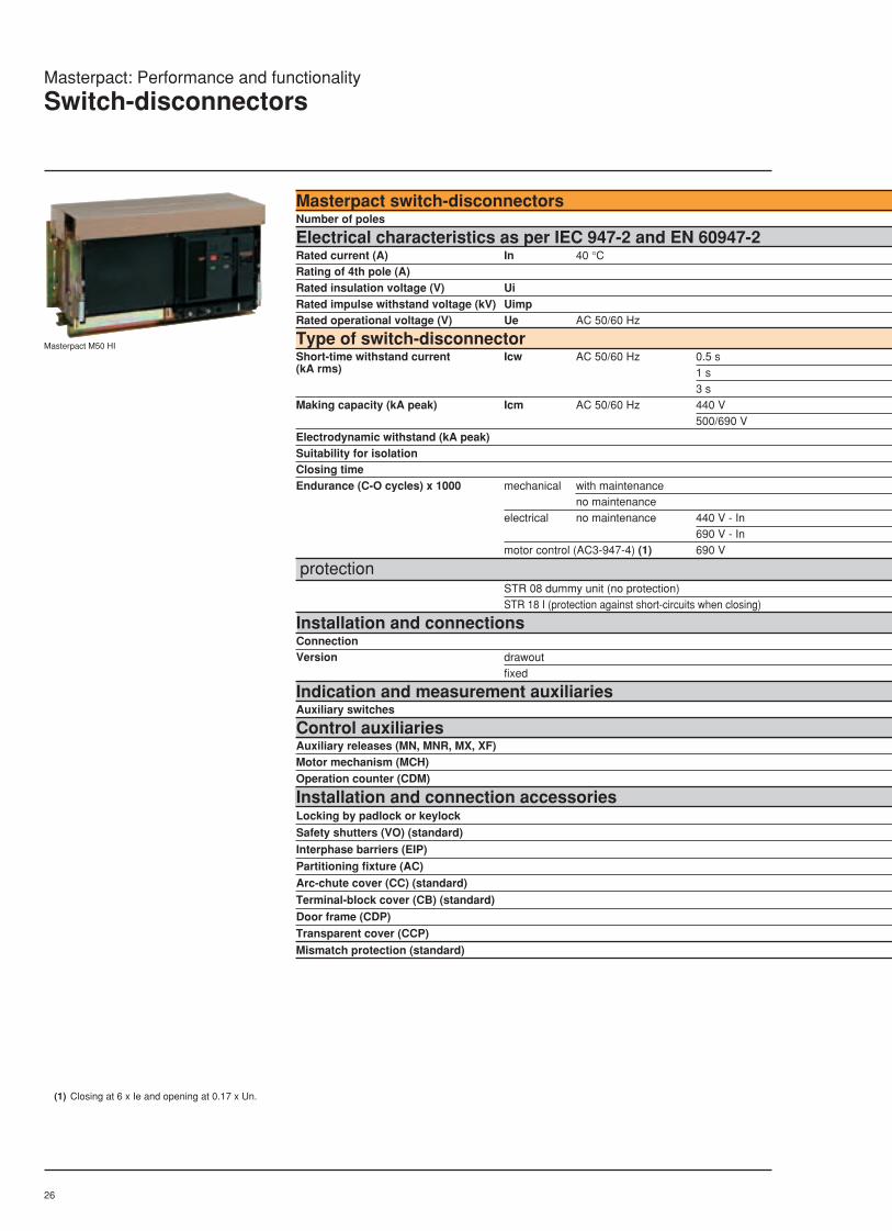
Masterpact switch-disconnectorsNumber of poles
Electrical characteristics as per IEC 947-2 and EN 60947-2Rated current (A) In 40 °CRating of 4th pole (A)Rated insulation voltage (V) UiRated impulse withstand voltage (kV) UimpRated operational voltage (V) Ue AC 50/60 Hz
Type of switch-disconnectorShort-time withstand current Icw AC 50/60 Hz 0.5 s(kA rms) 1 s
3 sMaking capacity (kA peak) Icm AC 50/60 Hz 440 V
500/690 VElectrodynamic withstand (kA peak)Suitability for isolationClosing timeEndurance (C-O cycles) x 1000 mechanical with maintenance
no maintenanceelectrical no maintenance 440 V - In
690 V - Inmotor control (AC3-947-4) (1) 690 V
ProtectionSTR 08 dummy unit (no protection)STR 18I (protection against short-circuits when closing)
Installation and connectionsConnectionVersion drawout
fixed
Indication and measurement auxiliariesAuxiliary switches
Control auxiliariesAuxiliary releases (MN, MNR, MX, XF)Motor mechanism (MCH)Operation counter (CDM)
Installation and connection accessoriesLocking by padlock or keylock
Safety shutters (VO) (standard)
Interphase barriers (EIP)
Partitioning fixture (AC)
Arc-chute cover (CC) (standard)
Terminal-block cover (CB) (standard)
Door frame (CDP)
Transparent cover (CCP)
Mismatch protection (standard)
Masterpact M10
(1) Closing at 6 x Ie and opening at 0.17 x Un.

25
Masterpact: Performance and functionality
Switch-disconnectors
M08 M10 M12 M163, 4 3, 4 3, 4 3, 4
800 1000 1250 1600800 1000 1250 16001000 1000 1000 10008 8 8 8690 690 690 690
HI HF HI HF HI HF HI HF65 65 65 65 65 65 65 6550 50 50 50 50 50 50 5032 32 32 32 32 32 32 32105 143 105 143 105 143 105 143105 143 105 143 105 143 105 143143 143 143 143 143 143 143 143
70 ms20 20 20 20 20 20 20 2010 10 10 10 10 10 10 1010 10 10 10 10 10 10 1010 10 10 10 10 10 10 1010 10 10 10 10 10 10 10
Front and rear connections
26
Masterpact: Performance and functionality
Switch-disconnectors
Masterpact switch-disconnectorsNumber of poles
Electrical characteristics as per IEC 947-2 and EN 60947-2Rated current (A) In 40 °CRating of 4th pole (A)Rated insulation voltage (V) UiRated impulse withstand voltage (kV) UimpRated operational voltage (V) Ue AC 50/60 Hz
Type of switch-disconnectorShort-time withstand current Icw AC 50/60 Hz 0.5 s(kA rms) 1 s
3 sMaking capacity (kA peak) Icm AC 50/60 Hz 440 V
500/690 VElectrodynamic withstand (kA peak)Suitability for isolationClosing timeEndurance (C-O cycles) x 1000 mechanical with maintenance
no maintenanceelectrical no maintenance 440 V - In
690 V - Inmotor control (AC3-947-4) (1) 690 V
protectionSTR 08 dummy unit (no protection)STR 18 I (protection against short-circuits when closing)
Installation and connectionsConnectionVersion drawout
fixed
Indication and measurement auxiliariesAuxiliary switches
Control auxiliariesAuxiliary releases (MN, MNR, MX, XF)Motor mechanism (MCH)Operation counter (CDM)
Installation and connection accessoriesLocking by padlock or keylock
Safety shutters (VO) (standard)
Interphase barriers (EIP)
Partitioning fixture (AC)
Arc-chute cover (CC) (standard)
Terminal-block cover (CB) (standard)
Door frame (CDP)Transparent cover (CCP)
Mismatch protection (standard)
Masterpact M50 HI
(1) Closing at 6 x Ie and opening at 0.17 x Un.

27
Masterpact: Performance and functionality
Switch-disconnectors
M20 M25 M32 M40 M50 M633, 4 3, 4 3, 4 3, 4 3, 4 3, 4
2000 2500 3200 4000 5000 63002000 2500 3200 4000 2500 32001000 1000 1000 1000 1000 10008 8 8 8 8 8690 690 690 690 690 690
HI HF HI HF HI HF HI HF HI HF HI HF75 75 75 75 75 75 75 75 100 100 100 10075 75 75 75 75 75 75 75 100 100 100 10057 57 75 75 75 75 75 75 100 100 100 100105 165 105 165 105 165 105 165 187 220 187 220105 165 105 165 105 165 105 165 187 220 187 220121 165 121 165 165 165 165 165 220 220 220 220
70 ms 80 ms15 15 15 15 15 15 10 10 10 10 10 1010 10 10 10 10 10 10 5 5 5 5 5 59 9 8 8 4 4 3 3 3 3 2 27 7 6 6 2.6 2.6 2.5 2.5 2.5 2.5 1.5 1.57 7 6 6 2.6 2.6 2.5 2.5 2.5 2.5 1.5 1.5
Front and rear connections Rear connections
(3P only)

28
Masterpact: Performance and functionality
DC circuit breaker selection
The DC range is available in two versions:c Switch (unprotected) version with
(STR08I);c Circuit-breaker version with instantaneous
short-circuit protection with an adjustable,magnetic trip unit (DINA).
note: for voltages up to 125 V DC, thedevices in the AC range (M08 to M63) maybe used only in the switch version, inwhich case a three-pole type HI deviceshould be used, with:c 1 pole for the positive polarity;c 1 pole for the negative polarity;c 1 pole unused.
(1) Type H : only suitable for 3600 A for an ambient temperature of 40 °C.(2) Type J : only suitable for 3500 A for an ambient temperature of 40 °C.
Optional Standard* for connection details see page 98
Masterpact DC circuit breakersType of pole connectionsNumber of poles
Electrical characteristics as defined by IEC 947-2 and EN 60947-2Rated operational voltage (V DC) UeRated current (A) In 40 °CRated insulation voltage (V) UiRated impulse withstand voltage (kV) UimpUltimate breaking capacity (kA rms) Icu L/R i 15 msService breaking capacity Ics (% Icu)Suitability for isolationUtilisation categoryShort-time withstand current Icw (kA rms, 1 s)Endurance (C-O cycles) mechanical no maintenance
with maintenanceelectrical (at Ue) no maintenance
Operating time total max breakingclosing
ProtectionAdjustable magnetic trip unit (DINA)Switch (unprotected) version (STR08I)
Installation and connectionsFixed rear connectionDrawout rear connection
Indication and measurement auxiliariesAuxiliary switches (O, OF, OFSUP)"Ready to close" contact (PF)"Spring charged" contact (CH)Fault trip indication (SDE)Connected/disconnected/test position switches (CE, CD, CT)Electronic trip-unit functions
Control auxiliariesAuxiliary releases (MN, MNR, MX, XF)Motor mechanism (MCH)Operation counter (CDM)
Installation and connection accessoriesLocking by padlock or keylockSafety shutters (VO)Arc-chute cover (CC)Terminal-block cover (CB)Interphase barriers (EIP)Partitioning fixture (AC)Door frame (CDP)Transparent cover (CCP)Mismatch protection
Dimensions and weightsDimensions W x H x D (mm) drawout version
fixed versionWeight (kg) drawout version
fixed versionchassis only

29
Masterpact: Performance and functionality
DC circuit breaker selection
M10DC M20DC M40DC M60DC M80DCD or H* E, F or J* D or H* E, F or J* D or H* E, F or J* G* G* 3 4 3 4 3 4 2 2
250/500 750/1000 250/500 750/1000 250/500 750/1000 250 2501000 1000 2000 2000 4000 (1) 4000 (2) 6000 80001000 1000 1000 1000 1000 1000 1000 10008 8 8 8 8 8 8 8100 50 100 50 100 50 100 100100% 100% 100% 100% 100% 100% 100% 100%v v v v v v v vB B B B B B B B100 50 100 50 100 50 100 10010 000 10 000 10 000 10 000 5000 5000 5000 500015 000 15 000 15 000 15 000 10 000 10 000 10 000 10 00010 000 1600 8500 1600 4000 1600 1600 160030 to 75 ms60 ms
435x439x536 550x439x536 435x439x536 550x439x536 435x439x641 550x439x641 550x439x484 550x439x484438x404x393 553x404x393 438x404x393 553x404x393 438x404x530 553x404x530125 160 125 160 135 170 150 15065 80 65 80 65 80 80 8080 100 80 100 90 110 90 90
30
31
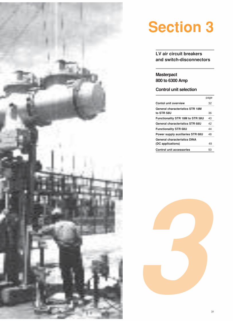
LV air circuit breakersand switch-disconnectors
Masterpact800 to 6300 Amp
Control unit selection
page
Contol unit overview 32
General characteristics STR 18Mto STR 58U 36
Functionality STR 18M to STR 58U 40
General characteristics STR 68U 42
Functionality STR 68U 44
Power supply auxiliaries STR 68U 48
General characteristics DINA(DC applications) 49
Control unit accessories 50
Section 3
3
32
push to reset
STR 18 M
I
xIn
test
+ –
1
812 14
19
22max2
4
2
5
3
4
5
push to reset
II1 I2 I3
90%
50%
20%
STR 58 U
τ tr
Ir fault
tr
Im faulttm
I
faultIh
th
t
i
test
+ –
– +
T
R
Ftest
Ir :
Im :
th :
Max.
norm
overcurrent
ground
2
3
4
5
21
6
7
8
21
16
V
reset V II+T L+I
L+I+T
ToffL
L+T
xIn
Io
0.5
0.63 0.8
1
90
105%Ir
.88.9 .92
.95
.981.8
.85
Ir
xIo
60120 240
48015
30
tr
at 1.5IrIm tm
xIr on I2t off
34 5
6
8101.5
2
.3.4 .3
.2
.10.1
.2
I
xInoff
2219
141284
2
Ih 1200A Max th
A on I2t off
400500 600
800
10001200250
320
.3.4 .4
.3
.2.1.1
.2
Ic1 Ic2
xIr
.86.9 .93
.95
.9818
.85
.7.8 .85
.9
.951.5
.6
xIr
1
12
9
10
11
13
15
14
17
19
24 18
2023
22
push to reset
II1 I2 I3
90%
50%
20%
STR 28 D
Io
xIn
90
105%Ir
xIoIm
xIr
Ir
Im
t
i
test
+ –
Ir :
Im :
Ir
1
.88.9 .92
.95
.981.8
.850.5
0.63 0.8
1
34 5
6
8101.5
2
2
3
4
115
6
7
9
8
10
11
push to reset
II1 I2 I3
90%
50%
20%
STR 38 S
xIn xIoIm tm
xIr on I2t off
Ir fault
tr
Im faulttm
I
faultIh
th
t
i
test
+ –
– +
T
Ftest
Ih th
A on I2t off
I
xIn
Ir :
Im :
th :
overcurrent
ground
1
2
3
4
1690
105%Ir
Io
0.5
0.63 0.8
1
Ir
.88.9 .92
.95
.981.8
.85
34 5
6
8101.5
2
.3.4 .3
.2
.10.1
.2
max. off
400500 600
800
10001200250
320
.3.4 .4
.3
.2.1.1
.2
5
6
7
8 9
12
11
1314
16 15
1918
17
10
Masterpact: Control unit selection
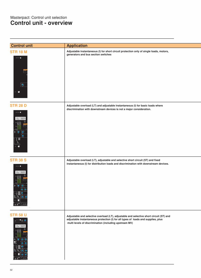
Control unit - overview
Control unit Application
STR 18 M
STR 28 D
STR 38 S
STR 58 U
Adjustable instantaneous (I) for short circuit protection only of single loads, motors,generators and bus section switches
Adjustable overload (LT) and adjustable instantaneous (I) for basic loads wherediscrimination with downstream devices is not a major consideration.
Adjustable overload (LT), adjustable and selective short circuit (ST) and fixedinstantaneous (I) for distribution loads and discrimination with downstream devices.
Adjustable and selective overload (LT), adjustable and selective short circuit (ST) andadjustable instantaneous protection (I) for all types of loads and supplies, plus multi levels of discrimination (including upstream MV)
33
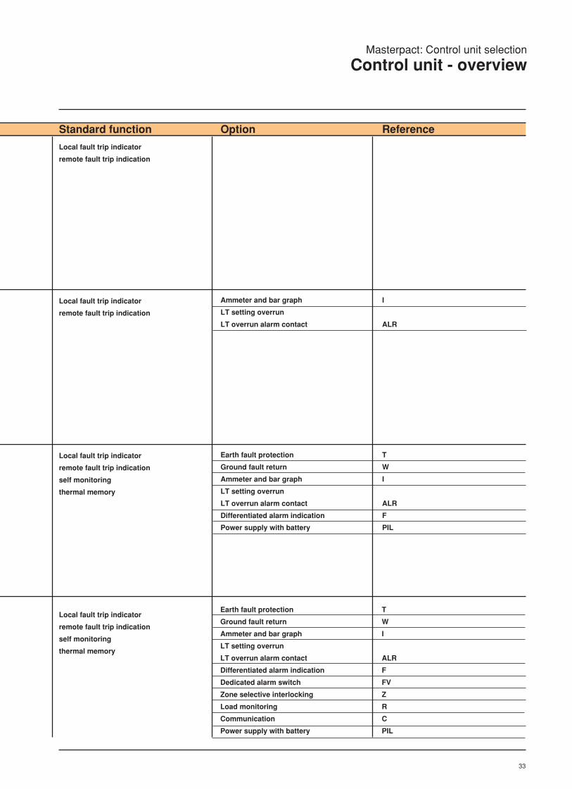
Masterpact: Control unit selection
Control unit - overview
Local fault trip indicator
remote fault trip indication
Local fault trip indicator
remote fault trip indication
I
ALR
Ammeter and bar graph
LT setting overrun
LT overrun alarm contact
Local fault trip indicator
remote fault trip indication
self monitoring
thermal memory
Local fault trip indicator
remote fault trip indication
self monitoring
thermal memory
T
W
I
ALR
F
PIL
Earth fault protection
Ground fault return
Ammeter and bar graph
LT setting overrun
LT overrun alarm contact
Differentiated alarm indication
Power supply with battery
T
W
I
ALR
F
FV
Z
R
C
PIL
Earth fault protection
Ground fault return
Ammeter and bar graph
LT setting overrun
LT overrun alarm contact
Differentiated alarm indication
Dedicated alarm switch
Zone selective interlocking
Load monitoring
Communication
Power supply with battery
Standard function Option Reference

34
Masterpact: Control unit selection
Control unit - overview
Control unit Application
STR 18 M Key pad operation and LCD display of:Adjustable and selective overload (LT), adjustable and selective short circuit (ST) andAdjustable instantaneous protection (I) for all types of loads and complex levels ofDiscrimination (including upstream MV)
STR 68 U
STR 68 U
reset
1 2 3 max
A
Ir Im I
s
Ih
tmth
fault
adjustments
24 V DC
test
KA
S
1
tr
A
trip no trip MEM
test
2%
load monitoringmaintenance
N 1 2 3
Hz
Cos ϕ
kW
MWh
+–
685812
V
10
88
9
7
611
5
4
3
2
2
1

35
Masterpact: Control unit selection
Control unit - overview
All STR58U but includes localdifferentiated fault trip indication andlevel
Remote fault trip indication
Local pre-alarm indication
Maintenance indicator
Self monitoring
Ammeter
Integral test function
Thermal memory
T
W
(Consult us)
(Consult us)
P
Earth fault protection
Earth fault protection
Load monitoring outputs
Remote indication outputs
Power measurement display
Data transmission (Consult us)
Standard function Option Reference

36
Masterpact: Control unit selection
General characteristics - STR18M to STR58U
16080 1250 2000 2500 4000 6300500032001600
STR 18 M
STR 28 D
STR 38 S
STR 58 U
STR 68 U
Masterpact M08 to M63 circuit breakers areequipped with microprocessor-basedelectronic control units.
All the protection functions are powered bythe AC system and under normal conditionsno auxiliary power supply is required*.
Each control unit of the Masterpact rangecorresponds to a certain type of application(instantaneous, distribution, selective,universal).All the STR control units measure the truerms value of the current and are thereforenot affected by harmonics that may bepresent on the system.
*see AD module page no 50 and note 4page 40
Current settings (A)
ProtectionSTR 18 M
3
I I
t
0
push to reset
STR 18 M
I
xIn
test
+ –
1
812 14
19
22max2
4
2
5
3
4
5
Key:
1 Reset button: indicates when the circuitbreaker has tripped on a fault and mustbe pressed (reset) before the circuitbreaker can be closed again.
2 Maximum protection rating.
3 Instantaneous pick-up.
4 Test connector.
5 Provision for sealable cover platescrews.
Instantaneous protection
Distribution protection
Selective protection
Universal protection

37
ProtectionSTR 28 DKey:
1 Reset button: indicates when the circuitbreaker has tripped on a fault and mustbe pressed (reset) before the circuitbreaker can be closed again.
2 Ammeter digital display.
3 Bar graph indicating load level (% Ir).
4 Maximum protection rating.
5-6 Long-time current setting as a functionof: Io x Ir x In.
7 Instantaneous pick-up.
8 Overcurrent indicator LED.
9 Noted settings.
10 Test connector.
11 Provision for sealable cover plate
screws.
push to reset
II1 I2 I3
90%
50%
20%
STR 28 D
Io
xIn
90
105%Ir
xIoIm
xIr
Ir
Im
t
i
test
+ –
Ir :
Im :
Ir
1
.88.9 .92
.95
.981.8
.850.5
0.63 0.8
1
34 5
6
8101.5
2
2
3
4
115
6
7
9
8
10
11
ProtectionSTR 38 SKey:
1 Reset button: indicates when the circuit breaker has tripped on a fault and mustbe pressed (reset) before the circuitbreaker can be closed again.
2 Ammeter digital display.
3 Bar graph indicating load level (% Ir).
4 Maximum protection rating.
5 Overcurrent indicator LED.
6-7 Long-time current setting as a functionof: Io x Ir x In.
8 Short-time pick-up.
9 Short-time delay.
10 Noted settings.
11 Instantaneous pick-up.
12 Earth fault pick-up.
13 Earth fault delay.
14 LEDs indicating tripping on long-time,short-time or earth fault.
15 Test connector.
16 Provision for sealable cover platescrews.
17 Battery supplying backup power forfault indication.
18 Fault indication reset and/or batterytest.
19 Re-indication of last fault.
push to reset
II1 I2 I3
90%
50%
20%
STR 38 S
xIn xIoIm tm
xIr on I2t off
Ir fault
tr
Im faulttm
I
faultIh
th
t
i
test
+ –
– +
T
Ftest
Ih th
A on I2t off
I
xIn
Ir :
Im :
th :
overcurrent
ground
1
2
3
4
1690
105%Ir
Io
0.5
0.63 0.8
1
Ir
.88.9 .92
.95
.981.8
.85
34 5
6
8101.5
2
.3.4 .3
.2
.10.1
.2
max. off
400500 600
800
10001200250
320
.3.4 .4
.3
.2.1.1
.2
5
6
7
8 9
12
11
1314
16 15
1918
17
10
7
6
I IIr
t
0
Other functionsc Fault indication;c Ammeter.
11
Ir Im
8
I I
t
0
7
912
13
I2t ON
I2t OFF
Other functions Fault indication; Ammeter; Indication of type of fault (F).
Masterpact: Control unit selection
General characteristics - STR18M to STR58U

38
ProtectionSTR 58 U
push to reset
II1 I2 I3
90%
50%
20%
STR 58 U
τ tr
Ir fault
tr
Im faulttm
I
faultIh
th
t
i
test
+ –
– +
T
R
Ftest
Ir :
Im :
th :
Max.
norm
overcurrent
ground
2
3
4
5
21
6
7
8
21
16
V
reset V II+T L+I
L+I+T
ToffL
L+T
xIn
Io
0.5
0.63 0.8
1
90
105%Ir
.88.9 .92
.95
.981.8
.85
Ir
xIo
60120 240
48015
30
tr
at 1.5IrIm tm
xIr on I2t off
34 5
6
8101.5
2
.3.4 .3
.2
.10.1
.2
I
xInoff
2219
141284
2
Ih 1200A Max th
A on I2t off
400500 600
800
10001200250
320
.3.4 .4
.3
.2.1.1
.2
Ic1 Ic2
xIr
.86.9 .93
.95
.9818
.85
.7.8 .85
.9
.951.5
.6
xIr
1
12
9
10
11
13
15
14
17
19
24 18
2023
22
Other functions Fault indication;
Ammeter;
Self-monitoring;
Fault type indication (F);
Segregated alarm switch for selectedfault type (V);
Zone selective interlocking (Z); Load monitoring (R);
Communication (COM).
9
13
Ir Im
10
I I
t
0
8
1114
15
I2t ON
I2t OFF
Key:
1 Reset button: indicates when the circuitbreaker has tripped on a fault and mustbe pressed (reset) before the circuitbreaker can be closed again.
2 Selection of fault type for segregatedalarm: Ir and/or Im and/or Ih
L: long-time fault (Ir)
I: short-time fault (Im/l)
T: earth fault (Ih)
3 Ammeter digital display.
4 Bar graph indicating load level (% Ir).
5 Maximum protection rating.
6 Overcurrent indicator LED.
7-8 Long-time current setting as a functionof: Io x Ir x In.
9 Long-time trip delay
10 Short-time pick-up.
11 Short-time delay.
12 Adjustment of thermal memory aftertripping.
13 Anstantaneous pick-up.
14 Earth fault pick-up.
15 Eearth fault delay.
16 Noted settings.
17-18 Load monitoring settings.
19 Test connector.
20 Battery supplying backup power for faultindication.
21 Provision for sealable cover platescrews.
22 Fault indication reset and/or battery test.
23 Re-indication of last fault.
24 LEDs indicating tripping on long-time,short-time or earth fault.
Masterpact: Control unit selection
General characteristics - STR18M to STR58U
39
I
t
0
Ih
Th
I2t ON
I2t OFF
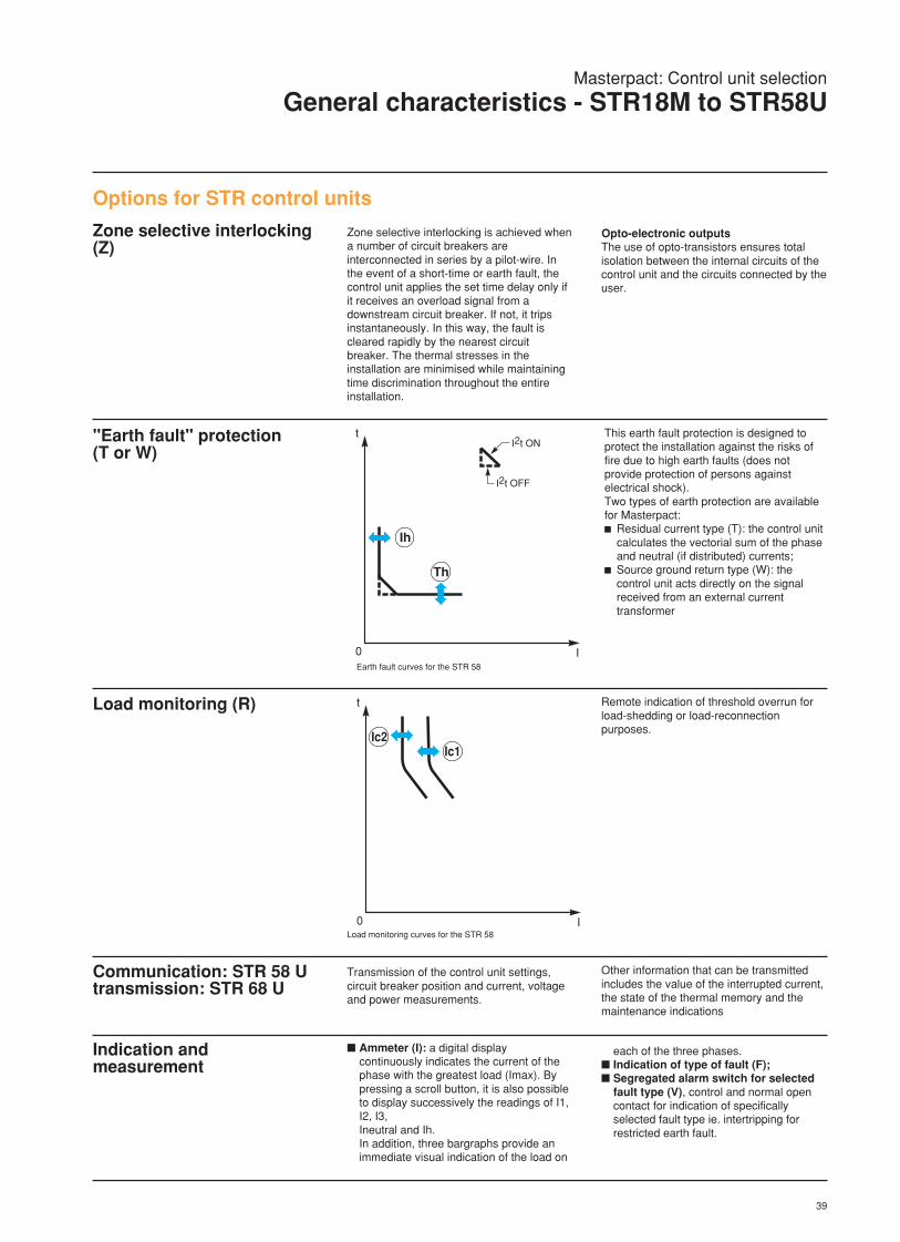
Options for STR control units
Zone selective interlocking(Z)
"Earth fault" protection(T or W)
This earth fault protection is designed toprotect the installation against the risks offire due to high earth faults (does notprovide protection of persons againstelectrical shock).Two types of earth protection are availablefor Masterpact:c Residual current type (T): the control unit
calculates the vectorial sum of the phaseand neutral (if distributed) currents;
c Source ground return type (W): thecontrol unit acts directly on the signalreceived from an external currenttransformer
Earth fault curves for the STR 58
Load monitoring (R) Remote indication of threshold overrun forload-shedding or load-reconnectionpurposes.
I
t
0
Ic2Ic1
Load monitoring curves for the STR 58
Communication: STR 58 Utransmission: STR 68 U
Transmission of the control unit settings,circuit breaker position and current, voltageand power measurements.
Indication andmeasurement
Ammeter (I): a digital displaycontinuously indicates the current of thephase with the greatest load (Imax). Bypressing a scroll button, it is also possibleto display successively the readings of I1,I2, I3,Ineutral and Ih.In addition, three bargraphs provide animmediate visual indication of the load on
Zone selective interlocking is achieved whena number of circuit breakers areinterconnected in series by a pilot-wire. Inthe event of a short-time or earth fault, thecontrol unit applies the set time delay only ifit receives an overload signal from adownstream circuit breaker. If not, it tripsinstantaneously. In this way, the fault iscleared rapidly by the nearest circuitbreaker. The thermal stresses in theinstallation are minimised while maintainingtime discrimination throughout the entireinstallation.
Opto-electronic outputsThe use of opto-transistors ensures totalisolation between the internal circuits of thecontrol unit and the circuits connected by theuser.
Other information that can be transmittedincludes the value of the interrupted current,the state of the thermal memory and themaintenance indications
each of the three phases. Indication of type of fault (F); Segregated alarm switch for selected
fault type (V), control and normal opencontact for indication of specificallyselected fault type ie. intertripping forrestricted earth fault.
Masterpact: Control unit selection
General characteristics - STR18M to STR58U

40
Control unitType of circuit breaker
Basic protectionLong time protection LT
current setting (Ir) as a function of Io and Ir Io = In x ...settings tripping between 1.05 and 1.20 x Ir Ir = Io x ...time delay (tr)accuracy: + 0 - 20 % tr at 1.5 Ir (s)
tr at 6 Ir (s)tr at 7.2 Ir (s)
Short-time protection STpick-up (Im) adjustable by Im setting Im = Ir x ...time delay (tm) tm setting with I2t OFF
tm setting with I2t ONmax. overcurrent time before tripping (ms)max. break time (ms)
Instantaneous protection Ipick-up settingsetting rangeaccuracyOFF switch on front face
Basic functionsFault indication
for tripping on a fault indicator button on front facefault trip alarm contact (SDE)
for LT setting overrun (optional) LED (continuous at 0.9 Ir and flashing at 1.05 Ir)LT overrun alarm contact self-powered
Self-monitoring internal overheating
Optional functionsAmmeter (I) display between 0.2 and 1.20 In
current readings with an accuracy of ± 1.5 % (1) (3)bargraph indication of current levels with a resolution of 10 %self-powered
Earth fault protection: residual current (T) or source ground return (W) type on requestpick-up adjustable by Ih setting Ih = In x ...time delay (th) th setting with I2t ON and I2t OFF
max. overcurrent time before tripping (ms)max. break time (ms)
Indication of type of fault (F) (LT - ST/Inst. - Earth) by LEDs on front facepower supply with battery module
with external power supply by AD moduleSegregated alarm switch for selected fault type (V) (LT - ST/Inst. - Earth)
output via relay contactpower supply by AD module
Zone selective interlocking (Z)by opto-electronic contact on ST and earth (T/W) fault
Load monitoring (R)adjustment of load limit thresholds by Ic1 and Ic2 settings Ic1 = Ir x ... / Ic2 = Ir x ...time delay tr1 at 1.5 Ic1time delay tr2 at 1.5 Ic2output via opto-electronic contact 0.1 A / 240 Vtime delay for load reconnection
Communication (COM)2 outputs for data transmission to Dialpact moduletransmitted values all control unit settings
alarms: Ir warning, fault type, self-monitoringload monitoring thresholdscurrent values I1, I2, I3, IN
Power supply by AD module
(1) Plus the tolerance of the built-in transformers:
± 3 %.
(2) Max = In x ... H1 H2 L1630 A 22 28 14800 - 1000 A 22 28 101200 - 1600 A 22 24 82000 A 17 20 62500 A 12 14 63000 - 3200 A 10 12 –4000 - 6300 A 8 10 –
(3) Continuous display for the phase with thegreatest load.
(4) 0.2 x In to 1200 A without external powersupply or 0.1 x In with external power supply.
(5) Accuracy with respect to the long time LTprotection.
STR 58 U
Masterpact: Control unit selection
Functionality - STR18M to STR58U

41
Masterpact: Control unit selection
Functionality - STR18M to STR58U
STR 18 M STR 28 D STR 38 S STR 58 UH1, H2 H1, H2 H1, H2, L1 H1, H2, L1
0.5 to 1 (4 settings) 0.5 to 1 (4 settings) 0.5 to 1 (4 settings)0.8 to 1 (8 settings) 0.8 to 1 (8 settings) 0.8 to 1 (8 settings)fixed fixed adjustable120 120 15 30 60 120 240 4807.5 7.5 0.94 1.88 3.75 7.50 15 305.2 5.2 0.65 1.30 2.60 5.20 10 21
1.5 to 10 ± 15 % 1.5 to 10 ± 15 %0 0.1 0.2 0.3 0.4 0 0.1 0.2 0.3 0.4
0.1 0.2 0.3 0.1 0.2 0.30 80 140 230 350 0 80 140 230 35080 140 230 350 500 80 140 230 350 500
Im = In x ... Im = Ir x ... I = In x ... I = In x ...2 x In to Max (2) 1.5 to 10 x Ir fixed at high set (Max) (2) 2 x In to Max (2)± 15 % ± 15 % ± 20 % ± 15 %on type H1 on type H1 on types H1
I1, I2, I3, IN I1, I2, I3, IN, Ih I1, I2, I3, IN, IhI1, I2, I3 I1, I2, I3 I1, I2, I3
0.1 to 1 (max 1200 A) (4) ± 15 % 0.1 to 1 (max 1200 A) (4) ± 15 %0.1 0.2 0.3 0.4 0.1 0.2 0.3 0.460 140 230 350 60 140 230 350140 230 350 500 140 230 350 500
0.8 to 1 (8 settings) ± 1 % (5)0.5 x tr0.25 x tr
fixed at 10 s

42
The STR 68 U control unit offersmeasurement, supervision and energymanagement functions.Microprocessor technology, liquid crystaldisplay and function keys ensure highaccuracy and easy adjustment.The standard STR 68 U control unit providesthe following: Universal protection; Ammeter function; Indication of fault type; Values of interrupted currents; Maintenance indicator; Integrated test.
The following options can be added: Power measurement module (P); "Earth fault" protection module; Control and indication modules (M) with or
without transmission capabilities.Certain M modules can provide loadmonitoring or zone selective interlocking forearth fault protection.
The STR 68 control unit provides: Overload protection, with long time
protection LT which includes: Adjustable time delay and selectable
thermal memory. Short-circuit protection: Delayed, with short time function ST, for
which the I2t curve can be selected(on/off) by the user,
Adjustable instantaneous, can be selected(on/off) by the user for HI units only.
Protection "Earth" protection with time
discrimination or zone selectiveinterlocking. The protection is of theresidual current type as standard (orsource ground return type on request).
Additional functions Ammeter; Maintenance indicator; Fault indications and values of the
interrupted currents; Self-monitoring: in the event of
overheating of the control unit or amalfunction of the microprocessor, analarm signal is transmitted. and the circuitbreaker is tripped. To prevent automaticopening a service continuity option can beordered.
Test function.
Masterpact: Control unit selection
General characteristics - STR68U

43
Optional functions Power measurement (P); Indication and control (M)Thirty-one different modules offer variouscombinations of functions including: Load monitoring, Trip indication, Self-monitoring, Zone selective interlocking for "earth fault"
protection, Transmission of data to a supervisor
(SCADA)(modules M17 to M31 only).
Each STR 68 U control unit can be equippedwith only one M module.For the function offered by each M module,(see page 42).
"Earth fault" protection (T)Of the residual current type (or sourceground return type on request), it ispossible to obtain zone selectiveinterlocking by combining the T optionwith the appropriate M option.
Masterpact: Control unit selection
General characteristics - STR68U
ProtectionSTR 68 U
STR 68 U
reset
1 2 3 max
A
Ir Im I
s
Ih
tmth
fault
adjustments
24 V DC
test
KA
S
1
tr
A
trip no trip MEM
test
2%
load monitoringmaintenance
N 1 2 3
Hz
Cos ϕ
kW
MWh
+–
685812
V
10
88
9
7
611
5
4
3
2
2
1 Key:
1 Reset button: indicates when the circuitbreaker has tripped on a fault and mustbe pressed (reset) before the circuitbreaker can be closed again.
2 Selection of displayed value (voltage,power, energy, power factor, frequency).
3 Display of current or interrupted current(when flashing).
4 Local fault indication and indicationreset.
5 Selection and indication of protectionsettings.
6 Selection and indication of loadmonitoring settings.
7 Adjustment and saving of parametersettings.
8 Fittings for sealable cover plate screws.
9 Test connector.
10 Test.
11 Maintenance indicator.
Ir Im I I
t
0
LT setting(Ir)
ST pick-up(Im)
ST time delay(tm)
LT time delay(tr)
instantaneouspick-up (I)
earth fault time delay (th)
earth faultpick-up (Ih)
other functions Fault indications with memory;
Maintenance indicator;
Ammeter;
Integrated test;
Power measurement;
Load monitoring (R);
Self-monitoring;
Zone selective interlocking for earthfaults.
I2t ON

44
Control unit STR 68 UType of circuit breaker H1. H2. L1
Basic protectionLong time protection LT
current setting (Ir) adjustable in 2 % steps Ir = In x ... 0.4 to 1 (mini 160 A)tripping between 1.05 and 1.20 x Irtime delay (tr) adjustableaccuracy: + 0 - 20 % tr at 1.5 Ir (s) 15 30 60 120 240 480
tr at 6 Ir (s) 0.94 1.88 3.75 7.50 15 30tr at 7.2 Ir (s) 0.65 1.30 2.60 5.20 10 21
thermal memory (60 mn) standard + OFF positionShort time protection ST
pick-up (Im) adjustable in 4 % steps Im = Ir x ... 0.4 to 15 ± 10 %time delay (tr) tm setting with I2t OFF 0.1 0.2 0.3 0.4
tm setting with I2t ON 0.1 0.2 0.3 0.4max. overcurrent time before tripping (ms) 60 140 230 350max. break time (ms) 140 230 350 500
thermal memory (10 mn) standard + OFF positionInstantaneous protection I
fixed pick-up I (kA) M08 to M16 : 65. M20 to M63: 75.pick-up (I) adjustable in 8 % steps from In to fixed pick-up (mini at 1.6 kA)accuracy ± 15 %OFF switch on front face on type H1
Basic functionsFault indication
for tripping on a fault button on front face
fault trip alarm contact (SDE)
for Ir setting overrun LED on front face
self powered
indication of fault type LEDs on front face and value of interrupted current display on ammeter
power supply 110 V - 220 V - 380 V AC 50/60 HzSelf-monitoring internal overheating and microprocessor errors
Maintenance indicator
displays degree of wear of main contacts between 0 and 655Ammeter
current readings with an accuracy of ± 3 % I1. I2. I3. Imaxself-powered
Integrated test
Masterpact: Control unit selection
Functionality - STR68U

45
Optional functionsEarth fault protection: residual current (T) or source ground return (W) type on request c (zone selective interlocking with option M)
pick-up (Ih) adjustable in 2 % steps Ih = In x ... 0.2 to 1 (maxi 1200 A. mini 160 A ) ± 15 %time delay (th) th setting 0.1 0.2 0.3 0.4
max. overcurrent time before tripping (ms) 60 140 230 350max. break time (ms) 140 230 350 500
thermal memory (60 s)
Power measurement (P) (see opposite page for details)
output characteristics opto-decoupled 0.2 A - 24 V DCintegrated power supply
voltage measurements U12. U23. U31 160 to 690 ± 1 %V1N. V2N. V3N 90 to 400 V ± 1 %
frequency measurement: f 45 to 65 Hz ± 0.5 %power factor measurement: cos ϕ - 1 to + 1 ± 2.5 %instantaneous active power measurement: P - 9 to 9000 kW ± 5 %instantaneous active energy measurement: EP 0 to 9999 MWh ± 5 %
Indication and control (M): 31 modules (1 per control unit) providing the following combinations:
Load monitoring 2 possible optionsoption 1: 2 load limit pick-ups Ic1 and Ic2 Ic1 = In x ... 0.2 to 1 In 2 % steps
delay tr1 = 0.5 x tr ± 5 %Ic2 = In x ... 0.2 to 1 In 2 % stepsdelay tr2 = 0.25 x tr ± 5 %
option 2: 1 load limit pick-up Ic1 Ic1 = In x ... 0.2 to 1 In 2 % steps1 load reconnection pick-up Ic2 delay tr1 = 0.5 x tr ± 5 %
Ic2 = In x ... 0.2 to 1 In 2 % stepsdelay tr2 = 60 s fixed ± 5 %
Zone selective interlocking for earth fault protectionTrip indications
for type of fault long-time, short-time, earthfor self-monitoring (1) alarm
Transmissioncharacteristics type RS 485
protocol JBusspeed 4800 or 9600 baudsmax. number of addresses 255
values transmitted: type of fault tripping on Im, Ir, Ihcircuit breaker status self-monitoring alarm
settings all pick-ups and delayscircuit breaker status open or closed
values transmitted: ammeter currents I1, I2, I3 maxpower system status voltmeter voltages U12, U23, U31
voltages V1N, V2N, V3Npower factor, frequency cos ϕ, finstantaneous active power and energy: P. EP - 9 to 9000 kW. 0 to 9999 MWh ± 5 %instantaneous reactive power and energy: Q. EQ - 9 to 9000 kVar. 0 to 9999 MVahr ± 5 %
Power supply 24, 48, 125 V DC or 100, 240 V AC
(1) Depending on the equipment, the "self-monitoring" alarm signal may or may not trip the circuit breaker, see "service continuity" option.
Masterpact: Control unit selection
Functionality - STR68U
46
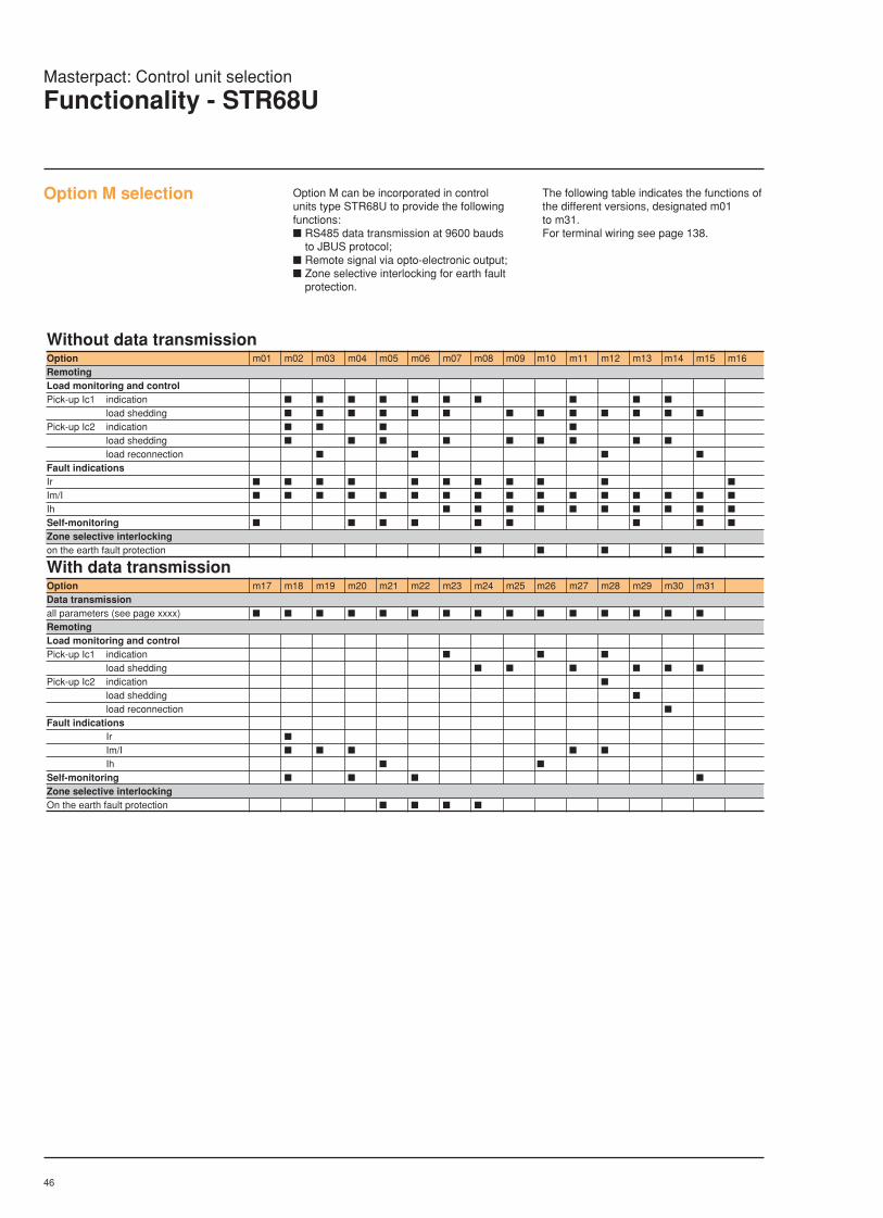
Option M selection Option M can be incorporated in controlunits type STR68U to provide the followingfunctions: RS485 data transmission at 9600 bauds
to JBUS protocol; Remote signal via opto-electronic output; Zone selective interlocking for earth fault
protection.
The following table indicates the functions ofthe different versions, designated m01to m31.For terminal wiring see page 138.
Without data transmissionOption m01 m02 m03 m04 m05 m06 m07 m08 m09 m10 m11 m12 m13 m14 m15 m16RemotingLoad monitoring and controlPick-up Ic1 indication
load shedding
Pick-up Ic2 indication
load shedding
load reconnection
Fault indicationsIr
Im/I
Ih
Self-monitoring
Zone selective interlockingon the earth fault protection
With data transmissionOption m17 m18 m19 m20 m21 m22 m23 m24 m25 m26 m27 m28 m29 m30 m31Data transmissionall parameters (see page xxxx)
RemotingLoad monitoring and controlPick-up Ic1 indication
load shedding
Pick-up Ic2 indication
load shedding
load reconnection
Fault indicationsIr
Im/I
Ih
Self-monitoring
Zone selective interlockingOn the earth fault protection
Masterpact: Control unit selection
Functionality - STR68U

47
Factory adjustmentsThe STR68U control unit is factory adjustedas follows:
LT setting Ir Intime delay tr 480 s
ST pick-up Im 4 Intime delay tm 0,2 s
INST pick-up I maxiT earth fault pick-up Ih 0,2 In
time delay th 0,1 sload monitor Ic1 In
Ic2 In
Earth fault protection (option T)
Operating zonesBasic functions: long time LT,short time ST, instantaneous INST
2
5
Ir Im
3
I I
t
0
1
4
I2t ON
I2t OFF
I
t
0
T1
T2
I2t ON
I2t OFF
overcurrent settings1 : LT setting Ir (long time)2 : LT time delay tr (long time)3 : ST pick-up Im ( short time)4 : ST time delay tm ( short time)5 : INST pick-up I (instantaneous)
earth fault protection settingsT1 : earth fault pick-up IhT2 : earth fault time delay th
load monitoring and control(option M)Operation with 2 load limit pick-ups
I
t
0
Ic1Ic2
I
t
0
Ic1Ic2
load monitoring and control settingsIc1 pick-up (load limit)Ic2 pick-up (load limit)
load monitoring and control settingsIc1 pick-up (load limit)Ic2 pick-up (load reconnection)
Operation with 1 load limit and 1 loadreconnection pick-up
Masterpact: Control unit selection
Functionality - STR68U
I2t ON
I2t OFF
I2t ON
I2t OFF

48
I
t
0
1
Im
Selection table
Im adjustable M10-20-40DC M60-80DC(accuracy ± 20 %)1.5 to 3 kA
3 to 6 kA
6 to 12 kA
10 to 20 kA
9 to 18 kA
12 to 24 kA
20 to 40 kA
IM 3 kA
reset
dina
IM 1,5 kA
D.E.F
1
Masterpact: Control unit selection
General characteristics and functionsDINA for DC applications
Trip-unit selectionThe DINA trip unit is an adjustable,instantaneous magnetic trip unit thatprovides protection against short circuits (1).There are seven versions of the DINA tripunit offering different magnetic settingthresholds (see the selection table below).Overload protection must be provided by anexternal relay (not supplied).Similar to the AC version, this trip unit isequipped as standard with four auxiliaryswitches (2 O + 2 F) and a fault-tripindication switch (SDE).

49
Battery module (PIL)Complementary to the F option for STR 38and STR 58 trip units. Enables recall of thelast fault trip indication, without the need foran external power source.
Interface module ET44Compulsory with the data transmissionoption on the STR 68 trip unit, the ET44interface module allows: Setting of the transmission speed; Circuit breaker address selection
Remote operation of the circuit breaker viaconnection to building managementSCADA systems
Power supply: 24 V DC with galvanicisolation, or AD type power module.
relay module (MR6)For relaying of information from outputs ofmodules m01 to m32 of control unit STR 68via output changeover contacts
10 A/220 V AC or 3 A/24 V DC.
Power supply module (AD) is required.
Power supply module (AD)These modules can be used to powercontrol unit complementary functions whichcannot be self-powered by the built-incurrent transformers: STR 38 and STR 58: fault type indication
(F); STR 58: segregated alarm switch (V); STR 58: communication option (COM); STR 28, STR 38, STR 58: ammeter (I) for
load less than 20% of In.
STR 68: indication and saving ofmeasurements, alarms, maintenanceindicator…;
MR6 module.These modules protect the trip unit fromtransient overvoltages due to galvanicisolation.Available voltages: AC 50/60 Hz: 110 V, 220 V or 380 V
(–20 %; +15 %) (consumption 10 VA); DC : 24/30 V, 48/60 V, 125 V (±20 %)
(consumption 10 W).
Battery module (BAT)Providing a complement to the AD module,the battery module provides backup powerfor display indications and maintenanceindicator data in the event of a power failure.Float connected between the power supplyand the control unit, it ensures a backuptime of approximately:
12 h with STR 38 and STR 58 controlunits;
1.5 h with STR 68 control unit.
Installation: on vertical plate or symmetricalrail. (ambient temperature from: 0 °C to+50 °C).
Mini test kit (BU)This self-contained portable unit is used: For control unit STR 68, to power, check
and carry out adjustments and tests onthe breaker/control unit assembly;
For other control units, to check controlunit operation and breaker tripping.
Power supply: five 9 V alkaline batteries (notsupplied).This test kit is common to the Masterpact,Compact NS, C, CM ranges.
Portable test kit for STR 18to STR 58The calibration test kit is used to check theoperation of the trip unit by measuring theactual trip time:
Long-time protection;
Short-time protection;
Instantaneous protection;
Earth-fault protection;
Power supply: 110, 220 V AC 50/60 Hz.
This test kit is common to the Masterpact,Compact NS, C, CM ranges.
Masterpact: Control unit selection
Accessories
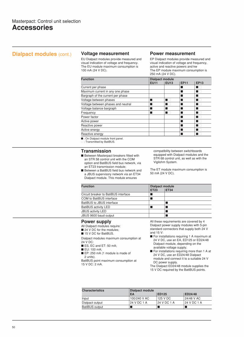
50
Voltage measurementEU Dialpact modules provide measured andvisual indication of voltage and frequency.The EU module maximum consumption is100 mA (24 V DC).
Power measurementEP Dialpact modules provide measured andvisual indication of voltage and frequency,active and reactive powers and kwThe EP module maximum consumption is250 mA (24 V DC).
Dialpact modules (cont.)
Function Dialpact moduleEU11 EU13 EP11 EP13
Current per phase
Maximum current in any one phase
Bargraph of the current per phase
Voltage between phases
Voltage between phases and neutral
Voltage balance bargraph
Frequency
Power factor
Active power
Reactive power
Active energy
Reactive energy
: On Dialpact module front panel. : Transmitted by BatiBUS.
Transmission Between Masterpact breakers fitted with
an STR 58 control unit with the COMoption and BatiBUS field bus network, viaan ET23 transmission module;
Between a BatiBUS field bus network anda JBUS supervisory network via an ET34Dialpact module. This module ensures
Function Dialpact moduleET23 ET34
Circuit breaker to BatiBUS interface
COM to BatiBUS interface
BatiBUS to JBUS interface
BatiBUS activity LED
JBUS activity LED
JBUS 9600 baud output
compatibility between switchboardsequipped with Dialpact modules and theSTR 68 control unit, as well as with theVigilohm System.
The ET module maximum consumption is50 mA (24 V DC).
Power supplyAll Dialpact modules require: 24 V DC for the modules; 15 V DC for BatiBUS.
Dialpact modules maximum consumption at24 V DC: ES, EC and ET: 50 mA; EU: 100 mA; EP: 250 mA (1 module is made of
2 units).BatiBUS point maximum consumption at15 V DC: 2 mA.
All these requirements are covered by 4Dialpact power supply modules with 5-pinstandard connectors that supply both 24 Vand 15 V: For installations requiring 1 A maximum at
24 V DC, use an EA, ED125 or ED24/48Dialpact module, depending on theavailable voltage supply;
For installations requiring more than 1 A at24 V DC, use an ED24/48 Dialpactmodule and connect it to a suitable 24 VDC power supply.
The Dialpact ED24/48 module supplies the15 V DC required by the BatiBUS points.
Characteristics Dialpact moduleEA ED125 ED24/48
Input 100/240 V AC 125 V DC 24/48 V ACDialpact output 24 V DC 1 A 24 V DC 1 A 24 V DC 1 ABatiBUS output
Masterpact: Control unit selection
Accessories

51
The protection functions and most of theoptions available for the STR control unitsare self-powered. An auxiliary power supplyis nevertheless required for certain uses.
Self-powered Auxiliary power supplyDirect AD + BAT Terminals Batteryconnection modules
STR 28 / 58Protection : LT, ST, INST YesOption I if I ≥ 20% In Yes
if I < 20% In No No (1) Yes (2) F1/F2 NoOption F No No (1) Yes F1/F2 YesOption FV No No (1) Yes F1/F2 NoOption ALR YesOption R YesOption T/W if Ih ≥ 0.2 x In Yes
if Ih < 0.2 x In No No (1) Yes F1/F2 No
STR 68Protection : LT, ST, INST, T, W Yes
Other functions : see next page
(1) Not recommended: possible with a 24 V DC source, class 2, 1 Watt, ripple factor < 1%.(2) Display will in this case be "". Auxiliary supply allows recall of max values.
Masterpact: Control unit selection
Auxiliary power supplies
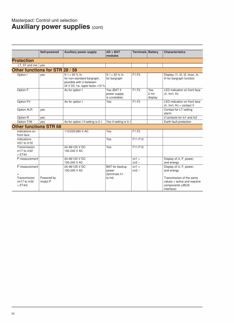
52
Self-powered Auxiliary power supply AD + BAT Terminals Battery Characteristicsmodules
Protection LT, ST and inst. yes
Other functions for STR 28 / 58Option I yes If: I < 20 % In If: i < 20 % In F1.F2 Display: I1, I2, I3, Imax, In,
for non-standard bargraph, for bargraph Ih for bargraph functionpossible with U between24 V DC 1w, ripple factor <10 %
Option F As for option I Yes (BAT if F1.F2 Yes LED indication on front facepower supply 2 mn (Ir, Im/I, Ih)is unreliable) display
Option FV As for option I Yes F1.F2 LED indication on front face(Ir, Im/I, Ih) + contact V
Option ALR yes Contact for LT settingalarm
Option R yes 2 contacts for Ic1 and Ic2Option T/W yes As for option I if setting is 0.1 Yes if setting is 0.1 Earth fault protection
Other functions STR 68Indications on 110/220/380 V AC Yes F1.F2front faceIndications Yes F11.F12m01 to m16Transmission 24-48/125 V DC Yes F11.F12m17 to m32 100-240 V AC+ ET44P measurement 24-48/125 V DC cn1 + Display of U, F, power,
100-240 V AC cn2 – and energyP measurement 24-48/125 V DC BAT for backup cn1 + Display of U, F, power,
100-240 V AC power cn2 – and energy+ (terminals h1Transmission Powered by to h4) Transmission of the same(m17 to m32 modul P values + active and reactive+ ET44) components (JBUS
interface)
Masterpact: Control unit selection
Auxiliary power supplies (cont)

53

54

55
LV air circuit breakersand switch-disconnectors
Masterpact800 to 6300 Amp
Accessories
page
Undervoltage, shunt,
closing releases 56
Auxiliary switches 57
Electrical operating mechanism 58
Operations counter 58
Safety shutters 59
Arc chute covers 59
Interphase barriers 59
Door gasket 60
Auxiliary wiring connection 60
Current rating interlock 60
Locking facilities 61
Section 4
4
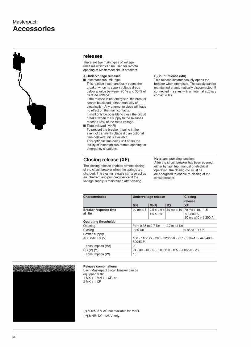
56
Masterpact:
Accessories
B)Shunt release (MX)This release instantaneously opens thebreaker when energised. The supply can bemaintained or automatically disconnected. Ifconnected in series with an internal auxiliarycontact (OF).
releasesThere are two main types of voltagereleases which can be used for remoteopening of Masterpact circuit breakers.
A)Undervoltage releases Instantaneous (MN)type
This release instantaneously opens thebreaker when its supply voltage dropsbelow a value between 70 % and 35 % ofits rated voltage.If the release is not energised, the breakercannot be closed (either manually ofelectrically). Any attempt to close will haveno effect on the main contacts.It shall only be possible to close the circuitbreaker when the supply to the releasesreaches 85% of the rated voltage.
Time delayed (MNR)To prevent the breaker tripping in theevent of transient voltage dip an optionaltime delayed unit is available.This optional time delay unit offers thefacility of instantanious remote opening foremergency situations.
Closing release (XF)The closing release enables remote closingof the circuit breaker when the springs arecharged. The closing release can also act asan inherrent anti-pumping device, if thevoltage supply is maintained after closing.
Note: anti-pumping function:After the circuit breaker has been opened,either by fault trip, manual or electricaloperation, the closing coil must bede-energised to enable re-closing of thecircuit breaker.
Characteristics Undervoltage release Closing release
MN MNR MX XFBreaker response time 90 ms ± 5 0.5 s-0.9 s 50 ms ± 10 70 ms + 10, – 15at Un 1.5 s-3 s i 3 200 A
80 ms ±10 > 3 200 AOperating thresholdsOpening from 0.35 to 0.7 Un 0.7 to 1.1 UnClosing 0.85 Un 0.85 to 1.1 UnPower supplyAC 50/60 Hz (V) 100 - 110/127 - 200 - 220/250 - 277 - 380/415 - 440/480 -
500/525(*)
consumption (VA) 20DC (V) (**) 24 - 30 - 48 - 60 - 100/110 - 125 - 200/220 - 250 consumption (W) 15
(*) 500/525 V AC not available for MNR.
(**) MNR: DC, 125 V only.
Release combinationsEach Masterpact circuit breaker can beequipped with:1 MX + 1 MN + 1 XF, or2 MX + 1 XF

57
Changeover switches to indicate "connected"position "CE"
Double break changeover switches "OF"
Auxiliary switchesIn addition to the main contact positionindication, 3 auxiliary switch blocks areavailable to indicate breaker open or closed. Standard: 4 contacts (O) (2 normally
open 2 normally closed); Optional: 4 directly-operated double
break changeover switches (OF) whichoperate only when the minimum isolatingdistance between the main contacts isreached;
Optional: 24 additional changeoverswitches (OFSUP block). Thesemicroswitches can be parallel connectedin pairs to increase the rated current andbreaking capacity (for drawout versiononly).
"Ready to close" contact(PF)Optional:This contact simultaneously indicates thefollowing: Breaker is open; Stored-energy mechanism is charged; Mechanism is correctly reset; Breaker opening pushbutton is not locked; No opening order is present.
This contact can be series connected to theclosing release (XF) to disable the anti-pumping function.
Connected/disconnectedposition carriage switchesIn addition to the front mounted "connected/test/disconnected" position indicator, twosets of optional carriage switches areavailable for the fixed chassis of drawouttype circuit breakers. A block of 4 changeover switches to
indicate "connected" position (CE); A block of 2 changeover switches to
indicate "disconnected" position (CD).The disconnected position is indicatedonly when the minimum isolating distancebetween the main and auxiliary circuitshas been achieved.
By series connection of these contactsadditional test indication can be achieved. 1 changeover switch to indicate "test"
position (CT).
"Spring charged"contact (CH)In addition to the local mechanical indicatorand the "ready to close" contact, the gear-motor limit switch changeover contact canindicate that the operating mechanism isready (spring charged). This contact issupplied as standard with the gear motor.
Fault-trip indication (SDE)As standard and independent from thedifferentiated fault indications on the controlunit, any fault-trip is indicated by: 1 fault-trip indicator/reset button; 1 changeover contact (SDE).The reset button must always be pressedafter a fault-trip to enable breaker re-closing.Optional: automatic reset, allowing remotebreaker closing without local resetting.
Auxiliary contacts Type O OF OFSUP SDE PF CE CD CT CHquantity changeover 4 24 1 1 4 2 1 1
NO 2 NONC 2 NC
Current rating (A) 10 10 10 10 10 10 10 10 10breaking capacity 110 V 15AC 50/60 Hz (A rms.) 240 V 10 10 10 10 10 10 10 10 10pf ≥ 0.3 380 V 6 10 6 5 5 6 6 6 6
480 V 6 10 6 6 6 6 6600 V 3 6 3 3 3 3 3
DC (A) 48 V 3 5 3 3 3 3 3 3 3L/R
Additional changeover switches ("OFSUP" block)
Masterpact:
Accessories
Contact characteristics

58
Masterpact:
Auxiliaries
Electrical chargingmechanismIs an optional extra to the standard manualcharging mechanism. The motor chargesand automatically recharges the stored-energy spring upon breaker closing whichenables fast O.C.O. cycle withoutre-charging.The manual mechanism remains availablefor emergency charging.
The electrical operating mechanism forremote operation should include: Gear motor(MCH); Closing release (XF); Shunt release (MX) or an undervoltage
release (MN) for opening; "Springs charged" limit switch changeover
contact (CH).The addition of the electrical operatingmechanism does not alter the overall circuitbreaker dimensions.
Characteristics Geared motor MCHPower supply 50/60 Hz (V) 100/127 - 200/240 - 250/277 - 380 - 415 - 440 - 480
consumption (VA) 180DC (V) 24/30 - 48/60 - 100/125 - 200/250 consumption (W) 180
Motor start-up surge 2 to 3 In for 0.1 sCharging time 3 to 4 s
Operation counter(CDM)Provided as an option to the electricaloperating mechanism. The operationalcounter provides numerical indication of thecircuit breaker open/close operating cycles.

59
a: Partitioning fixture (AC)b: Interphase barrier (EIP)
Fixed portion of drawout circuit breakers with arc chute andterminal shield
Fixed portion of drawout circuit breakers with safety shutters
Safety shutters (VO)Standard: mounted on the chassis of thedrawout version, the safety shuttersautomatically prevent access to the liveisolating contacts when the breaker is in thedisconnected or test position (degree ofprotection IP 20).
Masterpact:
Accessories
Terminal shield (CB)Standard: attached to the fixed portion ofdrawout circuit breakers, this cover preventsaccess to the electrical auxiliary connectionterminals.
Arc chute cover (CC)Standard: attached to the fixed portion ofdrawout circuit breakers, this covereliminates the requirement for a safetyclearance above the breaker (this option isnot compatible with versions fitted withfront (top) connection).
Interphase barrier(EIP)Optional: attached to the fixed portion ofdrawout circuit breakers, insulated partitionsfor vertical installation between busbarconnection pads to: Reinforce insulation at connection points in
instalations having sheathed or insulatedbusbars
Prevent arc propagation to the breaker inthe event of a line side fault on the mainbusbars.
partitioning fixture (AC)Optional: attached to the fixed portion ofdrawout breakers (except when equippedwith front connections), this fixture providesIP30 partitioning between the breakercompartment (accessible from the front) andthe busbar connections (located in the rear).It simplifies partition cut-outs.Example of partition cut-out forMasterpact M08 to M32.
Shutter lock (VVC)Optional: mounted on the chassis of thedrawout version, a removable and lockableslide (padlocks not supplied) is used to: lock the shutters in the closed position;, hold the shutters in the open position.A support is provided at the back of theframe to hold the slide when not in use.
360
445 (3 pôles) et 560 (4 pôles)
60
plan de fixationchâssis
référence
445 (3 pole) and 560 (4 pole)
chassisfixing
datum
a b

60
Auxiliaries for drawout version
Auxiliaries for fixed version
Door escutcheon (CDP)Standard: fixed to the cublicle door, thisframe provides an equipment seal function(degree of protection IP 405).Suitable for fixed and drawout patterns.
Earth connection (standard)The earth connection terminal (drawoutpattern) is on the left hand side of thechassis. It is marked with the symbol t
Transparent cover (CCP)Optional: hinge-mounted and equipped withscrew type locking device, this cover isdesigned for use with the door escutcheon(CDP). It provides a degree of protection ofIP549.Suitable for fixed and drawout patterns.
Auxiliary connectionFixed versionConnection by one or two plugs,disconnectable and accessible from the front(screwless tunnel terminals for flex cable upto 2.5 mm2).
Drawout version Standard: connection to a terminal block
in the front of the fixed frame (screwlesstunnel terminals for flex cable up to2.5 mm2).The breaker auxiliary circuits areconnected by connection blocks thatoperate automatically to isolate theauxiliaries when the breaker is in"disconnected" position.On request, an additional 5-way terminalblock (BS) is available to provide fivecommon points.
"Connected/disconnect/test" positioncontactsInstalled on the fixed chassis, these contactsare directly connected by 6.35 mmconnectors.
Breaker rating/typeinterlockStandard: for drawout version only, thissystems allows only the correctly matchedbreakers (rating, type wiring, etc.) to beinserted in a given fixed frame.Two matching parts (1 for the fixed chassisand 1 for the moving portion) can be used tocreate 20 different user selectedcombinations.
Masterpact:
Accessories

61
"Disconnected","connected" and "test"position locking (1)
Located on the cassette and accessible withthe cubicle door locked, this system isavailable in two versions:c "Disconnected" position locking;v As standard by a padlocking device (1 to 3
padlocks not supplied),v Optional: by a locking device with 1 or 2
Profalux key locks;c "Disconnected", "connected" and "test"
position locking (optional);v By a padlocking device, with 1 to 3
padlocks not supplied (VEC),v By a locking device, with 1 or 2 Profalux
key locks (VSPEC),
Padlocks 1 keylock 2 keylocks"disconnected" standard"disconnected" "disconnected" standard optional"disconnected" "disconnected" "disconnected" standard optional optional"disconnected, connected"*"disconnected, "disconnected, connected"* connected"*"disconnected, "disconnected, "disconnected, connected"* connected" * connected"*
Pushbutton locking deviceOptional: this padlockable device (padlocksnot supplied) prevents direct operation of thecircuit breaker by preventing operation of the"on" and "off" pushbuttons. This lockingdevice is provided with sealing facility asstandard.
(1) Keylock typesProfalux B24 D4ZRonis 1351 BKirk CN22-12Castell SK7113/1Trayvou L1P1E
"Off" position lockingdeviceOptional: key lock for locking the breaker inthe "off" position by use of a Profalux,Castell or key lock.
Pushbutton locking deviceBy padlocks (not supplied) VBP
"Off " position locking device (1)
1 Profalux key lock VSPA12 Profalux key locks, identical profiles VSPA2adaptation fixture for 1 Profalux key lock, lock not supplied VSPRACOn request1 Ronis key lock VSRA12 Ronis key locks, identical profiles VSRA2Adaptation for 1 Castell key lock, lock not supplied VSCAAdaptation for 1 Kirk key lock, lock not supplied VSKA
Remarksc The keylocks are of the captive key type,
i.e. key free when locked;c Profalux and Ronis keylocks can be used
together;c A second Profalux or Ronis lock, identical
to the one mounted on the chassis, canbe supplied separately.
Masterpact:
Accessories
* Optional
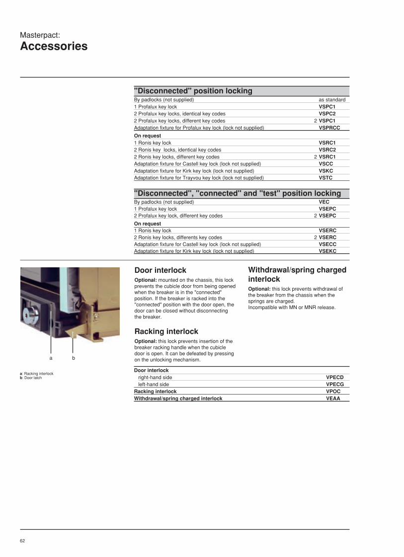
62
"Disconnected" position lockingBy padlocks (not supplied) as standard1 Profalux key lock VSPC12 Profalux key locks, identical key codes VSPC22 Profalux key locks, different key codes 2 VSPC1Adaptation fixture for Profalux key lock (lock not supplied) VSPRCC
On request1 Ronis key lock VSRC12 Ronis key locks, identical key codes VSRC22 Ronis key locks, different key codes 2 VSRC1Adaptation fixture for Castell key lock (lock not supplied) VSCCAdaptation fixture for Kirk key lock (lock not supplied) VSKCAdaptation fixture for Trayvou key lock (lock not supplied) VSTC
"Disconnected", "connected" and "test" position lockingBy padlocks (not supplied) VEC1 Profalux key lock VSEPC2 Profalux key lock, different key codes 2 VSEPC
On request1 Ronis key lock VSERC2 Ronis key locks, differents key codes 2 VSERCAdaptation fixture for Castell key lock (lock not supplied) VSECCAdaptation fixture for Kirk key lock (lock not supplied) VSEKC
Door interlockOptional: mounted on the chassis, this lockprevents the cubicle door from being openedwhen the breaker is in the "connected"position. If the breaker is racked into the"connected" position with the door open, thedoor can be closed without disconnectingthe breaker.
Racking interlockOptional: this lock prevents insertion of thebreaker racking handle when the cubicledoor is open. It can be defeated by pressingon the unlocking mechanism.
Withdrawal/spring chargedinterlockOptional: this lock prevents withdrawal ofthe breaker from the chassis when thesprings are charged.Incompatible with MN or MNR release.
a: Racking interlockb: Door latch
Door interlock right-hand side VPECD left-hand side VPECGRacking interlock VPOCWithdrawal/spring charged interlock VEAA
a b
Masterpact:
Accessories

63
LV air circuit breakersand switch-disconnectors
Masterpact800 to 6300 Amp
Source changeover systems
page
Manual Source changeover 64
Remote Source changeover 65
Automatic changeover with
2 devices 66
Automatic changeover with
3 devices 67
Controller option selection 68
Auto source changeovercontrollers
Controller type BA
(standard changeover) 69
Controller type UA
(advanced changeover) 71
Section 5
5

64
Masterpact:
Manual source changeover systems
All combinations are possible: fixed anddrawout versions, three pole and four pole,different current ratings, circuit breakers orswitch disconnectors.All control units can be used on the circuitbreakers.
Mechanical interlocking byconnecting rods for 2 or 3vertically-mounted breakersThis comprises:
c 2 or 3 Masterpact circuit breakers orswitch-disconnectors;
c An adaptation fixture on the right side ofeach breaker;
c 1 or 2 sets of connecting rods with no-slipadjustments;
The complete interlock kit is supplied forassembly by the customer.The changeover system with interlocking byconnecting rods is also available in a versionwhich is factory mounted on a steel frame.
Maximum distance between fixingplanes: 900 mm.
Mechanical interlocking bycables for 2 side-by-sidebreakersThis comprises:
c 2 Masterpact circuit breakers or switch-disconnectors;
c An adaptation fixture on the right side ofeach breaker;
c A set of cables with no-slip adjustments;The complete kit is supplied for assemblyby the customer.
Distance between fixing planes:c Maximum: 2 000 mm;c Minimum: breaker height with arc chute
cover (see pages 130).
Device combinations Assembly and installationThe various parts of the Masterpactautomatic source-changeover system aremounted and connected by the user. Nocircuit breaker modifications are required.The wiring diagrams are shown on pagesXX.The Masterpact automatic source-changeover system may also be suppliedfactory-wired and mounted on a metalframe.

65
Power circuit Possible combinations Configuration type wiring dia.
Interlocking with 3 breakers3 sources, only one breaker closed
Interlocking with 3 breakers2 sources + 1 coupling
Electrical interlocking 685363Automatic controlWith generator set 688784With permanent "alternative" 688942source
Interlocking with 2 breakers Q1 Q20 00 11 0
Q1 Q2
Q1 Q2 Q3
Q1 Q2 Q3
Masterpact:
Automatic source-changeover systemsAutomatic control: by customer
The electrical interlocking system andautomatic control system for multiplesources must be wired by the user andused in conjunction with the mechanicalinterlocking system.Typical wiring configurations are availableon request. See examples below.
Necessary auxiliaries and accessoriesTo implement the configurations detailedbelow, each Masterpact circuit breaker mustbe equipped with:
c A motor mechanism (MCH);
c A shunt release (MX);
c A "ready to close" contact (PF);
c A block of 4 changeover switches (OF);
c An additional terminal block (BS) and ablock of 4 "connected" position switches(CE) for changeover systemsincorporating drawout breakers.
Option with "lockout after fault"With this option, the circuit breaker must bereset manually after a fault trip.
Interlocking with 3 breakers2 "mains" sources + 1 "alternative"source
Q1 Q2 Q3
Q1 Q2 Q30 0 01 0 00 0 11 1 00 1 0
Automatic control with permanent"alternative" sourceWith lockout after fault 685366Without lockout after fault 688183Automatic control with generator setWith lockout after fault 689642Without lockout after fault 689644
Electrical interlockingWith lockout after fault 688188Without lockout after fault 688187
Q1 Q2 Q30 0 01 0 00 1 00 0 1
Q1 Q2 Q30 0 01 0 00 1 00 0 11 1 00 1 11 0 1
Electrical interlockingWith lockout after fault 688189Without lockout after fault 688190Automatic control 689651

66
Masterpact:
Automatic source-changeover systemsAutomatic control: by Merlin Gerin controller
Masterpact source-changeover systems canbe used to implement various configurationsinvolving a number of incoming feeders.The two or three Masterpact circuit breakersor switch-disconnectors used aremechanically interlocked to prevent certaincombinations of operations.
All types of Masterpact devices may be fittedin combination with each other (fixed anddrawout versions, three-pole and four-pole,with different ratings).
The devices may be arranged:
Vertically, i.e. stack-mounted andinterconnected by a set of solid interlockrods.
Horizontally (two only), i.e. side-by-sideand interconnected by a set of Bowdentype cables. An electrical interlock mustbe used when the source changeover ispart of an automatic system.
R
N
N
R
auto
stop
manu
UN
ON / I
OFF / O
fault
UR
ON / I
OFF / O
fault
UN = O
UN = 1
MERLIN GERIN
STOP generator
N
R
test
BU
S
Test
MERLIN GERIN
multi 9
P25M
660V
AC3-IEC292-1
0 . OFF
Test
MERLIN GERIN
multi 9
P25M
660V
AC3-IEC292-1
0 . OFF
4
5
6
R
N
N
0,5s
R
0,5s
UN
ON / I
OFF / O
fault
UR
ON / I
OFF / O
fault
UN = O
UN = 1
MERLIN GERIN
stop
manu
N
test
R
Automatic source-changeover system with 2 devices
1
2
3
3
1 2
3
With controller In this case, conditional changeoversbetween the "Mains" and "Standby" sourcesare initiated by a Merlin Gerin controller.
A Masterpact automatic source-changeover system with 2 devicescomprises:1 - Circuit breaker QN connected to the
"Mains" source;
2 - Circuit breaker QR connected to the"Standby" source;
3 - Mechanical interlocking system by rodsor cables;
Automatic control of the system can beprovided by adding:4 - Electrical interlocking unit IVE;
5 - Auxiliaries control plate ACP;
6 - Controller BA or UA.
Each Masterpact circuit breaker isequipped with: A motor mechanism;
A shunt release (MX);
A "ready to close" contact (PF);
A block of 4 changeover switches (OF);
An additional terminal block (BS) and ablock of 4 "connected" position switches(CE) for source-changeover systemsmade up of drawout breakers.
Without controller In this case, the automatic control system toinitiate changeovers between the "Mains"and "Standby" sources under predefinedconditions must be provided by thecustomer.
Masterpact automatic source-changeover system
Controller
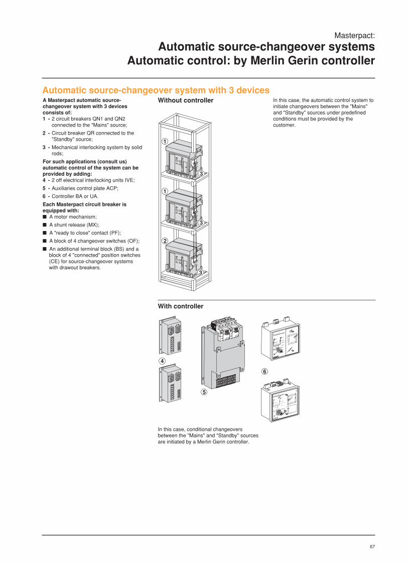
67
1
1
2
3
3
3
Automatic source-changeover system with 3 devicesA Masterpact automatic source-changeover system with 3 devicesconsists of:1 - 2 circuit breakers QN1 and QN2
connected to the "Mains" source;
2 - Circuit breaker QR connected to the"Standby" source;
3 - Mechanical interlocking system by solidrods;
For such applications (consult us)automatic control of the system can beprovided by adding:4 - 2 off electrical interlocking units IVE;
5 - Auxiliaries control plate ACP;
6 - Controller BA or UA.
Each Masterpact circuit breaker isequipped with: A motor mechanism;
A shunt release (MX);
A "ready to close" contact (PF);
A block of 4 changeover switches (OF);
An additional terminal block (BS) and ablock of 4 "connected" position switches(CE) for source-changeover systemswith drawout breakers.
Without controller In this case, the automatic control system toinitiate changeovers between the "Mains"and "Standby" sources under predefinedconditions must be provided by thecustomer.
With controller
R
N
N
R
auto
stop
manu
UN
ON / I
OFF / O
fault
UR
ON / I
OFF / O
fault
UN = O
UN = 1
MERLIN GERIN
STOP generator
N
R
test
BU
S
Test
MERLIN GERIN
multi 9
P25M
660V
AC3-IEC292-1
0 . OFF
Test
MERLIN GERIN
multi 9
P25M
660V
AC3-IEC292-1
0 . OFF
4
5
6
R
N
N
0,5s
R
0,5s
UN
ON / I
OFF / O
fault
UR
ON / I
OFF / O
fault
UN = O
UN = 1
MERLIN GERIN
stop
manu
N
test
R
In this case, conditional changeoversbetween the "Mains" and "Standby" sourcesare initiated by a Merlin Gerin controller.
Masterpact:
Automatic source-changeover systemsAutomatic control: by Merlin Gerin controller
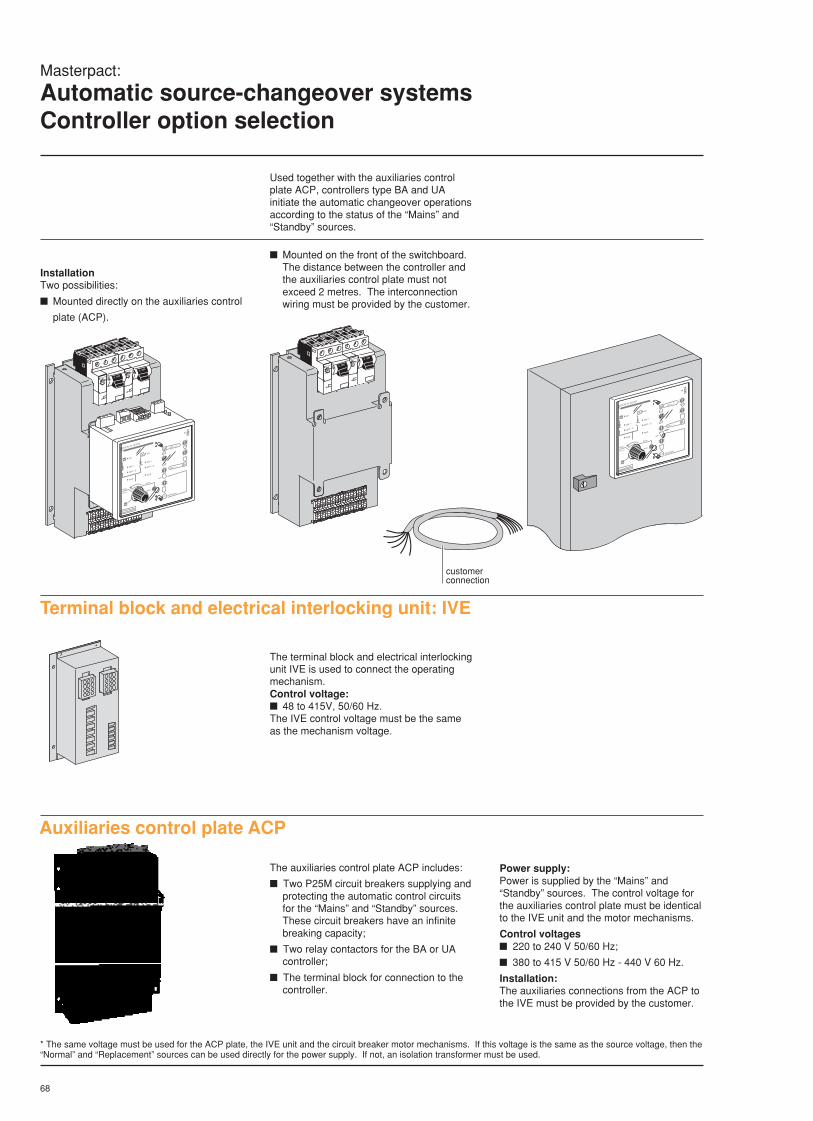
68
Masterpact:
Automatic source-changeover systemsController option selection
Used together with the auxiliaries controlplate ACP, controllers type BA and UAinitiate the automatic changeover operationsaccording to the status of the “Mains” and“Standby” sources.
Auxiliaries control plate ACP
The auxiliaries control plate ACP includes:
Two P25M circuit breakers supplying andprotecting the automatic control circuitsfor the “Mains” and “Standby” sources.These circuit breakers have an infinitebreaking capacity;
Two relay contactors for the BA or UAcontroller;
The terminal block for connection to thecontroller.
Power supply:Power is supplied by the “Mains” and“Standby” sources. The control voltage forthe auxiliaries control plate must be identicalto the IVE unit and the motor mechanisms.
Control voltages 220 to 240 V 50/60 Hz;
380 to 415 V 50/60 Hz - 440 V 60 Hz.
Installation:The auxiliaries connections from the ACP tothe IVE must be provided by the customer.
InstallationTwo possibilities:
Mounted directly on the auxiliaries control
plate (ACP).
Test
MERLIN GERIN
multi 9
P25M
660V
AC3-IEC292-1
0 . OFF
Test
MERLIN GERIN
multi 9
P25M
660V
AC3-IEC292-1
0 . OFF
R
N
N
R
auto
stop
manu
UN
ON / I
OFF / O
fault
UR
ON / I
OFF / O
fault
UN = O
UN = 1
MERLIN GERIN
STOP generator
N
R
test
BU
S
Mounted on the front of the switchboard.The distance between the controller andthe auxiliaries control plate must notexceed 2 metres. The interconnectionwiring must be provided by the customer.
R
N
N
R
auto
stop
manu
UN
ON / I
OFF / O
fault
UR
ON / I
OFF / O
fault
UN = O
UN = 1
MERLIN GERIN
STOP generator
N
R
test
BU
S
Test
MERLIN GERIN
multi 9
P25M
660V
AC3-IEC292-1
0 . OFF
Test
MERLIN GERIN
multi 9
P25M
660V
AC3-IEC292-1
0 . OFF
customerconnection
Terminal block and electrical interlocking unit: IVE
The terminal block and electrical interlockingunit IVE is used to connect the operatingmechanism.Control voltage: 48 to 415V, 50/60 Hz.The IVE control voltage must be the sameas the mechanism voltage.
* The same voltage must be used for the ACP plate, the IVE unit and the circuit breaker motor mechanisms. If this voltage is the same as the source voltage, then the“Normal” and “Replacement” sources can be used directly for the power supply. If not, an isolation transformer must be used.
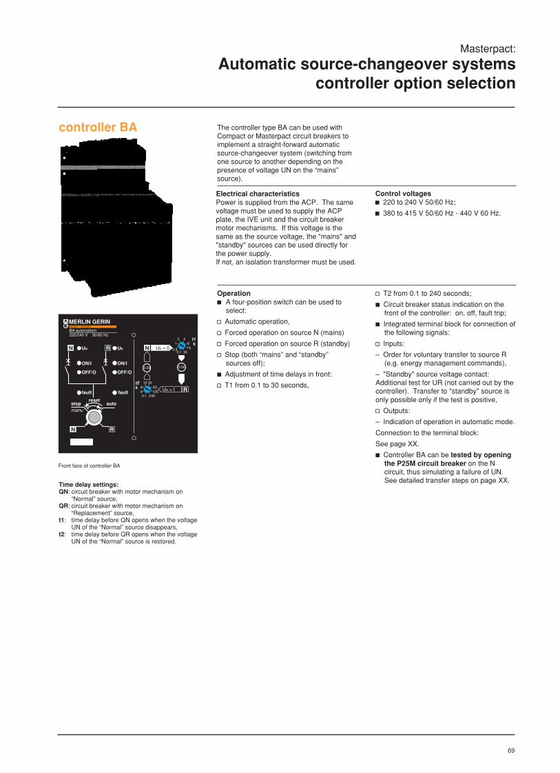
69
Front face of controller BA
Masterpact:
Automatic source-changeover systemscontroller option selection
Time delay settings:QN: circuit breaker with motor mechanism on
“Normal” source,QR: circuit breaker with motor mechanism on
“Replacement” source,t1: time delay before QN opens when the voltage
UN of the “Normal” source disappears,t2: time delay before QR opens when the voltage
UN of the “Normal” source is restored.
controller BA
MERLIN GERINBA automatism220/240 V 50/60 Hz
N R
fault fault
UN UR
ON/I ON/I
OFF/O OFF/O
N
R
UN = 0
UN = I
4281
0.50.1
1530
3015608
40.1
120240
t1 s
t2s
compact / masterpact
0.5s 0.5s
N R
stopmanu
autoreset
The controller type BA can be used withCompact or Masterpact circuit breakers toimplement a straight-forward automaticsource-changeover system (switching fromone source to another depending on thepresence of voltage UN on the “mains”source).
Control voltagesc 220 to 240 V 50/60 Hz;
c 380 to 415 V 50/60 Hz - 440 V 60 Hz.
Electrical characteristicsPower is supplied from the ACP. The samevoltage must be used to supply the ACPplate, the IVE unit and the circuit breakermotor mechanisms. If this voltage is thesame as the source voltage, the "mains" and"standby" sources can be used directly forthe power supply.If not, an isolation transformer must be used.
Operationc A four-position switch can be used to
select:
v Automatic operation,
v Forced operation on source N (mains)
v Forced operation on source R (standby)
v Stop (both “mains” and “standby”sources off);
c Adjustment of time delays in front:
v T1 from 0.1 to 30 seconds,
v T2 from 0.1 to 240 seconds;
c Circuit breaker status indication on thefront of the controller: on, off, fault trip;
c Integrated terminal block for connection ofthe following signals:
v Inputs:
– Order for voluntary transfer to source R(e.g. energy management commands),
– "Standby" source voltage contact:Additional test for UR (not carried out by thecontroller). Transfer to "standby" source isonly possible only if the test is positive,
v Outputs:
– Indication of operation in automatic mode.
Connection to the terminal block:
See page XX.
c Controller BA can be tested by openingthe P25M circuit breaker on the Ncircuit, thus simulating a failure of UN.See detailed transfer steps on page XX.

70
RN
OI
RN
IO
RN
OI
RN
IO
"auto"
operat. onsource N
UN fail (duration > t1) or voluntaryswitching order received
t > 0,5 s
QR closed
t > 0,5 s
QN closed
QN opens
QR closes
QR opens
QN closes
4-position switch N and UN present
QR opens
QN closes
operat. onsource N
QN closed
4-position switch in "R" position and"UR" present
QN opens
QR closes
QR closed
t > 0,5 s
operat. onsource R
end of reset
"stop"
off
It is not necessary to set controller BA to“stop” position before operating circuitbreakers QN or QR manually.
The circuit breakers will return to their initialstate when the controller is reset to “auto”.
note: source N = mains
source R = standby
QN and QR open
duration a 1 sreset
ccccc 4-position switch in "stop" position ccccc 4-position switch in "auto" position(automatic operation)
UN present for t > t2 or voluntaryswitching order stopped
ccccc 4-position switch in "N " position(forced operation on "mains" source)
action on 4-position switch
t > 0,5 s
action on 4-position switch
ccccc 4-position switch in "R" position(forced operation on "standby" source)
operat. onsource R
Masterpact:
Automatic source-changeover systemscontroller option selection
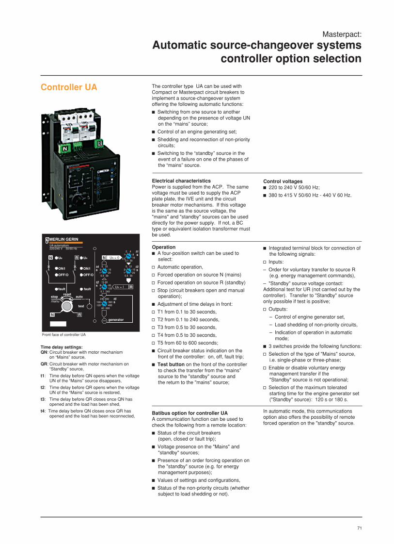
71
Masterpact:
Automatic source-changeover systemscontroller option selection
The controller type UA can be used withCompact or Masterpact circuit breakers toimplement a source-changeover systemoffering the following automatic functions:
c Switching from one source to anotherdepending on the presence of voltage UNon the “mains” source;
c Control of an engine generating set;
c Shedding and reconnection of non-prioritycircuits;
c Switching to the “standby” source in theevent of a failure on one of the phases ofthe “mains” source.
Electrical characteristicsPower is supplied from the ACP. The samevoltage must be used to supply the ACPplate plate, the IVE unit and the circuitbreaker motor mechanisms. If this voltageis the same as the source voltage, the"mains" and "standby" sources can be useddirectly for the power supply. If not, a BCtype or equivalent isolation transformer mustbe used.
Control voltagesc 220 to 240 V 50/60 Hz;
c 380 to 415 V 50/60 Hz - 440 V 60 Hz.
Operationc A four-position switch can be used to
select:
v Automatic operation,
v Forced operation on source N (mains)
v Forced operation on source R (standby)
v Stop (circuit breakers open and manualoperation);
c Adjustment of time delays in front:
v T1 from 0.1 to 30 seconds,
v T2 from 0.1 to 240 seconds,
v T3 from 0.5 to 30 seconds,
v T4 from 0.5 to 30 seconds,
v T5 from 60 to 600 seconds;
c Circuit breaker status indication on thefront of the controller: on, off, fault trip;
c Test button on the front of the controllerto check the transfer from the “mains”source to the "standby" source andthe return to the "mains" source;
c Integrated terminal block for connection ofthe following signals:
v Inputs:
– Order for voluntary transfer to source R(e.g. energy management commands),
– "Standby" source voltage contact:Additional test for UR (not carried out by thecontroller). Transfer to "Standby" sourceonly possible if test is positive;
v Outputs:
– Control of engine generator set,
– Load shedding of non-priority circuits,
– Indication of operation in automatic mode;
c 3 switches provide the following functions:
v Selection of the type of "Mains" source,i.e. single-phase or three-phase;
v Enable or disable voluntary energymanagement transfer if the"Standby" source is not operational;
v Selection of the maximum toleratedstarting time for the engine generator set("Standby" source): 120 s or 180 s.
Batibus option for controller UAA communication function can be used tocheck the following from a remote location:
c Status of the circuit breakers(open, closed or fault trip);
c Voltage presence on the "Mains" and"standby" sources;
c Presence of an order forcing operation onthe "standby" source (e.g. for energymanagement purposes);
c Values of settings and configurations,
c Status of the non-priority circuits (whethersubject to load shedding or not).
In automatic mode, this communicationsoption also offers the possibility of remoteforced operation on the "standby" source.
Controller UA
Front face of controller UA
Time delay settings:QN: Circuit breaker with motor mechanism
on “Mains” source,
QR: Circuit breaker with motor mechanism on“Standby” source,
t1: Time delay before QN opens when the voltageUN of the “Mains” source disappears,
t2: Time delay before QR opens when the voltageUN of the “Mains” source is restored,
t3: Time delay before QR closes once QN hasopened and the load has been shed,
t4: Time delay before QN closes once QR hasopened and the load has been reconnected,
MERLIN GERINUA automatism220/240 V 50/60 Hz
N R
N R
stopmanu
auto
test
reset
fault fault
UN UR
ON/I ON/I
OFF/O OFF/O
N
R
UN = 0
UN = I
STOP generator
4281
0.50.1
1530
105152
10.5
2030
105152
10.5
2030
3015608
40.1
120240
300240360160
12060
480600
t1 s
t3 s
t4s
t2s
t5s
compact / masterpact

72
RN
IO
RN
OI
RN
OI
RN
IO
operat. onsource N
genset off
genset startup
UN fails (duration > t1) or voluntaryswitching order received
UR present for t > 120 s or 180 s
t > t3
QR closes
QR closed
operat. onsource R genset on
t > t4
QN closes
QN closed
UN present for t > t5 and novoluntary switching order received
genset off
UR absent
4-position switch in "N" and UN
present
t > t4
QN closes
genset off
QN closed
4-position switch in "R" and UN
present
genset startup
UR present for t > 120 s ou 180 s
t > t3
QR closed
QR closes
genset on
"auto"
ccccc 4-position switch in "R" position(forced operation on "standby" source)
reset
end of reset
"stop"
stop
It is not necessary to set controller UA to“stop” position before operating circuitbreakers QN or QR manually.
The circuit breakers will return to their initialstate when the controller is reset to “auto”.
note: source N = mains
source R = standby
operat. onsource R
ccccc 4-position switch in "stop" position ccccc 4-position switch in "auto" position(automatic operation)
duration a 1 s
QN opens and loadshedding
UN present for t > t2 or voluntaryswitching order stopped
QR opens and loadreconnection
genset remains on
ccccc 4-position switch in "N" position(forced operation on "mains" source)
QR opens and loadshedding
operat. onsource N
action on 4-position switch
action on 4-position switch
QN opens and loadshedding
QN and QR open
Masterpact:
Automatic source-changeover systemscontroller option selection

73
LV air circuit breakersand switch-disconnectors
Masterpact80 to 6300 Amp
Complementary technicalinformation
page
Tripping curves (AC range) 74
Effect of ambient temperature (AC) 84
DC circuit brakers 85
Effect of ambient temperature (DC) 87
Section 6
6All Merlin Gerin tripping characteristics arealso available in our ‘protect’ softwarepackage.
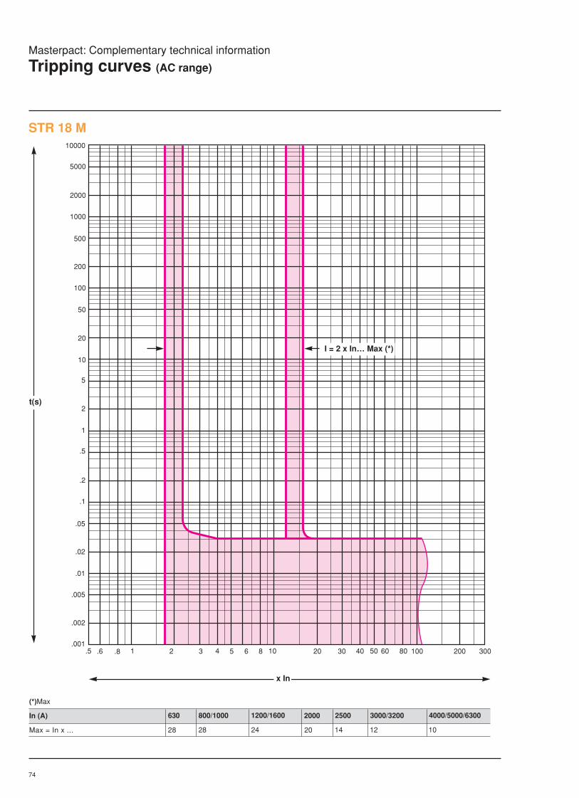
74
Masterpact: Complementary technical information
Tripping curves (AC range)
STR 18 M
.5 .6 .8 1 2 3 4 5 6 8 10 20 30 50 100 200 300.001
.002
.01
.02
.05
.1
.2
.5
1
2
5
10
20
.005
50
100
200
500
1000
2000
5000
10000
I = 2 x In… Max (*)
40 60 80
(*)Max
In (A)
Max = In x ...
1200/1600 2000 2500 3000/3200 4000/5000/6300800/1000
28 28 24 20 14 12 10
630
t(s)
x In
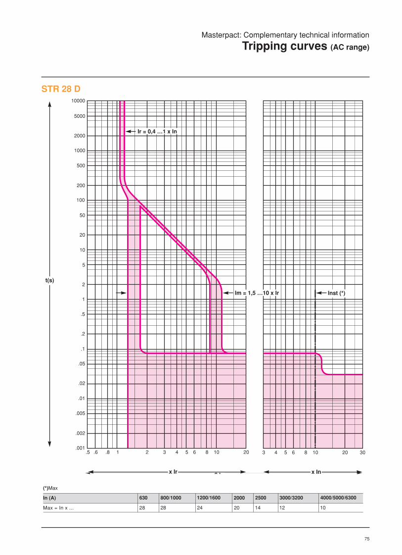
75
STR 28 D
.5 .6 .8 1 2 3 4 5 6 8 10 20 3 4 5 6 8 10 20 30.001
.002
.01
.02
.05
.1
.2
.5
1
2
5
10
20
50
100
200
500
1000
2000
5000
10000
.005
Ir = 0,4 …1 x In
Inst (*)
t(s)
x Ir x In
Im = 1,5 …10 x Ir
Masterpact: Complementary technical information
Tripping curves (AC range)
(*)Max
In (A)
Max = In x ...
1200/1600 2000 2500 3000/3200 4000/5000/6300800/1000
28 28 24 20 14 12 10
630
x I

76
Masterpact: Complementary technical information
Tripping curves (AC range) (cont.)
STR 38 S
.5 .6 .8 1 2 3 4 5 6 8 10 20 3 4 5 6 8 10 20 30.001
.002
.01
.02
.05
.1
.2
.5
1
2
5
10
20
50
100
200
500
1000
2000
5000
10000
.005
0,3
0,2
0,1 0,1
0
Ir = 0,4 …1 x In
I2t ON
I2t OFF
Inst (*)
0,3
0,4
0,2
(*)Inst
In (A)
I = In x ... (N-H)
1200/1600 2000 2500 3000/3200 4000/5000/6300
I = In x ... (L)
800/1000
28 12
-
630
t(s)
x Ir x Ir
Im = 1,5 …10 x Ir
14
28
10
24
8
20
6
14
6
10
-

77
STR 58 U
.5 .6 .8 1 2 3 4 5 6 8 10 20 3 4 5 6 8 10 20 30.001
.002
.01
.02
.05
.1
.2
.5
1
2
5
10
20
50
100
200
500
1000
2000
5000
10000
.005
0,3
0,2
0,1
0,3
0,2
0,1
Ir = 0,4 …1 x In
tr = 15…480s
I2t ON
I = 2 x In…Max (*)
I2t OFF
0,4
0
(*)Max
In (A)
Max = In x ... (N-H)
Max = In x ... (L)
t(s)
x Ir x In
Im = 1,5 …10 x Ir
1200/1600800/1000
28
630
14
28
10
24
8
2000 2500 3000/3200 4000/5000/6300
12
-
20
6
14
6
10
-
Masterpact: Complementary technical information
Tripping curves (AC range) (cont.)

78
Masterpact: Complementary technical information
Tripping curves (AC range) (cont.)
.05 .06 .08 .1 .2 .3 .4 .5 .6 .8 1 2 3 4 5 6 8 10 20 30.001
.002
.01
.02
.05
.1
.2
.5
1
2
5
10
20
.005
50
100
200
500
1000
2000
5000
10000
0,1
I2t ON
I2t OFF
Ih = 0,1…1 x InMax 1200A
0,2
0,30,4
t(s)
x In
In: CT ratingIh: earth fault protection pick-up (delay: th)
STR 38 S/STR 58 U: earth fault protection

79
.05 .06 .08 .1 .2 .3 .4 .5 .6 .8 1 2 3 4 5 6 8 10 20 30.001
.002
.01
.02
.05
.1
.2
.5
1
2
5
10
20
.005
50
100
200
500
1000
2000
5000
10000
tr1 = tr / 2
Ir = 0,4…1 x In
Ic1 = 0,8…1 x Ir
Ic2 = 0,5…1 x Ir
tr2 = tr / 4
t(s)
x In
Ir: LT protection current setting (delay: tr)Ic1: load-shedding pick-up 1 (delay: tr1)Ic2: load-shedding pick-up 2 (delay: tr2)
STR 38 S/STR 58 U: load monitoring
Masterpact: Complementary technical information
Tripping curves (AC range) (cont.)

80
Masterpact: Complementary technical information
Tripping curves (AC range) (cont.)
STR 68 U
.5 .6 .8 1 2 3 4 5 6 8 10 20 30 40 50 60 80 100 200 300.001
.002
.01
.02
.05
.1
.2
.5
.005
1
2
5
10
20
50
100
200
500
1000
2000
5000
10000
Ir = 0,4 …1 x In
tr = 15…480s
I2t ON
I2t OFF
INST (*)
0,4
0,3
0,2
0,1 0,1
0,2
0,3
0,4
t(s)
x In kA
Im = 0,4 …15 x In
(*)INST
In (A)
type H2: INST = 1.6 kA ... 50 kA
1000
type H1: INST =type L1: INST =
In or 1.6 kA ... 50 kA1.6 kA ... 11 kA
800 1250 1600 2000 2500 3200 4000 5000 6000
In ... 65 kA
In ... 15 kA
In ... 75 kA
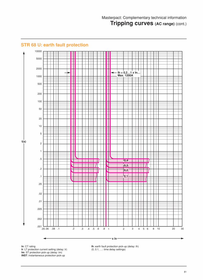
81
STR 68 U: earth fault protection
.05 .06 .08 .1 .2 .3 .4 .5 .6 .8 1 2 3 4 5 6 8 10 20 30.001
.002
.01
.02
.05
.1
.2
.5
1
2
5
10
20
.005
50
100
200
500
1000
2000
5000
10000
0,1
Ih = 0,2…1 x In…Max. 1200A
0,4
0,3
0,2
t(s)
x In
In: CT ratingIr: LT protection current setting (delay: tr)Im: ST protection pick-up (delay: tm) INST: instantaneous protection pick-up
Ih: earth fault protection pick-up (delay: th)(0, 0.1, …: time delay settings)
Masterpact: Complementary technical information
Tripping curves (AC range) (cont.)

82
Masterpact: Complementary technical information
Tripping curves (AC range) (cont.)
.05 .06 .08 .1 .2 .3 .4 .5 .6 .8 1 2 3 4 5 6 8 10 20 30.001
.002
.01
.02
.05
.1
.2
.5
1
2
5
10
20
.005
50
100
200
500
1000
2000
5000
10000
tr = 15…480s
Ir = 0,4…1 x In
Ic1 = 0,2…1 x In
Ic2 = 0,2…1 x In
tr1 = tr / 2
tr2 = tr / 4
t(s)
x In
Ic1: one load-shedding pick-up (delay: tr1)Ic2: another load-shedding pick-up (delay: tr2)
In: CT ratingIr: LT protection current setting (delay: tr)
STR 68 U: load monitoring with 2 load limits

83
STR 68: load monitoring with 1 load-shedding and 1 load-reconnection pick-up
.05.06 .08 .1 .2 .3 .4 .5 .6 .8 1 2 3 4 5 6 8 10 20 30.001
.002
.01
.02
.05
.1
.2
.5
1
2
5
10
20
.005
50
100
200
500
1000
2000
5000
10000
tr = 15…480s
Ir = 0,4…1 x In
Ic1 = 0,2…1 x In
Ic2 = 0,2…1 x In
tr1 = tr / 2
tr2 = 60s
t(s)
x In
Ic1: load-shedding pick-up (delay: tr1)Ic2: load-reconnection pick-up 2 (delay: tr2)
Masterpact: Complementary technical information
Tripping curves (AC range) (cont.)
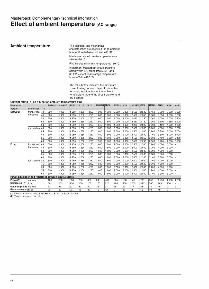
84
Masterpact: Complementary technical information
Effect of ambient temperature (AC range)
Ambient temperature The electrical and mechanicalcharacteristics are specified for an ambienttemperature between –5 and +60 °C.
Masterpact circuit breakers operate from–10 to +70 °C.
First closing minimum temperature: –30 °C.
In addition, Masterpact circuit breakerscomply with IEC standards 68.2.1 and68.2.2: exceptional storage temperaturefrom: –50 to +100 °C.
Current rating (A) as a function ambient temperature (°C)Masterpact M08N/H/L M10N/H/L M12N M12H M12L M16N/H M16L M20N/H M20L M25N/H M25L M32H M40H M50H M63HVersion connection T °CDrawout front or rear 40 800 1 000 1 250 1 250 1 250 1 600 1 600 2 000 2 000 2 500 2 500 3 150 3 800 5 000 6 000
horizontal 45 800 1 000 1 250 1 250 1 250 1 600 1 600 2 000 2 000 2 500 2 350 3 080 3 650 4 750 5 70050 800 1 000 1 250 1 250 1 250 1 600 1 600 2 000 2 000 2 430 2 250 3 000 3 500 4 500 5 40055 800 1 000 1 250 1 250 1 250 1 600 1 600 2 000 2 000 2 350 2 150 2 900 3 300 4 250 5 10060 800 1 000 1 200 1 250 1 250 1 550 1 500 1 900 1 900 2 250 2 000 2 800 3 100 4 000 4 800
rear vertical 40 800 1 000 1 250 1 250 1 250 1 600 1 600 2 000 2 000 2 500 2 500 3 200 4 000 5 000 6 30045 800 1 000 1 250 1 250 1 250 1 600 1 600 2 000 2 000 2 500 2 500 3 200 3 800 5 000 6 00050 800 1 000 1 250 1 250 1 250 1 600 1 600 2 000 2 000 2 500 2 500 3 100 3 600 5 000 5 70055 800 1 000 1 250 1 250 1 250 1 600 1 600 2 000 2 000 2 500 2 350 3 000 3 400 5 000 5 40060 800 1 000 1 250 1 250 1 250 1 550 1 600 1 900 1 900 2 400 2 200 2 900 3 200 4 700 5 100
Fixed front or rear 40 800 1 000 1 250 1 250 1 250 1 600 1 600 2 000 2 000 2 500 2 500 3 200 4 000 5 000 –horizontal 45 800 1 000 1 250 1 250 1 250 1 600 1 600 2 000 2 000 2 500 2 500 3 200 4 000 5 000 –
50 800 1 000 1 250 1 250 1 250 1 600 1 600 2 000 2 000 2 500 2 500 3 200 4 000 5 000 –55 800 1 000 1 250 1 250 1 250 1 600 1 600 2 000 2 000 2 500 2 500 3 200 3 900 5 000 –60 800 1 000 1 250 1 250 1 250 1 600 1 600 2 000 2 000 2 500 2 300 3 100 3 800 5 000 –
rear vertical 40 800 1 000 1 250 1 250 1 250 1 600 1 600 2 000 2 000 2 500 2 500 3 200 4 000 5 000 –45 800 1 000 1 250 1 250 1 250 1 600 1 600 2 000 2 000 2 500 2 500 3 200 4 000 5 000 –50 800 1 000 1 250 1 250 1 250 1 600 1 600 2 000 2 000 2 500 2 500 3 200 4 000 5 000 –55 800 1 000 1 250 1 250 1 250 1 600 1 600 2 000 2 000 2 500 2 500 3 200 4 000 5 000 –60 800 1 000 1 250 1 250 1 250 1 600 1 600 2 000 2 000 2 500 2 500 3 100 3 900 5 000 –
Power dissipation and resistance between inputs/outputsPower(1) drawout 160 250 360 230 360 390 460 365 500 520 780 803 1 250 1 150 1 200Dissipated (W) fixed 66 103 150 100 150 170 220 180 250 260 390 500 780 700 –Input/output(2) drawout 53 53 53 32 50 32 31 18 23 17 23 15 15 9 9Resistance (µΩ) fixed 33 33 33 16 36 16 12 9 10 8 10 10 10 8 –
(1) Values measured at In, 50/60 Hz for a 3-pole or 4-pole breaker.(2) Values measured per pole.
The table below indicates the maximumcurrent rating, for each type of connectionterminal, as a function of the ambienttemperature around the circuit breaker andthe busbars.
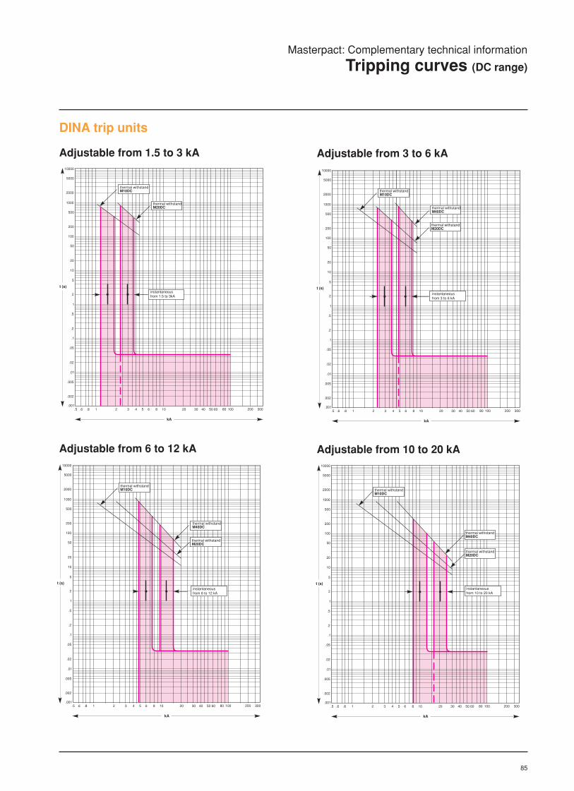
85
Masterpact: Complementary technical information
Tripping curves (DC range)
Adjustable from 1.5 to 3 kA
Adjustable from 6 to 12 kA Adjustable from 10 to 20 kA
DINA trip units
Adjustable from 3 to 6 kA
1 2 3 4.5 .6 .8 5 10 20 30 406 8 50 60 80 100 300200
kA
.001
.002
.005
t (s)
.01
.02
.05
.1
.2
.5
1
2
5
10
20
50
100
200
500
1000
2000
5000
10000
thermal withstandM40DC
instantaneousfrom 6 to 12 kA
thermal withstandM10DC
thermal withstandM20DC
1 2 3 4.5 .6 .8 5 10 20 30 406 8 50 60 80 100 300200
kA
.001
.002
.005
t (s)
.01
.02
.05
.1
.2
.5
1
2
5
10
20
50
100
200
500
1000
2000
5000
10000
thermal withstandM40DC
instantaneousfrom 10 to 20 kA
thermal withstandM10DC
thermal withstandM20DC
1 2 3 4.5 .6 .8 5 10 20 30 406 8 50 60 80 100 300200
kA
.001
.002
.005
t (s)
.01
.02
.05
.1
.2
.5
1
2
5
10
20
50
100
200
500
1000
2000
5000
10000
thermal withstandM40DC
instantaneousfrom 3 to 6 kA
thermal withstandM10DC
thermal withstandM20DC
1 2 3 4.5 .6 .8 5 10 20 30 406 8 50 60 80 100 300200
kA
.001
.002
.005
t (s)
.01
.02
.05
.1
.2
.5
1
2
5
10
20
50
100
200
500
1000
2000
5000
10000
instantaneousfrom 1.5 to 3kA
thermal withstandM10DC
thermal withstandM20DC

86
Adjustable from 20 to 40 kA
Adjustable from 12 to 24 kAAdjustable from 9 to 18 kA
1 2 3 4.5 .6 .8 5 10 20 30 406 8 50 60 80 100 300200
kA
.001
.002
.005
t (s)
.01
.02
.05
.1
.2
.5
1
2
5
10
20
50
100
200
500
1000
2000
5000
10000
thermal withstandM60DC
instantaneousfrom 9 to 18 kA
thermal withstandM80DC
1 2 3 4.5 .6 .8 5 10 20 30 406 8 50 60 80 100 300200
kA
.001
.002
.005
t (s)
.01
.02
.05
.1
.2
.5
1
2
5
10
20
50
100
200
500
1000
2000
5000
10000
thermal withstandM60DC
instantaneousfrom 12 to 24 kA
thermal withstandM80DC
1 2 3 4.5 .6 .8 5 10 20 30 406 8 50 60 80 100 300200
kA
.001
.002
.005
t (s)
.01
.02
.05
.1
.2
.5
1
2
5
10
20
50
100
200
500
1000
2000
5000
10000
thermal withstandM60DC
instantaneousfrom 20 to 40 kA
thermal withstandM80DC
Masterpact: Complementary technical information
Tripping curves (DC range)

87
Masterpact: Complementary technical information
Effect of ambient temperature (DC range)
The tables below indicate derating values forMasterpact DC circuit breakers dependingon the ambient temperature around thedevice.
Fixed circuit breaker: maximum operational current (A)Masterpact M10DC M20DC M40DCType D, E, F, H, J D, E, F, H, J D E, F H Jamb. temp. (°C) 40 1000 2000 4000 4000 3600 3500
45 1000 2000 4000 3860 3450 336050 1000 2000 3900 3750 3280 320055 1000 2000 3780 3630 3110 304060 1000 2000 3660 3520 2940 286065 1000 2000 3530 3400 2760 2690
Drawout circuit breaker: maximum operational current (A)Masterpact M10DC M20DC M40DC M60DC M80DCType D, E, F, H, J D, E, F, H, J D E, F H J G Gamb. temp. (°C) 40 1000 2000 4000 4000 3600 3500 6000 8000
45 1000 2000 4000 3860 3450 3360 6000 800050 1000 2000 3900 3750 3280 3200 6000 800055 1000 2000 3780 3630 3110 3040 6000 800060 1000 2000 3660 3520 2940 2860 6000 800065 1000 2000 3530 3400 2760 2690 6000 8000

88

89
7
LV air circuit breakersand switch-disconnectors
Masterpact80 to 6300 Amp
Installation and connectiondetails
page
Installation details General 90
Safety clearances (AC range) 91
Safety clearances (DC range) 92
Manual source changeover
systems 93
Manual & auto changeover
systems 94
Connection details General 95
AC range Fixed & drawout M08 to M16 98
Fixed & drawout M20 to M25 99
Fixed & drawout M20 to M32 100
Fixed & drawout M40 101
Fixed & drawout M50 to M63 103
DC range Types of DC distribution systems 105
General 106
Fixed M10 to M20 108
Fixed M40 110
Drawnout M10 to M20 111
Drawnout M40 113
Drawnout M60/80 115
Section 7

90
Installation on rails Installation on a metal base plate
30526
45
Masterpact: Installation details
General
Installation Masterpact circuit breakers must be installedin the vertical position on a base plate or onrails.
Fixed circuit breaker (M08 to M50)
Drawout circuit breaker(M08 to M63)
The drawout version makes it possible to:c Rapidly remove and/or replace the circuit
breaker without having to disconnect themain busbar connections.
c Install spare outgoing ways in aswitchboard that will then be suitable toreceive the necessary circuitbreakers at a later date withoutmodification.
"Connected" position "Test" positionample clearance between contacts
"Disconnected" positioneasy withdrawal, short travel
"Withdrawn" positioncompact dimensions

91
Certain distances must be maintainedbetween a circuit breaker and otherelements such as earthed metal, busbarsand other circuit breakers. Taken together,these distances form the safety clearance forthe circuit breaker. The diagrams and thetable below indicate the required distanceswhen installing Masterpact circuit breakers.
These distances are the results of testscarried out in accordance with standardIEC 947-2 and are in part determined by theultimate breaking capacities.
Masterpact M08 to M50Type of connection to insulated barrier to metal parts To live bars
A B C D (2) A B C D (2) A B C D (2)Front connection without cover (1) 360 30 0 0 360 70 – 0 1085 420 – 0Rear connection without cover 150 30 20 0 250 70 95 0 1085 420 495 0Rear connection with cover 0 0 20 0 0 0 95 – 145 105 125 0
Drawout circuit breaker
(1) Shield compulsary with front connections.(2) D is the clearance required for connection of
auxiliaries.D = 0 for fixed circuit breakers (required
clearance included in the height of theconnection plugs).
D = 0 for drawout circuit breakers as well.
Masterpact: Installation details
Safety clearance (AC range)
Note: For the fixed circuit breakers, a clearance of130 mm is required on top for removal of the arcchutes.
Fixed circuit breaker
A
C100
D
B
A
B
A
B B
A
C100
D
C100
213
A
B
A
B
Masterpact M08 to M63Type of connection To insulated barrier To metal parts To live bars
A B C A B C A B CFront connection without cover (1) 300 15 0 300 50 – 1000 400 –Rear connection without cover 150 15 45 150 50 45 1000 400 445Rear connection with cover 0 0 45 0 0 45 60 85 75

92
To insulated barrier To metal parts
Version distance (mm) A B C A B C
Fixed 0 0 20 0 0 95
Drawout 0 0 45 0 0 45
Masterpact: Installation details
Safety clearance (DC range)
C100
213
439
A
A
B B
Certain distances must be maintainedbetween a circuit breaker and otherelements such as earthed metal, busbarsand other circuit breakers. Taken together,these distances form the safety clearancefor the circuit breaker. The diagrams and thetable below indicate the required distanceswhen installing Masterpact DC circuitbreakers. These distances are the results oftests carried out in accordance withstandardIEC 947-2 and are in part determined by theultimate breaking capacities.
404
A
CFixed circuit breaker
Drawout circuit breaker
B
A
B

93
Masterpact: Installation details
Source-changeover system
Interlocking by connecting rods for 2 stack-mounted breakersdrawout pattern, 3 or 4 poles
Fixed pattern, 3 or 4 poles
Fixed pattern, 3 or 4 poles
Interlocking by connecting rods for 3 stack-mounted breakersdrawout pattern, 3 or 4 poles
base of c.b.for ratings :M08 to M40 (3p)
base of c.b.for ratings :M40 (4p) to M63 (*)
3052
82
40
125
50
153
163 (*)
65
166
45
900max.
900max.
base of c.b.
5
125
50
175
105(*)
30
18030 mini60 maxi
900max.
3014
(*)
44
base of c.b.for ratings :M08 to M40 (3p)
base of c.b. for ratings :M40 (4p) to M63
6052
100
40180
50
153
163 (*)
65
166
45
900max.
900max.
40180
50
900max.
6052
base of c.b.
5
180
175
105(*)
30
18030 mini60 maxi
900max.
6014
(*)
62
50
5
180
900max.
6014

94
Masterpact: Installation details
Manual and automatic source changeover systems
Manual source changeover systemInterlocking by cables for 2 side-by-side breakersfixed or drawout patterns 3 or 4 poles
(*) Datum
2m maxi
200 mini
r= 120 mini r= 120 mini
Automatic source changeover systemMounted on frame
600
AIS
56 56
150
940
1640
1940
2100
750
56 56
AIS
M32(3p)
M32(4p)M40(3p)
BA or UA BA/UA
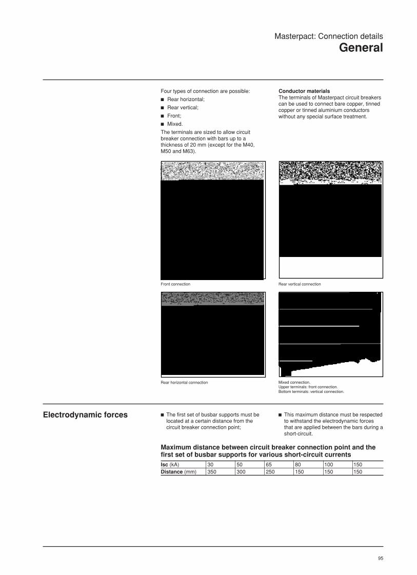
95
Rear horizontal connection Mixed connection.Upper terminals: front connection.Bottom terminals: vertical connection.
Rear vertical connectionFront connection
Masterpact: Connection details
General
Four types of connection are possible:
c Rear horizontal;
c Rear vertical;
c Front;
c Mixed.
The terminals are sized to allow circuitbreaker connection with bars up to athickness of 20 mm (except for the M40,M50 and M63).
Conductor materialsThe terminals of Masterpact circuit breakerscan be used to connect bare copper, tinnedcopper or tinned aluminium conductorswithout any special surface treatment.
Electrodynamic forces c The first set of busbar supports must belocated at a certain distance from thecircuit breaker connection point;
c This maximum distance must be respectedto withstand the electrodynamic forcesthat are applied between the bars during ashort-circuit.
Maximum distance between circuit breaker connection point and thefirst set of busbar supports for various short-circuit currentsIsc (kA) 30 50 65 80 100 150Distance (mm) 350 300 250 150 150 150

96
Masterpact: Connection details
General
Example Data:c Drawout circuit breaker;
c Flat busbars;
c Temperature: Ta
= 50 °C;
c Operating current: 1800 A.
Solution:For T
a= 50 °C; table 2 indicates an M20
circuit breaker connected either with three80 x 5 mm bars or two 63 x 10 mm bars.
Connection selection table Note:
The indicated values come from tests andtheoretical calculations made for theparameters given below. These tables are
Parameters used inestablishing the tables
c Maximum admissible bartemperature: 100 °C;
c Temperature in the switchboard aroundthe circuit breaker and its connections: Ta;
c Copper busbars.
intended to serve as a general guide forconnection design and not to replaceexperience acquired for a certain type ofconnection or the need for subsequent tests.
Drawout circuit breakers
drawout circuit breakers, edgewise barsMaximum Ta = 40 °C Ta = 50 °C Ta = 60°Ccurrent
Masterpact Number of bars Masterpact Number of bars Masterpact Number of bars5 thick bars 10 thick bars 5 thick bars 10 thick bars 5 thick bars 10 thick bars
800 M08 2b.50 x 5 1b.50 x 10 M08 2b.50 x 5 1b.50 x 10 M08 2b.50 x 5 1b.50 x 101000 M10 2b.50 x 5 1b.50 x 10 M10 2b.50 x 5 1b.50 x 10 M10 2b.63 x 5 1b.63 x 101250 M12 2b.63 x 5 1b.63 x 10 M12 2b.63 x 5 1b.63 x 10 M12 3b.50 x 5 2b.50 x 101400 M16 2b.63 x 5 1b.63 x 10 M16 2b.63 x 5 1b.63 x 10 M16 3b.50 x 5 2b.50 x 101600 M16 2b.80 x 5 1b.80 x 10 M16 2b.80 x 5 1b.80 x 10 M20 3b.63 x 5 2b.50 x 101800 M20 2b.80 x 5 1b.80 x 10 M20 2b.80 x 5 2b.50 x 10 M20 3b.80 x 5 2b.63 x 102000 M20 2b.100 x 5 2b.63 x 10 M20 2b.100 x 5 2b.63 x 10 M25 3b.100 x 5 2b.80 x 102200 M25 2b.100 x 5 2b.63 x 10 M25 2b.100 x 5 2b.63 x 10 M25 3b.100 x 5 2b.80 x 102500 M25 4b.80 x 5 2b.80 x 10 M25 4b.80 x 5 2b.80 x 10 M32 4b.100 x 5 3b.80 x 102800 M32 4b.100 x 5 2b.100 x 10 M32 4b.100 x 5 2b.100 x 10 M32 4b.100 x 5 3b.80 x 103000 M32 5b.100 x 5 3b.80 x 10 M32 6b.100 x 5 3b.100 x 10 M40 3b.100 x 103200 M32 6b.100 x 5 3b.100 x 10 M40 3b.100 x 10 M40 4b.100 x 103600 M40 4b.100 x 10 M40 4b.100 x 10 M50 4b.100 x 104000 M40 4b.100 x 10 M50 4b.100 x 10 M50 5b.100 x 104700 M50 5b.100 x 10 M50 5b.100 x 10 M50 5b.100 x 105000 M50 5b.100 x 10 M50 5b.100 x 10 M63 6b.100 x 105100 M63 5b.100 x 10 M63 6b.100 x 10 M63 6b.100 x 105700 M63 6b.100 x 10 M63 6b.100 x 106300 M63 6b.100 x 10
Fixed circuit breakers
Fixed circuit breakers, edgewise barsMaximum Ta = 40 °C Ta = 50 °C Ta = 60°Ccurrent
Masterpact Number of bars Masterpact Number of bars Masterpact Number of bars5 thick bars 10 thick bars 5 thick bars 10 thick bars 5 thick bars 10 thick bars
800 M08 2b.50 x 5 1b.50 x 10 M08 2b.50 x 5 1b.50 x 10 M08 2b.50 x 5 1b.50 x 101000 M10 2b.50 x 5 1b.50 x 10 M10 2b.50 x 5 1b.50 x 10 M10 2b.63 x 5 1b.63 x 101250 M12 2b.63 x 5 1b.63 x 10 M12 2b.63 x 5 1b.63 x 10 M12 3b.50 x 5 2b.50 x 101400 M16 2b.63 x 5 1b.63 x 10 M16 2b.63 x 5 1b.63 x 10 M16 3b.50 x 5 2b.50 x 101600 M16 2b.80 x 5 1b.80 x 10 M16 2b.80 x 5 1b.80 x 10 M16 3b.63 x 5 2b.50 x 101800 M20 2b.80 x 5 1b.80 x 10 M20 2b.80 x 5 2b.50 x 10 M20 3b.80 x 5 2b.63 x 102000 M20 2b.100 x 5 2b.63 x 10 M20 2b.100 x 5 2b.63 x 10 M20 3b.100 x 5 2b.80 x 102200 M25 2b.100 x 5 2b.63 x 10 M25 2b.100 x 5 2b.63 x 10 M25 3b.100 x 5 2b.80 x 102500 M25 4b.80 x 5 2b.80 x 10 M25 4b.80 x 5 2b.80 x 10 M25 4b.100 x 5 3b.80 x 102800 M32 4b.100 x 5 2b.100 x 10 M32 4b.100 x 5 2b.100 x 10 M32 4b.100 x 5 3b.80 x 103000 M32 5b.100 x 5 3b.80 x 10 M32 6b.100 x 5 3b.100 x 10 M32 4b.80 x 103200 M32 6b.100 x 5 3b.100 x 10 M32 6b.100 x 5 3b.100 x 10 M40 4b.100 x 103600 M40 4b.100 x 10 M40 4b.100 x 10 M40 4b.100 x 104000 M40 4b.100 x 10 M40 4b.100 x 10 M50 5b.100 x 104500 M50 5b.100 x 10 M50 5b.100 x 10 M50 5b.100 x 105000 M50 5b.100 x 10 M50 5b.100 x 10 M50 6b.100 x 10

97
Fixed circuit breakers, flat barsMaximum Ta = 40 °C Ta = 50 °C Ta = 60°Ccurrent
Masterpact Number of bars Masterpact Number of bars Masterpact Number of bars5 thick bars 10 thick bars 5 thick bars 10 thick bars 5 thick bars 10 thick bars
800 M08 2b.50 x 5 1b.50 x 10 M08 2b.50 x 5 1b.50 x 10 M08 2b.50 x 5 2b.50 x 101000 M10 3b.50 x 5 1b.63 x 10 M10 3b.50 x 5 2b.50 x 10 M10 3b.63 x 5 2b.50 x 101250 M12 3b.50 x 5 2b.40 x 10 M12 3b.50 x 5 2b.40 x 10 M12 3b.63 x 5 2b.50 x 101250 M12 2b.80 x 5 2b.40 x 10 M12 2b.80 x 5 2b.40 x 101400 M16 3b.50 x 5 2b.40 x 10 M16 2b.80 x 5 2b.50 x 10 M16 3b.80 x 5 2b.63 x 101600 M16 3b.63 x 5 2b.50 x 10 M16 3b.80 x 5 2b.63 x 10 M16 3b.80x 5 3b.50 x 101800 M20 3b.80 x 5 2b.63 x 10 M20 3b.80 x 5 2b.63 x 10 M20 3b.100 x 5 2b.80 x 102000 M20 3b.100 x 5 2b.80 x 10 M20 3b.100 x 5 2b.80 x 10 M20 3b.100 x 5 3b.63 x 102200 M25 3b.100 x 5 2b.80 x 10 M25 3b.100 x 5 2b.80 x 10 M25 4b.80 x 5 2b.100 x 102500 M25 4b.100 x 5 2b.100 x 10 M25 4b.100 x 5 2b.100 x 10 M25 4b.100 x 5 3b.80 x 102800 M32 4b.100 x 5 3b.80 x 10 M32 4b.100 x 5 3b.80 x 10 M32 5b.100 x 5 3b.100 x 103000 M32 5b.100 x 5 3b.80 x 10 M32 6b.100 x 5 3b.100 x 10 M32 8b.100 x 5 4b.80 x 103200 M32 6b.100 x 5 3b.100 x 10 M32 8b.100 x 5 3b.100 x 10 M40 4b.100 x 103800 M40 4b.100 x 10 M40 5b.100 x 10 M40 5b.100 x 104000 M40 5b.100 x 10 M40 5b.100 x 10 M50 5b.100 x 104500 M50 5b.100 x 10 M50 5b.100 x 10 M50 5b.100 x 105000 M50 5b.100 x 10 M50 5b.100 x 10
Masterpact: Connection details
General
Drawout circuit breakers
Drawout circuit breakers, flat barsMaximum Ta = 40 °C Ta = 50 °C Ta = 60°Ccurrent
Masterpact Number of bars Masterpact Number of bars Masterpact Number of bars5 thick bars 10 thick bars 5 thick bars 10 thick bars 5 thick bars 10 thick bars
800 M08 2b.50 x 5 1b.50 x 10 M08 2b.50 x 5 1b.50 x 10 M08 2b.50 x 5 2b.50 x 101000 M10 3b.50 x 5 1b.63 x 10 M10 3b.50 x 5 2b.50 x 10 M10 3b.63 x 5 2b.50 x 101250 M12 3b.50 x 5 2b.50 x 10 M12 3b.50 x 5 2b.50 x 10 M12 (1) 3b.63 x 5 2b.50 x 101250 M12 2b.80 x 5 2b.50 x 10 M12 2b.80 x 5 2b.50 x 10 M16 3b.63 x 5 2b.50 x 101400 M16 3b.50 x 5 2b.50 x 10 M16 2b.80 x 5 2b.50 x 10 M16 3b.80 x 5 2b.63 x 101600 M16 3b.63 x 5 2b.50 x 10 M16 3b.80 x 5 2b.63 x 10 M20 3b.80 x 5 3b.50 x 101800 M20 3b.80 x 5 2b.63 x 10 M20 3b.80 x 5 2b.63 x 10 M20 3b.100 x 5 2b.80 x 102000 M20 3b.100 x 5 2b.80 x 10 M20 3b.100 x 5 2b.80 x 10 M25 3b.100 x 5 3b.63 x 102200 M25 3b.100 x 5 2b.80 x 10 M25 3b.100 x 5 2b.80 x 10 M25 (2) 4b.80 x 5 2b.100 x 102500 M25 4b.100 x 5 2b.100 x 10 M32 4b.100 x 5 2b.100 x 10 M32 4b.100 x 5 3b.80 x 102800 M32 4b.100 x 5 3b.80 x 10 M32 4b.100 x 5 3b.80 x 10 M32 5b.100 x 5 3b.100 x 103000 M32 5b.100 x 5 3b.80 x 10 M32 6b.100 x 5 3b.100 x 10 M40 8b.100 x 5 3b.100 x 103100/3150 M32 6b.100 x 5 3b.100 x 10 M40 8b.100 x 5 3b.100 x 10 M40 10b.100 x 5 4b.100 x 103500 M40 8b.100 x 5 4b.100 x 10 M40 8b.100 x 5 4b.100 x 10 M50 10b.100 x 5 5b.100 x 103800 M40 8b.100 x 5 4b.100 x 10 M50 10b.100 x 5 5b.100 x 10 M50 10b.100 x 5 5b.100 x 104000 M50 10b.100 x 5 5b.100 x 10 M50 10b.100 x 5 5b.100 x 10 M50 10b.125 x 5 5b.100 x 104500 M50 10b.100 x 5 5b.100 x 10 M50 10b.100 x 5 5b.100 x 10 M63 10b.125 x 5 6b.100 x 104800 M50 10b.100 x 5 5b.100 x 10 M63 10b.125 x 5 6b.100 x 10 M63 10b.125 x 5 6b.100 x 105000 M50 10b.100 x 5 5b.100 x 10 M63 10b.125 x 5 6b.100 x 105400 M63 10b.125 x 5 6b.100 x 10 M63 10b.125 x 5 6b.100 x 106000 M63 10b.125 x 5 6b.100 x 10(1) Except for M12N.(2) Except for M25L.
Fixed circuit breakers

98
Fixed circuit breakerFront connection Rear connection
horizontal terminals vertical terminalsFront connection
Rear connectionHorizontal terminals
Vertical terminals
Masterpact: Connection details
Fixed and drawout circuit breakers (AC range)
M08H,L/M10H,L/M12H,L/M16,H,L
Drawout circuit breakerFront connection Rear connection
Horizontal terminals vertical terminals
Front connection
306
12,5
30
12,510
273
25
300,5
12,5
306
1512,5
112
10
9215
25 112
57
80
175
25
(*)
front connectors screen
Rear connectionhorizontal terminals
Vertical terminals
10
47,5115115115
(*)
3 Ø12
1525
80
47,5115115115
(*)
N(1)
3 Ø12
25
(*) Datum.
(**) Hole for securing front connection support bracket.
(1) On request, neutral on the right.
(*) Datum.
(1) On request, neutral on the right.
10
85115115115
(*)2 Ø12
15
80
85115115115
(*)3 Ø12
2525
1525
80
85115115115
(*)
N(1)
3 Ø12
25
15
80
47,5115115115
(*)3 Ø12
2525
175 (**)
221 12,5
10
107
335
12,5
233
15 17
53
112
10
278 12,5
17,5
12,5
25
23
132
50
(*)
front connectors screen

99
Fixed circuit breakerFront connection Rear connection
Horizontal terminals vertical terminalsFront connection
Rear connectionHorizontal terminals
Vertical terminals
Masterpact: Connection details
Fixed and drawout circuit breakers (AC range)
M20,H/M25,H
Drawout circuit breakerFront connection Rear connection
horizontal terminals vertical terminals
Front connection
306
12,5
30
12,520
273
25
300,5
12,5
306
1512,5
112
20
9215
25 112
62
80
175
25
(*)
front connectors screen
Rear connectionHorizontal terminals
Vertical terminals
1525
80
47,5115115115
(*)
N(1)
3 Ø12
25
(*) Datum.
(**) Hole for securing front connection support bracket.
(1) On request, neutral on the right.
(*) Datum.
(1) On request, neutral on the right.
20
85115115115
(*)3 Ø12
15
80
85115115115
(*)3 Ø12
2525
1525
80
85115115115
(*)
N(1)
3 Ø12
25
15
80
47,5115115115
(*)3 Ø12
2525
16
47,5115115115
(*)
3 Ø12
175 (**)
221 12,5
16
107
335
12,5
233
15 18
53
112
20
283
17,515
25
3
152
80
(*)
25
12,5
front connectors screen

100
Drawout circuit breakerFront connection Rear connection
Horizontal terminals Vertical terminalsFront connection
Rear connectionHorizontal terminals
Vertical terminals
12,525
37,5125125125
(*)
N(1)
4 Ø12
2525
100
363
15
37
1530
329
344 15
92
112
30
(*)
344 15
25
12,5
2525
34,5
157
100
front connectors sceen
10152,5152,5115
(*)4 Ø12
25
12,525
37,5125125115
(*)4 Ø12
2525
100
Fixed circuit breakerFront connection Rear connection
Horizontal terminals Vertical terminals
Front connection
Rear connectionHorizontal terminals
Vertical terminals
Masterpact: Connection details
Fixed and drawout circuit breakers (AC range)
M20L/M25L/M32H
11,5
85,5
72,5115140115
(*)3 Ø12
2525
1525
80
85115115115
(*)
N(1)
3 Ø12
25
60140140115
(*)4 Ø12
25
175 (**)
221 1530
87
335
15
236
18 15
53
112
30
268
18
12,5
25
7
162
100
(*)
25
15
25
front connectors screen
(*) Datum.
(**) Hole for securing front connection support bracket.
(1) On request, neutral on the right.

101
Fixed circuit breakerRear connection 3 or 4 polesHorizontal terminals Vertical terminals
Masterpact: Connection details
Fixed and drawout circuit breaker (AC range)
M40
243
112
15(*)
53
30
25
306
55
15
12,5
252525
252
100
(*) Datum.
Drawout circuit breakerRear connection 3 or 4 polesHorizontal terminals Vertical terminals
92
15
175
345
(*)
363
137
112
30
15
34,5(3p)
12,5
252525
79,5(4p)
157
100
(*) Datum.
Continued on following page

102
N(1)
(*)Ø12
65155
100 155
4025 25 2525252512,5
191
155155
230
Fixed circuit breakerRear connection 3 polesHorizontal terminals Vertical terminals
10
(*)
Ø12
10
35
85
80
145
172,5172,5
80100
12,525 25 2512,5
25 25 25
130
165
(*)
85180
Ø12
100
Rear connection 4 polesHorizontal terminals Vertical terminals
10
(*)
Ø12
10
35
85
80
145
172,5208,5
8080
230
N(1)
100
12,525 25 2512,5
25 25 25
130
165
(*)
85216
Ø12
100100
230
N(1)
(*) Datum.
(1) On request, neutral on the right.
Drawout circuit breakerRear connection 3 polesHorizontal terminals Vertical terminals
Rear connection 4 polesHorizontal terminals Vertical terminals
(*) Datum.
(1) On request, neutral on the right.
4025 25 2525252512,5
100 155
65
(*)
155155
Ø12
10 10
35
47,5
(*)
Ø12
172,5172,5
70
10 10
35
47,5
(*)
Ø12
172,5208,5
70
230
N(1)
Masterpact: Connection details
Fixed and drawout circuit breaker (AC range)
M40 (cont.)

103
Fixed circuit breaker M50Rear connection 3 polesHorizontal terminals Vertical terminals
Masterpact: Connection details
Fixed and drawout circuit breaker (AC range)
M50 to M63
246
112
15(*)
53
30
25
306
55
1512,5
252525
52
100
200
Drawout circuit breaker M50Rear connection 3 or 4 polesHorizontal terminals Vertical terminals
92
15
25
345
(*)
363
137
112
30
15
12,5
252525
79,5
157
100
43
Drawout circuit breaker M63Rear connection 3 or 4 polesHorizontal terminals Vertical terminals
92
15
25
345
(*)
363
137
112
30
15
12,5
252525
79,5
157
100
43
(*) Datum.
Continued on following page

104
Fixed circuit breaker M50Rear connection 3 polesHorizontal terminals Vertical terminals
(*) Datum.
(1) On request, neutral on the right.
10
(*)
Ø12 10
35
142,5
145175
248248
145(*)Ø12
252525
226 213
142,5
20
248
1320
248
213
Drawout circuit breaker M50Rear connection 3 polesHorizontal terminals Vertical terminals
10
(*)
Ø12 10
72,5
100252,5252,5
145
25 25 2525 25 25 45
220
100
(*)
252,5252,5
Ø12
12,5
Rear connection 4 polesHorizontal terminals Vertical terminals
25 25 2525 25 25 45
220
100
(*)
245245
Ø12
12,5
297,5
100
25 25 25 12,5
N(1)
10
(*)
Ø12
N(1)
10
72,5
100245245297,5
35
14570
10 10
Drawout circuit breaker M63Rear connection 3 polesHorizontal terminals Vertical terminals
10
(*)
Ø12 10
92,5
117,5350350
185
25 25 2525 25 25 85
260
117,5
(*)
350350
Ø12
10
(*)
Ø12
N(1)
10
92,5
117,5287287206
35
18570
25 25 2525 25 25 85
260
117,5
(*)
260
287287
260100
25 25 25
206
Ø12N(1)
Rear connection 4 polesHorizontal terminals Vertical terminals
Masterpact: Connection details
Fixed and drawout circuit breaker (AC range)
M50 to M63 (cont.)

105
+
–
U/2
B A
C
charge
iaaaaaaaaaU/2
+
–
U
B A
C
i
chargeaaaaaaaaa+
–aaaaaaaaacharge
B A
U
i
Masterpact: Connection details
Types of DC distribution systems (DC range)
selection of a DCcircuit breaker
There are three types of DC distributionsystems. Selection of an operational voltagewith one of the three types of distributionsystems determines the number of polesrequired for breaking.
Selection of a DC circuit breaker dependson the following criteria:c The type of DC distribution system, which
determines the required version;c The rated current, which determines the
circuit-breaker rating;c The rated voltage, which determines the
number of in-series poles required forbreaking;
c The maximum short-circuit current at thepoint of installation, which determines thebreaking capacity of the circuit breaker.
The negative polarity of thesource is earthedFault AIsc maximum.The positive polarity of the breaker isinvolved in clearing the fault
Fault BIsc maximum.The 2 polarities of the breaker are involvedin clearing the fault.
Distribution system n° 1: isolated
Distribution system n° 2: earthed middlepoint
Distribution system n° 3: earthed negativepolarity
1st alternative
2nd alternative
+
–aaaaaaaaacharge
A
The source is isolatedfrom earthFault BIsc maximum.The 2 polarities of the breaker are involvedin clearing the fault.
Fault A or CNo consequence.
Simultaneous faults A and CIsc < Isc max.(due to earth-loop impedance).The 2 polarities of the breaker are involvedin clearing the fault.
The middle point of thesource is earthedFault BIsc maximum (at U).The 2 polarities of the breaker are involvedin clearing the fault.
Fault A or CIsc < Isc maximum at U/2.The positive or negative polarity of thebreaker is involved in clearing the fault.
Simultaneous faults A and CIsc < Isc max.(due to earth-loop impedance).The 2 polarities of the breaker are involvedin clearing the fault.
Most unfavourable faultFault BIsc maximum.Distribute the poles between the twopolarities.
Most unfavourable faultFault A or CEach polarity (positive or negative) can beconcerned by the fault at U/2.
Most unfavourable faultFault AIsc maximum on single polarity.All the poles must be connected in series onthe positive polarity.In this case, an extra pole provided on thenegative polarity has only an isolatingfunction.
The source and the loadare earthedOne type of fault (A):all the poles must be associated in series onthe positive polarity.
load
load
load
load
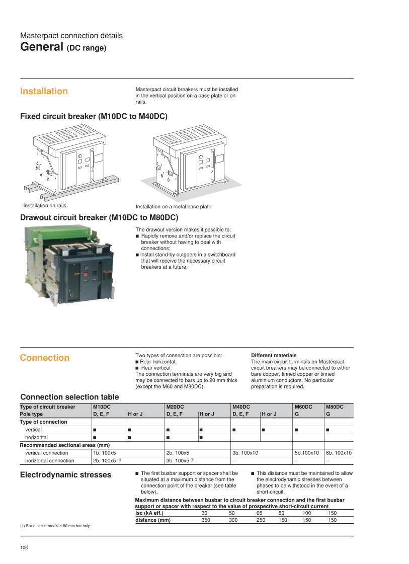
106
Masterpact connection details
General (DC range)
Masterpact circuit breakers must be installedin the vertical position on a base plate or onrails.
Installation
Fixed circuit breaker (M10DC to M40DC)
Installation on a metal base plateInstallation on rails
The drawout version makes it possible to:c Rapidly remove and/or replace the circuit
breaker without having to deal withconnections;
c Install stand-by outgoers in a switchboardthat will receive the necessary circuitbreakers at a future.
Two types of connection are possible:c Rear horizontal;c Rear vertical.The connection terminals are very big andmay be connected to bars up to 20 mm thick(except the M60 and M80DC).
Different materialsThe main circuit terminals on Masterpactcircuit breakers may be connected to eitherbare copper, tinned copper or tinnedaluminium conductors. No particularpreparation is required.
Connection
Drawout circuit breaker (M10DC to M80DC)
Connection selection tableType of circuit breaker M10DC M20DC M40DC M60DC M80DCPole type D, E, F H or J D, E, F H or J D, E, F H or J G G
Type of connection
vertical c c c c c c c chorizontal c c c c
Recommended sectional areas (mm)
vertical connection 1b. 100x5 2b. 100x5 3b. 100x10 5b.100x10 6b. 100x10
horizontal connection 2b. 100x5 (1) 3b. 100x5 (1) - - -
Maximum distance between busbar to circuit breaker connection and the first busbarsupport or spacer with respect to the value of prospective short-circuit currentIsc (kA eff.) 30 50 65 80 100 150distance (mm) 350 300 250 150 150 150
c This distance must be maintained to allowthe electrodynamic stresses betweenphases to be withstood in the event of ashort-circuit.
c The first busbar support or spacer shall besituated at a maximum distance from theconnection point of the breaker (see tablebelow).
Electrodynamic stresses
(1) Fixed circuit breaker: 80 mm bar only.

107
Selection of pole-connection types dependson the type of distribution system and theoperational voltage.The Masterpact DC range offers sixdifferent pole-connection types, namely D,E, F, G, H and J.The selected type must be mentioned onthe order form.
The series connections for the selected poletype are delivered with the circuit breaker.All Masterpact DC circuit breakers are thussupplied ready for connection.
Note : front view diagrams.
load
charge
+ –
charge
+ –
charge
+
–
Selection table
Type F:4-pole breaker
Type E:4-pole breakerU > 750 V: mandatory supply via upperterminals
Type D:3-pole breaker
Type H:3-pole breaker
Version J:4-pole breaker
Type G:2-pole breaker
charge
+ –
charge
+
–
load load
load load load
charge
+ –
load
Circuit breaker identification M10-20-40DC M60-80DCRated current (A) 1000-2000-4000 6000-8000Operational voltage (V) 250/500 750 1000 250Distribution system n° 1: isolated D E E GDistribution system n° 2: earthed middle point D E E GDistribution system n° 3: earthed negative polarity
c Alternative n° 1 D F - Gc Alternative n° 2 H H J G
Masterpact: Connection details
Terminal configuration (DC range)

108
15
236 85
268
15
32
252525
12,5 4
100
158
53
(*)
112
30
56
Masterpact: Connection details
Fixed Masterpact M10/20DC (DC range)
Types D, E and FHorizontal connection Vertical connection
Rear view
(*)
25
72,5 115 140
25
3 Ø12
80
(*)
25
72,5 115 115140
25
3 Ø12
80
(*)
25
72,5 115 115140
25
3 Ø12
80
Type D Type E
(*)
25
60 140 115140
4 Ø12
(*)
25
60 140 115140
4 Ø12
(*)
25
60 140 140
4 Ø12
Type D Type E Type F
Type F
Horizontal connection
Vertical connection
(*) Datum

109
Type H Type J
Types H and JHorizontal connection Vertical connection
25
72,5 115 140
25
3 Ø12
80
(*)
(*)
25
72,5 115 115140
25
3 Ø12
80
Vertical connection
Rear viewHorizontal connection
25
60 140 140
4 Ø12
(*)
(*)
25
60 140 115140
4 Ø12
Type H Type J
15
236 85
268
32
100
158
53
112
30
56
12
252525
12,5
15
(*)
Masterpact: Connection details
Fixed Masterpact M10/20DC (DC range)
(*) Datum

110
Types H and JVertical connection
Rear view
(*)
25
60 140 140
4 Ø12
20,559
(*)
25
60 140 115140
4 Ø12
20,5 59Type H Type J
Vertical connection
252525
12,5 4
100
158
190268
1547
149(*)
1547
252525
12,5 4
100
158
190268
(*)
Vertical connection
Masterpact: Connection details
Fixed Masterpact M40DC (DC range)
Types D and FVertical connection
(*)
25
60 140 140
4 Ø12
20,559
(*)
25
60 140 115140
4 Ø12
20,5 59
Type E
(*)
25
60 140 115140
4 Ø12
20,5 59
Type FType D
Rear view
Type E
1547
252525
12,5 4
100
158
190268
(*)
(*) Datum
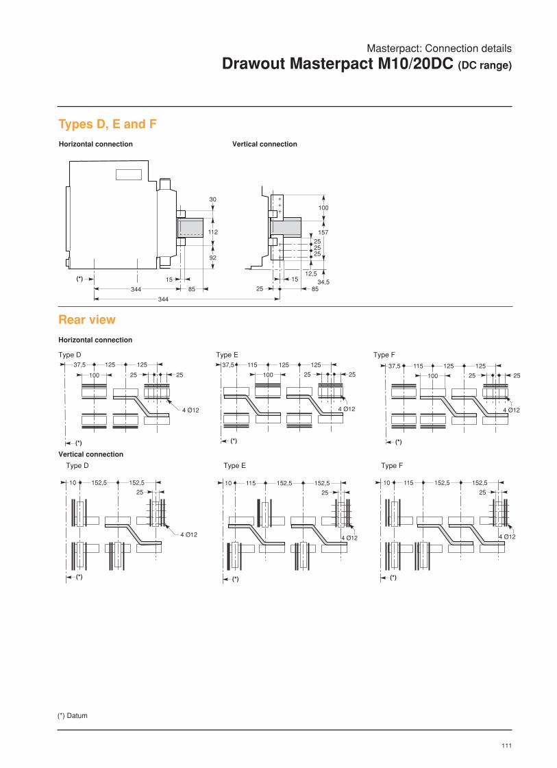
111
(*) 15
112
30
344
344
92
25
100
157
85
12,515
252525
34,585
Horizontal connection
Masterpact: Connection details
Drawout Masterpact M10/20DC (DC range)
Types D, E and FHorizontal connection Vertical connection
Rear view
(*)
25
37,5 125125
25
4 Ø12
100
(*)
25
37,5 115 125125
25
4 Ø12
100
(*)
25
37,5 115 125125
25
4 Ø12
100
Type D Type E Type F
Vertical connection
Type D Type E Type F
(*) Datum
(*)
25
10 152,5
4 Ø12
152,5
(*)
25
10 115 152,5
4 Ø12
152,5
(*)
25
10 115 152,5
4 Ø12
152,5

112
Types H and JHorizontal connection Vertical connection
(*) 15
112
30
12
344 85
344
92
25
100
157
85
12,515
252525
34,5
Rear view
Horizontal connection
(*)
25
37,5 125125
25
4 Ø12
100
(*)
25
37,5 115 125125
25
4 Ø12
100
Vertical connection
Type JType H
(*)
25
10 152,5
4 Ø12
152,5
(*)
25
10 115 152,5
4 Ø12
152,5
Type JType H
Masterpact: Connection details
Drawout Masterpact M10/20DC (DC range)
(*) Datum

113
Type D Type E Type F
252525
12,534,5
100
157
190
(*) 15
344
25
Masterpact: Connection details
Drawout Masterpact M40DC (DC range)
Types D, E and FVertical connection
(*)
25
10 152,5
4 Ø12
152,5
20,5
59
(*)
25
10 115 152,5
4 Ø12
152,5
20,5 59
(*)
25
10 115 152,5
4 Ø12
152,5
20,5 59
Rear viewVertical connection
* Datum

114
Vertical connection
252525
12,534,5
100
157
190
149
(*) 15
344
25
Types H and JVertical connection
Rear view
(*)
25
10 152,5
4 Ø12
152,5
20,5
59
(*)
25
10 115 152,5
4 Ø12
152,5
20,5 59
140
Type JType H
Masterpact: Connection details
Drawout Masterpact M40DC (DC range)
(*) Datum

115
(*)
145
97,5 245
4 Ø12
1010
72,5
45
Masterpact: Connection details DC range
Drawout Masterpact M60/80DC (DC range)
type GVertical connection
252525
12,5
34,5
100
157
(*)15362
Rear viewVertical connection
Type G
(*) Datum
116

117
LV air circuit breakersand switch-disconnectors
Masterpact80 to 6300 Amp
Dimensions
page
Fixed M08 to M32 118
Drawout M08 to M32 119
Fixed M40 120
Drawout M40 120
Fixed M50 122
Drawout M50 123
Drawout M63 124
Fixed (DC range) 125
Drawout (DC range) 126
Panel cut out 127
Source Changeover 128
Section 8
8Please note that all Masterpact dimensionsare available on disk suitable for CAD use(please cosult us)

118
Masterpact: Dimensions
Fixed circuit breakers M08 to M32 (AC range)
Dimensions3 or 4 poles
(*) Datum
90 130
311
45
6830 mini60 maxi
290
150
(*)
necessary space for removing the arc chutes(with or without arc chute cover)
1111 515
11 11
(*)
493
553
378
438
400
422 (3p)
537 (4p)
On rails
MountingOn a base plate
(*) Datum
150
30 mini60 maxi
150
30 mini60 maxi
Mounting detail
3 poles 4 polesA 150 150B 400 515
Cut-outsFront panel cut-outs Holes for escutcheon
Ø14
2 Ø11 x 6Ø11
B
A
152,5
148,5
6971,5
17,518018011 Ø5
14,5
325
(*)
37,580 mini
270
27
(*)
80 mini

119
Masterpact: Dimensions
Drawout circuit breaker M08 to M32 (AC range)
Dimensions3 or 4 poles
(*) Datum
Mounting detailOn railsMountingOn a base plate
3 poles 4 polesA 175 175B 325 425
Cut-outsFront panel cut-out
Ø14
2 Ø11 x 6Ø11
B
A
aaaaaaa (*)45
10160367
175 85
439
128
800mini
"disconnected" position
(*)
70 55425
5532555
435 (3p)
550 (4p)
175101 175101
Holes for escutcheon
325
55100 mini
100 mini
270
4719
ACB's side
ACB's basis
152,5
148,5
69
71,5
18,5
17,518018011 Ø5
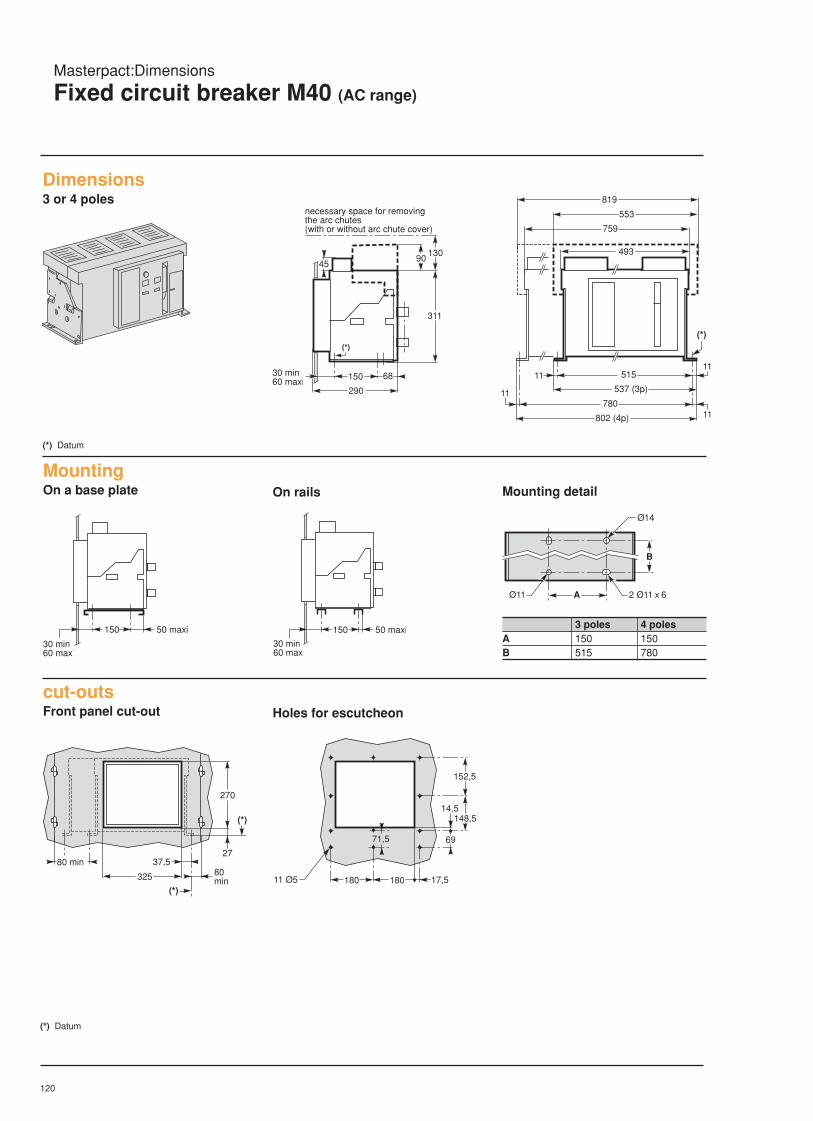
120
Masterpact:Dimensions
Fixed circuit breaker M40 (AC range)
(*) Datum
759
819
553
493
(*)
1111 515
537 (3p)
78011
11
802 (4p)
Dimensions3 or 4 poles
On rails
MountingOn a base plate Mounting detail
150
30 mini60 maxi
50 maxi 150
30 mini60 maxi
50 maxi
Ø14
2 Ø11 x 6Ø11
B
A
3 poles 4 polesA 150 150B 515 780
cut-outsFront panel cut-out
(*) Datum
90130
311
45
6830 mini60 maxi
290
150
(*)
necessary space for removing the arc chutes(with or without arc chute cover)
Holes for escutcheon
325
(*)
37,580 mini
270
27
(*)
80 mini
152,5
148,5
6971,5
17,518018011 Ø5
14,5

121
Masterpact: Dimensions
Drawout circuit breaker M40 (AC range)
Dimensions3 or 4 polesaaaaaaa (*)101
60
367
175 85
439
128
484
45
800mini
(1)
"disconnected" position
70 55425
60 350 55350
(*)
550 (3p)
815 (4p)
(*) Datum(1) 4-pole version only.
On rails
MountingOn a base plate Mounting detail
175101
(1)
175101
(1) 175 2 Ø11 x 6 (3p)6 Ø11 x 22 (4p)
350
350
150
40 40 30
(1) 4-pole version only.
Cut-outsFront panel cut-out
(1) 4-pole version only.
Holes for escutcheon
325
55100 mini
27047
19
45 (1)
ACB's side
ACB's basis
152,5
148,5
69
71,5
18,5
17,518018011 Ø5

122
Masterpact: Dimensions
Fixed circuit breaker M50 (AC range)
Dimensions3 poles
(*) Datum
90130
311
45
6830 mini60 maxi
290
150
(*)
necessary space for removing the arc chutes(with or without arc chute cover)
(*)
1111 780
802
759
819
(*) Datum
On rails
MountingOn a base plate Mounting detail
150
30 mini60 maxi
50 maxi 150
30 mini60 maxi
50 maxi
Ø14
2 Ø11 x 6Ø11
B
A
3 polesA 150B 780
Cut-outsFront panel cut-out Holes for escutcheon
152,5
148,5
6971,5
17,518018011 Ø5
14,5
325
(*)
37,580 mini
270
27
(*)
80 mini

123
Masterpact: Dimensions
Drawout circuit breaker M50 (AC range)
Dimensions3 or 4 poles
(*)
45
10160
367
175 85
128
484aaaaaaa 45
800mini
"disconnected" position
60 350 55350
(*)
815 (3p)
5547547540
1045 (4p)
(1) 4-pole version only.
(*) Datum
On rails
MountingOn a base plate Mounting detail
175101 175101
175 6 Ø11 x 22 (3p)6 Ø11 x 33 (4p)
350
350
150
40 40 30
Cut-outsFront panel cut-out Holes for escutcheon
325
55100 mini
27047
19
45 (1)
ACB's side
ACB's basis
152,5
148,5
69
71,5
18,5
17,518018011 Ø5

124
Masterpact: Dimensions
Drawout circuit breaker M63 (AC range)
Dimensions3 poles or 4 poles
40 475 55475
(*)1045
(*) Datum
On rails
MountingOn a plate Mounting detail
175101 175101
Cut-outsFront panel cut-out Holes for escutcheon
152,5
148,5
69
71,5
18,5
17,518018011 Ø5
175 6 Ø11 x 33
475
475
40 40 30
150
(*)
45
10160
367
175 85
128
484aaaaaaa800mini
45
"disconnected" position
325
55100 mini
27047
19
45 (1)
side of c.b.
base of c.b.

125
Masterpact: Dimensions
Fixed circuit breaker (DC range)
Types D and H Types E, F, G and J
40011 11
(*)
378
438
90 130
314
45
6830 mini60 maxi
290
150
(*)
515
11 11
(*)
493
553
Dimensions
On a base plate On rails
150
30 mini60 maxi
150
30 mini60 maxi
Mounting
Types E, F, and J Types D and H
A (mm) 150 150
B (mm) 515 400
Necessary space for removing the arcchutes
Ø14
A 2 Ø11 x 6
B
Ø11

126
(*)
position "débrochée"
45
800mini
10160
367
175 85 85
439
128aaaaaaaaaDimensionsTypes D and H Types E, F, G and J
(*)
55 55325(*)
70 55425
175101 175101
MountingOn a base plate On rails
disconnected position
Ø14
A 2 Ø11 x 6
B
Ø11
types E, F, G and J types D and H
A (mm) 175 175
B (mm) 425 325
Masterpact: Dimensions
Drawout circuit breaker (DC range)

127
Front panel cut-out (Fixed)
325
55100 mini
100 mini
base de l'appareil
270
côté appareil
47
19
Holes for escutcheon (Fixed)
152,5
148,5
69
71,5
18,5
17,518018011 Ø5
base of c.b.
side of c.b.
325
(*)
37,580mini
80mini
270
30
(*)
80 mini
71,5
152,5
148,5
69
14,5
17,518018011 Ø5
Front panel cut-out (Drawout)
Holes for escutcheon (Drawout)
Masterpact: Dimensions
Panel cut-out

128
(*) Datum
Dimensions:
Source-changeover systemMasterpact
Interlocking by connecting rods for 2 vertically mounted breakersDrawout pattern, 3 or 4 poles Fixed pattern, 3 or 4 poles
Fixed pattern, 3 or 4 polesInterlocking by connecting rods for 3 stack-mounted breakersdrawout pattern, 3 or 4 poles
base of c.b.for ratings :M08 to M40 (3p)
base of c.b.for ratings :M40 (4p) to M63 (*)
3052
82
40
125
50
153
163 (*)
65
166
45
900max.
900max.
base of c.b.
5
125
50
175
105(*)
30
18030 mini60 maxi
900max.
3014
(*)
44
base of c.b.for ratings :M08 to M40 (3p)
base of c.b. for ratings :M40 (4p) to M63
6052
100
40180
50
153
163 (*)
65
166
45
900max.
900max.
40180
50
900max.
6052
base of c.b.
5
180
175
105(*)
30
18030 mini60 maxi
900max.
6014
(*)
62
50
5
180
900max.
6014

129(*) Datum
Dimensions:
Source-changeover systemMasterpact
Interlocking by cables for 2 side-by-side mounted breakersfixed or drawout patterns, 3 or 4 poles
2m maxi
200 mini
r= 120 mini r= 120 mini
Dimensions (mm)type C34 H43 H47 H48 H49 H50 H51 H52 L33 L34 L35 L36 L37 P58 P59 P60 P61
140 120 151 137 160 200 255 22 6 48 84 138 150 61,5 170 95 90
Automatic source-changeover systemMounted on a frame
600
56 56
150
940
1640
1940
2100
750
56 56
M32(3p)
M32(4p)M40(3p)
controller
Panel cut-out for controller UA/BA
C34
C34
P59
P60
P61
L37L36
H50
H51
H52
Auxiliaries control plate ACP and controller UA/BA (2)
(2) with four-position switch, add 15 mm to P61.The controller must be installed at 200 mm min from thecircuit breaker or the busbar
P58
N R
1
2
3
4
5
6
7
8
9
10
11
12
13
14
15
16
H43
H47
L35L34
L33
H49
H48
Electrical interlocking IVE (1)
(1) with connection, add 150 mm to P58.

130
Dimensions:
Automatic source-changeover systemIVE and controller option
Electrical interlocking unit IVEDimensions
N R
1
2
3
4
5
6
7
8
9
10
11
12
13
14
15
16
H43
H47
L35L34
L33
H49
H48
Auxiliaries control plate ACPand controller UA/BA
Door cut-out for controller UA/BA
L37L36
H50
H51
H52
C34
C34P59
P60
P61
P58
Dimensions (mm)Type C34 H43 H47 H48 H49 H50 H51 H52 L33 L34 L35 L36 L37 P58 P59 P60 P61NS100/160/250N/H/L 140 120 151 137 160 200 255 22 6 48 84 138 150 61.5 170 95 90NS400/630N/H/LC801/1001N/H/LC1251N/HC801/1251NI

131
LV air circuit breakersand switch-disconnectors
Masterpact80 to 6300 Amp
Wiring diagrams
page
STR18M/28M/38S/58U 132
STR28D/38S/58U options 133
STR68U 134
Manual source changeover 138
Remote source changeover 139
Auto source changeover 140
DC circuit breakers 142
Section 9
9
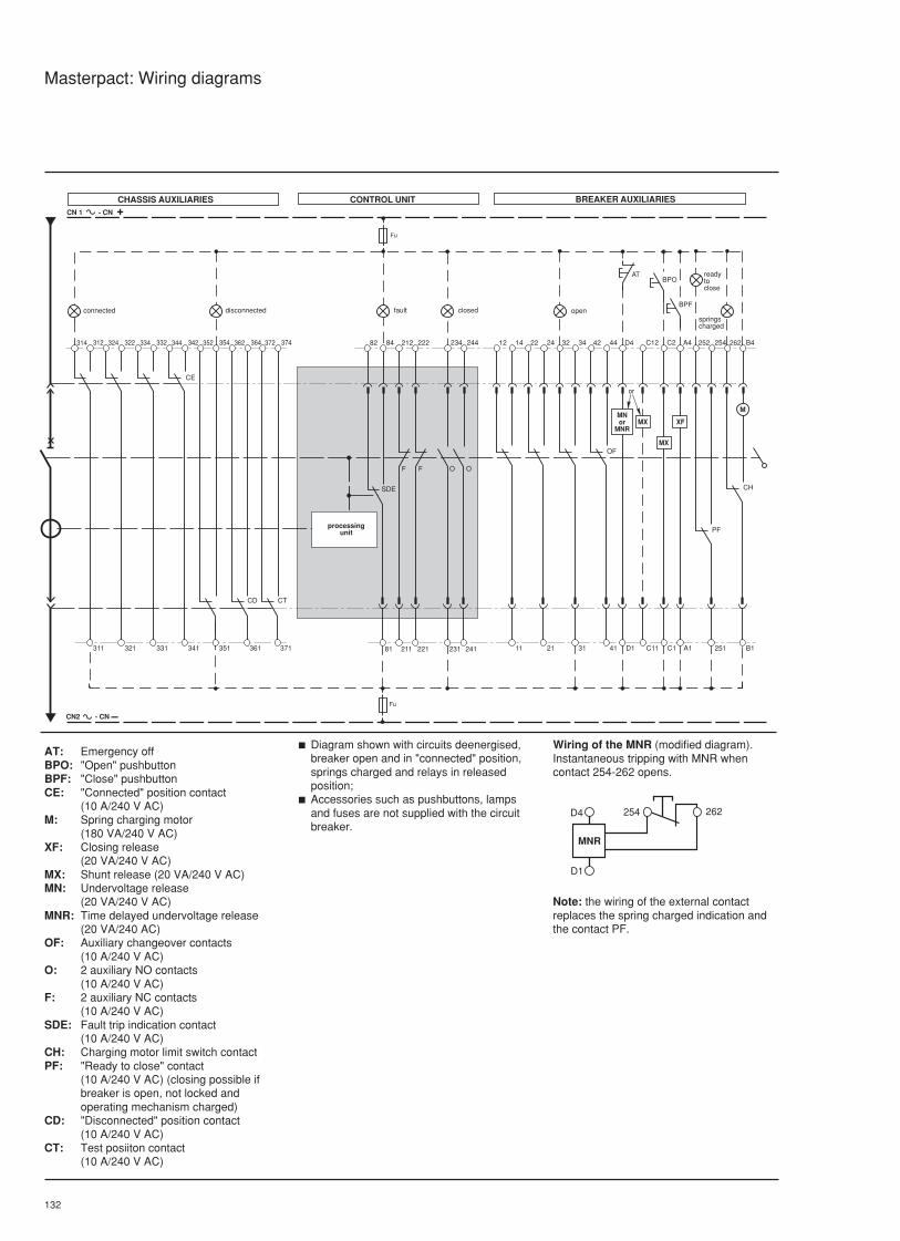
132
Masterpact: Wiring diagrams
12 14
SDE
Fu
81
22 24 32 34
BPO
11 21 31
CN 1 - CN +
CN2 - CN –
Fu
314 312 324 322
311 321
352 354 362 364
CD
351 361
334 332 344 342
CE
331 341
82 84
211
212
221
222
O
231
234
O
241
244 42 44 D4 C12
41 D1
OF
C11
MX
C2
C1
MX
A4
A1
XF
252 254
251
PF
262 B4
B1
CH
AT
BPF
M
F F
372 374
CT
371
disconnected fault openconnected
MNor
MNR
or
readytoclose
springscharged
closed
CHASSIS AUXILIARIES CONTROL UNIT BREAKER AUXILIARIES
processingunit
MNR
D4
D1
254 262
Note: the wiring of the external contactreplaces the spring charged indication andthe contact PF.
AT: Emergency offBPO: "Open" pushbuttonBPF: "Close" pushbuttonCE: "Connected" position contact
(10 A/240 V AC)M: Spring charging motor
(180 VA/240 V AC)XF: Closing release
(20 VA/240 V AC)MX: Shunt release (20 VA/240 V AC)MN: Undervoltage release
(20 VA/240 V AC)MNR: Time delayed undervoltage release
(20 VA/240 AC)OF: Auxiliary changeover contacts
(10 A/240 V AC)O: 2 auxiliary NO contacts
(10 A/240 V AC)F: 2 auxiliary NC contacts
(10 A/240 V AC)SDE: Fault trip indication contact
(10 A/240 V AC)CH: Charging motor limit switch contactPF: "Ready to close" contact
(10 A/240 V AC) (closing possible ifbreaker is open, not locked andoperating mechanism charged)
CD: "Disconnected" position contact(10 A/240 V AC)
CT: Test posiiton contact(10 A/240 V AC)
c Diagram shown with circuits deenergised,breaker open and in "connected" position,springs charged and relays in releasedposition;
c Accessories such as pushbuttons, lampsand fuses are not supplied with the circuitbreaker.
Wiring of the MNR (modified diagram).Instantaneous tripping with MNR whencontact 254-262 opens.

133
T1T2 12 14
SDE
Fu
81
22 24 32 34
BPO
11 21 31
CN 1 - CN +
CN2 - CN –
Fu
314
311
82 84
211
212
221
222
O
231
234
O
241
244 42 44 D4 C12
41 D1
OF
C11
MX
C2
C1
MX
A4
A1
XF
252 254
251
PF
262 B4
B1
CH
AT
BPF
M
F F
311 321 331 341 351 361
312
324
322
334
332
344
342
352
354
362
364
N
S1
S2
CE
CD
371
372
374
CT
C
V2
V1
V
Z21 Z22 F1F2
(3)
R
(2)
P1
P2
(5)Z11
LR1
Z12 LR2 R1 R2
(4)
Ic1 Ic2
e + e –
(4)
ALR
T
F
C
disconnected fault openconnected
MNor
MNR
readytoclose
springscharged
closed
power supply(1)
LRalarm
CHASSIS AUXILIARIES CONTROL UNIT BREAKER AUXILIARIES
proce-ssingunit
ammeter
or
Masterpact: Wiring diagrams
STR 28 D / 38 S / 58 UWith options
MNR
D4
D1
254 262
V contact wiring:for breaker locking, depending on theselected fault.
MX
C2
C1
V
V
V
CN1/CN +
CN2/CN –
BPO
Selective locking needs:
c External power supply (F1, F2);
c An additional terminal (BS).
AT: Emergency offBPO: "Open" pushbuttonBPF: "Close" pushbuttonLR: Long time trip (LT) indicating lampCR: Short time trip (ST) indicating lampT: Earth fault trip indicating lampCE: "Connected" position contact
(10 A/240 V AC)M: Spring charging motor
(180 VA/240 V AC)R: Load monitoring and controlXF: Closing release (20 VA/240 V AC)T: Earth fault protection (EZ and SZ:
input and output for zone selectiveinterlocking)
MX: Shunt release (20 VA/240 V AC)MN: Undervoltage release
(20 VA/240 V AC)MNR: Time delayed undervoltage release
(20 VA/240 V AC)OF: Auxiliary changeover contacts
(10 A/240 V AC)O: 2 auxiliary NC contacts
(10 A/240 V AC)F: 2 auxiliary NC contacts
(10 A/240 V AC)SDE: Fault trip indication contact
(10 A/240 V AC)CH: Charging motor limit switch contactF: Fault trip local indicatorFV: Segregated fault trip indication
contact (5 A/240 V AC)
PF: "Ready to close" contact(10 A/240 V AC) (closing possible ifbreaker is open, not locked andoperating mechanism charged)
CD: "Disconnected" position contact(10 A/240 V AC)
CT: Test position contact (10 A/240 V AC)C: Communication.
c Ic1: load shedding command accordingto Ic1 settingIc2: load shedding command according toIc2 setting;
c Diagram shown with circuits deenergised,breaker open and in "connected" position,springs charged and relays in releasedposition;
c Accessories such as pushbuttons, lampsand fuses are not supplied with the circuit
Note: the wiring of the external contactreplaces the spring charged indication andthe contact PF.
Wiring of the MNR (modified diagram).Instantaneous tripping with MNR whencontact 254-262 opens.
(1) Power supply terminals for I or T or F options(AD module with BAT battery module for backuppower).
(2) Zone selective interlocking with line sidebreaker.
(3) Zone selective interlocking with load sidebreaker (remove jumper).
(4) DC power supply. R contacts reset requestwiring of an external contact.
(5) With Z and/or C options, terminal 84 is notavailable.
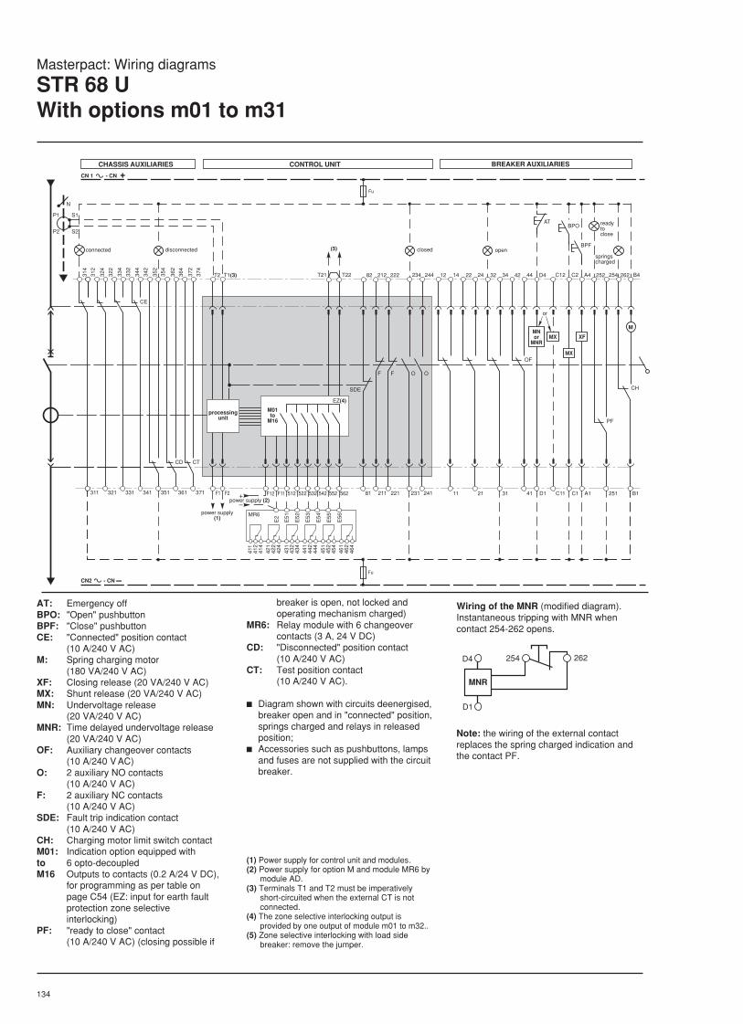
134
Note: the wiring of the external contactreplaces the spring charged indication andthe contact PF.
Wiring of the MNR (modified diagram).Instantaneous tripping with MNR whencontact 254-262 opens.
Masterpact: Wiring diagrams
STR 68 UWith options m01 to m31
12 14
SDE
Fu
81
22 24 32 34
BPO
11 21 31
CN 1 - CN +
CN2 - CN –
Fu
314
311
82
211
212
221
222
O
231
234
O
241
244 42 44 D4 C12
41 D1
OF
C11
MX
C2
C1
MX
A4
A1
XF
252 254
251
PF
262 B4
B1
CH
AT
BPF
M
F F
321 331 341 351 361
312
324
322
334
332
344
342
352
354
362
364
N
S1
S2
CE
CD
T1(3)T2
371
372
374
CT
F1 F2 542 552
T21
562
T22
F11 532
P1
P2
EZ(4)
522512F12+–
E2
E56
E55
E54
E53
E52
E51
411
412
414
421
422
424
431
432
434
441
442
444
451
452
454
461
462
464
MR6
(5)disconnected openconnected
MNor
MNR
readytoclose
springscharged
closed
power supply(1)
power supply (2)
M01to
M16
processingunit
or
CHASSIS AUXILIARIES CONTROL UNIT BREAKER AUXILIARIES
MNR
D4
D1
254 262
AT: Emergency offBPO: "Open" pushbuttonBPF: "Close" pushbuttonCE: "Connected" position contact
(10 A/240 V AC)M: Spring charging motor
(180 VA/240 V AC)XF: Closing release (20 VA/240 V AC)MX: Shunt release (20 VA/240 V AC)MN: Undervoltage release
(20 VA/240 V AC)MNR: Time delayed undervoltage release
(20 VA/240 V AC)OF: Auxiliary changeover contacts
(10 A/240 V AC)O: 2 auxiliary NO contacts
(10 A/240 V AC)F: 2 auxiliary NC contacts
(10 A/240 V AC)SDE: Fault trip indication contact
(10 A/240 V AC)CH: Charging motor limit switch contactM01: Indication option equipped withto 6 opto-decoupledM16 Outputs to contacts (0.2 A/24 V DC),
for programming as per table onpage C54 (EZ: input for earth faultprotection zone selectiveinterlocking)
PF: "ready to close" contact(10 A/240 V AC) (closing possible if
breaker is open, not locked andoperating mechanism charged)
MR6: Relay module with 6 changeovercontacts (3 A, 24 V DC)
CD: "Disconnected" position contact(10 A/240 V AC)
CT: Test position contact(10 A/240 V AC).
c Diagram shown with circuits deenergised,breaker open and in "connected" position,springs charged and relays in releasedposition;
c Accessories such as pushbuttons, lampsand fuses are not supplied with the circuitbreaker.
(1) Power supply for control unit and modules.(2) Power supply for option M and module MR6 by
module AD.(3) Terminals T1 and T2 must be imperatively
short-circuited when the external CT is notconnected.
(4) The zone selective interlocking output isprovided by one output of module m01 to m32..
(5) Zone selective interlocking with load sidebreaker: remove the jumper.

135
Module Terminal number512 522 532 542 552 562
Relay outputs Basic versionm01 LT ST/Inst. ASOther versionsm02 LT ST/Inst. limit 1 limit 2 shed 1 shed 2m03 LT ST/Inst. limit 1 limit 2 shed 1 reconn. 1m04 LT ST/Inst. limit 1 AS shed 1 shed 2m05 limit 2 ST/Inst. limit 1 AS shed 1 shed 2m06 LT ST/Inst. limit 1 AS shed 1 reconn. 2m07 LT ST/Inst. T limit 1 shed 1 shed 2m08 LT ST/Inst. T AS limit 1 Zm09 LT ST/Inst. T AS shed 1 shed 2m10 LT ST/Inst. T Z shed 1 shed 2m11 limit 2 ST/Inst. T limit 1 shed 1 shed 2m12 LT ST/Inst. T Z shed 1 reconn. 2m13 limit 1 ST/Inst. T AS shed 1 shed 2m14 limit 1 ST/Inst. T Z shed 1 shed 2m15 Z ST/Inst. T AS shed 1 reconn. 2m16 LT ST Inst. AS T
512 522 1 6 5 9Transmission m17 ST/Inst. LT reception outputs m18 ST/Inst. AS
m19 T ST/Inst.m20 T AS data transmissionm21 T Zm22 Z ASm23 Z limit 1m24 Z shed 1 e+ e– s+ s–
m25 T shed 1 output output input inputm26 ST/Inst. limit 1m27 ST/Inst. shed 1m28 limit 2 limit 1m29 shed 2 shed 1m30 reconn. 2 shed 1m31 shed 1 AS
Protection:LT Long time trip indication
ST/Inst. Short time or instantaneous tripindication
T Earth fault trip indication
Z Zone selective interlocking output
Load monitoring and control:Limit 1 Indication of Ic1 setting overrun
Limit 2 Indication of Ic2 setting overrun
Shed 1 Load shedding commandaccording to Ic1 setting (limit 1)
Shed 2 Load shedding commandaccording to Ic2 setting
Reconn. 2 Load reconnection commandaccording to Ic2 setting (limit 2)
Self-monitoring:AS Indication of control unit fault or
overtemperature.
Connection modification fordata transmission: options m17 to m31
T1T2
F1 F2
T21 T22
F11 522512F12
(3)
e + e – r + r –
542 562552532
2 431
(3)
S1 (4) S2 (4)
–+
0V
24V(3)
4589
RD–TD–RD+TD+ (5)
1 3 2 1 3 2
power supply(2)
Sub D9connector
ET 44 interface (1)
datatransmissionM17to
M31
processingunit
(1) Communication interface for RS485 - 9600 baudnetwork.
(2) Power supply for m option and ET44 interface(AD module).
(3) Provided connectors.(4) Remote controlled relay output (10 A, 220 V AC).(5) JBUS, RS485, 9600 baud network.
Masterpact: Wiring diagrams
STR 68 UWith options m01 to m31
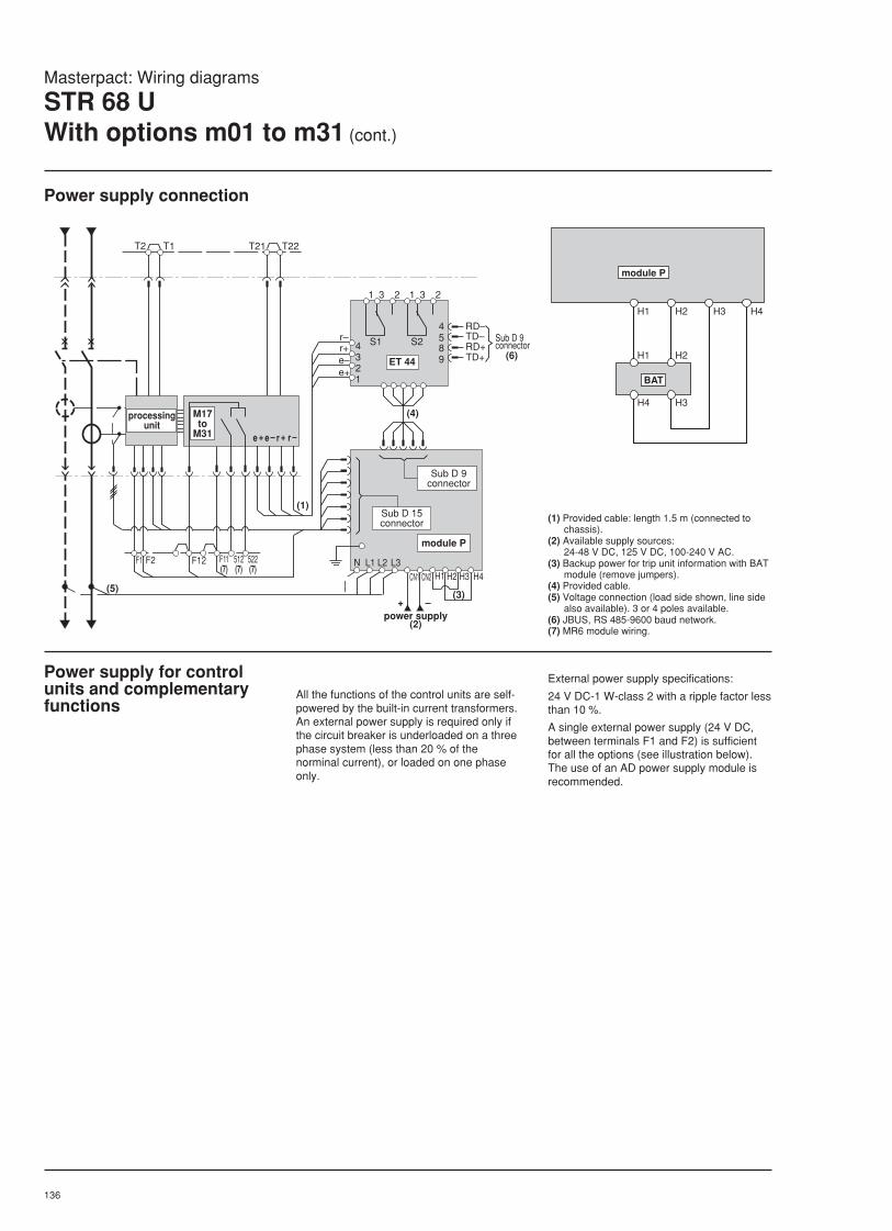
136
T1T2 T21 T22
(5)
512(7)
522(7)
F11(7)
e + e – r + r –
H4H3H2H1CN2
L3L2L1N
CN1
(3)
(4)
r–r+e–e+
4321
(6)
4589
RD–TD–RD+TD+
S1 S2
(1)
1 3 2 1 3 2
–+
F1 F2 F12
ET 44
module P
M17 to
M31
Sub D 15connector
power supply(2)
Sub D 9connector
Sub D 9connector
processingunit
Masterpact: Wiring diagrams
STR 68 UWith options m01 to m31 (cont.)
Power supply connection
Power supply for controlunits and complementaryfunctions
All the functions of the control units are self-powered by the built-in current transformers.An external power supply is required only ifthe circuit breaker is underloaded on a threephase system (less than 20 % of thenorminal current), or loaded on one phaseonly.
External power supply specifications:
24 V DC-1 W-class 2 with a ripple factor lessthan 10 %.
A single external power supply (24 V DC,between terminals F1 and F2) is sufficientfor all the options (see illustration below).The use of an AD power supply module isrecommended.
(1) Provided cable: length 1.5 m (connected tochassis).
(2) Available supply sources:24-48 V DC, 125 V DC, 100-240 V AC.
(3) Backup power for trip unit information with BATmodule (remove jumpers).
(4) Provided cable.(5) Voltage connection (load side shown, line side
also available). 3 or 4 poles available.(6) JBUS, RS 485-9600 baud network.(7) MR6 module wiring.
H1 H2 H3 H4
H1 H2
H4 H3
module P
BAT

137
Control unit STR 68 without power moduleAC supply without indicators maintained after tripping
110 - 220 - 380 V 50/60 Hz
- +
F1 F2 F11 F12
controlunit
M01 to M16option
moduleMR6
moduleAD
110 - 220 - 380 V 50/60 Hz
- +
F1 F2 F11 F12 0V 24V
controlunit
M17 to M31option
moduleET 44
moduleAD
AC supply with indicators maintained after trippingDC supply with or without indicators maintained after tripping
110 - 220 - 380 V 50/60 Hz24/30 - 48/60 - 110/125 V CC
- +
F1 F2 F11 F12
- +
controlunit
M01 to M16option
moduleMR6
moduleBAT
moduleBAT
moduleAD
moduleAD
110 - 220 - 380 V 50/60 Hz24/30 - 48/60 - 110/125 V CC
- +
F1 F2 F11 F12
- +
- +
0V 24V
controlunit
M17 to M31option
moduleET44
moduleBAT
moduleBAT
moduleAD
moduleAD
STR 68 control unit with power moduleAC or DC supply with or without indicators maintained after tripping
100/240 V 50/60 Hz24/28 - 125 V CC
F1 F2 F11 F12
Cn2-Cn1+
controlunit
M17 to M31option
moduleMR6
moduleP
moduleBAT
100/240 V 50/60 Hz24/28 - 125 V CC
F1 F2 F11 F12
Cn2-Cn1+
controlunit
M01 to M16option
moduleMR6
moduleP
moduleBAT
Note: the battery module (BAT) providesback up power to the indicators on the tripunit front face to maintain indications aftertripping. It can be omitted if the auxiliarysupply is reliable.
Masterpact: wiring diagrams
STR 68 UWith options m01 to m31 (cont.)

138
Masterpact: Wiring diagrams
Manual source changeover
Connection Version represented:With lockout after a fault. If lockout after afault is not required, contact PF of the"normal" breaker must be connected directlyin series with contact OF of the"replacement" breaker and vice versa,without passing through the contact SDE.
The indication circuitry, shown in brokenlines below, is optional. The accessoriessuch as voltage relays, indicator lights andfuses are not included with the circuit
possible statesNormal 0 1 0Replacement 0 0 1
CE
314
312
SDE
MX
M
PF
CH
XF
82 84 C2
A4
252
254
262
B4
OF
22 24
311 81 21 C1 A1
251 B1
OF
111412
A
B
F3 (2)
F2 (2)F1 (2)
F4 (2)
C
D
RTs
RTn
CN1
CN2
(3)
(3)
CE
314
312
SDE
MX
M
PF
CH
82 84 C2
A4
252
254
262
B4
OF
22 24
311 81 21 C1 A1
251 B1
OF
111412
XF
"NORMAL" BREAKER AUXILIARIES "REPLACEMENT" BREAKER AUXILIARIES WIRING DIAGRAM PRINCIPLEOF THE AUTOMATISM
closed
open
fault
to A
closed
open
fault
to B
to C
NORMAL
REPLACEMENT
powersupply
D: P25M circuit breaker (2 x 10 A)F1, F2, F3, F4: protection fusesRTs: Voltage relay for "replacement"
sourceRTn: Voltage relay for "normal" sourceCE: "Connected" position contactM: Spring charging motorXF: Closing releaseMX: Shunt releaseOF: Auxiliary changeover contactSDE: Overcurrent trip indication contactCH: "Springs charged" contactPF: "Ready to close" contact
c Diagram shown with circuits de-energised,breaker open and in "connected" position,springs charged and relays in releasedposition.
Note: the fuses allow clearing of all faultsoccurring on the indications circuitry withoutinterruption of the source changeoversystem.

139
Wiring diagram
Source-changeover system with 2 circuit breakers withoutautomatic control Masterpact
QN
314
CE
312
M
PFCH
252
254
262
B4
311 25
1
B1
82 84
SDE
81
OF
12 1411
MX
C2
C1
XF
A4
A1
N R
GN
RD
BK
VT
WH
GN
RD
BK
VT
WH
YE
BN
GY
YE
BN
GY
314
CE
312
M
PFCH
252
254
262
B4
311 25
1
B1
82 84
SDE
81
OF
12 1411
MX
C2
C1
XF
A4
A1(3) (2)
(3)
QR
(3)
(3) (2)
(1)
(1)
"NORMAL" BREAKER AUXILIARIES "REPLACEMENT" BREAKER AUXILIARIES
IVE
N
R
Possible states“Mains” 0 1 0“Standby” 0 0 1
QN: Masterpact on «Mains» source
QR: Masterpact on «Standby» source
IVE: Electrical interlocking and terminalblock unit
M: Motor mechanism
XF: Closing release
MX: Shunt release
CE: Connected position switch
OF: Auxiliary changeover switch
SDE: Overcurrent fault-trip indication switch
CH: «Springs charged» switch
PF: «Ready to close» contact (closingonly possible if device is open,unlocked and operating mechanismcharged).
Diagram shown with circuitsde-energised, breakers open and in«connected» position, springs chargedand relays in released position.
(1) Factory wiring, cannot be modified.

140
ACP
24 N O L 9 10 R E 25
IVEN
R
24 N O L
BA/UA
R E 25
N R
Q1
1
2
3
4
5
6
Q2
1
2
3
4
5
6
Q3
Q5
1718
2021
11 12 13 14 15 16
1 2 3 4 5 6 7 8 9 10
1211 13 14 15 16 10 9 8 7 6 523
22
controller statusindication
voluntary transfercommand (e.j. forenergy management)
URcontact
23 22 27 26 28 30 29 31
loadshedding
genset shutdown
loadshedding
gensetstartup
gensetstartup
load reconnection
+–0V24V
+ – 0V 24V
BatiBUSloop
BatiBUSloop
Connection diagrams
Source-changeover system with controller for Compactand Masterpact circuit breakers
Controller UALoad shedding and gensetmanagement
Q1 : Circuit breaker supplying andprotecting the automatic controlcircuits for the “Mains” source
Q2 : Circuit breaker supplying andprotecting the automatic controlcircuits for the “Standby” source
Q3 : Protection circuit breaker
Q5 : Protection circuit breaker
ACP : Auxiliaries control plate
BA/UA : Controller
IVE : Electrical interlocking and terminalblock unit
Diagram shown with circuits de-energised, all devices open andrelays in the
released position.
Tests on “Mains” and “Standby”voltagesBA: Single-phase check for UN and UR:
Tested across terminals 1 and 5 of circuitbreakers Q1 and Q2.
UA: Three-phase check for UN:
Tested across terminals 1, 3 and 5 ofcircuit breaker Q1,
Selection switch A of controller set to 1;
Single-phase check for UN :
Tested across terminals 1 and 5 of circuitbreaker Q1,
Selection switch A of controller set to 0.
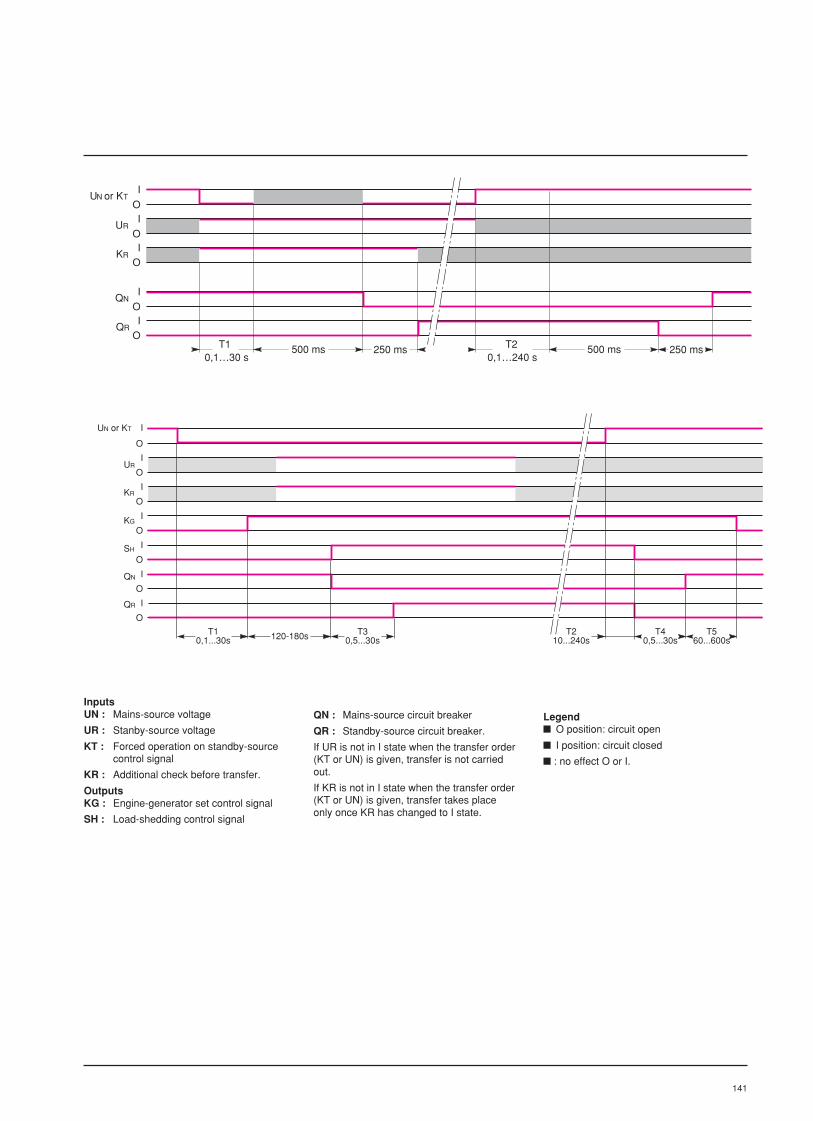
141
I
OI
OI
O
0,1…30 sT1 500 ms 250 ms
I
OI
O
UN T
UR
KR
QN
QR
250 ms 500 ms 0,1…240 s
T2
or K
T10,1...30s
I
O
I
O
I
O
I
O
I
O
I
O
I
O
UR
KR
KG
SH
QN
QR
120-180s T30,5...30s
T210...240s
T40,5...30s
T560...600s
UN or KT
InputsUN : Mains-source voltage
UR : Stanby-source voltage
KT : Forced operation on standby-sourcecontrol signal
KR : Additional check before transfer.
OutputsKG : Engine-generator set control signal
SH : Load-shedding control signal
QN : Mains-source circuit breaker
QR : Standby-source circuit breaker.
If UR is not in I state when the transfer order(KT or UN) is given, transfer is not carriedout.
If KR is not in I state when the transfer order(KT or UN) is given, transfer takes placeonly once KR has changed to I state.
Legend O position: circuit open
I position: circuit closed
: no effect O or I.

142
251
arméBPF
AT
ouvert
DINA/STR 08 AUXILIAIRES APPAREIL
CN 1 - CN +
Fu
défaut fermé
BPO
prêt àfermer
262 B4254252A4C2C12D444423432242214122442342222128482
F F O O
81 211 221 231 241
SDE(1)
11 21 31 41 D1
OF
MNou
MNRMX
MX
XF Mou
C11 C1 A1
PF
CH
B1
Fu
CN2 - CN –
Masterpact: Wiring diagrams DC range
MNR wiring for instantaneous trippingSymbolsFu: 2 A protection fuseAT: Emergency offBPO: Opening pushbuttonBPF: Closing pushbuttonM: Charging motor (180 W)XF: Closing release (15 W)MX: Shunt release (15 W)MN: Undervoltage release (15 W)MNR: Time-delayed undervoltage release(15 W) (2)OF: Changeover auxiliary switchesO: Normally open auxiliary switchesF: Normally closed auxiliary switchesSDE: Fault-trip indication contactCH: "Spring charged" contactPF: "Ready to close" contact
Accessories such as pushbuttons, fuses,etc. are not supplied with the circuit breaker.The diagram is shown without the supplyvoltage present, all devices open, connectedand charged, relays in the de-energisedposition and the MN or MNR supplied withpower.
(1) Only for the DINA trip unit.(2) The MNR requires AC current.
CB AUXILIARY CIRCUITS
fault closed open charged
readyto close
or
or
Utilise les bornes 262 (signalisation "ressorts chargés") et 254 (contact à fermeture du PF)
MNR
D4
D1
254 262
Use terminals 262(«spring charged» indication)and 254 (PF make switch).

143
LV air circuit breakersand switch-disconnectors
Masterpact80 to 6300 Amp
Order form
Section 10
10

144
Unprotected A.C.B
STR 18M instantaneous protection
STR 28D distribution protection
ammeter
overrun alarm contact
STR 38S selective protection
ammeter
overrun alarm contact
earth "residual"faultprotection "source ground
return"fault indicator
power supply with battery
STR 58U universal protection
ammeter
overrun alarm contact
earth "residual"faultprotection "source ground
return"fault indicator
power supply with battery
zone selective interlocking
charge monitoring
segregated alarm switch(fault indicator F included)communication
long time protection inhibition
STR 68U universal protection
power supply voltage
service continuity
module type
power measurement
earth "residual"faultprotection "source ground
return"control relay moduleunitaccessories interface module
power supply module
safeguard battery module
sealable cover
automatic reset
Quantity
Rating (08... 63)
Type N, H, L, ES (earthing switch)
or 1000 V AC type
Number of poles
Sensor rating
Version fixed
complete drawout
drawout - moving portion only
fixed portion only
Connection top horizontal
vertical
front
bottom horizontal
vertical
front
Neutral protection
full
reduced
Neutral on right-hand
Environment special conditions
Masterpact : Price list
MasterpactDetailed order form (AC range)
For faster order processing, please use the following order form.For each section, tick the box or indicate the value corresponding to your choice.
STR 18M
STR 28D
I
ALR
STR 38S
I
ALR
T
W
F
PIL
STR 58U
I
ALR
T
W
F
PIL
Z
R
FV
C
PLROFF
STR 68U
YES
M
P
T
W
MR6
ET44
AD
BAT
PBD
RAR
IN
TCE
F
D
A
C
P
C
A
P
C
A
NONE
N
N/2
1 - Circuit breaker 2 - Control unit
Note : this order form does not take into account possible incompatibilities
standard
standard
V
NO
V

145
Pushbutton locking device
"Off" position lock
Disconnected position locking
Connected - test - disconnectedposition locking
Installation righthand door lockaccessories
lefthand door lock
racking interlock in openposition doorwithdrawal/springcharged interlocksafety shutters
shutter lock (1 or 2)
arc chute cover
terminal shield
inter phase barriers
partitioning fixture
door frame
door frame withtransparent coverbreaker mismatch protection
Manual operating mechanism (only)
Electrical geared motoroperatingmechanism operations counter
closing releasevoltage releasespecify below
Voltage shunt releaserelease
undervoltage release
time delayed undervoltage
with instant wiring
Auxiliary 2O+2C+SDEswitch
4 changeovers
24 additional changeover
ready to close
4 connected position switches
2 disconnected position switches
1 test position switch
Auxiliary connection accessoriesadditionnal terminal block
Separate components fixed/mixed complete drawoutMechanicalinterlocking
Automatic changeovercontrollerDiagram number
Complete assemblies fixed/mixed complete drawout2 alone breakers
2 breakers withcontrollerDiagram number
Controller voltage
Breaker position
Standby
3 alone breakers
Diagram number
Mechanicalinterlocking
Breaker position : specify their characteristicstop/medium/bottom with order
VM2CT
VM2CC
VM33CT
VM32CT
VM31CT
AIS380C
top
VM33CT
VM32CT
VM31CT
VM2FT
VM2FC
VM33FT
VM32FT
VM31FT
AIS240C60H
bottom
VM33FT
VM32FT
VM31FT
VSPA1
VSPRAC
VSRA2
VSKA
VSPC1
VSRC2
VSRC1
2VSRC1
VSKC
VSEPC
VSERC
VSECC
VEC
MCH
CDM
XF
MX
MN
MNR
MNRI
OF
OFSUP
PF
CE
CD
CT
BS
V
V
V
V
V
V
standard
VBP
VSPA2
VSRA1
VSCA
VSPC2
VSPRCC
VSCC
2VSPC1
2VSEPC
2VSERC
VSEKC
VPECD
VPECG
VPOC
VEAA
VO
VVC
CC
CB
EIP
AC
CDP
CCP
VDC
3 - Electrical auxiliaries
5 - Manual and automatic source changeover
Note : this order form does not take into account possible incompatibilities
4 - Mechanical and installation accessories
Masterpact : Price list
MasterpactDetailed order form (AC range)

146
Quantity
Rating 1000 A
2000 A
4000 A
6000 A
8000 A
Maximum 500 V up to 4000 Avoltage
750 V up to 4000 A
1000 V up to 4000 A
250 V 6000-8000 A
Type (for distribution system selection, see diagrams opposite)
up to 4000 Aall systems 3 poles(n° 1-2-3/1st alt.) 500 V max.isolated network 4 poles(n° 1) 1000 V max.earthed 4 polesmiddle point 1000 V max.(n° 2)earthed negative 3 polespolarity 750 V max.(n° 3/2nd alt.)earthed negative 4 polespolarity 750 V max.(n° 3/1st alt.)earthed negative 4 polespolarity 1000 V max.(n° 3/2nd alt.)
6000 A - 8000 Aall systems 2 poles(n° 1-2-3) 250 V max.
Version fixed up to 4000 A
drawout
drawout without chassis
chassis only
Connection top horizontal(up to 2000 A)vertical
bottom horizontal(up to 2000 A)vertical
Environment for grease protection
M10DC
M20DC
M40DC
M60DC
M80DC
500 V
750 V
1000 V
250 V
D
E
E
H
F
J
G
F
D
A
C
P
C
P
C
PROTGF
Masterpact : Price list
MasterpactOrder form (DC range)
For faster order processing, please use the following order from.For each section, tick the box for indicate the value corresponding to your choice.
1 - Circuit breaker
network n° 1 isolated network
load
network n° 2 earthed middle point
load
network n° 3 earthed negative polarity(1st alternative)
load
network n° 3 earthed negative polarity(2nd alternative)
load
Diagrams
Note : this order form does not take into account possible incompatibilities

147
Pushbutton locking device
"Off" position locking device
"Disconnected" position locking device
"Disconnected/connected/test"position locking device
Installation right-hand door interlockaccessories
left-hand door interlock
racking interlock
withdrawal/springcharged interlocksafety shutters (standard)
shutter lock (1 or 2)
arc-chute cover(standard)door frame
transparent cover
circuit breakermismatch protection
Type without switch
or instantaneous 1500 A - 3000 ADINA forM10-M20-M40 3000 A - 6000 A
6 kA - 12 kA
10 kA - 20 kA
or instantaneous 9 kA - 18 kADINA forM60-M80 12 kA - 24 kA
20 kA - 40 kA
Assessories sealable cover
Manual operating mechanism only
Electrical gear-motoroperatingmechanism operations counter
closing release
Voltage shunt releasereleases
instantaneous undervoltage
time delayed undervoltage
with instant wiring
Auxiliary 4 changeover contactsswitches
automatic reset
ready to close
Accessory disconnectable plugfor (1 or 2)auxiliary compulsoryconnections
VBP
VSPA1
VSPA2
VSPRAC
VSRA1
VSRA2
VSPC1
VSPC2
2VSPC1
VSPRCC
VSRC1
VSRC2
2VSRC1
VSEPC
2VSEPC
VSERC
2VSERC
VEC
VPECD
VPECG
VPOC
VEAA
VO
VCC
CC
CDP
CCP
VDC
STR 08I
1.5/3 K
03/06 K
06/12 K
10/20 K
9/18 K
12/24 K
20/40 K
PBC
MCH
CDM
XF
MX
MN
MNR
MNRI
OF
RAR
PF
DP
2 - Protection
3 - Electrical auxiliaries
V
V
V
V
V
V
standard
4 - Mechanical and installation accessories
standard
standard
Note : this order form does not take into account possible incompatibilities
Masterpact : Price list
MasterpactOrder form (DC range)


