264
DOCA0054EN-01 www.schneider-electric.com Masterpact NT/NW, Compact NS DOCA0054EN-01 10/2014 Masterpact NT/NW, Compact NS Modbus Communication Guide 10/2014

Masterpact NT/NW, Compact NS
DOCA0054EN-01 10/2014
DO
CA
005
4EN
-01
www.schneider-electric.com
Masterpact NT/NW, Compact NSModbus Communication Guide
10/2014

The information provided in this documentation contains general descriptions and/or technical characteristics of the performance of the products contained herein. This documentation is not intended as a substitute for and is not to be used for determining suitability or reliability of these products for specific user applications. It is the duty of any such user or integrator to perform the appropriate and complete risk analysis, evaluation and testing of the products with respect to the relevant specific application or use thereof. Neither Schneider Electric nor any of its affiliates or subsidiaries shall be responsible or liable for misuse of the information contained herein. If you have any suggestions for improvements or amendments or have found errors in this publication, please notify us.
No part of this document may be reproduced in any form or by any means, electronic or mechanical, including photocopying, without express written permission of Schneider Electric.
All pertinent state, regional, and local safety regulations must be observed when installing and using this product. For reasons of safety and to help ensure compliance with documented system data, only the manufacturer should perform repairs to components.
When devices are used for applications with technical safety requirements, the relevant instructions must be followed.
Failure to use Schneider Electric software or approved software with our hardware products may result in injury, harm, or improper operating results.
Failure to observe this information can result in injury or equipment damage.
© 2014 Schneider Electric. All rights reserved.
2 DOCA0054EN-01 10/2014

Table of Contents
Safety Information . . . . . . . . . . . . . . . . . . . . . . . . . . . . . . . . . . . . . . . . . . . 7About the Book. . . . . . . . . . . . . . . . . . . . . . . . . . . . . . . . . . . . . . . . . . . . . . 9
Chapter 1 Modbus Communication with Masterpact NT/NW and Compact NS. . . 111.1 Introduction . . . . . . . . . . . . . . . . . . . . . . . . . . . . . . . . . . . . . . . . . . . . . . . . . . . . . . . . . . . . . . 12
Introduction . . . . . . . . . . . . . . . . . . . . . . . . . . . . . . . . . . . . . . . . . . . . . . . . . . . . . . . . . . . . . . 13Customer Engineering Tool . . . . . . . . . . . . . . . . . . . . . . . . . . . . . . . . . . . . . . . . . . . . . . . . . 15
1.2 IFM Modbus-SL Interface for LV Circuit Breaker. . . . . . . . . . . . . . . . . . . . . . . . . . . . . . . . . . 17Description. . . . . . . . . . . . . . . . . . . . . . . . . . . . . . . . . . . . . . . . . . . . . . . . . . . . . . . . . . . . . . . 18Schematics With Masterpact NT/NW and Compact NS Circuit Breakers . . . . . . . . . . . . . . . 21Configuration . . . . . . . . . . . . . . . . . . . . . . . . . . . . . . . . . . . . . . . . . . . . . . . . . . . . . . . . . . . . . 26Communication Test . . . . . . . . . . . . . . . . . . . . . . . . . . . . . . . . . . . . . . . . . . . . . . . . . . . . . . . 27
1.3 IFE Ethernet Interface for LV Circuit Breaker . . . . . . . . . . . . . . . . . . . . . . . . . . . . . . . . . . . . 28Introduction . . . . . . . . . . . . . . . . . . . . . . . . . . . . . . . . . . . . . . . . . . . . . . . . . . . . . . . . . . . . . . 29Hardware Description . . . . . . . . . . . . . . . . . . . . . . . . . . . . . . . . . . . . . . . . . . . . . . . . . . . . . . 32Schematics With Masterpact NT/NW and Compact NS Circuit Breakers . . . . . . . . . . . . . . . 35
Chapter 2 Modbus Protocol with Masterpact NT/NW and Compact NS . . . . . . . . . 41Modbus Master-Slave Principle. . . . . . . . . . . . . . . . . . . . . . . . . . . . . . . . . . . . . . . . . . . . . . . 42Modbus Functions . . . . . . . . . . . . . . . . . . . . . . . . . . . . . . . . . . . . . . . . . . . . . . . . . . . . . . . . . 45Modbus Exception Codes . . . . . . . . . . . . . . . . . . . . . . . . . . . . . . . . . . . . . . . . . . . . . . . . . . . 49Write Protection . . . . . . . . . . . . . . . . . . . . . . . . . . . . . . . . . . . . . . . . . . . . . . . . . . . . . . . . . . . 50Password Management. . . . . . . . . . . . . . . . . . . . . . . . . . . . . . . . . . . . . . . . . . . . . . . . . . . . . 51Command Interface . . . . . . . . . . . . . . . . . . . . . . . . . . . . . . . . . . . . . . . . . . . . . . . . . . . . . . . . 52Command Examples . . . . . . . . . . . . . . . . . . . . . . . . . . . . . . . . . . . . . . . . . . . . . . . . . . . . . . . 56Date Management . . . . . . . . . . . . . . . . . . . . . . . . . . . . . . . . . . . . . . . . . . . . . . . . . . . . . . . . . 58Modbus Registers Tables . . . . . . . . . . . . . . . . . . . . . . . . . . . . . . . . . . . . . . . . . . . . . . . . . . . 59
Chapter 3 Data-Set . . . . . . . . . . . . . . . . . . . . . . . . . . . . . . . . . . . . . . . . . . . . . . . . . . . . 653.1 Standard Data-Set. . . . . . . . . . . . . . . . . . . . . . . . . . . . . . . . . . . . . . . . . . . . . . . . . . . . . . . . . 66
Standard Data-Set . . . . . . . . . . . . . . . . . . . . . . . . . . . . . . . . . . . . . . . . . . . . . . . . . . . . . . . . 67Modbus Registers . . . . . . . . . . . . . . . . . . . . . . . . . . . . . . . . . . . . . . . . . . . . . . . . . . . . . . . . . 68Standard Data-Set Common Registers . . . . . . . . . . . . . . . . . . . . . . . . . . . . . . . . . . . . . . . . . 70Readout Examples . . . . . . . . . . . . . . . . . . . . . . . . . . . . . . . . . . . . . . . . . . . . . . . . . . . . . . . . 81
3.2 Legacy Data-Set . . . . . . . . . . . . . . . . . . . . . . . . . . . . . . . . . . . . . . . . . . . . . . . . . . . . . . . . . . 83Legacy Data-Set . . . . . . . . . . . . . . . . . . . . . . . . . . . . . . . . . . . . . . . . . . . . . . . . . . . . . . . . . . 84Modbus Registers . . . . . . . . . . . . . . . . . . . . . . . . . . . . . . . . . . . . . . . . . . . . . . . . . . . . . . . . . 85Legacy Data-Set Common Registers . . . . . . . . . . . . . . . . . . . . . . . . . . . . . . . . . . . . . . . . . . 87Readout Examples . . . . . . . . . . . . . . . . . . . . . . . . . . . . . . . . . . . . . . . . . . . . . . . . . . . . . . . . 96
Chapter 4 Micrologic Trip Unit Data for Masterpact NT/NW and Compact NS. . . . 974.1 Micrologic Trip Unit Registers . . . . . . . . . . . . . . . . . . . . . . . . . . . . . . . . . . . . . . . . . . . . . . . . 98
Real-Time Measurements . . . . . . . . . . . . . . . . . . . . . . . . . . . . . . . . . . . . . . . . . . . . . . . . . . . 99Minimum/Maximum Values of Real-Time Measurements . . . . . . . . . . . . . . . . . . . . . . . . . . . 106Energy Measurements . . . . . . . . . . . . . . . . . . . . . . . . . . . . . . . . . . . . . . . . . . . . . . . . . . . . . 107Demand Measurements . . . . . . . . . . . . . . . . . . . . . . . . . . . . . . . . . . . . . . . . . . . . . . . . . . . . 108Spectral Components . . . . . . . . . . . . . . . . . . . . . . . . . . . . . . . . . . . . . . . . . . . . . . . . . . . . . . 110Micrologic Trip Unit Identification. . . . . . . . . . . . . . . . . . . . . . . . . . . . . . . . . . . . . . . . . . . . . . 115Status . . . . . . . . . . . . . . . . . . . . . . . . . . . . . . . . . . . . . . . . . . . . . . . . . . . . . . . . . . . . . . . . . . 118Alarm History . . . . . . . . . . . . . . . . . . . . . . . . . . . . . . . . . . . . . . . . . . . . . . . . . . . . . . . . . . . . . 121Trip History . . . . . . . . . . . . . . . . . . . . . . . . . . . . . . . . . . . . . . . . . . . . . . . . . . . . . . . . . . . . . . 123Analog Predefined Alarms. . . . . . . . . . . . . . . . . . . . . . . . . . . . . . . . . . . . . . . . . . . . . . . . . . . 125Basic Protection Parameters . . . . . . . . . . . . . . . . . . . . . . . . . . . . . . . . . . . . . . . . . . . . . . . . . 129Advanced Protection Parameters . . . . . . . . . . . . . . . . . . . . . . . . . . . . . . . . . . . . . . . . . . . . . 133Configuration of the M2C/M6C Programmable Contacts . . . . . . . . . . . . . . . . . . . . . . . . . . . 149
DOCA0054EN-01 10/2014 3

Measurement Parameters . . . . . . . . . . . . . . . . . . . . . . . . . . . . . . . . . . . . . . . . . . . . . . . . . . . 151Time-Stamped Information. . . . . . . . . . . . . . . . . . . . . . . . . . . . . . . . . . . . . . . . . . . . . . . . . . . 154Maintenance Indicators . . . . . . . . . . . . . . . . . . . . . . . . . . . . . . . . . . . . . . . . . . . . . . . . . . . . . 156Miscellaneous . . . . . . . . . . . . . . . . . . . . . . . . . . . . . . . . . . . . . . . . . . . . . . . . . . . . . . . . . . . . 157
4.2 Micrologic Trip Unit Files . . . . . . . . . . . . . . . . . . . . . . . . . . . . . . . . . . . . . . . . . . . . . . . . . . . . 160File Mechanism . . . . . . . . . . . . . . . . . . . . . . . . . . . . . . . . . . . . . . . . . . . . . . . . . . . . . . . . . . . 161Protection Event Log . . . . . . . . . . . . . . . . . . . . . . . . . . . . . . . . . . . . . . . . . . . . . . . . . . . . . . . 163Metering Event Log . . . . . . . . . . . . . . . . . . . . . . . . . . . . . . . . . . . . . . . . . . . . . . . . . . . . . . . . 165Maintenance Protection Event Log . . . . . . . . . . . . . . . . . . . . . . . . . . . . . . . . . . . . . . . . . . . . 167Maintenance Metering Event Log . . . . . . . . . . . . . . . . . . . . . . . . . . . . . . . . . . . . . . . . . . . . . 169Minimum/Maximum Event Log. . . . . . . . . . . . . . . . . . . . . . . . . . . . . . . . . . . . . . . . . . . . . . . . 171Waveform Capture . . . . . . . . . . . . . . . . . . . . . . . . . . . . . . . . . . . . . . . . . . . . . . . . . . . . . . . . . 173Fault Waveform Capture . . . . . . . . . . . . . . . . . . . . . . . . . . . . . . . . . . . . . . . . . . . . . . . . . . . . 176
4.3 Micrologic Trip Unit Commands . . . . . . . . . . . . . . . . . . . . . . . . . . . . . . . . . . . . . . . . . . . . . . . 179List of Micrologic Trip Unit Commands and Error Codes . . . . . . . . . . . . . . . . . . . . . . . . . . . . 180Measurement Configuration Commands . . . . . . . . . . . . . . . . . . . . . . . . . . . . . . . . . . . . . . . . 181
Chapter 5 BCM ULP Data for Masterpact NT/NW and Compact NS . . . . . . . . . . . . 1855.1 BCM ULP Registers . . . . . . . . . . . . . . . . . . . . . . . . . . . . . . . . . . . . . . . . . . . . . . . . . . . . . . . . 186
BCM ULP Identification . . . . . . . . . . . . . . . . . . . . . . . . . . . . . . . . . . . . . . . . . . . . . . . . . . . . . 187Circuit Breaker Status . . . . . . . . . . . . . . . . . . . . . . . . . . . . . . . . . . . . . . . . . . . . . . . . . . . . . . 188Time-Stamped Information. . . . . . . . . . . . . . . . . . . . . . . . . . . . . . . . . . . . . . . . . . . . . . . . . . . 191Counters. . . . . . . . . . . . . . . . . . . . . . . . . . . . . . . . . . . . . . . . . . . . . . . . . . . . . . . . . . . . . . . . . 192Trip History. . . . . . . . . . . . . . . . . . . . . . . . . . . . . . . . . . . . . . . . . . . . . . . . . . . . . . . . . . . . . . . 193
5.2 BCM ULP Files. . . . . . . . . . . . . . . . . . . . . . . . . . . . . . . . . . . . . . . . . . . . . . . . . . . . . . . . . . . . 195Circuit Breaker Manager Event Log . . . . . . . . . . . . . . . . . . . . . . . . . . . . . . . . . . . . . . . . . . . . 195
5.3 BCM ULP Commands . . . . . . . . . . . . . . . . . . . . . . . . . . . . . . . . . . . . . . . . . . . . . . . . . . . . . . 197List of BCM ULP Commands and Error Codes . . . . . . . . . . . . . . . . . . . . . . . . . . . . . . . . . . . 198Circuit Breaker Control Commands . . . . . . . . . . . . . . . . . . . . . . . . . . . . . . . . . . . . . . . . . . . . 199
Chapter 6 IO Data for Masterpact NT/NW and Compact NS . . . . . . . . . . . . . . . . . . 2016.1 IO Registers . . . . . . . . . . . . . . . . . . . . . . . . . . . . . . . . . . . . . . . . . . . . . . . . . . . . . . . . . . . . . . 202
Analog Inputs . . . . . . . . . . . . . . . . . . . . . . . . . . . . . . . . . . . . . . . . . . . . . . . . . . . . . . . . . . . . . 203Digital Inputs . . . . . . . . . . . . . . . . . . . . . . . . . . . . . . . . . . . . . . . . . . . . . . . . . . . . . . . . . . . . . 205Digital Outputs . . . . . . . . . . . . . . . . . . . . . . . . . . . . . . . . . . . . . . . . . . . . . . . . . . . . . . . . . . . . 207Hardware Setting . . . . . . . . . . . . . . . . . . . . . . . . . . . . . . . . . . . . . . . . . . . . . . . . . . . . . . . . . . 209Digital Input and Output Status . . . . . . . . . . . . . . . . . . . . . . . . . . . . . . . . . . . . . . . . . . . . . . . 210IO Identification . . . . . . . . . . . . . . . . . . . . . . . . . . . . . . . . . . . . . . . . . . . . . . . . . . . . . . . . . . . 211Alarm Status. . . . . . . . . . . . . . . . . . . . . . . . . . . . . . . . . . . . . . . . . . . . . . . . . . . . . . . . . . . . . . 213Applications . . . . . . . . . . . . . . . . . . . . . . . . . . . . . . . . . . . . . . . . . . . . . . . . . . . . . . . . . . . . . . 216
6.2 IO Events . . . . . . . . . . . . . . . . . . . . . . . . . . . . . . . . . . . . . . . . . . . . . . . . . . . . . . . . . . . . . . . . 218Event History . . . . . . . . . . . . . . . . . . . . . . . . . . . . . . . . . . . . . . . . . . . . . . . . . . . . . . . . . . . . . 219IO Events and Alarms . . . . . . . . . . . . . . . . . . . . . . . . . . . . . . . . . . . . . . . . . . . . . . . . . . . . . . 220
6.3 IO Commands . . . . . . . . . . . . . . . . . . . . . . . . . . . . . . . . . . . . . . . . . . . . . . . . . . . . . . . . . . . . 225List of IO Commands and Error Codes . . . . . . . . . . . . . . . . . . . . . . . . . . . . . . . . . . . . . . . . . 226Generic Commands . . . . . . . . . . . . . . . . . . . . . . . . . . . . . . . . . . . . . . . . . . . . . . . . . . . . . . . . 227Application Commands . . . . . . . . . . . . . . . . . . . . . . . . . . . . . . . . . . . . . . . . . . . . . . . . . . . . . 230
Chapter 7 IFM Data for Masterpact NT/NW and Compact NS . . . . . . . . . . . . . . . . . 2337.1 IFM Registers. . . . . . . . . . . . . . . . . . . . . . . . . . . . . . . . . . . . . . . . . . . . . . . . . . . . . . . . . . . . . 234
IFM Identification . . . . . . . . . . . . . . . . . . . . . . . . . . . . . . . . . . . . . . . . . . . . . . . . . . . . . . . . . . 235Modbus Network Parameters. . . . . . . . . . . . . . . . . . . . . . . . . . . . . . . . . . . . . . . . . . . . . . . . . 237
7.2 IFM Commands . . . . . . . . . . . . . . . . . . . . . . . . . . . . . . . . . . . . . . . . . . . . . . . . . . . . . . . . . . . 238List of IFM Commands and Error Codes . . . . . . . . . . . . . . . . . . . . . . . . . . . . . . . . . . . . . . . . 239IFM Commands . . . . . . . . . . . . . . . . . . . . . . . . . . . . . . . . . . . . . . . . . . . . . . . . . . . . . . . . . . . 240
4 DOCA0054EN-01 10/2014

Chapter 8 IFE Data for Masterpact NT/NW and Compact NS. . . . . . . . . . . . . . . . . . 2438.1 IFE Registers. . . . . . . . . . . . . . . . . . . . . . . . . . . . . . . . . . . . . . . . . . . . . . . . . . . . . . . . . . . . . 244
IFE Identification and Status Registers . . . . . . . . . . . . . . . . . . . . . . . . . . . . . . . . . . . . . . . . . 245IP Network Parameters . . . . . . . . . . . . . . . . . . . . . . . . . . . . . . . . . . . . . . . . . . . . . . . . . . . . . 248
8.2 IFE Commands . . . . . . . . . . . . . . . . . . . . . . . . . . . . . . . . . . . . . . . . . . . . . . . . . . . . . . . . . . . 249List of IFE Commands and Error Codes . . . . . . . . . . . . . . . . . . . . . . . . . . . . . . . . . . . . . . . . 250IFE Generic Commands . . . . . . . . . . . . . . . . . . . . . . . . . . . . . . . . . . . . . . . . . . . . . . . . . . . . 251
Appendices . . . . . . . . . . . . . . . . . . . . . . . . . . . . . . . . . . . . . . . . . . . . . . . . . . . . . . 253Appendix A Cross References to Modbus Registers for Masterpact NT/NW and
Compact NS . . . . . . . . . . . . . . . . . . . . . . . . . . . . . . . . . . . . . . . . . . . . . . . . 255Cross References to Modbus Registers . . . . . . . . . . . . . . . . . . . . . . . . . . . . . . . . . . . . . . . . 255
DOCA0054EN-01 10/2014 5

6 DOCA0054EN-01 10/2014

Safety Information
Important Information
NOTICE
Read these instructions carefully, and look at the equipment to become familiar with the device before trying to install, operate, or maintain it. The following special messages may appear throughout this documentation or on the equipment to warn of potential hazards or to call attention to information that clarifies or simplifies a procedure.
PLEASE NOTE
Electrical equipment should be installed, operated, serviced, and maintained only by qualified personnel. No responsibility is assumed by Schneider Electric for any consequences arising out of the use of this material.
A qualified person is one who has skills and knowledge related to the construction and operation of electrical equipment and its installation, and has received safety training to recognize and avoid the hazards involved.
DOCA0054EN-01 10/2014 7

8 DOCA0054EN-01 10/2014

About the Book
At a Glance
Document Scope
The aim of this document is to provide users, installers, and maintenance personnel with the technical information needed to operate the Modbus protocol on the 4 ranges of circuit breakers and switch-disconnectors: Compact NS 630b-1600, 630-1600 A Compact NS 1600b-3200, 1600-3200 A Masterpact NT, 630-1600 A Masterpact NW, 800-6300 A
Validity Note
This document is valid for Masterpact NT/NW and Compact NS circuit breakers with a BCM ULP breaker communication module embedded, and connected: either to an RS 485 serial line Modbus network using an IFM Modbus-SL interface for LV circuit breaker or to an Ethernet network using an IFE Ethernet interface for LV circuit breaker
Refer to the Masterpact Modbus Legacy User Guide for communication architectures using: the Modbus legacy port of the BCM ULP the IFM Modbus-SL interface for LV circuit breaker with the Modbus legacy firmware
Related Documents
You can download these technical publications and other technical information from our website at www.schneider-electric.com.
Title of Documentation Reference Number
Masterpact NT Circuit Breakers and Switch-Disconnectors - User Guide
51201115AA (FR)51201116AA (EN)
Masterpact NW Circuit Breakers and Switch-Disconnectors - User Guide
04443719AA (FR)04443720AA (EN)
Compact NS630b to 1600 A - User Guide 51201639AA (FR)51201640AA (EN)
Micrologic A and E Trip Units - User Guide 04443723AA (FR)04443724AA (EN)
Micrologic P Trip Units - User Guide 04443725AA (FR)04443726AA (EN)
Micrologic H Trip Units - User Guide 04443727AA (FR)04443728AA (EN)
Masterpact NT/NW, Compact NS, PowerPact P- and R-Frame Communication Option - Installation Manual
EAV36080 (EN, FR, ES)
ULP (Universal Logic Plug) System - User Guide TRV99100 (FR)TRV99101 (EN)TRV99102 (ES)
Masterpact Modbus Legacy - User Guide COMBT32EN
DOCA0054EN-01 10/2014 9

10 DOCA0054EN-01 10/2014
Masterpact NT/NW, Compact NS
Modbus Communication with Masterpact NT/NW and Compact NS
DOCA0054EN-01 10/2014
Modbus Communication with Masterpact NT/NW and Compact NS
Chapter 1Modbus Communication with Masterpact NT/NW and Compact NS
What Is in This Chapter?
This chapter contains the following sections:
Section Topic Page
1.1 Introduction 12
1.2 IFM Modbus-SL Interface for LV Circuit Breaker 17
1.3 IFE Ethernet Interface for LV Circuit Breaker 28
DOCA0054EN-01 10/2014 11

Modbus Communication with Masterpact NT/NW and Compact NS
Introduction
Section 1.1Introduction
What Is in This Section?
This section contains the following topics:
Topic Page
Introduction 13
Customer Engineering Tool 15
12 DOCA0054EN-01 10/2014

Modbus Communication with Masterpact NT/NW and Compact NS
Introduction
General Description
The Modbus communication option enables Schneider Electric low voltage circuit breakers to be connected to a supervisor or to any other device with a master Modbus communication channel.
The Modbus communication option is available for the following configurations: Compact NSX circuit breaker with the BSCM breaker status and control module, and with the communicating motor mechanism,
and/or with Micrologic 5/6 trip unit
Masterpact NT/NW and Compact NS circuit breakers with the BCM ULP breaker communication module embedded
The circuit breakers can be connected to an RS 485 serial line network with Modbus RTU protocol or an Ethernet network with Modbus TCP/IP protocol using a dedicated interface: the IFM Modbus-SL interface for LV circuit breaker, to connect the circuit breaker to an RS 485 serial
line network the IFE Ethernet interface for LV circuit breaker, to connect the circuit breaker to an Ethernet network
Circuit Breaker Offer
Schneider Electric low voltage circuit breaker offer consists of the following circuit breakers:
Access to Functions
The Modbus communication option provides access to many functions, including: read metering and diagnostic data read status conditions and remote operations transfer of time-stamped events display protection settings read the circuit breakers identification and configuration data remote control of the circuit breaker time-setting and synchronization
This list depends on the composition of the intelligent modular unit (type of circuit breaker, of Micrologic trip unit, and so on) and the enabled functions.
DOCA0054EN-01 10/2014 13

Modbus Communication with Masterpact NT/NW and Compact NS
Intelligent Modular Unit Definition
A modular unit is a mechanical and electrical assembly containing one or more products to perform a function in a switchboard (incoming protection, motor command and control). The modular units are easily installed in the switchboard.
The circuit breaker with its internal communicating components (for example, Micrologic trip unit) and external ULP modules (FDM121 display unit, IO module, and so on) connected to one IFM or IFE communication interface is called an intelligent modular unit (IMU).
14 DOCA0054EN-01 10/2014

Modbus Communication with Masterpact NT/NW and Compact NS
Customer Engineering Tool
Definition
The customer engineering tool used to configure the IFM Modbus-SL interface for LV circuit breaker or IFE Ethernet interface for LV circuit breaker is Ecoreach, the Electrical Asset Manager software or: Compact NSX RSU software to configure the IFM to update the IFM and IFE firmware to manage the passwords to set date and time.
Masterpact RSU software to configure the IFM to configure the Masterpact predefined alarm.
RCU software to check the network communication with IFM and IFE.
The customer engineering tools are available at www.schneider-electric.com.
Ecoreach
Ecoreach software enables the user to have the following features in addition to the features provided by Compact NSX RSU, Masterpact RSU, and RCU software: create projects by device discovery and selection of devices from Schneider Electric catalog monitor the device protection and IO status read information (alarm logs, measurements, and maintenance parameters) upload and download of configuration or settings in batches perform control actions in a secured way generate and print device settings report, communication test report, discovered devices report, and
imported BOM file devices report manage multiple devices with electrical and communication hierarchy model manage artifacts (project and device documents) check consistency in settings between devices in a communication network compare configuration settings between the project and device (online) download latest firmware and upgrade devices safe repository of projects in Schneider Electric Cloud and Sharing of projects with other users
For more information, see the Ecoreach Online Help.
Compact NSX RSU Software
Compact NSX RSU (Remote Setting Utility) is the Compact NSX configuration software. It enables the user to check and set up the Micrologic trip unit parameters: protection parameters measurement parameters alarm parameters.
display the Micrologic tripping curves. check and set up the SDx module output parameters. check the SDTAM module output parameters. check and set up the BSCM breaker status and control module parameters. edit and save configurations.
Compact NSX RSU can be used also to configure the intelligent modular unit (IMU) modules connected to Compact NSX, Compact NS, or Masterpact circuit breakers, and enables the user to: check and set up the IFM parameters. check and set up the IFE parameters. modify passwords in the IMU. change IMU identification. get and set the time. configure the IO assignments. modify the IO counters. reset the IO counters (only with Schneider service user profile). update firmware of ULP (Universal Logic Plug) modules (only with Schneider service user profile). reset the passwords to their factory values (only with the Schneider service user profile.) edit and save configurations.
For more information, see the Compact NSX RSU Online Help.
DOCA0054EN-01 10/2014 15

Modbus Communication with Masterpact NT/NW and Compact NS
Masterpact RSU Software
Masterpact RSU (Remote Setting Utility) is the Masterpact and Compact NS configuration software. Masterpact RSU enables the user to check and set up the Micrologic trip unit parameters: protection parameters measurement parameters alarm parameters.
display the Micrologic tripping curves. edit and save configurations.
For more information, see the Masterpact RSU Online Help.
RCU Software
RCU (Remote Control Utility) is a simple SCADA software for: Compact NSX circuit breakers Compact NS circuit breakers Masterpact circuit breakers power meters
Depending on the equipment the RCU software is connected to, RCU enables the user to display the measurements I, U, E, THD. display the date and time. display the identification and maintenance information of the equipment. control the equipment (only for circuit breakers). log the measurements P, PF, E every 5 minutes. display the status of the IOs. check the network communication with IFM or IFE.
The RCU software helps users to monitor and control their equipment and helps installers to check and validate the newly installed equipment.
For more information, see the RCU Online Help.
16 DOCA0054EN-01 10/2014

Modbus Communication with Masterpact NT/NW and Compact NS
IFM Modbus-SL Interface for LV Circuit Breaker
Section 1.2IFM Modbus-SL Interface for LV Circuit Breaker
What Is in This Section?
This section contains the following topics:
Topic Page
Description 18
Schematics With Masterpact NT/NW and Compact NS Circuit Breakers 21
Configuration 26
Communication Test 27
DOCA0054EN-01 10/2014 17

Modbus Communication with Masterpact NT/NW and Compact NS
Description
General Description
The IFM Modbus-SL interface for LV circuit breaker enables an intelligent modular unit (IMU), for example a Masterpact NT or a Compact NSX circuit breaker, to be connected to a 2-wire RS 485 serial line Modbus network. Each IMU has its own IFM and a corresponding Modbus address.
A 5-pin screw type connector (Modbus connection and power supply)B Modbus address rotary switches C Modbus traffic LEDD Modbus locking padE ULP LEDF Test buttonG Mechanical lockH 2 ULP RJ45 connectorsI Stacking accessory
Mounting
The IFM is a DIN rail mounting device. The stacking accessory enables the user to interconnect several IFMs without additional wiring.
Description of the 5-Pin Connector
The 5-pin screw-type connector enables the IFM to be connected to 2-wire RS 485 serial line Modbus network, and to the 24 Vdc power supply.
Each pin has a corresponding marking in order to facilitate the wiring operations.
NOTE: It is recommended to use a UL listed/UL recognized Limited voltage/Limited current or a class 2 power supply with a 24 Vdc, 3 A maximum.
Connector Marking Color Description Unshielded Length Stripped Length
D1 Blue Communication pairD1: RS 485 B/B’ signal or Rx+/Tx+D0: RS 485 A/A’ signal or Rx-/Tx-
50 mm (1.97 in.) maximum
7 mm (0.28 in.)D0 White
– Shield 20 mm (0.79 in.) maximum (1)
7 mm (0.28 in.)
0 V Black 0 V of the power supply 50 mm (1.97 in.) maximum
7 mm (0.28 in.)24 V Red 24 Vdc power supply
(1) To prevent electromagnetic disturbance, the unshielded length of the Modbus cable shield is minimized.
18 DOCA0054EN-01 10/2014

Modbus Communication with Masterpact NT/NW and Compact NS
Wiring of the 5-Pin Connector
NOTE: It is not allowed to connect more than 2 wires inside the same pin of the IFM connector.
Modbus Address Rotary Switches
The IFM bears the Modbus address of the intelligent modular unit (IMU) to which it is connected. See the ULP System User Guide for more information regarding the IMU.
The user defines the Modbus address using the 2 address rotary switches on the front panel of the IFM.
The address range is 1 to 99. Value 0 is forbidden because it is reserved for broadcasting commands.
The IFM is initially configured with address 99.
Example of the configuration of the address rotary switches for address 21:
NOTE: When the IFM is connected to a BCM ULP, the Modbus address range is limited from 1 to 47.
Furthermore, do not use the addresses x+50, x+100, x+200 for any other Modbus slaves connected on the same Modbus network. For example, if the IFM is set at the Modbus address 22, therefore do not set any other Modbus slaves at the address 72 or 122 or 222.
Modbus Traffic LED
The Modbus traffic yellow LED informs the user about the traffic transmitted or received by the IMU over the Modbus network.
When the Modbus address rotary switches are on value 0, the LED is steady ON. When the Modbus address rotary switches are on value anywhere between 1 and 99, the LED is ON
during the transmission and reception of messages, OFF otherwise.
NOTE: When the IFM is connected to a BCM ULP, the LED is steady ON if the Modbus address rotary switches are on value above 47.
DOCA0054EN-01 10/2014 19

Modbus Communication with Masterpact NT/NW and Compact NS
Modbus Locking Pad
The Modbus locking pad on the front panel of the IFM enables or disables remote control commands to be sent over the Modbus network to the IFM itself, and to the other modules of the connected IMU.
If the arrow points to the open padlock (factory setting), remote control commands are enabled. If the arrow points to the closed padlock, remote control commands are disabled.
The only remote control commands that are enabled even if the arrow points to the closed padlock are the set absolute time and get current time commands (see page 240).
NOTE: For IFM slaves connected to an IFE gateway, the IFE locking pad does not disable the remote control commands in IFM.
Test Button
The test button tests the connection between all the ULP modules connected to the IFM.
Pressing the test button launches the connection test for 15 seconds.
During the test, all the ULP modules keep working normally.
ULP LED
The yellow ULP LED describes the mode of the ULP module.
ULP LED Mode Action
Nominal None
Conflict Remove extra ULP module
Degraded Replace ULP module at the next maintenance operation
Test None
Non-critical firmware discrepancy
Upgrade firmware at the next maintenance operation
Non-critical hardware discrepancy
Replace ULP module at the next maintenance operation
Configuration discrepancy
Install missing features
Critical firmware discrepancy
Upgrade firmware
Critical hardware discrepancy
Replace ULP module
Stop Replace ULP module
Power off Check power supply
20 DOCA0054EN-01 10/2014

Modbus Communication with Masterpact NT/NW and Compact NS
Schematics With Masterpact NT/NW and Compact NS Circuit Breakers
General Description
Depending on the type of circuit breaker used, the user must connect the IFM Modbus-SL interface for LV circuit breaker to the circuit breaker using one of the following configurations: connection of the IFM to a fixed manually-operated Compact NS circuit breaker with a BCM ULP. connection of the IFM to a fixed electrically-operated Masterpact NT/NW or Compact NS circuit breaker
with a BCM ULP. connection of the IFM to a drawout Masterpact NT/NW or Compact NS circuit breaker with a BCM ULP
and its respective IO input/output interfaces for LV circuit breaker.
ULP Connection
All connection configurations require the breaker ULP cord. The insulated NSX cord is mandatory for system voltages greater than 480 Vac.
When the second ULP RJ45 connector is not used, it must be closed with a ULP terminator:
NOTICEHAZARD OF EQUIPMENT DAMAGE
The IFM RJ45 ports are for ULP modules only. Any other use can damage the IFM or the device connected to the IFM. To check if a ULP module is compatible with the IFM’s RJ45 ports, refer to the ULP System User
Guide.
Failure to follow these instructions can result in equipment damage.
DOCA0054EN-01 10/2014 21

Modbus Communication with Masterpact NT/NW and Compact NS
Connection of the IFM to a Fixed Manually-Operated Compact NS Circuit Breaker
The user can connect the IFM to a fixed manually-operated Compact NS circuit breaker using the breaker ULP cord:
A IFM Modbus-SL interface for LV circuit breakerB Breaker ULP cordC BCM ULP breaker communication moduleD Fixed manually-operated Compact NS circuit breaker
22 DOCA0054EN-01 10/2014

Modbus Communication with Masterpact NT/NW and Compact NS
Connection of the IFM to a Fixed Electrically-Operated Masterpact NT/NW or Compact NS Circuit Breaker
The user can connect the IFM to a fixed electrically-operated Masterpact NT/NW or Compact NS circuit breaker using the breaker ULP cord:
A IFM Modbus-SL interface for LV circuit breakerB Breaker ULP cordC Fixed terminal blockD BCM ULP breaker communication moduleE Fixed electrically-operated circuit breaker
DOCA0054EN-01 10/2014 23

Modbus Communication with Masterpact NT/NW and Compact NS
Connection of the IFM to a Drawout Masterpact NT/NW or Compact NS Circuit Breaker
The user can connect the IFM to a drawout Masterpact NT/NW or Compact NS circuit breaker using the breaker ULP cord :
A IFM Modbus-SL interface for LV circuit breakerB ULP cableC Breaker ULP cordD Circuit breaker disconnected position contact (CD)E Circuit breaker cradleF BCM ULP breaker communication moduleG Drawout circuit breakerH Drawout terminal blockI Circuit breaker connected position contact (CE)J Circuit breaker test position contact (CT)K IO input/output interface for LV circuit breaker
24 DOCA0054EN-01 10/2014

Modbus Communication with Masterpact NT/NW and Compact NS
Connection of the IFM to a Fixed or Drawout Masterpact NT/NW or Compact NS Circuit Breaker for System Voltage Greater Than 480 Vac
The following figure presents a fixed electrically-operated Masterpact NT/NW or Compact NS circuit breaker using the insulated NSX cord:
A IFM Modbus-SL interface for LV circuit breakerB ULP cableC Electronic module for system voltage greater than 480 VacD Cord for system voltage greater than 480 VacE Fixed terminal blockF BCM ULP breaker communication moduleG Fixed electrically-operated circuit breaker
DOCA0054EN-01 10/2014 25
Modbus Communication with Masterpact NT/NW and Compact NS
Configuration
General Description
Two configurations of the IFM are available: Automatic configuration (Auto-Speed sensing ON, factory setting): when connected to the Modbus
network, the IFM automatically detects the network parameters. Personalized configuration (Auto-Speed sensing OFF): the user can personalize the network
parameters using the customer engineering tool (see page 15).
Automatic Configuration
The user defines the Modbus slave address using the two address rotary switches on the front panel of the IFM. When connected to the Modbus serial line network, the IFM automatically detects the network speed and parity. The Auto-Speed sensing algorithm tests the available Baud rates and parities and automatically detects the Modbus communication network parameters. The Modbus master must send at least 25 frames on the Modbus network in order to allow the Auto-Speed sensing algorithm to work.
The transmission format is binary with one start bit, eight data bits, one stop bit in case of even or odd parity, and two stop bits in case of no parity.
If the Auto-Speed sensing algorithm does not detect the network parameters, it is recommended to follow this procedure:
NOTE: If the user changes the network speed or parity after the IFM has automatically detected these settings, the IFM must be restarted (power off/power on) in order to detect the new network parameters.
Personalized Configuration
The user defines the Modbus slave address using the two address rotary switches on the front panel of the IFM.
The user can disable the Auto-Speed sensing option and set the following Modbus communication network parameters with the customer engineering tool (see page 15): Baud rate: 4800, 9600, and 19200 Baud. parity: even, odd, and none (it is possible to select one stop bit or two stop bits in case of no parity).
NOTE: It is not possible to change the Modbus address or the status of the locking pad with the customer engineering tool.
IFM with Legacy Application Firmware
The IFM is shipped with the standard firmware. This standard firmware responds to one unique Modbus slave address (set by the two rotary switches on the front panel of the IFM) and therefore is not compatible with legacy application firmware using Modbus slave address offset (x + 100, x + 200 and x + 50 for the CCM cradle communication module application with IO module).
In order to be compatible with legacy application firmware using Modbus slave address offset (x + 100, x + 200 and x + 50 for the CCM application using IO module present in IMU), it is mandatory to download the Masterpact legacy firmware into the IFM. The download operation is done by using the customer engineering tool (see page 15).
Once the download of the Masterpact legacy firmware is complete, refer to Masterpact Modbus Legacy User Guide.
Step Action
1 Set up the IFM to Modbus address 1 (see page 19).
2 Send a Read Multiple Register request (function code 0x03) to slave 1, at any address and for any number of registers.
3 Send this request at least 25 times.
26 DOCA0054EN-01 10/2014

Modbus Communication with Masterpact NT/NW and Compact NS
Communication Test
Introduction
The use of the customer engineering tool (see page 15) is recommended to test the serial line communication on the various circuit breakers.
If the customer engineering tool connected on the Modbus network is able to read data from the IMU, the communication is established. Refer to the Customer Engineering Tool Online Help.
DOCA0054EN-01 10/2014 27

Modbus Communication with Masterpact NT/NW and Compact NS
IFE Ethernet Interface for LV Circuit Breaker
Section 1.3IFE Ethernet Interface for LV Circuit Breaker
What Is in This Section?
This section contains the following topics:
Topic Page
Introduction 29
Hardware Description 32
Schematics With Masterpact NT/NW and Compact NS Circuit Breakers 35
28 DOCA0054EN-01 10/2014

Modbus Communication with Masterpact NT/NW and Compact NS
Introduction
Overview
The IFE Ethernet interface for LV circuit breaker enables an intelligent modular unit (IMU), for example a Masterpact NT or Compact NSX circuit breaker to be connected to an Ethernet network. Each circuit breaker has its own IFE and a corresponding IP address.
Types of IFE
There are 2 commercial references of the IFE: LV434010 - Ethernet interface for LV circuit breaker
This type of IFE is an Ethernet interface for Compact, PowerPact, and Masterpact circuit breakers. LV434011 - Ethernet interface for LV circuit breaker and gateway
This type of IFE is an Ethernet interface for Compact, PowerPact, and Masterpact circuit breakers and a gateway for Modbus-SL (serial line) connected devices.
IFE Features
The main features of IFE are: Dual Ethernet port for simple daisy chain connection Device profile web service for discovery of the IFE on the local area network (LAN) ULP compliant for localization of the IFE in the switchboard Ethernet interface for Compact, PowerPact, and Masterpact circuit breakers Gateway for Modbus-SL connected devices (only for the IFE with the commercial reference LV434011) Embedded set-up web pages Embedded monitoring web pages Embedded control web pages Built-in e-mail alarm notification
NOTE: IFE in-built switch does not support the ring topology as it does not have the feature of the loop back protection.
Intelligent Modular Unit
A modular unit is a mechanical and electrical assembly containing one or more products to perform a function in a switchboard (incoming protection, motor command, and control). The modular units are easily installed in the switchboard.
The circuit breaker with its internal communicating components (Micrologic and so on) and external ULP modules (FDM121, IO module, and so on) connected to one IFM or IFE communication interface is called an intelligent modular unit (IMU).
DOCA0054EN-01 10/2014 29

Modbus Communication with Masterpact NT/NW and Compact NS
Communication Architecture
A FDM121 display for LV circuit breakerB IFE Ethernet interface for LV circuit breaker and gatewayC IFE Ethernet interface for LV circuit breakerD IFM Modbus-SL interface for LV circuit breakerE IO input/output interface module for LV circuit breakerF Masterpact NT/NW circuit breakerG Compact NS circuit breakerH Compact NSX circuit breakerI ULP terminationJ ULP cableK Breaker ULP cordL NSX cord
30 DOCA0054EN-01 10/2014

Modbus Communication with Masterpact NT/NW and Compact NS
Component Part Numbers
The below table lists the part numbers for the components of the ULP system for the circuit breaker:
Product Description Part Number
IFM Modbus-SL interface for LV circuit breaker – TRV00210
IFE Ethernet interface for LV circuit breaker Ethernet interface LV434010
Ethernet interface and gateway LV434011
Stacking accessory 10 stacking accessories TRV00217
BCM ULP breaker communication module – 33106
IO input/output interface for LV circuit breaker – LV434063
FDM121 display for LV circuit breaker – TRV00121
Surface-mounting accessory – TRV00128
Maintenance module – TRV00911
NSX cord L = 0.35 m (1.15 ft) LV434200
L = 1.3 m (4.27 ft) LV434201
L = 3 m (9.84 ft) LV434202
Breaker ULP cord L = 0.35 m (1.15 ft) LV434195
L = 1.3 m (4.26 ft) LV434196
L = 3 m (9.84 ft) LV434197
Cord for system voltage greater than 480 Vac L = 1.3 m (4.26 ft), U > 480 Vac(cord with female socket)
LV434204
ULP cable L = 0.3 m (0.98 ft), 10 cables TRV00803
L = 0.6 m (1.97 ft), 10 cables TRV00806
L = 1 m (3.28 ft), 5 cables TRV00810
L = 2 m (6.56 ft), 5 cables TRV00820
L = 3 m (9.84 ft), 5 cables TRV00830
L = 5 m (16.40 ft), 1 cable TRV00850
RJ45 female/female connector 10 RJ45 female/female connectors TRV00870
ULP line terminator 10 ULP terminators TRV00880
2-wire RS 485 isolated repeater module - TRV00211
Modbus line terminator 2 Modbus cable terminators with impedance of 120 + 1 nF
VW3A8306DRC
Modbus cable Belden: 7 mm (0.27 in.) diameter shielded cable with 2 twisted pairs
3084A
Belden: 9.6 mm (0.38 in.) diameter (recommended) shielded cable with 2 twisted pairs
7895A
Cable with 2 twisted pairs without shielding drain wire
50965
24 Vdc power supply 24/30 Vdc-24 Vdc-1 A-overvoltage category IV 54440
48/60 Vdc-24 Vdc-1 A-overvoltage category IV 54441
100/125 Vdc-24 Vdc-1 A-overvoltage category IV
54442
110/130 Vac-24 Vdc-1 A-overvoltage category IV
54443
200/240 Vac-24 Vdc-1 A-overvoltage category IV
54444
380/415 Vac-24 Vdc-1 A-overvoltage category IV
54445
100/500 Vac-24 Vdc-3 A-overvoltage category II ABL8RPS24030
DOCA0054EN-01 10/2014 31

Modbus Communication with Masterpact NT/NW and Compact NS
Hardware Description
Description
A Ethernet 1 and Ethernet 2 communication portB 24 Vdc power supply terminal block C Ethernet communication LEDsD Module status LEDE Network status LEDF Sealable transparent coverG Reset buttonH ULP status LEDI Test button (accessible cover closed)J Locking padK Modbus traffic status LED (IFE gateway only)L Device name labelM ULP ports
Mounting
The IFE mounts on a DIN rail. The stacking accessory enables the user to connect several IFMs to an IFE gateway without additional wiring.
NOTE: The stacking feature is available only for the IFE with the commercial reference LV434011.
24 Vdc Power Supply
The IFE must be always supplied with 24 Vdc. The IFMs stacked to an IFE gateway are supplied by the IFE gateway and it is not necessary to supply them separately.
It is recommended to use an UL listed and recognized limited voltage/limited current or a class 2 power supply with a 24 Vdc, 3 A maximum.
32 DOCA0054EN-01 10/2014
Modbus Communication with Masterpact NT/NW and Compact NS
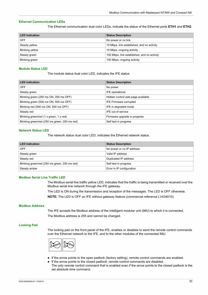
Ethernet Communication LEDs
The Ethernet communication dual color LEDs, indicate the status of the Ethernet ports ETH1 and ETH2.
Module Status LED
The module status dual color LED, indicates the IFE status.
Network Status LED
The network status dual color LED, indicates the Ethernet network status.
Modbus Serial Line Traffic LED
The Modbus serial line traffic yellow LED, indicates that the traffic is being transmitted or received over the Modbus serial line network through the IFE gateway.
The LED is ON during the transmission and reception of the messages. The LED is OFF otherwise.
NOTE: The LED is OFF on IFE without gateway feature (commercial reference LV434010).
Modbus Address
The IFE accepts the Modbus address of the intelligent modular unit (IMU) to which it is connected.
The Modbus address is 255 and cannot be changed.
Locking Pad
The locking pad on the front panel of the IFE, enables or disables to send the remote control commands over the Ethernet network to the IFE, and to the other modules of the connected IMU.
If the arrow points to the open padlock (factory setting), remote control commands are enabled. If the arrow points to the closed padlock, remote control commands are disabled.
The only remote control command that is enabled even if the arrow points to the closed padlock is the set absolute time command.
LED Indication Status Description
OFF No power or no link
Steady yellow 10 Mbps, link established, and no activity
Blinking yellow 10 Mbps, ongoing activity
Steady green 100 Mbps, link established, and no activity
Blinking green 100 Mbps, ongoing activity
LED Indication Status Description
OFF No power
Steady green IFE operational
Blinking green (250 ms ON, 250 ms OFF) Hidden control web page available
Blinking green (500 ms ON, 500 ms OFF) IFE Firmware corrupted
Blinking red (500 ms ON, 500 ms OFF) IFE in degraded mode
Steady red IFE out of service
Blinking green/red (1 s green, 1 s red) Firmware upgrade in progress
Blinking green/red (250 ms green, 250 ms red) Self test in progress
LED Indication Status Description
OFF No power or no IP address
Steady green Valid IP address
Steady red Duplicated IP address
Blinking green/red (250 ms green, 250 ms red) Self test in progress
Steady amber Error in IP configuration
DOCA0054EN-01 10/2014 33

Modbus Communication with Masterpact NT/NW and Compact NS
Test Button
The test button has two functions, according to the duration of the button pressed.
Reset Button
When the reset button is pressed for 1–5 seconds, it forces the IP acquisition mode to the factory default setting (DHCP).
ULP LED
The yellow ULP LED describes the mode of the ULP module.
Time Range Function
1–5 s Tests the connection between all the ULP modules for 15 seconds.
10–15 s Activates the hidden configuration mode for 5 minutes.
ULP LED Mode Action
Nominal None
Conflict Remove extra ULP module
Degraded Replace ULP module at the next maintenance operation
Test None
Non-critical firmware discrepancy
Upgrade firmware at the next maintenance operation
Non-critical hardware discrepancy
Replace ULP module at the next maintenance operation
Configuration discrepancy
Install missing features
Critical firmware discrepancy
Upgrade firmware
Critical hardware discrepancy
Replace ULP module
Stop Replace ULP module
Power OFF Check power supply
34 DOCA0054EN-01 10/2014

Modbus Communication with Masterpact NT/NW and Compact NS
Schematics With Masterpact NT/NW and Compact NS Circuit Breakers
Description
Depending on the type of circuit breaker used, connect the IFE Ethernet interface for LV circuit breaker to the circuit breaker using one of the following configurations: Connection of the IFE to a fixed manually-operated Compact NS circuit breaker with a BCM ULP. Connection of the IFE to a fixed electrically-operated Masterpact NT/NW or Compact NS 630b-1600
circuit breaker with a BCM ULP. Connection of the IFE to a drawout Masterpact NT/NW or Compact NS 630b-1600 circuit breaker with
a BCM ULP and its respective IO input/output interfaces for LV circuit breakers.
ULP Connection
All connection configurations require the breaker ULP cord. The insulated NSX cord is mandatory for system voltages greater than 480 Vac.
When the second ULP RJ45 connector is not used, it must be closed with a ULP terminator.
NOTICEHAZARD OF EQUIPMENT DAMAGE
The IFE RJ45 ports are for ULP modules only. Any other use can damage the IFE or the device connected to the IFE. To check if a ULP module is compatible with the IFE’s RJ45 ports, refer to the ULP System User
Guide.
Failure to follow these instructions can result in equipment damage.
DOCA0054EN-01 10/2014 35

Modbus Communication with Masterpact NT/NW and Compact NS
Connection of the IFE to a Fixed Manually-Operated Compact NS Circuit Breaker
Connect the IFE to a fixed manually-operated Compact NS circuit breaker using the breaker ULP cord:
A IFE Ethernet interface for LV circuit breakerB Breaker ULP cordC BCM ULP breaker communication moduleD Fixed manually-operated Compact NS circuit breaker
36 DOCA0054EN-01 10/2014

Modbus Communication with Masterpact NT/NW and Compact NS
Connection of the IFE to a Fixed Electrically-Operated Masterpact NT/NW or Compact NS 630b-1600 Circuit Breaker
Connect the IFE to a fixed electrically-operated Masterpact NT/NW or Compact NS 630b-1600 circuit breaker using the breaker ULP cord:
A IFE Ethernet interface for LV circuit breakerB Breaker ULP cordC Fixed terminal blockD BCM ULP breaker communication moduleE Fixed electrically-operated circuit breaker
DOCA0054EN-01 10/2014 37

Modbus Communication with Masterpact NT/NW and Compact NS
Connection of the IFE to a Drawout Masterpact NT/NW or Compact NS 630b-1600 Circuit Breaker
Connect the IFE to a drawout Masterpact NT/NW or Compact NS 630b-1600 circuit breaker using the breaker ULP cord:
A IFE Ethernet interface for LV circuit breakerB ULP cableC Breaker ULP cordD Circuit breaker disconnected position contact (CD)E Circuit breaker cradleF BCM ULP breaker communication module G Drawout circuit breakerH Drawout terminal blockI Circuit breaker connected position contact (CE)J Circuit breaker test position contact (CT)K IO input/output interface for LV circuit breaker
38 DOCA0054EN-01 10/2014

Modbus Communication with Masterpact NT/NW and Compact NS
Connection of the IFE to a Fixed or Drawout Masterpact NT/NW or Compact NS Circuit Breaker for System Voltage Greater Than 480 Vac
The following figure presents a fixed electrically-operated Masterpact NT/NW or Compact NS circuit breaker using the insulated NSX cord:
A IFE Ethernet interface for LV circuit breakerB ULP cableC Insulated ULP module for system voltage greater than 480 VacD Insulated ULP cord for system voltage greater than 480 VacE Fixed terminal blockF BCM ULP breaker communication module G Fixed electrically-operated circuit breaker
DOCA0054EN-01 10/2014 39

Modbus Communication with Masterpact NT/NW and Compact NS
40 DOCA0054EN-01 10/2014

Masterpact NT/NW, Compact NS
Modbus Protocol with Masterpact NT/NW and Compact NS
DOCA0054EN-01 10/2014
Modbus Protocol with Masterpact NT/NW and Compact NS
Chapter 2Modbus Protocol with Masterpact NT/NW and Compact NS
What Is in This Chapter?
This chapter contains the following topics:
Topic Page
Modbus Master-Slave Principle 42
Modbus Functions 45
Modbus Exception Codes 49
Write Protection 50
Password Management 51
Command Interface 52
Command Examples 56
Date Management 58
Modbus Registers Tables 59
DOCA0054EN-01 10/2014 41

Modbus Protocol with Masterpact NT/NW and Compact NS
Modbus Master-Slave Principle
Overview
The Modbus RTU protocol exchanges information using a request-reply mechanism between a master (client) and a slave (server). The master-slave principle is a model for a communication protocol in which one device (the master) controls one or more other devices (the slaves). In a standard Modbus network, there is 1 master and up to 31 slaves.
A detailed description of the Modbus protocol is available at www.modbus.org.
Characteristics of the Master-Slave Principle
The master-slave principle is characterized as follows: Only 1 master is connected to the network at a time. Only the master can initiate communication and send requests to the slaves. The master can address each slave individually using its specific address or all slaves simultaneously
using address 0. The slaves can only send replies to the master. The slaves cannot initiate communication, either to the master or to other slaves.
Master-Slave Communication Modes
The Modbus RTU protocol can exchange information using 2 communication modes: request-reply mode broadcast mode
Request-Reply Mode
In request-reply mode, the master addresses a slave using the specific address of the slave. The slave processes the request then replies to the master.
1 Request2 Process3 Reply
42 DOCA0054EN-01 10/2014

Modbus Protocol with Masterpact NT/NW and Compact NS
Broadcast Mode
The master can also address all slaves using address 0. This type of exchange is called broadcasting. The slaves do not reply to broadcasting messages.
Response Time
The response time Tr is the time needed by a slave to respond to a request sent by the master:
Values with the Modbus protocol: Typical value < 10 ms for 90% of the exchanges Maximum value is around 700 ms, so it is recommended to implement a 1 second time out after sending
a Modbus request.
Data Exchange
The Modbus protocol uses 2 types of data: bits 16-bit words called registers
Masterpact NT/NW, Compact NS, and Compact NSX circuit breakers support registers only.
Each register has a register number. Each type of data (bit or register) has a 16-bit address.
The messages exchanged with the Modbus protocol contain the address of the data to be processed.
Registers and Addresses
The address of register number n is n-1. The tables detailed in the following parts of this document provide both register numbers (in decimal format) and corresponding addresses (in hexadecimal format). For example, the address of register number 12000 is 0x2EDF (11999).
DOCA0054EN-01 10/2014 43

Modbus Protocol with Masterpact NT/NW and Compact NS
Frames
All the frames exchanged with the Modbus protocol have a maximum size of 256 bytes and are composed of 4 fields:
Field Definition Size Description
1 Slave number 1 byte Destination of the request 0: broadcasting (all slaves concerned) 1–247: unique destination
2 Function codes 1 byte or 2 bytes Refer to function codes description (see page 45)
3 Data n registers Request or reply data
NOTE: Number of registers n is limited to 52 with Micrologic E trip unit.
4 Check 2 bytes CRC16 (to check transmission errors)
44 DOCA0054EN-01 10/2014

Modbus Protocol with Masterpact NT/NW and Compact NS
Modbus Functions
General Description
The Modbus protocol offers a number of functions that are used to read or write data over the Modbus network. The Modbus protocol also offers diagnostic and network-management functions.
Only the Modbus functions handled by the circuit breaker are described here.
Read Functions
The following read functions are available:
NOTE: Number of registers n is limited to 52 with Micrologic E trip unit.
Read Register Example
The following table shows how to read the rms current on phase 1 (I1) in register 1016. The address of register 1016 is 1016 - 1 = 1015 = 0x03F7. The Modbus address of the Modbus slave is 47 = 0x2F.
The content of register 1016 (address 0x03F7) is 0x022B = 555. Therefore, the rms current on phase 1 (I1) is 555 A.
Get Date and Time Example
The following table shows how to get the date and time of a Modbus slave.The Modbus address of the Modbus slave is 47 = 0x2F.
Function Code Subfunction Code Name Description
3 (0x03) – Read holding registers Read n output or internal registers
4 (0x04) – Read input registers Read n input registers
20 (0x14) – Read file record Read the defined record in a file (see page 162)
43 (0x2B) 14 (0x0E) Read device identification Read the identification data of the slave
43 (0x2B) 15 (0x0F) Get date and time Read the date and time of the slave
43 (0x2B) 16 (0x10) Set date and time Write the date and time of the slave
Master Request Slave Reply
Field Name Example Field Name Example
Modbus slave address 0x2F Modbus slave address 0x2F
Function code 0x03 Function code 0x03
Address of the register to read (MSB) 0x03 Data length in bytes 0x02
Address of the register to read (LSB) 0xF7 Register value (MSB) 0x02
Number of registers (MSB) 0x00 Register value (LSB) 0x2B
Number of registers (LSB) 0x01 CRC (MSB) 0xXX
CRC (MSB) 0xXX CRC (LSB) 0xXX
CRC (LSB) 0xXX –
Master Request Slave Reply
Field Name Example Field Name Example
Modbus slave address 0x2F Modbus slave address 0x2F
Function code 0x2B Function code 0x2B
Subfunction code 0x0F Subfunction code 0x0F
– – Date and time Refer to the TI081 data type (see page 62).
DOCA0054EN-01 10/2014 45

Modbus Protocol with Masterpact NT/NW and Compact NS
Set Date and Time Example
The following table shows how to set date and time of a Modbus slave. The Modbus address of the Modbus slave is 47 = 0x2F, the new date is October 2, 2014, and the new time is 2:32:03:500 p.m.
NOTE: Use the broadcast mode (with Modbus slave address = 0) to set the date and time of all Modbus slaves.
The normal response is an echo of the request, returned after the date-time has been updated in the remote device. If the date-time structure content is not consistent with a true date-time (that is, an invalid date-time), the value returned in the Date-Time field is set to 0 by the device.
In case of 24 Vdc power loss, the date and time of the Modbus slaves without battery is not refreshed anymore. It is therefore mandatory to set date and time for all Modbus slaves after recovering the 24 Vdc power supply.
Furthermore, due to the clock drift of each Modbus slave, it is mandatory to set date and time for all Modbus slaves periodically. Recommended period is at least every 15 minutes.
Scattered Holding Register Read Function
The scattered holding register read function is available:
The maximum value for n is 100 but when using a Micrologic A or E trip unit, it is recommended to have n lower or equal to 21.
The scattered holding register read function enables the user to: avoid reading a large block of contiguous registers when only few registers are needed avoid multiple use of functions 3 and 4 in order to read non-contiguous registers
Master Request Slave Reply
Field Name Example Field Name Example
Modbus slave address 0x2F Modbus slave address 0x2F
Function code 0x2B Function code 0x2B
Subfunction code 0x10 Subfunction code 0x10
Reserved1 0x00 Reserved1 0x00
Not used 0x00 Not used 0x00
Year = 2014 0x0E Year = 2014 0x0E
Month = October 0x0A Month = October 0x0A
Day Of Month = 2 0x02 Day Of Month = 2 0x02
Hour = 14 0x0E Hour = 14 0x0E
Minutes = 32 0x20 Minutes = 32 0x20
3 sec. 500 ms 0x0DAC 3 sec. 502 ms 0x0DAE
Function Code Subfunction Code Name Description
100 (0x64) 4 (0x04) Read scattered holding register Read n non-contiguous registers
46 DOCA0054EN-01 10/2014

Modbus Protocol with Masterpact NT/NW and Compact NS
Read Scattered Holding Register Example
The following table shows how to read the addresses of the register 664 (address 0x0297) and register 666 (address 0x0299) of a Modbus slave. The Modbus address of the Modbus slave is 47 = 0x2F.
Write Functions
The following write functions are available:
NOTE: Number of registers n is limited to 52 with Micrologic E trip units.
Diagnostic Functions
The following diagnostic functions are available:
Master Request Slave Reply
Field Name Example Field Name Example
Modbus slave address 0x2F Modbus slave address 0x2F
Function code 0x64 Function code 0x64
Data length in bytes 0x06 Data length in bytes 0x06
Subfunction code 0x04 Subfunction code 0x04
Transmission number (1) 0xXX Transmission number (1) 0xXX
Address of first register to read (MSB) 0x02 Value of the first register read (MSB) 0x12
Address of first register to read (LSB) 0x97 Value of the first register read (LSB) 0x0A
Address of second register to read (MSB) 0x02 Value of the second register read (MSB) 0x74
Address of second register to read (LSB) 0x99 Value of the second register read (LSB) 0x0C
CRC (MSB) 0xXX CRC (MSB) 0xXX
CRC (LSB) 0xXX CRC (LSB) 0xXX
(1) The master gives the transmission number in the request. The slave returns the same number in the reply.
Function Code Subfunction Code Name Description
6 (0x06) – Preset single register Write 1 register
16 (0x10) – Preset multiple registers Write n registers
Function Code
Subfunction Code Name Description
8 (0x08) – Diagnostic Manage diagnostic counters
8 (0x08) 10 (0x0A) Clear counters and diagnostic register Reset all diagnostic counters
8 (0x08) 11 (0x0B) Return bus message counter Read the counter of correct bus messages managed by the slave
8 (0x08) 12 (0x0C) Return bus communication error counter Read the counter of incorrect bus messages managed by the slave
8 (0x08) 13 (0x0D) Return bus exception error counter Read the counter of exception responses managed by the slave
8 (0x08) 14 (0x0E) Return slave message counter Read the counter of messages sent to the slave
8 (0x08) 15 (0x0F) Return slave no response counter Read the counter of broadcast messages
8 (0x08) 16 (0x10) Return slave negative acknowledge counter Read the counter of messages sent to the slave but not answered because of the Negative Acknowledge exception code 07
8 (0x08) 17 (0x11) Return slave busy counter Read the counter of messages sent to the slave but not answered because of the Slave Device Busy exception code 06
8 (0x08) 18 (0x12) Return bus overrun counter Read the counter of incorrect bus messages due to overrun errors
11 (0x0B) – Get communication event counter Read Modbus event counter
DOCA0054EN-01 10/2014 47

Modbus Protocol with Masterpact NT/NW and Compact NS
Diagnostic Counters
Modbus uses diagnostic counters to enable performance and error management. The counters are accessible using the Modbus diagnostic functions (function codes 8 and 11). The Modbus diagnostic counters and the Modbus event counter are described in the following table:
Counters Reset
The diagnostic counters are reset to 0 when:
the maximum value 65535 is reached, they are reset by a Modbus command (function code 8, sub-function code 10), the power supply is lost, or the communication parameters are modified.
Counter Number Counter Name Description
1 Bus message counter Counter of correct bus messages managed by the slave
2 Bus communication error counter Counter of incorrect bus messages managed by the slave
3 Slave exception error counter Counter of exception responses managed by the slave and incorrect broadcast messages
4 Slave message counter Counter of messages sent to the slave
5 Slave no response counter Counter of broadcast messages
6 Slave negative acknowledge counter Counter of messages sent to the slave but not answered because of the Negative Acknowledge exception code 07
7 Slave busy count Counter of messages sent to the slave but not answered because of the Slave Device Busy exception code 06
8 Bus character overrun counter Counter of incorrect bus messages due to overrun errors
9 Comm. event counter Modbus event counter (this counter is read with function code 11)
48 DOCA0054EN-01 10/2014

Modbus Protocol with Masterpact NT/NW and Compact NS
Modbus Exception Codes
Exception Responses
Exception responses from either the master (client) or a slave (server) can result from data processing errors. One of the following events can occur after a request from the master (client):
If the slave (server) receives the request from the master (client) without a communication error and can handle the request correctly, it returns a normal response.
If the slave (server) does not receive the request from the master (client) due to a communication error, it does not return a response. The master program eventually processes a timeout condition for the request.
If the slave (server) receives the request from the master (client) but detects a communication error, it does not return a response. The master program eventually processes a timeout condition for the request.
If the slave (server) receives the request from the master (client) without a communication error, but cannot handle it (for example, the request is to read a register that does not exist), the server returns an exception response to inform the master of the nature of the error.
Exception Frame
The slave sends an exception frame to the master to report an exception response. An exception frame is composed of 4 fields:
Exception Codes
The exception response frame has 2 fields that differentiate it from a normal response frame: The exception function code of the exception response is equal to the function code of the original
request plus 128 (0x80). The exception code depends on the communication error that the slave encounters.
The following table describes the exception codes handled by the circuit breaker:
Field Definition Size Description
1 Slave number 1 byte Destination of the request 0: broadcasting (all slaves concerned) 1–247: unique destination
2 Exception function code 1 byte Request function code + 128 (0x80)
3 Exception code n bytes See next paragraph
4 Check 2 bytes CRC16 (to check transmission errors)
Exception Code Name Description
01 (0x01) Illegal function The function code received in the request is not an authorized action for the slave. The slave may be in the wrong state to process a specific request.
02 (0x02) Illegal data address The data address received by the slave is not an authorized address for the slave.
03 (0x03) Illegal data value The value in the request data field is not an authorized value for the slave.
04 (0x04) Slave device failure The slave fails to perform a requested action because of an unrecoverable error.
05 (0x05) Acknowledge The slave accepts the request but needs a long time to process it.
06 (0x06) Slave device busy The slave is busy processing another command. The master must send the request once the slave is available.
07 (0x07) Negative acknowledgment The slave cannot perform the programming request sent by the master.
08 (0x08) Memory parity error The slave detects a parity error in the memory when attending to read extended memory.
10 (0x0A) Gateway path unavailable The gateway is overloaded or not correctly configured.
11 (0x0B) Gateway target device failed to respond
The slave is not present on the network.
DOCA0054EN-01 10/2014 49

Modbus Protocol with Masterpact NT/NW and Compact NS
Write Protection
General Description
Remote modifications of Modbus registers can either be dangerous to personnel near the circuit breaker or can cause equipment damage if the protection settings are altered.Therefore, remote control commands are hardware protected (see page 20) and software protected.
Software Protection
To prevent an inadvertent change to the Micrologic trip unit configuration, remote modifications of the Modbus registers are protected by both of the following:
a robust data structure and a set of dedicated Modbus registers a multi-level password scheme
This combination is called the command interface. Failure to conform to these results in an error code and the operation is not performed. The hardware protection has always precedence over the software protection.
CAUTIONHAZARD OF NUISANCE TRIPPING OR FAILURE TO TRIP
Protection setting adjustments must be done only by trained electrical personnel.
Failure to follow these instructions can result in injury or equipment damage.
50 DOCA0054EN-01 10/2014

Modbus Protocol with Masterpact NT/NW and Compact NS
Password Management
General Description
4 passwords are defined, each one corresponding to a level.
A level is assigned to a role: Levels 1, 2, and 3 are used for general-purpose roles, like an operator role. Level 4 is the administrator level. The administrator level is required to write the settings to the
Micrologic trip units using the customer engineering tool (see page 15).
Each command via the command interface is protected by a password. The password level for each command is indicated in the description of the command.
Initial Passwords
The password values set in factory are:
Password Modification
Passwords are modified with the customer engineering tool (see page 15).
Passwords are composed of exactly 4 ASCII characters. They are case-sensitive and the allowed characters are: digits from 0 to 9 letters from a to z letters from A to Z
Password Reset
If the initial passwords have been changed, 3 cases require to reset the passwords to their factory settings with the customer engineering tool (see page 15): A password is forgotten. A new module is added in the IMU: for example, an FDM121 display for LV circuit breaker. A faulty module is replaced in the IMU.
Resetting passwords with the customer engineering tool (see page 15) is only available with the Schneider service user profile.
Password Level Factory Setting
Level 1 ‘1111’ = 0x31313131
Level 2 ‘2222’ = 0x32323232
Level 3 ‘3333’ = 0x33333333
Level 4 (administrator level) ‘0000’ = 0x30303030
DOCA0054EN-01 10/2014 51

Modbus Protocol with Masterpact NT/NW and Compact NS
Command Interface
General Description
Remote control commands are enabled when the locking pad on the IFM or IFE is in the open position. Remote modifications of the Modbus registers are performed through the command interface.
Each command has a specific code. For example, command code 904 defines the command to open the circuit breaker.
NOTE: In case of a multimaster Modbus application, the last request overrides the previous one.
Executing a Command
Follow these steps to execute a command:
Step Action
1 Load a buffer (word #0–19).
2 Write this buffer with a write request (Modbus function 16) of 20 registers, starting at register 8000.
3 Read the command status register 8021, and wait while its content shows that the command is still in progress (0x0003). If the command status does not change after a timeout (1 s), check the Modbus connection.
4 Read the command status register 8020: If content of register 8020 is the command code entered in register 8000 at step 2, go to next step. If content of register 8020 is different from the command code entered in register 8000 at step 2, restart at step 1.
5 Read the error code in the LSB of register 8021: If LSB 0, then the command failed. Check the error code to understand the cause (see next paragraph). For example, if
register 8021 returns 4609 (0x1201), then the error code is 1, which means that the password level is not correct (insufficient user rights).
If LSB = 0, then the command is executed with no errors.
52 DOCA0054EN-01 10/2014

Modbus Protocol with Masterpact NT/NW and Compact NS
Command Diagram
The following diagram shows the steps to follow in order to execute a command:
DOCA0054EN-01 10/2014 53

Modbus Protocol with Masterpact NT/NW and Compact NS
Command Data Structure
The command data structure is defined as a set of values written in registers 8000 to 8149.
The 3 main areas are: Input parameters: registers 8000 to 8015
The command-specific parameters are in registers 8006 to 8015. Command status: register 8021 Returned values: registers 8022 to 8149
Command Status
When the command terminates, the command status register 8021 contains the IMU module address (which is different from the Modbus address) and the error code:
The MSB gives the IMU module address that generates the error. When the command is sent to one IMU module, it is usually the same as the address found in the destination register. When it is sent to all IMU modules, it is the address of the first module returning an error.
The LSB gives the error code.
IMU Module Address
The following table lists the addresses of the modules:
NOTE: The Micrologic trip units of Masterpact NT/NW and Compact NS circuit breakers do not have an IMU module address.
Address Register Description Comments
0x1F3F 8000 Command code Writing at this register triggers the command using the parameters in the following registers.
0x1F40 8001 Parameter length Number of bytes used for the parameters including this one (from 10 to 30). This value is provided for each command.
0x1F41 8002 Destination A constant value provided for each command.Factory setting: 0x0000
0x1F42 8003 Reserved A constant value provided for each command (0 or 1)
0x1F430x1F44
80048005
Password The password is composed of 4 ASCII bytes.The password level to use depends on the command. This information is provided for each command.
0x1F45–0x1F4E 8006–8015 Additional parameters Additional parameters define how the command is performed. Some commands have no additional parameters.
0x1F4F 8016 Reserved Must be set to 0 (factory setting).
0x1F50 8017 Reserved Must be set to 8019 (factory setting).
0x1F51 8018 Reserved Must be set to 8020 (factory setting).
0x1F52 8019 Reserved Must be set to 8021 (factory setting).
0x1F53 8020 Last command code When the command has been executed, it holds the last command code.
0x1F54 8021 Command status When the command exits the busy state, it holds the completion code.
0x1F55 8022 Data buffer size Number of bytes returned.
0x1F56–0x1FD4 8023–8149 Data buffer Returned values. It is empty if the previous register is 0.
IMU Module Address Module
1 (0x01) Maintenance module
2 (0x02) FDM121 display for LV circuit breaker
3 (0x03) IFM Modbus-SL interface for LV circuit breaker
17 (0x11) BSCM breaker status control module for Compact NSX
18 (0x12) BCM ULP breaker communication module for Masterpact NT/NW and Compact NS
20 (0x14) Micrologic trip unit of Compact NSX
32 (0x20) IO input/output interface 1 for LV circuit breaker
33 (0x21) IO input/output interface 2 for LV circuit breaker
34 (0x22) IFE Ethernet interface for LV circuit breaker
54 DOCA0054EN-01 10/2014

Modbus Protocol with Masterpact NT/NW and Compact NS
Error Codes
The error codes listed in the following table are generic. If a module or a command generates specific errors, they are described after the corresponding command.
Error Code Description
0 (0x00) Successful command
1 (0x01) Insufficient user rights (incorrect password)
2 (0x02) Access violation: IFM locking pad is locked (see page 20)
3 (0x03) Unable to perform a read access
4 (0x04) Unable to perform a write access
5 (0x05) Unable to execute the requested service
6 (0x06) Not enough memory
7 (0x07) Allocated memory is too small
8 (0x08) Resource is not available
9 (0x09) Resource does not exist
10 (0x0A) Resource already exists
11 (0x0B) Resource is out of order
12 (0x0C) Access out of available memory
13 (0x0D) String is too long
14 (0x0E) Buffer is too small
15 (0x0F) Buffer is too large
16 (0x10) Input argument is out of range
17 (0x11) Requested security level is not supported
18 (0x12) Requested component is not supported
19 (0x13) Command is not supported
20 (0x14) Input argument has an unsupported value
21 (0x15) Internal error during command
22 (0x16) Timeout during command
23 (0x17) Checksum error during command
DOCA0054EN-01 10/2014 55

Modbus Protocol with Masterpact NT/NW and Compact NS
Command Examples
Open Circuit Breaker
The following table details the steps to perform in the master remote device to send a remote command to open the circuit breaker with the BCM ULP (see page 199). The command itself has no parameters.
Reset Energy Measurements
The following table details the steps to perform to send a command to reset the minimum/maximum energy measurements (see page 181). The command itself has one parameter.
Step Action
1 Load a buffer of 20 registers, word0 to word19. Load into word0 the value 904, the code corresponding to the open circuit breaker command. Load into word1 the value 10, the length of the input parameters. The command itself has no parameters, 10 is the length
of the fixed part. Load into word2 the value 4609 (0x1201), the destination. This value is a constant for the command. It is provided in the
command description. Load into word3 the value 1. Load into word4 and word5 the 4 ASCII bytes for the level 3 or level 4 password. Assuming this password is ‘ABcd’, load
16706 (0x4142) into word #4 and 25444 (0x6364) into word #5. Load into word6 to word16 the value 0. Load into word17 the value 8019, a command setup constant. Load into word18 the value 8020, a command setup constant. Load into word19 the value 8021, a command setup constant.
2 Write this buffer with a write request (Modbus function 16) of 20 registers, starting at register 8000.
3 Read the command status register 8021, and wait while its content shows that the command is still in progress (0x0003). If the command status does not change after a timeout (1 s), check the Modbus connection.
4 Read the command status register 8020: If content of register 8020 is the command code entered in register 8000 at step 2, go to next step. If content of register 8020 is different from the command code entered in register 8000 at step 2, restart at step 1.
5 Read the error code in the LSB of register 8021: If LSB 0, then the command failed. Check the error code to understand the cause (see next paragraph). For example,
if register 8021 returns 4609 (0x1201), then the error code is 1, which means that the password level is not correct (insufficient user rights).
If LSB = 0, then the command is executed with no errors.
Step Action
1 Load a buffer of 20 registers, word0 to word19. Load into word0 the value 46728, the code corresponding to the reset minimum/maximum command. Load into word1 the value 12, the length of the input parameters. The command itself has one parameter, add 2 bytes to
10 which is the length of the fixed part. Load into word2 the value 4609 (0x1201), the destination. This value is a constant for the command. It is provided in the
command description. Load into word3 the value 1. Load into word4 and word5 the 4 ASCII bytes for the level 3 or level 4 password. Assuming this password is ‘Pw57’, load
20599 (0x5077) into word #4 and 13623 (0x3537) into word #5. Load into word6 the value 512 (bit 9 set to one). This value requests that the energy measurement minimum/maximum be
reset. Load into word7 to word16 the value 0. Load into word17 the value 8019, a command setup constant. Load into word18 the value 8020, a command setup constant. Load into word19 the value 8021, a command setup constant.
2 Write this buffer with a write request (Modbus function 16) of 20 registers, starting at register 8000.
3 Read the command status register 8021, and wait while its content shows that the command is still in progress (0x0003). If the command status does not change after a timeout (1 s), check the Modbus connection.
4 Read the command status register 8020: If content of register 8020 is the command code entered in register 8000 at step 2, go to next step. If content of register 8020 is different from the command code entered in register 8000 at step 2, restart at step 1.
5 Read the error code in the LSB of register 8021: If LSB 0, then the command failed. Check the error code to understand the cause (see next paragraph). For example,
if register 8021 returns 4609 (0x1201), then the error code is 1, which means that the password level is not correct (insufficient user rights).
If LSB = 0, then the command was executed with no errors.
56 DOCA0054EN-01 10/2014

Modbus Protocol with Masterpact NT/NW and Compact NS
Read Date and Time
The following table details the steps to perform to send a command to read the date and time (see page 240). The command itself has no parameters.The date and time are returned in a buffer.
Step Action
1 Load a buffer of 20 registers, word0 to word19. Load into word0 the value 768, the code corresponding to the read date/time command. Load into word1 the value 10, the length of the input parameters. The command itself has no parameters, the length is the
length of the fixed part which is 10. Load into word2 the value 768 (0x0300), the destination. This value is a constant for the command. It is provided in the
command description. Load into word3 the value 0. Load into word4 and word5 the value 0x0000 (no password required). Load into word6 to word16 the value 0. Load into word17 the value 8019, a command setup constant. Load into word18 the value 8020, a command setup constant. Load into word19 the value 8021, a command setup constant.
2 Write this buffer with a write request (Modbus function 16) of 20 registers, starting at register 8000.
3 Read the command status register 8021, and wait while its content shows that the command is still in progress (0x0003). If the command status does not change after a timeout (1 s), check the Modbus connection.
4 Read the command status register 8020: If content of register 8020 is the command code entered in register 8000 at step 2, go to next step. If content of register 8020 is different from the command code entered in register 8000 at step 2, restart at step 1.
5 Read the error code in the LSB of register 8021: If LSB 0, then the command failed. Check the error code to understand the cause (see next paragraph). For example,
if register 8021 returns 783 (0x030F), then the error code is 15 (0x0F), which means that the input argument is out of range (too many parameters).
If LSB = 0, then the command was executed with no errors.
6 If there were no errors, read the data buffer length in register 8022. Its value must be 8 for this command.
7 In the data buffer: register 8023 holds the month in the MSB, the day in the LSB. register 8024 holds the year offset in the MSB (add 2000 to get the year) and the hour in the LSB. register 8025 holds the minutes in the MSB, the seconds in the LSB. register 8026 holds the milliseconds.
DOCA0054EN-01 10/2014 57

Modbus Protocol with Masterpact NT/NW and Compact NS
Date Management
Introduction
Each module of the IMU uses its date to time-stamp events and history registers.
The date of the IMU modules is updated in 2 steps:1. External synchronization: The Modbus master synchronizes the IFM or IFE communication interface.2. Internal synchronization: The IFM or IFE communication interface synchronizes all ULP modules
connected in the IMU.
External Synchronization
The user has 3 ways to externally synchronize the IFM or IFE communication interface: Manually with the customer engineering tool (see page 15). Automatically with the Modbus master using: either the Modbus set date and time request, function code 43 (0x2B) and subfunction code
16 (0x10). The Modbus request is broadcasted to several communication interfaces to synchronize them or to one specific communication interface,
or the set absolute time command to the IFM or IFE communication interface using the command interface.
The communication interface is considered as externally synchronized if the last synchronization has occurred within the last 2 hours.
Internal Synchronization
When the IFM or IFE communication interface receives the date and time, it broadcasts the date and time to all the ULP modules connected in the IMU.
58 DOCA0054EN-01 10/2014

Modbus Protocol with Masterpact NT/NW and Compact NS
Modbus Registers Tables
General Description
The following chapters describe the Modbus registers of the Micrologic trip unit and the Modbus registers of the modules connected to it. These registers provide information that can be read, like electrical measures, protection configuration, and monitoring information. The command interface enables the user to modify these registers in a controlled way.
The presentation rules of the Modbus registers are as follows: For each module, the registers are grouped in tables of logically related information, according to the
module they relate to: Micrologic trip unit (see page 98) BCM ULP breaker communication module (see page 186) IO input/output interface for LV circuit breaker (see page 202) IFM Modbus-SL interface for LV circuit breaker (see page 234) IFE Ethernet interface for LV circuit breaker (see page 244)
For some modules, the files are described separately: Micrologic trip unit (see page 160) BCM ULP breaker communication module (see page 195)
For each module, the commands are described separately: Micrologic trip unit (see page 179) BCM ULP breaker communication module (see page 197) IO input/output interface for LV circuit breaker (see page 225) IFM Modbus-SL interface for LV circuit breaker (see page 238) IFE Ethernet interface for LV circuit breaker (see page 249)
To find a register, use the ordered list of the registers with a cross reference to the page where these registers are described (see page 255).
Table Format
Register tables have the following columns:
Address: a 16-bit register address in hexadecimal. The address is the data used in the Modbus frame. Register: a 16-bit register number in decimal (register = address + 1). RW: register read-write status R: read-only access RW: read access and write access using Modbus functions RWC: read access and write access using the command interface
X: the scale factor. A scale of 10 means that the register contains the value multiplied by 10. So, the real value is the value in the register divided by 10.Example:Register 1054 contains the system frequency (see page 102). The unit is Hz and the scale factor is 10.If the register returns 503, this means that the system frequency is503/10 = 50.3 Hz.
Unit: the unit the information is expressed in. Type: the encoding data type (see data type description below). Range: the permitted values for this variable, usually a subset of what the format allows. A/E/P/H: the metering type of the Micrologic trip unit. type A (Ammeter): current measurements type E (Energy): current, voltage, power, and energy measurements type P (Power): current, voltage, power, energy measurements, and advanced protection type H (Harmonics): current, voltage, power, energy, energy quality measurements, and advanced
protection
Description: provides information about the register and restrictions that apply.
Address Register RW X Unit Type Range A/E/P/H Description
DOCA0054EN-01 10/2014 59
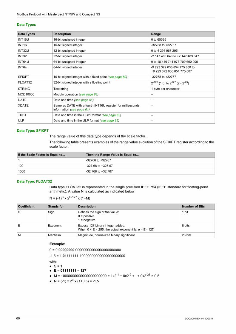
Modbus Protocol with Masterpact NT/NW and Compact NS
Data Types
Data Type: SFIXPT
The range value of this data type depends of the scale factor.
The following table presents examples of the range value evolution of the SFIXPT register according to the scale factor:
Data Type: FLOAT32
Data type FLOAT32 is represented in the single precision IEEE 754 (IEEE standard for floating-point arithmetic). A value N is calculated as indicated below:
N = (-1)S x 2E-127 x (1+M)
Example:
0 = 0 00000000 00000000000000000000000
-1.5 = 1 01111111 10000000000000000000000
with: S = 1 E = 01111111 = 127
M = 10000000000000000000000 = 1x2-1 + 0x2-2 +...+ 0x2-23 = 0.5
N = (-1) x 20 x (1+0.5) = -1.5
Data Types Description Range
INT16U 16-bit unsigned integer 0 to 65535
INT16 16-bit signed integer -32768 to +32767
INT32U 32-bit unsigned integer 0 to 4 294 967 295
INT32 32-bit signed integer -2 147 483 648 to +2 147 483 647
INT64U 64-bit unsigned integer 0 to 18 446 744 073 709 600 000
INT64 64-bit signed integer -9 223 372 036 854 775 808 to +9 223 372 036 854 775 807
SFIXPT 16-bit signed integer with a fixed point (see page 60) -32768 to +32767
FLOAT32 32-bit signed integer with a floating point 2-126 (1.0) to 2127 (2 - 2-23)
STRING Text string 1 byte per character
MOD10000 Modulo operation (see page 61) –
DATE Date and time (see page 61) –
XDATE Same as DATE with a fourth INT16U register for milliseconds information (see page 61)
–
TI081 Date and time in the TI081 format (see page 62) –
ULP Date and time in the ULP format (see page 62) –
If the Scale Factor Is Equal to... Then the Range Value Is Equal to...
1 -32768 to +32767
100 -327.68 to +327.67
1000 -32.768 to +32.767
Coefficient Stands for Description Number of Bits
S Sign Defines the sign of the value:0 = positive1 = negative
1 bit
E Exponent Excess 127 binary integer added.When 0 < E < 255, the actual exponent is: e = E - 127.
8 bits
M Mantissa Magnitude, normalized binary significant 23 bits
60 DOCA0054EN-01 10/2014

Modbus Protocol with Masterpact NT/NW and Compact NS
Data Type: MOD10000
MOD10000 corresponds to n + 1 registers in the INT16 format. Each register contains an integer from -9999 to 9999. A value V representing n + 1 registers in MOD10000 format is calculated as indicated below:
V = sum(R[x] + R[x+1] x 10000 +...+ R[x+n] x 10000n), where R[x] is the value of the register number x.
For example, to calculate the active energy Ep coded in 4 registers: register 2000 = 123 so R[x = 2000] = 123 register 2001 = 4567 register 2002 = 89 register 2003 = 0
So Ep = R[2000] + R[2001] x 100001 + R[2002] x 100002 + R[2003] x 100003
= 123 + 4567 x 10000 + 89 x 100002 + 0
= 8 945 670 123 kWh
Data Types: DATE and XDATE
This table presents DATE (registers 1 to 3) and XDATE (registers 1 to 4) data types:
For example, if the current date of BCM ULP coded in 4 registers is: register 679 = 0x0513 register 680 = 0x700A register 681 = 0x222E register 682 = 0x0358
Then the current date and time of the BCM ULP is 19/05/2012 (May 19 2012) at 10 hours, 34 minutes, 46 seconds, and 856 milliseconds.
Because: 0x0513 0x05 = 5 (months) 0x13 = 19 (days)
0x700A 0x70 = 112 (years) 0x0A = 10 (hours)
0x222E 0x22 = 34 (minutes) 0x2E = 46 (seconds)
0x0358 = 856 (milliseconds)
Register Type Bit Range Description
1 INT16U 0–7 0x01–0x1F Day
8–14 0x01–0x0C Month
15 0–1 Quality of the date and timeIf the bit 15 is set, the date and time may be incorrect. There are 2 possibilities: no synchronization with the supervisor loss of power
2 INT16U 0–7 0x00–0x17 Hours
8–15 0x50–0xC7 Year 0x50 (80) to 0x63 (99) correspond to years 1980 to 1999 0x64 (100) to 0xC7 (199) correspond to years 2000 to 2099
For example, 0x70 (112) corresponds to year 2012.
3 INT16U 0–7 0x00–0x3B Seconds
8–15 0x00–0x3B Minutes
4 INT16U 0–15 0x0000–0x03E7 Complement in milliseconds (available only for XDATE format)
DOCA0054EN-01 10/2014 61

Modbus Protocol with Masterpact NT/NW and Compact NS
Data Type: TI081
TI081 is a data type used to code date and time. This table presents the TI081 data type.
Data Type: ULP
ULP is a data type used to code date and time. This table presents the ULP data type.
ULP Date Counter
The date in ULP format is counted in number of seconds since January 1 2000.
In case of a power loss for an IMU module, the time counter is reset and will restart at January 1 2000.
If an external synchronization occurs after a power loss, the time counter is updated and converts the synchronization date to the corresponding number of seconds since January 1 2000.
Register Type Bit Range Description
1 INT16U 0–6 0x00–0x7F Year: 0x00 (00) to 0x7F (127) correspond to years 2000 to 2127For example, 0x0D (13) corresponds to year 2013.
7–15 – Reserved
2 INT16U 0–4 0x01–0x1F Day
5–7 – Reserved
8–11 0x00–0x0C Month
12–15 – Reserved
3 INT16U 0–5 0x00–0x3B Minutes
6–7 – Reserved
8–12 0x00–0x17 Hours
13–15 – Reserved
4 INT16U 0–15 0x0000–0xEA5F Milliseconds
Register Type Bit Range Description
12
INT32U – 0x00000000–0xFFFFFFFF
Number of seconds since January 1 2000
3 INT16U – – Complement in milliseconds
0–9 – Encodes the milliseconds
10–11 – Not used
12 0–1 IFM or IFE communication interface external synchronization status0 = The communication interface has not been externally synchronized within the last 2 hours.1 = The communication interface has been externally synchronized within the last 2 hours.
13 0–1 ULP module internal synchronization status0 = The ULP module has not been internally synchronized.1 = The ULP module has been internally synchronized.
14 0–1 Synchronization since last power on0 = No1 = Yes
15 – Reserved
62 DOCA0054EN-01 10/2014

Modbus Protocol with Masterpact NT/NW and Compact NS
ULP Date Conversion Principle
To convert the date from number of seconds since January 1 2000 to current date, the following rules apply:
1 non-leap year = 365 days 1 leap year = 366 days
Years 2000, 2004, 2008, 2012,...(multiple of 4) are leap years (except year 2100). 1 day = 86,400 seconds 1 hour = 3,600 seconds 1 minute = 60 seconds
The following table describes the steps to follow to convert the date from number of seconds since January 1 2000 to current date:
Step Action
1 Calculate the number of seconds since January 1 2000: S = (content of register 1 x 65536) + (content of register 2)
2 Calculate the number of days since January 1 2000: D = integer value of the quotient of S / 86,400Calculate the remaining number of seconds: s = S - (D x 86,400)
3 Calculate the number of days elapsed for the current year: d = D - (NL x 365) - (L x 366)with NL = number of non-leap years since year 2000 and L = number of leap years since year 2000
4 Calculate the number of hours: h = integer value of the quotient of s / 3600Calculate the remaining number of seconds: s’ = s - (h x 3600)
5 Calculate the number of minutes: m = integer value of the quotient of s’ / 60Calculate the remaining number of seconds: s’’ = s’ - (m x 60)
6 Calculate the number of milliseconds: ms = (content of register 3) AND 0x03FF
7 Result: The current date is date = d + 1.
For example, if d = 303, the current date corresponds to the 304th day of the year, which corresponds to October 31 2007. The current time is h:m:s’’:ms
DOCA0054EN-01 10/2014 63

Modbus Protocol with Masterpact NT/NW and Compact NS
ULP Date Conversion Example
Registers 2900 and 2901 return the date in number of seconds since January 1 2000. Register 2902 returns the complement in ms with the quality of the date.
Notes
The type column tells how many registers to read to get the variable. For instance INT16U requires reading one register, whereas INT32 requires reading 2 registers.
Some variables must be read as a block of multiple registers, like the energy measurements. Reading the block partially results in an error.
Reading from an undocumented register results in a Modbus exception (see page 49). Numerical values are given in decimal. When it is useful to have the corresponding value in
hexadecimal, it is shown as a C language type constant: 0xdddd. For example, the decimal value 123 is represented in hexadecimal as: 0x007B.
For measures that depend on the presence of neutral as identified by register 3314 (see page 151), reading the value returns 32768 (0x8000) if not applicable. For each table where it occurs, it is explained in a footnote.
INT32U or INT32 variables are stored in big-endian format: the most significant register is transmitted first, the least significant second.
Out of order and not applicable values depend on the data type.
Data Type Out of Order and Not Applicable Values
INT16U 65535 (0xFFFF)
INT16 -32768 (0x8000)
INT32U 4294967295 (0xFFFFFFFF)
INT32 0x80000000
INT64U 0xFFFFFFFFFFFFFFFF
INT64 0x8000000000000000
FLOAT32 0xFFC00000
64 DOCA0054EN-01 10/2014

Masterpact NT/NW, Compact NS
Data-Set
DOCA0054EN-01 10/2014
Data-Set
Chapter 3Data-Set
What Is in This Chapter?
This chapter contains the following sections:
Section Topic Page
3.1 Standard Data-Set 66
3.2 Legacy Data-Set 83
DOCA0054EN-01 10/2014 65

Data-Set
Standard Data-Set
Section 3.1Standard Data-Set
What Is in This Section?
This section contains the following topics:
Topic Page
Standard Data-Set 67
Modbus Registers 68
Standard Data-Set Common Registers 70
Readout Examples 81
66 DOCA0054EN-01 10/2014

Data-Set
Standard Data-Set
Description
The standard data-set is a global entity that collects the most useful information of each IMU module in one convenient table.
The benefit is that in one location the user can get up-to-date information with 3 read requests. Each module moves the data on a regular basis so that the structure is refreshed with current values.
The standard data-set can be used with IFE only.
The standard data-set is defined in the 32000 to 32341 register range.
DOCA0054EN-01 10/2014 67

Data-Set
Modbus Registers
Table of Standard Data-Set Common Registers
The main information needed for remote supervision of a Compact NSX, Compact NS, or Masterpact NT/NW circuit breaker is contained in the table of common registers starting at register 32000.
1 Modbus read request is limited to 125 registers maximum. 2 Modbus read requests are necessary to read the entire table.
It contains the following information: Circuit breaker status Tripping causes Real-time values of main measurements: current, voltage, power, energy, total harmonic distortion
The content of this table of registers is detailed in Standard Data-Set Common Registers (see page 70).
Use of these common registers is highly recommended to optimize response times and simplify the use of data.
Maintenance Data Registers
Maintenance data for a Compact NSX, Compact NS, or Masterpact NT/NW circuit breaker is not available in the table of common registers.
This must be read by specific read requests according to the type of circuit breaker.
See registers 29851 onwards for Compact NSX.
See registers 9094 onwards for Compact NS/Masterpact.
Measurement Update Period
The update period for the common registers of the standard data-set is: 1 second for the following measurements: Voltage and voltage unbalance Current and current unbalance Active, reactive, apparent, and distortion power Reactive power with harmonics Power factor and fundamental power factor Frequency
5 seconds for the following measurements: Energy Minimum and maximum real-time measurement values Total harmonic distortion (THD)
Table Format
Register tables have the following columns:
Address: a 16-bit register address in hexadecimal. The address is the data used in the Modbus frame. Register: a 16-bit register number in decimal (register = address + 1). RW: register read-write status R: read-only access RW: read access and write access using Modbus functions RWC: read access and write access using the command interface
X: the scale factor. A scale of 10 means that the register contains the value multiplied by 10. So, the real value is the value in the register divided by 10.
Unit: the unit the information is expressed in. Type: the encoding data type (see data type description below). Range: the permitted values for this variable, usually a subset of what the format allows. A/E: Types of Compact NSX Micrologic trip unit for which the register is available. Type A (Ammeter): current measurements Type E (Energy): current, voltage, power, and energy measurements
A/E/P/H: Types of Masterpact NT/NW and Compact NS Micrologic trip unit for which the register is available.
Address Register RW X Unit Type Range A/E A/E/P/H Description
68 DOCA0054EN-01 10/2014

Data-Set
Type A (Ammeter): current measurements Type E (Energy): current, voltage, power, and energy measurements Type P (Power): current, voltage, power, energy measurements, and advanced protection Type H (Harmonics): current, voltage, power, energy, energy quality measurements, and advanced
protection
Description: provides information about the register and restrictions that apply.
Data Types
Data Type: FLOAT32
Data type FLOAT32 is represented in the single precision IEEE 754 (IEEE standard for floating-point arithmetic). A value N is calculated as indicated below:
N = (-1)S x 2E-127 x (1+M)
Example:
0 = 0 00000000 00000000000000000000000
-1.5 = 1 01111111 10000000000000000000000
with: S = 1 E = 01111111 = 127
M = 10000000000000000000000 = 1x2-1 + 0x2-2 +...+ 0x2-23 = 0.5
N = (-1) x 20 x (1+0.5) = -1.5
Data Types Description Range
INT16U 16-bit unsigned integer 0 to 65535
INT64U 64-bit unsigned integer 0 to 18 446 744 073 709 600 000
FLOAT32 32-bit signed integer with a floating point 2-126 (1.0) to 2127 (2 - 2-23)
Coefficient Stands for Description Number of Bits
S Sign Defines the sign of the value:0 = positive1 = negative
1 bit
E Exponent Excess 127 binary integer added.When 0 < E < 255, the actual exponent is: e = E - 127.
8 bits
M Mantissa Magnitude, normalized binary significant 23 bits
DOCA0054EN-01 10/2014 69

Data-Set
Standard Data-Set Common Registers
Circuit Breaker Status Register
Address Register RW X Unit Type Range A/E A/E/P/H Bit Description
0x7CFF 32000 R 1 – INT16U – A/E A/E/P/H – Validity of each bit of the circuit breaker status register.
70 DOCA0054EN-01 10/2014

Data-Set
0x7D00 32001 R – – INT16U – A/E A/E/P/H – Circuit breaker status register
A/E A/E/P/H 0 OF status indication contact0 = The circuit breaker is open.1 = The circuit breaker is closed.
A/E A/E/P/H 1 SD trip indication contact0 = Circuit breaker is not tripped.1 = Circuit breaker is tripped due to electrical default, shunt trip, or push-to-trip.Bit always equal to 0 for Masterpact and Compact NS circuit breakers with motor mechanism.
A/E A/E/P/H 2 SDE fault trip indication contact0 = Circuit breaker is not tripped on electrical default.1 = Circuit breaker is tripped due to electrical default (including ground-fault test and earth-leakage test).
– A/E/P/H 3 CH spring loaded contact (only with Masterpact)0 = Spring discharged1 = Spring loadedBit always equal to 0 for Masterpact and Compact NS circuit breakers with motor mechanism.
– – 4 Reserved
– A/E/P/H 5 PF ready to close contact (only with Masterpact)0 = Not ready to close1 = Ready to closeBit always equal to 0 for Masterpact and Compact NS circuit breakers with motor mechanism.
– A/E/P/H 6 Distinction between Compact NS and Masterpact NT/NW0 = Compact NS1 = Masterpact NT/NW
– – 7–14 Reserved
A/E – 15 Data availabilityIf this bit is at 1, the circuit breaker status is not available.
Address Register RW X Unit Type Range A/E A/E/P/H Bit Description
DOCA0054EN-01 10/2014 71

Data-Set
IO Status Registers
Address Register RW X Unit Type Range A/E A/E/P/H Bit Description
0x7D01 32002 R – – INT16U – A/E A/E/P/H – Status IO 1 validity
0x7D02 32003 R – – INT16U – A/E A/E/P/H – Status IO 1
A/E A/E/P/H 0–5 Input 1–6 status
A/E A/E/P/H 6–8 Output 1–3 status
– – 9–14 Reserved
– – 15 If this bit is set, all the previous bits are not significant.
0x7D03 32004 R – – INT16U – A/E A/E/P/H – Status IO 2 validity
0x7D04 32005 R – – INT16U – A/E A/E/P/H – Status IO 2
A/E A/E/P/H 0–5 Input 1–6 status
A/E A/E/P/H 6–8 Output 1–3 status
– – 9–14 Reserved
– – 15 If this bit is set, all the previous bits are not significant.
72 DOCA0054EN-01 10/2014

Data-Set
Tripping Cause
The tripping cause register provides information about the cause of the trip for the basic protection functions. When a tripping cause bit is at 1 in the tripping cause register, it indicates that a trip has occurred and has not been reset. For Micrologic A/E trip units for Compact NSX circuit breakers, the tripping cause bit is reset by pressing
the key OK (keypad of the Micrologic A/E trip unit) twice (validation and confirmation). For Micrologic A/E/P/H trip units for Masterpact NT/NW and Compact NS circuit breakers, the tripping
cause bit is reset as soon as the circuit-breaker is closed again.
Address Register RW X Unit Type Range A/E A/E/P/H Bit Description
0x7D05 32006 R – – INT16U – A/E A/E/P/H – Validity of each bit of the tripping causes for the basic protection functions register
0x7D06 32007 R – – INT16U – A/E A/E/P/H Tripping cause for the basic protection functions
A/E A/E/P/H 0 Long-time protection Ir
A/E A/E/P/H 1 Short-time protection Isd
A/E A/E/P/H 2 Instantaneous protection Ii
A/E A/E/P/H 3 Ground-fault protection Ig
A/E A/P/H 4 Earth-leakage protection (Vigi module) In
A/E A/E/P/H 5 Integrated instantaneous protection
A/E – 6 Internal failure (STOP)
– A/E Other protections
– P/H Internal failure (temperature)
– A/E/P/H 7 Internal failure (overvoltage)
– P/H 8 Other protection (see register 32008)
A/E – 9 Instantaneous with earth-leakage protection (Vigi module) on the trip unit
E – 10 Unbalance motor protection
E – 11 Jam motor protection
E – 12 Underload motor protection
E – 13 Long-start motor protection
A/E – 14 Reflex tripping protection
A/E A/E/P/H 15 If this bit is at 1, bits 0 to 14 are not valid.
0x7D07 32008 R – – INT16U – – P/H Validity of each bit of the tripping causes for the advanced protection functions register
DOCA0054EN-01 10/2014 73

Data-Set
0x7D08 32009 R – – INT16U – – P/H – Tripping causes for the advanced protection functions
– P/H 0 Current unbalance
– P/H 1 Overcurrent on phase 1
– P/H 2 Overcurrent on phase 2
– P/H 3 Overcurrent on phase 3
– P/H 4 Overcurrent on Neutral
– P/H 5 Undervoltage
– P/H 6 Overvoltage
– P/H 7 Voltage unbalance
– P/H 8 Overpower
– P/H 9 Reverse power
– P/H 10 Underfrequency
– P/H 11 Overfrequency
– P/H 12 Phase rotation
– P/H 13 Load shedding based on current
– P/H 14 Load shedding based on power
– P/H 15 If this bit is at 1, bits 0 to 14 are not valid.
0x7D09–0x7D0C
32010–32013
– – – – – – – Reserved
Address Register RW X Unit Type Range A/E A/E/P/H Bit Description
74 DOCA0054EN-01 10/2014

Data-Set
Overrun of the Protection Setpoints
The alarm setpoint registers provide information about overrun of the standard and advanced protection setpoints. A bit is at 1 once a setpoint overrun has occurred, even if the time delay has not expired.
Address Register RW X Unit Type Range A/E A/E/P/H Bit Description
0x7D0D 32014 R – – INT16U – A/E P/H – Validity of overrun of the standard protection setpoints
0x7D0E 32015 R – – INT16U – A/E P/H – Overrun of the standard protection setpoints
A/E P/H 0 Long-time protection pick-up
– – 1–14 Reserved
A/E P/H 15 If this bit is at 1, bits 0 to 14 are not valid.
0x7D0F 32016 R – – INT16U – A/E P/H – Validity of overrun of the advanced protection setpoints
0x7D10 32017 R – – INT16U – A/E P/H – Overrun of the advanced protection setpoints
– P/H 0 Current unbalance
– P/H 1 Maximum current on phase 1
– P/H 2 Maximum current on phase 2
– P/H 3 Maximum current on phase 3
– P/H 4 Maximum current on the neutral
– P/H 5 Minimum voltage
– P/H 6 Maximum voltage
– P/H 7 Voltage unbalance
– P/H 8 Maximum power
– P/H 9 Reverse power
– P/H 10 Minimum frequency
– P/H 11 Maximum frequency
– P/H 12 Phase rotation
– P/H 13 Load shedding based on the current
– P/H 14 Load shedding based on the power
– P/H 15 If this bit is at 1, bits 0 to 14 are not valid.
0x7D11 32018 R – – INT16U – A/E P/H – Validity of advanced protection settings extended validity
0x7D12 32019 R – – INT16U – A/E P/H – Advanced protection settings extended
A/E P/H 0 Ground-fault alarm
A/E P/H 1 Earth-leakage alarm (Vigi module)
– – 2–14 Reserved
A/E P/H 15 If this bit is at 1, bits 0 to 14 are not valid.
DOCA0054EN-01 10/2014 75

Data-Set
Alarms
The alarm register provides information about the pre-alarms and the user-defined alarms. A bit is set to 1 once an alarm is active.
Current
Address Register RW X Unit Type Range A/E A/E/P/H Bit Description
0x7D13 32020 R – – INT16U – A/E – Pre-alarm extended register validity
0x7D14 32021 R – – INT16U – A/E – – Pre-alarm extended register
A/E – 0 Long-time protection time pre-alarm (PAL Ir)
A/E – 1 Earth-leakage protection pre-alarm (Vigi module) (PAL In)
A/E – 2 Ground-fault protection pre-alarm (PAL Ig)
– – 3–14 Reserved
A/E – 15 If this bit is at 1, bits 0 to 14 are not valid.
0x7D15 32022 R – – INT16U – A/E – – Validity of register of user-defined alarms
0x7D16 32023 R – – INT16U – A/E – – Register of user-defined alarms
A/E – 0 User-defined alarm 201
A/E – 1 User-defined alarm 202
A/E – 2 User-defined alarm 203
A/E – 3 User-defined alarm 204
A/E – 4 User-defined alarm 205
A/E – 5 User-defined alarm 206
A/E – 6 User-defined alarm 207
A/E – 7 User-defined alarm 208
A/E – 8 User-defined alarm 209
A/E – 9 User-defined alarm 210
– – 10–14 Reserved
A/E – 15 If this bit is at 1, bits 0 to 14 are not valid.
0x7D17–0x7D1A
32024–32027
– – – – – – – Reserved
Address Register RW X Unit Type Range A/E A/E/P/H Description
0x7D1B–0x7D1C
32028–32029
R 1 A FLOAT32 0.0–32767.0 A/E A/E/P/H RMS current on phase 1: I1
0x7D1D–0x7D1E
32030–32031
R 1 A FLOAT32 0.0–32767.0 A/E A/E/P/H RMS current on phase 2: I2
0x7D1F–0x7D20
32032–32033
R 1 A FLOAT32 0.0–32767.0 A/E A/E/P/H RMS current on phase 3: I3
0x7D21–0x7D22
32034–32035
R 1 A FLOAT32 0.0–32767.0 A/E A/E/P/H RMS current on the neutral: IN (1)
0x7D23–0x7D24
32036–32037
R 1 A FLOAT32 0.0–32767.0 A/E A/E/P/H Maximum RMS current
0x7D25–0x7D26
32038–32039
R 1 A FLOAT32 0.0–32767.0 A/E A/E/P/H Ground-fault current Ig
0x7D27–0x7D28
32040–32041
R 1 A FLOAT32 0.0–32767.0 A/E A/P/H Earth-leakage current In
(1) Value cannot be accessed for motor applications and in cases of 3-pole circuit breakers without external neutral current transformer (ENCT).
76 DOCA0054EN-01 10/2014

Data-Set
Maximum Current Values
Voltage
Frequency
When the Micrologic trip unit cannot calculate the frequency, it returns Not applicable = 0xFFC00000.
Power
Address Register RW X Unit Type Range A/E A/E/P/H Description
0x7D29–0x7D2A
32042–32043
R 1 A FLOAT32 0.0–32767.0 A/E A/E/P/H Maximum RMS current on phase 1: I1
0x7D2B–0x7D2C
32044–32045
R 1 A FLOAT32 0.0–32767.0 A/E A/E/P/H Maximum RMS current on phase 2: I2
0x7D2D–0x7D2E
32046–32047
R 1 A FLOAT32 0.0–32767.0 A/E A/E/P/H Maximum RMS current on phase 3: I3
0x7D2F–0x7D30
32048–32049
R 1 A FLOAT32 0.0–32767.0 A/E A/E/P/H Maximum RMS current on the neutral: IN (1)
0x7D31–0x7D32
32050–32051
R 1 A FLOAT32 0.0–32767.0 A/E A/E/P/H Maximum RMS current out of the 4 previous registers
0x7D33–0x7D34
32052–32053
R 1 A FLOAT32 0.0–32767.0 A/E A/E/P/H Maximum ground-fault current Ig
0x7D35–0x7D36
32054–32055
R 1 A FLOAT32 0.0–32767.0 A/E A/P/H Maximum earth-leakage current
(1) Value cannot be accessed for motor applications and in cases of 3-pole circuit breakers without external neutral current transformer (ENCT).
Address Register RW X Unit Type Range A/E A/E/P/H Description
0x7D37–0x7D38
32056–32057
R 1 V FLOAT32 0.0–1200.0
E E/P/H RMS phase-to-phase voltage V12
0x7D39–0x7D3A
32058–32059
R 1 V FLOAT32 0.0–1200.0
E E/P/H RMS phase-to-phase voltage V23
0x7D3B–0x7D3C
32060–32061
R 1 V FLOAT32 0.0–1200.0
E E/P/H RMS phase-to-phase voltage V31
0x7D3D–0x7D3E
32062–32063
R 1 V FLOAT32 0.0–1200.0
E E/P/H RMS phase-to-neutral voltage V1N (1)
0x7D3F–0x7D40
32064–32065
R 1 V FLOAT32 0.0–1200.0
E E/P/H RMS phase-to-neutral voltage V2N (1)
0x7D41–0x7D42
32066–32067
R 1 V FLOAT32 0.0–1200.0
E E/P/H RMS phase-to-neutral voltage V3N (1)
(1) Value cannot be accessed for motor applications and in cases of 3-pole circuit breakers without external neutral voltage transformer (ENVT).
Address Register RW X Unit Type Range A/E A/E/P/H Description
0x7D43–0x7D44
32068–32069
R 1 Hz FLOAT32 40.0–60.0 E P/H System frequency: F
0x7D45–0x7D46
32070–32071
R 1 Hz FLOAT32 40.0–60.0 E P/H Maximum of system frequency
Address Register RW X Unit Type Range A/E A/E/P/H Description
0x7D47–0x7D48
32072–32073
R 1 W FLOAT32 -32767000.0–+32767000.0
E P/H Active power on phase 1: P1 (1) (2)
0x7D49–0x7D4A
32074–32075
R 1 W FLOAT32 -32767000.0–+32767000.0
E P/H Active power on phase 2: P2 (1) (2)
0x7D4B–0x7D4C
32076–32077
R 1 W FLOAT32 -32767000.0–+32767000.0
E P/H Active power on phase 3: P3 (1) (2)
(1) Value cannot be accessed for motor applications and in cases of 3-pole circuit breakers without external neutral current transformer (ENCT).(2) The sign for the active and reactive power depends on the configuration of register 3316 (see page 151).
DOCA0054EN-01 10/2014 77

Data-Set
Energy
Energy is stored in big-endian format: the most significant register is transmitted first.
Current Demand Values
0x7D4D–0x7D4E
32078–32079
R 1 W FLOAT32 -32767000.0–+32767000.0
E P/H Total active power: Ptot (2)
0x7D4F–0x7D50
32080–32081
R 1 VAR FLOAT32 -32767000.0–+32767000.0
E P/H Reactive power on phase 1: Q1 (1) (2)
0x7D51–0x7D52
32082–32083
R 1 VAR FLOAT32 -32767000.0–+32767000.0
E P/H Reactive power on phase 2: Q2 (1) (2)
0x7D53–0x7D54
32084–32085
R 1 VAR FLOAT32 -32767000.0–+32767000.0
E P/H Reactive power on phase 3: Q3(1) (2)
0x7D55–0x7D56
32086–32087
R 1 VAR FLOAT32 -32767000.0–+32767000.0
E P/H Total reactive power: Qtot (2)
0x7D57–0x7D58
32088–32089
R 1 VA FLOAT32 0.0–+32767000.0 E P/H Apparent power on phase 1: S1 (1)
0x7D59–0x7D5A
32090–32091
R 1 VA FLOAT32 0.0–+32767000.0 E P/H Apparent power on phase 2: S2 (1)
0x7D5B–0x7D5C
32092–32093
R 1 VA FLOAT32 0.0–+32767000.0 E P/H Apparent power on phase 3: S3 (1)
0x7D5D–0x7D5E
32094–32095
R 1 VA FLOAT32 0.0–+32767000.0 E P/H Total apparent power: Stot
Address Register RW X Unit Type Range A/E A/E/P/H Description
(1) Value cannot be accessed for motor applications and in cases of 3-pole circuit breakers without external neutral current transformer (ENCT).(2) The sign for the active and reactive power depends on the configuration of register 3316 (see page 151).
Address Register RW X Unit Type Range A/E A/E/P/H Description
0x7D5F–0x7D62
32096–32099
R 1 Wh INT64U -1 999 999 999 000–+1 999 999 999 000
E E/P/H Active energy: Ep (1)
0x7D63–0x7D66
32100–32103
R 1 VARh INT64U -1 999 999 999 000–+1 999 999 999 000
E E/P/H Reactive energy: Eq (1)
0x7D67–0x7D6A
32104–32107
R 1 Wh INT64U 0–+1 999 999 999 000
E P/H Active energy counted positively: EpIn
0x7D6B–0x7D6E
32108–32111
R 1 Wh INT64U 0–+1 999 999 999 000
E P/H Active energy counted negatively: EpOut
0x7D6F–0x7D72
32112–32115
R 1 VARh INT64U 0–+1 999 999 999 000
E P/H Reactive energy counted positively: EqIn
0x7D73–0x7D76
32116–32119
R 1 VARh INT64U 0–+1 999 999 999 000
E P/H Reactive energy counted negatively: EqOut
0x7D77–0x7D7A
32120–32123
R 1 VAh INT64U 0–+1 999 999 999 000
E – Apparent Energy: Es
0x7D7B–0x7D7E
32124–32127
R 1 Wh INT64U 0–+1 999 999 999 000
E – Apparent energy counted positively (non-resettable): EsIn
0x7D7F–0x7D82
32128–32131
R 1 Wh INT64U 0–+1 999 999 999 000
E – Apparent energy counted negatively (non-resettable): EsOut
0x7D83–0x7D9A
32132–32155
– – – – – – – Reserved
(1) This value is always positive with Masterpact Micrologic E trip unit.
Address Register RW X Unit Type Range A/E A/E/P/H Description
0x7D9B–0x7D9C
32156–32157
R 1 A FLOAT32 0.0–32767.0 E E/P/H Current demand value on phase 1: I1 Dmd
0x7D9D–0x7D9E
32158–32159
R 1 A FLOAT32 0.0–32767.0 E E/P/H Current demand value on phase 2: I2 Dmd
(1) Value cannot be accessed for motor applications and in cases of 3-pole circuit breakers without external neutral current transformer (ENCT).
78 DOCA0054EN-01 10/2014

Data-Set
Power Demand Values
When the window is a fixed type, this value is updated at the end of the window. For the sliding type, the value is updated every 15 seconds.
Maximum Voltage Values
Register = 0 if the voltage < 25 V.
Power Factor
The sign for the fundamental power factor (cos) depends on the Micrologic trip unit configuration.
0x7D9F–0x7DA0
32160–32161
R 1 A FLOAT32 0.0–32767.0 E E/P/H Current demand value on phase 3: I3 Dmd
0x7DA1–0x7DA2
32162–32163
R 1 A FLOAT32 0.0–32767.0 E E/P/H Current demand value on the neutral: IN Dmd (1)
Address Register RW X Unit Type Range A/E A/E/P/H Description
(1) Value cannot be accessed for motor applications and in cases of 3-pole circuit breakers without external neutral current transformer (ENCT).
Address Register RW X Unit Type Range A/E A/E/P/H Description
0x7DA3–0x7DA4
32164–32165
R 1 W FLOAT32 0.0–32767000.0
E E/P/H Total active power demand: P Dmd
0x7DA5–0x7DA6
32166–32167
R 1 VAR FLOAT32 0.0–32767000.0
E P/H Total reactive power demand: Q Dmd
0x7DA7–0x7DA8
32168–32169
R 1 VA FLOAT32 0.0–32767000.0
E P/H Total apparent power demand: S Dmd
0x7DA9–0x7DC0
32170–32193
– – – – – – – Reserved
Address Register RW X Unit Type Range A/E A/E/P/H Description
0x7DC1–0x7DC2
32194–32195
R 1 V FLOAT32 0.0–1200.0
E E/P/H Maximum RMS phase-to-phase voltage V12
0x7DC3–0x7DC4
32196–32197
R 1 V FLOAT32 0.0–1200.0
E E/P/H Maximum RMS phase-to-phase voltage V23
0x7DC5–0x7DC6
32198–32199
R 1 V FLOAT32 0.0–1200.0
E E/P/H Maximum RMS phase-to-phase voltage V31
0x7DC7–0x7DC8
32200–32201
R 1 V FLOAT32 0.0–1200.0
E E/P/H Maximum RMS phase-to-neutral voltage V1N (1)
0x7DC9–0X7DCA
32202–32203
R 1 V FLOAT32 0.0–1200.0
E E/P/H Maximum RMS phase-to-neutral voltage V2N (1)
0x7DCB–0x7DCC
32204–32205
R 1 V FLOAT32 0.0–1200.0
E E/P/H Maximum RMS phase-to-neutral voltage V3N (1)
(1) Value cannot be accessed for motor applications and in cases of 3-pole circuit breakers without external neutral voltage transformer (ENVT).
Address Register RW X Unit Type Range A/E A/E/P/H Description
0x7DCD–0x7DCE
32206–32207
R 1 – FLOAT32 -1.0–+1.0
E E/P/H Power factor on phase 1: PF1 (1)
0x7DCF–0x7DD0
32208–32209
R 1 – FLOAT32 -1.0–+1.0
E E/P/H Power factor on phase 2: PF2 (1)
0x7DD1–0x7DD2
32210–32211
R 1 – FLOAT32 -1.0–+1.0
E E/P/H Power factor on phase 3: PF3 (1)
0x7DD3–0x7DD4
32212–32213
R 1 – FLOAT32 -1.0–+1.0
E E/P/H Total power factor: PF
0x7DD5–0x7DD6
32214–32215
R 1 – FLOAT32 -1.0–+1.0
E H Fundamental power factor on phase 1: cos1 (1)
0x7DD7–0x7DD8
32216–32217
R 1 – FLOAT32 -1.0–+1.0
E H Fundamental power factor on phase 2: cos2 (1)
(1) Value cannot be accessed for motor applications and in cases of 3-pole circuit breakers without external neutral voltage transformer (ENVT).
DOCA0054EN-01 10/2014 79

Data-Set
Total Harmonic Distortion (THD)
Miscellaneous
0x7DD9–0x7DDA
32218–32219
R 1 – FLOAT32 -1.0–+1.0
E H Fundamental power factor on phase 3: cos3 (1)
0x7DDB–0x7DDC
32220–32221
R 1 – FLOAT32 -1.0–+1.0
E H Total fundamental power factor: cos
Address Register RW X Unit Type Range A/E A/E/P/H Description
(1) Value cannot be accessed for motor applications and in cases of 3-pole circuit breakers without external neutral voltage transformer (ENVT).
Address Register RW X Unit Type Range A/E A/E/P/H Description
0x7DDD–0x7DDE
32222–32223
R 1 – FLOAT32 0.0–500.0 E H Total harmonic distortion of V12 compared to the fundamental
0x7DDF–0x7DE0
32224–32225
R 1 – FLOAT32 0.0–500.0 E H Total harmonic distortion of V23 compared to the fundamental
0x7DE1–0x7DE2
32226–32227
R 1 – FLOAT32 0.0–500.0 E H Total harmonic distortion of V31 compared to the fundamental
0x7DE3–0x7DE4
32228–32229
R 1 – FLOAT32 0.0–500.0 E H Total harmonic distortion of V1N compared to the fundamental (1)
0x7DE5–0x7DE6
32230–32231
R 1 – FLOAT32 0.0–500.0 E H Total harmonic distortion of V2N compared to the fundamental (1)
0x7DE7–0x7DE8
32232–32233
R 1 – FLOAT32 0.0–500.0 E H Total harmonic distortion of V3N compared to the fundamental (1)
0x7DE9– 0x7DEA
32234–32235
R 1 – FLOAT32 0.0–500.0 E H Total harmonic distortion of I1 compared to the fundamental
0x7DEB–0x7DEC
32236–32237
R 1 – FLOAT32 0.0–500.0 E H Total harmonic distortion of I2 compared to the fundamental
0x7DED–0x7DEE
32238–32239
R 1 – FLOAT32 0.0–500.0 E H Total harmonic distortion of I3 compared to the fundamental
0x7DEF– 0x7DF0
32240–32241
R 1 – FLOAT32 0.0–500.0 E H Total harmonic distortion of total current compared to the fundamental
0x7DF1– 0x7E52
32242–32339
– – – – – – – Reserved
(1) Value cannot be accessed for motor applications and in cases of 3-pole circuit breakers without external neutral voltage transformer (ENVT).
Address Register RW X Unit Type Range A/E A/E/P/H Bit Description
0x7E53 32340 R – – INT16U – A/E A/E/P/H – Validity of each bit of the inhibit close order status register
0x7E54 32341 R – – INT16U – A/E A/E/P/H – Inhibit close order status
0 Inhibit close order activated by IO
1 Inhibit close order activated by remote controller
2–15 Reserved
80 DOCA0054EN-01 10/2014

Data-Set
Readout Examples
Readout Example of a Modbus Register
The table below shows how to read the RMS current on phase 1 (I1) in registers 32028 and 32029 (coded in FLOAT32). The address of register 32028 equals 32028 - 1 = 32027 = 0x7D1B. The Modbus address of the Modbus slave is 255 = 0xFF.
The converted value of the FLOAT32 registers 32028 and 32029 is 555.
The RMS current on phase 1 (I1) is thus 555 A.
Readout Example of the Table of Standard Data-Set Common Registers
Since there are more than 125 registers in the standard data-set, at least 3 Modbus read requests are needed to read the entire table.
Request to read registers 32000 to 32123: The address of register 32000 is 0x7CFF. The length is 124 registers = 0x7C. The number of bytes is 124 x 2 = 248 bytes = 0xF8. The Modbus address of the slave is 255 = 0xFF.
Request to read registers 32124 to 32241: The address of register 32124 is 0x7D7B. The length is 118 registers = 0x76. The number of bytes is 118 x 2 = 236 bytes = 0xEC. The Modbus address of the slave is 255 = 0xFF.
Request to read registers 32340 to 32341: The address of register 32340 is 0x7E53. The length is 2 registers = 0x02. The number of bytes is 2 x 2 = 4 bytes = 0x04. The Modbus address of the slave is 255 = 0xFF.
Request from the Master Response from the Slave
Field Name Example Field Name Example
Modbus slave address 0xFF Modbus slave address 0xFF
Function code 0x03 Function code 0x03
Address of first register to be read (MSB) 0x7D Data length in bytes 0x04
Address of first register to be read (LSB) 0x1B Value read at address 0x7D1B (register 32028) 0x440A
Number of registers (MSB) 0x00 Value read at address 0x7D1C (register 32029) 0xC000
Number of registers (LSB) 0x02 CRC (MSB) 0xXX
CRC (MSB) 0xXX CRC (LSB) 0xXX
CRC (LSB) 0xXX – –
DOCA0054EN-01 10/2014 81

Data-Set
Request from the Master Response from the Slave
Field Name Example Field Name Example
Modbus slave address 0xFF Modbus slave address 0xFF
Function code 0x03 Function code 0x03
Address of the first register to be read (MSB) 0x7C Data length in bytes 0x8F
Address of the first register to be read (LSB) 0xFF Value of register 32000 (MSB) 0xXX
Number of registers (MSB) 0x00 Value of register 32000 (LSB) 0xXX
Number of registers (LSB) 0x7C Value of register 32001 (MSB) 0xXX
CRC (MSB) 0xXX Value of register 32001 (LSB) 0xXX
CRC (LSB) 0xXX – 0xXX
– – – 0xXX
– – Value of register 32123 (MSB) 0xXX
– – Value of register 32123 (LSB) 0xXX
– – CRC (MSB) 0xXX
– – CRC (LSB) 0xXX
82 DOCA0054EN-01 10/2014

Data-Set
Legacy Data-Set
Section 3.2Legacy Data-Set
What Is in This Section?
This section contains the following topics:
Topic Page
Legacy Data-Set 84
Modbus Registers 85
Legacy Data-Set Common Registers 87
Readout Examples 96
DOCA0054EN-01 10/2014 83

Data-Set
Legacy Data-Set
Description
The legacy data-set is a global entity that collects the most useful information of each IMU module in one convenient table.
The benefit is that in one location the user can get up-to-date information with 2 read requests. Each module moves the data on a regular basis so that the structure is refreshed with current values.
The legacy data-set can be used with IFM and IFE.
The legacy data-set is defined in the 12000 to12165 register range.
NOTE: The legacy data-set is compatible with previous versions of the Micrologic trip unit. For this reason, data read directly in the Modbus registers is organized in a different way than in the legacy data-set.
84 DOCA0054EN-01 10/2014

Data-Set
Modbus Registers
Table of Legacy Data-Set Common Registers
The main information needed for remote supervision of a Compact NSX, Compact NS, or Masterpact NT/NW circuit breaker is contained in the table of common registers starting at register 12000.
This compact table of 113 registers can be read with a single Modbus request.
It contains the following information: Circuit breaker status Tripping causes Real-time values of main measurements: current, voltage, power, energy, total harmonic distortion
The content of this table of registers is detailed in Legacy Data-Set Common Registers (see page 87).
Use of these common registers is highly recommended to optimize response times and simplify the use of data.
Maintenance Data Registers
Maintenance data for a Compact NSX, Compact NS, or Masterpact NT/NW circuit breaker is not available in the table of common registers.
This must be read by specific read requests according to the type of circuit breaker.
See registers 29851 onwards for Compact NSX.
See registers 9094 onwards for Compact NS/Masterpact.
Measurement Update Period
The update period for the common registers of the legacy data-set is: 1 second for the following measurements: Voltage and voltage unbalance Current and current unbalance Active, reactive, apparent, and distortion power Reactive power with harmonics Power factor and fundamental power factor Frequency
5 seconds for the following measurements: Energy Minimum and maximum real-time measurement values Total harmonic distortion (THD)
DOCA0054EN-01 10/2014 85

Data-Set
Table Format
Register tables have the following columns:
Address: a 16-bit register address in hexadecimal. The address is the data used in the Modbus frame. Register: a 16-bit register number in decimal (register = address + 1). RW: register read-write status R: read-only access RW: read access and write access using Modbus functions RWC: read access and write access using the command interface
X: the scale factor. A scale of 10 means that the register contains the value multiplied by 10. So, the real value is the value in the register divided by 10.
Unit: the unit the information is expressed in. Type: the encoding data type (see data type description below). Range: the permitted values for this variable, usually a subset of what the format allows. A/E: Types of Compact NSX Micrologic trip unit for which the register is available. Type A (Ammeter): current measurements Type E (Energy): current, voltage, power, and energy measurements
A/E/P/H: Types of Masterpact NT/NW and Compact NS Micrologic trip unit for which the register is available. Type A (Ammeter): current measurements Type E (Energy): current, voltage, power, and energy measurements Type P (Power): current, voltage, power, energy measurements, and advanced protection Type H (Harmonics): current, voltage, power, energy, energy quality measurements, and advanced
protection
Description: provides information about the register and restrictions that apply.
Data Types
Address Register RW X Unit Type Range A/E A/E/P/H Description
Data Types Description Range
INT16U 16-bit unsigned integer 0 to 65535
INT16 16-bit signed integer -32768 to +32767
INT32U 32-bit unsigned integer 0 to 4 294 967 295
INT32 32-bit signed integer -2 147 483 648 to +2 147 483 647
86 DOCA0054EN-01 10/2014

Data-Set
Legacy Data-Set Common Registers
Circuit Breaker Status Register
Address Register RW X Unit Type Range A/E A/E/P/H Bit Description
0x2EDF 12000 R 1 – INT16U – A/E A/E/P/H – Indicates the validity of each bit in the circuit breaker status register (12001).
0x2EE0 12001 R – – INT16U – A/E A/E/P/H – Circuit breaker status register
A/E A/E/P/H 0 OF status indication contact0 = The circuit breaker is open.1 = The circuit breaker is closed.
A/E A/E/P/H 1 SD trip indication contact0 = Circuit breaker is not tripped.1 = Circuit breaker is tripped due to electrical default or shunt trip or push-to-trip.Bit always equal to 0 for Masterpact and Compact NS circuit breakers with motor mechanism.
A/E A/E/P/H 2 SDE fault trip indication contact0 = Circuit breaker is not tripped on electrical default.1 = Circuit breaker is tripped due to electrical default (including ground-fault test and earth-leakage test).
– A/E/P/H 3 CH spring loaded contact (only with Masterpact)0 = Spring discharged1 = Spring loadedBit always equal to 0 for Compact NS circuit breaker.
– – 4 Reserved
– A/E/P/H 5 PF ready to close contact (only with Masterpact)0 = Not ready to close1 = Ready to closeBit always equal to 0 for Compact NS circuit breaker.
– A/E/P/H 6 Distinction between Compact NS and Masterpact NT/NW0 = Compact NS1 = Masterpact NT/NW
– – 7–14 Reserved
A/E – 15 Data availabilityIf this bit is at 1, the circuit breaker status is not available.
DOCA0054EN-01 10/2014 87

Data-Set
IO Status Registers
Tripping Cause
The tripping cause register provides information about the cause of the trip for the basic protection functions. When a tripping cause bit is at 1 in the tripping cause register, it indicates that a trip has occurred and has not been reset. For Micrologic A/E trip units for Compact NSX circuit breakers, the tripping cause bit is reset by
pressing the OK key (keypad of the Micrologic A/E trip unit) twice (validation and confirmation). For Micrologic A/E/P/H trip units for Masterpact NT/NW and Compact NS circuit breakers, the tripping
cause bit is reset as soon as the circuit-breaker is closed again.
Address Register RW X Unit Type Range A/E A/E/P/H Bit Description
0x2EE1 12002 R – – INT16U – A/E A/E/P/H – Status IO 1
A/E A/E/P/H 0–5 Input 1–6 status
A/E A/E/P/H 6–8 Output 1–3 status
A/E A/E/P/H 9–14 Reserved
A/E A/E/P/H 15 If this bit is set, all the previous bits are not significant.
0x2EE2 12003 R – – INT16U – A/E A/E/P/H – Status IO 2
A/E A/E/P/H 0–5 Input 1–6 status
A/E A/E/P/H 6–8 Output 1–3 status
A/E A/E/P/H 9–14 Reserved
A/E A/E/P/H 15 If this bit is set, all the previous bits are not significant.
Address Register RW X Unit Type Range A/E A/E/P/H Bit Description
0x2EE3 12004 R – – INT16U – A/E A/E/P/H – Tripping cause for the basic protection functions
A/E A/E/P/H 0 Long-time protection Ir
A/E A/E/P/H 1 Short-time protection Isd
A/E A/E/P/H 2 Instantaneous protection Ii
A/E A/E/P/H 3 Ground-fault protection Ig
A/E A/P/H 4 Earth-leakage protection (Vigi module) In
A/E A/E/P/H 5 Integrated instantaneous protection
A/E – 6 Internal failure (STOP)
– A/E Other protections
– P/H Internal failure (temperature)
– A/E/P/H 7 Internal failure (overvoltage)
– P/H 8 Other protection (see register 12005)
A/E – 9 Instantaneous with earth-leakage protection (Vigi module) on the trip unit
E – 10 Unbalance motor protection
E – 11 Jam motor protection
E – 12 Underload motor protection
E – 13 Long-start motor protection
A/E – 14 Reflex tripping protection
A/E A/E/P/H 15 If this bit is at 1, bits 0 to 14 are not valid.
88 DOCA0054EN-01 10/2014

Data-Set
Overrun of the Protection Setpoints
The alarm setpoint registers provide information about overrun of the standard and advanced protection setpoints. A bit is at 1 once a setpoint overrun has occurred, even if the time delay has not expired.
0x2EE4 12005 R – – INT16U – – P/H – Tripping causes for the advanced protection functions
– P/H 0 Current unbalance
– P/H 1 Overcurrent on phase 1
– P/H 2 Overcurrent on phase 2
– P/H 3 Overcurrent on phase 3
– P/H 4 Overcurrent on Neutral
– P/H 5 Undervoltage
– P/H 6 Overvoltage
– P/H 7 Voltage unbalance
– P/H 8 Overpower
– P/H 9 Reverse power
– P/H 10 Underfrequency
– P/H 11 Overfrequency
– P/H 12 Phase rotation
– P/H 13 Load shedding based on current
– P/H 14 Load shedding based on power
– P/H 15 If this bit is at 1, bits 0 to 14 are not valid.
0x2EE5– 0x2EE6
12006– 12007
– – – – – – – – Reserved
Address Register RW X Unit Type Range A/E A/E/P/H Bit Description
Address Register RW X Unit Type Range A/E A/E/P/H Bit Description
0x2EE7 12008 R – – INT16U – A/E P/H – Overrun of the standard protection setpoints
A/E P/H 0 Long-time protection pick-up
– – 1–14 Reserved
A/E P/H 15 If this bit is at 1, bits 0 to 14 are not valid.
DOCA0054EN-01 10/2014 89

Data-Set
Alarms
The alarm register provides information about the pre-alarms and the user-defined alarms. A bit is set to 1 once an alarm is active.
0x2EE8 12009 R – – INT16U – – P/H – Overrun of the advanced protection setpoints
– P/H 0 Current unbalance
– P/H 1 Maximum current on phase 1
– P/H 2 Maximum current on phase 2
– P/H 3 Maximum current on phase 3
– P/H 4 Maximum current on the neutral
– P/H 5 Minimum voltage
– P/H 6 Maximum voltage
– P/H 7 Voltage unbalance
– P/H 8 Maximum power
– P/H 9 Reverse power
– P/H 10 Minimum frequency
– P/H 11 Maximum frequency
– P/H 12 Phase rotation
– P/H 13 Load shedding based on the current
– P/H 14 Load shedding based on the power
– P/H 15 If this bit is at 1, bits 0 to 14 are not valid.
0x2EE9 12010 R – – INT16U – – E/P/H – Continuation of the previous register
– E/P/H 0 Ground-fault alarm
– E/P/H 1 Earth-leakage alarm (Vigi module)
– – 2–14 Reserved
– E/P/H 15 If this bit is at 1, bits 0 to 14 are not valid.
Address Register RW X Unit Type Range A/E A/E/P/H Bit Description
Address Register RW X Unit Type Range A/E A/E/P/H Bit Description
0x2EEA 12011 R – – INT16U – A/E – – Pre-alarm register
A/E – 0 Long-time protection time pre-alarm (PAL Ir)
A/E – 1 Earth-leakage protection pre-alarm (Vigi module) (PAL In)
A/E – 2 Ground-fault protection pre-alarm (PAL Ig)
– – 3–14 Reserved
A/E – 15 If this bit is at 1, bits 0 to 14 are not valid.
90 DOCA0054EN-01 10/2014

Data-Set
Current
Maximum Current Values
0x2EEB 12012 R – – INT16U – A/E – – Register of user-defined alarms
A/E – 0 User-defined alarm 201
A/E – 1 User-defined alarm 202
A/E – 2 User-defined alarm 203
A/E – 3 User-defined alarm 204
A/E – 4 User-defined alarm 205
A/E – 5 User-defined alarm 206
A/E – 6 User-defined alarm 207
A/E – 7 User-defined alarm 208
A/E – 8 User-defined alarm 209
A/E – 9 User-defined alarm 210
– – 10–14 Reserved
A/E – 15 If this bit is at 1, bits 0 to 14 are not valid.
0x2EEC– 0x2EEE
12013– 12015
– – – – – – – – Reserved
Address Register RW X Unit Type Range A/E A/E/P/H Bit Description
Address Register RW X Unit Type Range A/E A/E/P/H Description
0x2EEF 12016 R 1 A INT16U 0–32767 A/E A/E/P/H RMS current on phase 1: I1
0x2EF0 12017 R 1 A INT16U 0–32767 A/E A/E/P/H RMS current on phase 2: I2
0x2EF1 12018 R 1 A INT16U 0–32767 A/E A/E/P/H RMS current on phase 3: I3
0x2EF2 12019 R 1 A INT16U 0–32767 A/E A/E/P/H RMS current on the neutral: IN (1)
0x2EF3 12020 R 1 A INT16U 0–32767 A/E A/E/P/H Maximum of I1, I2, I3, and IN
0x2EF4 12021 R 1 %Ig INT16U 0–32767 A/E A/E/P/H Ground-fault current Ig (2)
0x2EF5 12022 R 1 %ln INT16U 0–32767 A/E A/P/H Earth-leakage current In (3)
(1) Value cannot be accessed for motor applications and in cases of 3-pole circuit breakers without external neutral current transformer (ENCT).(2) This value is only available: For Masterpact NT/NW and Compact NS Micrologic 6.0 trip units, expressed as %Ig pick-up For Compact NSX Micrologic 6.2 and 6.3 trip units, expressed as %Ig pick-up
(3) This value is only available: For Masterpact NT/NW and Compact NS Micrologic 7.0 trip units, expressed as %ln pick-up For Compact NSX Micrologic 7.2 and 7.3 trip units, expressed as %ln pick-up
Address Register RW X Unit Type Range A/E A/E/P/H Description
0x2EF6 12023 R 1 A INT16U 0–32767 A/E A/E/P/H Maximum RMS current on phase 1: I1
0x2EF7 12024 R 1 A INT16U 0–32767 A/E A/E/P/H Maximum RMS current on phase 2: I2
0x2EF8 12025 R 1 A INT16U 0–32767 A/E A/E/P/H Maximum RMS current on phase 3: I3
0x2EF9 12026 R 1 A INT16U 0–32767 A/E A/E/P/H Maximum RMS current on the neutral: IN (1)
(1) Value cannot be accessed for motor applications and in cases of 3-pole circuit breakers without external neutral current transformer (ENCT).(2) This value is only available: For Masterpact NT/NW and Compact NS Micrologic 6.0 trip units, expressed as %Ig pick-up For Compact NSX Micrologic 6.2 and 6.3 trip units, expressed as %Ig pick-up
(3) This value is only available: For Masterpact NT/NW and Compact NS Micrologic 7.0 trip units, expressed as %ln pick-up For Compact NSX Micrologic 7.2 and 7.3 trip units, expressed as %ln pick-up
DOCA0054EN-01 10/2014 91

Data-Set
Voltage
Frequency
When the Micrologic trip unit cannot calculate the frequency, it returns Not applicable = 32768 (0x8000).
Power
0x2EFA 12027 R 1 A INT16U 0–32767 A/E A/E/P/H Maximum RMS current out of the 4 previous registers
0x2EFB 12028 R 1 %Ig INT16U 0–32767 A/E A/E/P/H Maximum ground-fault current Ig (2)
0x2EFC 12029 R 1 %ln INT16U 0–32767 A/E A/P/H Maximum earth-leakage current (3)
Address Register RW X Unit Type Range A/E A/E/P/H Description
(1) Value cannot be accessed for motor applications and in cases of 3-pole circuit breakers without external neutral current transformer (ENCT).(2) This value is only available: For Masterpact NT/NW and Compact NS Micrologic 6.0 trip units, expressed as %Ig pick-up For Compact NSX Micrologic 6.2 and 6.3 trip units, expressed as %Ig pick-up
(3) This value is only available: For Masterpact NT/NW and Compact NS Micrologic 7.0 trip units, expressed as %ln pick-up For Compact NSX Micrologic 7.2 and 7.3 trip units, expressed as %ln pick-up
Address Register RW X Unit Type Range A/E A/E/P/H Description
0x2EFD 12030 R 1 V INT16U 0–1200 E E/P/H RMS phase-to-phase voltage V12
0x2EFE 12031 R 1 V INT16U 0–1200 E E/P/H RMS phase-to-phase voltage V23
0x2EFF 12032 R 1 V INT16U 0–1200 E E/P/H RMS phase-to-phase voltage V31
0x2F00 12033 R 1 V INT16U 0–1200 E E/P/H RMS phase-to-neutral voltage V1N (1)
0x2F01 12034 R 1 V INT16U 0–1200 E E/P/H RMS phase-to-neutral voltage V2N (1)
0x2F02 12035 R 1 V INT16U 0–1200 E E/P/H RMS phase-to-neutral voltage V3N (1)
(1) Value cannot be accessed for motor applications and in cases of 3-pole circuit breakers without external neutral voltage transformer (ENVT).
Address Register RW X Unit Type Range A/E A/E/P/H Description
0x2F03 12036 R 10 Hz INT16U 400–600 E P/H System frequency: F
0x2F04 12037 R 10 Hz INT16U 400–600 E P/H Maximum of system frequency
Address Register RW X Unit Type Range A/E A/E/P/H Description
0x2F05 12038 R 10 kW INT16 -32767–+32767 E P/H Active power on phase 1: P1 (1) (2)
0x2F06 12039 R 10 kW INT16 -32767–+32767 E P/H Active power on phase 2: P2 (1) (2)
0x2F07 12040 R 10 kW INT16 -32767–+32767 E P/H Active power on phase 3: P3 (1) (2)
0x2F08 12041 R 10 kW INT16 -32767–+32767 E P/H Total active power: Ptot (2)
0x2F09 12042 R 10 kVAR INT16 -32767–+32767 E P/H Reactive power on phase 1: Q1 (1) (2)
0x2F0A 12043 R 10 kVAR INT16 -32767–+32767 E P/H Reactive power on phase 2: Q2 (1) (2)
0x2F0B 12044 R 10 kVAR INT16 -32767–+32767 E P/H Reactive power on phase 3: Q3 (1) (2)
0x2F0C 12045 R 10 kVAR INT16 -32767–+32767 E P/H Total reactive power: Qtot (2)
0x2F0D 12046 R 10 kVA INT16U 0–32767 E P/H Apparent power on phase 1: S1 (1)
0x2F0E 12047 R 10 kVA INT16U 0–32767 E P/H Apparent power on phase 2: S2 (1)
(1) Value cannot be accessed for motor applications and in cases of 3-pole circuit breakers without external neutral current transformer (ENCT).(2) The sign for the active and reactive power depends on the configuration of register 3316 (see page 151).
92 DOCA0054EN-01 10/2014

Data-Set
Energy
Energy is stored in big-endian format: the most significant register is transmitted first, the least significant second.
Current Demand Values
Power Demand Values
When the window is fixed type, this value is updated at the end of the window. For the sliding type, the value is updated every 15 seconds.
0x2F0F 12048 R 10 kVA INT16U 0–32767 E P/H Apparent power on phase 3: S3 (1)
0x2F10 12049 R 10 kVA INT16U 0–32767 E P/H Total apparent power: Stot
Address Register RW X Unit Type Range A/E A/E/P/H Description
(1) Value cannot be accessed for motor applications and in cases of 3-pole circuit breakers without external neutral current transformer (ENCT).(2) The sign for the active and reactive power depends on the configuration of register 3316 (see page 151).
Address Register RW X Unit Type Range A/E A/E/P/H Description
0x2F11–0x2F12
12050–12051
R 1 kWh INT32 -1 999 999 999– +1 999 999 999
E E/P/H Active energy: Ep (1)
0x2F13–0x2F14
12052–12053
R 1 kVARh INT32 -1 999 999 999– +1 999 999 999
E E/P/H Reactive energy: Eq (1)
0x2F15–0x2F16
12054–12055
R 1 kWh INT32U 0–1 999 999 999 E P/H Active energy counted positively: EpIn
0x2F17–0x2F18
12056–12057
R 1 kWh INT32U 0–1 999 999 999 E P/H Active energy counted negatively: EpOut
0x2F19–0x2F1A
12058–12059
R 1 kVARh INT32U 0–1 999 999 999 E P/H Reactive energy counted positively: EqIn
0x2F1B–0x2F1C
12060–12061
R 1 kVARh INT32U 0–1 999 999 999 E P/H Reactive energy counted negatively: EqOut
0x2F1D–0x2F1E
12062–12063
R 1 kVAh INT32U 0–1 999 999 999 E E/P/H Total apparent energy: Es
0x2F1F–0x2F20
12064–12065
R 1 kWh INT32U 0–1 999 999 999 E – Active energy counted positively (non-resettable): EpIn
0x2F21–0x2F22
12066–12067
R 1 kWh INT16U 0–1 999 999 999 E – Active energy counted negatively (non-resettable): EpOut
0x2F23–0x2F2E
12068–12079
– – – – – – – Reserved
(1) This value is always positive with Masterpact Micrologic E trip units.
Address Register RW X Unit Type Range A/E A/E/P/H Description
0x2F2F 12080 R 1 A INT16U 0–32767 E E/P/H Current demand value on phase 1: I1 Dmd
0x2F30 12081 R 1 A INT16U 0–32767 E E/P/H Current demand value on phase 2: I2 Dmd
0x2F31 12082 R 1 A INT16U 0–32767 E E/P/H Current demand value on phase 3: I3 Dmd
0x2F32 12083 R 1 A INT16U 0–32767 E E/P/H Current demand value on the neutral: IN Dmd (1)
(1) Value cannot be accessed for motor applications and in cases of 3-pole circuit breakers without external neutral current transformer (ENCT).
Address Register RW X Unit Type Range A/E A/E/P/H Description
0x2F33 12084 R 10 kW INT16U 0–32767 E E/P/H Total active power demand: P Dmd
0x2F34 12085 R 10 kVAR INT16U 0–32767 E P/H Total reactive power demand: Q Dmd
DOCA0054EN-01 10/2014 93

Data-Set
Maximum Voltage Values
Register = 0 if the voltage < 25 V.
Power Factor
The sign for the fundamental power factor (cos) depends on the Micrologic trip unit configuration.
0x2F35 12086 R 10 kVA INT16U 0–32767 E P/H Total apparent power demand: S Dmd
0x2F36– 0x2F38
12087– 12089
– – – – – – – Reserved
Address Register RW X Unit Type Range A/E A/E/P/H Description
Address Register RW X Unit Type Range A/E A/E/P/H Description
0x2F39 12090 R 1 V INT16U 0–1200 E E/P/H Maximum RMS phase-to-phase voltage V12
0x2F3A 12091 R 1 V INT16U 0–1200 E E/P/H Maximum RMS phase-to-phase voltage V23
0x2F3B 12092 R 1 V INT16U 0–1200 E E/P/H Maximum RMS phase-to-phase voltage V31
0x2F3C 12093 R 1 V INT16U 0–1200 E E/P/H Maximum RMS phase-to-neutral voltage V1N (1)
0x2F3D 12094 R 1 V INT16U 0–1200 E E/P/H Maximum RMS phase-to-neutral voltage V2N (1)
0x2F3E 12095 R 1 V INT16U 0–1200 E E/P/H Maximum RMS phase-to-neutral voltage V3N (1)
(1) Value cannot be accessed for motor applications and in cases of 3-pole circuit breakers without external neutral voltage transformer (ENVT).
Address Register RW X Unit Type Range A/E A/E/P/H Description
0x2F3F 12096 R 100 – INT16 -100–+100
E E/P/H Power factor on phase 1: PF1 (1)
0x2F40 12097 R 100 – INT16 -100–+100
E E/P/H Power factor on phase 2: PF2 (1)
0x2F41 12098 R 100 – INT16 -100–+100
E E/P/H Power factor on phase 3: PF3 (1)
0x2F42 12099 R 100 – INT16 -100–+100
E E/P/H Total power factor: PF
0x2F43 12100 R 100 – INT16 -100–+100
E H Fundamental power factor on phase 1: cos1 (1)
0x2F44 12101 R 100 – INT16 -100–+100
E H Fundamental power factor on phase 2: cos2 (1)
0x2F45 12102 R 100 – INT16 -100–+100
E H Fundamental power factor on phase 3: cos3 (1)
0x2F46 12103 R 100 – INT16 -100–+100
E H Total fundamental power factor: cos
(1) Value cannot be accessed for motor applications and in cases of 3-pole circuit breakers without external neutral voltage transformer (ENVT).
94 DOCA0054EN-01 10/2014

Data-Set
Total Harmonic Distortion (THD)
Miscellaneous
Address Register RW X Unit Type Range A/E A/E/P/H Description
0x2F47 12104 R 10 % INT16U 0–5000 E H Total harmonic distortion of V12 compared to the fundamental
0x2F48 12105 R 10 % INT16U 0–5000 E H Total harmonic distortion of V23 compared to the fundamental
0x2F49 12106 R 10 % INT16U 0–5000 E H Total harmonic distortion of V31 compared to the fundamental
0x2F4A 12107 R 10 % INT16U 0–5000 E H Total harmonic distortion of V1N compared to the fundamental (1)
0x2F4B 12108 R 10 % INT16U 0–5000 E H Total harmonic distortion of V2N compared to the fundamental (1)
0x2F4C 12109 R 10 % INT16U 0–5000 E H Total harmonic distortion of V3N compared to the fundamental (1)
0x2F4D 12110 R 10 % INT16U 0–5000 E H Total harmonic distortion of I1 compared to the fundamental
0x2F4E 12111 R 10 % INT16U 0–5000 E H Total harmonic distortion of I2 compared to the fundamental
0x2F4F 12112 R 10 % INT16U 0–5000 E H Total harmonic distortion of I3 compared to the fundamental
0x2F50 12113 R 10 % INT16U 0–5000 E H Total harmonic distortion of total current compared to the fundamental
0x2F51 12114 – – – – – – – Reserved
(1) Value cannot be accessed for motor applications and in cases of 3-pole circuit breakers without external neutral voltage transformer (ENVT).
Address Register RW X Unit Type Range A/E A/E/P/H Description
0x2F7F 12160 R 1 – INT16U 0–32766 A/E A/E/P/H Trip counter
0x2F80 12161 R 1 – INT16U 0–32766 A/E A/E/P/H Counter of alarms with priority level = 3 (high)
0x2F81 12162 R 1 – INT16U 0–32766 A/E A/E/P/H Counter of alarms with priority level = 2 (medium)
0x2F82 12163 R 1 – INT16U 0–32766 A/E A/E/P/H Counter of alarms with priority level = 1 (low)
0x2F83 12164 R – – INT16U – A/E A/E/P/H Indicates the validity of each bit in the inhibit close order status register (12165)
0x2F84 12165 R – – INT16U – A/E A/E/P/H Inhibit close order status.bit 1: Inhibit close order activated by IObit 2: Inhibit close order activated by remote controllerbit 3-15: Reserved
DOCA0054EN-01 10/2014 95

Data-Set
Readout Examples
Readout Example of a Modbus Register
The table below shows how to read the rms current on phase 1 (I1) in register 12016. The address of register 12016 equals 12016 - 1 = 12015 = 0x2EEF. The Modbus address of the Modbus slave is 47 = 0x2F.
The content of register 12016 (address 0x2EEF) is 0x022B = 555.
The rms current on phase 1 (I1) is thus 555 A.
Readout Example of the Table of Legacy Data-Set Common Registers
The table below shows how to read the table of legacy data-set common registers. This table starts at register 12000 and consists of 113 registers. The address of register 12000 = 0x2EDF. The table length is 113 registers = 0x71. The number of bytes is 113x2 = 226 bytes = 0xE2. The Modbus address of the slave is 47 = 0x2F.
Request from the Master Response from the Slave
Field Name Example Field Name Example
Modbus slave address 0x2F Modbus slave address 0x2F
Function code 0x03 Function code 0x03
Address of register to be read (MSB) 0x2E Data length in bytes 0x02
Address of register to be read (LSB) 0xEF Register value (MSB) 0x02
Number of registers (MSB) 0x00 Register value (LSB) 0x2B
Number of registers (LSB) 0x01 CRC (MSB) 0xXX
CRC (MSB) 0xXX CRC (LSB) 0xXX
CRC (LSB) 0xXX – –
Request from the Master Response from the Slave
Field Name Example Field Name Example
Modbus slave address 0x2F Modbus slave address 0x2F
Function code 0x03 Function code 0x03
Address of the first register to be read (MSB) 0x2E Data length in bytes 0xE2
Address of the first register to be read (LSB) 0xDF Value of register 12000 (MSB) 0xXX
Number of registers (MSB) 0x00 Value of register 12000 (LSB) 0xXX
Number of registers (LSB) 0x71 Value of register 12001 (MSB) 0xXX
CRC (MSB) 0xXX Value of register 12001 (LSB) 0xXX
CRC (LSB) 0xXX – 0xXX
– – – 0xXX
– – Value of register 12112 (MSB) 0xXX
– – Value of register 12112 (LSB) 0xXX
– – CRC (MSB) 0xXX
– – CRC (LSB) 0xXX
96 DOCA0054EN-01 10/2014

Masterpact NT/NW, Compact NS
Micrologic Trip Unit Data for Masterpact NT/NW and Compact NS
DOCA0054EN-01 10/2014
Micrologic Trip Unit Data for Masterpact NT/NW and Compact NS
Chapter 4Micrologic Trip Unit Data for Masterpact NT/NW and Compact NS
What Is in This Chapter?
This chapter contains the following sections:
Section Topic Page
4.1 Micrologic Trip Unit Registers 98
4.2 Micrologic Trip Unit Files 160
4.3 Micrologic Trip Unit Commands 179
DOCA0054EN-01 10/2014 97

Micrologic Trip Unit Data for Masterpact NT/NW and Compact NS
Micrologic Trip Unit Registers
Section 4.1Micrologic Trip Unit Registers
What Is in This Section?
This section contains the following topics:
Topic Page
Real-Time Measurements 99
Minimum/Maximum Values of Real-Time Measurements 106
Energy Measurements 107
Demand Measurements 108
Spectral Components 110
Micrologic Trip Unit Identification 115
Status 118
Alarm History 121
Trip History 123
Analog Predefined Alarms 125
Basic Protection Parameters 129
Advanced Protection Parameters 133
Configuration of the M2C/M6C Programmable Contacts 149
Measurement Parameters 151
Time-Stamped Information 154
Maintenance Indicators 156
Miscellaneous 157
98 DOCA0054EN-01 10/2014

Micrologic Trip Unit Data for Masterpact NT/NW and Compact NS
Real-Time Measurements
General Description
The metering manager refreshes the real-time measurements every second. Real-time measurements include: voltage and voltage unbalance current and current unbalance active, reactive, apparent, and distortion power power factor and fundamental power factor frequency fundamental voltage and current fundamental active, reactive, and apparent power THD (total harmonic distortion in relation to the fundamental) thd (total harmonic distortion in relation to the RMS value) voltage to current phase shift K-factor peak factor voltage to voltage phase shift
Voltage
Voltage Unbalance
Address Register RW X Unit Type Range A/E/P/H Description
0x03E7 1000 R 1 V INT16U 0–1200 E/P/H RMS phase-to-phase voltage V12
0x03E8 1001 R 1 V INT16U 0–1200 E/P/H RMS phase-to-phase voltage V23
0x03E9 1002 R 1 V INT16U 0–1200 E/P/H RMS phase-to-phase voltage V31
0x03EA 1003 R 1 V INT16U 0–1200 E/P/H RMS phase-to-neutral voltage V1N (1)
0x03EB 1004 R 1 V INT16U 0–1200 E/P/H RMS phase-to-neutral voltage V2N (1)
0x03EC 1005 R 1 V INT16U 0–1200 E/P/H RMS phase-to-neutral voltage V3N (1)
0x03ED 1006 R 1 V INT16U 0–1200 E/P/H Arithmetic mean of V12, V23, and V31: (V12 + V23 + V31) / 3 = Vavg L-L
0x03EE 1007 R 1 V INT16U 0–1200 E/P/H Arithmetic mean of V1N, V2N, and V3N: (V1N + V2N + V3N) / 3 = Vavg L-N (1)
(1) Value is not available when the system type in register 3314 is 30 or 31. Refer to System Type (see page 151).
Address Register RW X Unit Type Range A/E/P/H Description
0x03EF 1008 R 10 % INT16 -1000–+1000
E/P/H V12 phase-to-phase voltage unbalance in relation to the arithmetic mean of phase-to-phase voltages
0x03F0 1009 R 10 % INT16 -1000–+1000
E/P/H V23 phase-to-phase voltage unbalance in relation to the arithmetic mean of phase-to-phase voltages
0x03F1 1010 R 10 % INT16 -1000–+1000
E/P/H V31 phase-to-phase voltage unbalance in relation to the arithmetic mean of phase-to-phase voltages
0x03F2 1011 R 10 % INT16 -1000–+1000
E/P/H V1N phase-to-neutral voltage unbalance in relation to the arithmetic mean of phase-to-neutral voltages (1)
0x03F3 1012 R 10 % INT16 -1000–+1000
E/P/H V2N phase-to-neutral voltage unbalance in relation to the arithmetic mean of phase-to-neutral voltages (1)
0x03F4 1013 R 10 % INT16 -1000–+1000
E/P/H V3N phase-to-neutral voltage unbalance in relation to the arithmetic mean of phase-to-neutral voltages (1)
0x03F5 1014 R 10 % INT16 -1000–+1000
E/P/H Maximum phase-to-phase voltage unbalance value of registers 1008, 1009, and 1010
(1) Value is not available when the system type in register 3314 is 30 or 31. Refer to System Type (see page 151).
DOCA0054EN-01 10/2014 99

Micrologic Trip Unit Data for Masterpact NT/NW and Compact NS
Current
Current Unbalance
Active Power
The flow sign of the active power depends on the configuration of register 3316 (see page 151).
0x03F6 1015 R 10 % INT16 -1000–+1000
E/P/H Maximum phase-to-neutral voltage unbalance value of registers 1011, 1012, and 1013 (1)
Address Register RW X Unit Type Range A/E/P/H Description
(1) Value is not available when the system type in register 3314 is 30 or 31. Refer to System Type (see page 151).
Address Register RW X Unit Type Range A/E/P/H Description
0x03F7 1016 R 1 A INT16U 0–32767 A/E/P/H RMS current on phase 1: I1
0x03F8 1017 R 1 A INT16U 0–32767 A/E/P/H RMS current on phase 2: I2
0x03F9 1018 R 1 A INT16U 0–32767 A/E/P/H RMS current on phase 3: I3
0x03FA 1019 R 1 A INT16U 0–32767 A/E/P/H RMS current on the neutral: IN (1)
0x03FB 1020 R 1 A INT16U 0–32767 A/E/P/H Maximum of I1, I2, I3, and IN
0x03FC 1021 R 1 A INT16U 0–32767 A/E/P/H Ground-fault current (2) (4)
0x03FD 1022 R 1 mA INT16U 0–32767 A/E/P/H Earth-leakage current (3) (4)
0x03FE 1023 R 1 A INT16U 0–32767 H Apparent current phase 1 (peak/2)
0x03FF 1024 R 1 A INT16U 0–32767 H Apparent current phase 2 (peak/2)
0x0400 1025 R 1 A INT16U 0–32767 H Apparent current phase 3 (peak/2)
0x0401 1026 R 1 A INT16U 0–32767 H Apparent current neutral (peak/2)
0x0402 1027 R 1 A INT16U 0–32767 E/P/H Arithmetic mean of I1, I2, and I3: (I1 + I2 + I3) / 3 = Iavg
(1) Value is not available when the system type in register 3314 is 31 or 40. Refer to System Type (see page 151).(2) Accessible only with Micrologic 5.0 P/H and 6.0 A/E/P/H trip units.(3) Accessible only with Micrologic 7.0 A/P/H trip units.(4) If this current exceeds 32767 A, the register blocks at 32767.
Address Register RW X Unit Type Range A/E/P/H Description
0x0403 1028 R 10 % INT16 -1000–+1000
E/P/H I1 current unbalance in relation to the arithmetic mean of the phase currents
0x0404 1029 R 10 % INT16 -1000–+1000
E/P/H I2 current unbalance in relation to the arithmetic mean of the phase currents
0x0405 1030 R 10 % INT16 -1000–+1000
E/P/H I3 current unbalance in relation to the arithmetic mean of the phase currents
0x0406 1031 R 10 % INT16 -1000–+1000
E/P/H IN current unbalance in relation to the arithmetic mean of the phase currents (1)
0x0407 1032 R 10 % INT16 -1000–+1000
E/P/H Maximum current unbalance of registers 1028, 1029, and 1030
(1) Value is not available when the system type in register 3314 is 31 or 40. Refer to System Type (see page 151).
Address Register RW X Unit Type Range A/E/P/H Description
0x0409 1034 R 1 kW INT16 -32767–+32767
E/P/H Active power on phase 1: P1 (1)
0x040A 1035 R 1 kW INT16 -32767–+32767
E/P/H Active power on phase 2: P2 (1)
0x040B 1036 R 1 kW INT16 -32767–+32767
E/P/H Active power on phase 3: P3 (1)
0x040C 1037 R 1 kW INT16 -32767–+32767
E/P/H Total active power: Ptot
(1) Value is not available when the system type in register 3314 is 30 or 31. Refer to System Type (see page 151).
100 DOCA0054EN-01 10/2014

Micrologic Trip Unit Data for Masterpact NT/NW and Compact NS
Reactive Power
The flow sign of the reactive power depends on the configuration of register 3316 (see page 151).
Apparent Power
Power Factor
The sign of the power factor depends on the configuration of register 3318 (see page 151).
Fundamental Power Factor (cos)
The sign of the fundamental power factor (cos) depends on the configuration of register 3318 (see page 151).
Address Register RW X Unit Type Range A/E/P/H Description
0x040D 1038 R 1 kVAR INT16 -32767–+32767
E/P/H Reactive power on phase 1: Q1 (1)
0x040E 1039 R 1 kVAR INT16 -32767–+32767
E/P/H Reactive power on phase 2: Q2 (1)
0x040F 1040 R 1 kVAR INT16 -32767–+32767
E/P/H Reactive power on phase 3: Q3 (1)
0x0410 1041 R 1 kVAR INT16 -32767–+32767
E/P/H Total reactive power: Qtot
(1) Value is not available when the system type in register 3314 is 30 or 31. Refer to System Type (see page 151).
Address Register RW X Unit Type Range A/E Description
0x0411 1042 R 1 kVA INT16U 0–32767 E/P/H Apparent power on phase 1: S1 (1)
0x0412 1043 R 1 kVA INT16U 0–32767 E/P/H Apparent power on phase 2: S2 (1)
0x0413 1044 R 1 kVA INT16U 0–32767 E/P/H Apparent power on phase 3: S3 (1)
0x0414 1045 R 1 kVA INT16U 0–32767 E/P/H Total apparent power: Stot
(1) Value is not available when the system type in register 3314 is 30 or 31. Refer to System Type (see page 151).
Address Register RW X Unit Type Range A/E/P/H Description
0x0415 1046 R 1000 – INT16 -1000–+1000
E/P/H Power factor on phase 1: PF1 (absolute value equal to |P1|/S1) (1)
0x0416 1047 R 1000 – INT16 -1000–+1000
E/P/H Power factor on phase 2: PF2 (absolute value equal to |P2|/S2) (1)
0x0417 1048 R 1000 – INT16 -1000–+1000
E/P/H Power factor on phase 3: PF3 (absolute value equal to |P3|/S3) (1)
0x0418 1049 R 1000 – INT16 -1000–+1000
E/P/H Total power factor: PF (absolute value equal to |Ptotal| / Stotal) (1)
(1) Value is not available when the system type in register 3314 is 30 or 31. Refer to System Type (see page 151).
Address Register RW X Unit Type Range A/E/P/H Description
0x0419 1050 R 1000 – INT16 -1000–+1000
H Fundamental power factor on phase 1: cos1 (absolute value equal to |P1 Fund|/S1 Fund) (1)
0x041A 1051 R 1000 – INT16 -1000–+1000
H Fundamental power factor on phase 2: cos2 (absolute value equal to |P2 Fund|/S2 Fund) (1)
0x041B 1052 R 1000 – INT16 -1000–+1000
H Fundamental power factor on phase 3: cos3 (absolute value equal to |P3 Fund|/S3 Fund) (1)
0x041C 1053 R 1000 – INT16 -1000–+1000
H Total fundamental power factor: cos (absolute value equal to |Ptot Fund|/Stot Fund)
(1) Value is not available when the system type in register 3314 is 30 or 31. Refer to System Type (see page 151).
DOCA0054EN-01 10/2014 101

Micrologic Trip Unit Data for Masterpact NT/NW and Compact NS
Frequency
When the Micrologic trip unit cannot calculate the frequency, it returns Not applicable = 32768 (0x8000).
Fundamental Voltage
Fundamental Current
Fundamental Active Power
The flow sign of the active power depends on the configuration of register 3316 (see page 151).
Fundamental Reactive Power
The flow sign of the reactive power depends on the configuration of register 3316 (see page 151).
Address Register RW X Unit Type Range A/E/P/H Description
0x041D 1054 R 10 Hz INT16U 400–600 P/H System frequency: F
Address Register RW X Unit Type Range A/E/P/H Description
0x041F 1056 R 1 V INT16U 0–1200 H Fundamental rms phase-to-phase voltage V12 Fund
0x0420 1057 R 1 V INT16U 0–1200 H Fundamental rms phase-to-phase voltage V23 Fund
0x0421 1058 R 1 V INT16U 0–1200 H Fundamental rms phase-to-phase voltage V31 Fund
0x0422 1059 R 1 V INT16U 0–1200 H Fundamental rms phase-to-neutral voltage V1N Fund (1)
0x0423 1060 R 1 V INT16U 0–1200 H Fundamental rms phase-to-neutral voltage V2N Fund (1)
0x0424 1061 R 1 V INT16U 0–1200 H Fundamental rms phase-to-neutral voltage V3N Fund (1)
(1) Value is not available when the system type in register 3314 is 30 or 31. Refer to System Type (see page 151).
Address Register RW X Unit Type Range A/E/P/H Description
0x042B 1068 R 1 A INT16U 0–32767 H Fundamental rms current on phase 1: I1 Fund
0x042C 1069 R 1 A INT16U 0–32767 H Fundamental rms current on phase 2: I2 Fund
0x042D 1070 R 1 A INT16U 0–32767 H Fundamental rms current on phase 3: I3 Fund
0x042E 1071 R 1 A INT16U 0–32767 H Fundamental rms current on neutral: IN Fund (1) (2)
(1) Value is not available when the system type in register 3314 is 31 or 40. Refer to System Type (see page 151).(2) Measured with system type 41.
Address Register RW X Unit Type Range A/E/P/H Description
0x0433 1076 R 1 kW INT16U -32767–32767
H Fundamental active power on phase 1: P1 Fund (1)
0x0434 1077 R 1 kW INT16U -32767–32767
H Fundamental active power on phase 2: P2 Fund (1)
0x0435 1078 R 1 kW INT16U -32767–32767
H Fundamental active power on phase 3: P3 Fund (1)
0x0436 1079 R 1 kW INT16U -32767–32767
H Total fundamental active power: Ptot Fund
(1) Value is not available when the system type in register 3314 is 30 or 31. Refer to System Type (see page 151).
Address Register RW X Unit Type Range A/E/P/H Description
0x0437 1080 R 1 kVAR INT16U -32767–32767
H Fundamental reactive power on phase 1: Q1 Fund (1)
(1) Value is not available when the system type in register 3314 is 30 or 31. Refer to System Type (see page 151).
102 DOCA0054EN-01 10/2014

Micrologic Trip Unit Data for Masterpact NT/NW and Compact NS
Fundamental Apparent Power
Distortion Power
Total Harmonic Distortion in Relation to the Fundamental (THD)
0x0438 1081 R 1 kVAR INT16U -32767–32767
H Fundamental reactive power on phase 2: Q2 Fund (1)
0x0439 1082 R 1 kVAR INT16U -32767–32767
H Fundamental reactive power on phase 3: Q3 Fund (1)
0x043A 1083 R 1 kVAR INT16U -32767–32767
H Total fundamental reactive power: Qtot Fund
Address Register RW X Unit Type Range A/E/P/H Description
(1) Value is not available when the system type in register 3314 is 30 or 31. Refer to System Type (see page 151).
Address Register RW X Unit Type Range A/E/P/H Description
0x043B 1084 R 1 kVA INT16U 0–32767 H Fundamental apparent power on phase 1: S1 Fund (1)
0x043C 1085 R 1 kVA INT16U 0–32767 H Fundamental apparent power on phase 2: S2 Fund (1)
0x043D 1086 R 1 kVA INT16U 0–32767 H Fundamental apparent power on phase 3: S3 Fund (1)
0x043E 1087 R 1 kVA INT16U 0–32767 H Total fundamental apparent power: Stot Fund
(1) Value is not available when the system type in register 3314 is 30 or 31. Refer to System Type (see page 151).
Address Register RW X Unit Type Range A/E/P/H Description
0x043F 1088 R 1 kVAR INT16U 0–32767 H Distortion power on phase 1: D1 (1)
0x0440 1089 R 1 kVAR INT16U 0–32767 H Distortion power on phase 2: D2 (1)
0x0441 1090 R 1 kVAR INT16U 0–32767 H Distortion power on phase 3: D3 (1)
0x0442 1091 R 1 kVAR INT16U 0–32767 H Total distortion power: Dtot
(1) Value is not available when the system type in register 3314 is 30 or 31. Refer to System Type (see page 151).
Address Register RW X Unit Type Range A/E/P/H Description
0x0443 1092 R 10 % INT16U 0–5000 H Total harmonic distortion of V12 in relation to the fundamental
0x0444 1093 R 10 % INT16U 0–5000 H Total harmonic distortion of V23 in relation to the fundamental
0x0445 1094 R 10 % INT16U 0–5000 H Total harmonic distortion of V31 in relation to the fundamental
0x0446 1095 R 10 % INT16U 0–5000 H Total harmonic distortion of V1N in relation to the fundamental (1)
0x0447 1096 R 10 % INT16U 0–5000 H Total harmonic distortion of V2N in relation to the fundamental (1)
0x0448 1097 R 10 % INT16U 0–5000 H Total harmonic distortion of V3N in relation to the fundamental (1)
0x0449 1098 R 10 % INT16U 0–5000 H Total harmonic distortion of I1 in relation to the fundamental
0x044A 1099 R 10 % INT16U 0–5000 H Total harmonic distortion of I2 in relation to the fundamental
0x044B 1100 R 10 % INT16U 0–5000 H Total harmonic distortion of I3 in relation to the fundamental
(1) Value is not available when the system type in register 3314 is 30 or 31. Refer to System Type (see page 151).(2) Measured with system type 41, calculated with system type 40.
DOCA0054EN-01 10/2014 103

Micrologic Trip Unit Data for Masterpact NT/NW and Compact NS
Total Harmonic Distortion in Relation to the RMS Value (thd)
Voltage-to-Current Phase Shift
K-Factor
0x044C 1101 R 10 % INT16U 0–5000 H Total harmonic distortion of IN in relation to the fundamental (1) (2)
Address Register RW X Unit Type Range A/E/P/H Description
(1) Value is not available when the system type in register 3314 is 30 or 31. Refer to System Type (see page 151).(2) Measured with system type 41, calculated with system type 40.
Address Register RW X Unit Type Range A/E/P/H Description
0x044D 1102 R 10 % INT16U 0–1000 H Total harmonic distortion of V12 in relation to the rms value
0x044E 1103 R 10 % INT16U 0–1000 H Total harmonic distortion of V23 in relation to the rms value
0x044F 1104 R 10 % INT16U 0–1000 H Total harmonic distortion of V31 in relation to the rms value
0x0450 1105 R 10 % INT16U 0–1000 H Total harmonic distortion of V1N in relation to the rms value (1)
0x0451 1106 R 10 % INT16U 0–1000 H Total harmonic distortion of V2N in relation to the rms value (1)
0x0452 1107 R 10 % INT16U 0–1000 H Total harmonic distortion of V3N in relation to the rms value (1)
0x0453 1108 R 10 % INT16U 0–1000 H Total harmonic distortion of I1 in relation to the rms value
0x0454 1109 R 10 % INT16U 0–1000 H Total harmonic distortion of I2 in relation to the rms value
0x0455 1110 R 10 % INT16U 0–1000 H Total harmonic distortion of I3 in relation to the rms value
0x0456 1111 R 10 % INT16U 0–1000 H Total harmonic distortion of IN in relation to the rms value (1) (2)
(1) Value is not available when the system type in register 3314 is 30 or 31. Refer to System Type (see page 151).(2) Measured with system type 41, calculated with system type 40.
Address Register RW X Unit Type Range A/E/P/H Description
0x0457 1112 R 10 Deg INT16U 0–3600 H Phase shift V12/I1 with system type 31 Phase shift V1N/I1 with system type 40
and 41
0x0458 1113 R 10 Deg INT16U 0–3600 H Phase shift V23/I2 with system type 31 Phase shift V2N/I2 with system type 40
and 41
0x0459 1114 R 10 Deg INT16U 0–3600 H Phase shift V31/I3 with system type 31 Phase shift V3N/I3 with system type 40
and 41
Address Register RW X Unit Type Range A/E/P/H Description
0x045A 1115 R 10 – INT16U 0–1000 H Phase 1 K-factor (2)
0x045B 1116 R 10 – INT16U 0–1000 H Phase 2 K-factor (2)
0x045C 1117 R 10 – INT16U 0–1000 H Phase 3 K-factor (2)
0x045D 1118 R 10 – INT16U 0–1000 H Neutral K-factor (1) (2)
(1) Value is not available when the system type in register 3314 is 30 or 31. Refer to System Type (see page 151).(2) Not applicable in 400 Hz nominal frequency system.
104 DOCA0054EN-01 10/2014

Micrologic Trip Unit Data for Masterpact NT/NW and Compact NS
Peak Factor
Voltage-to-Voltage Phase Shift
Address Register RW X Unit Type Range A/E/P/H Description
0x045E 1119 R 100 – INT16U 0–10000 H V12 voltage peak factor (3) (4)
0x045F 1120 R 100 – INT16U 0–10000 H V23 voltage peak factor (3) (4))
0x0460 1121 R 100 – INT16U 0–10000 H V31 voltage peak factor (3) (4)
0x0461 1122 R 100 – INT16U 0–10000 H V1N voltage peak factor (1) (4)
0x0462 1123 R 100 – INT16U 0–10000 H V2N voltage peak factor (1) (4)
0x0463 1124 R 100 – INT16U 0–10000 H V3N voltage peak factor (1) (4)
0x0464 1125 R 100 – INT16U 0–10000 H Phase 1 current peak factor (4)
0x0465 1126 R 100 – INT16U 0–10000 H Phase 2 current peak factor (4)
0x0466 1127 R 100 – INT16U 0–10000 H Phase 3 current peak factor (4)
0x0467 1128 R 100 – INT16U 0–10000 H Neutral current peak factor (2) (4)
(1) Value is not available when the system type in register 3314 is 30 or 31. Refer to System Type (see page 151).(2) Value is not available when the system type in register 3314 is 31 or 40. Refer to System Type (see page 151).(3) Value is not available when the system type in register 3314 is 40 or 41. Refer to System Type (see page 151).(4) Not applicable in 400 Hz nominal frequency system.
Address Register RW X Unit Type Range A/E/P/H Description
0x046C 1133 R 10 Deg INT16U 0–3600 H Phase shift V12/V12 with system type 31
Phase shift V1N/V1N with system type 40 and 41
Always equal to 0.
0x046D 1134 R 10 Deg INT16U 0–3600 H Phase shift V23/V12 with system type 31
Phase shift V2N/V1N with system type 40 and 41
Under phase balanced conditions, equals 240 degrees.
0x046E 1135 R 10 Deg INT16U 0–3600 H Phase shift V31/V12 with system type 31
Phase shift V3N/V1N with system type 40 and 41
Under phase balanced conditions, equals 120 degrees.
DOCA0054EN-01 10/2014 105

Micrologic Trip Unit Data for Masterpact NT/NW and Compact NS
Minimum/Maximum Values of Real-Time Measurements
Minimum/Maximum Measurements Rule
Minimum and maximum measurements take into account the relative value of real-time measurements. Therefore the following rule applies:
-3800<-400<0<200<600.
In this case: the minimum value = -3800 the maximum value = 600
NOTE: This rule does not apply for the power factor (PF) and for the fundamental power factor (cos):
PFmax (or cos max.) is obtained for the smallest positive value of PF (or cos). PFmin (or cos min.) is obtained for the highest negative value of PF (or cos).
The reset minimum/maximum command (command code = 46728) configures the content of the minimum/maximum real-time measurements registers.
Minimum of Real-Time Measurements
Registers 1300 to 1599 hold the minimum values of real-time metering parameters: Available only with Micrologic E, P, and H trip units. The register of the minimum value of a real-time metering parameter is equal to the register of the real-
time metering parameter plus 300.Examples: Register 1300 holds the minimum value of the phase-to-phase voltage V12 (register 1000). Register 1316 holds the minimum value of the current on phase 1 (register 1016).
The order of the registers is the same as that of the real-time metering variables. The scale factors of the minimum values are the same as those of the real-time metering parameters. The minimum values of arithmetic means and unbalance voltage (registers 1306–1315) and for
unbalance current (registers 1327 to 1332) are not available with Micrologic E trip units.
Maximum of Real-Time Measurements
Registers 1600 to 1899 hold the maximum values of real-time metering parameters: Available only with Micrologic E, P, and H trip units. The register of the maximum value of a real-time metering parameter is equal to the register of the real-
time metering parameter plus 600.Examples: Register 1600 holds the maximum value of the phase-to-phase voltage V12 (register 1000). Register 1616 holds the maximum value of the current on phase 1 (register 1016).
The order of the registers is the same as that of the real-time metering variables. The scale factors of the maximum values are the same as those of the real-time metering parameters. The maximum values of arithmetic means and unbalance voltage (registers 1606–1615) and for
unbalance current (registers 1627 to 1632) are not available with Micrologic E trip units.
106 DOCA0054EN-01 10/2014

Micrologic Trip Unit Data for Masterpact NT/NW and Compact NS
Energy Measurements
General Description
Energy measurements include: active energy Ep reactive energy Eq apparent energy Es active energy counted positively (EpIn) or negatively (EpOut), according to the configuration of register
3316 (see page 151) reactive energy counted positively (EqIn) or negatively (EqOut), according to the configuration of
register 3316 (see page 151) active energy and reactive energy are accumulated according to the configuration of register 3324
(absolute mode by factory setting) (see page 152)
NOTE:
The Micrologic E trip unit screen displays positive values (only) up to 999 999 999 kWh. Over this value, Micrologic E trip unit screen displays 999 999 999 kWh.
The Micrologic P or H trip unit screen displays positive values up to 99 999 999 kWh. Over this value, Micrologic P or H trip unit screen displays 0 and then 1 kWh.
The Micrologic P or H trip unit screen displays negative values up to -99 999 999 kWh. Over this value, Micrologic P or H trip unit screen displays 0 and then -1 kWh.
MOD10000 format is explained in the data type description (see page 61).
The behavior is the same for reactive energy and apparent energy.
Address Register RW X Unit Type Range A/E/P/H Description
0x07CF– 0x07D2
2000– 2003 RW 1 kWh MOD10000
-1016 to +1016 E/P/H Total active energy: Ep (1)
0x07D3– 0x07D6
2004– 2007 RW 1 kVARh MOD10000
-1016 to +1016 E/P/H Total reactive energy: Eq (1)
0x07D7– 0x07DA
2008– 2011 RW 1 kWh MOD10000
-1016 to +1016 P/H Active energy counted positively: EpIn
0x07DB– 0x07DE
2012– 2015 RW 1 kWh MOD10000
-1016 to +1016 P/H Active energy counted negatively: EpOut
0x07DF– 0x07E2
2016– 2019 RW 1 kVARh MOD10000
-1016 to +1016 P/H Reactive energy counted positively: EqIn
0x07E3– 0x07E6
2020– 2023 RW 1 kVARh MOD10000
-1016 to +1016 P/H Reactive energy counted negatively: EqOut
0x07E7– 0x07EA
2024– 2027 RW 1 kVAh MOD10000
-1016 to +1016 E/P/H Total apparent energy: Es
(1) Total active energy and total reactive energy are always counted positively with Micrologic E trip unit.
DOCA0054EN-01 10/2014 107

Micrologic Trip Unit Data for Masterpact NT/NW and Compact NS
Demand Measurements
General Description
Demand registers include:
current demand active, reactive, and apparent power demand
The window duration of current demand depends on the configuration of register 3352. Refer to Demand Time (see page 152).
The window duration and the window type of power demand depend on the configuration of registers 3354 and 3355. Refer to Demand Time (see page 152).
The metering manager refreshes the demand measurements every 1 minute with the sliding window type.
The metering manager refreshes the demand measurements at the end of the window interval with the block window type.
Current Demand
K-Factor Demand
Address Register RW X Unit Type Range A/E/P/H Description
0x0897 2200 R 1 A INT16U 0–32767 E/P/H Current demand on phase 1: I1 Dmd (2)
0x0898 2201 R 1 A INT16U 0–32767 E/P/H Current demand on phase 2: I2 Dmd (2)
0x0899 2202 R 1 A INT16U 0–32767 E/P/H Current demand on phase 3: I3 Dmd (2)
0x089A 2203 R 1 A INT16U 0–32767 E/P/H Current demand on the neutral: IN Dmd (1) (2)
0x089B 2204 R 1 A INT16U 0–32767 E/P/H Maximum current demand on phase 1 since the last reset: I1 Peak Dmd
0x089C 2205 R 1 A INT16U 0–32767 E/P/H Maximum current demand on phase 2 since the last reset: I2 Peak Dmd
0x089D 2206 R 1 A INT16U 0–32767 E/P/H Maximum current demand on phase 3 since the last reset: I3 Peak Dmd
0x089E 2207 R 1 A INT16U 0–32767 E/P/H Maximum current demand on the neutral since the last reset: IN Peak Dmd (1)
(1) Value is not available when the system type in register 3314 is 31 or 40. Refer to System Type (see page 151).(2) Only the thermal algorithm is available with Micrologic E trip units while Micrologic P/H trip units have both the thermal and arithmetical mean algorithms.
Address Register RW X Unit Type Range A/E/P/H Description
0x08A3 2212 R 10 – INT16U 0–1000 H K-factor demand on phase 1
0x08A4 2213 R 10 – INT16U 0–1000 H K-factor demand on phase 2
0x08A5 2214 R 10 – INT16U 0–1000 H K-factor demand on phase 3
0x08A6 2215 R 10 – INT16U 0–1000 H K-factor demand on the neutral (1)
0x08A7 2216 R 10 – INT16U 0–1000 H Maximum K-factor demand on phase 1 since last reset
0x08A8 2217 R 10 – INT16U 0–1000 H Maximum K-factor demand on phase 2 since last reset
0x08A9 2218 R 10 – INT16U 0–1000 H Maximum K-factor demand on phase 3 since last reset
0x08AA 2219 R 10 – INT16U 0–1000 H Maximum K-factor demand on the neutral since last reset (1)
(1) Value is not available when the system type in register 3314 is 31 or 40. Refer to System Type (see page 151).
108 DOCA0054EN-01 10/2014

Micrologic Trip Unit Data for Masterpact NT/NW and Compact NS
Active Power Demand
Reactive Power Demand
Apparent Power Demand
Address Register RW X Unit Type Range A/E/P/H Description
0x08AF 2224 R 1 kW INT16U 0–32767 E/P/H Total active power demand: P Dmd (1) (3)
0x08B0 2225 R 1 kW INT16U 0–32767 E/P/H Maximum total active power demand since the last reset: P Peak Dmd
0x08B1 2226 R 1 kW INT16U 0–32767 P/H Predicted active power demand at the end of the window (2)
0x08B2 2227 R 1000 – INT16 -1000–+1000
P/H Total power factor at last active power demand maximum
0x08B3 2228 R 1 kVAR INT16U 0–32767 P/H Reactive power demand at last active power demand maximum
0x08B4 2229 R 1 kVA INT16U 0–32767 P/H Apparent power demand at last active power demand maximum
(1) For the block window type, this value is updated at the end of the window interval. For the sliding window type, the value is updated every 15 seconds.(2) Value is updated every 15 seconds for both block window and sliding window types.(3) Only the thermal algorithm is available with Micrologic E trip units while Micrologic P/H trip units have both the thermal and arithmetical mean algorithms.
Address Register RW X Unit Type Range A/E/P/H Description
0x08B5 2230 R 1 kVAR INT16U 0–32767 P/H Total reactive power demand: Q Dmd (1)
0x08B6 2231 R 1 kVAR INT16U 0–32767 P/H Reactive power demand maximum since the last reset: Q Peak Dmd
0x08B7 2232 R 1 kVAR INT16U 0–32767 P/H Predicted reactive power demand at the end of the window (2)
0x08B8 2233 R 1000 – INT16 -1000–+1000
P/H Total power factor at last reactive power demand maximum
0x08B9 2234 R 1 kW INT16U 0–32767 P/H Active power demand at last reactive power demand maximum
0x08BA 2235 R 1 kVA INT16U 0–32767 P/H Apparent power demand at last reactive power demand maximum
(1) For the block window type, this value is updated at the end of the window interval. For the sliding window type, the value is updated every 15 seconds.(2) Value is updated every 15 seconds for both block window and sliding window types.
Address Register RW X Unit Type Range A/E/P/H Description
0x08BB 2236 R 1 kVA INT16U 0–32767 E/P/H Total apparent power demand: S Dmd (1)
0x08BC 2237 R 1 kVA INT16U 0–32767 E/P/H Maximum total apparent power demand since last reset: S Peak Dmd
0x08BD 2238 R 1 kVA INT16U 0–32767 P/H Predicted apparent power demand at the end of the window (2)
0x08BE 2239 R 1000 – INT16 -1000–+1000
P/H Total power factor at last apparent power demand maximum
0x08BF 2240 R 1 kW INT16U 0–32767 P/H Active power demand at last apparent power demand maximum
0x08C0 2241 R 1 kVAR INT16U 0–32767 P/H Reactive power demand at last apparent power demand maximum
(1) For the block window type, this value is updated at the end of the window interval. For the sliding window type, the value is updated every 15 seconds.(2) Value is updated every 15 seconds for both block window and sliding window types.
DOCA0054EN-01 10/2014 109
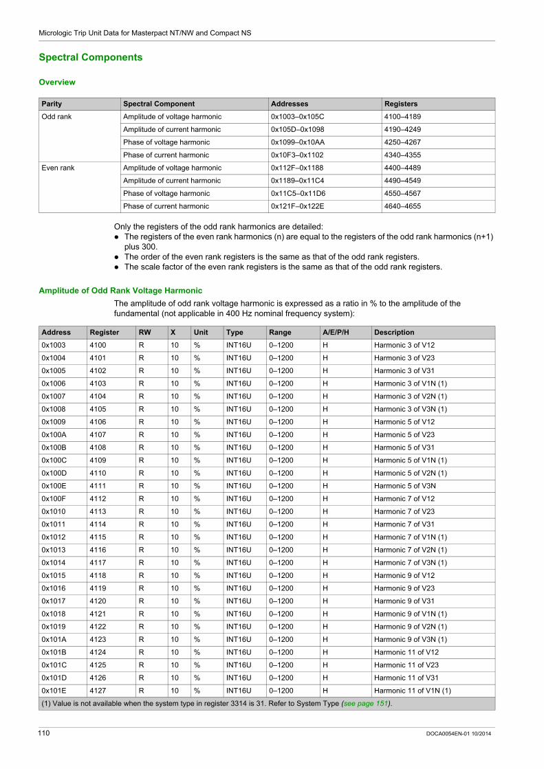
Micrologic Trip Unit Data for Masterpact NT/NW and Compact NS
Spectral Components
Overview
Only the registers of the odd rank harmonics are detailed: The registers of the even rank harmonics (n) are equal to the registers of the odd rank harmonics (n+1)
plus 300. The order of the even rank registers is the same as that of the odd rank registers. The scale factor of the even rank registers is the same as that of the odd rank registers.
Amplitude of Odd Rank Voltage Harmonic
The amplitude of odd rank voltage harmonic is expressed as a ratio in % to the amplitude of the fundamental (not applicable in 400 Hz nominal frequency system):
Parity Spectral Component Addresses Registers
Odd rank Amplitude of voltage harmonic 0x1003–0x105C 4100–4189
Amplitude of current harmonic 0x105D–0x1098 4190–4249
Phase of voltage harmonic 0x1099–0x10AA 4250–4267
Phase of current harmonic 0x10F3–0x1102 4340–4355
Even rank Amplitude of voltage harmonic 0x112F–0x1188 4400–4489
Amplitude of current harmonic 0x1189–0x11C4 4490–4549
Phase of voltage harmonic 0x11C5–0x11D6 4550–4567
Phase of current harmonic 0x121F–0x122E 4640–4655
Address Register RW X Unit Type Range A/E/P/H Description
0x1003 4100 R 10 % INT16U 0–1200 H Harmonic 3 of V12
0x1004 4101 R 10 % INT16U 0–1200 H Harmonic 3 of V23
0x1005 4102 R 10 % INT16U 0–1200 H Harmonic 3 of V31
0x1006 4103 R 10 % INT16U 0–1200 H Harmonic 3 of V1N (1)
0x1007 4104 R 10 % INT16U 0–1200 H Harmonic 3 of V2N (1)
0x1008 4105 R 10 % INT16U 0–1200 H Harmonic 3 of V3N (1)
0x1009 4106 R 10 % INT16U 0–1200 H Harmonic 5 of V12
0x100A 4107 R 10 % INT16U 0–1200 H Harmonic 5 of V23
0x100B 4108 R 10 % INT16U 0–1200 H Harmonic 5 of V31
0x100C 4109 R 10 % INT16U 0–1200 H Harmonic 5 of V1N (1)
0x100D 4110 R 10 % INT16U 0–1200 H Harmonic 5 of V2N (1)
0x100E 4111 R 10 % INT16U 0–1200 H Harmonic 5 of V3N
0x100F 4112 R 10 % INT16U 0–1200 H Harmonic 7 of V12
0x1010 4113 R 10 % INT16U 0–1200 H Harmonic 7 of V23
0x1011 4114 R 10 % INT16U 0–1200 H Harmonic 7 of V31
0x1012 4115 R 10 % INT16U 0–1200 H Harmonic 7 of V1N (1)
0x1013 4116 R 10 % INT16U 0–1200 H Harmonic 7 of V2N (1)
0x1014 4117 R 10 % INT16U 0–1200 H Harmonic 7 of V3N (1)
0x1015 4118 R 10 % INT16U 0–1200 H Harmonic 9 of V12
0x1016 4119 R 10 % INT16U 0–1200 H Harmonic 9 of V23
0x1017 4120 R 10 % INT16U 0–1200 H Harmonic 9 of V31
0x1018 4121 R 10 % INT16U 0–1200 H Harmonic 9 of V1N (1)
0x1019 4122 R 10 % INT16U 0–1200 H Harmonic 9 of V2N (1)
0x101A 4123 R 10 % INT16U 0–1200 H Harmonic 9 of V3N (1)
0x101B 4124 R 10 % INT16U 0–1200 H Harmonic 11 of V12
0x101C 4125 R 10 % INT16U 0–1200 H Harmonic 11 of V23
0x101D 4126 R 10 % INT16U 0–1200 H Harmonic 11 of V31
0x101E 4127 R 10 % INT16U 0–1200 H Harmonic 11 of V1N (1)
(1) Value is not available when the system type in register 3314 is 31. Refer to System Type (see page 151).
110 DOCA0054EN-01 10/2014

Micrologic Trip Unit Data for Masterpact NT/NW and Compact NS
0x101F 4128 R 10 % INT16U 0–1200 H Harmonic 11 of V2N (1)
0x1020 4129 R 10 % INT16U 0–1200 H Harmonic 11 of V3N (1)
0x1021 4130 R 10 % INT16U 0–1200 H Harmonic 13 of V12
0x1022 4131 R 10 % INT16U 0–1200 H Harmonic 13 of V23
0x1023 4132 R 10 % INT16U 0–1200 H Harmonic 13 of V31
0x1024 4133 R 10 % INT16U 0–1200 H Harmonic 13 of V1N (1)
0x1025 4134 R 10 % INT16U 0–1200 H Harmonic 13 of V2N (1)
0x1026 4135 R 10 % INT16U 0–1200 H Harmonic 13 of V3N (1)
0x1027 4136 R 10 % INT16U 0–1200 H Harmonic 15 of V12
0x1028 4137 R 10 % INT16U 0–1200 H Harmonic 15 of V23
0x1029 4138 R 10 % INT16U 0–1200 H Harmonic 15 of V31
0x102A 4139 R 10 % INT16U 0–1200 H Harmonic 15 of V1N (1)
0x102B 4140 R 10 % INT16U 0–1200 H Harmonic 15 of V2N (1)
0x102C 4141 R 10 % INT16U 0–1200 H Harmonic 15 of V3N (1)
0x102D 4142 R 10 % INT16U 0–1200 H Harmonic 17 of V12
0x102E 4143 R 10 % INT16U 0–1200 H Harmonic 17 of V23
0x102F 4144 R 10 % INT16U 0–1200 H Harmonic 17 of V31
0x1030 4145 R 10 % INT16U 0–1200 H Harmonic 17 of V1N (1)
0x1031 4146 R 10 % INT16U 0–1200 H Harmonic 17 of V2N (1)
0x1032 4147 R 10 % INT16U 0–1200 H Harmonic 17 of V3N (1)
0x1033 4148 R 10 % INT16U 0–1200 H Harmonic 19 of V12
0x1034 4149 R 10 % INT16U 0–1200 H Harmonic 19 of V23
0x1035 4150 R 10 % INT16U 0–1200 H Harmonic 19 of V31
0x1036 4151 R 10 % INT16U 0–1200 H Harmonic 19 of V1N (1)
0x1037 4152 R 10 % INT16U 0–1200 H Harmonic 19 of V2N (1)
0x1038 4153 R 10 % INT16U 0–1200 H Harmonic 19 of V3N (1)
0x1039 4154 R 10 % INT16U 0–1200 H Harmonic 21 of V12
0x103A 4155 R 10 % INT16U 0–1200 H Harmonic 21 of V23
0x103B 4156 R 10 % INT16U 0–1200 H Harmonic 21 of V31
0x103C 4157 R 10 % INT16U 0–1200 H Harmonic 21 of V1N (1)
0x103D 4158 R 10 % INT16U 0–1200 H Harmonic 21 of V2N (1)
0x103E 4159 R 10 % INT16U 0–1200 H Harmonic 21 of V3N (1)
0x103F 4160 R 10 % INT16U 0–1200 H Harmonic 23 of V12
0x1040 4161 R 10 % INT16U 0–1200 H Harmonic 23 of V23
0x1041 4162 R 10 % INT16U 0–1200 H Harmonic 23 of V31
0x1042 4163 R 10 % INT16U 0–1200 H Harmonic 23 of V1N (1)
0x1043 4164 R 10 % INT16U 0–1200 H Harmonic 23 of V2N (1)
0x1044 4165 R 10 % INT16U 0–1200 H Harmonic 23 of V3N (1)
0x1045 4166 R 10 % INT16U 0–1200 H Harmonic 25 of V12
0x1046 4167 R 10 % INT16U 0–1200 H Harmonic 25 of V23
0x1047 4168 R 10 % INT16U 0–1200 H Harmonic 25 of V31
0x1048 4169 R 10 % INT16U 0–1200 H Harmonic 25 of V1N (1)
0x1049 4170 R 10 % INT16U 0–1200 H Harmonic 25 of V2N (1)
0x104A 4171 R 10 % INT16U 0–1200 H Harmonic 25 of V3N (1)
0x104B 4172 R 10 % INT16U 0–1200 H Harmonic 27 of V12
0x104C 4173 R 10 % INT16U 0–1200 H Harmonic 27 of V23
0x104D 4174 R 10 % INT16U 0–1200 H Harmonic 27 of V31
0x104E 4175 R 10 % INT16U 0–1200 H Harmonic 27 of V1N (1)
0x104F 4176 R 10 % INT16U 0–1200 H Harmonic 27 of V2N (1)
Address Register RW X Unit Type Range A/E/P/H Description
(1) Value is not available when the system type in register 3314 is 31. Refer to System Type (see page 151).
DOCA0054EN-01 10/2014 111

Micrologic Trip Unit Data for Masterpact NT/NW and Compact NS
Amplitude of Odd Rank Current Harmonic
The amplitude of odd rank current harmonic is expressed as a ratio in % to the amplitude of the fundamental (not applicable in 400 Hz nominal frequency system):
0x1050 4177 R 10 % INT16U 0–1200 H Harmonic 27 of V3N (1)
0x1051 4178 R 10 % INT16U 0–1200 H Harmonic 29 of V12
0x1052 4179 R 10 % INT16U 0–1200 H Harmonic 29 of V23
0x1053 4180 R 10 % INT16U 0–1200 H Harmonic 29 of V31
0x1054 4181 R 10 % INT16U 0–1200 H Harmonic 29 of V1N (1)
0x1055 4182 R 10 % INT16U 0–1200 H Harmonic 29 of V2N (1)
0x1056 4183 R 10 % INT16U 0–1200 H Harmonic 29 of V3N (1)
0x1057 4184 R 10 % INT16U 0–1200 H Harmonic 31 of V12
0x1058 4185 R 10 % INT16U 0–1200 H Harmonic 31 of V23
0x1059 4186 R 10 % INT16U 0–1200 H Harmonic 31 of V31
0x105A 4187 R 10 % INT16U 0–1200 H Harmonic 31 of V1N (1)
0x105B 4188 R 10 % INT16U 0–1200 H Harmonic 31 of V2N (1)
0x105C 4189 R 10 % INT16U 0–1200 H Harmonic 31 of V3N (1)
Address Register RW X Unit Type Range A/E/P/H Description
(1) Value is not available when the system type in register 3314 is 31. Refer to System Type (see page 151).
Address Register RW X Unit Type Range A/E/P/H Description
0x105D 4190 R 10 % INT16U 0–32767 H Harmonic 3 of I1
0x105E 4191 R 10 % INT16U 0–32767 H Harmonic 3 of I2
0x105F 4192 R 10 % INT16U 0–32767 H Harmonic 3 of I3
0x1060 4193 R 10 % INT16U 0–32767 H Harmonic 3 of IN (1)
0x1061 4194 R 10 % INT16U 0–32767 H Harmonic 5 of I1
0x1062 4195 R 10 % INT16U 0–32767 H Harmonic 5 of I2
0x1063 4196 R 10 % INT16U 0–32767 H Harmonic 5 of I3
0x1064 4197 R 10 % INT16U 0–32767 H Harmonic 5 of IN (1)
0x1065 4198 R 10 % INT16U 0–32767 H Harmonic 7 of I1
0x1066 4199 R 10 % INT16U 0–32767 H Harmonic 7 of I2
0x1067 4200 R 10 % INT16U 0–32767 H Harmonic 7 of I3
0x1068 4201 R 10 % INT16U 0–32767 H Harmonic 7 of IN (1)
0x1069 4202 R 10 % INT16U 0–32767 H Harmonic 9 of I1
0x106A 4203 R 10 % INT16U 0–32767 H Harmonic 9 of I2
0x106B 4204 R 10 % INT16U 0–32767 H Harmonic 9 of I3
0x106C 4205 R 10 % INT16U 0–32767 H Harmonic 9 of IN (1)
0x106D 4206 R 10 % INT16U 0–32767 H Harmonic 11 of I1
0x106E 4207 R 10 % INT16U 0–32767 H Harmonic 11 of I2
0x106F 4208 R 10 % INT16U 0–32767 H Harmonic 11 of I3
0x1070 4209 R 10 % INT16U 0–32767 H Harmonic 11 of IN (1)
0x1071 4210 R 10 % INT16U 0–32767 H Harmonic 13 of I1
0x1072 4211 R 10 % INT16U 0–32767 H Harmonic 13 of I2
0x1073 4212 R 10 % INT16U 0–32767 H Harmonic 13 of I3
0x1074 4213 R 10 % INT16U 0–32767 H Harmonic 13 of IN (1)
0x1075 4214 R 10 % INT16U 0–32767 H Harmonic 15 of I1
0x1076 4215 R 10 % INT16U 0–32767 H Harmonic 15 of I2
0x1077 4216 R 10 % INT16U 0–32767 H Harmonic 15 of I3
0x1078 4217 R 10 % INT16U 0–32767 H Harmonic 15 of IN (1)
0x1079 4218 R 10 % INT16U 0–32767 H Harmonic 17 of I1
0x107A 4219 R 10 % INT16U 0–32767 H Harmonic 17 of I2
(1) Value is not available when the system type in register 3314 is 31. Refer to System Type (see page 151).
112 DOCA0054EN-01 10/2014

Micrologic Trip Unit Data for Masterpact NT/NW and Compact NS
Phase of Odd Rank Voltage Harmonic
These registers contain the odd rank voltage harmonic phase value (not applicable in 400 Hz nominal frequency system):
0x107B 4220 R 10 % INT16U 0–32767 H Harmonic 17 of I3
0x107C 4221 R 10 % INT16U 0–32767 H Harmonic 17 of IN (1)
0x107D 4222 R 10 % INT16U 0–32767 H Harmonic 19 of I1
0x107E 4223 R 10 % INT16U 0–32767 H Harmonic 19 of I2
0x107F 4224 R 10 % INT16U 0–32767 H Harmonic 19 of I3
0x1080 4225 R 10 % INT16U 0–32767 H Harmonic 19 of IN (1)
0x1081 4226 R 10 % INT16U 0–32767 H Harmonic 21 of I1
0x1082 4227 R 10 % INT16U 0–32767 H Harmonic 21 of I2
0x1083 4228 R 10 % INT16U 0–32767 H Harmonic 21 of I3
0x1084 4229 R 10 % INT16U 0–32767 H Harmonic 21 of IN (1)
0x1085 4230 R 10 % INT16U 0–32767 H Harmonic 23 of I1
0x1086 4231 R 10 % INT16U 0–32767 H Harmonic 23 of I2
0x1087 4232 R 10 % INT16U 0–32767 H Harmonic 23 of I3
0x1088 4233 R 10 % INT16U 0–32767 H Harmonic 23 of IN (1)
0x1089 4234 R 10 % INT16U 0–32767 H Harmonic 25 of I1
0x108A 4235 R 10 % INT16U 0–32767 H Harmonic 25 of I2
0x108B 4236 R 10 % INT16U 0–32767 H Harmonic 25 of I3
0x108C 4237 R 10 % INT16U 0–32767 H Harmonic 25 of IN (1)
0x108D 4238 R 10 % INT16U 0–32767 H Harmonic 27 of I1
0x108E 4239 R 10 % INT16U 0–32767 H Harmonic 27 of I2
0x108F 4240 R 10 % INT16U 0–32767 H Harmonic 27 of I3
0x1090 4241 R 10 % INT16U 0–32767 H Harmonic 27 of IN (1)
0x1091 4242 R 10 % INT16U 0–32767 H Harmonic 29 of I1
0x1092 4243 R 10 % INT16U 0–32767 H Harmonic 29 of I2
0x1093 4244 R 10 % INT16U 0–32767 H Harmonic 29 of I3
0x1094 4245 R 10 % INT16U 0–32767 H Harmonic 29 of IN (1)
0x1095 4246 R 10 % INT16U 0–32767 H Harmonic 31 of I1
0x1096 4247 R 10 % INT16U 0–32767 H Harmonic 31 of I2
0x1097 4248 R 10 % INT16U 0–32767 H Harmonic 31 of I3
0x1098 4249 R 10 % INT16U 0–32767 H Harmonic 31 of IN (1)
Address Register RW X Unit Type Range A/E/P/H Description
(1) Value is not available when the system type in register 3314 is 31. Refer to System Type (see page 151).
Address Register RW X Unit Type Range A/E/P/H Description
0x1099 4250 R 10 Deg INT16U 0–3600 H Phase of harmonic 3 of V12
0x109A 4251 R 10 Deg INT16U 0–3600 H Phase of harmonic 3 of V23
0x109B 4252 R 10 Deg INT16U 0–3600 H Phase of harmonic 3 of V31
0x109C 4253 R 10 Deg INT16U 0–3600 H Phase of harmonic 3 of V1N (1)
0x109D 4254 R 10 Deg INT16U 0–3600 H Phase of harmonic 3 of V2N (1)
0x109E 4255 R 10 Deg INT16U 0–3600 H Phase of harmonic 3 of V3N (1)
0x109F 4256 R 10 Deg INT16U 0–3600 H Phase of harmonic 5 of V12
0x10A0 4257 R 10 Deg INT16U 0–3600 H Phase of harmonic 5 of V23
0x10A1 4258 R 10 Deg INT16U 0–3600 H Phase of harmonic 5 of V31
0x10A2 4259 R 10 Deg INT16U 0–3600 H Phase of harmonic 5 of V1N (1)
0x10A3 4260 R 10 Deg INT16U 0–3600 H Phase of harmonic 5 of V2N (1)
0x10A4 4261 R 10 Deg INT16U 0–3600 H Phase of harmonic 5 of V3N (1)
0x10A5 4262 R 10 Deg INT16U 0–3600 H Phase of harmonic 7 of V12
(1) Value is not available when the system type in register 3314 is 31. Refer to System Type (see page 151).
DOCA0054EN-01 10/2014 113

Micrologic Trip Unit Data for Masterpact NT/NW and Compact NS
Phase of Odd Rank Current Harmonic
These registers contain the odd rank current harmonic phase value (not applicable in 400 Hz nominal frequency system):
0x10A6 4263 R 10 Deg INT16U 0–3600 H Phase of harmonic 7 of V23
0x10A7 4264 R 10 Deg INT16U 0–3600 H Phase of harmonic 7 of V31
0x10A8 4265 R 10 Deg INT16U 0–3600 H Phase of harmonic 7 of V1N (1)
0x10A9 4266 R 10 Deg INT16U 0–3600 H Phase of harmonic 7 of V2N (1)
0x10AA 4267 R 10 Deg INT16U 0–3600 H Phase of harmonic 7 of V3N (1)
Address Register RW X Unit Type Range A/E/P/H Description
(1) Value is not available when the system type in register 3314 is 31. Refer to System Type (see page 151).
Address Register RW X Unit Type Range A/E/P/H Description
0x10F3 4340 R 10 Deg INT16U 0–3600 H Phase of harmonic 3 of I1
0x10F4 4341 R 10 Deg INT16U 0–3600 H Phase of harmonic 3 of I2
0x10F5 4342 R 10 Deg INT16U 0–3600 H Phase of harmonic 3 of I3
0x10F6 4343 R 10 Deg INT16U 0–3600 H Phase of harmonic 3 of IN (1)
0x10F7 4344 R 10 Deg INT16U 0–3600 H Phase of harmonic 5 of I1
0x10F8 4345 R 10 Deg INT16U 0–3600 H Phase of harmonic 5 of I2
0x10F9 4346 R 10 Deg INT16U 0–3600 H Phase of harmonic 5 of I3
0x10FA 4347 R 10 Deg INT16U 0–3600 H Phase of harmonic 5 of IN (1)
0x10FB 4348 R 10 Deg INT16U 0–3600 H Phase of harmonic 7 of I1
0x10FC 4349 R 10 Deg INT16U 0–3600 H Phase of harmonic 7 of I2
0x10FD 4350 R 10 Deg INT16U 0–3600 H Phase of harmonic 7 of I3
0x10FE 4351 R 10 Deg INT16U 0–3600 H Phase of harmonic 7 of IN (1)
0x10FF 4352 R 10 Deg INT16U 0–3600 H Phase of harmonic 9 of I1
0x1100 4353 R 10 Deg INT16U 0–3600 H Phase of harmonic 9 of I2
0x1101 4354 R 10 Deg INT16U 0–3600 H Phase of harmonic 9 of I3
0x1102 4355 R 10 Deg INT16U 0–3600 H Phase of harmonic 9 of IN (1)
(1) Value is not available when the system type in register 3314 is 31. Refer to System Type (see page 151).
114 DOCA0054EN-01 10/2014

Micrologic Trip Unit Data for Masterpact NT/NW and Compact NS
Micrologic Trip Unit Identification
Identification of the Metering Manager
Serial Number
Firmware Version
Product Identification
Protection Type
Address Register RW X Unit Type Range A/E/P/H Description
0x0CE6–0x0CE7
3303–3304
RW – – STRING 0x00–0x7F P/H Short identifier of the metering manager, coded over 4 ASCII characters.Factory setting: set!
0x0CE8– 0x0CEF
3305– 3312 RW – – STRING 0x00–0x7F P/H Long identifier of the metering manager, coded over 16 ASCII characters.Factory setting: please set me up
Address Register RW X Unit Type Range A/E/P/H Description
0x21FB– 0x21FE
8700–8703 R 1 – STRING – A/E/P/H Serial number encoded in ASCII
Address Register RW X Unit Type Range A/E/P/H Description
0x2205 8710 R 1 – INT16 – A/E/P/H Micrologic trip unit firmware version.For example, the value 8244 corresponds to version 8.244.
Address Register RW X Unit Type Range A/E/P/H Description
0x220B 8716 R 1 – INT16U 15133– 15137
A/E/P/H Product identification with the protection manager:15131 = Micrologic A15137 = Micrologic E15133 = Micrologic P15135 = Micrologic H
0x0EE7 3816 R 1 – INT16U 15134– 15138
E/P/H Product identification with the metering manager:15138 = Micrologic E15134 = Micrologic P15136 = Micrologic H
Address Register RW X Unit Type Range A/E/P/H Description
0x2223 8740 R 1 – STRING 20–70 A/E/P/H Type of protection:20 = Micrologic 2.030 = Micrologic 3.040 = Micrologic 4.050 = Micrologic 5.060 = Micrologic 6.070 = Micrologic 7.0
DOCA0054EN-01 10/2014 115

Micrologic Trip Unit Data for Masterpact NT/NW and Compact NS
Metering Type
Long-Time Rating Plug
Identification of the Protection Manager
Circuit Breaker Type
Address Register RW X Unit Type Range A/E/P/H Description
0x2224 8741 R 1 – STRING 0x2041– 0x204D
A/E/P/H Type of measurement:0x2041 = ‘space’ and ‘A’0x2045 = ‘space’ and ‘E’0x2050 = ‘space’ and ‘P’0x2048 = ‘space’ and ‘H’Or type of application:0x204D = ‘space’ and ‘M’
Address Register RW X Unit Type Range A/E/P/H Description
0x2225 8742 R 1 – INT16U 0–15 A/E/P/H Type of long-time rating plug:0 = missing1 = IEC standard2 = IEC low3 = IEC High7 = UL-A8 = UL-B9 = UL-C10 = OFF11 = UL-D12 = UL-E13 = UL-F14 = UL-G15 = UL-H
Address Register RW X Unit Type Range A/E/P/H Description
0x2583–0x2584
9604–9605
RW – – STRING – P/H Short identifier of the protection manager, coded over 4 ASCII characters.Factory setting: set!
0x2585– 0x258C
9606– 9613 RW – – STRING – P/H Long identifier of the protection manager, coded over 16 ASCII characters.Factory setting: please set me up
Address Register RW X Unit Type Range A/E/P/H Description
0x2591 9618 RW – – INT16U 0–2 P/H 0 = 3-pole circuit breaker without external neutral current transformer (factory setting)1 = 4-pole circuit breaker2 = 3-pole circuit breaker with external neutral current transformer
116 DOCA0054EN-01 10/2014

Micrologic Trip Unit Data for Masterpact NT/NW and Compact NS
Circuit Breaker Characteristics
The data may be supplied: by the user via the circuit breaker selection menu using the keypad on the Micrologic P/H trip unit by downloading the characteristics using the test kit
Address Register RW X Unit Type Range A/E/P/H Description
0x2675 9846 R – – INT16U 0–3 P/H Standard:0 = UL1 = IEC2 = ANSI3 = IEC/GB
0x2676 9847 R – – INT16U 0–2 P/H Type:0 = Masterpact1 = Compact NS2 = PowerPact
0x2677– 0x267C
9848– 9853 R – – STRING – P/H ASCII character strings (for example, NT08N)
DOCA0054EN-01 10/2014 117

Micrologic Trip Unit Data for Masterpact NT/NW and Compact NS
Status
Predefined Alarms Status
The predefined alarms status register indicates the current status of the alarms: alarm bit = 0: alarm is not active. alarm bit = 1: alarm is active.
The following table details the values for each bit of the alarm status registers:
Address Register RW X Unit Type Range A/E/P/H Bit Description
0x1643 5700 R – – INT16U – H – Predefined alarms status
0 Predefined alarm 48
1 Predefined alarm 49
2 Predefined alarm 50
3 Predefined alarm 51
4 Predefined alarm 52
5 Predefined alarm 53
6 Predefined alarm 54
7 Predefined alarm 55
8 Predefined alarm 56
9 Predefined alarm 57
10 Predefined alarm 58
11 Predefined alarm 59
12 Predefined alarm 60
13 Predefined alarm 61
14 Predefined alarm 62
15 Predefined alarm 63
0x1644 5701 R – – INT16U – H – Predefined alarms status
0 Predefined alarm 32
1 Predefined alarm 33
2 Predefined alarm 34
3 Predefined alarm 35
4 Predefined alarm 36
5 Predefined alarm 37
6 Predefined alarm 38
7 Predefined alarm 39
8 Predefined alarm 40
9 Predefined alarm 41
10 Predefined alarm 42
11 Predefined alarm 43
12 Predefined alarm 44
13 Predefined alarm 45
14 Predefined alarm 46
15 Predefined alarm 47
118 DOCA0054EN-01 10/2014

Micrologic Trip Unit Data for Masterpact NT/NW and Compact NS
M2C/M6C Programmable Contacts Status
The M2C/M6C status register indicates the status of the programmable contacts: status bit = 0: the contact is open. status bit = 1: the contact is closed.
The contact statuses are automatically updated, a reset is not possible.
0x1645 5702 R – – INT16U – H – Predefined alarms status
0 Predefined alarm 16
1 Predefined alarm 17
2 Predefined alarm 18
3 Predefined alarm 19
4 Predefined alarm 20
5 Predefined alarm 21
6 Predefined alarm 22
7 Predefined alarm 23
8 Predefined alarm 24
9 Predefined alarm 25
10 Predefined alarm 26
11 Predefined alarm 27
12 Predefined alarm 28
13 Predefined alarm 29
14 Predefined alarm 30
15 Predefined alarm 31
0x1646 5703 R – – INT16U – H – Predefined alarms status
0 Predefined alarm 0
1 Predefined alarm 1
2 Predefined alarm 2
3 Predefined alarm 3
4 Predefined alarm 4
5 Predefined alarm 5
6 Predefined alarm 6
7 Predefined alarm 7
8 Predefined alarm 8
9 Predefined alarm 9
10 Predefined alarm 10
11 Predefined alarm 11
12 Predefined alarm 12
13 Predefined alarm 13
14 Predefined alarm 14
15 Predefined alarm 15
Address Register RW X Unit Type Range A/E/P/H Bit Description
Address Register RW X Unit Type Range A/E/P/H Bit Description
0x2298 8857 R – – INT16U – E/P/H 0 Contact 1 status
E/P/H 1 Contact 2 status
P/H 2 Contact 3 status
P/H 3 Contact 4 status
P/H 4 Contact 5 status
P/H 5 Contact 6 status
– 6–15 Reserved
DOCA0054EN-01 10/2014 119

Micrologic Trip Unit Data for Masterpact NT/NW and Compact NS
Protection Status
The following table details the values for each bit of protection pick-up value registers: protection status bit = 0: protection pick-up value is not overrun. protection status bit = 1: protection pick-up value is overrun, even if the time delay has not expired.
Address Register RW X Unit Type Range A/E/P/H Bit Description
0x229D 8862 R – – INT16U – E/P/H 0 Long-time protection status
1–15 Reserved
0x229E 8863 R – – INT16U – P/H 0 Current-unbalance status
1 Maximum current status on phase 1
2 Maximum current status on phase 2
3 Maximum current status on phase 3
4 Maximum current status on the neutral
5 Minimum voltage status
6 Maximum voltage status
7 Voltage unbalance status
8 Maximum power status
9 Reverse power status
10 Minimum frequency status
11 Maximum frequency status
12 Phase rotation status
13 Load shedding based on current status
14 Load shedding based on power status
15 Reserved
0x229F 8864 R – – INT16U – E/P/H 0 Ground-fault alarm status
P/H 1 Earth-leakage alarm status
– 2–15 Reserved
120 DOCA0054EN-01 10/2014

Micrologic Trip Unit Data for Masterpact NT/NW and Compact NS
Alarm History
General Description
The alarm history registers describe the last 10 encountered alarms. The alarm history format corresponds to a series of 10 records saved in a FIFO (first in first out) stack. The last record erases the oldest. Each record is composed of 15 registers describing one alarm.
Register 9300 returns the number of alarms recorded in the alarm history (FIFO). Register 9301 returns the value of the pointer for the last alarm recorded in the alarm history.
Example:
If the register 9300 = 10 and the register 9301 = 3, then the last alarm recorded is the alarm record 3.
In this case, the last but one is the alarm record 2.
Record Number
A read request of 15x(n) registers is necessary to read n alarm records, where 15 is the number of registers for each trip record.
For example, a read request of 15x3 = 45 registers is necessary to read 3 alarm records of the alarm history: The first 15 registers describe the first alarm record. The next 15 registers describe the second alarm record. The last 15 registers describe the third alarm record.
Alarm Record
A read request of 15 registers is necessary to read an alarm record.
The order and the description of the alarms record registers are the same as that of the alarm record 0:
Address Register RW X Unit Type Range A/E/P/H Description
0x2453 9300 R – – INT16U 0–10 P/H Number of alarms recorded in the alarm history (FIFO)
0x2454 9301 R – – INT16U 0–9 P/H Value of the pointer for last alarm recorded in the alarm history
Address Register Description
0x2455–0x2463 9302–9316 Alarm record 0
0x2464–0x2472 9317–9331 Alarm record 1
0x2473–0x2481 9332–9346 Alarm record 2
0x2482–0x2490 9347–9361 Alarm record 3
0x2491–0x249F 9362–9376 Alarm record 4
0x24A0–0x24AE 9377–9391 Alarm record 5
0x24AF–0x24BD 9392–9406 Alarm record 6
0x24BE–0x24CC 9407–9421 Alarm record 7
0x24CD–0x24DB 9422–9436 Alarm record 8
0x24DC–0x24EA 9437–9451 Alarm record 9
Alarm Record 0
Address Register RW X Unit Type Range A/E/P/H Description
0x2455– 0x2458
9302–9305 R – – XDATE – P/H Alarm date
0x2459 9306 R – – INT16U 0–1031 P/H Alarm code
0x245A– 0x245B
9307–9308 R – – MOD 10000
– P/H Value of protection setting that caused alarm activation
0x245C 9309 R – – INT16U – P/H Value of time delay that caused alarm activation
0x245D 9310 R – – INT16U 0–16000 P/H Alarm current phase 1 (1)
0x245E 9311 R – – INT16U 0–16000 P/H Alarm current phase 2 (1)
(1) Expressed as x 0.1 of In (rated current).
DOCA0054EN-01 10/2014 121

Micrologic Trip Unit Data for Masterpact NT/NW and Compact NS
Alarm Codes
0x245F 9312 R – – INT16U 0–16000 P/H Alarm current phase 3 (1)
0x2460 9313 R – – INT16U 0–16000 P/H Alarm current neutral (1)
0x2461– 0x2462
9314–9315 R – – – – P/H Additional information depending on type of the alarm
0x2463 9316 – – – – – – Reserved
Alarm Record 0
Address Register RW X Unit Type Range A/E/P/H Description
(1) Expressed as x 0.1 of In (rated current).
Alarm Code Description
1013 (0x03F4) Long-time protection alarm
1014 (0x03F5) Ground-fault protection alarm
1015 (0x03F6) Earth-leakage protection alarm
1016 (0x03F7) Current unbalance
1017 (0x03F8) I1 maximum demand
1018 (0x03F9) I2 maximum demand
1019 (0x03FA) I3 maximum demand
1020 (0x03FB) IN maximum demand
1021 (0x03FC) Undervoltage
1022 (0x03FD) Overvoltage
1023 (0x03FE) Voltage unbalance
1024 (0x03FF) Reserved
1025 (0x0400) Reverse power
1026 (0x0401) Underfrequency
1027 (0x0402) Overfrequency
1028 (0x0403) Phase rotation
1029 (0x0404) Current load shedding
1030 (0x0405) Power load shedding
1031–1099 (0x0406–0x044A) Reserved
1100 (0x044B) System energized / reset
1101–1105 (0x044C–0x0450) Reserved
1106 (0x0451) Loss of date and time
1107–1114 (0x0452– 0x0459) Reserved
1115 (0x045A) Battery low
122 DOCA0054EN-01 10/2014

Micrologic Trip Unit Data for Masterpact NT/NW and Compact NS
Trip History
General Description
The trip history registers describe the last 10 encountered trips. The trip history format corresponds to a series of 10 records saved in a FIFO (first in first out) stack. The last record erases the oldest. Each record is composed of 20 registers describing one trip.
Register 9098 returns the number of faults recorded in the trip history (FIFO).
Register 9099 returns the value of the pointer for the last fault recorded in the trip history.
Example:
If the register 9098 = 10 and the register 9099 = 5, then the last fault recorded is the trip record 5.
In this case, the last but one is the alarm record 4.
NOTE:
The contacts must be inspected each time the counter reaches a hundred mark. The message Not available or circuit breaker type not defined is displayed if the characteristics of
the circuit breaker have not been defined. In this case, see Breaker selection in the Micrologic trip unit set-up menu, register 9846 (see page 117).
Trip Record Number
A read request of 20x(n) registers is necessary to read the last n trip records, where 20 is the number of registers for each trip record.
For example, a read request of 20x3 = 60 registers is necessary to read the last 3 trip records of the trip history: The first 20 registers describe the first trip record. The next 20 registers describe the second trip record. The last 20 registers describe the third trip record.
Address Register RW X Unit Type Range A/E/P/H Description
0x2385 9094 R 1 % INT16U 0–32767 P/H Phase 1 contact wear indicator (1)
0x2386 9095 R 1 % INT16U 0–32767 P/H Phase 2 contact wear indicator (1)
0x2387 9096 R 1 % INT16U 0–32767 P/H Phase 3 contact wear indicator (1)
0x2388 9097 R 1 % INT16U 0–32767 P/H Neutral contact wear indicator (1)
0x2389 9098 R – – INT16U 0–10 P/H Number of alarms recorded in the trip history (FIFO)
0x238A 9099 R – – INT16U 0–9 P/H Value of the pointer for last alarm recorded in the trip history
(1) Factory setting = 0x8000.
Address Register Description
0x238B–0x239E 9100–9119 Trip record 0
0x239F–0x23B2 9120–9139 Trip record 1
0x23B3–0x23C6 9140–9159 Trip record 2
0x23C7–0x23DA 9160–9179 Trip record 3
0x23DB–0x23EE 9180–9199 Trip record 4
0x23EF–0x2402 9200–9219 Trip record 5
0x2403–0x2416 9220–9239 Trip record 6
0x2417–0x242A 9240–9259 Trip record 7
0x242B–0x243E 9260–9279 Trip record 8
0x243F–0x2452 9280–9299 Trip record 9
DOCA0054EN-01 10/2014 123

Micrologic Trip Unit Data for Masterpact NT/NW and Compact NS
Trip Record
A read request of 20 registers is necessary to read a trip record.
The order and the description of the trip record registers are the same as that of the trip record 0:
Trip Codes
Trip Record 0
Address Register RW X Unit Type Range A/E/P/H Description
0x238B–0x238E
9100–9103
R – – XDATE – E/P/H Trip date
0x238F 9104 R – – INT16U 1000–1030 E/P/H Trip code
0x2390–0x2391
9105–9106
R – – MOD 10000
– P/H Value of protection setting that caused alarm activation
0x2392 9107 R – – INT16U – P/H Value of time delay that caused trip
0x2393 9108 R – – INT16U 0–16000 P/H Trip current phase 1 (1)
0x2394 9109 R – – INT16U 0–16000 P/H Trip current phase 2 (1)
0x2395 9110 R – – INT16U 0–16000 P/H Trip current phase 3 (1)
0x2396 9111 R – – INT16U 0–16000 P/H Trip current neutral (1)
0x2397 9112 R – – – – P/H New value of contact-wear indicator following a trip (2)
0x2398–0x2399
9113–9114
– – – – – – Reserved
0x239A–0x239E
9115– 9119
– – – – – – Reserved
(1) Expressed as x 0.1 of In (rated current).(2) The trip unit records one indicator per contact. Here, only the value for the most worn contact is given. See registers 9094 to 9097.
Trip Code Description
1000 (0x03E8) Trip due to long-time protection Ir
1001 (0x03E9) Trip due to short-time protection Isd
1002 (0x03EA) Trip due to instantaneous protection Ii
1003 (0x03EB) Trip due to ground-fault protection Ig
1004 (0x03EC) Trip due to earth-leakage protection In
1005 (0x03ED) Trip due to integrated instantaneous protection I >>
1006–1007 (0x03EE–0x03EF) Reserved
1008 (0x03F0) Trip due to advanced protection
1009 (0x03F1) Trip due to extended advanced protection
1010–1015 (0x03F2–0x03F7) Reserved
1016 (0x3F8) Current unbalance
1017 (0x3F9) I1 maximum demand
1018 (0x3FA) I2 maximum demand
1019 (0x3FB) I3 maximum demand
1020 (0x3FC) IN maximum demand
1021 (0x3FD) Undervoltage
1022 (0x3FE) Overvoltage
1023 (0x3FF) Voltage unbalance
1024 (0x400) Reserved
1025 (0x401) Reverse power
1026 (0x402) Underfrequency
1027 (0x403) Overfrequency
1028 (0x404) Phase rotation
1029 (0x405) Current load shedding
1030 (0x406) Power load shedding
124 DOCA0054EN-01 10/2014

Micrologic Trip Unit Data for Masterpact NT/NW and Compact NS
Analog Predefined Alarms
General Description
The customer engineering tool (see page 15) enables the configuration of 53 analog predefined alarms.
Analog predefined alarms: may be modified via the command interface in configuration mode are only available with a Micrologic H trip unit can be used to trigger waveform capture
Analog Predefined Alarms Number
The following table describes the list of predefined alarms and corresponding numbers, registers, and addresses.
Alarm Number Alarm Addresses Alarm Registers Alarm Description
1 0x176F–0x177A 6000–6011 Overcurrent phase 1
2 0x177B–0x1786 6012–6023 Overcurrent phase 2
3 0x1787–0x1792 6024–6035 Overcurrent phase 3
4 0x1793–0x179E 6036–6047 Over neutral current
5 0x179F–0x17AA 6048–6059 Over ground current
6 0x17AB–0x17B6 6060–6071 Undercurrent phase 1
7 0x17B7–0x17C2 6072–6083 Undercurrent phase 2
8 0x17C3–0x17CE 6084–6095 Undercurrent phase 3
9 0x17CF–0x17DA 6096–6107 Overcurrent unbalance phase 1
10 0x17DB–0x17E6 6108–6119 Overcurrent unbalance phase 2
11 0x17E7–0x17F2 6120–6131 Overcurrent unbalance phase 3
12 0x17F3–0x17FE 6132–6143 Overvoltage phase 1
13 0x17FF–0x180A 6144–6155 Overvoltage phase 2
14 0x180B–0x1816 6156–6167 Overvoltage phase 3
15 0x1817–0x1822 6168–6179 Undervoltage phase 1
16 0x1823–0x182E 6180–6191 Undervoltage phase 2
17 0x182F–0x183A 6192–6203 Undervoltage phase 3
18 0x183B–0x1846 6204–6215 Overvoltage unbalance phase 1
19 0x1847–0x1852 6216–6227 Overvoltage unbalance phase 2
20 0x1853–0x185E 6228–6239 Overvoltage unbalance phase 3
21 0x185F–0x186A 6240–6251 Over total apparent power
22 0x186B–0x1876 6252–6263 Over total active power
23 0x1877–0x1882 6264–6275 Over total active reverse power
24 0x1883–0x188E 6276–6287 Over total reactive power
25 0x188F–0x189A 6288–6299 Over total reactive reverse power
26 0x189B–0x18A6 6300–6311 Under total apparent power
27 0x18A7–0x18B2 6312–6323 Under total active power
28 0x18B3–0x18BE 6324–6335 Under total active reverse power
29 0x18BF–0x18CA 6336–6347 Under total reactive power
30 0x18CB–0x18D6 6348–6359 Under total reactive reverse power
31 0x18D7–0x18E2 6360–6371 Lagging true power factor
32 0x18E3–0x18EE 6372–6383 Leading true power factor
33 0x18EF–0x18FA 6384–6395 Lagging displacement power factor
34 0x18FB–0x1906 6396–6407 Leading displacement power factor
35 0x1907–0x1912 6408–6419 Over total harmonic distortion current phase 1
36 0x1913–0x191E 6420–6431 Over total harmonic distortion current phase 2
37 0x191F–0x192A 6432–6443 Over total harmonic distortion current phase 3
38 0x192B–0x1936 6444–6455 Over total harmonic distortion voltage (phase 1 to neutral)
39 0x1937–0x1942 6456–6467 Over total harmonic distortion voltage (phase 2 to neutral)
DOCA0054EN-01 10/2014 125

Micrologic Trip Unit Data for Masterpact NT/NW and Compact NS
40 0x1943–0x194E 6468–6479 Over total harmonic distortion voltage (phase 3 to neutral)
41 0x194F–0x195A 6480–6491 Over total harmonic distortion voltage (phase 1 to 2)
42 0x195B–0x1966 6492–6503 Over total harmonic distortion voltage (phase 2 to 3)
43 0x1967–0x1972 6504–6515 Over total harmonic distortion voltage (phase 3 to 1)
44 0x1973–0x197E 6516–6527 Over predicted apparent power demand
45 0x197F–0x198A 6528–6539 Over predicted total active power demand
46 0x198B–0x1996 6540–6551 Over predicted total active reverse power demand
47 0x1997–0x19A2 6552–6563 Over predicted total reactive power demand
48 0x19A3–0x19AE 6564–6575 Over predicted total reactive reverse power demand
49 0x19AF–0x19BA 6576–6587 Under predicted apparent power demand
50 0x19BB–0x19C6 6588–6599 Under predicted total active power demand
51 0x19C7–0x19D2 6600–6611 Under predicted total active reverse power demand
52 0x19D3–0x19DE 6612–6623 Under predicted total reactive power demand
53 0x19DF–0x19EA 6624–6635 Under predicted total reactive reverse power demand
Alarm Number Alarm Addresses Alarm Registers Alarm Description
126 DOCA0054EN-01 10/2014

Micrologic Trip Unit Data for Masterpact NT/NW and Compact NS
Analog Predefined Alarm Record
Analog predefined alarms are coded on 12 registers.
The order and the description of the analog predefined alarms are the same as that of analog predefined alarm 1:
Analog Predefined Alarm 1
Address Register RW X Unit Type Range A/E/P/H Description
0x176F 6000 RW – – INT16U – H The MSB gives the activity of the alarm:0 = On1 = OffThe LSB gives the priority of the alarm:0, 1, 2, or 3.The factory setting value is 0x0101.Register set to 0 will not log event into the event log (file no. 10) and Waveform Capture file (file no. 5).
0x1770 6001 R – – INT16U 1016 H Register number which content gets in relation to the pick-up value and to the drop-out value.The factory setting is 1016.
0x1771 6002 R – – INT16U – H Comparison mode:The MSB indicates Pickup mode.The LSB indicates the Dropout mode.MSB and LSB can be set to 1, 2 or 4: 1 = immediate mode
(register 6003 contains the numerical value to which the monitored register is compared) (factory setting for pickup mode and dropout mode) (2)
2 = direct mode (register 6003 contains the register number of the register that is in relation to the monitored register) (percentage is applied)
4 = selects bit test mode (register 6003 must contain the bitmask that gets compared (AND operation) to the monitored register)
0x1772 6003 RW 1 – INT16U – H Alarm actuation pick-up value (1)The factory setting is 0x8000.
0x1773 6004 R 100 % INT16U – H This register contains a numerical value that is multiplied by the content of the pickup register when Direct Mode is selected. Otherwise, register is not used.The factory setting is 0x8000.
0x1774 6005 RW 1 s INT16U – H Actuation time delayThe factory setting is 0x8000.
0x1775 6006 RW – – INT16U – H Release pick-up value (1)The factory setting is 0x8000.
(1) When Immediate mode is selected, care must be taken to set this register with the same units and scale factors as the register 6001.(2) No percentage is applied.
DOCA0054EN-01 10/2014 127
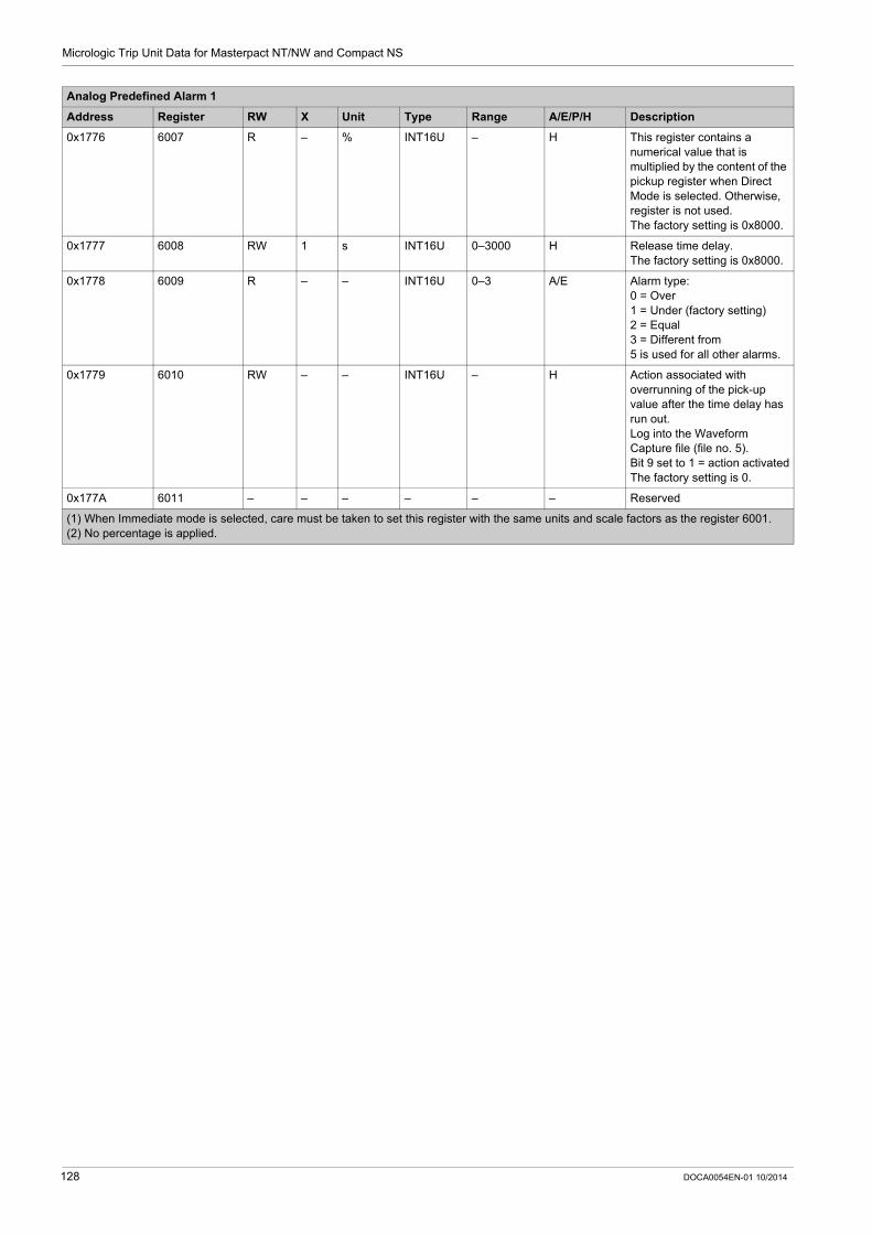
Micrologic Trip Unit Data for Masterpact NT/NW and Compact NS
0x1776 6007 R – % INT16U – H This register contains a numerical value that is multiplied by the content of the pickup register when Direct Mode is selected. Otherwise, register is not used.The factory setting is 0x8000.
0x1777 6008 RW 1 s INT16U 0–3000 H Release time delay.The factory setting is 0x8000.
0x1778 6009 R – – INT16U 0–3 A/E Alarm type:0 = Over1 = Under (factory setting)2 = Equal3 = Different from5 is used for all other alarms.
0x1779 6010 RW – – INT16U – H Action associated with overrunning of the pick-up value after the time delay has run out.Log into the Waveform Capture file (file no. 5).Bit 9 set to 1 = action activatedThe factory setting is 0.
0x177A 6011 – – – – – – Reserved
Analog Predefined Alarm 1
Address Register RW X Unit Type Range A/E/P/H Description
(1) When Immediate mode is selected, care must be taken to set this register with the same units and scale factors as the register 6001.(2) No percentage is applied.
128 DOCA0054EN-01 10/2014

Micrologic Trip Unit Data for Masterpact NT/NW and Compact NS
Basic Protection Parameters
Neutral Protection Parameters
The neutral protection is only available when system type in register 3314 is 30 or 41 (see page 151).
Long-Time Protection Parameters
Address Register RW X Unit Type Range A/E/P/H Description
0x2230 8753 RW 1 – INT16U 0–3 A/E/P/H Type of neutral protection: (1)0 = OFF1 = N/2 (Ir/2)2 = N (Ir)3 = Nx1.6 (1.6 Ir) (2)
(1) Write Access only with Micrologic P and H trip unit.(2) Value accessible only for Micrologic P and H trip unit.
Address Register RW X Unit Type Range A/E/P/H Bit Description
0x2231 8754 R – – INT16U 0–1 A/E/P/H – Status: 0x0001 = On
0x2232 8755 RW – – INT16U – – – Type of IDMTL curve (1)
A/E/P/H 0 Standard long-time curve I2t (factory setting)
P/H 1 SIT curve
P/H 2 VIT curve
P/H 3 EIT (I2t on) curve
P/H 4 HVF curve
P/H 5 Constant time (I2t off)
– 6–15 Reserved
0x2233–0x2234
8756–8757
RW 1 A MOD 10000
40– 8000 A/E/P/H – Ir pick-up value (1)
0x2235 8758 RW 1 ms INT16U 500– 24000
A/E/P/H – tr time delay (1)
0x2236–0x2238
8759–8761
– – – – – – – Reserved
0x2239 8762 RW – – INT16U – H – Waveform capture setting:0 = no waveform capture0x0100 = waveform capture into the Fault Waveform Capture file no. 22 at the end of the time delay tr.
0x223A 8763 RW – – INT16U – – – M2C/M6C programmable contact setting:Bit set to 1 = contact closed at the end of the time delay tr (factory setting)Bit set to 0 = contact open at the end of the time delay tr
– 0 Always set to 1
– 1–7 Reserved
E/P/H 8 Contact 1
E/P/H 9 Contact 2
P/H 10 Contact 3
P/H 11 Contact 4
P/H 12 Contact 5
P/H 13 Contact 6
– 14–15 Reserved
(1) Write Access only with Micrologic P and H trip unit.
DOCA0054EN-01 10/2014 129

Micrologic Trip Unit Data for Masterpact NT/NW and Compact NS
Short-Time Protection Parameters
Instantaneous Protection Parameters
Address Register RW X Unit Type Range A/E/P/H Bit Description
0x223B 8764 R – – INT16U 0–1 A/E/P/H – Status: 0x0001 = On
0x223C 8765 RW – – INT16U 0–1 A/E/P/H – Type of protection: (1)
0 = I2t On
1 = I2t Off
0x223D–0x223E
8766–8767
RW 1 A MOD 10000
60– 80 000
A/E/P/H – Isd pick-up value (1)
0x223F 8768 RW 1 ms INT16U 0–400 A/E/P/H – tsd time delay (1)0 s: valid only for the I²t off position100–400 ms: valid for the I²t on and I²t off positions
0x2243 8772 RW – – INT16U – H – Waveform capture setting:0 = no waveform capture0x0100 = waveform capture into the Fault Waveform Capture file at the end of the time delay tsd.
0x2244 8773 RW – – INT16U – – – M2C/M6C programmable contact setting:Bit set to 1 = contact closed at the end of the time delay tsd (factory setting)Bit set to 0 = contact open at the end of the time delay tsd
– 0 Always set to 1
– 1–7 Reserved
E/P/H 8 Contact 1
E/P/H 9 Contact 2
P/H 10 Contact 3
P/H 11 Contact 4
P/H 12 Contact 5
P/H 13 Contact 6
– 14–15 Reserved
(1) Write Access only with Micrologic P and H trip unit.
Address Register RW X Unit Type Range A/E/P/H Bit Description
0x2245 8774 R – – INT16U 0x0001–0x0101
A/E/P/H – 0x0001 = protection active (factory setting)0x0101 = protection OFF
0x2246 8775 – – – – – – – Reserved
0x2247–0x2248
8776–8777
RW 1 A MOD 10000
200–120000
A/E/P/H – I pick-up value for the instantaneous protection (1)
0x2249 8778 – – – – – – – Reserved
0x224D 8782 RW – – INT16U – H – Waveform capture setting:0 = no waveform capture0x0100 = waveform capture into the Fault Waveform Capture file at the end of the time delay.
(1) Write Access only with Micrologic P and H trip unit.
130 DOCA0054EN-01 10/2014

Micrologic Trip Unit Data for Masterpact NT/NW and Compact NS
Ground-Fault Protection Parameters
0x224E 8783 RW – – INT16U – – – M2C/M6C programmable contact setting:Bit set to 1 = contact closed at the end of the time delay (factory setting)Bit set to 0 = contact open at the end of the time delay
– 0 Always set to 1
– 1–7 Reserved
E/P/H 8 Contact 1
E/P/H 9 Contact 2
P/H 10 Contact 3
P/H 11 Contact 4
P/H 12 Contact 5
P/H 13 Contact 6
– 14–15 Reserved
Address Register RW X Unit Type Range A/E/P/H Bit Description
(1) Write Access only with Micrologic P and H trip unit.
Address Register RW X Unit Type Range A/E/P/H Bit Description
0x224F 8784 RW – – INT16U 0x0001–0x0101
A/E/P/H – Protection status: (1) (2)0x0001 = protection active (factory setting)0x0101 = protection OFF
0x2250 8785 RW – – INT16U 0–1 A/E/P/H – Type of protection: (1)
0 = I2t On
1 = I2t Off
0x2251–0x2252
8786–8787
RW 1 A MOD 10000
30–1200
A/E/P/H – Ig pickup for the ground-fault protection (1)
0x2253 8788 RW 1 ms INT16U 0–400 A/E/P/H – tg tripping time delay for the ground-fault protection: (1)
0 s = valid only for the I2t off position100 to 400 ms = valid for the
I2t on and I2t off positions
0x2257 8792 RW – – INT16U – H – Waveform capture setting:0 = no waveform capture0x0100 = waveform capture into the Fault Waveform Capture file at the end of the time delay tg.
(1) Write Access only with Micrologic P and H trip unit.(2) In order to be able to write this register, the following conditions must be met: Micrologic 6 P or 6 H firmware version 8.244 or above (see register 8710) Activation of the option Ground-Fault Inhibit through the utility enable_GFI (available on request)
DOCA0054EN-01 10/2014 131

Micrologic Trip Unit Data for Masterpact NT/NW and Compact NS
Earth-Leakage (Vigi) Protection Parameters
0x2258 8793 RW – – INT16U – – – M2C/M6C programmable contact setting:Bit set to 1 = contact closed at the end of the time delay tg (factory setting)Bit set to 0 = contact open at the end of the time delay tg
– 0 Always set to 1
– 1–7 Reserved
E/P/H 8 Contact 1
E/P/H 9 Contact 2
P/H 10 Contact 3
P/H 11 Contact 4
P/H 12 Contact 5
P/H 13 Contact 6
– 14–15 Reserved
Address Register RW X Unit Type Range A/E/P/H Bit Description
(1) Write Access only with Micrologic P and H trip unit.(2) In order to be able to write this register, the following conditions must be met: Micrologic 6 P or 6 H firmware version 8.244 or above (see register 8710) Activation of the option Ground-Fault Inhibit through the utility enable_GFI (available on request)
Address Register RW X Unit Type Range A/E/P/H Bit Description
0x2259 8794 R – – INT16U 0x0001 A/P/H – 0x0001 = protection active
0x225A 8795 – – – – – – – Reserved
0x225B–0x225C
8796–8797
RW 1 mA MOD 10000
5–300 A/P/H – In pickup for the earth-leakage protection (1)
0x225D 8798 RW 1 ms INT16U 0–1000 A/P/H – t tripping time delay for the earth-leakage protection (1)
0x2261 8802 RW – – INT16U – H – Waveform capture setting:0 = no waveform capture0x0100 = waveform capture into the Fault Waveform Capture file at the end of the time delay t.
0x2262 8803 RW – – INT16U – P/H – M2C/M6C programmable contact setting:Bit set to 1 = contact closed at the end of the time delay t (factory setting)Bit set to 0 = contact open at the end of the time delay t
– 0 Always set to 1
– 1–7 Reserved
P/H 8 Contact 1
P/H 9 Contact 2
P/H 10 Contact 3
P/H 11 Contact 4
P/H 12 Contact 5
P/H 13 Contact 6
– 14–15 Reserved
(1) Write Access only with Micrologic P and H trip unit.
132 DOCA0054EN-01 10/2014

Micrologic Trip Unit Data for Masterpact NT/NW and Compact NS
Advanced Protection Parameters
Ground-Fault Alarm
Earth-Leakage Alarm
Address Register RW X Unit Type Range A/E/P/H Bit Description
0x259C 9629 RW – – INT16U 0x0001–0x0101
P/H – 0x0001 = alarm active0x0101 = OFF (factory setting)
0x259D 9630 – – – – – – – Reserved
0x259E–0x259F
9631–9632
RW 1 A MOD 10000
20–1200 P/H – Alarm pick-up value (1)Minimum value = 0.05 x InFactory setting = 1200 A
0x25A0 9633 RW 10 s INT16U 10–100 P/H – Alarm pick-up time delayFactory setting = 100 (10 s)
0x25A1–0x25A2
9634–9635
RW 1 A MOD 10000
20–1200 P/H – Alarm drop-out value (1)Maximum value = alarm pick-up valueMinimum value = 0.05 x InFactory setting = 1200 A
0x25A3 9636 RW 10 s INT16U 10–100 P/H – Alarm drop-out time delay (1)Factory setting = 10 (1 s)
0x25A4 9637 RW – – INT16U – H – Waveform capture setting:0 = no waveform capture0x0100 = waveform capture into the Fault Waveform Capture file at the end of the time delay.
0x25A5 9638 RW – – INT16U – – – M2C/M6C programmable contact setting:Bit set to 1 = contact closed at the end of the time delayBit set to 0 = contact open at the end of the time delay (factory setting)
– 0 Always set to 0 (trip disabled for this type of alarm)
– 1–7 Reserved
P/H 8 Contact 1
P/H 9 Contact 2
P/H 10 Contact 3
P/H 11 Contact 4
P/H 12 Contact 5
P/H 13 Contact 6
– 14–15 Reserved
(1) Accessible only with Micrologic, 5.0 P, 6.0 P, 5.0 H, and 6.0 H trip unit.
Address Register RW X Unit Type Range A/E/P/H Bit Description
0x25A6 9639 RW – – INT16U 0x0001–0x0101
P/H – Alarm status: (1)0x0001 = alarm active0x0101 = OFF (factory setting)
(1) Accessible only with Micrologic 7.0 P and 7.0 H trip unit.
DOCA0054EN-01 10/2014 133
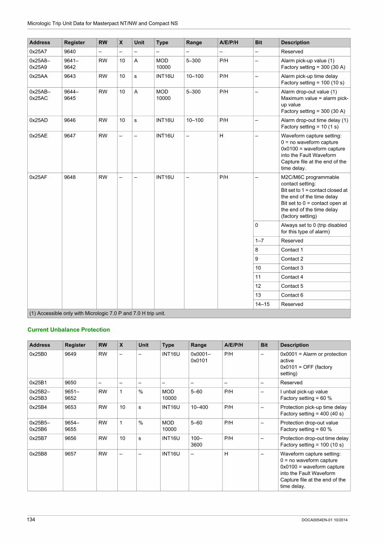
Micrologic Trip Unit Data for Masterpact NT/NW and Compact NS
Current Unbalance Protection
0x25A7 9640 – – – – – – – Reserved
0x25A8–0x25A9
9641–9642
RW 10 A MOD10000
5–300 P/H – Alarm pick-up value (1)Factory setting = 300 (30 A)
0x25AA 9643 RW 10 s INT16U 10–100 P/H – Alarm pick-up time delayFactory setting = 100 (10 s)
0x25AB–0x25AC
9644–9645
RW 10 A MOD 10000
5–300 P/H – Alarm drop-out value (1)Maximum value = alarm pick-up valueFactory setting = 300 (30 A)
0x25AD 9646 RW 10 s INT16U 10–100 P/H – Alarm drop-out time delay (1)Factory setting = 10 (1 s)
0x25AE 9647 RW – – INT16U – H – Waveform capture setting:0 = no waveform capture0x0100 = waveform capture into the Fault Waveform Capture file at the end of the time delay.
0x25AF 9648 RW – – INT16U – P/H – M2C/M6C programmable contact setting:Bit set to 1 = contact closed at the end of the time delayBit set to 0 = contact open at the end of the time delay (factory setting)
0 Always set to 0 (trip disabled for this type of alarm)
1–7 Reserved
8 Contact 1
9 Contact 2
10 Contact 3
11 Contact 4
12 Contact 5
13 Contact 6
14–15 Reserved
Address Register RW X Unit Type Range A/E/P/H Bit Description
(1) Accessible only with Micrologic 7.0 P and 7.0 H trip unit.
Address Register RW X Unit Type Range A/E/P/H Bit Description
0x25B0 9649 RW – – INT16U 0x0001–0x0101
P/H – 0x0001 = Alarm or protection active0x0101 = OFF (factory setting)
0x25B1 9650 – – – – – – – Reserved
0x25B2–0x25B3
9651–9652
RW 1 % MOD 10000
5–60 P/H – I unbal pick-up valueFactory setting = 60 %
0x25B4 9653 RW 10 s INT16U 10–400 P/H – Protection pick-up time delayFactory setting = 400 (40 s)
0x25B5–0x25B6
9654–9655
RW 1 % MOD 10000
5–60 P/H – Protection drop-out valueFactory setting = 60 %
0x25B7 9656 RW 10 s INT16U 100–3600
P/H – Protection drop-out time delayFactory setting = 100 (10 s)
0x25B8 9657 RW – – INT16U – H – Waveform capture setting:0 = no waveform capture0x0100 = waveform capture into the Fault Waveform Capture file at the end of the time delay.
134 DOCA0054EN-01 10/2014
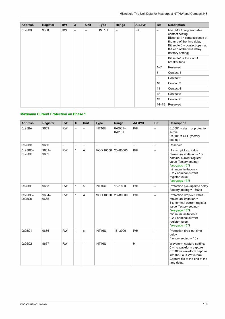
Micrologic Trip Unit Data for Masterpact NT/NW and Compact NS
Maximum Current Protection on Phase 1
0x25B9 9658 RW – – INT16U – P/H – M2C/M6C programmable contact setting:Bit set to 1 = contact closed at the end of the time delayBit set to 0 = contact open at the end of the time delay (factory setting)
0 Bit set to1 = the circuit breaker trips
1–7 Reserved
8 Contact 1
9 Contact 2
10 Contact 3
11 Contact 4
12 Contact 5
13 Contact 6
14–15 Reserved
Address Register RW X Unit Type Range A/E/P/H Bit Description
Address Register RW X Unit Type Range A/E/P/H Bit Description
0x25BA 9659 RW – – INT16U 0x0001–0x0101
P/H – 0x0001 = alarm or protection active0x0101 = OFF (factory setting)
0x25BB 9660 – – – – – – – Reserved
0x25BC–0x25BD
9661–9662
RW 1 A MOD 10000 20–80000 P/H – I1 max. pick-up valuemaximum limitation = 1 x nominal current register value (factory setting) (see page 157)minimum limitation = 0.2 x nominal current register value (see page 157)
0x25BE 9663 RW 1 s INT16U 15–1500 P/H – Protection pick-up time delayFactory setting = 1500 s
0x25BF–0x25C0
9664–9665
RW 1 A MOD 10000 20–80000 P/H – Protection drop-out valuemaximum limitation = 1 x nominal current register value (factory setting) (see page 157)minimum limitation = 0.2 x nominal current register value (see page 157)
0x25C1 9666 RW 1 s INT16U 15–3000 P/H – Protection drop-out time delayFactory setting = 15 s
0x25C2 9667 RW – – INT16U – H – Waveform capture setting:0 = no waveform capture0x0100 = waveform capture into the Fault Waveform Capture file at the end of the time delay.
DOCA0054EN-01 10/2014 135

Micrologic Trip Unit Data for Masterpact NT/NW and Compact NS
Maximum Current Protection on Phase 2
0x25C3 9668 RW – – INT16U – P/H – M2C/M6C programmable contact setting:Bit set to 1 = contact closed at the end of the time delayBit set to 0 = contact open at the end of the time delay (factory setting)
0 Bit set to1 = the circuit breaker trips
1–7 Reserved
8 Contact 1
9 Contact 2
10 Contact 3
11 Contact 4
12 Contact 5
13 Contact 6
14–15 Reserved
Address Register RW X Unit Type Range A/E/P/H Bit Description
Address Register RW X Unit Type Range A/E/P/H Bit Description
0x25C4 9669 RW – – INT16U 0x0001–0x0101
P/H – 0x0001 = alarm or protection active0x0101 = OFF (factory setting)
0x25C5 9670 – – – – – – – Reserved
0x25C6–0x25C7
9671–9672
RW 1 A MOD 10000
20–80000 P/H – I2 max. pick-up valuemaximum limitation = 1 x nominal current register value (factory setting) (see page 157)minimum limitation = 0.2 x nominal current register value (see page 157)
0x25C8 9673 RW 1 s INT16U 15–1500 P/H – Protection pick-up time delayFactory setting = 1500 s
0x25C9–0x25CA
9674–9675
RW 1 A MOD 10000
20–80000 P/H – Protection drop-out valuemaximum limitation = 1 x nominal current register value (factory setting) (see page 157)minimum limitation = 0.2 x nominal current register value (see page 157)
0x25CB 9676 RW 1 s INT16U 15–3000 P/H – Protection drop-out time delayFactory setting = 15 s
0x25CC 9677 RW – – INT16U – H – Waveform capture setting:0 = no waveform capture0x0100 = waveform capture into the Fault Waveform Capture file at the end of the time delay.
136 DOCA0054EN-01 10/2014

Micrologic Trip Unit Data for Masterpact NT/NW and Compact NS
Maximum Current Protection on Phase 3
0x25CD 9678 RW – – INT16U – P/H – M2C/M6C programmable contact setting:Bit set to 1 = contact closed at the end of the time delayBit set to 0 = contact open at the end of the time delay (factory setting)
0 Bit set to1 = the circuit breaker trips
1–7 Reserved
8 Contact 1
9 Contact 2
10 Contact 3
11 Contact 4
12 Contact 5
13 Contact 6
14–15 Reserved
Address Register RW X Unit Type Range A/E/P/H Bit Description
Address Register RW X Unit Type Range A/E/P/H Bit Description
0x25CE 9679 RW – – INT16U 0x0001–0x0101
P/H – 0x0001 = alarm or protection active0x0101 = OFF (factory setting)
0x25CF 9680 – – – – – – – Reserved
0x25D0–0x25D1
9681–9682
RW 1 A MOD 10000
20–80000 P/H – I3 max. pick-up valuemaximum limitation = 1 x nominal current register value (factory setting) (see page 157)minimum limitation = 0.2 x nominal current register value (see page 157)
0x25D2 9683 RW 1 s INT16U 15–1500 P/H – Protection pick-up time delayFactory setting = 1500 s
0x25D3–0x25D4
9684–9685
RW 1 A MOD 10000
20–80000 P/H – Protection drop-out valuemaximum limitation = 1 x nominal current register value (factory setting) (see page 157)minimum limitation = 0.2 x nominal current register value (see page 157)
0x25D5 9686 RW 1 s INT16U 15–3000 P/H – Protection drop-out time delayFactory setting = 15 s
0x25D6 9687 RW – – INT16U – H – Waveform capture setting:0 = no waveform capture0x0100 = waveform capture into the Fault Waveform Capture file at the end of the time delay.
DOCA0054EN-01 10/2014 137
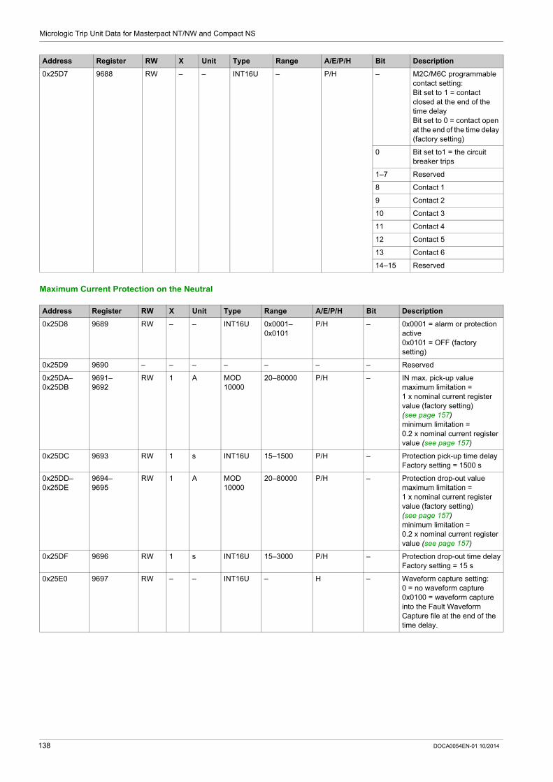
Micrologic Trip Unit Data for Masterpact NT/NW and Compact NS
Maximum Current Protection on the Neutral
0x25D7 9688 RW – – INT16U – P/H – M2C/M6C programmable contact setting:Bit set to 1 = contact closed at the end of the time delayBit set to 0 = contact open at the end of the time delay (factory setting)
0 Bit set to1 = the circuit breaker trips
1–7 Reserved
8 Contact 1
9 Contact 2
10 Contact 3
11 Contact 4
12 Contact 5
13 Contact 6
14–15 Reserved
Address Register RW X Unit Type Range A/E/P/H Bit Description
Address Register RW X Unit Type Range A/E/P/H Bit Description
0x25D8 9689 RW – – INT16U 0x0001–0x0101
P/H – 0x0001 = alarm or protection active0x0101 = OFF (factory setting)
0x25D9 9690 – – – – – – – Reserved
0x25DA–0x25DB
9691–9692
RW 1 A MOD 10000
20–80000 P/H – IN max. pick-up valuemaximum limitation = 1 x nominal current register value (factory setting) (see page 157)minimum limitation = 0.2 x nominal current register value (see page 157)
0x25DC 9693 RW 1 s INT16U 15–1500 P/H – Protection pick-up time delayFactory setting = 1500 s
0x25DD–0x25DE
9694–9695
RW 1 A MOD 10000
20–80000 P/H – Protection drop-out valuemaximum limitation = 1 x nominal current register value (factory setting) (see page 157)minimum limitation = 0.2 x nominal current register value (see page 157)
0x25DF 9696 RW 1 s INT16U 15–3000 P/H – Protection drop-out time delayFactory setting = 15 s
0x25E0 9697 RW – – INT16U – H – Waveform capture setting:0 = no waveform capture0x0100 = waveform capture into the Fault Waveform Capture file at the end of the time delay.
138 DOCA0054EN-01 10/2014

Micrologic Trip Unit Data for Masterpact NT/NW and Compact NS
Minimum Voltage Protection
0x25E1 9698 RW – – INT16U – P/H – M2C/M6C programmable contact setting:Bit set to 1 = contact closed at the end of the time delayBit set to 0 = contact open at the end of the time delay (factory setting)
0 Bit set to1 = the circuit breaker trips
1–7 Reserved
8 Contact 1
9 Contact 2
10 Contact 3
11 Contact 4
12 Contact 5
13 Contact 6
14–15 Reserved
Address Register RW X Unit Type Range A/E/P/H Bit Description
Address Register RW X Unit Type Range A/E/P/H Bit Description
0x25E2 9699 RW – – INT16U 0x0001–0x0101
P/H – 0x0001 = alarm or protection active0x0101 = OFF (factory setting)
0x25E3 9700 – – – – – – – Reserved
0x25E4–0x25E5
9701–9702
RW 1 V MOD 10000
100–1200 P/H – U min. pick-up valueMaximum value = protection pick-up value of maximum voltage.Factory setting = 100 V
0x25E6 9703 RW 100 s INT16U 20–500 P/H – Protection pick-up time delayFactory setting = 500 (5 s)
0x25E7–0x25E8
9704–9705
RW 1 V MOD 10000
100–1200 P/H – Protection drop-out valueMinimum value = protection pick-up valueFactory setting = 100 V
0x25E9 9706 RW 100 s INT16U 120–3600 P/H – Protection drop-out time delayFactory setting = 120 (1.2 s)
0x25EA 9707 RW – – INT16U – H – Waveform capture setting:0 = no waveform capture0x0100 = waveform capture into the Fault Waveform Capture file at the end of the time delay.
DOCA0054EN-01 10/2014 139

Micrologic Trip Unit Data for Masterpact NT/NW and Compact NS
Maximum Voltage Protection
0x25EB 9708 RW – – INT16U – P/H – M2C/M6C programmable contact setting:Bit set to 1 = contact closed at the end of the time delayBit set to 0 = contact open at the end of the time delay (factory setting)
0 Bit set to1 = the circuit breaker trips
1–7 Reserved
8 Contact 1
9 Contact 2
10 Contact 3
11 Contact 4
12 Contact 5
13 Contact 6
14–15 Reserved
Address Register RW X Unit Type Range A/E/P/H Bit Description
Address Register RW X Unit Type Range A/E/P/H Bit Description
0x25EC 9709 RW – – INT16U 0x0001–0x0101
P/H – 0x0001 = alarm or protection active0x0101 = OFF (factory setting)
0x25ED 9710 – – – – – – – Reserved
0x25EE–0x25EF
9711–9712
RW 1 V MOD 10000
100–1200 P/H – U max. pick-up valueMinimum value = protection pick-up value of minimum voltage.Factory setting = +5 % above primary voltage on the voltage transformer (see page 153)
0x25F0 9713 RW 100 s INT16U 20–500 P/H – Protection pick-up time delayFactory setting = 500 (5 s)
0x25F1–0x25F2
9714–9715
RW 1 V MOD 10000
100–1200 P/H – Protection drop-out valueMaximum value = protection pick-up valueFactory setting = +5 % primary voltage on the voltage transformer (see page 153)
0x25F3 9716 RW 100 s INT16U 120–3600 P/H – Protection drop-out time delayFactory setting = 120 (1.2 s)
140 DOCA0054EN-01 10/2014

Micrologic Trip Unit Data for Masterpact NT/NW and Compact NS
Voltage Unbalance Protection
0x25F4 9717 RW – – INT16U – H – Waveform capture setting:0 = no waveform capture0x0100 = waveform capture into the Fault Waveform Capture file at the end of the time delay.
0x25F5 9718 RW – – INT16U – P/H – M2C/M6C programmable contact setting:Bit set to 1 = contact closed at the end of the time delayBit set to 0 = contact open at the end of the time delay (factory setting)
0 Bit set to1 = the circuit breaker trips
1–7 Reserved
8 Contact 1
9 Contact 2
10 Contact 3
11 Contact 4
12 Contact 5
13 Contact 6
14–15 Reserved
Address Register RW X Unit Type Range A/E/P/H Bit Description
Address Register RW X Unit Type Range A/E/P/H Bit Description
0x25F6 9719 RW – – INT16U 0x0001–0x0101
P/H – 0x0001 = alarm or protection active0x0101 = OFF (factory setting)
0x25F7 9720 – – – – – – – Reserved
0x25F8–0x25F9
9721–9722
RW 1 % MOD 10000 2–30 P/H – U unbal pick-up valueFactory setting = 30 %
0x25FA 9723 RW 10 s INT16U 10–400 P/H – Protection pick-up time delayFactory setting = 400 (40 s)
0x25FB–0x25FC
9724–9725
RW 1 % MOD 10000 2–30 P/H – Protection drop-out valueMaximum value = protection pick-up valueFactory setting = 30 %
0x25FD 9726 RW 10 s INT16U 100–3600 P/H – Protection drop-out time delayFactory setting = 100 (10 s)
DOCA0054EN-01 10/2014 141

Micrologic Trip Unit Data for Masterpact NT/NW and Compact NS
Reverse Power Protection
0x25FE 9727 RW – – INT16U – H – Waveform capture setting:0 = no waveform capture0x0100 = waveform capture into the Fault Waveform Capture file at the end of the time delay.
0x25FF 9728 RW – – INT16U – – – M2C/M6C programmable contact setting:Bit set to 1 = contact closed at the end of the time delayBit set to 0 = contact open at the end of the time delay (factory setting)
0 Bit set to1 = the circuit breaker trips
1–7 Reserved
8 Contact 1
9 Contact 2
10 Contact 3
11 Contact 4
12 Contact 5
13 Contact 6
14–15 Reserved
Address Register RW X Unit Type Range A/E/P/H Bit Description
Address Register RW X Unit Type Range A/E/P/H Bit Description
0x260A 9739 RW – – INT16U 0x0001–0x0101
P/H – 0x0001 = alarm or protection active0x0101 = OFF (factory setting)
0x260B 9740 RW – – INT16U – P/H – Direction of active power flowBit 0 set to 0 = standard - power connections made to the lower terminals of the circuit breakerBit 0 set to 1 = reverse - power connections made to the upper terminals of the circuit breakerThe direction may be modified by the trip unit or by directly writing to the register after obtaining the right (using a command).Factory setting = 0x0000
0x260C–0x260D
9741–9742
RW 1 kW MOD 10000
5–500 P/H – rP max. pick-up valueFactory setting = 500 kW
0x260E 9743 RW 10 s INT16U 2–200 P/H – Protection pick-up time delayFactory setting = 200 (20 s)
142 DOCA0054EN-01 10/2014

Micrologic Trip Unit Data for Masterpact NT/NW and Compact NS
Minimum Frequency Protection
0x260F–0x2610
9744–9745
RW 1 kW MOD 10000
5–500 P/H – Protection drop-out valueMaximum value = protection pick-up valueFactory setting = 500 kW
0x2611 9746 RW 10 s INT16U 10–3600 P/H – Protection drop-out time delayFactory setting = 10 (1 s)
0x2612 9747 RW – – INT16U – H – Waveform capture setting:0 = no waveform capture0x0100 = waveform capture into the Fault Waveform Capture file at the end of the time delay.
0x2613 9748 RW – – INT16U – P/H – M2C/M6C programmable contact setting:Bit set to 1 = contact closed at the end of the time delayBit set to 0 = contact open at the end of the time delay (factory setting)
0 Bit set to1 = the circuit breaker trips
1–7 Reserved
8 Contact 1
9 Contact 2
10 Contact 3
11 Contact 4
12 Contact 5
13 Contact 6
14–15 Reserved
Address Register RW X Unit Type Range A/E/P/H Bit Description
Address Register RW X Unit Type Range A/E/P/H Bit Description
0x2614 9749 RW – – INT16U 0x0001–0x0101
P/H – 0x0001 = alarm or protection active0x0101 = OFF (factory setting)
0x2615 9750 – – – – – – – Reserved
0x2616–0x2617
9751–9752
RW 10 Hz MOD 10000
450–5400 P/H – F min. pick-up valueMaximum value = protection pick-up value of maximum frequencyFactory setting = 450 (45 Hz)
0x2618 9753 RW 100 s INT16U 20–500 P/H – Protection pick-up time delayFactory setting = 500 (5 s)
0x2619–0x261A
9754–9755
RW 10 Hz MOD 10000
450–4400 P/H – Protection drop-out valueMinimum value = protection pick-up valueFactory setting = 450 (45 Hz)
DOCA0054EN-01 10/2014 143

Micrologic Trip Unit Data for Masterpact NT/NW and Compact NS
Maximum Frequency Protection
0x261B 9756 RW 100 s INT16U 100–3600 P/H – Protection drop-out time delayFactory setting = 100 (1 s)
0x261C 9757 RW – – INT16U – H – Waveform capture setting:0 = no waveform capture0x0100 = waveform capture into the Fault Waveform Capture file at the end of the time delay.
0x261D 9758 RW – – INT16U – P/H – M2C/M6C programmable contact setting:Bit set to 1 = contact closed at the end of the time delayBit set to 0 = contact open at the end of the time delay (factory setting)
0 Bit set to1 = the circuit breaker trips
1–7 Reserved
8 Contact 1
9 Contact 2
10 Contact 3
11 Contact 4
12 Contact 5
13 Contact 6
14–15 Reserved
Address Register RW X Unit Type Range A/E/P/H Bit Description
Address Register RW X Unit Type Range A/E/P/H Bit Description
0x261E 9759 RW – – INT16U 0x0001–0x0101
P/H – 0x0001 = alarm or protection active0x0101 = OFF (factory setting)
0x261F 9760 – – – – – – – Reserved
0x2620–0x2621
9761–9762
RW 10 Hz MOD 10000
450–5400 P/H – F max. pick-up valueMinimum value = protection pick-up value of minimum frequencyFactory setting = 650 (65 Hz)
0x2622 9763 RW 100 s INT16U 20–500 P/H – Protection pick-up time delayFactory setting = 500 (5 s)
0x2623–0x2624
9764–9765
RW 10 Hz MOD 10000
450–4400 P/H – Protection drop-out valueMaximum value = protection pick-up valueFactory setting = 650 (65 Hz)
0x2625 9766 RW 100 s INT16U 100–3600 P/H – Protection drop-out time delayFactory setting = 100 (1 s)
144 DOCA0054EN-01 10/2014
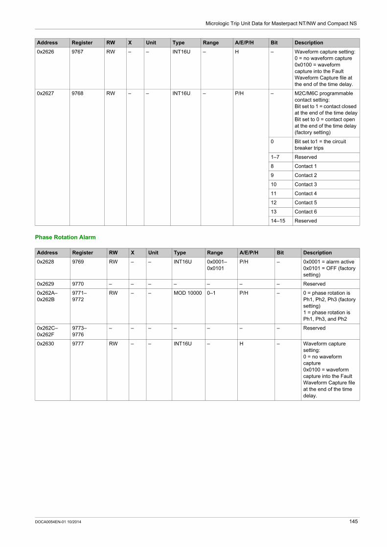
Micrologic Trip Unit Data for Masterpact NT/NW and Compact NS
Phase Rotation Alarm
0x2626 9767 RW – – INT16U – H – Waveform capture setting:0 = no waveform capture0x0100 = waveform capture into the Fault Waveform Capture file at the end of the time delay.
0x2627 9768 RW – – INT16U – P/H – M2C/M6C programmable contact setting:Bit set to 1 = contact closed at the end of the time delayBit set to 0 = contact open at the end of the time delay (factory setting)
0 Bit set to1 = the circuit breaker trips
1–7 Reserved
8 Contact 1
9 Contact 2
10 Contact 3
11 Contact 4
12 Contact 5
13 Contact 6
14–15 Reserved
Address Register RW X Unit Type Range A/E/P/H Bit Description
Address Register RW X Unit Type Range A/E/P/H Bit Description
0x2628 9769 RW – – INT16U 0x0001–0x0101
P/H – 0x0001 = alarm active0x0101 = OFF (factory setting)
0x2629 9770 – – – – – – – Reserved
0x262A–0x262B
9771–9772
RW – – MOD 10000 0–1 P/H – 0 = phase rotation is Ph1, Ph2, Ph3 (factory setting)1 = phase rotation is Ph1, Ph3, and Ph2
0x262C–0x262F
9773–9776
– – – – – – – Reserved
0x2630 9777 RW – – INT16U – H – Waveform capture setting:0 = no waveform capture0x0100 = waveform capture into the Fault Waveform Capture file at the end of the time delay.
DOCA0054EN-01 10/2014 145

Micrologic Trip Unit Data for Masterpact NT/NW and Compact NS
Load Shedding and Reconnection Based on Current
0x2631 9778 RW – – INT16U – P/H – M2C/M6C programmable contact setting:Bit set to 1 = contact closed at the end of the time delayBit set to 0 = contact open at the end of the time delay (factory setting)
0 Always set to 0 (trip disabled for this type of alarm)
1–7 Reserved
8 Contact 1
9 Contact 2
10 Contact 3
11 Contact 4
12 Contact 5
13 Contact 6
14–15 Reserved
Address Register RW X Unit Type Range A/E/P/H Bit Description
Address Register RW X Unit Type Range A/E/P/H Bit Description
0x2632 9779 RW – – INT16U 0x0001–0x0101
P/H – 0x0001 = alarm active0x0101 = OFF (factory setting)
0x2633 9780 – – – – – – – Reserved
0x2634–0x2635
9781–9782
RW 1 % MOD 10000
50–100 P/H – Pick-up for load shedding and reconnection based on current, expressed as a % of the long-time Ir pick-up valueFactory setting = 100 %
0x2636 9783 RW 1 %Tr INT16U 20–80 P/H – Pick-up time delay for load shedding and reconnection based on current, expressed as a % of the longtime delay tr pick-up value (20–80 %)Factory setting = 80 %
0x2637–0x2638
9784–9785
RW 1 % MOD 10000
30–100 P/H – Drop-out for load shedding and reconnection based on current, expressed as a % of the longtime Ir pick-up valueFactory setting = 100 %
0x2639 9786 RW 1 s INT16U 10–600 P/H Drop-out time delay for load shedding and reconnection based on currentFactory setting = 10 s
0x263A 9787 RW – – INT16U – H – Waveform capture setting:0 = no waveform capture0x0100 = waveform capture into the Fault Waveform Capture file at the end of the time delay.
146 DOCA0054EN-01 10/2014

Micrologic Trip Unit Data for Masterpact NT/NW and Compact NS
Load Shedding and Reconnection Based on Power
0x263B 9788 RW – – INT16U – – – M2C/M6C programmable contact setting:Bit set to 1 = contact closed at the end of the time delayBit set to 0 = contact open at the end of the time delay (factory setting)
P/H 0 Always set to 0 (trip disabled for this type of alarm)
– 1–7 Reserved
P/H 8 Contact 1
P/H 9 Contact 2
P/H 10 Contact 3
P/H 11 Contact 4
P/H 12 Contact 5
P/H 13 Contact 6
– 14–15 Reserved
Address Register RW X Unit Type Range A/E/P/H Bit Description
Address Register RW X Unit Type Range A/E/P/H Bit Description
0x263C 9789 RW – – INT16U 0x0001–0x0101
P/H – 0x0001 = alarm active0x0101 = OFF (factory setting)
0x263D 9790 RW – – INT16U – – – Direction of active power flowBit set to 0 = standard, power connections made to the lower terminals of the circuit breakerBit set to 1 = reverse, power connections made to the upper terminals of the circuit breakerThe direction may be modified by the command interface or by directly writing to the register after obtaining the right (using a command).Factory setting = 0x0000
0x263E–0x263F
9791–9792
RW 1 kW MOD 10000
200–10000 P/H – Pick-up for load shedding and reconnection based on powerFactory setting = 10000 kW
0x2640 9793 RW 1 s INT16U 10–3600 P/H – Pick-up time delay for load shedding and reconnection based on powerFactory setting = 3600 s
0x2641–0x2642
9794–9795
RW 1 kW MOD 10000
100–10000 P/H – Drop-out for load shedding and reconnection based on powerFactory setting = 10000 kW
0x2643 9796 RW 1 s INT16U 10–3600 P/H – Drop-out time delay for load shedding and reconnection based on powerFactory setting = 10 s
DOCA0054EN-01 10/2014 147

Micrologic Trip Unit Data for Masterpact NT/NW and Compact NS
0x2644 9797 RW – – INT16U – H – Waveform capture setting:0 = no waveform capture0x0100 = waveform capture into the Fault Waveform Capture file at the end of the time delay.
0x2645 9798 RW – – INT16U – P/H – M2C/M6C programmable contact setting:Bit set to 1 = contact closed at the end of the time delayBit set to 0 = contact open at the end of the time delay (factory setting)
0 Always set to 0 (trip disabled for this type of alarm)
1–7 Reserved
8 Contact 1
9 Contact 2
10 Contact 3
11 Contact 4
12 Contact 5
13 Contact 6
14–15 Reserved
Address Register RW X Unit Type Range A/E/P/H Bit Description
148 DOCA0054EN-01 10/2014
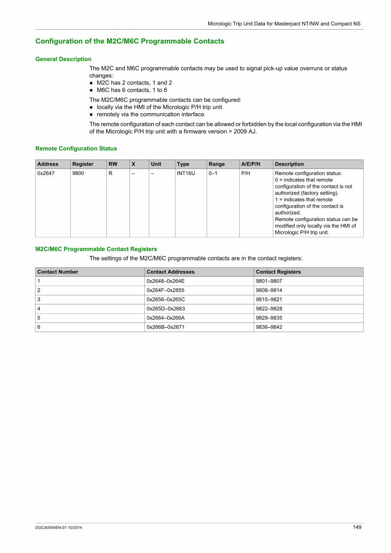
Micrologic Trip Unit Data for Masterpact NT/NW and Compact NS
Configuration of the M2C/M6C Programmable Contacts
General Description
The M2C and M6C programmable contacts may be used to signal pick-up value overruns or status changes: M2C has 2 contacts, 1 and 2 M6C has 6 contacts, 1 to 6
The M2C/M6C programmable contacts can be configured: locally via the HMI of the Micrologic P/H trip unit remotely via the communication interface
The remote configuration of each contact can be allowed or forbidden by the local configuration via the HMI of the Micrologic P/H trip unit with a firmware version > 2009 AJ.
Remote Configuration Status
M2C/M6C Programmable Contact Registers
The settings of the M2C/M6C programmable contacts are in the contact registers:
Address Register RW X Unit Type Range A/E/P/H Description
0x2647 9800 R – – INT16U 0–1 P/H Remote configuration status:0 = indicates that remote configuration of the contact is not authorized (factory setting).1 = indicates that remote configuration of the contact is authorized.Remote configuration status can be modified only locally via the HMI of Micrologic P/H trip unit.
Contact Number Contact Addresses Contact Registers
1 0x2648–0x264E 9801–9807
2 0x264F–0x2655 9808–9814
3 0x2656–0x265C 9815–9821
4 0x265D–0x2663 9822–9828
5 0x2664–0x266A 9829–9835
6 0x266B–0x2671 9836–9842
DOCA0054EN-01 10/2014 149
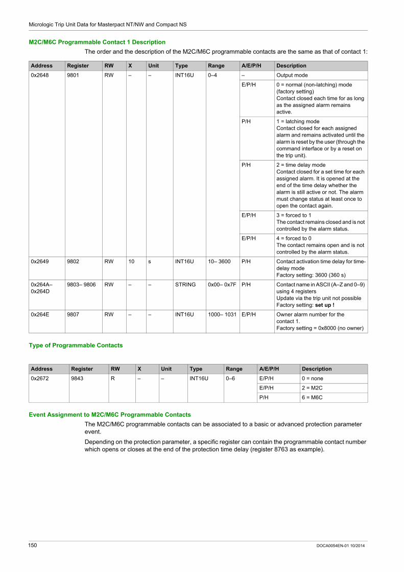
Micrologic Trip Unit Data for Masterpact NT/NW and Compact NS
M2C/M6C Programmable Contact 1 Description
The order and the description of the M2C/M6C programmable contacts are the same as that of contact 1:
Type of Programmable Contacts
Event Assignment to M2C/M6C Programmable Contacts
The M2C/M6C programmable contacts can be associated to a basic or advanced protection parameter event.
Depending on the protection parameter, a specific register can contain the programmable contact number which opens or closes at the end of the protection time delay (register 8763 as example).
Address Register RW X Unit Type Range A/E/P/H Description
0x2648 9801 RW – – INT16U 0–4 – Output mode
E/P/H 0 = normal (non-latching) mode (factory setting)Contact closed each time for as long as the assigned alarm remains active.
P/H 1 = latching modeContact closed for each assigned alarm and remains activated until the alarm is reset by the user (through the command interface or by a reset on the trip unit).
P/H 2 = time delay modeContact closed for a set time for each assigned alarm. It is opened at the end of the time delay whether the alarm is still active or not. The alarm must change status at least once to open the contact again.
E/P/H 3 = forced to 1The contact remains closed and is not controlled by the alarm status.
E/P/H 4 = forced to 0The contact remains open and is not controlled by the alarm status.
0x2649 9802 RW 10 s INT16U 10– 3600 P/H Contact activation time delay for time-delay modeFactory setting: 3600 (360 s)
0x264A–0x264D
9803– 9806 RW – – STRING 0x00– 0x7F P/H Contact name in ASCII (A–Z and 0–9) using 4 registersUpdate via the trip unit not possibleFactory setting: set up !
0x264E 9807 RW – – INT16U 1000– 1031 E/P/H Owner alarm number for the contact 1.Factory setting = 0x8000 (no owner)
Address Register RW X Unit Type Range A/E/P/H Description
0x2672 9843 R – – INT16U 0–6 E/P/H 0 = none
E/P/H 2 = M2C
P/H 6 = M6C
150 DOCA0054EN-01 10/2014

Micrologic Trip Unit Data for Masterpact NT/NW and Compact NS
Measurement Parameters
System Type
The setup ENVT (External Neutral Voltage Tap) presence command (command code = 46472) configures the content of the system type register.
Determining system type:
This table presents the text to choose on the Micrologic E trip unit display according to the system type determined previously:
Power Flow Sign
The power flow sign command (command code = 47240) configures the content of the power flow sign register.
Reactive Power Sign
Address Register RW X Unit Type Range A/E/P/H Description
0x0CF1 3314 RWC – – INT16U 30, 31, 40, 41
E/P/H System typeFactory setting: 40 with Micrologic E trip unit 41 with Micrologic P and H
trip units
If... Then... Result
the system type is 3-pole circuit breaker with external neutral current transformer and without external neutral voltage tap
system type = 30 Measurements of the phase-to-phase voltages are available. Measurements of the phase-to-neutral voltages are not available. Measurement of the neutral current is available. 3 wattmeters method is not possible.
the system type is 3-pole circuit breaker without external neutral current transformer and without external neutral voltage tap
system type = 31 Measurements of the phase-to-phase voltages are available. Measurements of the phase-to-neutral voltages are not available. Measurement of the neutral current is not available. 3 wattmeters method is not possible.
the system type is 3-pole circuit breaker without external neutral current transformer and with external neutral voltage tap
system type = 40 Measurements of the phase-to-phase voltages are available. Measurements of the phase-to-neutral voltages are available. Measurement of the neutral current is not available. 3 wattmeters method is possible.
the system type is 3-pole circuit breaker with external neutral current transformer and external neutral voltage tap, or if the system type is 4-pole circuit breaker
system type = 41 Measurements of the phase-to-phase voltages are available. Measurements of the phase-to-neutral voltages are available. Measurement of the neutral current is available. 3 wattmeters method is possible.
If... Then...
system type = 31 select 3W3ct
system type = 40 select 4W3ct
system type = 41 select 4W4ct
Address Register RW X Unit Type Range A/E/P/H Description
0x0CF3 3316 RWC – – INT16U 0–1 E/P/H Power flow sign:0 = the active power flows from upstream (top) to downstream (bottom) (factory setting).1 = the active power flows from downstream (bottom) to upstream (top).
Address Register RW X Unit Type Range A/E/P/H Description
0x0CF4 3317 RW – – INT16U 0–1 E/P/H Sign convention for the reactive power:0 = alternate IEEE convention1 = IEEE and IEC convention (factory setting) (1)
(1) With Micrologic E trip unit, only IEC convention.
DOCA0054EN-01 10/2014 151

Micrologic Trip Unit Data for Masterpact NT/NW and Compact NS
Power Factor Sign
The power factor sign configuration command (command code = 47241) configures the content of the power factor sign register.
Reactive Power Calculation Convention
Energy Accumulation Mode
The energy accumulation mode configuration command (command code = 47242) configures the content of the energy accumulation mode register.
Demand Time
The current demand configuration command (command code 47243) configures the content of registers 3351 and 3352.
The power demand configuration command (command code 47244) configures the content of registers 3354 and 3355.
Address Register RW X Unit Type Range A/E/P/H Description
0x0CF5 3318 RWC – – INT16U 0–2 E/P/H Sign convention for the power factor and the fundamental power factor (cos):0 = IEC convention1 = alternate IEEE convention2 = IEEE convention (factory setting) (1)
(1) With Micrologic E trip unit, only IEC convention.
Address Register RW X Unit Type Range A/E/P/H Description
0x0CF6 3319 R – – INT16U 0–1 H Reactive power calculation convention:0 = fundamental alone1 = harmonics included (factory setting)
Address Register RW X Unit Type Range A/E/P/H Description
0x0CFB 3324 RWC – – INT16U 0–1 E/P/H Energy accumulation mode:0 = absolute accumulation (factory setting) (1)Ep = EpIn + EpOutEq = EqIn + EqOut1 = signed accumulationEp = EpIn – EpOutEq = EqIn – EqOut
(1) With Micrologic E trip unit, only absolute computation is available.
Address Register RW X Unit Type Range A/E/P/H Description
0x0D16 3351 RW – – INT16U 0–1 E/P/H Current demand calculation method (window type):0 = block interval, sliding1 = thermal, sliding (factory setting) (1)
0x0D17 3352 RWC x1 min INT16U 5–60 E/P/H Duration of the current demand calculation window, adjustable in steps of 1 minute.The factory setting is 15 minutes (2).
(1) With Micrologic E trip unit, only thermal sliding option is available.(2) The duration in minutes of the current demand calculation window set in this register is used for the maximum current I1, I2, and I3 and IN protection functions. When these protection functions are active, it is possible to modify the duration of the calculation window whether the protective cover for the dial settings is closed or not, whether remote access is authorized (Micrologic) or not, and whether the supervisor knows the remote access control word or not.
152 DOCA0054EN-01 10/2014

Micrologic Trip Unit Data for Masterpact NT/NW and Compact NS
Nominal Voltage
The setup nominal primary voltage Vn display command (command code = 47245) configures the content of the nominal voltage register.
0x0D19 3354 RWC – – INT16U 0–5 E/P/H Power demand calculation method (window type):0 = sliding (block interval) (factory setting)1 = sliding (thermal) (1)2 = block (block interval)5 = synchronized to communication
0x0D1A 3355 RWC x1 min INT16U 5–60 E/P/H Duration of the power demand calculation window, adjustable in steps of 1 minute.The factory setting is 15 minutes.
Address Register RW X Unit Type Range A/E/P/H Description
(1) With Micrologic E trip unit, only thermal sliding option is available.(2) The duration in minutes of the current demand calculation window set in this register is used for the maximum current I1, I2, and I3 and IN protection functions. When these protection functions are active, it is possible to modify the duration of the calculation window whether the protective cover for the dial settings is closed or not, whether remote access is authorized (Micrologic) or not, and whether the supervisor knows the remote access control word or not.
Address Register RW X Unit Type Range A/E/P/H Description
0x258F 9616 RWC 1 V INT16U 100–1150 E/P/H Nominal primary voltage Vn on the voltage transformer.Factory setting = 690 V
0x2590 9617 RW 1 V INT16U 100–690 P/H Nominal secondary voltage on the voltage transformer.Factory setting = 690 V
DOCA0054EN-01 10/2014 153

Micrologic Trip Unit Data for Masterpact NT/NW and Compact NS
Time-Stamped Information
General Description
The time-stamped information enables the user to know all the dates related to important information.
The time-stamped information table describes: the current date the last current demand and corresponding dates the last power demand and corresponding dates the last reset and corresponding dates the last k-factor demand peak and corresponding dates the last current demand peak and corresponding dates
Current Date
Last Current Demand
Last Power Demand
Last Reset
Address Register RW X Unit Type Range A/E/P/H Description
0x0BB7– 0x0BBA
3000– 3003 R – – XDATE – P/H Current date of the metering manager
0x2327– 0x232A
9000– 9003 R – – XDATE – E/P/H Current date of the protection manager
Address Register RW X Unit Type Range A/E/P/H Description
0x0BBC– 0x0BBE
3005–3007 R – – DATE – E/P/H Date of last current demand maximum I1 (register 2204)
0x0BBF– 0x0BC1
3008–3010 R – – DATE – E/P/H Date of last current demand maximum I2 (register 2205)
0x0BC2– 0x0BC4
3011–3013 R – – DATE – E/P/H Date of last current demand maximum I3 (register 2206)
0x0BC5– 0x0BC7
3014–3016 R – – DATE – E/P/H Date of last current demand maximum on the neutral (register 2207) (1)
(1) Value is not available when the system type in register 3314 is 31 or 40. Refer to System Type (see page 151).
Address Register RW X Unit Type Range A/E/P/H Description
0x0BC8– 0x0BCA
3017– 3019 R – – DATE – E/P/H Date of last active power demand maximum (register 2224)
0x0BCB– 0x0BCD
3020– 3022 R – – DATE – P/H Date of last reactive power demand maximum (register 2230)
0x0BCE– 0x0BD0
3023– 3025 R – – DATE – E/P/H Date of last apparent power demand maximum (register 2236)
Address Register RW X Unit Type Range A/E/P/H Description
0x0BD1– 0x0BD3
3026– 3028 R – – DATE – P/H Date of last reset of current demand maximum values
0x0BD4– 0x0BD6
3029– 3031 R – – DATE – P/H Date of last reset of power demand maximum values
0x0BD7– 0x0BD9
3032– 3034 R – – DATE – P/H Date-Time of last min. registers reset (1300–1599) (1)
0x0BDA– 0x0BDC
3035– 3037 R – – DATE – P/H Date-Time of last max. registers reset (1600–1899) (1)
(1) This register is updated whenever any of the min. registers are reset. Command interface authorizes user to clear min. of Current rms and unbalance values, Voltage rms and Unbal values, frequency, P/Q/S/PF, Fundamental quantities and THD, Voltage Crest and Current crest independently. However, since only one date/time of last reset is maintained, it is recommended to always set all bits in the command that resets min. values.
154 DOCA0054EN-01 10/2014

Micrologic Trip Unit Data for Masterpact NT/NW and Compact NS
Last K-Factor Demand Peak
Last Current Demand Peak
0x0BDD– 0x0BDF
3038– 3040 R – – DATE – P/H Date of last reset of energy meters
0x2331– 0x2333
9010– 9012 R – – DATE – P/H Date of last reset of the maximum phase, ground-fault, and earth-leakage currents
0x236D– 0x236F
9070– 9072 R – – DATE – P/H Date of last reset of the trip history (last 10 faults)
0x2370– 0x2372
9073– 9075 R – – DATE – P/H Date of last reset of the alarm history (last 10 alarms)
Address Register RW X Unit Type Range A/E/P/H Description
(1) This register is updated whenever any of the min. registers are reset. Command interface authorizes user to clear min. of Current rms and unbalance values, Voltage rms and Unbal values, frequency, P/Q/S/PF, Fundamental quantities and THD, Voltage Crest and Current crest independently. However, since only one date/time of last reset is maintained, it is recommended to always set all bits in the command that resets min. values.
Address Register RW X Unit Type Range A/E/P/H Description
0x0BE0– 0x0BE2
3041–3043 R – – DATE – P/H Date of appearance of last K-factor demand peak (phase 1)
0x0BE3– 0x0BE5
3044–3046 R – – DATE – P/H Date of appearance of last K-factor demand peak (phase 2)
0x0BE6– 0x0BE8
3047–3049 R – – DATE – P/H Date of appearance of last K-factor demand peak (phase 3)
0x0BE9– 0x0BEB
3050–3052 R – – DATE – P/H Date of appearance of last K-factor demand peak (Neutral) (1)
(1) Value is not available when the system type in register 3314 is 31 or 40. Refer to System Type (see page 151).
Address Register RW X Unit Type Range A/E/P/H Description
0x0BEC– 0x0BEE
3053– 3055 R – – DATE – P/H Date of appearance of last I2 demand peak (phase 1)
0x0BEF– 0x0BF1
3056– 3058 R – – DATE – P/H Date of appearance of last I2 demand peak (phase 2)
0x0BF2– 0x0BF4
3059– 3061 R – – DATE – P/H Date of appearance of last I2 demand peak (phase 3)
0x0BF5– 0x0BF7
3062– 3064 R – – DATE – P/H Date of appearance of last I2 demand peak (Neutral) (1)
(1) Value is not available when the system type in register 3314 is 31 or 40. Refer to System Type (see page 151).
DOCA0054EN-01 10/2014 155

Micrologic Trip Unit Data for Masterpact NT/NW and Compact NS
Maintenance Indicators
Rate of Wear Counter
The contacts must be inspected each time the counter reaches a hundred mark. The message Not available or circuit breaker type not defined is displayed if the characteristics of the circuit breaker have not been defined. In this case, see Breaker selection in the Micrologic trip unit set-up menu, in register 9846–9853 (see page 117).
Load Profile Counters
The load profile counters (only available with the BCM ULP) report the number of hours for each range of current in the Micrologic trip unit. If the load profile counters reach the maximum value 4 294 967 295 and a new load profile event occurs, then the load profile counters are reset to 0.
A read request of 8 registers is necessary to read the load profile counters.
Address Register RW X Unit Type Range A/E/P/H Description
0x2385 9094 R 1 % INT16U 0–32767 P/H Phase 1 contact wear indicator (1)
0x2386 9095 R 1 % INT16U 0–32767 P/H Phase 2 contact wear indicator (1)
0x2387 9096 R 1 % INT16U 0–32767 P/H Phase 3 contact wear indicator (1)
0x2388 9097 R 1 % INT16U 0–32767 P/H Neutral contact wear indicator (1)
(1) Factory setting = 0x8000.
Address Register RW X Unit Type Range A/E/P/H Description
0x74B7–0x74B8
29880–29881
R 1 Hour INT32U 0–4 294 967 295 A/E/P/H Number of hours for the 0–49% of the nominal current range
0x74B9–0x74BA
29882–29883
R 1 Hour INT32U 0–4 294 967 295 A/E/P/H Number of hours for the 50–79% of the nominal current range
0x74BB–0x74BC
29884–29885
R 1 Hour INT32U 0–4 294 967 295 A/E/P/H Number of hours for the 80–89% of the nominal current range
0x74BD–0x74BE
29886–29887
R 1 Hour INT32U 0–4 294 967 295 A/E/P/H Number of hours for the 90–100% of the nominal current range
156 DOCA0054EN-01 10/2014
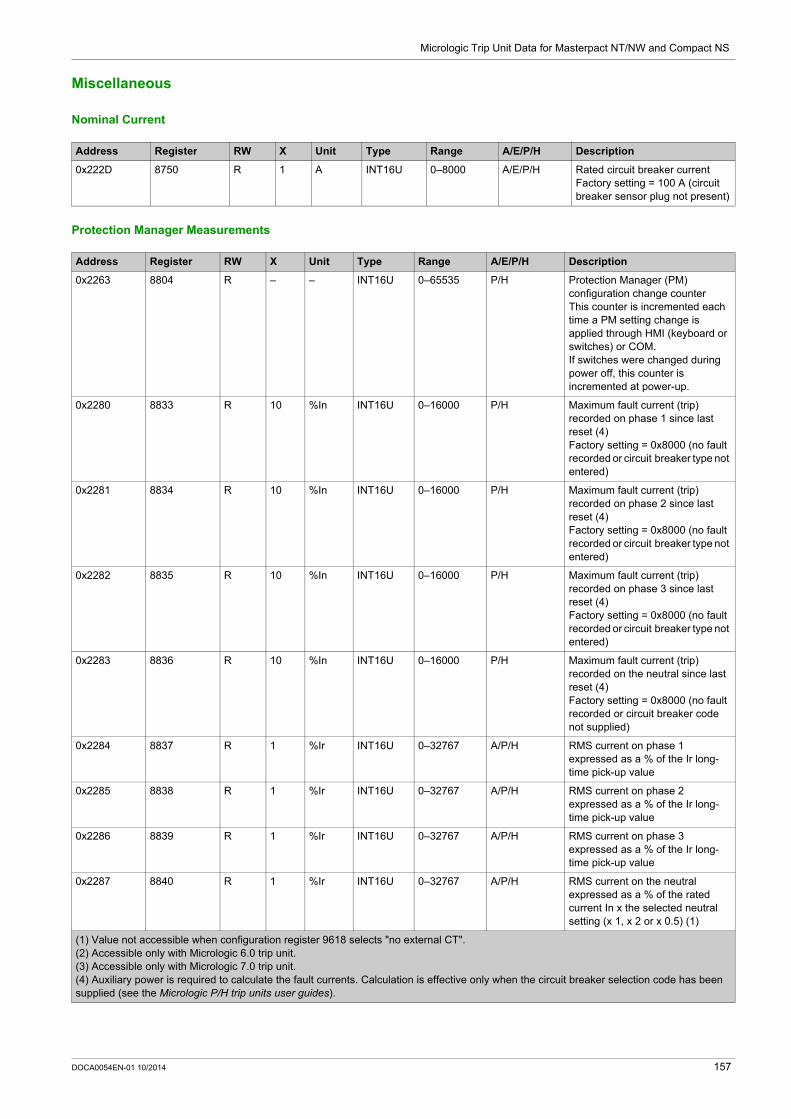
Micrologic Trip Unit Data for Masterpact NT/NW and Compact NS
Miscellaneous
Nominal Current
Protection Manager Measurements
Address Register RW X Unit Type Range A/E/P/H Description
0x222D 8750 R 1 A INT16U 0–8000 A/E/P/H Rated circuit breaker currentFactory setting = 100 A (circuit breaker sensor plug not present)
Address Register RW X Unit Type Range A/E/P/H Description
0x2263 8804 R – – INT16U 0–65535 P/H Protection Manager (PM) configuration change counterThis counter is incremented each time a PM setting change is applied through HMI (keyboard or switches) or COM.If switches were changed during power off, this counter is incremented at power-up.
0x2280 8833 R 10 %In INT16U 0–16000 P/H Maximum fault current (trip) recorded on phase 1 since last reset (4)Factory setting = 0x8000 (no fault recorded or circuit breaker type not entered)
0x2281 8834 R 10 %In INT16U 0–16000 P/H Maximum fault current (trip) recorded on phase 2 since last reset (4)Factory setting = 0x8000 (no fault recorded or circuit breaker type not entered)
0x2282 8835 R 10 %In INT16U 0–16000 P/H Maximum fault current (trip) recorded on phase 3 since last reset (4)Factory setting = 0x8000 (no fault recorded or circuit breaker type not entered)
0x2283 8836 R 10 %In INT16U 0–16000 P/H Maximum fault current (trip) recorded on the neutral since last reset (4)Factory setting = 0x8000 (no fault recorded or circuit breaker code not supplied)
0x2284 8837 R 1 %Ir INT16U 0–32767 A/P/H RMS current on phase 1 expressed as a % of the Ir long-time pick-up value
0x2285 8838 R 1 %Ir INT16U 0–32767 A/P/H RMS current on phase 2 expressed as a % of the Ir long-time pick-up value
0x2286 8839 R 1 %Ir INT16U 0–32767 A/P/H RMS current on phase 3 expressed as a % of the Ir long-time pick-up value
0x2287 8840 R 1 %Ir INT16U 0–32767 A/P/H RMS current on the neutral expressed as a % of the rated current In x the selected neutral setting (x 1, x 2 or x 0.5) (1)
(1) Value not accessible when configuration register 9618 selects "no external CT".(2) Accessible only with Micrologic 6.0 trip unit.(3) Accessible only with Micrologic 7.0 trip unit.(4) Auxiliary power is required to calculate the fault currents. Calculation is effective only when the circuit breaker selection code has been supplied (see the Micrologic P/H trip units user guides).
DOCA0054EN-01 10/2014 157

Micrologic Trip Unit Data for Masterpact NT/NW and Compact NS
Battery Status
The following table represents the battery charge status:
Time Remaining Until Long-Time Tripping
Time remaining until long-time tripping is evaluated every second. If another protection is tripped, then time remaining until long-time tripping continues to be evaluated.
Phase Rotation
Language
This register sets the language used by the trip unit. It may be modified through the trip unit keypad. The factory setting is English but it may be factory set if necessary.
0x2288 8841 R 1 %Ig INT16U 0–32767 A/P/H "Residual" ground-fault current expressed as a % of the Ig ground-fault protection pick-up value (2)
0x2289 8842 R 100 %Idn INT16U 0–32767 A/P/H Earth-leakage current expressed as a % of the IN earth-leakage protection pick-up value (3)
Address Register RW X Unit Type Range A/E/P/H Description
(1) Value not accessible when configuration register 9618 selects "no external CT".(2) Accessible only with Micrologic 6.0 trip unit.(3) Accessible only with Micrologic 7.0 trip unit.(4) Auxiliary power is required to calculate the fault currents. Calculation is effective only when the circuit breaker selection code has been supplied (see the Micrologic P/H trip units user guides).
Address Register RW X Unit Type Range A/E/P/H Description
0x228A 8843 R 1 % INT16U 0–100 A/E/P/H Battery-charge indicator:100 % = U > 2800 mV50 % = 2200 < U < 2800 mV0 % = U < 2200 mV
Address Register RW X Unit Type Range A/E/P/H Description
0x22A0–0x22A1
8865–8866
R 10 s MOD10000
– P/H Time remaining until long-time tripping
Address Register RW X Unit Type Range A/E/P/H Description
0x22A7 8872 R – – INT16U – P/H Phase rotation:0 = ABC (123)1 = ACB (132)
Address Register RW X Unit Type Range A/E/P/H Bit Description
0x258D 9614 RW – – INT16U – P/H 0 French
1 US English
2 UK English
3 German
4 Spanish
5 Italian
7 Chinese
8 Russian
9 Optional language available on order from Schneider Electric
10–15 Reserved
158 DOCA0054EN-01 10/2014

Micrologic Trip Unit Data for Masterpact NT/NW and Compact NS
Nominal Frequency
This register rates the circuit breaker operating frequency required by the protection manager to disable phase rotation protection for 400 Hz distribution system.
Address Register RW X Unit Type Range A/E/P/H Bit Description
0x258E 9615 RW – – INT16U – P/H 0 50 / 60 Hz (factory setting)
1–2 Reserved
3 400 Hz
4–15 Reserved
DOCA0054EN-01 10/2014 159

Micrologic Trip Unit Data for Masterpact NT/NW and Compact NS
Micrologic Trip Unit Files
Section 4.2Micrologic Trip Unit Files
What Is in This Section?
This section contains the following topics:
Topic Page
File Mechanism 161
Protection Event Log 163
Metering Event Log 165
Maintenance Protection Event Log 167
Maintenance Metering Event Log 169
Minimum/Maximum Event Log 171
Waveform Capture 173
Fault Waveform Capture 176
160 DOCA0054EN-01 10/2014

Micrologic Trip Unit Data for Masterpact NT/NW and Compact NS
File Mechanism
Overview
Micrologic trip unit stores events and waveform in different files.
Access
These files can be read with the Modbus function code 20 (0x14): Read file record.
There are 2 types of files: files with dynamic number of records added in a FIFO stack and managed with sequence registers. In
this case, the record number of the last record is defined with these sequence registers. files with a fixed number n of records. In this case, all record numbers and their descriptions are detailed.
The Modbus function 20 (0x14) is handled n times on the n desired records numbers.
Structure
The following graphic shows the structure of a file:
A file is made up of records, with a maximum of 100 records. All records in a file have the same structure and size.
The descriptor is made up of the following 2 read zones: 1 read zone for file configuration (Header) that gives information about size of file and records 1 read zone for file characteristics (Status) that gives information about record numbers
Descriptors are updated each time new record is added to the file.
Sequence Registers Description
The file characteristics (Status) makes available to the supervisor 2 sequence registers that indicate the first and last records added in the file. They enable the supervisor to determine whether certain records were deleted before they could be read.
The sequence number for the last record increments from 1 to 8000 each time a new record is added to the file.
When the file is full (maximum of 100 records), the new record overwrites the oldest record. The sequence number for the last record continues to increment normally. When the oldest record is overwritten, the sequence number for the first record also increments.
When the sequence number reaches 8000, the next sequence number will be 1.
DOCA0054EN-01 10/2014 161

Micrologic Trip Unit Data for Masterpact NT/NW and Compact NS
Read File Record Example
The Read File Record function is used to access in a standardized manner the file information. This example presents a request to read the most recent record in the event log of the protection manager.
The following table shows how to read the event log of the file no. 20 (0x0014). This file is made up of 100 records. Each record is made up of 9 registers, thus the record length is 9 (0x0009). The Modbus address of the Modbus slave is 47 = 0x2F.
The sequence number of last record in the file (the most recent) is the content of register 9921. Consider 0x1234 for the content of register 9921.
Master Request Slave Reply
Field Name Example Field Name Example
Modbus slave address 0x2F Modbus slave address 0x2F
Function code 0x14 Function code 0x14
Data length in bytes 0x07 Data length in bytes 0x14
Reference type 0x06 File reply length 0x13
File number 0x0014 Reference type 0x06
Record number 0x1234 Record data 9x2 bytes data
Record length 0x0009 CRC (MSB) 0xXX
CRC (MSB) 0xXX CRC (LSB) 0xXX
CRC (LSB) 0xXX –
162 DOCA0054EN-01 10/2014

Micrologic Trip Unit Data for Masterpact NT/NW and Compact NS
Protection Event Log
General Description
The system stores the events that concern the protection manager (trips, alarms) in the file no. 20.
This file is made up of 100 records and each record is made up of 9 registers.
File Header
The following table describes the file header content:
File Status
The following table describes the file status content:
Address Register RW X Unit Type Range A/E/P/H Description
0x26AB 9900 RW – – INT16U – P/H File status:0x0000 = file disabled0xFFFF = file enabled (factory setting)
0x26AC 9901 R – – INT16U – P/H Type of file:20 = protection event log
0x26AD 9902 R 1 – INT16U – P/H Size of a file = 100 records
0x26AE 9903 R 1 – INT16U – P/H Size of a record = 9 registers
0x26AF 9904 R – – INT16U 1 P/H File filling mode:0 = circular
Address Register RW X Unit Type Range A/E/P/H Description
0x26BB 9916 R 1 – INT16U – P/H Size of a file = 100 records
0x26BC 9917 R 1 – INT16U – P/H Size of a record = 9 registers
0x26BD 9918 R 1 – INT16U – P/H 0x0000 = file OK0x000A = record size smaller than expected0x0014 = record size larger than expected0x001E = insufficient memory0x00FA = internal error0x00FD = corrupted allocation table0x00FE = configuration zero0x00FF = invalid configuration0xFC00 = invalid file number0xFD00 = invalid record number0xFE00 = file not supported0xFF00 = cannot allocate file
0x26BE 9919 R 1 – INT16U 0–100 P/H Number of records in the file
0x26BF 9920 R 1 – INT16U 0–8000 P/H Sequence number of first record in the file (the oldest)
0x26C0 9921 R 1 – INT16U 0–8000 P/H Sequence number of last record in the file (the most recent)
0x26C1– 0x26C3
9922– 9924 R – – DATE – P/H Date the last file was reset.Factory setting = 0x8000 0x8000 0x8000
DOCA0054EN-01 10/2014 163

Micrologic Trip Unit Data for Masterpact NT/NW and Compact NS
Protection Event Record
The following table shows the format of one record in the protection event log.
Registers Type Bits Description
1–4 XDATE – Event date
5 INT16U – Event number: alarm code (see page 122) or trip code (see page 124)
6 INT16U – Event characteristics for protection event log (1)
7 INT16U 0–7 1 = event of the over type2 = alarm of the under type3 = alarm of the minimum type4 = alarm of the maximum type5 = alarm of the assorted type
8–11 1 = start of an event2 = end of an alarm
12–15 Alarms 1100–1106 have a priority 3. For other alarms, the value contained in these 4 bits represents the priority linked to the event (if applicable and depending on the alarm configuration).
8 INT16U – Logging register associated to the alarm (2)
9 INT16U – Action register associated to the alarm (2)
(1) For event numbers 1000–1004, the data is the value of the fault current interrupted by the circuit breaker. For all other protection events, this value is forced to 32768.(2) Registers 8 and 9 are a copy of the alarm configuration registers at the moment the event occurred. These registers depend entirely on the user configurations. For the events 1100–1106, these registers are forced to 32768.
164 DOCA0054EN-01 10/2014

Micrologic Trip Unit Data for Masterpact NT/NW and Compact NS
Metering Event Log
General Description
The system stores the events that concern the metering manager (Analog predefined alarms 1 to 53) in the file 10.
This file is made up of 100 records and each record is made up of 9 registers.
File Header
The following table describes the file header content:
File Status
The following table describes the file status content:
Address Register RW X Unit Type Range A/E/P/H Description
0x1BFB 7164 RW – – INT16U – H File status:0x0000 = file disabled0xFFFF = file enabled (factory setting)
0x1BFC 7165 R – – INT16U – H Type of file:10 = metering event log
0x1BFD 7166 R 1 – INT16U – H Size of a file = 100 records
0x1BFE 7167 R 1 – INT16U – H Size of a record = 9 registers
0x1BFF 7168 R – – INT16U 1 H File filling mode:0 = circular
Address Register RW X Unit Type Range A/E/P/H Description
0x1C0B 7180 R 1 – INT16U – H Size of a file = 100 records
0x1C0C 7181 R 1 – INT16U – H Size of a record = 9 registers
0x1C0D 7182 R 1 – INT16U – H 0x0000 = file OK0x000A = record size smaller than expected0x0014 = record size larger than expected0x001E = insufficient memory0x00FA = internal error0x00FD = corrupted allocation table0x00FE = configuration zero0x00FF = invalid configuration0xFC00 = invalid file number0xFD00 = invalid record number0xFE00 = file not supported0xFF00 = cannot allocate file
0x1C0E 7183 R 1 – INT16U 0–100 H Number of records in the file
0x1C0F 7184 R 1 – INT16U 0–8000 H Sequence number of first record in the file (the oldest)
0x1C10 7185 R 1 – INT16U 0–8000 H Sequence number of last record in the file (the most recent)
0x1C11– 0x1C13
7186– 7188 R – – DATE – H Date the last file was reset.Factory setting = 0x8000 0x8000 0x8000
DOCA0054EN-01 10/2014 165

Micrologic Trip Unit Data for Masterpact NT/NW and Compact NS
Metering Event Record
The following table shows the format of 1 record in the metering log:
Registers Type Bits Description
1–4 XDATE – Event date
5 INT16U – Event number: analog predefined alarms 1–53 (see page 125)
6 INT16U – Extreme value
7 INT16U 0–7 1 = alarm of the over type2 = alarm of the under type3 = alarm of the equal to type4 = alarm of the different from type5 = all other alarms
8–11 1 = start of an alarm2 = end of an alarm
12–15 Alarms 1100–1106 have a priority 3. For other alarms, the value contained in these 4 bits represents the priority linked to the event (if applicable and depending on the alarm configuration).
8 INT16U – Logging register associated to the alarm (1)
9 INT16U – Action register associated to the alarm (1)
(1) Registers 8 and 9 are a copy of the alarm configuration registers at the moment the event occurred. These registers depend entirely on the user configurations. For the events 1100–1106, these registers are forced to 32768.
166 DOCA0054EN-01 10/2014
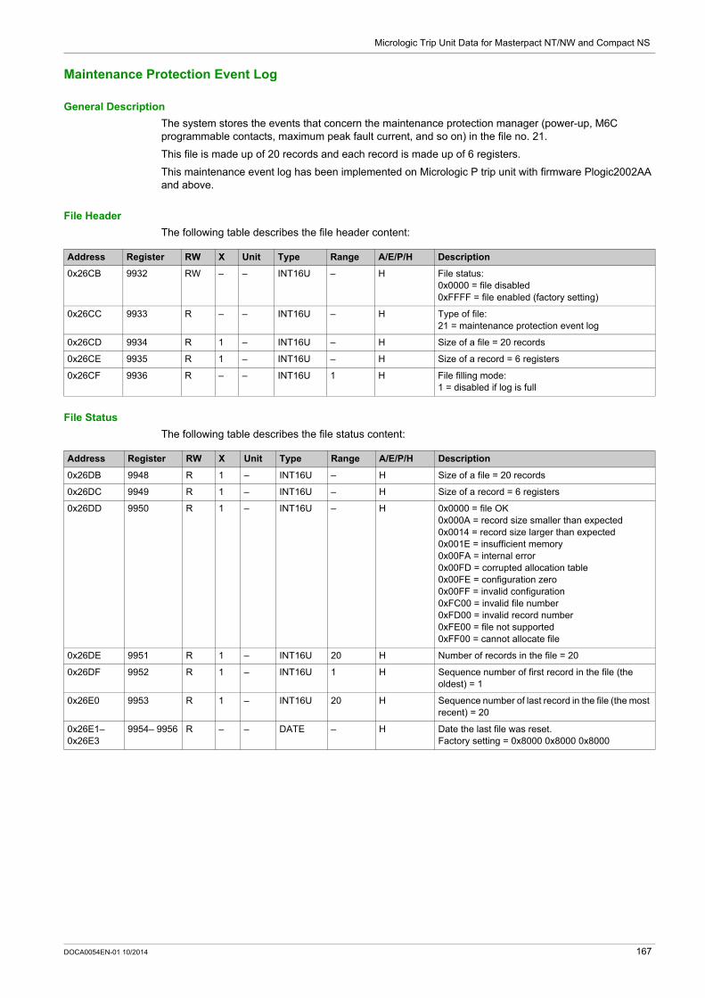
Micrologic Trip Unit Data for Masterpact NT/NW and Compact NS
Maintenance Protection Event Log
General Description
The system stores the events that concern the maintenance protection manager (power-up, M6C programmable contacts, maximum peak fault current, and so on) in the file no. 21.
This file is made up of 20 records and each record is made up of 6 registers.
This maintenance event log has been implemented on Micrologic P trip unit with firmware Plogic2002AA and above.
File Header
The following table describes the file header content:
File Status
The following table describes the file status content:
Address Register RW X Unit Type Range A/E/P/H Description
0x26CB 9932 RW – – INT16U – H File status:0x0000 = file disabled0xFFFF = file enabled (factory setting)
0x26CC 9933 R – – INT16U – H Type of file:21 = maintenance protection event log
0x26CD 9934 R 1 – INT16U – H Size of a file = 20 records
0x26CE 9935 R 1 – INT16U – H Size of a record = 6 registers
0x26CF 9936 R – – INT16U 1 H File filling mode:1 = disabled if log is full
Address Register RW X Unit Type Range A/E/P/H Description
0x26DB 9948 R 1 – INT16U – H Size of a file = 20 records
0x26DC 9949 R 1 – INT16U – H Size of a record = 6 registers
0x26DD 9950 R 1 – INT16U – H 0x0000 = file OK0x000A = record size smaller than expected0x0014 = record size larger than expected0x001E = insufficient memory0x00FA = internal error0x00FD = corrupted allocation table0x00FE = configuration zero0x00FF = invalid configuration0xFC00 = invalid file number0xFD00 = invalid record number0xFE00 = file not supported0xFF00 = cannot allocate file
0x26DE 9951 R 1 – INT16U 20 H Number of records in the file = 20
0x26DF 9952 R 1 – INT16U 1 H Sequence number of first record in the file (the oldest) = 1
0x26E0 9953 R 1 – INT16U 20 H Sequence number of last record in the file (the most recent) = 20
0x26E1– 0x26E3
9954– 9956 R – – DATE – H Date the last file was reset.Factory setting = 0x8000 0x8000 0x8000
DOCA0054EN-01 10/2014 167

Micrologic Trip Unit Data for Masterpact NT/NW and Compact NS
Maintenance Protection Event Record
The maintenance protection event log has a fixed number of records and all record has a fixed number of registers:
Record Number Registers Type Description
1 1–4 XDATE Last power loss
5–6 – Reserved
2 1–3 DATE Date/time of last counter reset
4 INT16U Number of output operations for relay 1
5–6 – Reserved
3–6 1–3 DATE Date/time of last counter reset
4 INT16U Number of output operations for relay 2–5
5–6 – Reserved
7 1–3 DATE Date/time of last counter reset
4 INT16U Number of output operations for relay 6
5–6 – Reserved
8 1–3 DATE Date/time of last record updated
4 INT16U Worst contact wear
5–6 – Reserved
9 1–3 DATE Date/time of last record updated
4 INT16U Maximum reverse power
5–6 – Reserved
10 1–3 DATE Date/time of last record updated
4 INT16U Battery indicator (see page 158)
5–6 – Reserved
11 1–3 DATE Date/time of last record updated
4 INT16U Number of power losses
5–6 – Reserved
12–15 1–6 – Reserved
16 1–3 DATE Date/time of last record updated
4 INT16U Number of maximum resets
5–6 – Reserved
17 1–6 – Reserved
18 1–3 DATE Date/time of last record updated
4 INT16U Maximum peak fault current breaker ever opened
5–6 – Reserved
19–20 1–6 – Reserved
168 DOCA0054EN-01 10/2014

Micrologic Trip Unit Data for Masterpact NT/NW and Compact NS
Maintenance Metering Event Log
General Description
The system stores the events that concern the maintenance metering manager (counter reset, and so on) in the file no. 12.
This file is made up of 20 records and each record is made up of 6 registers.
File Header
The following table describes the file header content:
File Status
The following table describes the file status content:
Address Register RW X Unit Type Range A/E/P/H Description
0x1C3B 7228 RW – – INT16U – H File status:0x0000 = file disabled0xFFFF = file enabled (factory setting)
0x1C3C 7229 R – – INT16U – H Type of file:12 = maintenance metering event log
0x1C3D 7230 R 1 – INT16U – H Size of a file = 20 records
0x1C3E 7231 R 1 – INT16U – H Size of a record = 6 registers
0x1C3F 7232 R – – INT16U 1 H File filling mode:1 = disabled if log is full
Address Register RW X Unit Type Range A/E/P/H Description
0x1C4B 7244 R 1 – INT16U – H Size of a file = 20 records
0x1C4C 7245 R 1 – INT16U – H Size of a record = 6 registers
0x1C4D 7246 R 1 – INT16U – H 0x0000 = file OK0x000A = record size smaller than expected0x0014 = record size larger than expected0x001E = insufficient memory0x00FA = internal error0x00FD = corrupted allocation table0x00FE = configuration zero0x00FF = invalid configuration0xFC00 = invalid file number0xFD00 = invalid record number0xFE00 = file not supported0xFF00 = cannot allocate file
0x1C4E 7247 R 1 – INT16U 20 H Number of records in the file = 20
0x1C4F 7248 R 1 – INT16U 1 H Sequence number of first record in the file (the oldest) = 1
0x1C50 7249 R 1 – INT16U 20 H Sequence number of last record in the file (the most recent) = 20
0x1C51– 0x1C53
7250– 7252 R – – DATE – H Date the last file was reset.Factory setting = 0x8000 0x8000 0x8000
DOCA0054EN-01 10/2014 169

Micrologic Trip Unit Data for Masterpact NT/NW and Compact NS
Maintenance Metering Event Record
The maintenance metering event log has a fixed number of records and all record has a fixed number of registers:
Record Number Registers Type Description
1 1–3 DATE Date/time of last counter reset
4 INT16U Number of minimum resets
5–6 – Reserved
2 1–3 DATE Date/time of last counter reset
4 INT16U Number of maximum resets
5–6 – Reserved
3 1–3 DATE Date/time of last counter reset
4 INT16U Number of peak current demand resets
5–6 – Reserved
4 1–3 DATE Date/time of last counter reset
4 INT16U Number of peak power demand resets
5–6 – Reserved
5 1–3 DATE Date/time of last counter reset
4 INT16U Number of energy resets
5–6 – Reserved
6–20 1–6 – Reserved
170 DOCA0054EN-01 10/2014
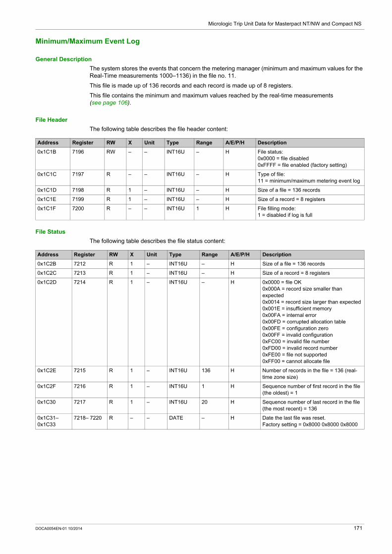
Micrologic Trip Unit Data for Masterpact NT/NW and Compact NS
Minimum/Maximum Event Log
General Description
The system stores the events that concern the metering manager (minimum and maximum values for the Real-Time measurements 1000–1136) in the file no. 11.
This file is made up of 136 records and each record is made up of 8 registers.
This file contains the minimum and maximum values reached by the real-time measurements (see page 106).
File Header
The following table describes the file header content:
File Status
The following table describes the file status content:
Address Register RW X Unit Type Range A/E/P/H Description
0x1C1B 7196 RW – – INT16U – H File status:0x0000 = file disabled0xFFFF = file enabled (factory setting)
0x1C1C 7197 R – – INT16U – H Type of file:11 = minimum/maximum metering event log
0x1C1D 7198 R 1 – INT16U – H Size of a file = 136 records
0x1C1E 7199 R 1 – INT16U – H Size of a record = 8 registers
0x1C1F 7200 R – – INT16U 1 H File filling mode:1 = disabled if log is full
Address Register RW X Unit Type Range A/E/P/H Description
0x1C2B 7212 R 1 – INT16U – H Size of a file = 136 records
0x1C2C 7213 R 1 – INT16U – H Size of a record = 8 registers
0x1C2D 7214 R 1 – INT16U – H 0x0000 = file OK0x000A = record size smaller than expected0x0014 = record size larger than expected0x001E = insufficient memory0x00FA = internal error0x00FD = corrupted allocation table0x00FE = configuration zero0x00FF = invalid configuration0xFC00 = invalid file number0xFD00 = invalid record number0xFE00 = file not supported0xFF00 = cannot allocate file
0x1C2E 7215 R 1 – INT16U 136 H Number of records in the file = 136 (real-time zone size)
0x1C2F 7216 R 1 – INT16U 1 H Sequence number of first record in the file (the oldest) = 1
0x1C30 7217 R 1 – INT16U 20 H Sequence number of last record in the file (the most recent) = 136
0x1C31– 0x1C33
7218– 7220 R – – DATE – H Date the last file was reset.Factory setting = 0x8000 0x8000 0x8000
DOCA0054EN-01 10/2014 171

Micrologic Trip Unit Data for Masterpact NT/NW and Compact NS
Minimum/Maximum Event Record
The minimum/maximum event log has a fixed number of records and all record has a fixed number of registers:
Record Number Registers Type Description
1 1 INT16U Last minimum value (register 1300)
2–4 DATE Date/time of last minimum value
5 INT16U Last maximum value (register 1600)
6–8 DATE Date/time of last maximum value
2 1 INT16U Last minimum value (register 1301)
2–4 DATE Date/time of last minimum value
5 INT16U Last maximum value (register 1601)
6–8 DATE Date/time of last maximum value
3–135 1 INT16U Last minimum value (register 130x)
2–4 DATE Date/time of last minimum value
5 INT16U Last maximum value (register 160x)
6–8 DATE Date/time of last maximum value
136 1 INT16U Last minimum value (register 1435)
2–4 DATE Date/time of last minimum value
5 INT16U Last maximum value (register 1735)
6–8 DATE Date/time of last maximum value
172 DOCA0054EN-01 10/2014

Micrologic Trip Unit Data for Masterpact NT/NW and Compact NS
Waveform Capture
General Description
The system stores the variables V1N, V2N, V3N, I1, I2, I3, IN during 4 cycles (64 points per cycles) in the file no. 5.
This file consists of a fixed number of records (29). All records are of similar size that is 64 registers wide.
The capture is triggered as follows: manually (user request) by using the command Forcelog (see the Masterpact Legacy Modbus User
Guide) automatically attached to analog predefined alarms (1 to 53) by setting the log action to 1
(see page 125)
File Header
The following table describes the file header content:
File Status
The following table describes the file status content:
Address Register RW X Unit Type Range A/E/P/H Description
0x1BDB 7132 RW – – INT16U – H File status:0x0000 = file disabled0xFFFF = file enabled (factory setting)
0x1BDC 7133 R – – INT16U – H Type of file:5 = waveform capture
0x1BDD 7134 R 1 – INT16U – H Size of a file = 29 records
0x1BDE 7135 R 1 – INT16U – H Size of a record = 64 registers
0x1BDF 7136 R – – INT16U 1 H File filling mode:0 = circular1 = disabled if log is full
0x1BE0 7137 R 1 – INT16U – H Number of cycle segments:1 = 4 cycles for waveform capture
0x1BE1 7138 R 1 – INT16U – H Number of cycles before capture:2 = waveform capture and fault waveform capture
0x1BE2 7139 R 1 – INT16U – H Number of points per cycle:64 = waveform capture
Address Register RW X Unit Type Range A/E/P/H Description
0x1BEB 7148 R 1 – INT16U – H Size of a file = 29 records
0x1BEC 7149 R 1 – INT16U – H Size of a record = 64 registers
0x1BED 7150 R 1 – INT16U – H 0x0000 = file OK0x000A = record size smaller than expected0x0014 = record size larger than expected0x001E = insufficient memory0x00FA = internal error0x00FD = corrupted allocation table0x00FE = configuration zero0x00FF = invalid configuration0xFC00 = invalid file number0xFD00 = invalid record number0xFE00 = file not supported0xFF00 = cannot allocate file
0x1BEE 7151 R 1 – INT16U – H Number of records in the file = 29
0x1BEF 7152 R 1 – INT16U – H Sequence number of first record in the file (the oldest) = 1
0x1BF0 7153 R 1 – INT16U – H Sequence number of last record in the file (the most recent) = 29
0x1BF1– 0x1BF3
7154– 7156 R – – DATE – H Date the last file was reset.Factory setting = 0x8000 0x8000 0x8000
DOCA0054EN-01 10/2014 173

Micrologic Trip Unit Data for Masterpact NT/NW and Compact NS
Waveform Record
The waveform capture has a fixed number of records and all record has a fixed number of registers:
Voltage Calculation
Apply the following rule to derive the voltage: on phase 1:
Sample (Volt) = [(sample – register no. 16 of first record) x register no. 15 of first record.]/register no. 29 of first record.
on phase 2:Sample (Volt) = [(sample – register no. 18 of first record) x register no. 17 of first record.]/register no. 29 of first record.
on phase 3:Sample (Volt) = [(sample – register no. 20 of first record) x register no. 19 of first record.]/register no. 29 of first record.
Record Number Registers Type Description
1 1–4 XDATE Extended date/time
5–11 – Reserved
12 INT16U Id of WFC trigger: analog predefined alarm 1–53 (see page 125)Available with firmware HLogic2005AF
13 – System type: 31, 40 or 41 (see page 151)
14 A Breaker nominal current
15 SFIXPT Voltage multiplier for phase 1
16 INT16 Voltage offset for phase 1
17 SFIXPT Voltage multiplier for phase 2
18 INT16 Voltage offset for phase 2
19 SFIXPT Voltage multiplier for phase 3
20 INT16 Voltage offset for phase 3
21 SFIXPT Current multiplier for phase 1
22 INT16 Current offset for phase 1
23 SFIXPT Current multiplier for phase 2
24 INT16 Current offset for phase 2
25 SFIXPT Current multiplier for phase 3
26 INT16 Current offset for phase 3
27 SFIXPT Current multiplier for neutral
28 INT16 Current offset for neutral
29 INT16U Scaling factor used for SFIXPT math on voltage samples
30 INT16U Scaling factor used for SFIXPT math on phase-current samples
31 INT16U Scaling factor used for SFIXPT math on neutral-current samples
32–64 – Not used
2–5 1–64 INT16U Voltage V1N sample points (64 points - 4 cycles)
6–9 1–64 INT16U Voltage V2N sample points (64 points - 4 cycles)
10–13 1–64 INT16U Voltage V3N sample points (64 points - 4 cycles)
14–17 1–64 INT16U Current I1 sample points (64 points - 4 cycles)
18–21 1–64 INT16U Current I2 sample points (64 points - 4 cycles)
22–25 1–64 INT16U Current I3 sample points (64 points - 4 cycles)
26–29 1–64 INT16U Current IN sample points (64 points - 4 cycles)Valid only with system type 41
174 DOCA0054EN-01 10/2014

Micrologic Trip Unit Data for Masterpact NT/NW and Compact NS
Current Calculation
Apply the following rule to derive the current: on phase 1:
Sample (Ampere) = [(sample – register no. 22 of first record) x register no. 21 of first record.]/register no. 30 of first record.
on phase 2:Sample (Ampere) = [(sample – register no. 24 of first record) x register no. 23 of first record.]/register no. 30 of first record.
on phase 3:Sample (Ampere) = [(sample – register no. 26 of first record) x register no. 25 of first record.]/register no. 30 of first record.
on neutral:Sample (Ampere) = [(sample – register no. 27 of first record) x register no. 28 of first record.]/register no. 31 of first record.
DOCA0054EN-01 10/2014 175

Micrologic Trip Unit Data for Masterpact NT/NW and Compact NS
Fault Waveform Capture
General Description
The system stores the variables V1N, V2N, V3N, I1, I2, I3, IN during 12 cycles (16 points per cycles) in the file no. 22.
This file consists of a fixed number of records (22). All records are of similar size that is 64 registers wide.
The capture is triggered automatically attached to alarms (1000–1030) by setting the log action to 1 (see page 124).
File Header
The following table describes the file header content:
File Status
The following table describes the file status content:
Address Register RW X Unit Type Range A/E/P/H Description
0x26EB 9964 RW – – INT16U – H File status:0x0000 = file disabled0xFFFF = file enabled (factory setting)
0x26EC 9965 R – – INT16U – H Type of file:22 = fault waveform capture
0x26ED 9966 R 1 – INT16U – H Size of a file = 22 records
0x26EE 9967 R 1 – INT16U – H Size of a record = 64 registers
0x26EF 9968 R – – INT16U 1 H File filling mode:0 = circular1 = disabled if log is full
0x26F0 9969 R 1 – INT16U – H Number of cycle segments:1 = 12 cycles for fault waveform capture
0x26F1 9970 R 1 – INT16U – H Number of cycles before capture:2 = waveform capture and fault waveform capture
0x26F2 9971 R 1 – INT16U – H Number of points per cycle:16 = fault waveform capture
Address Register RW X Unit Type Range A/E/P/H Description
0x26FB 9980 R 1 – INT16U – H Size of a file = 22 records
0x26FC 9981 R 1 – INT16U – H Size of a record = 64 registers
0x26FD 9982 R 1 – INT16U – H 0x0000 = file OK0x000A = record size smaller than expected0x0014 = record size larger than expected0x001E = insufficient memory0x00FA = internal error0x00FD = corrupted allocation table0x00FE = configuration zero0x00FF = invalid configuration0xFC00 = invalid file number0xFD00 = invalid record number0xFE00 = file not supported0xFF00 = cannot allocate file
0x26FE 9983 R 1 – INT16U – H Number of records in the file = 22
0x26FF 9984 R 1 – INT16U – H Sequence number of first record in the file (the oldest) = 1
0x2700 9985 R 1 – INT16U – H Sequence number of last record in the file (the most recent) = 22
0x2701– 0x2703
9986– 9988 R – – DATE – H Date the last file was reset.Factory setting = 0x8000 0x8000 0x8000
176 DOCA0054EN-01 10/2014

Micrologic Trip Unit Data for Masterpact NT/NW and Compact NS
Fault Waveform Record
The fault waveform capture has a fixed number of records and all record has a fixed number of registers:
Voltage Calculation
Apply the following rule to derive the voltage: on phase 1:
Sample (Volt) = [(sample – register no. 16 of first record) x register no. 15 of first record.]/register no. 29 of first record.
on phase 2:Sample (Volt) = [(sample – register no. 18 of first record) x register no. 17 of first record.]/register no. 29 of first record.
on phase 3:Sample (Volt) = [(sample – register no. 20 of first record) x register no. 19 of first record.]/register no. 29 of first record.
Record Number Registers Type Description
1 1–4 XDATE Extended date/time
5–11 – Reserved
12 INT16U Id of fault WFC trigger: Alarm number 1000 to 1031 (see page 124)
13 – System type: 31, 40 or 41 (see page 151)
14 A Breaker nominal current
15 SFIXPT Voltage multiplier for phase 1
16 INT16 Voltage offset for phase 1
17 SFIXPT Voltage multiplier for phase 2
18 INT16 Voltage offset for phase 2
19 SFIXPT Voltage multiplier for phase 3
20 INT16 Voltage offset for phase 3
21 SFIXPT Current multiplier for phase 1
22 INT16 Current offset for phase 1
23 SFIXPT Current multiplier for phase 2
24 INT16 Current offset for phase 2
25 SFIXPT Current multiplier for phase 3
26 INT16 Current offset for phase 3
27 SFIXPT Current multiplier for neutral
28 INT16 Current offset for neutral
29 INT16U Scaling factor used for SFIXPT math on voltage samples
30 INT16U Scaling factor used for SFIXPT math on phase current samples
31 INT16U Scaling factor used for SFIXPT math on neutral current samples
32–64 – Not used
2–4 1–64 INT16U Voltage V1N sample points (16 points - 12 cycles)
5–7 1–64 INT16U Voltage V2N sample points (16 points - 12 cycles)
8–10 1–64 INT16U Voltage V3N sample points (16 points - 12 cycles)
11–13 1–64 INT16U Current I1 sample points (16 points - 12 cycles)
14–16 1–64 INT16U Current I2 sample points (16 points - 12 cycles)
17–19 1–64 INT16U Current I3 sample points (16 points - 12 cycles)
20–22 1–64 INT16U Current IN sample points (16 points - 12 cycles)Valid only with system type 41
DOCA0054EN-01 10/2014 177

Micrologic Trip Unit Data for Masterpact NT/NW and Compact NS
Current Calculation
Apply the following rule to derive the current: on phase 1:
Sample (Ampere) = [(sample – register no. 22 of first record) x register no. 21 of first record.]/register no. 30 of first record.
on phase 2:Sample (Ampere) = [(sample – register no. 24 of first record) x register no. 23 of first record.]/register no. 30 of first record.
on phase 3:Sample (Ampere) = [(sample – register no. 26 of first record) x register no. 25 of first record.]/register no. 30 of first record.
on neutral:Sample (Ampere) = [(sample – register no. 27 of first record) x register no. 28 of first record.]/register no. 31 of first record.
178 DOCA0054EN-01 10/2014

Micrologic Trip Unit Data for Masterpact NT/NW and Compact NS
Micrologic Trip Unit Commands
Section 4.3Micrologic Trip Unit Commands
Introduction
This section describes the Micrologic trip unit commands.
What Is in This Section?
This section contains the following topics:
Topic Page
List of Micrologic Trip Unit Commands and Error Codes 180
Measurement Configuration Commands 181
DOCA0054EN-01 10/2014 179

Micrologic Trip Unit Data for Masterpact NT/NW and Compact NS
List of Micrologic Trip Unit Commands and Error Codes
List of Commands
The following table lists the available Micrologic trip unit commands, their corresponding command codes, and password levels:
For additional commands related to protection settings, refer to Masterpact Modbus Legacy User Guide.
Error Codes
Error codes generated by Micrologic trip units are the generic error codes (see page 55).
Command Command Code Password Level
Set up ENVT presence 46472 Level 4
Reset minimum/maximum 46728 Level 3 or 4
Power flow sign configuration 47240 Level 4
Power factor sign configuration 47241 Level 4
Energy accumulation mode configuration 47242 Level 4
Current demand configuration 47243 Level 4
Power demand configuration 47244 Level 4
Set up nominal voltage Vn display 47245 Level 4
180 DOCA0054EN-01 10/2014

Micrologic Trip Unit Data for Masterpact NT/NW and Compact NS
Measurement Configuration Commands
Set Up ENVT Presence
The user can read the ENVT (External Neutral Voltage Tap) presence parameters at register 3314 (see page 151).
To set up ENVT presence, the user must set up the command registers the following way:
Reset Minimum/Maximum
The reset minimum/maximum command resets the minimum values of real-time measurements (registers 1300 to 1599) and the maximum values of real-time measurements (registers 1600 to 1899) (see page 106).
The reset minimum/maximum command resets the energy measurements (registers 2000 to 2025) (see page 107).
The reset minimum/maximum command resets the peak demand measurements (registers 2200 to 2237) (see page 108).
To reset minimum/maximum values of measurements, the user must set up the command registers the following way:
Address Register X Unit Type Range A/E/P/H Description
0x1F3F 8000 – – INT16U 46472 E/P/H Command code = 46472
0x1F40 8001 – – INT16U 12 E/P/H Number of parameters (bytes) = 12
0x1F41 8002 – – INT16U 4609 E/P/H Destination = 4609 (0x1201)
0x1F42 8003 – – INT16U 1 E/P/H 1
0x1F430x1F44
80048005
– – STRING – E/P/H Level 4 password (factory setting = ‘0000’ = 0x30303030)
0x1F45 8006 – – INT16U 0–1 E/P/H 0 = ENVT is not present1 = ENVT is present
Address Register X Unit Type Range A/E/P/H Bit Description
0x1F3F 8000 – – INT16U 46728 – – Command code = 46728
0x1F40 8001 – – INT16U 12 – – Number of parameters (bytes) = 12
0x1F41 8002 – – INT16U 4609 – – Destination = 4609 (0x1201)
0x1F42 8003 – – INT16U 1 – – 1
0x1F430x1F44
80048005
– – STRING – – – Level 3 or 4 password: For level 4, factory setting =
‘0000’ = 0x30303030 For level 3, factory setting =
‘3333’ = 0x33333333
DOCA0054EN-01 10/2014 181

Micrologic Trip Unit Data for Masterpact NT/NW and Compact NS
Power Flow Sign Configuration
The user can read the power flow sign configuration at register 3316 (see page 151).
To set the power flow sign parameters, the user must set up the command registers the following way:
0x1F45 8006 – – INT16U – – – Reset minimum/maximum of metering variables: To reset the metering
variable, set the bit to 1. To keep the current values,
set the bit to 0.
A/E/P/H 0 Reset minimum/maximum current (I1, I2, I3, IN, Imax, Ig, In, Iavg, and Iunbal)
E/P/H 1 Reset minimum/maximum voltage (V12, V13, V23, V1N, V2N, V3N, VavgL-L, VavgL-N, and Vunbal)
E/P/H 2 Reset minimum/maximum power (active power, reactive power, apparent power, and distortion power)
E/P/H 3 Reset minimum/maximum power factor and cos
E/P/H 4 Reset minimum/maximum total harmonic distortion (THD)
E/P/H 5 Reset peak of current demand
E/P/H 6 Reset peak of active power, reactive power, and apparent power demand
E/P/H 7 Reset minimum/maximum frequency
– 8 Not applicable
E/P/H 9 Reset energy (active, reactive, apparent)
– 10–15 Reserved
Address Register X Unit Type Range A/E/P/H Bit Description
Address Register X Unit Type Range A/E/P/H Description
0x1F3F 8000 – – INT16U 47240 E/P/H Command code = 47240
0x1F40 8001 – – INT16U 12 E/P/H Number of parameters (bytes) = 12
0x1F41 8002 – – INT16U 4609 E/P/H Destination = 4609 (0x1201)
0x1F42 8003 – – INT16U 1 E/P/H 1
0x1F430x1F44
80048005
– – STRING – E/P/H Level 4 password (factory setting = ‘0000’ = 0x30303030)
0x1F45 8006 – – INT16U 0–1 E/P/H Power flow sign:0 = the active power flows from upstream (top) to downstream (bottom) (factory setting)1 = the active power flows from downstream (bottom) to upstream (top).
182 DOCA0054EN-01 10/2014

Micrologic Trip Unit Data for Masterpact NT/NW and Compact NS
Power Factor Sign Configuration
The user can read the power factor sign configuration at register 3318 (see page 151).
To set the power factor sign parameters, the user must set up the command registers the following way:
Energy Accumulation Mode Configuration
The user can read the energy accumulation mode configuration at register 3324 (see page 152).
To set the energy accumulation mode parameters, the user must set up the command registers the following way:
Current Demand Configuration
The user can read the duration of the current demand calculation window at register 3352 (see page 152).
The user can read the current demand parameters from register 2200 to 2207 (see page 108).
To start current demand, the user must set up the command registers the following way:
Address Register X Unit Type Range A/E/P/H Description
0x1F3F 8000 – – INT16U 47241 E Command code = 47241
0x1F40 8001 – – INT16U 12 E Number of parameters (bytes) = 12
0x1F41 8002 – – INT16U 4609 E Destination = 4609 (0x1201)
0x1F42 8003 – – INT16U 1 E 1
0x1F430x1F44
80048005
– – STRING – E Level 4 password (factory setting = ‘0000’ = 0x30303030)
0x1F45 8006 – – INT16U 0–2 E Sign convention for the power factor and the fundamental power factor (cos):0 = IEC convention 2 = IEEE convention (factory setting)
Address Register X Unit Type Range A/E/P/H Description
0x1F3F 8000 – – INT16U 47242 E/P/H Command code = 47242
0x1F40 8001 – – INT16U 12 E/P/H Number of parameters (bytes) = 12
0x1F41 8002 – – INT16U 4609 E/P/H Destination = 4609 (0x1201)
0x1F42 8003 – – INT16U 1 E/P/H 1
0x1F430x1F44
80048005
– – STRING – E/P/H Level 4 password (factory setting = ‘0000’ = 0x30303030)
0x1F45 8006 – – INT16U 0–1 E/P/H Energy accumulation mode:0 = absolute accumulation (factory setting) 1 = signed accumulation
Address Register X Unit Type Range A/E/P/H Description
0x1F3F 8000 – – INT16U 47243 E/P/H Command code = 47243
0x1F40 8001 – – INT16U 12 E/P/H Number of parameters (bytes) = 12
0x1F41 8002 – – INT16U 4609 E/P/H Destination = 4609 (0x1201)
0x1F42 8003 – – INT16U 1 E/P/H 1
0x1F430x1F44
80048005
– – STRING – E/P/H Level 4 password (factory setting = ‘0000’ = 0x30303030)
0x1F45 8006 – Min INT16U 5–60 E/P/H Duration of the current demand calculation window, adjustable in step of 1.The factory setting is 15 minutes (sliding).
DOCA0054EN-01 10/2014 183

Micrologic Trip Unit Data for Masterpact NT/NW and Compact NS
Power Demand Configuration
The user can read the power demand calculation method from register 3354 to 3355 (see page 152).
The user can read the power demand parameters from register 2224 to 2237 (see page 109).
To start power demand, the user must set up the command registers the following way:
Set Up Nominal Primary Voltage Vn Display
The user can read the nominal voltage at register 9616 (see page 153).
To set the nominal primary voltage Vn display parameters, the user must set up the command registers the following way:
Address Register X Unit Type Range A/E/P/H Description
0x1F3F 8000 – – INT16U 47244 E/P/H Command code = 47244
0x1F40 8001 – – INT16U 14 E/P/H Number of parameters (bytes) = 14
0x1F41 8002 – – INT16U 4609 E/P/H Destination = 4609 (0x1201)
0x1F42 8003 – – INT16U 1 E/P/H 1
0x1F430x1F44
80048005
– – STRING – E/P/H Level 4 password (factory setting = ‘0000’ = 0x30303030)
0x1F45 8006 – – INT16U 0–5 E/P/H Power demand calculation method (window type):0 = sliding (factory setting)2 = fixed5 = synchronized to communication
0x1F46 8007 – Min INT16U 5–60 E/P/H Duration of the power demand calculation window, adjustable in step of 1.The factory setting is 15 minutes.
Address Register X Unit Type Range A/E/P/H Description
0x1F3F 8000 – – INT16U 47245 E/P/H Command code = 47245
0x1F40 8001 – – INT16U 12 E/P/H Number of parameters (bytes) = 12
0x1F41 8002 – – INT16U 4609 E/P/H Destination = 4609 (0x1201)
0x1F42 8003 – – INT16U 1 E/P/H 1
0x1F430x1F44
80048005
– – STRING – E/P/H Level 4 password (factory setting = ‘0000’ = 0x30303030)
0x1F45 8006 – V INT16U 0–65535 E/P/H Nominal primary voltage Vn (factory setting = 690 V)
184 DOCA0054EN-01 10/2014

Masterpact NT/NW, Compact NS
BCM ULP Data for Masterpact NT/NW and Compact NS
DOCA0054EN-01 10/2014
BCM ULP Data for Masterpact NT/NW and Compact NS
Chapter 5BCM ULP Data for Masterpact NT/NW and Compact NS
What Is in This Chapter?
This chapter contains the following sections:
Section Topic Page
5.1 BCM ULP Registers 186
5.2 BCM ULP Files 195
5.3 BCM ULP Commands 197
DOCA0054EN-01 10/2014 185

BCM ULP Data for Masterpact NT/NW and Compact NS
BCM ULP Registers
Section 5.1BCM ULP Registers
What Is in This Section?
This section contains the following topics:
Topic Page
BCM ULP Identification 187
Circuit Breaker Status 188
Time-Stamped Information 191
Counters 192
Trip History 193
186 DOCA0054EN-01 10/2014

BCM ULP Data for Masterpact NT/NW and Compact NS
BCM ULP Identification
Product Identification
BCM ULP Identifier
BCM ULP Firmware Version
The BCM ULP firmware version starts with a V character and has the following format: VX.Y.Z.
The firmware version is coded as follows: VX.Y.Z = VX*1000 + Y*100 + Z*10
For example if the value of the register is equal to 2000, the BCM ULP firmware version is equal to V2.0.0.
Address Register RW X Unit Type Range A/E/P/H Description
0x0202 515 R – – INT16U 15139 A/E/P/H Product identification = 15139 for the BCM ULP
Address Register RW X Unit Type Range A/E/P/H Description
0x0215–0x0216
534–535
RW – – STRING 0x0000–0x7F7F
A/E/P/H Short identifier of BCM ULP coded over 4 ASCII charactersFactory setting = 0x0000
0x0217–0x021E
536–543 RW – – STRING 0x0000–0x7F7F
A/E/P/H Long identifier of BCM ULP coded over 16 ASCII charactersFactory setting = 0x0000
Address Register RW X Unit Type Range A/E/P/H Description
0x0240 577 R – – INT16U – A/E/P/H BCM ULP firmware version
DOCA0054EN-01 10/2014 187

BCM ULP Data for Masterpact NT/NW and Compact NS
Circuit Breaker Status
Tripping Cause
The tripping cause register indicates the current status of the trip. If the trip bit is set to 0, then the trip is not active. If the trip bit is set to 1, then the trip is active.
The bit is reset as soon as the circuit breaker is closed again.
Address Register RW X Unit Type Range A/E/P/H Bit Description
0x0289 650 R – – INT16U – – – Tripping cause for basic protection functions
A/E/P/H 0 Long-time protection Ir
A/E/P/H 1 Short-time protection Isd
A/E/P/H 2 Instantaneous-protection Ii
A/E/P/H 3 Ground-fault protection Ig
A/P/H 4 Earth-leakage protection (Vigi)
A/E/P/H 5 Integrated Instantaneous protection
A/E 6 Other protection
P/H Internal failure (temperature)
A/E/P/H 7 Internal failure (overvoltage)
P/H 8 Other protection (see register 651)
– 9–14 Reserved
A/E/P/H 15 If this bit is at 1, bits 0 to 14 are not valid.
0x028A 651 R – – INT16U – – – Tripping cause for advanced protection functions
P/H 0 Current unbalance
P/H 1 Overcurrent phase 1
P/H 2 Overcurrent phase 2
P/H 3 Overcurrent phase 3
P/H 4 Overcurrent on Neutral
P/H 5 Undervoltage
P/H 6 Overvoltage
P/H 7 Voltage unbalance
P/H 8 Overpower
P/H 9 Reverse power
P/H 10 Underfrequency
P/H 11 Overfrequency
P/H 12 Phase rotation
P/H 13 Load shedding based on current
P/H 14 Load shedding based on power
– 15 If this bit is at 1, bits 0 to 14 are not valid.
188 DOCA0054EN-01 10/2014

BCM ULP Data for Masterpact NT/NW and Compact NS
Inhibit Close Order
Local/Remote Mode
Circuit Breaker Status
Address Register RW X Unit Type Range A/E/P/H Bit Description
0x0291 658 R – – INT16U – A/E/P/H – Indicates the validity of each bit in the inhibit close order status register (659)
0x0292 659 R – – INT16U – A/E/P/H – Inhibit close order status
0 Inhibit close order activated by IO
1 Inhibit close order activated by remote controller
2–15 Reserved
Address Register RW X Unit Type Range A/E/P/H Description
0x0293 660 R – – INT16U 0–1 A/E/P/H Mode selected in FDM121 or IO:0 = Remote mode (factory setting)1 = Local mode
Address Register RW X Unit Type Range A/E/P/H Bit Description
0x0294 661 R – – INT16U – A/E/P/H – Circuit breaker status register
0 OF status indication contact0 = The circuit breaker is open.1 = The circuit breaker is closed.
1 SD trip indication contact0 = Circuit breaker is not tripped.1 = Circuit breaker is tripped due to electrical default or shunt trip or push-to-trip.Bit always equal to 0 for Masterpact and Compact NS circuit breakers with motor mechanism.
2 SDE fault trip indication contact0 = Circuit breaker is not tripped on electrical default.1 = Circuit breaker is tripped due to electrical fault (including ground-fault test and earth-leakage test).
3 CH spring loaded contact (only with Masterpact)0 = Spring discharged1 = Spring loadedBit always equal to 0 for Compact NS circuit breaker.
4 Reserved
5 PF ready to close contact (only with Masterpact)0 = Not ready to close1 = Ready to closeBit always equal to 0 for Compact NS circuit breaker.
6 Distinction between Compact NS and Masterpact NT/NW0 = Compact NS1 = Masterpact NT/NW
7 Distinction between Compact NS and Compact NS with motor mechanism0 = Compact NS1 = Compact NS with motor mechanism
8–15 Reserved
DOCA0054EN-01 10/2014 189

BCM ULP Data for Masterpact NT/NW and Compact NS
Auto/Manu
This register displays the actual mode used: Auto/Manu. These modes can be modified only locally through the HMI of Micrologic P/H trip unit.
Legacy Data-Set Activation
Legacy data-set is available only if the BCM ULP firmware version is greater or equal to V2.0.0 (register 577 must be greater or equal to 2000).
NOTE: If the BCM ULP firmware version is greater or equal to V3.0.0, in 2 Wire + ULP configuration, the value of this register is always 1 and cannot be changed.
Communication Parameter
Contact Wear
Address Register RW X Unit Type Range A/E/P/H Description
0x029D 670 R – – INT16 0…1 A/E/P/H 0 = Manu: opening and closing of the circuit breaker via the communication are disabled.1 = Auto: opening and closing of the circuit breaker via the communication are enabled (factory setting).
Address Register RW X Unit Type Range A/E/P/H Description
0x031F 800 RW – – – 0…1 A/E/P/H Legacy data-set activation0 = Not activated1 = ActivatedFactory setting = 0 if firmware version smaller than V3.0.0Factory setting = 1 if firmware version greater or equal to V3.0.0
Address Register RW X Unit Type Range A/E/P/H Description
0x0325 806 RW – – – 0–1 A/E/P/H 4 Wire / 2 Wire + ULP communication parameter0 = 4 Wire1 = 2 Wire + ULPFactory setting = 0 if BCM ULP firmware version smaller than V4.0.0Factory setting = 1 if BCM ULP firmware version greater or equal to V4.0.0
Address Register RW X Unit Type Range A/E/P/H Description
0x032C 813 R – – INT16U 0–300 P/H Contact wear threshold
190 DOCA0054EN-01 10/2014
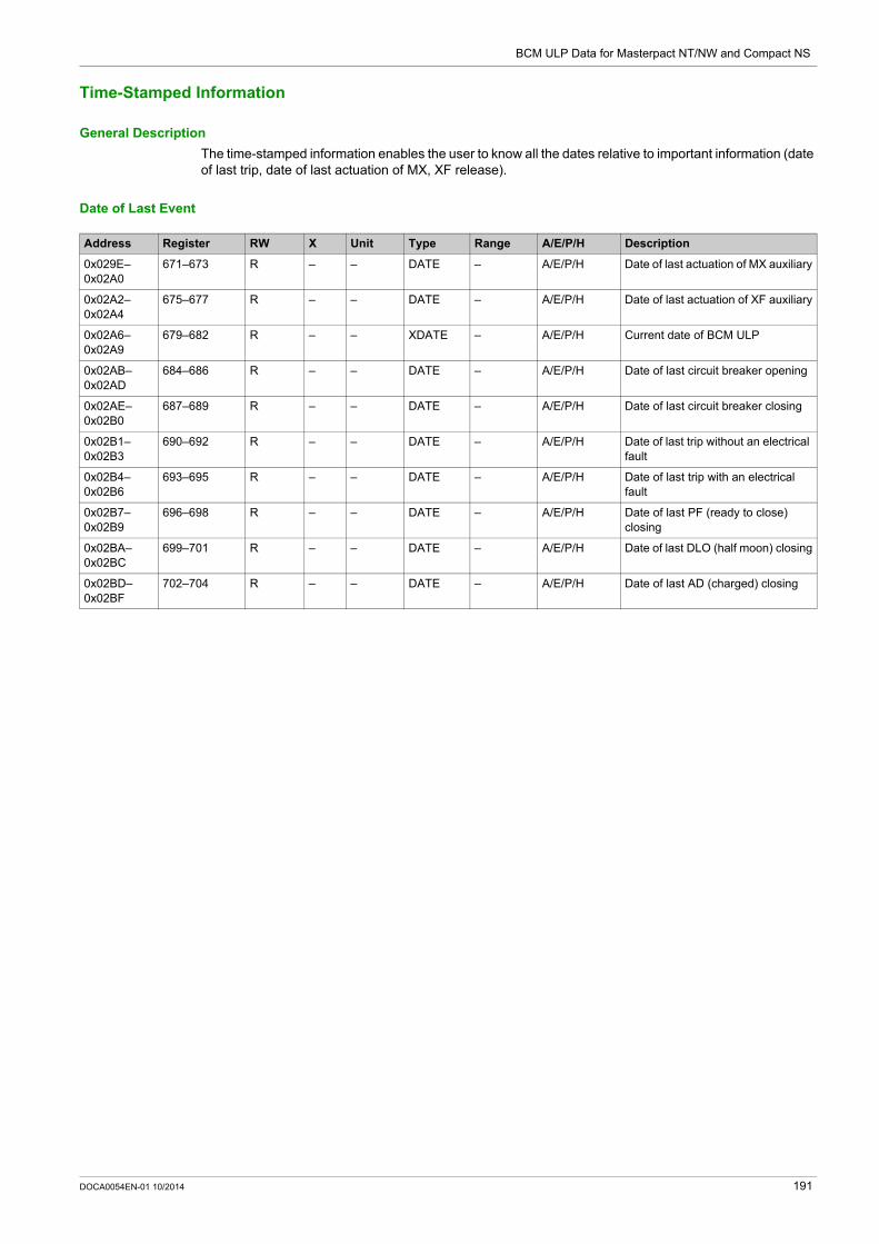
BCM ULP Data for Masterpact NT/NW and Compact NS
Time-Stamped Information
General Description
The time-stamped information enables the user to know all the dates relative to important information (date of last trip, date of last actuation of MX, XF release).
Date of Last Event
Address Register RW X Unit Type Range A/E/P/H Description
0x029E–0x02A0
671–673 R – – DATE – A/E/P/H Date of last actuation of MX auxiliary
0x02A2–0x02A4
675–677 R – – DATE – A/E/P/H Date of last actuation of XF auxiliary
0x02A6–0x02A9
679–682 R – – XDATE – A/E/P/H Current date of BCM ULP
0x02AB–0x02AD
684–686 R – – DATE – A/E/P/H Date of last circuit breaker opening
0x02AE–0x02B0
687–689 R – – DATE – A/E/P/H Date of last circuit breaker closing
0x02B1–0x02B3
690–692 R – – DATE – A/E/P/H Date of last trip without an electrical fault
0x02B4–0x02B6
693–695 R – – DATE – A/E/P/H Date of last trip with an electrical fault
0x02B7–0x02B9
696–698 R – – DATE – A/E/P/H Date of last PF (ready to close) closing
0x02BA–0x02BC
699–701 R – – DATE – A/E/P/H Date of last DLO (half moon) closing
0x02BD–0x02BF
702–704 R – – DATE – A/E/P/H Date of last AD (charged) closing
DOCA0054EN-01 10/2014 191

BCM ULP Data for Masterpact NT/NW and Compact NS
Counters
General Description
The BCM ULP has counters that help managing the circuit breaker.
The BCM ULP counters have the following properties: All the counters are saved in non-volatile memory to prevent data loss in case of power loss. The cumulating OF counter is read only. It stops incrementing when it reaches the maximum value of
65535. The user can preset all counters (except the cumulating OF counter) to any value from 0 to 65535. The
counters automatically cycle from 65535 to 0. A threshold is associated to the OF counter and to the close circuit breaker command counter.
The user can set the threshold to any value from 0 to 65534. The factory setting is 5000. An alarm is generated when a counter reaches the threshold.
BCM ULP Counters
Counter Thresholds
Circuit Breaker Operation Counters
MX and XF Release Counters
Address Register RW X Unit Type Range A/E/P/H Description
0x0229 554 R – – INT16U 0–65535 A/E/P/H Counter for the number of times the BCM ULP is energized
0x022A 555 R – – INT16U 0–65535 A/E/P/H Counter for the number of times the BCM ULP is reset whether following power loss or not
Address Register RW X Unit Type Range A/E/P/H Description
0x0243 580 RW – – INT16U 0–65535 A/E/P/H OF counter thresholdFactory setting = 5000
0x0244 581 RW – – INT16U 0–65535 A/E/P/H Close command counter thresholdFactory setting = 5000
Address Register RW X Unit Type Range A/E/P/H Description
0x0295 662 R – – INT16 0–65535 A/E/P/H Cumulating OF counter (non-resettable open to close counter)
0x0296 663 RW – – INT16 0–65535 A/E/P/H OF counter (resettable open to close counter)
0x0297 664 RW – – INT16 0–65535 A/E/P/H SD counter (close to SD position)
0x0298 665 RW – – INT16 0–65535 A/E/P/H SDE counter (close to SDE position)
Address Register RW X Unit Type Range A/E/P/H Description
0x02A1 674 R – – INT16U 0–65535 A/E/P/H MX actuation counter
0x02A5 678 R – – INT16U 0–65535 A/E/P/H XF actuation counter
192 DOCA0054EN-01 10/2014

BCM ULP Data for Masterpact NT/NW and Compact NS
Trip History
General Description
The trip history registers describe the last 17 encountered trips. The trip history format corresponds to a series of 17 records saved in a FIFO (first-in first-out) stack. The last record erases the oldest. Each record is composed of 7 registers describing one trip.
Trip Record Number
A read request of 7x(n) registers is necessary to read the last n trip records, where 7 is the number of registers for each trip record.
For example, a read request of 7x3 = 21 registers is necessary to read the last 3 trip records of the trip history: The first 7 registers describe the first trip record. The next 7 registers describe the second trip record. The last 7 registers describe the third trip record.
Trip Record
A read request of 7 registers is necessary to read a trip record.
The order and the description of the trip record registers are the same as that of the trip record 1:
Address Register Description
0x0095–0x009B 150–156 Trip record 0
0x009C–0x00A2 157–163 Trip record 1
0x00A3–0x00A9 164–170 Trip record 2
0x00AA–0x00B0 171–177 Trip record 3
0x00B1–0x00B7 178–184 Trip record 4
0x00B8–0x00BE 185–191 Trip record 5
0x00BF–0x00C5 192–198 Trip record 6
0x00C6–0x00CC 199–205 Trip record 7
0x00CD–0x00D3 206–212 Trip record 8
0x00D4–0x00DA 213–219 Trip record 9
0x00DB–0x00E1 220–226 Trip record 10
0x00E2–0x00E8 227–233 Trip record 11
0x00E9–0x00EF 234–240 Trip record 12
0x00F0–0x00F6 241–247 Trip record 13
0x00F7–0x00FD 248–254 Trip record 14
0x00FE–0x0104 255–261 Trip record 15
0x0105–0x010B 262–268 Trip record 16
Trip Record 1 (Most Recent Trip Record)
Address Register RW X Unit Type Range A/E/P/H Description
0x0095 150 R 1 – INT16U 0–65535 E/P/H Trip code
0x0096–0x0098
151–153 R 1 – ULP – E/P/H Date of event (trip or acknowledge)
0x0099 154 R 1 – INT16U 1–2 E/P/H Event typeMSB = 0 (reserved)Event occurrence: LSB = 1Event completion: LSB = 2
0x009A 155 – – – – – – Reserved
0x009B 156 – – – – – – Reserved
DOCA0054EN-01 10/2014 193

BCM ULP Data for Masterpact NT/NW and Compact NS
Trip Codes
Trip Code Description
1000 (0x03E8) Trip due to long-time protection Ir
1001 (0x03E9) Trip due to short-time protection Isd
1002 (0x03EA) Trip due to instantaneous protection Ii
1003 (0x03EB) Trip due to ground-fault protection Ig
1004 (0x03EC) Trip due to earth-leakage protection In
1005 (0x03ED) Trip due to integrated instantaneous protection I >>
1006–1007 (0x03EE–0x03EF) Reserved
1008 (0x03F0) Trip due to advanced protection
1009 (0x03F1) Trip due to extended advanced protection
1010–1015 (0x03F2–0x03F7) Reserved
1016 (0x3F8) Current unbalance
1017 (0x3F9) I1 maximum demand
1018 (0x3FA) I2 maximum demand
1019 (0x3FB) I3 maximum demand
1020 (0x3FC) IN maximum demand
1021 (0x3FD) Undervoltage
1022 (0x3FE) Overvoltage
1023 (0x3FF) Voltage unbalance
1024 (0x400) Reserved
1025 (0x401) Reverse power
1026 (0x402) Underfrequency
1027 (0x403) Overfrequency
1028 (0x404) Phase rotation
1029 (0x405) Current load shedding
1030 (0x406) Power load shedding
194 DOCA0054EN-01 10/2014

BCM ULP Data for Masterpact NT/NW and Compact NS
BCM ULP Files
Section 5.2BCM ULP Files
Circuit Breaker Manager Event Log
General Description
The system stores the events that concern circuit breaker control (for example opening or closing of the contacts) in the file number 30.
This file is made up of 100 records and each record is made up of 5 registers.
This file is reset in case of 24 Vdc power loss on the Breaker Communication Module or change of the communication parameter 4W/2W + ULP.
File Header
The following table describes the file header content:
File Status
The following table describes the file status content:
Event Record
The following table shows the format of 1 record in the event log of the circuit breaker:
Address Register RW X Unit Type Range A/E/P/H Description
0x02CD 718 R – – INT16U – A/E/P/H File status:0x0000 = file disabled0xFFFF = file enabled (factory setting)
0x02CE 719 R – – INT16U – A/E/P/H Type of file = 30
0x02CF 720 R – – INT16U – A/E/P/H File allocation = 0xFFFF
0x02D0 721 R 1 – INT16U – A/E/P/H Size of a record = 5 registers
0x02D1 722 R – – INT16U – A/E/P/H File filling mode:0 = circular
Address Register RW X Unit Type Range A/E/P/H Description
0x02DD 734 R 1 – INT16U 100 A/E/P/H Size of a file = 100 records
0x02DE 735 R 1 – INT16U 5 A/E/P/H Size of a record = 5 registers
0x02E0 737 R 1 – INT16U 0–100 A/E/P/H Number of records in the file
0x02E1 738 R 1 – INT16U 0–8000 A/E/P/H Sequence number of first record in the file (the oldest)
0x02E2 739 R 1 – INT16U 0–8000 A/E/P/H Sequence number of last record in the file (the most recent)
0x02E3– 0x02E5
740–742 R – – DATE – P/H Date of the last file resetFactory setting = 0x8000 0x8000 0x8000
Registers Type Description
1–4 XDATE Event date
5 INT16U Event number (see table below)
DOCA0054EN-01 10/2014 195
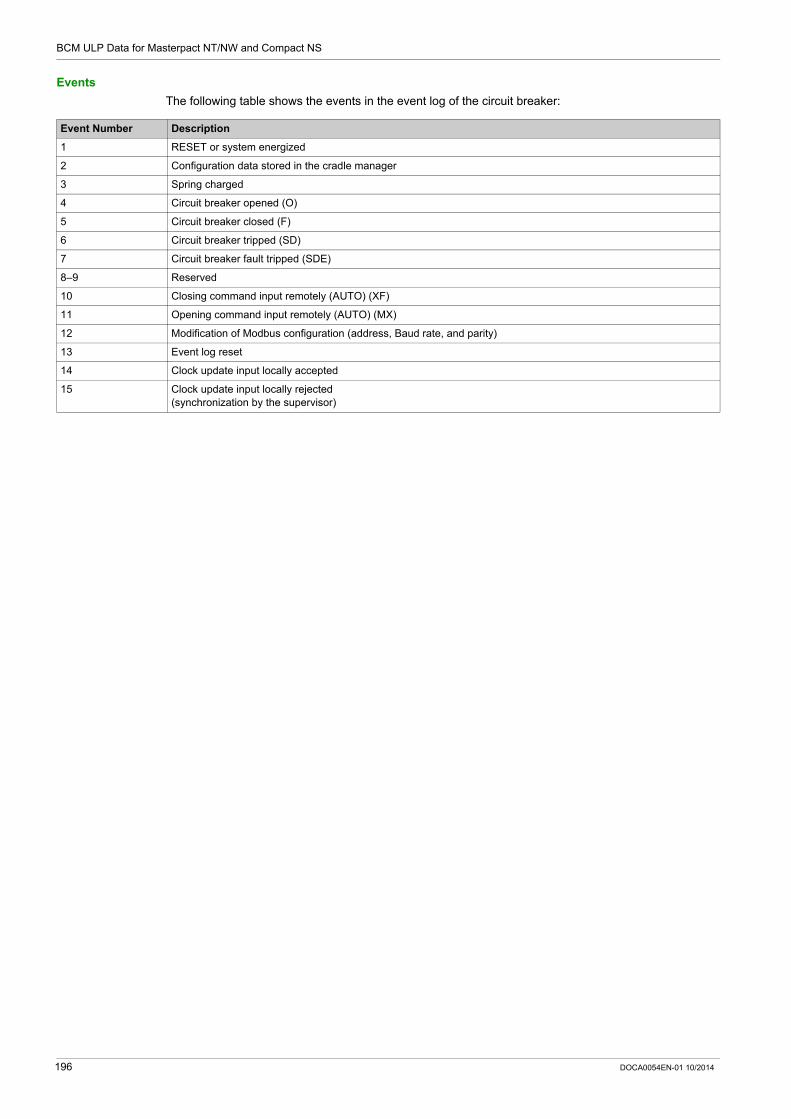
BCM ULP Data for Masterpact NT/NW and Compact NS
Events
The following table shows the events in the event log of the circuit breaker:
Event Number Description
1 RESET or system energized
2 Configuration data stored in the cradle manager
3 Spring charged
4 Circuit breaker opened (O)
5 Circuit breaker closed (F)
6 Circuit breaker tripped (SD)
7 Circuit breaker fault tripped (SDE)
8–9 Reserved
10 Closing command input remotely (AUTO) (XF)
11 Opening command input remotely (AUTO) (MX)
12 Modification of Modbus configuration (address, Baud rate, and parity)
13 Event log reset
14 Clock update input locally accepted
15 Clock update input locally rejected(synchronization by the supervisor)
196 DOCA0054EN-01 10/2014

BCM ULP Data for Masterpact NT/NW and Compact NS
BCM ULP Commands
Section 5.3BCM ULP Commands
What Is in This Section?
This section contains the following topics:
Topic Page
List of BCM ULP Commands and Error Codes 198
Circuit Breaker Control Commands 199
DOCA0054EN-01 10/2014 197

BCM ULP Data for Masterpact NT/NW and Compact NS
List of BCM ULP Commands and Error Codes
List of Commands
The following table lists the available BCM ULP commands, their corresponding command codes and password levels. Refer to the procedure to follow in order to write a command (see page 52).
Error Codes
In addition to generic error codes (see page 55), the BCM ULP commands generate the following error codes returned in register 8021:
Any other positive error code means an internal error.
Command Command Code Password Level
Open circuit breaker 904 Level 3 or 4
Close circuit breaker 905 Level 3 or 4
Enable/Inhibit close order 910 Level 3 or 4
Error Code Description
4759 (0x1297) Circuit breaker tripped. It must be reset before the command.
4760 (0x1298) Circuit breaker already closed.
4761 (0x1299) Circuit breaker already open.
4763 (0x129B) FDM121 in local control mode. Remote commands not allowed.
4766 (0x129E) Previous command still in progress.
4767 (0x12A0) Inhibit close order enabled.
4777 (0x12A9) Already in the asked state (valid only for enable/inhibit close order).
198 DOCA0054EN-01 10/2014

BCM ULP Data for Masterpact NT/NW and Compact NS
Circuit Breaker Control Commands
Open Circuit Breaker
To open the circuit breaker, the user must set up the command registers the following way:
Close Circuit Breaker
To close the circuit breaker, the user must set up the command registers the following way:
Enable/Inhibit a Circuit Breaker Close Order
To enable or inhibit a close order of the circuit breaker, the user must set up the command register the following way:
Address Register X Unit Type Range A/E/P/H Description
0x1F3F 8000 – – INT16U 904 A/E/P/H Command code = 904
0x1F40 8001 – – INT16U 10 A/E/P/H Number of parameters (bytes) = 10
0x1F41 8002 – – INT16U 4609 A/E/P/H Destination = 4609 (0x1201)
0x1F42 8003 – – INT16U 1 A/E/P/H 1
0x1F43–0x1F44
8004–8005
– – STRING – A/E/P/H Level 3 or 4 password For level 4, factory setting = ‘0000’ = 0x30303030 For level 3, factory setting = ‘3333’ = 0x33333333
Address Register X Unit Type Range A/E/P/H Description
0x1F3F 8000 – – INT16U 905 A/E/P/H Command code = 905
0x1F40 8001 – – INT16U 10 A/E/P/H Number of parameters (bytes) = 10
0x1F41 8002 – – INT16U 4609 A/E/P/H Destination = 4609 (0x1201)
0x1F42 8003 – – INT16U 1 A/E/P/H 1
0x1F43–0x1F44
8004–8005
– – STRING – A/E/P/H Level 3 or 4 password For level 4, factory setting =
‘0000’ = 0x30303030 For level 3, factory setting =
‘3333’ = 0x33333333
Address Register X Unit Type Range A/E/P/H Description
0x1F3F 8000 – – INT16U 910 A/E/P/H Command code = 910
0x1F40 8001 – – INT16U 13 A/E/P/H Number of parameters (bytes) = 13
0x1F41 8002 – – INT16U 4609 A/E/P/H Destination = 4609 (0x1201)
0x1F42 8003 – – INT16U 1 A/E/P/H 1
0x1F43–0x1F44
8004–8005
– – STRING – A/E/P/H Level 3 or level 4 password: For level 3, factory setting = ‘3333’
= 0x33333333 For level 4, factory setting = ‘0000’
= 0x30303030
0x1F45 8006 – – INT16U 1 A/E/P/H 0 = Enable close order 1 = Inhibit close order
0x1F46 8007 – – INT16U – A/E/P/H Origin of the command:256 = command sent via communication interface (IFM or IFE)
DOCA0054EN-01 10/2014 199

BCM ULP Data for Masterpact NT/NW and Compact NS
200 DOCA0054EN-01 10/2014

Masterpact NT/NW, Compact NS
IO Data for Masterpact NT/NW and Compact NS
DOCA0054EN-01 10/2014
IO Data for Masterpact NT/NW and Compact NS
Chapter 6IO Data for Masterpact NT/NW and Compact NS
What Is in This Chapter?
This chapter contains the following sections:
Section Topic Page
6.1 IO Registers 202
6.2 IO Events 218
6.3 IO Commands 225
DOCA0054EN-01 10/2014 201

IO Data for Masterpact NT/NW and Compact NS
IO Registers
Section 6.1IO Registers
Introduction
This section describes the IO registers.
Registers 13824 to 16823 are held by the IO 1.
Registers 16824 to 19710 are held by the IO 2: The registers of the parameters of IO 2 are equal to the registers of the parameters of IO 1 plus 3000.
Example: Register 14599 holds the digital input status register of the IO 1. Register 17599 holds the digital input status register of the IO 2.
The order of the registers is the same as that of the IO 1. The characteristics (access type, size, range, and unit) are the same as those of the registers of IO 1. Registers 15360 to 16109 containing the predefined application are specific to the IO 1 because they
hold the predefined applications.
What Is in This Section?
This section contains the following topics:
Topic Page
Analog Inputs 203
Digital Inputs 205
Digital Outputs 207
Hardware Setting 209
Digital Input and Output Status 210
IO Identification 211
Alarm Status 213
Applications 216
202 DOCA0054EN-01 10/2014

IO Data for Masterpact NT/NW and Compact NS
Analog Inputs
Analog Input Register Mapping
The following table describes the analog inputs and corresponding registers and addresses of the IO.
Analog Input Registers of IO 1
The order and the description of the analog input registers of IO 2 are the same as those of IO 1.
IO Analog Input Addresses Analog Input Registers
IO 1 0x35FF–0x3668 13824–13929
IO 2 0x41B7–0x4220 16824–16929
Address Register RW X Unit Type Range Description
0x35FF–0x3600
13824–13825
– – – – – Reserved
0x3601–0x3602
13826–13827
R 1 C FLOAT32 -50–250 Analog input sensor Pt100 temperature value (updated once every 1 s)
0x3603 13828 R 1 – INT16U – Data quality of the analog input0 = Valid1 = Invalid
0x3604 13829 – – – – – Reserved
0x3605–0x3608
13830–13833
R 1 – TI081 – Timestamp of the last change of +/- 1 C of the analog data value
0x3609–0x360C
13834–13837
– – – – – Reserved
0x360D–0x360E
13838–13839
RWC 1 C FLOAT32 -50–250 Analog input Pt100 maximum value
0x360F–0x3610
13840–13841
RWC 1 C FLOAT32 -50–250 Analog input Pt100 minimum value
0x3611–0x3614
13842–13845
RWC 1 – TI081 – Date and timestamp of the last minimum value recorded
0x3615–0x3618
13846–13849
RWC 1 – TI081 – Date and timestamp of the last maximum value recorded
0x3619–0x361C
13850–13853
RWC 1 – TI081 – Date and timestamp of the last reset for the minimum/maximum value
0x361D–0x361E
13854–13855
R 1 – INT32U 0–65534 Switchboard temperature threshold 1 counterThis counter increments every time threshold 1 is exceeded.
0x361F–0x3620
13856–13857
R 1 – INT32U 0–65534 Switchboard temperature threshold 2 counterThis counter increments every time threshold 2 is exceeded.
0x3621–0x3622
13858–13859
R 1 – INT32U 0–65534 Switchboard temperature threshold 3 counterThis counter increments every time threshold 3 is exceeded.
0x3623–0x363A
13860–13883
R 1 – STRING – Digital input identification coded over 45 ASCII characters (1)
0x363B 13884 R 1 – INT16U – Analog input type (1)0 = Analog input is not valid (factory setting)1 = not applicable2 = Pt100
0x363C 13885 – – – – – Reserved
0x363D–0x363E
13886–13887
R 1 C FLOAT32 -50–250 Switchboard temperature threshold 1 pick-up value (Pt100) (1)Factory setting = 50 C
0x363F–0x3640
13888–13889
R 1 s FLOAT32 1–3600 Switchboard temperature threshold 1 pick-up time delay (Pt100) (1)Factory setting = 10 s
(1) Value set using the customer engineering tool.
DOCA0054EN-01 10/2014 203

IO Data for Masterpact NT/NW and Compact NS
0x3641–0x3642
13890–13891
R 1 C FLOAT32 -50–250 Switchboard temperature threshold 1 drop-out value (Pt100) (1)Factory setting = 45 C
0x3643–0x3644
13892–13893
R 1 s FLOAT32 1–3600 Switchboard temperature threshold 1 drop-out time delay (Pt100) (1)Factory setting = 10 s
0x3645–0x3646
13894–13895
R 1 C FLOAT32 -50–250 Switchboard temperature threshold 2 pick-up value (Pt100) (1)Factory setting = 60 C
0x3647–0x3648
13896–13897
R 1 s FLOAT32 1–3600 Switchboard temperature threshold 2 pick-up time delay (Pt100) (1)Factory setting = 10 s
0x3649–0x364A
13898–13899
R 1 C FLOAT32 -50–250 Switchboard temperature threshold 2 drop-out value (Pt100) (1)Factory setting = 55 C
0x364B–0x364C
13900–13901
R 1 s FLOAT32 1–3600 Switchboard temperature threshold 2 drop-out time delay (Pt100) (1) Factory setting = 10 s
0x364D–0x364E
13902–13903
R 1 C FLOAT32 -50–250 Switchboard temperature threshold 3 pick-up value (Pt100) (1)Factory setting = 70 C
0x364F–0x3650
13904–13905
R 1 s FLOAT32 1–3600 Switchboard temperature threshold 3 pick-up time delay (Pt100) (1)Factory setting = 10 s
0x3651–0x3652
13906–13907
R 1 C FLOAT32 -50–250 Switchboard temperature threshold 3 drop-out value (Pt100) (1) Factory setting = 65 C
0x3653–0x3654
13908–13909
R 1 s FLOAT32 1–3600 Switchboard temperature threshold 3 drop-out time delay (Pt100) (1)Factory setting = 10 s
0x3655–0x3668
13910–13929
– – – – – Reserved
Address Register RW X Unit Type Range Description
(1) Value set using the customer engineering tool.
204 DOCA0054EN-01 10/2014

IO Data for Masterpact NT/NW and Compact NS
Digital Inputs
Digital Input Register Mapping
Each digital input description is made up of 80 registers.The order and the description of the digital inputs 2, 3, 4, 5, and 6 are the same as those of digital input 1.
Digital Input 1 Registers of IO 1
The order and the description of the digital input 1 registers of IO 2 are the same as those of IO 1:
IO Digital Input Number Digital Input Addresses Digital Input Registers
IO 1 I1 0x3669–0x36B8 13930–14009
I2 0x36B9–0x3708 14010–14089
I3 0x3709–0x3758 14090–14169
I4 0x3759–0x37A8 14170–14249
I5 0x37A9–0x37F8 14250–14329
I6 0x37F9–0x3848 14330–14409
IO 2 I1 0x4221–0x4270 16930–17009
I2 0x4271–0x42C0 17010–17089
I3 0x42C1–0x4310 17090–17169
I4 0x4311–0x4360 17170–17249
I5 0x4361–0x43B0 17250–17329
I6 0x43B1–0x4400 17330–17409
Address Register RW X Unit Type Range Description
0x3669 13930 R 1 – INT16U – Validity of each bit of the digital input status register:0 = Invalid1 = Valid
0x366A 13931 R 1 – INT16U – Digital input status:Bit 0 = 0: OFFBit 0 = 1: ONBit 1 = 0: UnforcedBit 1 = 1: Forced
0x366B–0x366E
13932–13935
R 1 – TI081 – Date and timestamp for the last input transition: Last rising edge if input is configured as NO
(normally open contact) Last falling edge if input is configured as NC
(normally closed contact)
Valid if input signal type is a normal digital input (not valid for pulse digital input).
0x366F 13936 R 1 – INT16U – Quality of the digital input status register0 = Valid1 = Invalid
0x3670 13937 – – – – – Reserved
0x3671–0x3672
13938–13939
RWC 1 – INT32U 0–4284867294 Input counter valueThis counter increments for each rising edge of the input.Valid if input signal type is normal digital input.
0x3673–0x3676
13940–13943
RWC 1 TI081 INT16U – Date and timestamp for the last input change counter preset/resetValid if input signal type is normal digital input.
0x3677–0x3678
13944–13945
RWC 1 – INT32U 0–4284867294 Number of pulses receivedValid if input signal type is pulse digital input.
(1) Value set by using the customer engineering tool.(2) Examples: If each incoming pulse represents 125 kWh, and since consumption data must be expressed in watt-hours, the consumption pulse weight
is 125,000. If each incoming pulse represents 1 US gallon, and since consumption data must be expressed in cubic meters, the consumption pulse
weight is 0.003785.
DOCA0054EN-01 10/2014 205
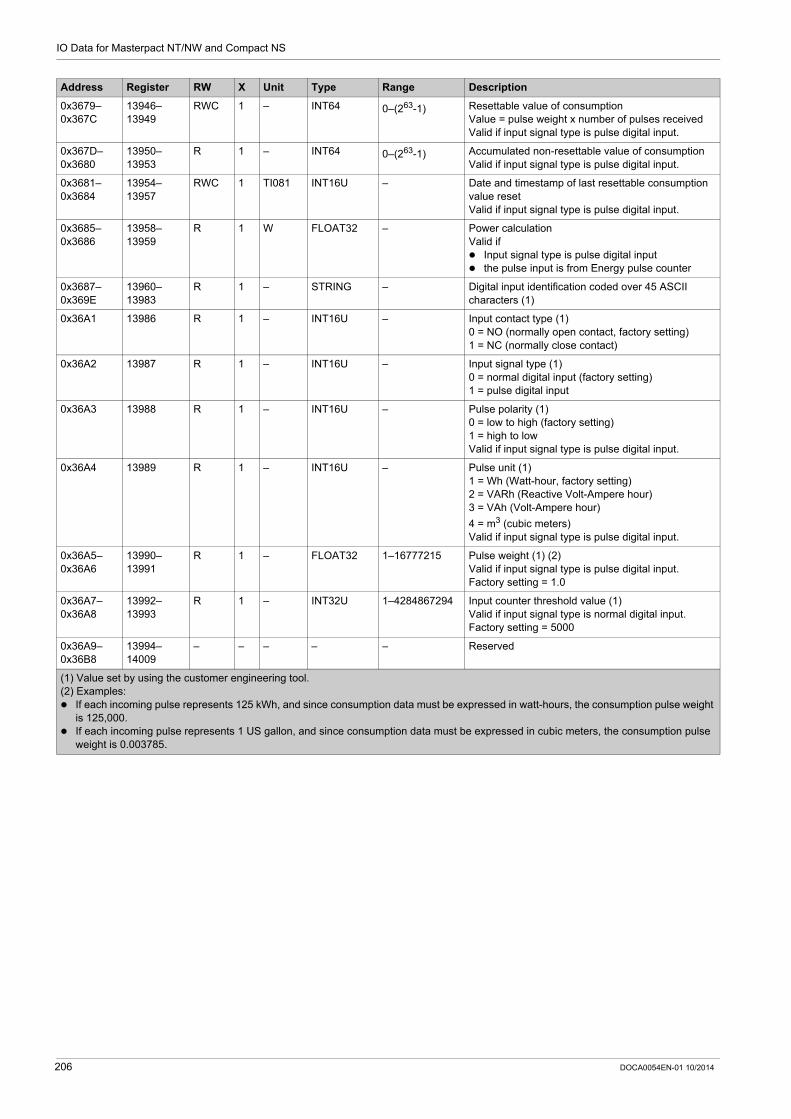
IO Data for Masterpact NT/NW and Compact NS
0x3679–0x367C
13946–13949
RWC 1 – INT64 0–(263-1) Resettable value of consumptionValue = pulse weight x number of pulses receivedValid if input signal type is pulse digital input.
0x367D–0x3680
13950–13953
R 1 – INT64 0–(263-1) Accumulated non-resettable value of consumptionValid if input signal type is pulse digital input.
0x3681–0x3684
13954–13957
RWC 1 TI081 INT16U – Date and timestamp of last resettable consumption value resetValid if input signal type is pulse digital input.
0x3685–0x3686
13958–13959
R 1 W FLOAT32 – Power calculationValid if Input signal type is pulse digital input the pulse input is from Energy pulse counter
0x3687–0x369E
13960–13983
R 1 – STRING – Digital input identification coded over 45 ASCII characters (1)
0x36A1 13986 R 1 – INT16U – Input contact type (1)0 = NO (normally open contact, factory setting)1 = NC (normally close contact)
0x36A2 13987 R 1 – INT16U – Input signal type (1)0 = normal digital input (factory setting)1 = pulse digital input
0x36A3 13988 R 1 – INT16U – Pulse polarity (1)0 = low to high (factory setting)1 = high to lowValid if input signal type is pulse digital input.
0x36A4 13989 R 1 – INT16U – Pulse unit (1)1 = Wh (Watt-hour, factory setting)2 = VARh (Reactive Volt-Ampere hour)3 = VAh (Volt-Ampere hour)
4 = m3 (cubic meters)Valid if input signal type is pulse digital input.
0x36A5–0x36A6
13990–13991
R 1 – FLOAT32 1–16777215 Pulse weight (1) (2)Valid if input signal type is pulse digital input.Factory setting = 1.0
0x36A7–0x36A8
13992–13993
R 1 – INT32U 1–4284867294 Input counter threshold value (1)Valid if input signal type is normal digital input.Factory setting = 5000
0x36A9–0x36B8
13994–14009
– – – – – Reserved
Address Register RW X Unit Type Range Description
(1) Value set by using the customer engineering tool.(2) Examples: If each incoming pulse represents 125 kWh, and since consumption data must be expressed in watt-hours, the consumption pulse weight
is 125,000. If each incoming pulse represents 1 US gallon, and since consumption data must be expressed in cubic meters, the consumption pulse
weight is 0.003785.
206 DOCA0054EN-01 10/2014

IO Data for Masterpact NT/NW and Compact NS
Digital Outputs
Digital Output Register Mapping
Each digital output description is made up of 60 registers. The order and the description of the digital outputs 2 and 3 are the same as those of digital output 1.
IO Digital Output Number Digital Output Addresses Digital Output Registers
IO 1 O1 0x3849–0x3884 14410–14469
O2 0x3885–0x38C0 14470–14529
O3 0x38C1–0x38FC 14530–14589
IO 2 O1 0x4401–0x443C 17410–17469
O2 0x443D–0x4478 17470–17529
O3 0x4479–0x44B4 17530–17589
DOCA0054EN-01 10/2014 207

IO Data for Masterpact NT/NW and Compact NS
Digital Output 1 Registers of IO 1
The order and the description of the digital output 1 registers of IO 2 are the same as those of IO 1:
Address Register RW X Unit Type Range Description
0x3849 14410 R 1 – INT16U – Digital output status validity0 = Invalid1 = Valid
0x384A 14411 R 1 – INT16U – Digital output statusBit 0 = 0: OFFBit 0 = 1: ONBit 1 = 0: UnforcedBit 1 = 1: Forced
0x384B–0x384E
14412–14415
R 1 TI081 INT16U – Date and timestamp for the last output transition: Last rising edge if output is configured as NO
(normally open contact) Last falling edge if output is configured as NC
(normally closed contact)
0x384F 14416 R 1 – INT16U – Quality of the digital output status register0 = Valid1 = Invalid
0x3850 14417 – – – – – Reserved
0x3851–0x3852
14418–14419
RWC 1 – INT32U 0–4284867294 Output counter This counter increments for each rising edge of the output.
0x3853–0x3856
14420–14423
R 1 TI081 INT16U – Date and time stamp of the last reset for the output counter
0x3857–0x386E
14424–14447
RWC 1 – INT32U – Digital output identification coded over 45 ASCII characters
0x386F 14448 R 1 – INT16U – Output operating mode (1)0 = Non-latching (factory setting)1 = Latched2 = Time delayed non-latching
0x3870 14449 R 1 s INT16U 0–65534 On time for time delayed non-latching mode value (1)The time for the output to remain energized when the output is in time delayed non-latching mode(Factory setting = 0)
0x3871 14450 R 1 – INT16U – Output contact type (1)0 = NO (normally open, factory setting)1 = NC (normally close)
0x3872 14451 R 1 – INT16U – Indicates On/Off state of the discrete output when any fall back condition occurs (1):0 = OFF (factory setting)1 = ON2 = Freeze
0x3873–0x3874
14452–14453
R 1 – INT32U 1–4284867294 Output counter threshold value (1)Factory setting = 5000
0x3875 14454 RW 1 – INT16U – Simple command for output (2):0 = No command1 = OFF2 = ONValid if simple commands are enabled.
0x3876–0x3884
14455–14469
– – – – – Reserved
(1) Value set using the customer engineering tool.(2) Simple commands are enabled by factory setting. The simple commands can be disabled by using the command Enable/Disable simple commands (see page 228).
208 DOCA0054EN-01 10/2014

IO Data for Masterpact NT/NW and Compact NS
Hardware Setting
Addresses and Registers List
The following table describes the hardware settings addresses, and registers regarding the IO.
Hardware Setting Registers for IO 1
The order and the description of the hardware setting registers for IO 2 are the same as those of IO 1.
IO Addresses Registers
IO 1 0x38FD–0x3902 14590–14595
IO 2 0x44B5–0x44BA 17590–17595
Address Register RW X Unit Type Range Description
0x38FD 14590 R 1 – INT16U 1–9 Application rotary switch current position:1 = position 12 = position 23 = position 34 = position 45 = position 56 = position 67 = position 78 = position 89 = position 9
0x38FE 14591 R 1 – INT16U 0–1 Remote setup padlock position:0 = Unlock1 = Lock
0x38FF 14592 R 1 – INT16U 0–1 Dip switch1 position:0 = IO 11 = IO 2
0x3900 14593 – – – – – Reserved
0x3901 14594 R 1 – INT16U 1–9 Last validated application set by the test button located on the front of the IO:1 = position 12 = position 23 = position 34 = position 45 = position 56 = position 67 = position 78 = position 89 = position 9
0x3902 14595 R 1 – INT16U 1–9 Last validated application set by the customer engineering tool:1 = position 12 = position 23 = position 34 = position 45 = position 56 = position 67 = position 78 = position 89 = position 9
0x3903–0x3904
14596–14597
– – – – – Reserved
DOCA0054EN-01 10/2014 209

IO Data for Masterpact NT/NW and Compact NS
Digital Input and Output Status
Addresses and Registers List
The following table describes the digital inputs and outputs status addresses, and registers regarding the IO.
Digital Input and Output Status Registers for IO 1
The order and the description of the digital input and output status registers for IO 2 are the same as those of IO 1.
IO Addresses Registers
IO 1 0x3905–0x3908 14598–14601
IO 2 0x44BD–0x44C0 17598–17601
Address Register RW X Unit Type Range Bit Description
0x3905 14598 R 1 – INT16U – – Validity of each bit of the digital input status register:0 = Invalid1 = Valid
0x3906 14599 R 1 – INT16U – – Digital input status register:Input status = 0 when input is OFFInput status = 1 when input is ON
0 I1 status
1 I2 status
2 I3 status
3 I4 status
4 I5 status
5 I6 status
0x3907 14600 R 1 – INT16U – – Validity of each bit of the digital output status register:0 = Invalid1 = Valid
0x3908 14601 R 1 – INT16U – – Digital output status register:Output status = 0 when output is OFFOutput status = 1 when output is ON
0 O1 status
1 O2 status
2 O3 status
210 DOCA0054EN-01 10/2014
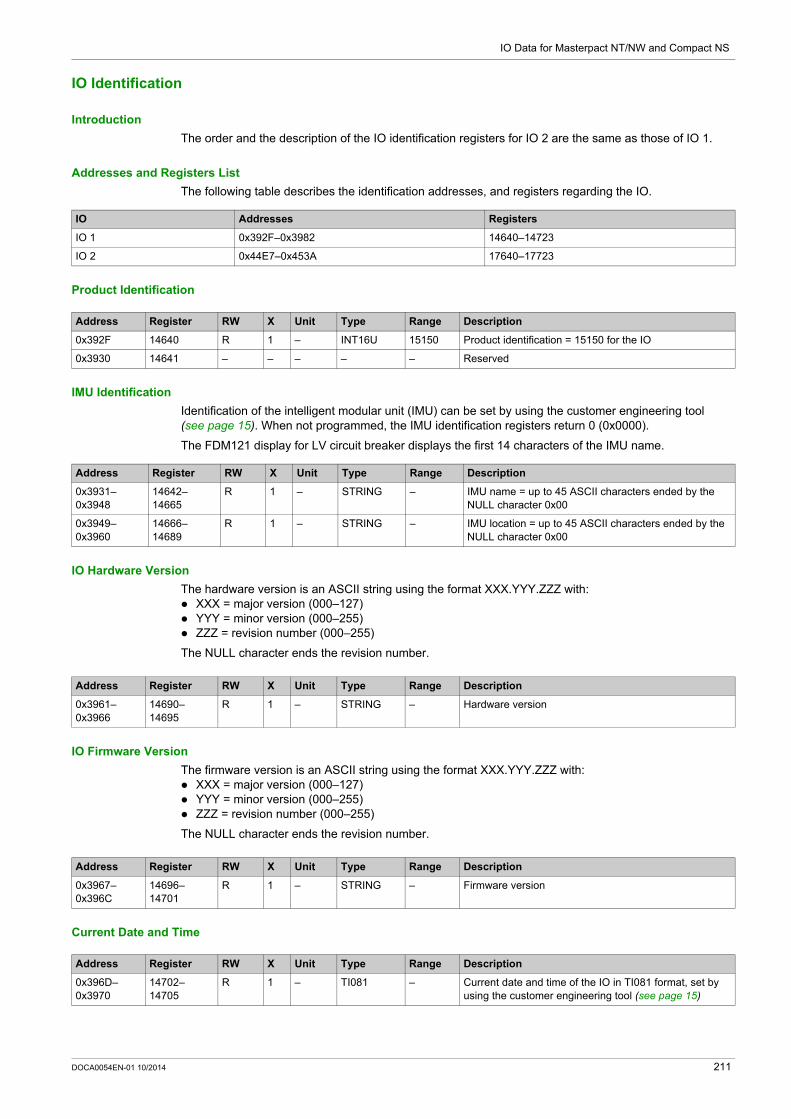
IO Data for Masterpact NT/NW and Compact NS
IO Identification
Introduction
The order and the description of the IO identification registers for IO 2 are the same as those of IO 1.
Addresses and Registers List
The following table describes the identification addresses, and registers regarding the IO.
Product Identification
IMU Identification
Identification of the intelligent modular unit (IMU) can be set by using the customer engineering tool (see page 15). When not programmed, the IMU identification registers return 0 (0x0000).
The FDM121 display for LV circuit breaker displays the first 14 characters of the IMU name.
IO Hardware Version
The hardware version is an ASCII string using the format XXX.YYY.ZZZ with: XXX = major version (000–127) YYY = minor version (000–255) ZZZ = revision number (000–255)
The NULL character ends the revision number.
IO Firmware Version
The firmware version is an ASCII string using the format XXX.YYY.ZZZ with: XXX = major version (000–127) YYY = minor version (000–255) ZZZ = revision number (000–255)
The NULL character ends the revision number.
Current Date and Time
IO Addresses Registers
IO 1 0x392F–0x3982 14640–14723
IO 2 0x44E7–0x453A 17640–17723
Address Register RW X Unit Type Range Description
0x392F 14640 R 1 – INT16U 15150 Product identification = 15150 for the IO
0x3930 14641 – – – – – Reserved
Address Register RW X Unit Type Range Description
0x3931–0x3948
14642–14665
R 1 – STRING – IMU name = up to 45 ASCII characters ended by the NULL character 0x00
0x3949–0x3960
14666–14689
R 1 – STRING – IMU location = up to 45 ASCII characters ended by the NULL character 0x00
Address Register RW X Unit Type Range Description
0x3961–0x3966
14690–14695
R 1 – STRING – Hardware version
Address Register RW X Unit Type Range Description
0x3967–0x396C
14696–14701
R 1 – STRING – Firmware version
Address Register RW X Unit Type Range Description
0x396D–0x3970
14702–14705
R 1 – TI081 – Current date and time of the IO in TI081 format, set by using the customer engineering tool (see page 15)
DOCA0054EN-01 10/2014 211

IO Data for Masterpact NT/NW and Compact NS
Serial Number
The IO serial number is composed of a maximum of 11 alphanumeric characters with the following format: PPYYWWDnnnn. PP = plant code YY = year of fabrication (05–99) WW = week of fabrication (01–53) D = day of fabrication (1–7) nnnn = sequence number (0001–9999)
A read request of 6 registers is necessary to read the IO serial number.
Manufacturing Date and Time
Product Identification
Address Register RW X Unit Type Range Description
(0x03971) 14706 R – – STRING – ‘PP’
(0x03972) 14707 R – – STRING ‘05’–‘99’ ‘YY’
(0x03973) 14708 R – – STRING ‘01’–‘53’ ‘WW’
(0x03974) 14709 R – – STRING ‘10’–‘79’ ‘Dn’
(0x03975) 14710 R – – STRING ‘00’–‘99’ ‘nn’
(0x03976) 14711 R – – STRING ‘0’–‘9’ ‘n’ (the NULL character ends the serial number)
Address Register RW X Unit Type Range Description
0x397B–0x397E
14716–14719
R 1 – TI081 – Manufacturing date and time
Address Register RW X Unit Type Range Description
0x397F–0x3982
14720–14723
R 1 – STRING – Commercial reference of the IO = LV434063
212 DOCA0054EN-01 10/2014

IO Data for Masterpact NT/NW and Compact NS
Alarm Status
Addresses and Registers List
The following table describes the alarm status addresses, and registers regarding the IO.
Generic Alarm Status for IO 1
The order and the description of the generic alarm status registers for IO 2 are the same as those of IO 1.
IO Addresses Registers
IO 1 0x3989–0x39A6 14730–14759
IO 2 0x4541–0x455E 17730–17759
Address Register RW X Unit Type Range Bit Description
0x3989 14730 R 1 – INT16U – – Validity of each bit of the IO history format register:0 = Invalid1 = Valid
0x398A 14731 R 1 – INT16U – – IO history format register
0 Bit 0 = 1: ULP history format (factory setting)
1 Bit 1 = 1: TI086 history format
0x398B 14732 R 1 – INT16U – – Validity of each bit of the IO command type register:0 = Invalid1 = Valid
0x398C 14733 R 1 – INT16U – – IO command typeFactory setting = 3, both write command mechanisms are enabled.
0 Bit 0 = 1: write commands using the command interface
1 Bit 1 = 0: write commands using Modbus is disabled.Bit 1 = 1: write commands using Modbus is enabled.
0x398D–0x3992
14734–14739
– – – – – – Reserved
0x3993 14740 R 1 – INT16U – – Validity of each bit of the IO generic alarm 1 register:0 = Invalid1 = Valid
0x3994 14741 R 1 – INT16U – – IO generic alarm 1 status register.
0 IO in STOP mode: IO is not working and must be replaced.
1 IO in ERROR mode: IO is working in degraded mode.
2 Threshold overrun on I1 counter
3 Threshold overrun on I2 counter
4 Threshold overrun on I3 counter
5 Threshold overrun on I4 counter
6 Threshold overrun on I5 counter
7 Threshold overrun on I6 counter
8 Threshold overrun on O1 counter
9 Threshold overrun on O2 counter
10 Threshold overrun on O3 counter
11 Switchboard temperature threshold 1 overrun
12 Switchboard temperature threshold 2 overrun
13 Switchboard temperature threshold 3 overrun
14–15 Reserved
0x3995 14742 R 1 – INT16U – – Validity of each bit of the IO generic alarm 2 register:0 = Invalid1 = Valid
DOCA0054EN-01 10/2014 213

IO Data for Masterpact NT/NW and Compact NS
Cradle and Drawer Management Alarms for IO 1
0x3996 14743 R 1 – INT16U – – IO generic alarm 2 status register.
0 User-defined input 1 alarm
1 User-defined input 2 alarm
2 User-defined input 3 alarm
3 User-defined input 4 alarm
4 User-defined input 5 alarm
5 User-defined input 6 alarm
6–15 Reserved
Address Register RW X Unit Type Range Bit Description
Address Register RW X Unit Type Range Bit Description
0x3997 14744 R 1 – INT16U – – Validity of each bit of the cradle management alarms register.0 = Invalid1 = Valid
0x3998 14745 R 1 – INT16U – – Cradle management alarms register
0 Cradle position discrepancy
1 Remove device from cradle and put it back
2 Design life of the cradleReplacement of the cradle has to be performed within 6 months
3 Regrease cradle and disconnecting contact clusters to be performed by qualified maintenance staff
4 New Micrologic trip unit has been detected
5–7 Reserved
8 Drawer position discrepancy
9–15 Reserved
0x3999–0x399A
14746–14747
– – – – – – Reserved
214 DOCA0054EN-01 10/2014

IO Data for Masterpact NT/NW and Compact NS
Miscellaneous Application Alarms for IO 1
Address Register RW X Unit Type Range Bit Description
0x399B 14748 R 1 – INT16U – – Validity of each bit of the other application alarms register.0 = Invalid1 = Valid
0x399C 14749 R 1 – INT16U – – Other application alarms register
0 Auxiliary contact of load contactor 1 is not closed.
1 Auxiliary contact of load contactor 1 is not opened.
2–15 Reserved
0x399D 14750 R 1 – INT16U – – Validity of each bit of the predefined input alarms register:0 = Invalid1 = Valid
0x399E 14751 R 1 – INT16U – – Predefined input alarms register
0 Earth-leakage trip signal contact (SDV)
1 Control voltage presence contact
2 Surge protection status contact
3 Surge failure contact
4 Switch-disconnector ON/OFF indication contact (OF)
5 Fuse blown indication contact
6 Emergency stop
7 Switchboard temperature contact
8 Switchboard ventilation contact
9 Switchboard door contact
10–15 Reserved
0x399F 14752 R 1 – INT16U – – Validity of each bit of the IO discrepancy alarms register:0 = Invalid1 = Valid
0x39A0 14753 R 1 – INT16U – – IO discrepancy alarms register
0 Critical hardware discrepancy
1 Critical firmware discrepancy
2 Non-critical hardware discrepancy
3 Non-critical firmware discrepancy
4–15 Reserved
0x39A1–0x39A6
14754–14759
– – – – – – Reserved
DOCA0054EN-01 10/2014 215
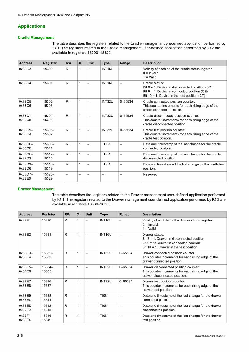
IO Data for Masterpact NT/NW and Compact NS
Applications
Cradle Management
The table describes the registers related to the Cradle management predefined application performed by IO 1. The registers related to the Cradle management user-defined application performed by IO 2 are available in registers 18300–18329.
Drawer Management
The table describes the registers related to the Drawer management user-defined application performed by IO 1. The registers related to the Drawer management user-defined application performed by IO 2 are available in registers 18330–18359.
Address Register RW X Unit Type Range Description
0x3BC3 15300 R 1 – INT16U – Validity of each bit of the cradle status register:0 = Invalid1 = Valid
0x3BC4 15301 R 1 – INT16U – Cradle status:Bit 8 = 1: Device in disconnected position (CD)Bit 9 = 1: Device in connected position (CE)Bit 10 = 1: Device in the test position (CT)
0x3BC5–0x3BC6
15302–15303
R 1 – INT32U 0–65534 Cradle connected position counter:This counter increments for each rising edge of the cradle connected position.
0x3BC7–0x3BC8
15304–15305
R 1 – INT32U 0–65534 Cradle disconnected position counter:This counter increments for each rising edge of the cradle disconnected position.
0x3BC9–0x3BCA
15306–15307
R 1 – INT32U 0–65534 Cradle test position counter:This counter increments for each rising edge of the cradle test position.
0x3BCB–0x3BCE
15308–15311
R 1 – TI081 – Date and timestamp of the last change for the cradle connected position.
0x3BCF–0x3BD2
15312–15315
R 1 – TI081 – Date and timestamp of the last change for the cradle disconnected position.
0x3BD3–0x3BD6
15316–15319
R 1 – TI081 – Date and timestamp of the last change for the cradle test position.
0x3BD7–0x3BE0
15320–15329
– – – – – Reserved
Address Register RW X Unit Type Range Description
0x3BE1 15330 R 1 – INT16U – Validity of each bit of the drawer status register:0 = Invalid1 = Valid
0x3BE2 15331 R 1 – INT16U – Drawer status:Bit 8 = 1: Drawer in disconnected positionBit 9 = 1: Drawer in connected positionBit 10 = 1: Drawer in the test position
0x3BE3–0x3BE4
15332–15333
R 1 – INT32U 0–65534 Drawer connected position counter:This counter increments for each rising edge of the drawer connected position.
0x3BE5–0x3BE6
15334–15335
R 1 – INT32U 0–65534 Drawer disconnected position counter:This counter increments for each rising edge of the drawer disconnected position.
0x3BE7–0x3BE8
15336–15337
R 1 – INT32U 0–65534 Drawer test position counter:This counter increments for each rising edge of the drawer test position.
0x3BE9–0x3BEC
15338–15341
R 1 – TI081 – Date and timestamp of the last change for the drawer connected position.
0x3BED–0x3BF0
15342–15345
R 1 – TI081 – Date and timestamp of the last change for the drawer disconnected position.
0x3BF1–0x3BF4
15346–15349
R 1 – TI081 – Date and timestamp of the last change for the drawer test position.
216 DOCA0054EN-01 10/2014

IO Data for Masterpact NT/NW and Compact NS
Light Control
The table describes the registers related to the Light control predefined application performed by IO 1.
Load Control
The table describes the registers related to the Load control predefined application performed by IO 1.
0x3BF5–0x3BFE
15350–15359
– – – – – Reserved
Address Register RW X Unit Type Range Description
Address Register RW X Unit Type Range Description
0x3C27 15400 R 1 – INT16U 0–1 Validity of each bit of the light status register:0 = Invalid1 = Valid (application is configured and running)
0x3C28 15401 R 1 – INT16U 0–1 Light status:0 = Reset/OFF1 = Set/ON
0x3C29–0x3C2A
15402–15403
R 1 s INT32U 0–54000 Remaining time in ON or OFF state (depending of the light status)
0x3C2B– 15404 RW 1 – INT16U 0–2 Light simple command (1):0 = No command1 = Light OFF2 = Light ON
0x3C2C–0x3C30
15405–15409
– – – – – Reserved
(1) Simple commands are enabled by factory setting. The simple commands can be disabled by using the command Enabled/Disable simple commands (see page 228).
Address Register RW X Unit Type Range Description
0x3C31 15410 R 1 – INT16U 0–1 Validity of each bit of the load status register:0 = Invalid1 = Valid (application is configured and running)
0x3C32 15411 R 1 – INT16U 0–1 Load status:0 = Reset/OFF1 = Set/ON
0x3C33–0x3C34
15412–15413
R 1 s INT32U 0–54000 Remaining time in ON or OFF state (depending of the load status)
0x3C35 15414 RW 1 – INT16U 0–2 Load simple command (1):0 = No command1 = Load OFF2 = Load ON
0x3C36–0x3EEC
15415–16109
– – – – – Reserved
(1) Simple commands are enabled by factory setting. The simple commands can be disabled by using the command Enabled/Disable simple commands (see page 228).
DOCA0054EN-01 10/2014 217

IO Data for Masterpact NT/NW and Compact NS
IO Events
Section 6.2IO Events
What Is in This Section?
This section contains the following topics:
Topic Page
Event History 219
IO Events and Alarms 220
218 DOCA0054EN-01 10/2014

IO Data for Masterpact NT/NW and Compact NS
Event History
General Description
The event history registers describe the last 100 encountered events. The event history format corresponds to a series of 100 records. Each record is composed of 5 registers describing one event.
A read request of 5x(n) registers is necessary to read the last n event records, where 5 is the number of registers for each event record.
For example, a read request of 5x3 = 15 registers is necessary to read the last 3 event records of the event history: The first 5 registers describe the first event record (most recent event). The next 5 registers describe the second event record. The last 5 registers describe the third event record.
There are 2 event histories, 1 per IO.
Event Record
A block request of 5 registers is necessary to read an event record.The order and the description of the event record registers of IO 2 are the same as those of IO 1:
Alarm Definition
Alarms are specific events that need to be reset.
The reset mode of an alarm can be: automatic: the alarm is reset automatically when the alarm is no more active. manual: the alarm is reset manually with the Test/Reset push button located on the front face of the IO
and when the alarm is no more active. remote: the alarm is reset remotely with the Reset command sent via the communication and when the
alarm is no more active.
Each alarm has a priority level that manages the alarm display on the FDM121 display for LV circuit breaker: no priority = N/A (not affected) low priority = 1. No alarm display on the FDM121 medium priority = 2. The FDM121 LED is steady ON. high priority = 3. The FDM121 LED blinks and a pop-up screen informs the user that the alarm has
occurred.
IO Address Register Description
IO 1 0x39A7–0x39AB 14760–14764 Event record 1 (most recent event record)
0x39AC–0x39B0 14765–14769 Event record 2
0x39A7+5x(n-1)–0x39AB+5x(n-1) 14760+5x(n-1)–14764+5x(n-1) Event record n
0x3B96–0x3B9A 15255–15259 Event record 100
IO 2 0x455F–0x4563 17760–17764 Event record 1 (most recent event record)
0x4564–0x4568 17765–17769 Event record 2
0x455F+5x(n-1)–0x4563+5x(n-1) 17760+5x(n-1)–17764+5x(n-1) Event record n
0x474E–0x4752 18255–18259 Event record 100
Event Record 1 (Most Recent Event Record)
Register Address RW Type Description
0x39A7 14760 R INT16U Event code of IO 1 and IO 2 (see page 220)
0x39A8–0x39AA
14761–14763
R ULP Date and time of the event (see page 62).
0x39AB 14764 R INT16U Event typeMSB = 0 (reserved)Event occurrence: LSB = 1Event completion: LSB = 2
DOCA0054EN-01 10/2014 219
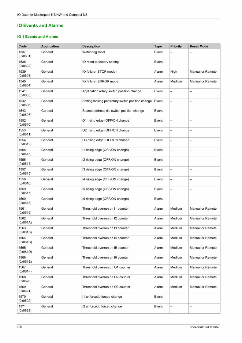
IO Data for Masterpact NT/NW and Compact NS
IO Events and Alarms
IO 1 Events and Alarms
Code Application Description Type Priority Reset Mode
1537 (0x0601)
General Watchdog reset Event – –
1538 (0x0602)
General IO reset to factory setting Event – –
1539 (0x0603)
General IO failure (STOP mode) Alarm High Manual or Remote
1540 (0x0604)
General IO failure (ERROR mode) Alarm Medium Manual or Remote
1541 (0x0605)
General Application rotary switch position change Event – –
1542 (0x0606)
General Setting locking pad rotary switch position change Event – –
1543 (0x0607)
General Source address dip switch position change Event – –
1552 (0x0610)
General O1 rising edge (OFF/ON change) Event – –
1553 (0x0611)
General O2 rising edge (OFF/ON change) Event – –
1554 (0x0612)
General O3 rising edge (OFF/ON change) Event – –
1555 (0x0613)
General I1 rising edge (OFF/ON change) Event – –
1556 (0x0614)
General I2 rising edge (OFF/ON change) Event – –
1557 (0x0615)
General I3 rising edge (OFF/ON change) Event – –
1558 (0x0616)
General I4 rising edge (OFF/ON change) Event – –
1559 (0x0617)
General I5 rising edge (OFF/ON change) Event – –
1560 (0x0618)
General I6 rising edge (OFF/ON change) Event – –
1561 (0x0619)
General Threshold overrun on I1 counter Alarm Medium Manual or Remote
1562 (0x061A)
General Threshold overrun on I2 counter Alarm Medium Manual or Remote
1563 (0x061B)
General Threshold overrun on I3 counter Alarm Medium Manual or Remote
1564 (0x061C)
General Threshold overrun on I4 counter Alarm Medium Manual or Remote
1565 (0x061D)
General Threshold overrun on I5 counter Alarm Medium Manual or Remote
1566 (0x061E)
General Threshold overrun on I6 counter Alarm Medium Manual or Remote
1567 (0x061F)
General Threshold overrun on O1 counter Alarm Medium Manual or Remote
1568 (0x0620)
General Threshold overrun on O2 counter Alarm Medium Manual or Remote
1569 (0x0621)
General Threshold overrun on O3 counter Alarm Medium Manual or Remote
1570 (0x0622)
General I1 unforced / forced change Event – –
1571 (0x0623)
General I2 unforced / forced change Event – –
220 DOCA0054EN-01 10/2014

IO Data for Masterpact NT/NW and Compact NS
1572 (0x0624)
General I3 unforced / forced change Event – –
1573 (0x0625)
General I4 unforced / forced change Event – –
1574 (0x0626)
General I5 unforced / forced change Event – –
1575 (0x0627)
General I6 unforced / forced change Event – –
1576 (0x0628)
General O1 unforced / forced change Event – –
1577 (0x0629)
General O2 unforced / forced change Event – –
1578 (0x062A)
General O3 unforced / forced change Event – –
1579 (0x062B)
User-defined input acquisition
User-defined input 1 Alarm Medium Manual or Remote
1580 (0x062C)
User-defined input acquisition
User-defined input 2 Alarm Medium Manual or Remote
1581 (0x062D)
User-defined input acquisition
User-defined input 3 Alarm Medium Manual or Remote
1582 (0x062E)
User-defined input acquisition
User-defined input 4 Alarm Medium Manual or Remote
1583 (0x062F)
User-defined input acquisition
User-defined input 5 Alarm Medium Manual or Remote
1584 (0x0630)
User-defined input acquisition
User-defined input 6 Alarm Medium Manual or Remote
1585 (0x0631)
Cooling system Switchboard temperature threshold 1 overrun Alarm Low Auto
1586 (0x0632)
Cooling system Switchboard temperature threshold 2 overrun Alarm Medium Manual or Remote
1587 (0x0633)
Cooling system Switchboard temperature threshold 3 overrun Alarm High Manual or Remote
2304 (0x0900)
Cradle management Cradle position discrepancy Alarm Medium Manual or Remote
2305 (0x0901)
Cradle management Cradle connected contact change Event – –
2306 (0x0902)
Cradle management Cradle disconnected contact change Event – –
2307 (0x0903)
Cradle management Cradle test contact change Event – –
2308 (0x0904)
Cradle management Remove device from cradle and put it back Alarm Medium Manual or Remote
2309 (0x0905)
Cradle management Design life of the cradleReplacement of the cradle has to be performed within 6 months.
Alarm High Manual or Remote
2310 (0x0906)
Cradle management Regrease cradle and disconnecting-contact clusters to be performed by qualified maintenance staff
Alarm Medium Manual or Remote
2311 (0x0907)
Cradle management New Micrologic trip unit has been detected. Alarm High Manual or Remote
2432 (0x0980)
Drawer management Drawer position discrepancy Alarm Medium Manual or Remote
2560 (0x0A00)
Load control Auxiliary contact of the Load contactor 1 is not closed
Alarm Medium Manual or Remote
2561 (0x0A01)
Load control Auxiliary contact of the Load contactor 1 is not opened
Alarm Medium Manual or Remote
2816 (0x0B00)
Predefined input acquisition
Earth-leakage trip signal contact (SDV) Alarm Medium Manual or Remote
Code Application Description Type Priority Reset Mode
DOCA0054EN-01 10/2014 221

IO Data for Masterpact NT/NW and Compact NS
NOTE: The alarm exit priority is fixed in IO firmware. The value is Low, when available.
IO 2 Events and Alarms
2817 (0x0B01)
Predefined input acquisition
Control voltage presence contact Alarm Medium Manual or Remote
2818 (0x0B02)
Predefined input acquisition
Surge protection status contact Alarm Medium Manual or Remote
2819 (0x0B03)
Predefined input acquisition
Surge failure contact Alarm Medium Manual or Remote
2820 (0x0B04)
Predefined input acquisition
Switch-disconnector ON/OFF indication contact (OF)
Alarm Medium Manual or Remote
2821 (0x0B05)
Predefined input acquisition
Fuse blown indication contact Alarm Medium Manual or Remote
2822 (0x0B06)
Predefined input acquisition
Emergency stop Alarm High Manual or Remote
2823 (0x0B07)
Cooling system Switchboard temperature contact Alarm Medium Manual or Remote
2824 (0x0B08)
Cooling system Switchboard ventilation contact Alarm Medium Manual or Remote
2825 (0x0B09)
Cooling system Switchboard door contact Alarm Medium Manual or Remote
3328 (0x0D00)
General Module in Critical Hardware discrepancy mode Alarm High Auto
3329 (0x0D01)
General Module in Critical Firmware discrepancy mode Alarm High Auto
3330 (0x0D02)
General Module in Non-critical Hardware discrepancy mode
Alarm Medium Auto
3331 (0x0D03)
General Module in Non-critical Firmware discrepancy mode
Alarm Medium Auto
Code Application Description Type Priority Reset Mode
Code Application Description Type Priority Reset Mode
1793 (0x0701)
General Watchdog reset Event – –
1795 (0x0703)
General IO failure (STOP mode) Alarm High Manual or Remote
1796 (0x0704)
General IO failure (ERROR mode) Alarm Medium Manual or Remote
1797 (0x0705)
General Application rotary switch position change Event – –
1798 (0x0706)
General Setting locking pad rotary switch position change Event – –
1799 (0x0707)
General Source address dip switch position change Event – –
1808 (0x0710)
General O1 rising edge (OFF/ON change) Event – –
1809 (0x0711)
General O2 rising edge (OFF/ON change) Event – –
1810 (0x0712)
General O3 rising edge (OFF/ON change) Event – –
1811 (0x0713)
General I1 rising edge (OFF/ON change) Event – –
1812 (0x0714)
General I2 rising edge (OFF/ON change) Event – –
1813 (0x0715)
General I3 rising edge (OFF/ON change) Event – –
1814 (0x0716)
General I4 rising edge (OFF/ON change) Event – –
222 DOCA0054EN-01 10/2014

IO Data for Masterpact NT/NW and Compact NS
1815 (0x0717)
General I5 rising edge (OFF/ON change) Event – –
1816 (0x0718)
General I6 rising edge (OFF/ON change) Event – –
1817 (0x0719)
General Threshold overrun on I1 counter Alarm Medium Manual or Remote
1818 (0x071A)
General Threshold overrun on I2 counter Alarm Medium Manual or Remote
1819 (0x071B)
General Threshold overrun on I3 counter Alarm Medium Manual or Remote
1820 (0x071C)
General Threshold overrun on I4 counter Alarm Medium Manual or Remote
1821 (0x071D)
General Threshold overrun on I5 counter Alarm Medium Manual or Remote
1822 (0x071E)
General Threshold overrun on I6 counter Alarm Medium Manual or Remote
1823 (0x071F)
General Threshold overrun on O1 counter Alarm Medium Manual or Remote
1824 (0x0720)
General Threshold overrun on O2 counter Alarm Medium Manual or Remote
1825 (0x0721)
General Threshold overrun on O3 counter Alarm Medium Manual or Remote
1826 (0x0722)
General I1 unforced / forced change Event – –
1827 (0x0723)
General I2 unforced / forced change Event – –
1828 (0x0724)
General I3 unforced / forced change Event – –
1829 (0x0725)
General I4 unforced / forced change Event – –
1830 (0x0726)
General I5 unforced / forced change Event – –
1831 (0x0727)
General I6 unforced / forced change Event – –
1832 (0x0728)
General O1 unforced / forced change Event – –
1833 (0x0729)
General O2 unforced / forced change Event – –
1834 (0x072A)
General O3 unforced / forced change Event – –
1835 (0x072B)
User-defined input acquisition
User-defined input 1 Alarm Medium Manual or Remote
1836 (0x072C)
User-defined input acquisition
User-defined input 2 Alarm Medium Manual or Remote
1837 (0x072D)
User-defined input acquisition
User-defined input 3 Alarm Medium Manual or Remote
1838 (0x072E)
User-defined input acquisition
User-defined input 4 Alarm Medium Manual or Remote
1839 (0x072F)
User-defined input acquisition
User-defined input 5 Alarm Medium Manual or Remote
1840 (0x0730 User-defined input acquisition
User-defined input 6 Alarm Medium Manual or Remote
1841 (0x0731)
Cooling system Switchboard temperature threshold 1 for IO 2 Alarm Low Auto
1842 (0x0732)
Cooling system Switchboard temperature threshold 2 for IO 2 Alarm Medium Manual or Remote
1843 (0x0733)
Cooling system Switchboard temperature threshold 3 for IO 2 Alarm High Manual or Remote
Code Application Description Type Priority Reset Mode
DOCA0054EN-01 10/2014 223

IO Data for Masterpact NT/NW and Compact NS
NOTE: The alarm exit priority is fixed in IO firmware. The value is Low, when available.
2304 (0x0900)
Cradle management Cradle position discrepancy Alarm Medium Manual or Remote
2305 (0x0901)
Cradle management Cradle connected contact change Event – –
2306 (0x0902)
Cradle management Cradle disconnected contact change Event – –
2307 (0x0903)
Cradle management Cradle test contact change Event – –
2308 (0x0904)
Cradle management Remove device from cradle and put it back Alarm Medium Manual or Remote
2309 (0x0905)
Cradle management Design life of the cradleReplacement of the cradle has to be performed within 6 months.
Alarm High Manual or Remote
2310 (0x0906)
Cradle management Regrease cradle and disconnecting-contact clusters to be performed by qualified maintenance staff
Alarm Medium Manual or Remote
2311 (0x0907)
Cradle management New Micrologic trip unit has been detected. Alarm High Manual or Remote
2432 (0x0980 Drawer management Drawer position discrepancy Alarm Medium Manual or Remote
2816 (0x0B00)
Predefined input acquisition
Earth leakage trip signal contact (SDV) Alarm Medium Manual or Remote
2817 (0x0B01)
Predefined input acquisition
Control voltage presence contact Alarm Medium Manual or Remote
2818 (0x0B02)
Predefined input acquisition
Surge protection status contact Alarm Medium Manual or Remote
2819 (0x0B03)
Predefined input acquisition
Surge failure contact Alarm Medium Manual or Remote
2820 (0x0B04)
Predefined input acquisition
Switch-disconnector ON/OFF indication contact (OF)
Alarm Medium Manual or Remote
2821 (0x0B05)
Predefined input acquisition
Fuse blown indication contact Alarm Medium Manual or Remote
2822 (0x0B06)
Predefined input acquisition
Emergency stop Alarm High Manual or Remote
2823 (0x0B07)
Cooling system Switchboard temperature contact Alarm Medium Manual or Remote
2824 (0x0B08)
Cooling system Switchboard ventilation contact Alarm Medium Manual or Remote
2825 (0x0B09)
Cooling system Switchboard door contact Alarm Medium Manual or Remote
3328 (0x0D00)
General Module in Critical Hardware discrepancy mode Alarm High Auto
3329 (0x0D01)
General Module in Critical Firmware discrepancy mode Alarm High Auto
3330 (0x0D02)
General Module in Non-critical Hardware discrepancy mode
Alarm Medium Auto
3331 (0x0D03)
General Module in Non-critical Firmware discrepancy mode
Alarm Medium Auto
Code Application Description Type Priority Reset Mode
224 DOCA0054EN-01 10/2014

IO Data for Masterpact NT/NW and Compact NS
IO Commands
Section 6.3IO Commands
What Is in This Section?
This section contains the following topics:
Topic Page
List of IO Commands and Error Codes 226
Generic Commands 227
Application Commands 230
DOCA0054EN-01 10/2014 225

IO Data for Masterpact NT/NW and Compact NS
List of IO Commands and Error Codes
List of Commands
There are 2 types of command: generic commands which work independently of the application selected. application commands which are dedicated to an application. A command is only valid if the related
application is configured.
The following table lists the available IO commands, their corresponding application, command codes and password levels. Refer to the appropriate procedure to write a command (see page 52).
IO Error Codes
In addition to generic error codes (see page 55), the IO commands generate the following error codes returned in the LSB of register 8021:
Any other positive error code means an internal error.
Application Command Command Code Password Level
Generic Change output state 1672 Level 3 or 4
Generic Preset input counter 41096 Level 3 or 4
Generic Reset analog input minimum/maximum values 42890 Level 3 or 4
Generic Reset IO alarms 41099 Level 3 or 4
Generic Enable/Disable simple commands 41100 Level 3 or 4
Generic Acknowledge latched output 41102 Level 3 or 4
Cradle and drawer management Preset cradle/drawer counters 41352 Level 3 or 4
Light control Light control 42120 Level 3 or 4
Load control Load control 42376 Level 3 or 4
Pulse counter management Preset input pulse counter 42888 Level 3 or 4
Cooling system Preset switchboard temperature threshold counter 42889 Level 3 or 4
Error Code Description
169 (0xA9) Already in the asked state (valid only for change output state, light, and load commands)
170 (0xAA) Unable to preset the counters
171 (0xAB) Output command rejected since output is being assigned to predefined applications
226 DOCA0054EN-01 10/2014

IO Data for Masterpact NT/NW and Compact NS
Generic Commands
Change Output State
To change the output state, the user must set up the command registers the following way:
Preset Input Counters
The digital inputs counter values can be read from the digital input record (see page 205).
To reset or preset input counters, the user must set up the command registers the following way:
Address Register X Unit Type Range Description
0x1F3F 8000 – – INT16U 1672 Command code = 1672
0x1F40 8001 – – INT16U 13 Number of parameters (bytes) = 13
0x1F41 8002 – – INT16U – Destination = IO 1: 8193 (0x2001) IO 2: 8449 (0x2101)
0x1F42 8003 – – INT16U 1 1
0x1F43–0x1F44
8004–8005
– – STRING – Level 3 or 4 password For level 4, factory setting = ‘0000’ = 0x30303030 For level 3, factory setting = ‘3333’ = 0x33333333
0x1F45 8006 1 – INT16U 1–3 Output number 1 = output 1 2 = output 2 3 = output 3
0x1F46 8007 1 – INT16U – Value to set: 0x0000 = Change output state to 0 (OFF) 0x0100 = Change output state to 1 (ON)
Address Register X Unit Type Range Description
0x1F3F 8000 – – INT16U 41096 Command code = 41096
0x1F40 8001 – – INT16U 34 Number of parameters (bytes) = 34
0x1F41 8002 – – INT16U – Destination = IO 1: 8193 (0x2001) IO 2: 8449 (0x2101)
0x1F42 8003 – – INT16U 1 1
0x1F43–0x1F44
8004–8005
– – STRING – Level 3 or 4 password For level 4, factory setting = ‘0000’ = 0x30303030 For level 3, factory setting = ‘3333’ = 0x33333333
0x1F45–0x1F46
8006–8007
– – INT32U 0–4294967295 I1 counter reset/preset: 0–4294967294 = preset value of the I1 counter 4294967295 (0xFFFFFFFF) = do not preset the I1
counter
0x1F47–0x1F48
8008–8009
– – INT32U 0–4294967295 I2 counter reset/preset: 0–4294967294 = preset value of the I2 counter 4294967295 (0xFFFFFFFF) = do not preset the I2
counter
0x1F49–0x1F4A
8010–8011
– – INT32U 0–4294967295 I3 counter reset/preset: 0–4294967294 = preset value of the I3 counter 4294967295 (0xFFFFFFFF) = do not preset the I3
counter
0x1F4B–0x1F4C
8012–8013
– – INT32U 0–4294967295 I4 counter reset/preset: 0–4294967294 = preset value of the I4 counter 4294967295 (0xFFFFFFFF) = do not preset the I4
counter
0x1F4D–0x1F4E
8014–8015
– – INT32U 0–4294967295 I5 counter reset/preset: 0–4294967294 = preset value of the I5 counter 4294967295 (0xFFFFFFFF) = do not preset the I5
counter
0x1F55–0x1F56
8022–8023
– – INT32U 0–4294967295 I6 counter reset/preset: 0–4294967294 = preset value of the I6 counter 4294967295 (0xFFFFFFFF) = do not preset the I6
counter
DOCA0054EN-01 10/2014 227

IO Data for Masterpact NT/NW and Compact NS
Reset Analog Input Minimum/Maximum Values
The analog input maximum and minimum values can be read from the analog input record (see page 203).
To reset the minimum/maximum analog input values, the user must set up the command registers the following way:
Reset Alarm
The alarms can be read from the alarm status register (see page 213).
To reset IO alarms, the user must set up the command registers the following way:
Enable/Disable Simple Commands
The enable/disable simple commands status can be read from the supported IO command type register (see page 213).
To enable or disable the simple commands, the user must set up the command registers the following way:
Address Register X Unit Type Range Description
0x1F3F 8000 – – INT16U 42890 Command code = 42890
0x1F40 8001 – – INT16U 10 Number of parameters (bytes) = 10
0x1F41 8002 – – INT16U – Destination = IO 1: 8193 (0x2001) IO 2: 8449 (0x2101)
0x1F42 8003 – – INT16U 1 1
0x1F43–0x1F44
8004–8005
– – STRING – Level 3 or 4 password For level 4, factory setting = ‘0000’ = 0x30303030 For level 3, factory setting = ‘3333’ = 0x33333333
Address Register X Unit Type Range Description
0x1F3F 8000 – – INT16U 41099 Command code = 41099
0x1F40 8001 – – INT16U 10 Number of parameters (bytes) = 10
0x1F41 8002 – – INT16U – Destination = IO 1: 8193 (0x2001) IO 2: 8449 (0x2101)
0x1F42 8003 – – INT16U 1 1
0x1F43–0x1F44
8004–8005
– – STRING – Level 3 or 4 password For level 4, factory setting = ‘0000’ = 0x30303030 For level 3, factory setting = ‘3333’ = 0x33333333
Address Register X Unit Type Range Description
0x1F3F 8000 – – INT16U 41100 Command code = 41100
0x1F40 8001 – – INT16U 11 Number of parameters (bytes) = 11
0x1F41 8002 – – INT16U – Destination = IO 1: 8193 (0x2001) IO 2: 8449 (0x2101)
0x1F42 8003 – – INT16U 1 1
0x1F43–0x1F44
8004–8005
– – STRING – Level 3 or 4 password For level 4, factory setting = ‘0000’ = 0x30303030 For level 3, factory setting = ‘3333’ = 0x33333333
0x1F45 8006 – – INT16U – Enable/Disable selection: 0x0000: Disable simple command 0x0100: Enable simple command
228 DOCA0054EN-01 10/2014

IO Data for Masterpact NT/NW and Compact NS
Acknowledge Latched Output
To acknowledge a latched output, the user must set up the command registers the following way:
Address Register X Unit Type Range Description
0x1F3F 8000 – – INT16U 41102 Command code = 41102
0x1F40 8001 – – INT16U 11 Number of parameters (bytes) = 11
0x1F41 8002 – – INT16U – Destination = IO 1: 8193 (0x2001) IO 2: 8449 (0x2101)
0x1F42 8003 – – INT16U 1 1
0x1F43–0x1F44
8004–8005
– – STRING – Level 3 or 4 password For level 4, factory setting = ‘0000’ = 0x30303030 For level 3, factory setting = ‘3333’ = 0x33333333
0x1F45 8006 – – INT16U – Output to unlatch 0x0100 = Unlatch O1 0x0200= Unlatch O2 0x0300 = Unlatch O3 0xFF00 = Unlatch all outputs
DOCA0054EN-01 10/2014 229

IO Data for Masterpact NT/NW and Compact NS
Application Commands
Preset Cradle/Drawer Counters
The cradle/drawer counter values can be read from the cradle management record (see page 216).
To preset the cradle or drawer counters, the user must set up the command registers the following way:
Light Control
The light command status can be read from the light control registers (see page 217).
To control the light, the user must set up the command registers the following way:
Load Control
The load command status can be read from the load control registers (see page 217).
To control the load, the user must set up the command registers the following way:
Address Register X Unit Type Range Description
0x1F3F 8000 – – INT16U 41352 Command code = 41352
0x1F40 8001 – – INT16U 16 Number of parameters (bytes) = 16
0x1F41 8002 – – INT16U – Destination = IO 1: 8193 (0x2001) IO 2: 8449 (0x2101)
0x1F42 8003 – – INT16U 1 1
0x1F43–0x1F44
8004–8005
– – STRING – Level 3 or 4 password For level 4, factory setting = ‘0000’ = 0x30303030 For level 3, factory setting = ‘3333’ = 0x33333333
0x1F45 8006 – – INT16U 0–65535 Connected counter reset/preset: 0–65534 = preset value of the connected counter 65535 (0xFFFF) = do not preset the connected counter
0x1F46 8007 – – INT16U 0–65535 Disconnected counter reset/preset: 0–65534 = preset value of the disconnected counter 65535 (0xFFFF) = do not preset the disconnected counter
0x1F47 8008 – – INT16U 0–65535 Test counter reset/preset: 0–65534 = preset value of the test counter 65535 (0xFFFF) = do not preset the test counter
Address Register X Unit Type Range Description
0x1F3F 8000 – – INT16U 42120 Command code = 42120
0x1F40 8001 – – INT16U 13 Number of parameters (bytes) = 13
0x1F41 8002 – – INT16U – Destination = IO 1: 8193 (0x2001)
0x1F42 8003 – – INT16U 1 1
0x1F43–0x1F44
8004–8005
– – STRING – Level 3 or 4 password For level 4, factory setting = ‘0000’ = 0x30303030 For level 3, factory setting = ‘3333’ = 0x33333333
0x1F45 8006 – – INT16U – MSB: State Bit 0 = 0: Light OFF Bit 0 = 1: Light ON Bit 1 = 0: without time delay Bit 1 = 1: with time delay
LSB = Timer (MSB)1-54000 seconds (if bit 1 in state is set)Any value 0-0xffff (if bit 1 in state is reset)
0x1F46 8007 – – INT16U – MSB = Timer (LSB)LSB = 0 (not used)
Address Register X Unit Type Range Description
0x1F3F 8000 – – INT16U 42376 Command code = 42376
0x1F40 8001 – – INT16U 13 Number of parameters (bytes) = 13
0x1F41 8002 – – INT16U – Destination = IO 1: 8193 (0x2001)
0x1F42 8003 – – INT16U 1 1
230 DOCA0054EN-01 10/2014

IO Data for Masterpact NT/NW and Compact NS
Preset Pulse Counters
To preset pulse counters, the user must set up the command registers the following way:
0x1F43–0x1F44
8004–8005
– – STRING – Level 3 or 4 password For level 4, factory setting = ‘0000’ = 0x30303030 For level 3, factory setting = ‘3333’ = 0x33333333
0x1F45 8006 – – INT16U – MSB: State Bit 0 = 0: Load OFF Bit 0 = 1: Load ON Bit 1 = 0: without time delay Bit 1 = 1: with time delay
LSB = Timer (MSB)1-54000 seconds (if bit 1 in state is set)Any value 0-0xffff (if bit 1 in state is reset)
0x1F46 8007 – – INT16U – MSB = Timer (LSB)LSB = 0 (not used)
Address Register X Unit Type Range Description
Address Register X Unit Type Range Description
0x1F3F 8000 – – INT16U 42888 Command code = 42888
0x1F40 8001 – – INT16U 34 Number of parameters (bytes) = 34
0x1F41 8002 – – INT16U – Destination = IO 1: 8193 (0x2001) IO 2: 8449 (0x2101)
0x1F42 8003 – – INT16U 1 1
0x1F43–0x1F44
8004–8005
– – STRING – Level 3 or 4 password For level 4, factory setting = ‘0000’ = 0x30303030 For level 3, factory setting = ‘3333’ = 0x33333333
0x1F45–0x1F46
8006–8007
– – INT32U 0–4294967295 I1 pulse counter reset/preset: 0–4294967294 = preset value of the I1 pulse
counter 4294967295 (0xFFFFFFFF) = do not preset the I1
pulse counter
0x1F47–0x1F48
8008–8009
– – INT32U 0–4294967295 I2 pulse counter reset/preset: 0–4294967294 = preset value of the I2 pulse
counter 4294967295 (0xFFFFFFFF) = do not preset the I2
pulse counter
0x1F49–0x1F4A
8010–8011
– – INT32U 0–4294967295 I3 pulse counter reset/preset: 0–4294967294 = preset value of the I3 pulse
counter 4294967295 (0xFFFFFFFF) = do not preset the I3
pulse counter
0x1F4B–0x1F4C
8012–8013
– – INT32U 0–4294967295 I4 pulse counter reset/preset: 0–4294967294 = preset value of the I4 pulse
counter 4294967295 (0xFFFFFFFF) = do not preset the I4
pulse counter
0x1F4D–0x1F4E
8014–8015
– – INT32U 0–4294967295 I5 pulse counter reset/preset: 0–4294967294 = preset value of the I5 pulse
counter 4294967295 (0xFFFFFFFF) = do not preset the I5
pulse counter
0x1F55–0x1F56
8022–8023
– – INT32U 0–4294967295 I6 pulse counter reset/preset: 0–4294967294 = preset value of the I6 pulse
counter 4294967295 (0xFFFFFFFF) = do not preset the I6
pulse counter
DOCA0054EN-01 10/2014 231

IO Data for Masterpact NT/NW and Compact NS
Preset Switchboard Temperature Threshold Counters
To preset switchboard temperature threshold counters, the user must set up the command registers the following way:
Address Register X Unit Type Range Description
0x1F3F 8000 – – INT16U 42889 Command code = 42889
0x1F40 8001 – – INT16U 16 Number of parameters (bytes) = 16
0x1F41 8002 – – INT16U – Destination = IO 1: 8193 (0x2001) IO 2: 8449 (0x2101)
0x1F42 8003 – – INT16U 1 1
0x1F43–0x1F44
8004–8005
– – STRING – Level 3 or 4 password For level 4, factory setting = ‘0000’ = 0x30303030 For level 3, factory setting = ‘3333’ = 0x33333333
0x1F45 8006 – – INT16U 0–65535 Switchboard temperature threshold 1 counter reset/preset: 0–65534 = preset value of the switchboard
temperature threshold 1 counter 65535 (0xFFFF) = do not preset the counter
0x1F46 8007 – – INT16U 0–65535 Switchboard temperature threshold 2 counter reset/preset: 0–65534 = preset value of the switchboard
temperature threshold 2 counter 65535 (0xFFFF) = do not preset the counter
0x1F47 8008 – – INT16U 0–65535 Switchboard temperature threshold 3 counter reset/preset: 0–65534 = preset value of the switchboard
temperature threshold 3 counter 65535 (0xFFFF) = do not preset the counter
232 DOCA0054EN-01 10/2014

Masterpact NT/NW, Compact NS
IFM Data for Masterpact NT/NW and Compact NS
DOCA0054EN-01 10/2014
IFM Data for Masterpact NT/NW and Compact NS
Chapter 7IFM Data for Masterpact NT/NW and Compact NS
What Is in This Chapter?
This chapter contains the following sections:
Section Topic Page
7.1 IFM Registers 234
7.2 IFM Commands 238
DOCA0054EN-01 10/2014 233

IFM Data for Masterpact NT/NW and Compact NS
IFM Registers
Section 7.1IFM Registers
What Is in This Section?
This section contains the following topics:
Topic Page
IFM Identification 235
Modbus Network Parameters 237
234 DOCA0054EN-01 10/2014

IFM Data for Masterpact NT/NW and Compact NS
IFM Identification
IFM Firmware Version
The IFM firmware version starts at register 11776 and has a maximum length of 8 registers.
The firmware version is an ASCII string using the format XXX.YYY.ZZZ with: XXX = major version (000–127) YYY = minor version (000–255) ZZZ = revision number (000–255)
The NULL character ends the revision number.
Serial Number
The IFM serial number is composed of a maximum of 11 alphanumeric characters with the following format: PPYYWWDnnnn. PP = plant code YY = year of fabrication (05–99) WW = week of fabrication (01–53) D = day of fabrication (1–7) nnnn = sequence number (0001–9999)
A read request of 6 registers is necessary to read the IFM serial number.
Product Identification
Read Device Identification
The Read Device Identification function is used to access in a standardized manner the information required to identify a device clearly. The description is made up of a set of objects (ASCII character strings).
A complete description of the Read Device Identification function is available at www.modbus.org.
The coding for the identification of the IFM is the following:
Address Register RW X Unit Type Range Description
0x2DFF–0x2E06
11776–11783
R – – STRING – Firmware version
Address Register RW X Unit Type Range Description
0x2E07 11784 R – – STRING – ‘PP’
0x2E08 11785 R – – STRING ‘05’–‘99’ ‘YY’
0x2E09 11786 R – – STRING ‘01’–‘53’ ‘WW’
0x2E0A 11787 R – – STRING D: ‘1’–‘7’n: ‘0’–‘9’
‘Dn’
0x2E0B 11788 R – – STRING ‘00’–‘99’ ‘nn’
0x2E0C 11789 R – – STRING ‘0’–‘9’ ‘n’ (the NULL character ends the serial number)
Address Register RW X Unit Type Range Description
0x2E7C 11901 R – – INT16U – Product identification = 15146 for the IFM
Name Type Description
Vendor name STRING ‘Schneider Electric’ (18 characters)
Product code STRING ’TRV00210’ (1)
Firmware version STRING ‘XXX.YYY.ZZZ’ from IFM version 002.002.000
Vendor URL STRING ‘www.schneider-electric.com’ (26 characters)
Product name STRING ‘ULP/Modbus-SL communication interface module’
(1) Product code returns TRV00210-L when IFM is loaded with Masterpact legacy firmware. For more information, refer to Masterpact Modbus Legacy User Guide.
DOCA0054EN-01 10/2014 235

IFM Data for Masterpact NT/NW and Compact NS
IMU Identification
Identification of the intelligent modular unit (IMU) can be set by using the customer engineering tool (see page 15). When not programmed, the IMU identification registers return 0 (0x0000).
The FDM121 display for LV circuit breaker displays the first 14 characters of the IMU name.
Address Register RW X Unit Type Range Description
0x2E18–0x2E2E
11801–11823
R – – STRING – IMU name = up to 45 ASCII characters ended by the NULL character 0x00
0x2E45–0x2E5B
11846–11868
R – – STRING – IMU location = up to 45 ASCII characters ended by the NULL character 0x00
236 DOCA0054EN-01 10/2014

IFM Data for Masterpact NT/NW and Compact NS
Modbus Network Parameters
Modbus Locking Pad Position
Auto-Speed Sensing State
IFM Modbus Address
Modbus Parity
Modbus Baud Rate
Number of Stop Bits
Address Register RW X Unit Type Range Description
0x2E72 11891 R – – INT16U 1–3 Modbus locking pad position1 = Modbus locking pad is on the locked position3 = Modbus locking pad is on the open position
Address Register RW X Unit Type Range Description
0x306E 12399 R – – INT16U 0–1 Auto-Speed sensing state0 = Auto-Speed sensing is disabled1 = Auto-Speed sensing is enabled (factory setting)
Address Register RW X Unit Type Range Description
0x306F 12400 R – – INT16U 1–99 IFM Modbus address
Address Register RW X Unit Type Range Description
0x3070 12401 R – – INT16U 1–3 Modbus parity1 = no parity (none)2 = even parity (factory setting)3 = odd parity
Address Register RW X Unit Type Range Description
0x3071 12402 R – – INT16U 5–8 Modbus Baud rate5 = 4800 Baud6 = 9600 Baud7 = 19200 Baud (factory setting)8 = 38400 Baud
Address Register RW X Unit Type Range Description
0x3072 12403 R – – INT16U 0–5 Number of stop bits0 = no change1 = standard Modbus2 = 1/2 stop bit3 = 1 stop bit4 = 1 and 1/2 stop bit5 = 2 stop bits
DOCA0054EN-01 10/2014 237

IFM Data for Masterpact NT/NW and Compact NS
IFM Commands
Section 7.2IFM Commands
What Is in This Section?
This section contains the following topics:
Topic Page
List of IFM Commands and Error Codes 239
IFM Commands 240
238 DOCA0054EN-01 10/2014

IFM Data for Masterpact NT/NW and Compact NS
List of IFM Commands and Error Codes
List of Commands
The following table lists the IFM commands, their corresponding command codes and password levels. Follow the command execution procedures accordingly (see page 52).
Error Codes
Error codes generated by the IFM are the generic error codes (see page 55).
Command Command Code Password Level
Get current time 768 no password required
Set absolute time 769 no password required
Read IMU name and location 1024 no password required
Write IMU name and location 1032 4
DOCA0054EN-01 10/2014 239

IFM Data for Masterpact NT/NW and Compact NS
IFM Commands
Get Current Time
The get current time command is not hardware protected. When the arrow of the Modbus locking pad (located on the front panel of the IFM) points to the closed padlock, the get current time command is still enabled.
To get the current time for all modules, the user must set up the command registers the following way:
The following registers contain the time data: Register 8023 holds the month in the MSB, the day in the LSB. Register 8024 holds the year offset in the MSB (add 2000 to get the year) and the hour in the LSB. Register 8025 holds the minutes in the MSB, the seconds in the LSB. Register 8026 holds the milliseconds.
Set Absolute Time
The set absolute time command is not hardware protected. When the arrow of the Modbus locking pad (located on the front panel of the IFM) points to the closed padlock, the set absolute time command is still enabled.
To set the absolute time for all the IMU modules, the user must set up the command registers the following way:
In case of 24 Vdc power loss, date and time counter is reset and will restart at January 1 2000. It is therefore mandatory to set absolute time for all the IMU modules after recovering the 24 Vdc power supply.
Furthermore, due to the clock drift of each IMU module, it is mandatory to set absolute time for all the IMU modules periodically. Recommended period is at least every 15 minutes.
Read IMU Name and Location
The user can read the IMU name and location (see page 236) from register 11801 to 11868.
The FDM121 display for LV circuit breaker displays the IMU name but it is limited to the first 14 characters.
To read the IMU name and location, the user must set up the command registers the following way:
Address Register X Unit Type Range Description
0x1F3F 8000 – – INT16U 768 Command code = 768
0x1F40 8001 – – INT16U 10 Number of parameters (bytes) = 10
0x1F41 8002 – – INT16U 768 Destination = 768 (0x0300)
0x1F42 8003 – – INT16U 0 0
0x1F43–0x1F44
8004–8005
– – STRING 0 Password = 0 (no password required)
Address Register X Unit Type Range Description
0x1F3F 8000 – – INT16U 769 Command code = 769
0x1F40 8001 – – INT16U 18 Number of parameters (bytes) = 18
0x1F41 8002 – – INT16U 768 Destination = 768 (0x0300)
0x1F42 8003 – – INT16U 0 0
0x1F43–0x1F44
8004–8005
– – STRING 0 Password = 0 (no password required)
0x1F45 8006 – – INT16U – MSB = month (1–12)LSB = day in the month (1–31)
0x1F46 8007 – – INT16U – MSB = year (0–99, 0 meaning year 2000)LSB = hour (0–23)
0x1F47 8008 – – INT16U – MSB = minute (0–59)LSB = second (0–59)
0x1F48 8009 – ms INT16U 0–999 Milliseconds (0–999)
Address Register X Unit Type Range Description
0x1F3F 8000 – – INT16U 1024 Command code = 1024
0x1F40 8001 – – INT16U 16 Number of parameters (bytes) = 16
240 DOCA0054EN-01 10/2014
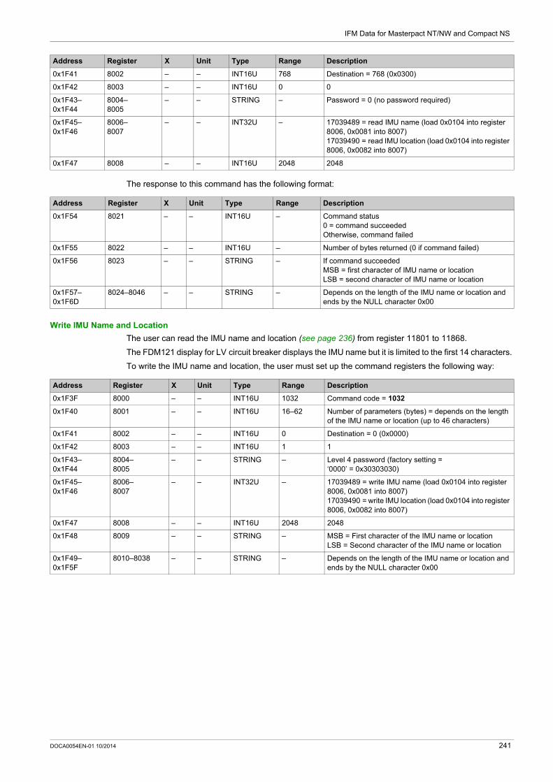
IFM Data for Masterpact NT/NW and Compact NS
The response to this command has the following format:
Write IMU Name and Location
The user can read the IMU name and location (see page 236) from register 11801 to 11868.
The FDM121 display for LV circuit breaker displays the IMU name but it is limited to the first 14 characters.
To write the IMU name and location, the user must set up the command registers the following way:
0x1F41 8002 – – INT16U 768 Destination = 768 (0x0300)
0x1F42 8003 – – INT16U 0 0
0x1F43–0x1F44
8004–8005
– – STRING – Password = 0 (no password required)
0x1F45–0x1F46
8006–8007
– – INT32U – 17039489 = read IMU name (load 0x0104 into register 8006, 0x0081 into 8007)17039490 = read IMU location (load 0x0104 into register 8006, 0x0082 into 8007)
0x1F47 8008 – – INT16U 2048 2048
Address Register X Unit Type Range Description
Address Register X Unit Type Range Description
0x1F54 8021 – – INT16U – Command status0 = command succeededOtherwise, command failed
0x1F55 8022 – – INT16U – Number of bytes returned (0 if command failed)
0x1F56 8023 – – STRING – If command succeededMSB = first character of IMU name or locationLSB = second character of IMU name or location
0x1F57– 0x1F6D
8024–8046 – – STRING – Depends on the length of the IMU name or location and ends by the NULL character 0x00
Address Register X Unit Type Range Description
0x1F3F 8000 – – INT16U 1032 Command code = 1032
0x1F40 8001 – – INT16U 16–62 Number of parameters (bytes) = depends on the length of the IMU name or location (up to 46 characters)
0x1F41 8002 – – INT16U 0 Destination = 0 (0x0000)
0x1F42 8003 – – INT16U 1 1
0x1F43–0x1F44
8004–8005
– – STRING – Level 4 password (factory setting = ‘0000’ = 0x30303030)
0x1F45–0x1F46
8006–8007
– – INT32U – 17039489 = write IMU name (load 0x0104 into register 8006, 0x0081 into 8007)17039490 = write IMU location (load 0x0104 into register 8006, 0x0082 into 8007)
0x1F47 8008 – – INT16U 2048 2048
0x1F48 8009 – – STRING – MSB = First character of the IMU name or locationLSB = Second character of the IMU name or location
0x1F49– 0x1F5F
8010–8038 – – STRING – Depends on the length of the IMU name or location and ends by the NULL character 0x00
DOCA0054EN-01 10/2014 241

IFM Data for Masterpact NT/NW and Compact NS
242 DOCA0054EN-01 10/2014

Masterpact NT/NW, Compact NS
IFE Data for Masterpact NT/NW and Compact NS
DOCA0054EN-01 10/2014
IFE Data for Masterpact NT/NW and Compact NS
Chapter 8IFE Data for Masterpact NT/NW and Compact NS
What Is in This Chapter?
This chapter contains the following sections:
Section Topic Page
8.1 IFE Registers 244
8.2 IFE Commands 249
DOCA0054EN-01 10/2014 243

IFE Data for Masterpact NT/NW and Compact NS
IFE Registers
Section 8.1IFE Registers
What Is in This Section?
This section contains the following topics:
Topic Page
IFE Identification and Status Registers 245
IP Network Parameters 248
244 DOCA0054EN-01 10/2014

IFE Data for Masterpact NT/NW and Compact NS
IFE Identification and Status Registers
IFE Firmware Version
The IFE firmware version starts at register 11776 and has a maximum length of 8 registers.
The firmware version is an ASCII string using the format XXX.YYY.ZZZ with: XXX = major version (000–127) YYY = minor version (000–255) ZZZ = revision number (000–255)
The NULL character ends the revision number.
IFE Hardware Version
The IFE hardware version starts at register 11784 and has a maximum length of 8 registers.
The hardware version is an ASCII string using the format XXX.YYY.ZZZ with: XXX = major version (000–127) YYY = minor version (000–255) ZZZ = revision number (000–255)
The NULL character ends the revision number.
IMU Identification
Identification of the intelligent modular unit (IMU) can be set by using the customer engineering tool (see page 15). When not programmed, the IMU identification registers return 0 (0x0000).
The FDM121 display for LV circuit breaker displays the first 14 characters of the IMU name.
Locking Pad Position
Current Date and Time
Address Register RW X Unit Type Range Description
0x2DFF–0x2E06
11776–11783
R – – STRING – Firmware version
Address Register RW X Unit Type Range Description
0x2E07–0x2E0C
11784–11789
R – – STRING – Hardware version
Address Register RW X Unit Type Range Description
0x2E18–0x2E2E
11801–11823
R – – STRING – IMU name = up to 45 ASCII characters ended by the NULL character 0x00
0x2E45–0x2E5B
11846–11868
R – – STRING – IMU location = up to 45 ASCII characters ended by the NULL character 0x00
Address Register RW X Unit Type Range Description
0x2E72 11891 R – – INT16U 1–3 Locking pad position1 = locking pad is in the locked position3 = locking pad is in the unlocked position
Address Register RW X Unit Type Range Description
0x2E73–0x2E76
11892–11895
RW – – TI081 – Current date and time in TI081 format
0x2E77–0x2E7A
11896–11899
R – – ULP – Current date and time in ULP format
DOCA0054EN-01 10/2014 245

IFE Data for Masterpact NT/NW and Compact NS
Product Identification
Read Device Identification
The Read Device Identification function is used to access in a standardized manner the information required to identify a device clearly. The description is made up of a set of objects (ASCII character strings).
A complete description of the Read Device Identification function is available at www.modbus.org.
The coding for the identification of the IFE is the following:
MAC Address of the IFE
Manufacturing Date and Time
Serial Number
The IFE serial number is composed of a maximum of 11 alphanumeric characters with the following format: PPYYWWDnnnn. PP = plant code YY = year of fabrication (05–99) WW = week of fabrication (01–53) D = day of fabrication (1–7) nnnn = sequence number (0001–9999)
A read request of 6 registers is necessary to read the IFE serial number.
Address Register RW X Unit Type Range Description
0x2E7C 11901 R – – INT16U 17100–17101
Product identification: 17100 for IFE (commercial reference LV434010) 17101 for IFE gateway (commercial reference
LV434011)
Name Type Description
Vendor name STRING ‘Schneider Electric’ (18 characters)
Product code STRING ‘LV434010’ or ’LV434011’
Firmware version STRING ‘XXX.YYY.ZZZ’
Vendor URL STRING ‘www.schneider-electric.com’ (26 characters)
Product name STRING For IFE without gateway (LV434010):‘Ethernet interface for LV breakers’
For IFE with gateway (LV434011):‘Ethernet interface for LV breakers + gateway’
Address Register RW X Unit Type Range Description
0x2E7D–0x2E7F
11902–11904
R – – INT16U – MAC address of the IFE coded over 3 registers (6 bytes) in hexadecimal.Example: The MAC address 00:80:F4:02:12:34 (or 00-80-F4-02-12-34) is coded in hexadecimal as follows: 0080F4021234 (0x00 0x80 0xF4 0x02 0X12 0x34).
Address Register RW X Unit Type Range Description
0x2E89–0x2E8C
11914–11917
R – – TI081 – Manufacturing date and time
Address Register RW X Unit Type Range Description
0x02E91 11922 R – – STRING – ‘PP’
0x02E92 11923 R – – STRING ‘05’–‘99’ ‘YY’
0x02E93 11924 R – – STRING ‘01’–‘53’ ‘WW’
0x02E94 11925 R – – STRING D: ‘1’–‘7’n: ‘0’–‘9’
‘Dn’
0x02E95 11926 R – – STRING ‘00’–‘99’ ‘nn’
0x02E96 11927 R – – STRING ‘0’–‘9’ ‘n’ (the NULL character ends the serial number)
246 DOCA0054EN-01 10/2014

IFE Data for Masterpact NT/NW and Compact NS
IFE Modbus Parameters (IFE Gateway Only)
Address Register RW X Unit Type Range Description
0x306F 12400 R – – INT16U – Modbus address of IFE (always 255)
0x3070 12401 R – – INT16U 1–3 Modbus parity1 = no parity2 = even parity (factory setting)3 = odd parity
0x3071 12402 R – – INT16U 5–8 Modbus Baud rate6 = 9600 Baud7 = 19,200 Baud (factory setting)8 = 38,400 Baud
0x3072 12403 R – – INT16U 0–5 Number of stop bits1 = Auto (factory setting)3 = 1 stop bit5 = 2 stop bits
DOCA0054EN-01 10/2014 247

IFE Data for Masterpact NT/NW and Compact NS
IP Network Parameters
Network Parameters
IPv4 Parameters
Address Register RW X Unit Type Range Description
0x27FF–0x2800
10240–10241
R – – INT32U 0–1 Network configuration mode0 = IPv4 only1 = IPv4 and IPv6
0x2801–0x2808
10242–10249
R – – STRING – Network host name, set by using the customer engineering tool (see page 15)Device name used for acquiring the IP addressing using DHCP and also the friendly name on DPWS device discovery.Example: IFE-0A129FMaximum length is 64 characters.
0x2809–0x2820
10250–10273
– – – – – Reserved
0x2821–0x2822
10274–10275
– – – – – Reserved
Address Register RW X Unit Type Range Description
0x2823–0x2824
10276–10277
R – – INT32U 0–3 IPv4 address acquisition mode, set by using the customer engineering tool (see page 15)0 = Static1 = BootP2 = DHCP3 = Default
0x2825–0x2826
10278–10279
R – – INT32U – IPv4 address acquisition status0 = IP acquisition successful1 = IP acquisition in progress2 = Acquired IP address is duplicated3 = Error in IP acquisition
0x2827–0x2828
10280–10281
R – – INT32U – IPv4 address of IFEExample: 169.254.1.1Register 10280 = 0xA9FERegister 10281 = 0x0101
0x2829–0x282A
10282–10283
R – – INT32U – IPv4 subnet maskExample: 255.255.0.0Register 10282 = 0xFFFFRegister 10283 = 0x0000
0x282B–0x282C
10284–10285
R – – INT32U – IPv4 default gateway addressExample: 169.154.1.1Register 10284 = 0xA9FERegister 10285 = 0x0101
0x282D–0x2846
10286–10311
– – – – – Reserved
248 DOCA0054EN-01 10/2014

IFE Data for Masterpact NT/NW and Compact NS
IFE Commands
Section 8.2IFE Commands
What Is in This Section?
This section contains the following topics:
Topic Page
List of IFE Commands and Error Codes 250
IFE Generic Commands 251
DOCA0054EN-01 10/2014 249

IFE Data for Masterpact NT/NW and Compact NS
List of IFE Commands and Error Codes
List of Commands
The following table lists the IFE commands, their corresponding command codes and password levels. Follow the command execution procedures accordingly (see page 52).
Error Codes
Error codes generated by the IFE are the generic error codes (see page 55).
Command Command Code Password Level
Get current time 768 no password required
Set absolute time 769 no password required
Read IMU name and location 1024 no password required
Write IMU name and location 1032 4
250 DOCA0054EN-01 10/2014

IFE Data for Masterpact NT/NW and Compact NS
IFE Generic Commands
Get Current Time
The get current time command is not hardware protected. The get current time command is still enabled when the locking pad located on the front panel on the IFE is in locked position.
To get the current time for all modules, the user must set up the command registers the following way:
The following registers contain the time data: Register 8023 holds the month in the MSB, the day in the LSB. Register 8024 holds the year offset in the MSB (add 2000 to get the year) and the hour in the LSB. Register 8025 holds the minutes in the MSB, the seconds in the LSB. Register 8026 holds the milliseconds.
Set Absolute Time
The set absolute time command is still enabled when the locking pad located on the front panel on the IFE is in locked position.
To set the absolute time for all the IMU modules, the user must set up the command registers the following way:
In case of 24 Vdc power loss, date and time counter is reset and will restart at January 1 2000. It is therefore mandatory to set absolute time for all the IMU modules after recovering the 24 Vdc power supply.
Furthermore, due to the clock drift of each IMU module, it is mandatory to set absolute time for all the IMU modules periodically. Recommended period is at least every 15 minutes.
Address Register X Unit Type Range Description
0x1F3F 8000 – – INT16U 768 Command code = 768
0x1F40 8001 – – INT16U 10 Number of parameters (bytes) = 10
0x1F41 8002 – – INT16U 8704 Destination = 8704 (0x2200)
0x1F42 8003 – – INT16U 0 0
0x1F43–0x1F44
8004–8005
– – STRING 0 Password = 0 (no password required)
Address Register X Unit Type Range Description
0x1F3F 8000 – – INT16U 769 Command code = 769
0x1F40 8001 – – INT16U 18 Number of parameters (bytes) = 18
0x1F41 8002 – – INT16U 8704 Destination = 8704 (0x2200)
0x1F42 8003 – – INT16U 0 0
0x1F43–0x1F44
8004–8005
– – STRING 0 Password = 0 (no password required)
0x1F45 8006 – – INT16U – MSB = month (1–12)LSB = day in the month (1–31)
0x1F46 8007 – – INT16U – MSB = year (0–99, 0 meaning year 2000)LSB = hour (0–23)
0x1F47 8008 – – INT16U – MSB = minute (0–59)LSB = second (0–59)
0x1F48 8009 – ms INT16U 0–999 Milliseconds (0–999)
DOCA0054EN-01 10/2014 251

IFE Data for Masterpact NT/NW and Compact NS
Read IMU Name and Location
The user can read the IMU name and location (see page 245) from register 11801 to 11868.
The FDM121 display for LV circuit breaker displays the IMU name but it is limited to the first 14 characters.
To read the IMU name and location, the user must set up the command registers the following way:
The response to this command has the following format:
Write IMU Name and Location
The user can read the IMU name and location (see page 245) from register 11801 to 11868.
The FDM121 display for LV circuit breaker displays the IMU name but it is limited to the first 14 characters.
To write the IMU name and location, the user must set up the command registers the following way:
Address Register X Unit Type Range Description
0x1F3F 8000 – – INT16U 1024 Command code = 1024
0x1F40 8001 – – INT16U 16 Number of parameters (bytes) = 16
0x1F41 8002 – – INT16U 8704 Destination = 8704 (0x2200)
0x1F42 8003 – – INT16U 0 0
0x1F43–0x1F44
8004–8005
– – STRING – Password = 0 (no password required)
0x1F45–0x1F46
8006–8007
– – INT32U – 17039489 = read IMU name (load 0x0104 into register 8006, 0x0081 into 8007)17039490 = read IMU location (load 0x0104 into register 8006, 0x0082 into 8007)
0x1F47 8008 – – INT16U 2048 2048
Address Register X Unit Type Range Description
0x1F54 8021 – – INT16U – Command status0 = command succeededOtherwise, command failed
0x1F55 8022 – – INT16U – Number of bytes returned (0 if command failed)
0x1F56 8023 – – STRING – If command succeededMSB = first character of IMU name or locationLSB = second character of IMU name or location
0x1F57–0x1F6D
8024–8046 – – STRING – Depends on the length of the IMU name or location and ends by the NULL character 0x00
Address Register X Unit Type Range Description
0x1F3F 8000 – – INT16U 1032 Command code = 1032
0x1F40 8001 – – INT16U 16–62 Number of parameters (bytes) = depends on the length of the IMU name or location (up to 46 characters)
0x1F41 8002 – – INT16U 0 Destination = 0 (0x0000)
0x1F42 8003 – – INT16U 1 1
0x1F43–0x1F44
8004–8005
– – STRING – Level 4 password (factory setting = ‘0000’ = 0x30303030)
0x1F45–0x1F46
8006–8007
– – INT32U – 17039489 = write IMU name (load 0x0104 into register 8006, 0x0081 into 8007)17039490 = write IMU location (load 0x0104 into register 8006, 0x0082 into 8007)
0x1F46 8008 – – INT16U 2048 2048
0x1F48 8009 – – STRING – MSB = First character of the IMU name or locationLSB = Second character of the IMU name or location
0x1F49–0x1F5F
8010–8038
– – STRING – Depends on the length of the IMU name or location and ends by the NULL character 0x00
252 DOCA0054EN-01 10/2014

Masterpact NT/NW, Compact NS
DOCA0054EN-01 10/2014
Appendices
DOCA0054EN-01 10/2014 253

254 DOCA0054EN-01 10/2014

Masterpact NT/NW, Compact NS
Cross References to Modbus Registers for Masterpact NT/NW and Compact NS
DOCA0054EN-01 10/2014
Cross References to Modbus Registers for Masterpact NT/NW and Compact NS
Appendix ACross References to Modbus Registers for Masterpact NT/NW and Compact NS
Cross References to Modbus Registers
General Description
The following table gives cross references to the Modbus registers used by the communication modules. The registers are listed in ascending order.
Cross References Table
Address Register Module Description Page
0x0095–0x009B 150–156 BCM ULP Trip history (see page 193)
0x0202 515 BCM ULP Product identification (see page 187)
0x0215–0x021E 534–543 BCM ULP BCM ULP identifier (see page 187)
0x0229–0x022A 554–555 BCM ULP BCM ULP counters (see page 192)
0x0240 577 BCM ULP Firmware version (see page 187)
0x0243–0x0244 580–581 BCM ULP Counter thresholds (see page 192)
0x0289–0x028A 650–651 BCM ULP Tripping cause (see page 188)
0x0291–0x0292 658–659 BCM ULP Inhibit close order (see page 189)
0x0293 660 BCM ULP Local/remote mode (see page 189)
0x0294 661 BCM ULP Circuit breaker status (see page 189)
0x0295–0x0298 662–665 BCM ULP Circuit breaker operation counters (see page 192)
0x029D 670 BCM ULP Auto/Manu mode (see page 190)
0x029E–0x02A0 671–673 BCM ULP Date of last actuation of MX auxiliary (see page 191)
0x02A1 674 BCM ULP MX actuation counter (see page 192)
0x02A2 675 BCM ULP Date of last actuation of XF auxiliary (see page 191)
0x02A5 678 BCM ULP XF actuation counter (see page 192)
0x02A6–0x02A9 679–682 BCM ULP Current date of BCM ULP (see page 191)
0x02AB–0x02BD 684–702 BCM ULP Date of last event (see page 191)
0x031F 800 BCM ULP Legacy data-set activation (see page 190)
0x0325 806 BCM ULP Communication parameter (see page 190)
0x032C 813 BCM ULP Contact wear (see page 190)
0x03E7–0x03F6 1000–1015 Micrologic trip unit Voltage and voltage unbalance (real time-measurements)
(see page 99)
0x03F7–0x0407 1016–1032 Micrologic trip unit Current and current unbalance (real time-measurements)
(see page 100)
0x0409–0x0414 1034–1045 Micrologic trip unit Active, reactive, and apparent power (real time-measurements)
(see page 100)
0x0415–0x041C 1046–1053 Micrologic trip unit Power factor and fundamental power factor (real time-measurements)
(see page 101)
0x041D 1054 Micrologic trip unit Frequency (real time-measurements) (see page 102)
0x041F–0x0424 1056–1061 Micrologic trip unit Fundamental voltage (real time-measurements)
(see page 102)
0x042B–0x042E 1068–1071 Micrologic trip unit Fundamental current (real time-measurements)
(see page 102)
0x0433–0x0436 1076–1079 Micrologic trip unit Fundamental active power (real time-measurements)
(see page 102)
0x0437–0x043A 1080–1083 Micrologic trip unit Fundamental reactive power (real time-measurements)
(see page 102)
DOCA0054EN-01 10/2014 255

Cross References to Modbus Registers for Masterpact NT/NW and Compact NS
0x043B–0x043E 1084–1087 Micrologic trip unit Fundamental apparent power (real time-measurements)
(see page 103)
0x043F–0x0442 1088–1091 Micrologic trip unit Distortion power (real time-measurements) (see page 103)
0x0443–0x044C 1092–1101 Micrologic trip unit Total harmonic distortion in relation to the fundamental (THD) (real time-measurements)
(see page 103)
0x044D–0x0456 1102–1111 Micrologic trip unit Total harmonic distortion in relation to the RMS Value (thd) (real time-measurements)
(see page 104)
0x0457–0x0459 1112–1114 Micrologic trip unit Voltage to current phase shift (real time-measurements)
(see page 104)
0x045A–0x045D 1115–1118 Micrologic trip unit K-Factor (real time-measurements) (see page 104)
0x045E–0x0467 1119–1128 Micrologic trip unit Peak factor (real time-measurements) (see page 105)
0x046C–0x046E 1133–1135 Micrologic trip unit Voltage-to-voltage phase shift (real time-measurements)
(see page 105)
0x0513–0x0522 1300–1315 Micrologic trip unit Voltage (minimum of real-time measurement) (see page 106)
0x0523–0x0533 1316–1332 Micrologic trip unit Current (minimum of real-time measurement) (see page 106)
0x0535–0x0540 1334–1345 Micrologic trip unit Active, reactive, and apparent power (minimum of real-time measurement)
(see page 106)
0x0541–0x0548 1346–1353 Micrologic trip unit Power factor (minimum of real-time measurement)
(see page 106)
0x0549–0x054A 1354–1355 Micrologic trip unit Frequency (minimum of real-time measurement)
(see page 106)
0x054B–0x0551 1356–1362 Micrologic trip unit Fundamental voltage (minimum of real-time measurement)
(see page 106)
0x0557–0x055B 1368–1372 Micrologic trip unit Fundamental current (minimum of real-time measurement)
(see page 106)
0x055F–0x0562 1376–1379 Micrologic trip unit Fundamental active power (minimum of real-time measurement)
(see page 106)
0x0563–0x0566 1380–1383 Micrologic trip unit Fundamental reactive power (minimum of real-time measurement)
(see page 106)
0x0567–0x056A 1384–1387 Micrologic trip unit Fundamental apparent power (minimum of real-time measurement)
(see page 106)
0x056B–0x056E 1388–1391 Micrologic trip unit Distortion power (minimum of real-time measurement)
(see page 106)
0x056–0x0578 1392–1401 Micrologic trip unit Total harmonic distortion in relation to the fundamental (THD) (minimum of real-time measurement)
(see page 106)
0x0579–0x0582 1402–1411 Micrologic trip unit Total harmonic distortion in relation to the RMS Value (thd) (minimum of real-time measurement)
(see page 106)
0x0583–0x0585 1412–1414 Micrologic trip unit Voltage to current phase shift (minimum of real-time measurement)
(see page 106)
0x0586–0x0589 1415–1418 Micrologic trip unit K-Factor (minimum of real-time measurement)
(see page 106)
0x058A–0x0593 1419–1428 Micrologic trip unit Peak factor (minimum of real-time measurement)
(see page 106)
0x0598–0x059A 1433–1435 Micrologic trip unit Voltage-to-voltage phase shift (minimum of real-time measurement)
(see page 106)
0x063F–0x064E 1600–1615 Micrologic trip unit Voltage (maximum of real-time measurement)
(see page 106)
0x064F–0x065F 1616–1632 Micrologic trip unit Current (maximum of real-time measurement) (see page 106)
0x0661–0x066C 1634–1645 Micrologic trip unit Active, reactive, and apparent power (maximum of real-time measurement)
(see page 106)
0x066D–0x0674 1646–1653 Micrologic trip unit Power factor (maximum of real-time measurement)
(see page 106)
0x0675–0x0676 1654–1655 Micrologic trip unit Frequency (maximum of real-time measurement)
(see page 106)
0x0677–0x067D 1656–1662 Micrologic trip unit Fundamental voltage (maximum of real-time measurement)
(see page 106)
Address Register Module Description Page
256 DOCA0054EN-01 10/2014

Cross References to Modbus Registers for Masterpact NT/NW and Compact NS
0x0683–0x0687 1668–1672 Micrologic trip unit Fundamental current (maximum of real-time measurement)
(see page 106)
0x068B–0x068E 1676–1679 Micrologic trip unit Fundamental active power (maximum of real-time measurement)
(see page 106)
0x068F–0x0692 1680–1683 Micrologic trip unit Fundamental reactive power (maximum of real-time measurement)
(see page 106)
0x0693–0x0696 1684–1687 Micrologic trip unit Fundamental apparent power (maximum of real-time measurement)
(see page 106)
0x0697–0x069A 1688–1691 Micrologic trip unit Distortion power (maximum of real-time measurement)
(see page 106)
0x069B–0x06A4 1692–1701 Micrologic trip unit Total harmonic distortion in relation to the fundamental (THD) (maximum of real-time measurement)
(see page 106)
0x06A5–0x06AE 1702–1711 Micrologic trip unit Total harmonic distortion in relation to the RMS Value (thd) (maximum of real-time measurement)
(see page 106)
0x06AF–0x06B1 1712–1714 Micrologic trip unit Voltage to current phase shift (maximum of real-time measurement)
(see page 106)
0x06B2–0x06B5 1715–1718 Micrologic trip unit K-Factor (maximum of real-time measurement)
(see page 106)
0x06B6–0x06BF 1719–1728 Micrologic trip unit Peak factor (maximum of real-time measurement)
(see page 106)
0x06C4–0x06C6 1733–1735 Micrologic trip unit Voltage-to-voltage phase shift (maximum of real-time measurement)
(see page 106)
0x07CF–0x07EA 2000–2027 Micrologic trip unit Energy measurements (see page 107)
0x0897–0x08C0 2200–2241 Micrologic trip unit Demand measurements (see page 108)
0x0BB7–0x0BF7 3000–3064 Micrologic trip unit Time-stamped information (see page 154)
0x0CE6–0x0CEF 3303–3312 Micrologic trip unit Identification of the metering manager (see page 115)
0x0CF1 3314 Micrologic trip unit System type (see page 151)
0x0CF3 3316 Micrologic trip unit Power flow sign (see page 151)
0x0CF4 3317 Micrologic trip unit Power reactive sign (see page 151)
0x0CF5 3318 Micrologic trip unit Power factor sign (see page 152)
0x0CF6 3319 Micrologic trip unit Reactive power calculation convention (see page 152)
0x0CFB 3324 Micrologic trip unit Energy accumulation mode (see page 152)
0x0D16–0x0D1A 3351–3355 Micrologic trip unit Demand time (see page 152)
0x0EE7 3816 Micrologic trip unit Product identification (with metering manager)
(see page 115)
0x1003–0x105C 4100–4189 Micrologic trip unit Amplitude of voltage harmonic(odd rank)
(see page 110)
0x105D–0x1098 4190–4249 Micrologic trip unit Amplitude of current harmonic(odd rank)
(see page 112)
0x1099–0x10AA 4250–4267 Micrologic trip unit Phase of voltage harmonic(odd rank)
(see page 113)
0x10F3–0x1102 4340–4355 Micrologic trip unit Phase of current harmonic(odd rank)
(see page 114)
0x112F–0x1188 4400–4489 Micrologic trip unit Amplitude of voltage harmonic(even rank)
(see page 110)
0x1189–0x11C4 4490–4549 Micrologic trip unit Amplitude of current harmonic(even rank)
(see page 110)
0x11C5–0x11D6 4550–4567 Micrologic trip unit Phase of voltage harmonic(even rank)
(see page 110)
0x121F–0x122E 4640–4655 Micrologic trip unit Phase of current harmonic(even rank)
(see page 110)
0x1643–0x1646 5700–5703 Micrologic trip unit Predefined alarms status (see page 118)
0x176F–0x19EA 6000–6635 Micrologic trip unit Analog predefined alarms (see page 125)
0x1F3F–0x1FD4 8000–8149 Micrologic trip unit Command interface (see page 52)
Address Register Module Description Page
DOCA0054EN-01 10/2014 257

Cross References to Modbus Registers for Masterpact NT/NW and Compact NS
0x21FB–0x21FE 8700–8703 Micrologic trip unit Serial number (see page 115)
0x2205 8710 Micrologic trip unit Firmware version (see page 115)
0x220B 8716 Micrologic trip unit Product identification (with protection manager)
(see page 115)
0x2223 8740 Micrologic trip unit Protection type (see page 115)
0x2224 8741 Micrologic trip unit Metering type (A, E, P, H) (see page 116)
0x2225 8742 Micrologic trip unit Long-time rating plug (see page 116)
0x222D 8750 Micrologic trip unit Nominal current (see page 157)
0x2230 8753 Micrologic trip unit Neutral protection parameters (see page 129)
0x2231–0x223A 8754–8763 Micrologic trip unit Long-time protection (see page 129)
0x223B–0x2244 8764–8773 Micrologic trip unit Short-time protection (see page 130)
0x2245–0x224E 8774–8783 Micrologic trip unit Instantaneous protection (see page 130)
0x224F–0x2258 8784–8793 Micrologic trip unit Ground-fault protection (see page 131)
0x2259–0x2262 8794–8803 Micrologic trip unit Earth-leakage (Vigi) protection (see page 132)
0x2263–0x2289 8804–8842 Micrologic trip unit Protection manager measurements (see page 157)
0x228A 8843 Micrologic trip unit Battery status (see page 158)
0x2298 8857 Micrologic trip unit M2C/M6C programmable contacts status (see page 119)
0x229D–0x229F 8862–8864 Micrologic trip unit Protection status (see page 120)
0x22A0–0x22A1 8865–8866 Micrologic trip unit Time remaining until long-time tripping (see page 158)
0x22A7 8872 Micrologic trip unit Phase rotation (see page 158)
0x2327–0x2372 9000–9075 Micrologic trip unit Time-stamped information (see page 154)
0x238B–0x2452 9100–9299 Micrologic trip unit Trip history (see page 123)
0x2583–0x258C 9604–9613 Micrologic trip unit Identification (of the protection manager) (see page 116)
0x258D 9614 Micrologic trip unit Language (see page 158)
0x258E 9615 Micrologic trip unit Nominal frequency (see page 159)
0x258F–0x2590 9616–9617 Micrologic trip unit Nominal voltage Vn (see page 153)
0x2591 9618 Micrologic trip unit Circuit breaker type (see page 116)
0x259C–0x25A5 9629–9638 Micrologic trip unit Ground-fault alarm (see page 133)
0x25A6–0x25AF 9639–9648 Micrologic trip unit Earth-leakage alarm (see page 133)
0x25B0–0x25B9 9649–9658 Micrologic trip unit Current unbalance protection (see page 134)
0x25BA–0x25C3 9659–9668 Micrologic trip unit Maximum current protection on phase 1 (see page 135)
0x25C4–0x25CD 9669–9678 Micrologic trip unit Maximum current protection on phase 2 (see page 136)
0x25CE–0x25D7 9679–9688 Micrologic trip unit Maximum current protection on phase 3 (see page 137)
0x25D8–0x25E1 9689–9698 Micrologic trip unit Maximum current protection on neutral (see page 138)
0x25E2–0x25EB 9699–9708 Micrologic trip unit Minimum voltage protection (see page 139)
0x25EC–0x25F5 9709–9718 Micrologic trip unit Maximum voltage protection (see page 140)
0x25F6–0x25FF 9719–9728 Micrologic trip unit Voltage unbalance protection (see page 141)
0x260A–0x2613 9739–9748 Micrologic trip unit Reverse power protection (see page 142)
0x2614–0x261D 9749–9758 Micrologic trip unit Minimum frequency protection (see page 143)
0x261E–0x2627 9759–9768 Micrologic trip unit Maximum frequency protection (see page 144)
0x2628–0x2631 9769–9778 Micrologic trip unit Phase rotation alarm (see page 145)
0x2632–0x263B 9779–9788 Micrologic trip unit Load shedding and reconnection based on current
(see page 146)
0x263C–0x2645 9789–9798 Micrologic trip unit Load shedding and reconnection based on power
(see page 147)
0x2647 9800 Micrologic trip unit Remote configuration status (see page 149)
0x2648–0x2671 9801–9842 Micrologic trip unit Configuration of the M2C/M6C programmable contacts
(see page 149)
0x2672 9843 Micrologic trip unit Type of M2C/M6C programmable contacts (see page 150)
0x2675–0x267C 9846–9853 Micrologic trip unit Circuit breaker characteristics (see page 117)
0x27FF–0x2826 10240–10279 IFE IP network parameters (see page 248)
Address Register Module Description Page
258 DOCA0054EN-01 10/2014

Cross References to Modbus Registers for Masterpact NT/NW and Compact NS
0x2DFF–0x2E06 11776–11783 IFM Firmware version (see page 235)
0x2DFF–0x2E06 11776–11783 IFE Firmware version (see page 245)
0x2E07–0x2E0C 11784–11789 IFM Serial number (see page 235)
0x2E07–0x2E0C 11784–11789 IFE Hardware version (see page 245)
0x2E18–0x2E2E 11801–11823 IFM IMU name (see page 236)
0x2E18–0x2E2E 11801–11823 IFE IMU name (see page 245)
0x2E45–0x2E5B 11846–11868 IFM IMU location (see page 236)
0x2E45–0x2E5B 11846–11868 IFE IMU location (see page 245)
0x2E72 11891 IFM Modbus locking pad position (see page 237)
0x2E72 11891 IFE Locking pad position (see page 245)
0x2E73–0x2E7A 11892–11899 IFE Current date and time (see page 245)
0x2E7C 11901 IFM Product identification (see page 235)
0x2E7C 11901 IFE Product identification (see page 246)
0x2E7D–0x02E7F 11902–11904 IFE IFE MAC address (see page 246)
0x2E89–0x2E8C 11914–11917 IFE Manufacturing date and time (see page 246)
0x2E91–0x02E96 11922–11931 IFE Serial number (see page 246)
0x2EDF–0x2F84 12000–12165 IFM Legacy data-set (see page 87)
0x2EDF–0x2F84 12000–12165 IFE Legacy data-set (see page 87)
0x306E 12399 IFM Auto-Speed sensing state (see page 237)
0x306F 12400 IFM IFM Modbus address (see page 237)
0x306F–0x3072 12400–12403 IFE IFE Modbus parameters (see page 247)
0x3070 12401 IFM Modbus parity (see page 237)
0x3071 12402 IFM Modbus Baud rate (see page 237)
0x3072 12403 IFM Number of stop bits (see page 237)
0x35FF–0x3668 13824–13929 IO Analog input of IO 1 (see page 203)
0x3669–0x3848 13930–14409 IO Digital input of IO 1 (see page 205)
0x3849–0x38FC 14410–14589 IO Digital output of IO 1 (see page 207)
0x38FD–0x3902 14590–14595 IO Hardware setting of IO 1 (see page 209)
0x3905–0x3908 14598–14601 IO Digital input and output status of IO 1 (see page 210)
0x392F–0x3982 14640–14723 IO IO 1 identification (see page 211)
0x3989–0x39A4 14730–14759 IO Alarm status of IO 1 (see page 213)
0x3BC3–0x3BE0 15300–15329 IO Cradle management of IO 1 (see page 216)
0x3BE1–0x3BFE 15330–15359 IO Drawer management of IO 1 (see page 216)
0x3C27–3C30 15400–15409 IO Light control of IO 1 (see page 217)
0x3C31–3EEC 15410–16109 IO Load control of IO 1 (see page 217)
0x41B8–0x4220 16824–16929 IO Analog input of IO 2 (see page 203)
0x4221–0x4400 16930–17409 IO Digital input of IO 2 (see page 205)
0x4401–0x44B4 17410–17589 IO Digital output of IO 2 (see page 207)
0x44B5–0x44BA 17590–17595 IO Hardware setting of IO 2 (see page 209)
0x44BD–0x44C0 17598–17601 IO Digital input and output status of IO 2 (see page 210)
0x44E7–0x453A 17640–17723 IO IO 2 identification (see page 211)
0x4541–0x455E 17730–17759 IO Alarm status of IO 2 (see page 213)
0x477B–0x4798 18300–18329 IO Cradle management of IO 2 (see page 216)
0x4799–0x47B6 18330–18359 IO Drawer management of IO 2 (see page 216)
0x749C 29853 Micrologic trip unit Rate of wear counter (see page 156)
0x74B7–0x74BE 29880–29887 Micrologic trip unit Load profile counters (see page 156)
0x7CFF–0x7E4E 32000–32341 IFE Standard data-set (see page 70)
Address Register Module Description Page
DOCA0054EN-01 10/2014 259

Cross References to Modbus Registers for Masterpact NT/NW and Compact NS
260 DOCA0054EN-01 10/2014


As standards, specifications and designs change from time to time, please ask for confirmation of the information given in this publication.
DOCA0054EN-01
Schneider Electric Industries SAS35, rue Joseph MonierCS30323F - 92506 Rueil Malmaison Cedex
www.schneider-electric.com 10/2014


