Master’s Thesis A loosely coupled peer-to-peer workflow system carried out at the Information Systems Institute Distributed Systems Group Technical University of Vienna under the guidance of Ao.Univ.Prof. Dr. Schahram Dustdar and Ao.Univ.Prof. Dr. Harald Gall as the contributing advisor responsible by Daniel Schwarz Haberlgasse 30/9, 1160 Vienna Matr.Nr. 9551015 Vienna, 12 May 2004
Transcript
Master’s Thesis
A loosely coupled peer-to-peerworkflow system
carried out at the
Information Systems InstituteDistributed Systems Group
Technical University of Vienna
under the guidance ofAo.Univ.Prof. Dr. Schahram Dustdar
andAo.Univ.Prof. Dr. Harald Gall
as the contributing advisor responsible
by
Daniel SchwarzHaberlgasse 30/9, 1160 Vienna
Matr.Nr. 9551015
Vienna, 12 May 2004
To my parents
Acknowledgments
First I want to thank my advisors Schahram Dustdar and Harald Gall whosupported me during the whole work.
I also want to thank my mother Karoline and my father Karl for theirsupport during the last years. With their patience and support they madeit possible for me to finish my studies and write this master thesis.
i
Abstract
In this thesis we describe a workflow system which is built on top of anexisting peer-to-peer architecture. The goal of this system is to implementa framework which provides the basic infrastructure for flow-controlledand distributed human workflow [1], supported with the service orientedworkflow language BPEL. The domain of the system primarily targets theexecution of formally defined business processes. In order to have partsof the process distributed to different peers, a coordinator is responsiblefor choosing them and assigning the work. The election of the peers isperformed using certain quality criteria which have to be provided by theparticipants of the workflow system.
A main focus in the choice of the used infrastructure as well as in themodeling of the communication structure was to comply with the increas-ing diversity of network clients, which range from mobile devices to per-sonal computers. The information exchange between connected peers hasto serve the requirements of both permanent network connectivity and lim-ited availability. This is achieved by a ”loosely coupled” approach: Theclients gather information in connected state and maintain a local knowl-edge database which provides necessary information if the peer is discon-nected from the network.
ii
Zusammenfassung
In der hier vorgestellten Diplomarbeit wird ein auf eine vorhandenePeer-to-Peer-Architektur aufbauendes Workflow-System beschrieben. Zieldieses Systems ist es, ein Framework zu implementieren, welches eineBasis fur ablaufgesteuerten ”human workflow” liefert. Das Aufgabenge-biet dieser Anwendungen erstreckt sich vorrangig auf das Abhandeln klardefinierter Geschaftsprozesse, welche in der Sprache BPEL beschriebensind. Dabei wird von einem Koordinator versucht, die Ausfuhrung einzel-ner Prozessteile zwischen verschiedenen Peers aufzuteilen. Die Auswahldieser erfolgt unter Zuhilfenahme von Qualitatskriterien, welche von deneinzelnen Peers zur Verfugung gestellt werden.
Ein Hauptaugenmerk bei der Wahl der verwendeten Infrastruktur undbei der Modellierung der Kommunikationsstruktur war es, der immerstarker werdenden Prasenz mobiler Endgerate ebenso Rechnung zu tra-gen wie gewohnlichen PC’s. Dabei wurde versucht, beim Datenaus-tausch zwischen den vernetzten Peers eine vernunftige Balance zwischenlimitierter Verbindungsverfugbarkeit und permanenter Netzanbindung zufinden. Der Ansatz ”loosely coupled” wird dadurch erreicht, dass mit-tels lokalen Wissensdatenbanken auf den Endgeraten auch im Offlinebe-trieb der zuletzt aktuelle Status des Netzwerks verfugbar ist und beimWiederverbinden die notigen Daten synchronisiert werden.
Chapter 1 introduces an example which demonstrates a typical applica-tion we aim to solve and gives a problem definition.
Chapter 2 provides a technological overview of peer-to-peer middle-wares. We also present a suitable language for process definitions and aslim XML database.
In Chapter 3 the detailed ideas of our approach are presented. First wedescribe the software architecture and the main components. Later the con-cepts of process management are discussed.
Chapter 4 shows which user interactions can be applied to the system.The use cases demonstrate the actions the users of the workflow systemcan take and the influence of the different roles the peers can play.
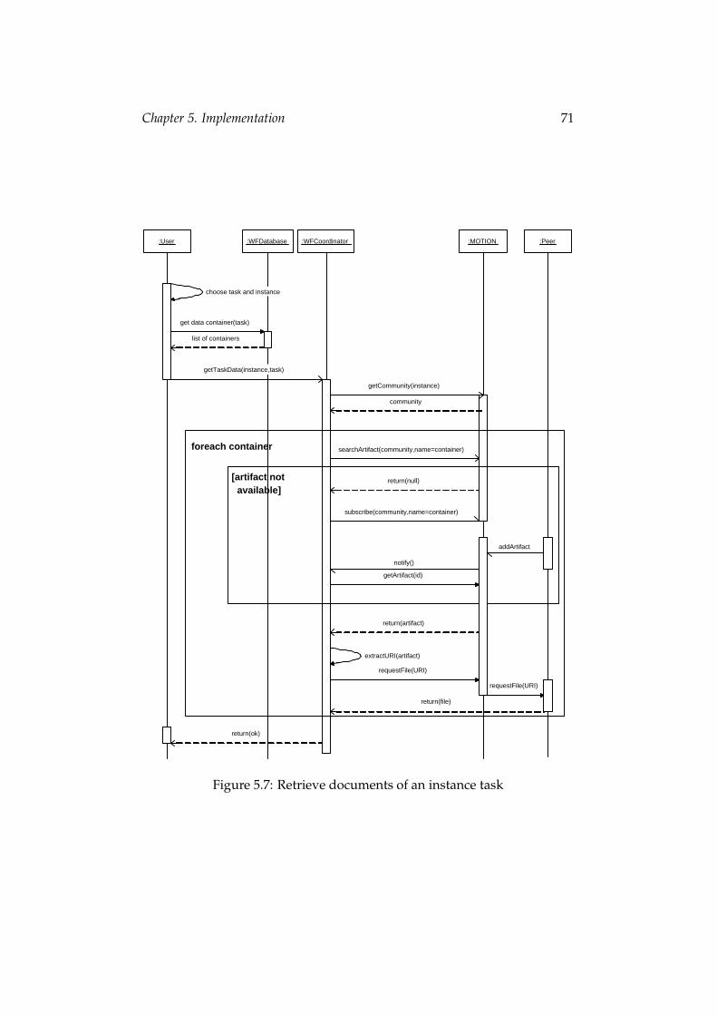
Chapter 5 focuses on some implementation details. First we give a de-scription of the classes and the database storage. Then we describe themessage and document exchange between peers.
Chapter 6 validates the prerequisites against the results which have beenachieved.
In Chapter 7 we outline some future extensions and enhancements of thecurrent implementation in respect of practical issues.
Chapter 1. Introduction 2
1.2 Illustrative Example
In this section I will introduce a workflow example which is used to illus-trate my work in several parts of this thesis. It shows what kind of problemwe address and which we want to solve in this approach. The example istaken from the WSFL specification [2].
Figure 1.1: Airline reservation
A traveler plans a trip by specifying the various stages of his overall jour-ney. For each of the stages, the traveler specifies the location that he wantsto visit as well as the date when he wants to begin and the date when hewants to end the particular stay. When the traveler is finished with this, hesends this information as well as the information about the credit card to becharged for the ordered tickets to the travel agent. Next, the traveler willawait the submission of the electronic tickets as well as the final itineraryfor the trip.
When the agent receives the traveler’s trip order, he will determine thelegs for each of the stages, which includes an initial seat reservation. Toactually make the corresponding ticket orders the agent submits these legstogether with the information about the credit card to be charged to theairline company. Then, the agent waits for the confirmation of the flights,
Chapter 1. Introduction 3
which especially includes the actual seats reserved for each of the partici-pants. This information is completed into an itinerary, which is then sentto the traveler.
When the airline receives the ticket order submitted by the agent, therequested seats will be checked and if available assigned to the traveler.After that, the credit card will be charged, and the updated leg informationis sent back to the agent as confirmation of the flights. After that, the airlinesends the electronic tickets to the traveler. Information about the recipientof the tickets has been specified by the traveler when instantiating the triporder process and this information is passed to the agent as well as to theairline.
Chapter 1. Introduction 4
1.3 Problem Definition
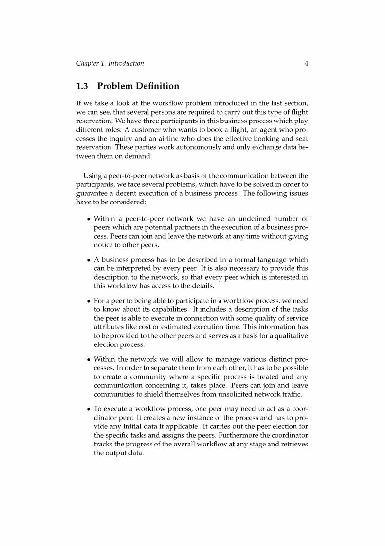
If we take a look at the workflow problem introduced in the last section,we can see, that several persons are required to carry out this type of flightreservation. We have three participants in this business process which playdifferent roles: A customer who wants to book a flight, an agent who pro-cesses the inquiry and an airline who does the effective booking and seatreservation. These parties work autonomously and only exchange data be-tween them on demand.
Using a peer-to-peer network as basis of the communication between theparticipants, we face several problems, which have to be solved in order toguarantee a decent execution of a business process. The following issueshave to be considered:
• Within a peer-to-peer network we have an undefined number ofpeers which are potential partners in the execution of a business pro-cess. Peers can join and leave the network at any time without givingnotice to other peers.
• A business process has to be described in a formal language whichcan be interpreted by every peer. It is also necessary to provide thisdescription to the network, so that every peer which is interested inthis workflow has access to the details.
• For a peer to being able to participate in a workflow process, we needto know about its capabilities. It includes a description of the tasksthe peer is able to execute in connection with some quality of serviceattributes like cost or estimated execution time. This information hasto be provided to the other peers and serves as a basis for a qualitativeelection process.
• Within the network we will allow to manage various distinct pro-cesses. In order to separate them from each other, it has to be possibleto create a community where a specific process is treated and anycommunication concerning it, takes place. Peers can join and leavecommunities to shield themselves from unsolicited network traffic.
• To execute a workflow process, one peer may need to act as a coor-dinator peer. It creates a new instance of the process and has to pro-vide any initial data if applicable. It carries out the peer election forthe specific tasks and assigns the peers. Furthermore the coordinatortracks the progress of the overall workflow at any stage and retrievesthe output data.
Chapter 1. Introduction 5
• As all peers work autonomously, they will only be provided with theminimum amount of information necessary. Hence, they have a localview of the problem and don’t know about the global scope of theworkflow.
• We want to take into account the participation of mobile clients aspeers in terms of availability and network load. Such clients will notbe permanently connected to the network and will have limited band-width compared with other peers.
6
Chapter 2
Used Technology
2.1 Peer to Peer
The first peer-to-peer (P2P) technologies emerged more than a decade agoto facilitate communication and resource utilization within the enterprise.Today, P2P describes the general model of using direct communication be-tween all devices on the network. P2P brings connectivity to the edge ofthe network, enabling any connected device on the network to communi-cate and collaborate. With P2P, applications can be more collaborative andcommunication-focused, and information can be more timely and accurate.
While P2P is not a specific architecture or technology, it does enable anumber of innovative applications, including:
• Sharing files of all types
• New forms of content distribution and delivery
• Instant messaging and pervasive devices communicating
• Collaborative work and play such as Web-based meetings and inter-active gaming
• Distributed search and indexing to enable deep searches of Internetcontent that quickly yield up-to-the-minute results
• Sharing CPU and storage resources to better utilize capital invest-ments
Chapter 2. Used Technology 7
2.1.1 PeerWare
The advantages of a peer-to-peer architecture go well beyond the realmof Internet file sharing, becoming crucial in supporting business processesand especially collaborative work involving mobile users. Targeting on thisissue, PeerWare [3, 4] was designed as a core communication middlewarefor TeamWork applications.
Collaborative work is intrinsically peer-to-peer in nature. Members of ateam typically interact directly with each other, with each member beingresponsible for a given set of documents and carrying with them the subsetrelevant for discussion. On the other hand, most of the currently availabletools supporting collaboration exploit a rigid client-server architecture.This results in an ’architectural mismatch’ between the external view pro-vided by the application and its internal software architecture. The effect ofthis mismatch is a lack of flexibility in carrying out the interactions, whichmust all be funneled through the server. This limitation is even more evi-dent when mobility becomes part of the picture. People need to communi-cate and collaborate even while in movement, and independently of theirlocation. However, in similar situations, server access is often prevented bytechnical or administrative barriers.A peer-to-peer approach holds significant advantages over traditionalclient-server architectures. When a peer-to-peer architecture is adopted,data and services are no longer gathered in a single point of accumula-tion. Instead, they are spread across all the nodes of the distributed system.Users may directly host the resources they want to share with others, withno need to publish them on a particular server.Interestingly, these features are relevant not only in mobile scenarios butalso in fixed ones, where the decentralized nature of a peer-to-peer architec-ture naturally encompasses the case of multisite or multicompany projects,whose cooperation infrastructure must span administrative boundaries,and is subject to security concerns.
Unfortunately, most of the peer-to-peer applications developed in recentyears started from promises that are rather different from those outlinedthus far. They target the Internet and aim at providing peer-to-peer com-puting over millions of nodes, with file sharing as their main applicationconcern. The difference in perspective from the domain of collaborativework is made evident by their search capabilities, which typically do notguarantee to capture information about all matching files. In most casesthey do not take into consideration features like security or the ability tosupport reactive interactions, which are crucial in cooperative business ap-plications. Moreover, they bring peer-to-peer to an extreme, where the logi-cal network of peers is totally fluid, and no peer can be assumed to be fixed
Chapter 2. Used Technology 8
Figure 2.1: The data structure managed by PeerWare.
and contributing to the definition of a permanent infrastructure. This rad-ical view prevents access to resources exported by non-connected peers,which is unacceptable in the business world, where critical data is oftenrequired to be always available, independently of its owner.
On the basis of the above considerations, PeerWare was developed:a peer-to-peer middleware for teamwork support specifically geared to-wards the enterprise domain. PeerWare is both a model and an incarnationof this model in a middleware. In developing both, the first concerns wereminimality and flexibility.
The model The PeerWare coordination model exploits the notion of aglobal virtual data structure (GVDS), which is a generalization of the LIME[5] coordination model. Coordination among units is enabled through adata space that is transiently shared and dynamically built out of the dataspaces provided by each accessible unit. The data structure managed byPeerWare is a hierarchy of nodes containing documents, where a documentmay actually be accessible from multiple nodes, as shown in Figure 2.1.This structure resembles a standard file system, where directories play therole of nodes, files are the documents, and Unix-like hard links are allowedonly on documents.When a peer is isolated, it is only given access to its own tree (stored locally)of items (i.e., nodes and documents). However, when connectivity withother peers is established, the peer has access to the virtual tree constructed
Chapter 2. Used Technology 9
by superimposing the trees contributed by all the peers in the system, asillustrated by Figure 2.2.
Figure 2.2: Building the GVDS in PeerWare.
In search of minimality, PeerWare provides only three main operations tooperate on the GVDS:
• the execute operation allows peers to execute an arbitrary piece ofcode on a selected set of items held by connected peers. The resultsare collected and returned to the caller
• the subscribe operation allows peers to subscribe to events occurringon a selected set of items, while
• the publish operation allows peers to notify the occurrence of events.
By exploiting these primitives, peers can query the GVDS and also sub-scribe to events and receive the corresponding notifications. The hierar-chical structure of the GVDS provides a natural scoping mechanism, thusleading to an efficient implementation of searches.
Chapter 2. Used Technology 10
Backbonepeer
Non−backbonepeer
Lighweightpeer
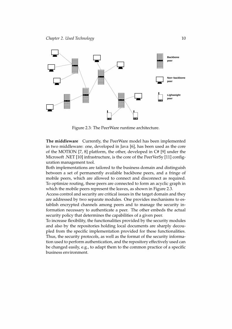
Figure 2.3: The PeerWare runtime architecture.
The middleware Currently, the PeerWare model has been implementedin two middleware: one, developed in Java [6], has been used as the coreof the MOTION [7, 8] platform, the other, developed in C# [9] under theMicrosoft .NET [10] infrastructure, is the core of the PeerVerSy [11] config-uration management tool.Both implementations are tailored to the business domain and distinguishbetween a set of permanently available backbone peers, and a fringe ofmobile peers, which are allowed to connect and disconnect as required.To optimize routing, these peers are connected to form an acyclic graph inwhich the mobile peers represent the leaves, as shown in Figure 2.3.Access control and security are critical issues in the target domain and theyare addressed by two separate modules. One provides mechanisms to es-tablish encrypted channels among peers and to manage the security in-formation necessary to authenticate a peer. The other embeds the actualsecurity policy that determines the capabilities of a given peer.To increase flexibility, the functionalities provided by the security modulesand also by the repositories holding local documents are sharply decou-pled from the specific implementation provided for these functionalities.Thus, the security protocols, as well as the format of the security informa-tion used to perform authentication, and the repository effectively used canbe changed easily, e.g., to adapt them to the common practice of a specificbusiness environment.
Chapter 2. Used Technology 11
2.1.2 MOTION
The MObile Teamwork Infrastructure for Organizations Networking (MO-TION) project [7, 8] is a highly flexible, open and scalable Information andCommunication Technologies architecture for mobile collaboration. It isbuilt on top of PeerWare and provides a range of concepts which can beused in out workflow approach: Users, Communities and Artifacts.
Sharing data The notion of community is central in MOTION. The projectis actually conceived explicitly to provide support to the cooperative workof virtual community of users. Ideally, when a member connects to thecommunity, he should have the whole knowledge base provided by thecommunity at his fingertips. For instance, a member should be allowed toissue requests for information (e.g., the retrieval of a report matching somekeywords or an expert search) without any knowledge about their loca-tion. In principle, the member should not even know whether the resourceis part of the connected community or not. Similar reasoning applies to theasynchronous forms of communication discussed earlier. In this perspec-tive, the key idea is sharing. No information is required by the initiator ofcommunication, as long as he has the illusion of sharing his own resourceswith those made available by the community in a shared space of informa-tion. For this purpose, some notion of resource space are defined:
• Resource Space. It is a set of documents and artifacts. It providesa minimal set of primitives needed to store, retrieve, and query theelements of the set. It can be as simple as an array of objects main-tained in RAM, or as complex as an industry-strength DBMS. Eachindividual owns one resource space. The owner of a resource spacehas access to all of its content.
• Member Space. It is the subset of documents contained in an indi-vidual’s resource space, and more precisely the set of documents thatpertain to a given community. An individual can be member of mul-tiple communities, and she can choose which documents pertain toeach community. The same document may be made available to sev-eral communities. This means that member spaces can have inter-sections. A member space can be seen as a view on an individual’sresource space.
• Community Space. It is the union of all the member spaces belongingto the members of a community. Of course, only the fraction cor-responding to the members of the connected community will be di-rectly available.
The notion of sharing that stems from the above definition of communityspace is indeed a transient one. Since the community space is built only by
Chapter 2. Used Technology 12
the spaces of the members of the connected community, the content of thisspace will change dynamically according to connectivity. In particular, agiven resource will be available to the connected community only as longas its owner belongs to it. Nevertheless, the ability to communicate andshare artifacts asynchronously is a key feature of the MOTION platform,and one that requires a notion of sharing that relies on the persistence ofresources with respect to the changing community with respect to the num-ber of connected members that compose it. For this reason, a portion of thecommunity space is actually made persistent: we refer to this part of thecommunity space as the community cabinet. Since it is part of the com-munity space, the cabinet is available to all community members. Nev-ertheless, the content of the cabinet is permanently available rather thantransiently built and dynamically changing, i.e., the content is available tocommunity members independently of whether the individual owning agiven resource in the cabinet is currently connected.
Knowledge sharing Knowledge sharing is a key requirement in MO-TION. The system has to provide simple access and manipulation mech-anisms for the distributed knowledge base. The knowledge base is dis-tributed over several peers in the MOTION architecture. In MOTION apeer is any computing device that executes the MOTION middleware. Inaddition, peers can be in disconnected or in ad-hoc mode and therefore notreachable. However, users should be shielded from the complexity of deal-ing with the actual location of a requested artifact (location transparency).This goal is achieved by introducing the notion of community. A commu-nity in MOTION is a set of users, the community members. The membersare grouped through some membership relation, e.g., a common interest inthe design of the latest cellular phone.
Each user may belong to one or more community. Each user in the sys-tem owns artifacts that are stored in the users’ resource space. If a userwishes to share a set of artifacts with his colleagues, he makes them avail-able to a community. The subset of artifacts from the resource space thatis made available to a given community is called the member space. Themember space contains all the artifacts a user wishes to share with a givencommunity. An artifact can also be made available to more than one com-munity. For instance, this paper could be of interest for the communitySoftware Engineering and the community Web Systems. That is, a user canhave more than one member space that may overlap.
The set of artifacts the connected community members contribute to acommunity is called the community space. The community space is there-fore the union of the member spaces of all community members that are
Chapter 2. Used Technology 13
currently connected. From the user view, the access to the artifacts in thecommunity space is transparent regardless of the actual physical locationof the artifact. The resource and community spaces have essentially sim-ilar basic functionalities that enable the user to query and manipulate thecontent of the space and to subscribe to occurring events.
The idea of this community space is a dynamic one. Since the commu-nity space is built only by the member spaces of the community membersthat are currently connected, the content of this space will change dynami-cally according to the users connected to the system. In particular, a givenresource will be available to the connected community only as long as itsowner is part of it. Nevertheless, the ability to communicate and share arti-facts asynchronously is a key requirement for MOTION. This requires thatspecific artifacts have to be accessible persistently to the users connectedto the system. For this, a portion of the community space is actually per-sistent: we refer to this part of the community space as the communitycabinet. Since the community cabinet is part of the community space, thecabinet is always available to all community members. Thus, an artifactstored in the community cabinet is available to the community membersregardless whether the owner of the resource is currently connected.
The concept of MOTION communities and cabinets is a flexible conceptfor knowledge sharing in a distributed environment.
Web architecture In this section, we provide an overview of the Web-based MOTION peer-to-peer architecture. Figure 2.4 illustrates typicalMOTION peers and their components. It also shows the access to the MO-TION system from devices not running a Web-server and the MOTIONmiddleware (Web-terminal, WAP [12] phone, PDA). Each MOTION peercontains both, a Web-server, running a Java servlet engine and a Web-client.The middleware provides an API to connect to the knowledge repository.This API consists of generic functions to manage the artifacts stored in therepository. This architecture enables the support of various kinds of repos-itories such as XML-databases, SQL-databases, file-systems, etc. Only anadapter between the repository and the MOTION API has to be provided.The repository not only stores the actual artifact, but also XML metadata.The metadata is used for managing and querying the repository. Not ev-ery MOTION peer needs to contain the whole machinery depicted in Fig-ure 2.4. Depending on the computational power and the memory capacity,some components might offer reduced functionality. These constraints re-duce the functionalities offered to the user. Due to memory limitations, aMOTION peer on a PDA, for example, cannot host a full SQL-database as a
Chapter 2. Used Technology 14
repository. Instead the repository on a PDA could just cache the XML meta-data of the retrieved artifacts and access the actual artifact using the URL.MOTION also supports access from devices not running a Web-server andthe MOTION middleware. These devices access the platform via the Web-server of a MOTION peer. The only requirement for these devices is thatthey run a Web- or WAP-client. This enables the user to access MOTIONfrom any computer running a Web-browser (e.g. in an Internet cafe), froma PDA or WAP-enabled cellular phone.
Figure 2.4: MOTION Architectural Sketch
Repository access In this section, we show the artifact access to the lo-cal repository as well as to the repository on a remote peer. Artifactsthat are stored in the local repository are retrieved through the local Web-server, which delegates the request to the underlying MOTION middle-ware, which in turn queries the local repository. The retrieved artifact isthen transfered to the Web-client via the middleware and the Web-server.This scenario is illustrated by the sequence diagram in Figure 2.5.
Artifacts that are not stored in the local repository are accessed throughthe local Web-server and the MOTION middleware. The middleware isthen responsible for locating the artifact among all connected peers. TheURL of the requested artifact is provided to the Web-server that forwards
Chapter 2. Used Technology 15
Figure 2.5: Local access to artifacts
Figure 2.6: Remote access to artifacts
it to the browser. The actual artifact is retrieved via a conventional clien-t/server access using HTTP. In this case, the requesting peer operates asclient and the peer hosting the requested artifact as server. Since everypeer consists of a Web-server as well as a Web-client every peer can operatein both roles. This scenario is shown by the sequence diagram in Figure 2.6.
Chapter 2. Used Technology 16
Figure 2.7: Sketch of a workflow scenario
2.2 Workflow concept
Due to the increasing complexity of business processes in enterprises, weface the need for computer-aided management systems which help to co-ordinate the incidental tasks. A workflow management system [13, 14](WFMS) administrates processes and guarantees the proper execution ofall parts. To use a WFMS we have to analyze the business process andset up a formal description. Most problems which occur can be abstractedinto several classes. Thus we can create templates for recurring processesand apply them on a specific environment. Figure 2.7 shows a sketch of atypical workflow.
Activities are depicted with boxes with the name of the activity inside.The arcs between the boxes describe the dependencies. This leads to a welldefined chronological execution of the tasks. In this example the workflowstarts with the activity Receive order. The next task to be performed is Selectlegs which can be started after the previous task has been completed. In aworkflow execution there are also documents involved. Typically we havean input document and an output document. In this example this wouldcorrespond to a booking order with any information required and a book-ing confirmation. Furthermore an activity can produce information whichis required by another dependent activity to perform it’s work. This infor-mation is hidden to the outside. Any document which occurs in a flow isrequired to satisfy certain criteria, both in terms of structure and complete-ness.
Chapter 2. Used Technology 17
2.3 Description Language
As shown in the previous section, we need a formal language which allowsus to model a business process. It must satisfy the following requirements:
• We need to distribute the model to certain participants. Therefore ithas to be simple to distribute, e.g. in terms of size.
• A business process consists of several tasks which the language hasto be able to represent.
• It is necessary to provide ways to define dependencies between task(control flow).
• Input and output documents have to be specified if applicable (dataflow).
• Some tasks will produce data and others may consume it. Any doc-uments which the tasks take as an input or output parameter have tobe stated to ensure the document flow.
• We want to use an existing and standardized language.
2.3.1 Business Process Execution Language for Web Services
The Business Process Execution Language for Web Services (BPEL4WS)[31, 32] provides an XML notation and semantics for specifying businessprocess behavior based on Web services. A BPEL4WS process is defined interms of its interactions with partners. A partner may provide services tothe process, require services from the process, or participate in a two-wayinteraction with the process. Thus BPEL orchestrates Web services by spec-ifying the order in which it is meaningful to call a collection of services, andassigns responsibilities for each of the services to partners. It can be usedto specify both the public interfaces for the partners and the description ofthe executable process.Business processes can be described in two ways. Executable businessprocesses model actual behavior of a participant in a business interaction.Business protocols, in contrast, use process descriptions that specify themutually visible message exchange behavior of each of the parties involvedin the protocol, without revealing their internal behavior. The process de-scriptions for business protocols are called abstract processes. BPEL4WSis meant to be used to model the behavior of both executable and abstractprocesses. In our approach to model workflow processes we focus on ab-stract processes only.
Chapter 2. Used Technology 18
BPEL4WS is layered on top of several XML specifications: WSDL 1.1[33], XML Schema 1.0 [34, 35, 36], and XPath 1.0 [37]. WSDL messages andXML Schema type definitions provide the data model used by BPEL4WSprocesses. XPath provides support for data manipulation. All external re-sources and partners are represented as WSDL services. BPEL4WS pro-vides extensibility to accommodate future versions of these standards,specifically the XPath and related standards used in XML computation.
2.4 XML Data Manipulation
A main issue in our approach is to minimize traffic and to deal with par-ticipants which are not permanently connected. To achieve this, we haveto store some relevant information of other peers in a local database per-sistently. In view of mobile clients and their limited resources, we willnot be able to use an ordinary RDBMS (Relational DataBase ManagementSystem). A slim XML database is highly suitable for our needs, as imple-mented in the PDOM Component and the XQL Engine [38]:
2.4.1 The PDOM Component
The PDOM (Persistent Document Object Model) component stores XMLdocuments in a compact, binary format. The PDOM object manager trans-lates method calls to the standardized W3C-DOM API [39] into operationson the binary files. This is done transparently for the application layer.Thus read and write access to arbitrarily large XML documents becomepossible, without the necessity of any modification to application pro-grams. Even without caching the PDOM has a throughput of more than3 MB of XML data per second. A scalable, self-optimizing cache can fur-ther improve performance. All methods of the PDOM are implementedin a transaction-safe way - even in multi user environments. In additionexplicit commit points can be set. For many scenarios the PDOM offers alightweight and often more efficient alternative to complex and less flexibleDBMS based solutions. As the PDOM can deal with well-formed XML, inparticular the costly spadework of schema design is avoided.
2.4.2 The XQL Processor
The Extensible Query Language (XQL) is a declarative, path-oriented querylanguage for XML. It includes most operations familiar from SQL [40],e.g. selection, restructuring, joins, and views. However, XQL considersthe semi-structured nature of XML. Introduced first at W3C’s [16] confer-ence on XML query languages, XQL has since been implemented by sev-eral namable IT-vendors. The XQL processor implements the full XQL
Chapter 2. Used Technology 19
proposal together with some extensions. These include parallel retrievalof distributed documents, automatic translation of HTML to XHTML [17],and user defined extension functions. The implementation realizes a robustand efficient mix of algebraic and physical query optimization techniques.This results in leading edge performance fully competitive with commer-cial XML data servers. The processor can be used on top of any W3C com-pliant DOM implementation, especially the PDOM. Any data source can bemade queryable by the XQL processor by implementing a wrapper whichmaps the source’s behavior and data onto the DOM API. This allows forseamless and simple embedding of XQL support even into existing appli-cations and services.
Chapter 2. Used Technology 20
2.5 Related Work
2.5.1 JXTA
Until recently, however, P2P technologies have been used primarily insingle-function applications, such as instant messaging. Taking the con-cept of P2P much farther, Sun Microsystems [19] founder and chief scientistDr.Bill Joy conceived the idea of JXTA [18] technology as a means of inte-grating P2P into the very core of the network architecture. JXTA technologyis a set of simple, open peer-to-peer protocols that enable any device on thenetwork to communicate, collaborate, and share resources. JXTA peers cre-ate a virtual, ad hoc [20] network on top of existing networks, hiding theirunderlying complexity (see figure 2.8). In the JXTA virtual network, anypeer can interact with other peers, regardless of location, type of device,or operating environment - even when some peers and resources are lo-cated behind firewalls or use different network transport protocols. Thus,access to the resources of the network is not limited by platform incompat-ibilities or the constraints of a hierarchical client-server architecture. JXTAtechnology espouses the core technology objectives of ubiquity, platformindependence, interoperability, and security. JXTA technology runs on anydevice, including cell phones, PDAs, two-way pagers, electronic sensors,desktop computers, and servers. Based on proven technologies and stan-dards such as HTTP, TCP/IP and XML, JXTA technology is not dependenton any particular programming language, networking platform, or systemplatform and can work with any combination of these.
Interoperability is a central goal, and JXTA technology is designed toenable interconnected peers to easily locate and communicate with eachother, participate in community-based activities, and offer services to eachother seamlessly across different platforms and networks. Integrated se-curity mechanisms such as Transport Layer Security (TLS) [21], digital cer-tificates, and certificate authorities help ensure security while facilitatingfree-flowing communication.
Both PeerWare and JXTA are device independent middlewares whichprovide basic functions necessary to support peer-to-peer applications.They build and give access to a virtual dataspace containing all resourcesof the connected peers. As the both technologies are very similar, JXTAcould be a good alternative for PeerWare as the basis of the MOTION mid-dleware.
Chapter 2. Used Technology 21
Figure 2.8: JXTA Virtual Network.
2.5.2 Web Workflow Peers
The peer-to-peer architecture introduced in [22] is based on the conceptsof the Web Workflow Peer (WWP) and the Web Workflow Peer Directory(WWPD). A WWPD is a directory system which provides a list of all peers(WWPs) available to participate in Web workflow processes. Peers can reg-ister at this directory and offer its services and resources to other peers. TheWWPD also assists WWPs to locate other peers and user their resources.The architecture is completely decentralized, as no central workflow en-gine is used to coordinate the process execution. The server functionalityand data are distributed among the WWPs. The administration is achievedusing a notification mechanism. For instance, at the completion of an ac-tivity, the WWP notifies the Administrator Peer so that he can update thestatus of the process instance.
The WWP Directory (WWPD) The only centralized feature in this systemis the WWPD. The concept of centralization can also be found in variousother peer-to-peer architectures, e.g. KaZaA [23], SBARC [24], or Gnutella[25, 26]. Peers can register with the WWPD and advertise the services theyprovide. Similar to the business services of UDDI [27] it manages a list ofWWP profiles which include IP address, list of provided tasks and admin-istration data. As WWPD is an active directory, it maintains informationabout peer availability (e.g. by ’pinging’ their IP addresses) and qualityaspects as connection speed and packet loss.
Chapter 2. Used Technology 22
The Web Workflow Peer (WWP) A Web Workflow Peer is a processingcapacity which can be accessed using Internet protocols, similarly to a webservice. A WWP that initiates and administers the process is called theAdministrator Peer. To do so, the Administrator may have to reallocate(re-assign) or cancel activities or issue deadline alert notifications to Partic-ipating Peers. Other WWPs delegated to carry out workflow activities arecalled the Participating Peers. The functionality of the Participating Peer isto receive activities and to receive/send notifications. It is free to delegatework to other peers. Although conceptually there is a difference betweenthese peers, in practice all peers are capable of acting as both roles.
The Workflow Process Description (WPD) The Workflow Process De-scription is an XML document containing the data and meta-data of a pro-cess instance. This is the structural information about the process and links(URIs) to resources, e.g. documents. The WPD document is transmittedfrom peer to peer attached as a parameter to a message. On execution, the
Chapter 2. Used Technology 23
peers update the Workflow Process Description and decide which WWPneeds to be activated next in the process chain.
Workflow administration and peer notification The Administrator Peerneeds to know the state of each activity at any time. For this reason, WWPsare able to notify others when their activity is completed. Notification mes-sages are structured in XML documents. The system supports different no-tification messages which inform about completion, rejection, cancellation,and reallocation of activities.
The target domain of the Web Workflow Peer concept is similar to ourapproach. Both model human workflow scenarios which are defined instructured XML documents. The executing peers are dynamically electedusing quality criteria and the task assignment is performed on the basis ofnegotiations between peers, though there are conceptual differences in cen-tralization issues. In the WWP approach, the WWP Directory is a central-ized service which manages task announcements and the peer assignmentis performed by the Participating Peers. In our workflow system, the peersmanage task announcements decentralized and the coordinator is respon-sible for peer assignment.
Chapter 2. Used Technology 24
Figure 2.10: Healthcare service example
2.5.3 Serviceflow
The serviceflow [28] approach was designed to manage inter-organizational service processes. It aims to support meta-serviceswhich are defined as a number of subsequently executed services, offeredand carried out by different organizations. Taking a typical example fromthe healthcare domain, a patient goes through various steps in case ofa surgical operation (figure 2.10): He typically starts with consulting afamily doctor, is directed to a specialist, chooses a hospital, goes throughconsultation and registration at the hospital with a schedule for furtherpreparation, passes through all stages of preparation, stays in the hospitalwhere the operation is performed, all of which is followed by aftercaretreatment at specialists.
The serviceflow concept
The serviceflow approach exploits process-related and Internet technology,with additional focus on customer-related aspects. It is grounded in atwofold perspective on service processes: considering the relationship ofservices as well as the necessity of their efficient performance. In particu-lar, a serviceflow is defined in terms of service points (figure 2.11). Eachservice point captures specific service tasks to be carried out and their re-spective pre- and postconditions from the provider’s point of view. Thepre- and postconditions represent the contract for interrelating the servicepoints. Service tasks are modeled as UML use cases with each use case be-ing further linked to a rich description, a scenario, and a use case picture
Chapter 2. Used Technology 25
(see [29]). Cooperation pictures can be included the serviceflow represen-tation to further illustrate cooperation among the actors involved.
Figure 2.11: Serviceflow model for the healthcare service example
The overall concept for serviceflow management is centered around thetechnical representations of the modeled process patterns that lead to thenotion of service float and service point script. Service floats are sent fromservice point to service point and capture personalized, always up-to-dateprocess knowledge, whereas service point scripts support and documentthe standard and adaptable activities at each service point.
Flow models are understood as standard pattern during both, designand execution. Moreover, during execution they become accessible andalterable by service workers while still being interpretable by executing en-gines. This kind of support bears the following potentials:
1. Initializing a service float by copying and adapting a standard ser-viceflow pattern guides the provider as to how to deliver the service
2. Enabling providers to access and update the process representationsallows for flexibility and instant realization of changes.
3. The update of the current and setting of the next service pointsforms a basis for automating the delivery of service floats to the nextprovider.
Realization
The serviceflow management approach consists of two functional compo-nents: The exchange of service floats is accomplished by the service floatapplication at each site, which apart from the routing support offers meth-ods to update and query a service float. Furthermore, it includes a storagecomponent where the service float masters are stored (at the starting nodein the network). The service point application receives and delivers messages,compares messages with preconditions of service points to inform workersabout a changed status, and serves to integrate the service point tasks withapplications available in the organizations, such as databases.
Chapter 2. Used Technology 26
The decentralized architecture serves processes with ”chained execu-tion” [30], where each of the tasks at one providers site is completed beforethe next provider is in charge, i.e. where no parallel execution is required.To achieve a parallel execution of serviceflows, the system can be config-ured to work partially or even fully centralized. In a partially centralizedarchitecture, an additional server for documents is added, with the doc-uments no longer being part of the service floats. In this case they willbe shareable among different serviceflows and updateable after a servicepoint has ceased to be active. A further step is made if all architecturalserviceflow components are united at one central server, managed by anapplication service provider in charge.
In contrast to our approach, the serviceflow concept models static ser-vice processes, as the participating peers are predefined and no peer as-signments take place. In the decentralized architecture the tasks are sub-ject to chained execution, whereas in the partly or fully centralized archi-tecture the tasks can be executed in parallel like in our workflow system.To exchange documents, both approaches use URIs to locate the peer thedata can be obtained from. Although both the serviceflow concept and ourworkflow system manage human workflow models, they focus on differentdomains due to flexibility issues.
27
Chapter 3
Conceptual Design
3.1 The scenario
To bring the example of the first section into a practical context, we in-troduce an environment, in which the execution will be demonstrated inseveral parts of this thesis. In order to keep the scenario practical and com-prehensive, we will minimize the number of peers involved. A suitableconfiguration is:
• A Coordinator Peer which will do any administrative work prior to theexecution of the process.
• 3 Worker Peers which represent a Traveler, an Agent and an Airlinerespectively.
In the next sections all steps the peers have to perform in order to have theprocess instance executed will be explained.
Chapter 3. Conceptual Design 28
3.2 Software Architecture
To implement a peer-to-peer workflow system we have chosen to use theMOTION middleware which is based on PeerWare. It provides us withsome useful concepts which will be discussed later.
PDOM/XQL
Application Layer
Workflow Coordinator
MOTION
PeerWare
local filestorage
TCP/IP
Workflow Database
Figure 3.1: Software Architecture
Our approach consists of two major components: The Workflow Coordinatorand the Workflow Database.
3.2.1 Workflow Coordinator
It is built on top of the MOTION middleware and is the central part of thepeer-to-peer workflow engine. The Workflow Coordinator provides mostof the functionality which is required by an application layer, like
• User Management
• Community Management
• Process/Instance Management
• Communication between peers
It is tightly coupled to the Workflow Database which holds information ofall known peers. To ensure that the peers are loosely coupled, it retrievesall data from the database, if available, and avoids to actively query otherpeers if not necessary.
Chapter 3. Conceptual Design 29
3.2.2 Workflow Database
It is responsible for gathering of information from other peers and servesthe Workflow Coordinator for storage and retrieval of data involved in theworkflow engine. The Workflow Database listens to the messages receivedby MOTION, analyzes them and saves the relevant data to the storage. Itdoesn’t actively send messages to other peers.
We can distinguish two separate parts within the database:
Process data holds detailed description of all known processes. This in-cludes the structure of involved tasks and input/output data.
User data is a collection of all known users. For each user it is storedthe tasks it has announced and process instances it takes part with detailedstatus.
The database is persistently stored in the local repository and is accessedusing PDOM and XQL technology.
Chapter 3. Conceptual Design 30
3.3 Communities
A main concept in the MOTION middleware is the notion of community. Itis a collection of several peers (community members) which semanticallyshare the same interests. A peer can be member of several communities.This leads to the fact, that communities can overlap.
We use this concept at three different levels, which are illustrated in fig-ure 3.2:
Peer
Community
instancecommunity B
instancecommunity C
instancecommunity A
airline community
railway community
WFCommunity
Figure 3.2: Community structure
WFCommunity, a meta community. All participants of the workflow sys-tem have to be member of the top-level community WFCommunity. Itserves as the basic communication platform. Messages of global interestare announced here. It is created during installation of the workflow sys-tem and can’t be modified or deleted.
Process communities. We also use communities to group peers withsimilar interests. Taking into account our example, it is suitable to createa community for airline reservation issues. Any peer which wants totake part in the execution of an airline process has to become member ofthis community. Any communication concerning this process is carriedout within the airline community. This concept shields peers which arenot members of this interest group from receiving unsolicited messages.Process communities can be created by any peer who wants to set up a
Chapter 3. Conceptual Design 31
separate environment for execution of processes.
In our example the Coordinator Peer has to set up a community for airlinereservation issues and will name it AirlineCommunity. The three peers act-ing as traveler, agent, and airline join this community in order to receiverelevant messages for this topic. The steps included can be seen in figure3.3.
Figure 3.3: Create and join a community
Instance communities. Upon creation of a process instance an instancecommunity will be established automatically. The peers taking part in the in-stance execution will automatically become members of the instance com-munity. It serves as the communication platform for any message exchangeand information sharing concerning the instance. This concept helps to fur-ther reduce traffic within the peer-to-peer network. As illustrated in figure3.2, instance communities are subsets of process communities which arepart of the top-level community WFCommunity.
Chapter 3. Conceptual Design 32
3.4 Processes, Tasks, and Instances
3.4.1 Process
As discussed earlier, we want to model business processes. The formaldescription of its structure is specified using a BPEL document. It definesthe tasks involved, the relationship between the tasks, parameters and dataflow. In order to work with this model, it has to be imported into our work-flow system by a peer. Once this is done, it is available to all peers an isreferred to as a process. To import a new process, the peer has to choose aBPEL document containing the description and must select a communitywhich the process will be published in. The Workflow Coordinator storesthe information into the Workflow Database and creates a MOTION arti-fact for the BPEL file. The artifact is then added to the given communityand can be downloaded by other peers. An illustration of these steps canbe seen in figure 3.4.
:Coordinator :MOTION c:Community
provideFile(BPEL)
createArtifact(BPEL)
publish()
:LocalRepository
store()
:User
chooseCommunity()
return(c)
Figure 3.4: Import a new process
To publish the AirlineReservation process, the coordinator will add the pro-cess description to the AirlineCommunity. From this time, the members ofthis community have access to the description and can download it to theirlocal repository on demand which is illustrated in figure 3.5.
3.4.2 Task
In order to distribute pieces of a whole process to several peers, we need todivide the process into several parts. We call these parts tasks. The processdescription gives us a detailed definition of the tasks which includes:
Chapter 3. Conceptual Design 33
:MOTION :WFDatabase :WFCoordinator :Peer
downloadArtifact(uri)
extract description file
add process description
receive(processDescriptionURI)
save uri
Figure 3.5: Download process description file
• Dependencies between the tasks. It shows the sequence which thetasks have to be executed in.
• Required input data. This can be data which is provided by the Co-ordinator Peer upon creation of the instance or output data producedby another task.
• Produced output data. It can either be required by another task asinput or it can be final output data by the process.
The goal of our workflow engine is to distribute all parts of a process toother peers and manage its execution. If a peer wants to perform a task ofa process, it has to publish this to the particular process community (figure3.6). This also includes giving quality of service attributes which will helpthe Coordinator Peer to elect a suitable partner. In order to know the taskdetails, the worker peer has to download the process description file fromthe community if it is not available in its local database.
Chapter 3. Conceptual Design 34
:Coordinator :Community :LocalRepository :User
chooseTask()
inputQoS()
[else] downloadDescription()
[task description available] loadDescription()
publish()
Figure 3.6: Provide a task
If we take a look at our example, the airline reservation process is dividedinto several tasks. In a scenario with three peers acting as a traveler, agent,and airline respectively we will have a partition of the tasks as shown infigure 3.7. In order to participate in an instance execution, they will haveto provide each of the tasks they are supposed to do. Before this can takeplace, the peers have to ensure that they have downloaded the process de-scription file to their local database.
Traveler Agent AirlinePlan Trip Receive Order Receive TicketSubmit Order Select Legs Reserve SeatsReceive Itinerary Order Tickets Charge Credit CardReceive eTicket Receive Confirmation Confirm Flights
Generate Itinerary Issue eTicketIssue Itinerary
Figure 3.7: Task partition of the airline reservation example
Chapter 3. Conceptual Design 35
DescriptionBPEL
Process
Peer status
Documents
Peer status
Documents
Peer status
Documents
Peers
Instance A
Peers
Instance B
Peers
Instance C
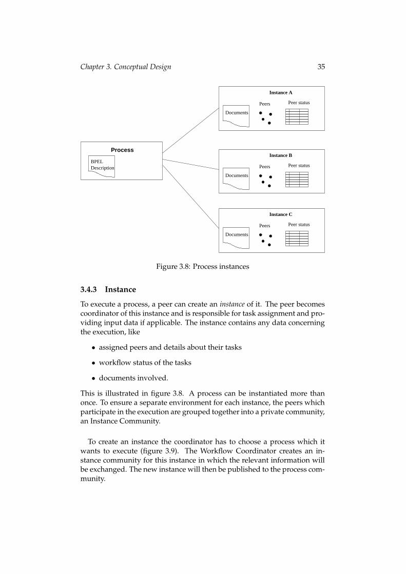
Figure 3.8: Process instances
3.4.3 Instance
To execute a process, a peer can create an instance of it. The peer becomescoordinator of this instance and is responsible for task assignment and pro-viding input data if applicable. The instance contains any data concerningthe execution, like
• assigned peers and details about their tasks
• workflow status of the tasks
• documents involved.
This is illustrated in figure 3.8. A process can be instantiated more thanonce. To ensure a separate environment for each instance, the peers whichparticipate in the execution are grouped together into a private community,an Instance Community.
To create an instance the coordinator has to choose a process which itwants to execute (figure 3.9). The Workflow Coordinator creates an in-stance community for this instance in which the relevant information willbe exchanged. The new instance will then be published to the process com-munity.
Chapter 3. Conceptual Design 36
:Coordinator processCommunity:Community
instanceCommunity:Community
:LocalRepository :User
chooseProcess()
createCommunity()
publish()
store()
Figure 3.9: Create an instances
To execute our AirlineReservation example, the coordinator chooses the pro-cess which has already been added to the corresponding process commu-nity. An instance community is being set up and the required environmentis established.
Chapter 3. Conceptual Design 37
3.5 Quality of Service
In an environment with a large number of peers, we will have a few onesacting as Coordinator Peers and carrying out process executions and thevast majority offering and performing tasks for them. When the Coordina-tor Peer has to carry out the election process, it is likely that he can choosebetween several providers. To be able to make the best decision which peerto assign, the peers have to give quality of service (QoS) attributes for eachtask they publish to the community. The attributes are included in the taskannouncement which is sent to the community and therefore available toall members. Quality of service attributes can be time to execute or price for atask. These attributes don’t have any influence on the quality of the outputdata a task may have to generate.
Chapter 3. Conceptual Design 38
3.6 Data distribution
The distribution of information in our workflow system is subject to ensurelow bandwidth consumption and to avoid sending unnecessary messages.The concept of community which is outlined in the previous chapter helpsto ensure these requirements. The communication between peers is basedon message delivery and the exchange of data files wrapped into MOTIONartifacts.
3.6.1 Messages
Messages are directed notifications from a peer to another peer or a com-munity, implemented as MOTION Messages. They can be targeted to acommunity referring to the group of peers which most probably are inter-ested in this information or it can be sent to a specific peer. Messages havethe function to control the workflow process and to actively distribute in-formation to the peers. Depending on the scope of the message we candistinguish the following types:
Global Messages. These messages are global announcements which aresent to the top level community WFCommunity. We have two messagetypes in this section:
• Create/Remove a Process Community. If a peer decides to create aprocess community, this has to be made public to all members of theworkflow system. The peers then can decide whether they are inter-ested in this field and join the community or they don’t.
• Global search for Task announcements. Peers which are not perma-nently connected to the network have incomplete knowledge of taskannouncements. In offline mode they can’t receive messages and arenot informed about other peers’ tasks. A global search queries allworkflow members whether they offer a specific task and thus getsan actual view of online peers.
Process Community Messages. This message type is sent to process com-munities and informs the peers subscribed to this community. We have onemessage here:
• Provide/Revoke a task announcement. If a peer decides to newlyprovide a task, to change its quality of service attributes, or to stopoffering a task, it informs the community. The members update theirlocal database to keep track of the peers capabilities.
Chapter 3. Conceptual Design 39
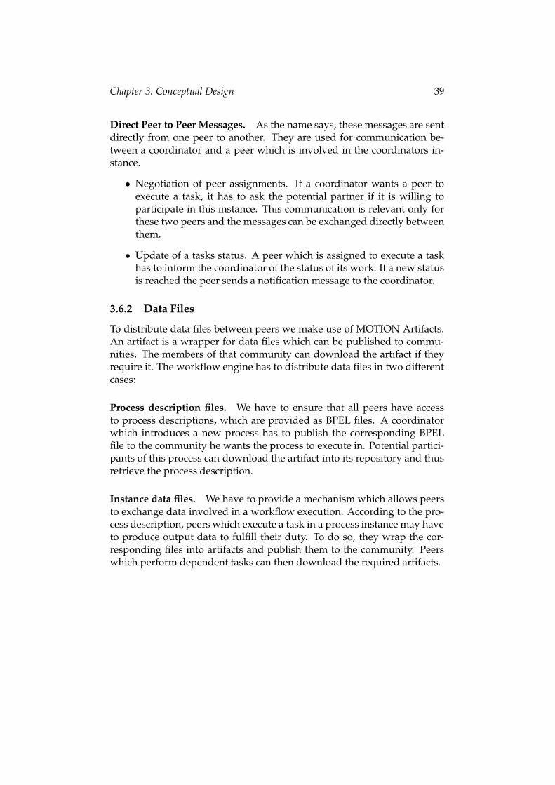
Direct Peer to Peer Messages. As the name says, these messages are sentdirectly from one peer to another. They are used for communication be-tween a coordinator and a peer which is involved in the coordinators in-stance.
• Negotiation of peer assignments. If a coordinator wants a peer toexecute a task, it has to ask the potential partner if it is willing toparticipate in this instance. This communication is relevant only forthese two peers and the messages can be exchanged directly betweenthem.
• Update of a tasks status. A peer which is assigned to execute a taskhas to inform the coordinator of the status of its work. If a new statusis reached the peer sends a notification message to the coordinator.
3.6.2 Data Files
To distribute data files between peers we make use of MOTION Artifacts.An artifact is a wrapper for data files which can be published to commu-nities. The members of that community can download the artifact if theyrequire it. The workflow engine has to distribute data files in two differentcases:
Process description files. We have to ensure that all peers have accessto process descriptions, which are provided as BPEL files. A coordinatorwhich introduces a new process has to publish the corresponding BPELfile to the community he wants the process to execute in. Potential partici-pants of this process can download the artifact into its repository and thusretrieve the process description.
Instance data files. We have to provide a mechanism which allows peersto exchange data involved in a workflow execution. According to the pro-cess description, peers which execute a task in a process instance may haveto produce output data to fulfill their duty. To do so, they wrap the cor-responding files into artifacts and publish them to the community. Peerswhich perform dependent tasks can then download the required artifacts.
Chapter 3. Conceptual Design 40
3.7 Instance lifecycle
As we have seen, process instances are environments for executing pro-cesses. One is created when a coordinator decides to carry out a processand is removed from the workflow system when it is finished and the out-put data is collected. In general we have consecutive five steps in the life ofan instance (figure 3.10):
Create instance Create community Provide input data
Collect ouput dataRemove instance Assign peers
Figure 3.10: Instance lifecycle
1. Create instance. A coordinator invokes the creation by specifying theprocess he wants to be performed.
2. Create community. Automatically an instance community is createdwhich encapsulates the instances messaging and environment.
3. Provide input data. If any data is required for the execution, it has tobe supplied before the tasks can start.
4. Assign peers. For each task a peer has to be assigned which is re-sponsible for performing the specific part of the process.
5. Collect output data. The coordinator collects the output data speci-fied by the process description, which is the result of the overall work.
6. Remove instance. Having successfully received the output docu-ments, the instance and its community are automatically removedfrom the workflow system.
Chapter 3. Conceptual Design 41
3.8 Task status
A task which is published by a Worker Peer can be requested by any Co-ordinator Peer. This starts a negotiation between them and will lead to theexecution of the task, if both of them agree to work together. From thecoordinator’s request to the delivery of the final result by the worker, thetask goes through several stages. Each stage describes the status the taskcurrently is in. A task status is always bound to a Coordinator peer. Thismeans, that a task which is consumed by different Coordinator Peers willhave a separate status for each of them. In Figure 3.11 we have an illustra-tion of this behavior. Consider that a specific peer provides several tasks,including reserveSeats and bookFlight. The figure shows a scenario, wheretwo different coordinators currently have negotiations: The first one is al-ready consuming the task bookFlight and has requested the task reserveSeats.The second coordinator has requested bookFlight.
bookFlight STARTED REQUESTED
Coordinator 1 Coordinator 2
REQUESTEDreserveSeat
StatusTasks
Peer 1
Figure 3.11: Table of peer status
The sequence of all possible status are shown in figure 3.12. The transitionsoccur in the following cases:
1. If a Coordinator Peer wants to consume a task, he has to send a requestto the peer offering it. It is marked as REQUESTED.
2a. The Worker accepts to perform the task the appropriate message. Thestatus now is ACCEPTED.
2b. The Worker is not interested in doing the job and returns a refusal. Thetask is marked as REFUSED and the negotiation is finished.
3a. The Coordinator assigns the Worker and sets the task to ASSIGNED.
3b. It is also possible, that the Coordinator now refuses to assign the taskto a specific peer. This can happen e.g. if he was able to find another
Chapter 3. Conceptual Design 42
one to carry out this part of the process. He informs the Worker of hisdecision and the status turns to REFUSED.
4. When the Worker has all required input documents and doesn’t dependon another peer any more, it immediately starts work and marks thetask as STARTED.
5. Upon finishing the work and delivering any output documents, we havereached the final status FINISHED.
Requested
Refused
Accepted Assigned
Started
Finished
Figure 3.12: Task status
43
Chapter 4
Use cases
The functionality of our workflow system can be divided into three mainparts. The Process Management basically contains methods for handling pro-cess descriptions and communities (figure 4.2). The Task Negotiation dealswith the possible actions from requesting a task to assigning a task (fig-ure 4.3). The Instance Execution part has the functionality of starting andfinishing tasks and instances and management of data flow (figure 4.4).
In our use cases we can distinguish two actors. The Worker Peer acts asa service provider who offers tasks and performs them on demand. TheCoordinator Peer manages processes, creates instances, and elects WorkerPeers which have to execute tasks autonomously.
Process Management Instance Execution
Workflow Engine
Task Negotiation
Figure 4.1: Use case: Workflow System
Chapter 4. Use cases 44
4.1 Process Management
Worker peer
Coordinator peer
load process description
download process description
create process instance
define quality of service attributes
provide task «extends»
«extends»
Process Management
«extends»
create community
add process to community
«extends»
subscribe to community
«extends»
«extends»
remove community
Figure 4.2: Task status
Create community A coordinator can establish a community which willbe the communication platform for a process or a group of related pro-cessed he intends to manage. The name of the new community can bespecified by the user. All members of the workflow system are informedabout the new community and can subscribe it to receive the messages.
Chapter 4. Use cases 45
Remove community A community which is not required anymore can beremoved from the system. The peers are informed about this and removethe references from their local databases. All task announcements of thiscommunity are also removed.
Load process description A new process description which is still un-known to the system can be imported from a file. It has to contain thedescription in BPEL format an must be available on the local file storage.The new process is added to the local repository. The Workflow Coordina-tor also creates an artifact with this file, which can be downloaded by otherpeers.
Add process to a community To make a process visible to other peers, ithas to be added to a process community. Members of this community areinformed about the new process and can retrieve the artifact containing thedescription file.
Create process instance To execute a process a coordinator can create aprocess instance. This will create an instance community which will serveas an environment for communication and document sharing. An instancecan only be created for a process which has been added to a process com-munity.
Download process description A a peer who wants to participate in aworkflow instance and provide a task, needs to have the process descrip-tion available in the local database. If the description is not known to thepeer, he can request an artifact containing the required BPEL documentfrom the coordinator. After the successful download it is imported into thelocal repository.
Provide task A task can be provided to a process community if it is partof a process known to the peer. It is necessary, that the peer has subscribedto that community prior to announcing the task.
Define Quality of Service attributes On providing a task, the peer has togive quality of service attributes which define the terms on which it will becarried out. The attributes help the coordinator to compare announcementsof different peers.
Subscribe to community A peer which wants to become member of aprocess community can subscribe to it. This is necessary to receive anymessages concerning the community, like task announcements.
Chapter 4. Use cases 46
4.2 Task Negotiation
Worker peer
Coordinator peer
accept task
refuse task
search provided tasks
assign task to worker peer
«uses»
«uses»
Task Negotiation
request task from worker peer
«uses»
«extends»
Figure 4.3: Task Negotiation
Search provided tasks The coordinator can actively query all peers of atask he needs. Peers which provide that task re-send an announcement tothe sender. This can be necessary for peers which have been disconnectedfor some time and want to update their local repositories.
Request task from peer If the coordinator wants to give a task of an in-stance to a user, he looks up the database for peers which provide this task.To elect one of them, he can compare the quality of service attributes givenon announcing the task. The coordinator then sends a task request to thespecific peer.
Chapter 4. Use cases 47
Accept task A worker peer which has received a task request has to de-cide whether he wants to accept the task or not. An acceptance sends amessage to the coordinator, indicating that the peer wants to execute thetask.
Refuse task Both worker and coordinator peer have the possibility torefuse a task. The former if he doesn’t want to serve a task and the lat-ter if he admittedly had requested the task, nevertheless doesn’t want toassign that peer.
Assign task If a worker peer has accepted a task request, the coordinatorcan assign him to definitely perform the work. The peer receives the infor-mation concerning the instance community the task is performed in. Hehas to subscribe to the instance community in order to have access to anyrelevant documents.
Chapter 4. Use cases 48
4.3 Instance Execution
Worker Peer
Coordinator Peer
create task output data
start task
finish task
finish instance
«extends»
«extends»
execute task
Instance Execution
«uses»
«uses»
provide instance input data
«uses»
download input data
«extends»
check availability of task input data
«uses»
check completeness of task output data
«uses»
check availability of instance output data
«uses»
retrieve instance output data
«extends»
Figure 4.4: Instance Execution
Provide instance input data The coordinator has to ensure, that theworker peers have access to the input documents, which are required ac-cording to the process description. Before the peers can start the work, thecoordinator has set a document for each input container. The workflow sys-tem wraps the documents into artifacts and publishes them to the instancecommunity where they can be downloaded from.
Check availability of task input data A peer which wants to start to ex-ecute a task has to check, whether it requires any input data. If applicable,
Chapter 4. Use cases 49
the peer has to query the community whether these documents have al-ready been submitted.
Download input data After having successfully checked the availabilityof input data, the artifacts representing the input documents can be down-loaded to the local repository.
Start task As soon as all requirements are met, the worker peer can startthe task. This primarily includes that the task has been assigned to the peerand that all required documents have been downloaded. The coordinatorwill be informed about the new status.
Execute task The worker peer has to perform the work, which is associ-ated with the task. Usually he has to process the input documents and cre-ate output documents as required. The task must have been started priorto the execution.
Create task output data After having created the necessary output doc-uments in the file storage, they have to be made available in the instancecommunity. Similar to the provision of input data, the documents warewrapped into artifacts and published to the instance community.
Check completeness of task output data Before a task can be finished, itmust be ensured that all required output documents have been successfullydelivered. The peer queries the instance community whether all outputcontainers are available.
Finish task Having delivered the output documents and successfullychecked for completeness, the status of the task is set to finished. The peerinforms the coordinator about the successful execution.
Check availability of instance output data The coordinator can checkwhether the output documents have been submitted by the worker peers.He looks up the instance community whether participating peers havepublished the corresponding artifacts.
Retrieve instance output data If the coordinator has successfully checkedthe availability of the documents, he downloads the artifacts representingthe output containers.
Chapter 4. Use cases 50
Finish instance When all peers have fulfilled their tasks and the outputdata is collected, the instance will be set to the final state by the coordinator.The instance community will be deleted as the last step in the execution ofthe process.
51
Chapter 5
Implementation
In this chapter we focus on implementation details of the workflow sys-tem. Based on the design issues discussed in chapter 3, the developmentwas performed using the Java2 platform. The core classes are availablein the package eu.motion.tuv.workflow, integrated in the MOTIONmiddleware.
First we give an overview of the classes and outline the functionality andusage of the most important methods. Then we describe the structure of theprocess description files and will continue with the internal representationof the database files. The next section defines the various message typesthe peer communication relies on. After that we focus on the different pos-sibilities to exchange documents between peers.
5.1 Class diagram
This section gives an overview of the classes of the workflow system. Wewill outline the usage of the most important ones and give a short descrip-tion of attributes and methods. A detailed relationship diagram is shownin figure 5.1.
5.1.1 WFCoordinator
It is the main class in the system and provides an interface for the applica-tion layer. It is responsible for sending messages using the MOTION mid-dleware and gives access to the local database. The methods of this classare non-blocking, as the WFCoordinator doesn’t wait for replies on themessages sent. Incoming messages are trapped and handled by the classWFDatabase.
• The addCommunity()method is used to add a process communityto the system. It creates a community in MOTION with the givenname and sends a message to all peers about the details.
• addTaskToCommunity() publishes a given task or process to acommunity. The members of the community are notified of the newtask announcement.
• On execution of a task, a peer may have to submit output documentsaccording to the process description. The createTaskData()method provides the functionality to assign a document to a specificdata container. The given file is wrapped into a MOTION artifact andsubmitted to the instance community.
Chapter 5. Implementation 53
• getInstanceAdmin() returns the user which is the coordinator ofa given instance.
• The method getRootCommunity() returns the top-level commu-nity WFCommunity, which is mainly used as a target of global mes-sages.
• Given the name of a task, getRootProcess() looks up the processdescription table and returns the process the task is part of.
• If a peer receives a message concerning an unknowntask, he can request the description from the sender usingrequestTaskDescription(). A message is sent to the cor-responding user, asking him to send the corresponding artifact.
• To add a new process description to the system, the importBPEL()method parses the given BPEL-file and adds it to the local database.
• Invoking searchTaskGlobal(), a peer can actively search for allproviders of a specific task.
• The method sendMessage() provides the functionality of sendingmessages using the MOTION middleware. Message type and contentare specified by a WFMessageContent object, which passed as anargument
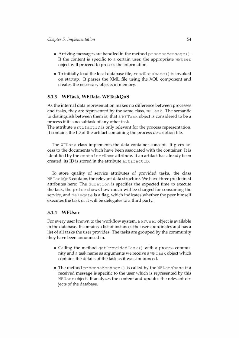
5.1.2 WFDatabase
This class is responsible for the management of users, processes, and in-stances and is accessed by the WFCoordinator class. It provides meth-ods to access the objects which are available in the local database files. Onstartup of the system, it reads the XML database file of the current user andholds the information in memory. To maintain a persistent state of the data,all methods of this class commit the changes to the local storage immedi-ately.The WFDatabase also listens to MOTION messages and processes themupon reception.
• The method commit() writes the database of the current user to apersistent file using the PDOM component.
• Given the name of a task, getTaskDescription() returns the de-scription of the task.
• As this class is registered to receive MOTION messages, theinvoke() method is called whenever a message from another peerarrives. The content is parsed and passed to processMessage().
Chapter 5. Implementation 54
• Arriving messages are handled in the method processMessage().If the content is specific to a certain user, the appropriate WFUserobject will proceed to process the information.
• To initially load the local database file, readDatabase() is invokedon startup. It parses the XML file using the XQL component andcreates the necessary objects in memory.
5.1.3 WFTask, WFData, WFTaskQoS
As the internal data representation makes no difference between processesand tasks, they are represented by the same class, WFTask. The semanticto distinguish between them is, that a WFTask object is considered to be aprocess if it is no subtask of any other task.The attribute artifactID is only relevant for the process representation.It contains the ID of the artifact containing the process description file.
The WFData class implements the data container concept. It gives ac-cess to the documents which have been associated with the container. It isidentified by the containerName attribute. If an artifact has already beencreated, its ID is stored in the attribute artifactID.
To store quality of service attributes of provided tasks, the classWFTaskQoS contains the relevant data structure. We have three predefinedattributes here: The duration is specifies the expected time to executethe task, the price shows how much will be charged for consuming theservice, and delegate is a flag, which indicates whether the peer himselfexecutes the task or it will be delegates to a third party.
5.1.4 WFUser
For every user known to the workflow system, a WFUser object is availablein the database. It contains a list of instances the user coordinates and has alist of all tasks the user provides. The tasks are grouped by the communitythey have been announced in.
• Calling the method getProvidedTask() with a process commu-nity and a task name as arguments we receive a WFTask object whichcontains the details of the task as it was announced.
• The method processMessage() is called by the WFDatabase if areceived message is specific to the user which is represented by thisWFUser object. It analyzes the content and updates the relevant ob-jects of the database.
Chapter 5. Implementation 55
5.1.5 WFInstance
This class contains the relevant information about instances the user is in-volved in. It saves a reference to the instantiated process in the attributemainTask. Other important attributes are information about the commu-nity the process has been published in (processCommunity) and the pri-vate instance community (instanceCommunity).
5.1.6 WFInstanceTask
For each task of the instance the user is involved in, a WFInstanceTaskobject is stored in the database. The input and output containers whichhave to be considered when executing the task are stored in a list of WFDataobjects.
• The method checkOutputData() iterates all output containers andreturns, whether all artifacts have been specified and the task is al-lowed to set its state to finished.
• All input containers are checked with the methodgetMissingData(). If there are input documents missing, itsearches the community for corresponding artifacts and downloadsthem, if available. Otherwise it creates a MOTION subscription withcriteria matching the desired artifact.
5.1.7 WFEventHadler
The class WFEventHandler is an event handler, which listens to subscrip-tions created in the method WFInstanceTask.getMissingData(). Assoon as an artifact has been created which matches the subscription, theprocessEvent() method is invoked. It then automatically downloadsthe desired artifact and updates the WFData object which it refers to.
Chapter 5. Implementation 56
5.2 Process description and BPEL
3
2
4
1
Plan Trip
Submit Order
Receive Itinerary
Receive eTicket
Traveler
Figure 5.2: BPEL example graph
The detailed description of processes have to be provided in an XML filewhich complies with the BPEL specification in [31]. Nevertheless, the re-quirements for our workflow system are not as sophisticated as the com-plete language definition. For that reason we don’t use all BPEL featuresbut work with a limited subset of it.
In this section we will show how the process description is built accord-ing to a graphical representation of the workflow. For simplicity reasonswe have taken some tasks of the total business process as illustrated in fig-ure 5.2. As the the original description doesn’t need any input documents,we have added one to also show this functionality: We assume, that the co-ordinator has to provide a process input document, called catalogue whichthe traveler requires to start planning the trip. This is indicated by an arcdenoted as (2) in the illustration.The process description in BPEL notation which we refer to in the nextparagraphs is shown in the listing in figure 5.3. As this is not the completefile, we use dots (...) as a placeholder for missing parts.
Chapter 5. Implementation 57
5.2.1 Structure
A BPEL definition consists of three major sections,<partners>,<containers>,and<flow>.The first two are declarativeand describe roles and objects, and the third one gives the tasks andrelations between them.
Partners, line 2-6.
This section defines the different parties which interact with the businessprocess when it is executed. The three partners shown here correspond tothe person who wants to have his trip planned (traveler), as well as the agentwhich processes his request, and an airline which does the actual flight andseat reservation. The workflow graph shows the partners in the top section,denoted with (1). In practice, a partner role defines a set of tasks whichreasonably will be performed by one person or peer. For example, in aninstance of our airline reservation process, there will practically only be onepeer which performs the tasks Plan Trip, Submit Order, Receive Itinerary, andReceive Ticket. Anyway, as the semantical context is considered out of scopein our workflow system, we ignore any influence of the partners definitionon the execution course of a business process.
Containers, line 8-13.
This declaration defines the containers which serve for data exchange be-tween the tasks and give access to process input and output documents.The different containers, which are necessary throughout a process execu-tion, have to be identified during the requirement analysis of the businessprocess. Containers have also the function of determining dependenciesbetween the tasks. We define, that a task B is dependent on a task A, iftask A stores documents into a container which are required for task B’sexecution.
Flows, line 16-45.
In the third part of the process definition we have the actual task defini-tions. This includes information about how they are linked together andwhich containers are passed between them. To comply with all kinds ofdocument flows we have to deal with, we have to distinguish betweenthree flow types which are identified as follows:
• Process input data. A process input document which has to be pro-vided by the coordinator is denoted with (2) in figure 5.2. The im-plementation in BPEL is done with a <receive> node (line 17-20).Here, the documents have to be provided in the container catalogue.
Chapter 5. Implementation 58
• Task. The tasks of the process are represented by <invoke> nodes,with the task name given in the operation attribute. The input andoutput documents are described in the attributes inputContainerand outputContainer respectively. Arcs, which point from oneoperation to another and thus show a connection between them, aremapped to links: For example, the tail of the arc number (3) is repre-sented by a link source in line number 25, and the the head of that arcis connected to the task Submit Order by a link target in line number32, both identified by the arc’s name planTrip-ready.
• Process output data. A process can be considered as finished, whenall output containers are provided. In our example this is done, whenthe traveler has received his tickets, denoted as (4) in the illustration.The coordinator can then retrieve the documents. The lines 39-41 inthe BPEL file show the <reply> node which delivers the containerissuedTickets to the coordinator.
Figure 5.3: BPEL definition of the airline process
Chapter 5. Implementation 60
5.3 Internal database format
The local data storage of the peers is implemented using PDOM and XQL[38]. The database contains any information which is relevant for processmanagement, as well as messages received from and sent to other peers.Every peer has its own database which gives the peer’s local view of theworkflow engine. This section will give an overview of the data structurewhich is listed in figure 5.4.
The content of the database has three main data sections (line 3). The<Description>node contains process definitions which have either beenimported or downloaded, and the <User> nodes contain any informationreceived from and sent to a specific peer. The <KnownCommunity> nodeslist all communities known to the peer.
Description node. All tasks known to a peer are stored as <Task> nodeshere (line 8-9). This includes default values for quality of service attributesand the definition of flow data, which is referred to as container in BPELnotation.
User nodes. The user nodes (line 27) represent the knowledge base ofthe communication with other peers. It contains task announcements anddetails about participations in process instances. Every peer which hada message delivered to the owner of the database is represented with a<User>node. Furthermore the owner of the data storage himself has node,containing its own announcements and participations.
• The <Provide> node (line 30) contains all tasks which are providedby the specific peer, grouped by the community they have been an-nounced in.
• The most important nodes for process executions are the<WorkUnits> (line 35): All instances a peer is involved in arelisted here. In more detail, the <InstanceTask> subnodes (line 43)describe the messaging which has taken place in this context. Theexchange of documents which has taken place between the partici-pants of the instance is also tracked in this subtree. Containers whichhave already been provided to the specific instance are representedby the artifact, stored in the <WFData> child nodes.
KnownCommunity nodes. All communities, which have been added tothe workflow system are listed here. This does not include instance com-munities, which are only visible to participants of the specific instances.
1011 <!ELEMENT Subtask>12 <!ATTLIST Subtask CDATA name #REQUIRED>1314 <!ELEMENT FlowData (Comment)>15 <!ATTLIST FlowData name CDATA #REQUIRED>16 <!ATTLIST FlowData type CDATA #REQUIRED>17 <!ATTLIST FlowData artifact CDATA #IMPLIED>1819 <!ELEMENT Comment (#PCDATA)>2021 <!ELEMENT QoS (duration,price,delegate)>2223 <!ELEMENT duration (#PCDATA)>24 <!ELEMENT price (#PCDATA)>25 <!ELEMENT delegate (#PCDATA)>2627 <!ELEMENT User (Provide, WorkUnits)>28 <!ATTLIST User id CDATA #REQUIRED>2930 <!ELEMENT Provide (Community*)>3132 <!ELEMENT Community (Task*)>33 <!ATTLIST Community id CDATA #REQUIRED>3435 <!ELEMENT WorkUnits (Instance*)>3637 <!ELEMENT Instance (InstanceTask+)>38 <!ATTLIST Instance id CDATA #REQUIRED>39 <!ATTLIST Instance mainTask CDATA #REQUIRED>40 <!ATTLIST Instance processCommunity CDATA #REQUIRED>41 <!ATTLIST Instance instanceCommunity CDATA #REQUIRED>4243 <!ELEMENT InstanceTask (Message*, FlowData*)44 <!ATTLIST Instance taskName CDATA #REQUIRED>45 <!ATTLIST Instance processCommunity CDATA #REQUIRED>46 <!ATTLIST Instance instanceCommunity CDATA #REQUIRED>4748 <!ELEMENT Message>49 <!ATTLIST Message date CDATA #REQUIRED>50 <!ATTLIST Message received CDATA #REQUIRED>51 <!ATTLIST Message user CDATA #REQUIRED>52 <!ATTLIST Message type CDATA #REQUIRED>5354 <!ELEMENT KnownCommunity>55 <!ATTLIST KnownCommunity id CDATA #REQUIRED>56 <!ATTLIST KnownCommunity name CDATA #REQUIRED>5758 ]>
� �
Figure 5.4: DTD of local database
Chapter 5. Implementation 62
5.4 Peer messaging
The exchange of information between the participants of the workflow sys-tem is mostly performed using messages. This communication is imple-mented using MOTION messages. They can be targeted to a specific peeror a community, respectively. In our implementation both mechanisms areused, depending on the requirements of the information being transmitted.
5.4.1 Announce a new community
Message WF_NEW_COMMUNITYTarget WFCommunity
Parameterid: MOTION id of the new communityname: Name of the new community
Description When a user creates a new Process Community, he has toinput a name for it. The Workflow Coordinator then cre-ates a MOTION Community and receives a unique id. Themessage containing both the name and the id is sent to theWFCommunity and delivered to all peers. The recipientsautomatically add the information to their local database.
5.4.2 Remove a community
Message WF_REMOVE_COMMUNITYTarget WFCommunityParameter id: MOTION id of the communityDescription If a user decides to remove a Process Community, all peers
have to be informed immediately. The chosen communityis removed from the middleware and a message containingthe id is sent to the WFCommunity. The peers automaticallyremove the community from their databases. This of courseimplies, that any task announcements of this communitybecomes invalid and is removed as well.
Chapter 5. Implementation 63
5.4.3 Global search for a task
Message WF_SEARCH_TASKTarget WFCommunityParameter taskName: Name of the task to searchDescription The WF SEARCH TASK message is the only message which
actively queries other peers whether they provide a task.The content includes the name of the desired task. Peerswhich receive this message look up their own databasesif they have announced the given task in any community.If one currently provides the task, it replies to the senderwith a WF PROVIDE TASKmessage, containing the relevantdetails. As this method of querying for announcements israther expensive in terms of bandwidth use, it should notbe used frequently. It is meant to update a peers databasewhen reconnecting to the workflow system after a longtime.
5.4.4 Announce a task
Message WF_PROVIDE_TASKTarget Process Community
ParametertaskName: Name of the taskprocessCommunityId: Community the task is published inqos: Quality of Service attributes
Description If a peer wants to provide a task, it has to choose a task, se-lect the Process Community, and specify the Quality of Ser-vice attributes. This information is included in the messageand transmitted to the subscribers of the chosen commu-nity. The recipients have to update their local databases. Ifa peer finds that the sender has published this task before,it removes the old announcement and replaces it with thenew one. This results in an update of the Quality of Serviceattributes.
Chapter 5. Implementation 64
5.4.5 Revoke a task announcement
Message WF_UNPROVIDE_TASKTarget Process Community
Parameter taskName: Name of the taskprocessCommunityId: Community of the task
Description To revoke a task announcement a peer uses this message.The former announcement is identified by the name of thetask (taskName) and the Process Community the task waspublished in (processCommunityId). The recipients of thismessage query their databases and remove the relevant en-tries if existent.
5.4.6 Request the process description for a task
Message WF_GET_TASK_DESCTarget PeerParameter taskName: Name of the taskDescription A peer which receives an announcement of a task it has
no information of in its database, it can request the processdescription file for this task. The message is transmitted tothe sender of the task announcement with the taskName asargument. When a peer receives this request it looks up itsdatabase which process it concerns and replies the relevantinformation using a WF SEND TASK DESC message.
5.4.7 Send process description
Message WF_SEND_TASK_DESCTarget PeerParameter artifactUri: Artifact URI of the process description fileDescription This message is a reply on a WF GET TASK DESC request
and includes the resource identifier (artifactUri) for a MO-TION artifact which contains the process description file.The receiver of such a message automatically downloadsthe artifact from the given URI and imports the process de-scription file into its database. The URI itself will also bestored in order to being able to serve requests from otherpeers. The download is illustrated in figure 3.5.
Chapter 5. Implementation 65
5.4.8 Request a task
Message WF_REQUESTTarget Peer
Parameter
taskName: Name of the taskinstanceId: id of the process instanceprocessCommunityId: id of the Process CommunityinstanceCommunityId: id of the Instance Community
Description This message is sent to ask a peer whether it wants to exe-cute the given task. The parameters taskName and process-CommunityId are used by the recipient to identify the spe-cific task the sender refers to. This is important, because thepeer can have announced a task in several Process Com-munities with different Quality of Service attributes. Theparameters instanceId and instanceCommunityId refer to theprocess instance the task should be performed in. The re-quest is added to the local database and marked as a newmessage, but no further action is taken.
5.4.9 Accept a task request
Message WF_REPLY_ACCEPTTarget Peer
ParametertaskName: Name of the taskinstanceId: id of the process instanceprocessCommunityId: id of the Process Community
Description To reply to a WF REQUEST message and inform the senderthat the task is ready to be executed, a peer has to send thismessage. The parameters included help the requesting peerto match the reply to his prior message.
5.4.10 Refuse a task request
Message WF_REPLY_REFUSETarget Peer
ParametertaskName: Name of the taskinstanceId: id of the process instanceprocessCommunityId: id of the Process Community
Description This message can be sent in two different cases: (a) a peerwhich receives a WF REQUESTmessage doesn’t want to per-form the task, or (b) a requesting peer gets a positive an-swer but decides at this point of the negotiation that it willnot entrust it with this work. The parameters included helpthe requesting peer to match the reply to its prior message.
Chapter 5. Implementation 66
5.4.11 Assign a task to a peer
Message WF_ASSIGNTarget Peer
Parameter
taskName: Name of the taskinstanceId: id of the process instanceprocessCommunityId: id of the Process CommunityinstanceCommunityId: id of the Instance Community
Description This message informs a peer to actually perform the task.Upon reception of this notification the peer has to subscribeto the instance community identified by the parameter in-stanceCommunityId in order to receive all messages concern-ing the instance.
5.4.12 Start execution of a task
Message WF_REPLY_STARTTarget Peer
Parameter
taskName: Name of the taskinstanceId: id of the process instanceprocessCommunityId: id of the Process CommunityinstanceCommunityId: id of the Instance Community
Description This message informs the coordinator that all requirements(e.g. availability of input data) have been met to startthe task. The coordinator stores this information into itsdatabase but doesn’t take any further action. The purposeof this notification is to keep track of the current instancestatus.
5.4.13 Finish execution of a task
Message WF_REPLY_FINISHTarget Peer
ParametertaskName: Name of the taskinstanceId: id of the process instanceprocessCommunityId: id of the Process Community
Description This message informs the coordinator that the task identi-fied by the parameter has been successfully finished. Thecoordinator updates its database and checks the overall in-stance status. If every single task is finished, the outputdata can be retrieved by the coordinator.
Chapter 5. Implementation 67
5.5 Exchange of documents
Besides communicating using messages, the workflow system requires amethod to exchange data files. The MOTION middleware supports us withthe artifact concept which provides a mechanism to share files among dif-ferent peers. An artifact represents an object which can be published to acommunity. It is then visible to all members of that community and can bequeried by other peers using meta information which is attached to the ar-tifact. We have to consider two document types which have to be retrieveddifferently: Process description files and instance documents.
5.5.1 Process description files
A peer which wants to download a process description file has to requestit from the coordinator using messages (see section 5.4). A successful re-ply contains the URI of the desired file. Using the MOTION middlewarethe document identified by the URI can be downloaded. These steps areillustrated in figure 5.5.
:MOTION :Peer :WFCoordinator
requestFile(URI)
requestFile(URI)
return(file)
sendLocation(URI)
requestProcessDescription(taskName)
Figure 5.5: Download a process description from another peer
Chapter 5. Implementation 68
5.5.2 Instance documents
During instance execution peers may have to produce output data to fulfilla task they are assigned to perform. These files have to be added to theworkflow engine that other peers, which require this information, can re-trieve it. Which documents are involved in a task is specified in the datacontainer definition of the process description. The document of a datacontainer will be stored as an artifact as soon as it becomes available. Itwill be added to the corresponding instance community for other peers tofind it.
In order to being able to identify an artifact, we need a matching betweenartifacts and data container. This is established using the NAME attribute ofthe artifact, which contains the name of the corresponding data container.When a peer needs a specific artifact, it can look up the list of artifacts ofthe instance community and match the NAME attribute with the name of thedata container which it desires.
Chapter 5. Implementation 69
Deliver a document for an instance task
To deliver a document, a user has to choose an instance, and a task whichhe is assigned to perform, and the data container he wants to submit. Fur-thermore a file has to be chosen which contains the data of interest. TheWFCoordinator then will create an artifact for the given file and set thename according to the data container. The artifact is added to the instancecommunity and the data container in the local database is updated with theid of the artifact (see figure 5.6).
The same steps apply when a coordinator wants to execute an instancewhich, according to the process description, requires some input data.
:WFCoordinator :MOTION :WFDatabase
createTaskData(task,instance,container,filename)
createArtifact(filename)
artifactID
:User
choose task and instance
choose data container
get data container(task)
list of containers
setName(container)
getCommunity(instance)
community
addArtifactToCommunity(artifactID,community)
store(artifactID)
return(ok)
Figure 5.6: Deliver a document for an instance task
Chapter 5. Implementation 70
Retrieve documents of an instance task
When a peer wants to start the execution of a task, it has to ensure that allinput data the task depends on is available in the instance community. Todo so, the peer looks up the process description for all data containers ofthe corresponding task. For each the Workflow Coordinator searches forartifacts in the community, matching the NAME attribute with the specificcontainer name. If it is not available, which means that the desired docu-ment has not been submitted to the community, the workflow coordinatorautomatically subscribes on this search criteria. As soon as any peer createsthe desired artifact, a notification is fired which causes the workflow coor-dinator to retrieve the artifact. Using the included URI the document canbe downloaded from the corresponding peer. A detailed sequence of thesesteps are outlined in figure 5.7.
When a coordinator executes an instance which as a result has outputdata, he can retrieve the documents the same way as described here.
Chapter 5. Implementation 71
:WFCoordinator :MOTION :WFDatabase
getTaskData(instance,task)
:User
choose task and instance
get data container(task)
list of containers
getCommunity(instance)
community
return(ok)
searchArtifact(community,name=container)
[artifact not available]
foreach container
return(null)
subscribe(community,name=container)
:Peer
addArtifact
notify()
getArtifact(id)
return(artifact)
extractURI(artifact)
requestFile(URI)
requestFile(URI)
return(file)
Figure 5.7: Retrieve documents of an instance task
72
Chapter 6
Validation
In this chapter we want to show, how the functionality of the workflowsystem has been integrated into a graphical user interface. The GUI is anextension of the the Java MOTION client and introduces three modules:
• The Process Manager basically supplies us with the functionality ofcommunity management, handling of process descriptions, and pro-viding tasks.
• The User Manager shows the current view of all known users and pro-vided tasks and contains the process description download.
• In the Instance Overview task negotiations and instance executionstake place. Furthermore, it has a sub-module Instance Manager whichthe coordinator can use to supervise and coordinate instances.
Taking into account our airline reservation case study, the next sectionsshow various steps of process management issues and the execution of aninstance. We have two peers involved, one acting as the coordinator (username admin) and the other acting as a worker (user name data).
Chapter 6. Validation 73
6.1 Process Management
This section describes the steps which are necessary to set up an environ-ment for the execution of a process. The coordinator peer is responsible forcreating a community, adding a process to the workflow system, addingthe process to the newly created community and creating an instance forthe process. The worker peer which participate in this workflow has tojoin the specific process community. Then he can download the processdescription and choose tasks which he provides for execution. Figure 6.1gives an overview of these steps.
Coordinator Peer Workflow System Worker Peer
input name
addCommunity(name)
select BPEL file
addProcess(BPEL file) select community
subscribeCommunity(community)
Figure 6.2
Figure 6.3
Figure 6.6
select process
select community
addProcess(process,community)
Figure 6.4
select process
downloadProcess(process)
Figure 6.7 select process
select community
addInstance(process,community)
select task
enter QoS
provideTask(task,community,QoS)
select community Figure 6.8
Figure 6.5
notify()
notify()
notify()
Figure 6.1: Process Management overview
Chapter 6. Validation 74
6.1.1 Coordinator: Add a community
The creation of a community takes place in the Workflow Process Manager.On choosing the appropriate menu item, the user is asked for the new com-munity’s name. The new community is then visible to all users of the net-work.
Figure 6.2: Add a community
Chapter 6. Validation 75
6.1.2 Coordinator: Add process description
To import a process description to the workflow system we need to load itfrom a local file in BPEL-format. The process with all tasks will be shownin the Workflow Process Manager next to the available communities.
Figure 6.3: Add process description
Chapter 6. Validation 76
6.1.3 Coordinator: Add process to a community
So far, the description is only available locally. To make it accessible to otherpeers, we have to publish it to a process community. This is performed inthe Workflow Process Manager using a copy and paste concept. We highlightthe airline process and click the Copy button in the toolbar. Then wemark the AirlineCommunity and use the Paste button to publish it to theselected community.
Figure 6.4: Add a process to a community
Chapter 6. Validation 77
6.1.4 Coordinator: Create a process instance
To create an instance and set up an environment for the execution, we haveto highlight the airline process and choose the appropriate item fromthe context menu. The details of the instance can be seen in the InstanceManager which will be shown in the next section.
Figure 6.5: Create an instance
6.1.5 Worker: Subscribe to a process community
After the coordinator has created a process community, it is visibleto any connected peer. To receive the communication concerning theAirlineCommunity the worker peer subscribes to the community.
Figure 6.6: Subscribe a process community
Chapter 6. Validation 78
6.1.6 Worker: Download process description
In order to take part in the airline reservation process, the worker peerhas to receive the description of the process. This can be done using theWorkflow User Manager. The desired process airline is available in theAirlineCommunity in the subtree of the coordinator user, named admin.After having downloaded the description file, it will be added to the localrepository and is visible in the Workflow Process Manager.
Figure 6.7: Download process description
Chapter 6. Validation 79
6.1.7 Worker: Provide a task
To offer a task for execution, the worker has to use the Workflow Pro-cess Manager interface. We want to provide the task planTrip to theAirlineCommunity. After highlighting the appropriate task and usingthe Copy button we select the community it should be provided in and usethe Paste button to proceed. Now the user is asked to specify the Quality ofService attributes. On confirmation the task is published to the communitywith the specified attributes and visible to the other peers.
Figure 6.8: Provide a task
Chapter 6. Validation 80
6.2 Task negotiation
In this section we will show how the coordinator looks for task providershe requires for the execution of the airline instance. It shows the com-munication with the worker peer which takes place until a task assignmentis achieved. In figure 6.9 we have an overview of the steps performed.
Coordinator Peer Workflow System Worker Peer
select instance/task
requestTask(task,user)
acceptTask(task)
Figure 6.12
Figure 6.11
Figure 6.13
select user
select instance/task
assignTask(task,user)
select user
select instance/task
notify()
notify()
Figure 6.9: Task Negotiation overview
Chapter 6. Validation 81
6.2.1 Coordinator: Request a task
After having created an instance the coordinator can proceed to the InstanceOverview. This window gives an overview of all instances the peer is in-volved, both acting as coordinator or as worker peer. In our example theonly instance shown is the previously created instance of the flight reser-vation scenario. To view the details and coordinate the tasks, the user canchoose Manage Instance from the context menu.
Figure 6.10: Instance coordination
The Instance Management window gives a detailed view of the tasks of theprocess. Choosing a specific task in the tree lists all peers which providethis task or which are already in negotiation with the coordinator. In ourscenario we have one peer (data) which provides the task planTripwiththe Quality of Service attributes listed. The coordinator can now invite thepeer to execute the task with sending a Request message.
Figure 6.11: Request task
Chapter 6. Validation 82
6.2.2 Worker: Accept a task
The worker can use the Instance overview window to negotiate with the co-ordinator. He has to choose the task planTrip to see all instances he is in-volved in and notices that the coordinator has sent a Request notification.He can decide whether to accept or refuse the execution with replying theappropriate status message. In this case the worker proceeds with sendingan Accept message.
Figure 6.12: Accept task
Chapter 6. Validation 83
6.2.3 Coordinator: Assign a task to a worker peer
The coordinator can see the latest status of the negotiation in the InstanceManagement window. To assign the task, which has been accepted by thepeer, he sends another message indicating the new status Accepted.
Figure 6.13: Assign task
Figure 6.14: Task assignment complete
Chapter 6. Validation 84
6.3 Instance execution without input data
In this section we show the steps which have to be performed by the workerpeer to execute the task planTrip. According to the process descriptionwe don’t require any input documents here. The handling of input data isshown in the next section.
Coordinator Peer Workflow System Worker Peer
startTask(instance,task)
Figure 6.17 select instance/task
notify()
notify()
submitData(instance,task)
perform work
Figure 6.18
finishTask(instance,task) Figure 6.19
notify()
Figure 6.15: Instance execution overview 1
Chapter 6. Validation 85
6.3.1 Worker: Start task
The worker is notified in the Instance Overview window about the task as-signment. He can now open the Input/Output data dialog to have a lookwhether planTrip requires any input documents to start. As the taskdoesn’t need any input data we have an empty list and it can be startedimmediately with the button Start. The coordinator is informed about thenew status with an appropriate message.
Figure 6.16: Open the Data I/O window
Figure 6.17: Start task
Chapter 6. Validation 86
6.3.2 Worker: Execute and finish task
After the worker has started the task, he has any information he requiresto actually perform the work. The result usually consists of one or moredocuments which have to be submitted to the community. To deliver thedocuments, if applicable, he has to use the Input/Output data dialog. In theoutput tab all required data containers are listed. For each the user has tochoose a file which contains the relevant information and then create anartifact. It will be associated with the task and submitted to the instancecommunity. In this scenario a container locationsAndDate has to beconsidered.
Figure 6.18: Submit task output data
Chapter 6. Validation 87
Having defined all containers, the user has to click on the button Submitoutput data. This validates that all artifacts have been submitted. In positivecase the task is finished and a message is sent to the coordinator indicatingthe new status. Otherwise the user is informed about missing documents.
Figure 6.19: Finish task
The coordinator peer is able to track the last steps the worker has per-formed. In his view of the Instance Management window he can monitorthe status transitions. After the worker has finished the task planTrip,the coordinator has the following information of the instance:
Figure 6.20: Task completed
Chapter 6. Validation 88
6.4 Instance execution with input data
To demonstrate the execution of a task which requires input data from an-other peer, we assume that the following steps already have taken place:
• A peer has subscribed to the AirlineCommunity and has down-loaded the airline process description
• It then has provided the task submitOrder to the community.
• The coordinator and the peer have successfully negotiated and thetask has been assigned.
Considering these steps, the current status of the task submitOrder in thecoordinators Instance Management view is shown below:
Figure 6.21: Assignment of task submitOrder
Chapter 6. Validation 89
The worker peer now is prepared to execute the task. In the InstanceOverview window he opens the Input/Output data dialog to check the re-quired documents.
Figure 6.22: Open the Data I/O window
The Input/Output data dialog shows one entry in the input tab. The con-tainer locationsAndDate is an required input document which has to beretrieved from the instance community. With a click on the button Get inputdata the workflow system tries to download the corresponding artifact tothe local fire storage. If this succeeds, the task is automatically started anda notification of the new status is sent to the coordinator. The details of theartifact are shown for the highlighted container.
Figure 6.23: Receive input data
Chapter 6. Validation 90
The Instance Management view of the coordinator now shows the newlyreceived status Started.
Figure 6.24: Start of task receiveOrder
Chapter 6. Validation 91
6.5 Retrieve instance output documents
When all tasks are finished, the coordinator can retrieve the output doc-uments from the instance community. He can start the Input/Output datafrom the toolbar of the Instance Management dialog and use it similarly tothe worker peers. The difference is, that the coordinator submits inputdata to the instance and receives output data, whereas the worker peersreceive input data and submit output data. In our example we have oneoutput document which is to be received by the coordinator. The containerissuedTickets is shown in the output list. With the button Receive outputdata the artifact is downloaded to the local repository, if available.
Figure 6.25: Download instance output data
92
Chapter 7
Conclusion and outlook
This thesis described a peer-to-peer workflow system targeting on the man-agement of human workflow processes. The main elements of the architec-ture, i.e. the process management, the task negotiation, and the instanceexecution were presented and a flight reservation case study was used todemonstrate the main principles of the approach.
Peer-to-peer computing is currently expected to be a major revolution incomputing, as big as the PC was in 1980s. In addition, inter-organizationalworkflow is becoming a main paradigm for distributed system implemen-tation. Furthermore the rapid growth of Internet-ready mobile devices re-quires contribution to slim clients and limited bandwidth. Together, thethree paradigms can provide the essential infrastructure for executing dy-namic workflow processes over the Internet. Such workflows are adaptive(the flow of work is dynamic and is controlled by the peers) and easilyscalable (i.e. by altering the number of participating peers).
Another benefit of the proposed approach is its flexibility: in a conven-tional static workflow system bottlenecks can occur when one of the pro-cess participants becomes unavailable. In contrast, in the peer-to-peer ap-proach, tasks are quickly re-assigned to one of the available peers.
The discussed flight reservation case study where all peers can be as-sumed to be known and trusted, does not pose significant problems com-pared to general business workflow applications where trust, security, in-tegrity and confidentiality are going to be of high importance. Further re-search is therefore required in areas such as data encryption, security andintegrity of the workflow transactions. Such research includes documentencryption to keep confidential information private and digital signaturesto provide authenticity and integrity.
Chapter 7. Conclusion and outlook 93
Further studies are required in providing meta-information along withprocess descriptions. A detailed textual and graphical description of thetasks and its dependencies is indispensable, including a definition of in-volved documents as regards content.
The quality of service attributes are also subject to further improvements.In addition to attributes like price or duration as introduced in this imple-mentation, the system can supply the participants with statistically gen-erated quality criteria. Another approach would be a rating functionalitywhich allows process coordinators to value the quality of consumed tasks,serving others as a decision basis for peer assignment.
[1] John Schlesinger. What is Workflow? Business Integration Journal,March 2004, pp 40-44.http://www.bijonline.com/PDF/schlesinger%20march.pdf
[2] Prof.Dr.Frank Leymann. Work Service Flow Language Specification,May 2001.http://www-4.ibm.com/software/solutions/webservices/pdf/WSFL.pdf
[3] A Peer-to-Peer Middleware.http://peerware.sourceforge.net.
[4] Carlo Ghezzi, Gianpaolo Cugola, and Gian Pietro Picco. A Peer-to-PeerMiddleware for Mobile TeamWork.http://www.ercim.org/publication/Ercim News/enw54/cugola.html.
[5] Amy L. Murphy, Gian Pietro Picco, and Gruia-Catalin Roman. LIME:A Coordination Middleware Supporting Mobility of Hosts and Agents,April 17, 2003.http://www.elet.polimi.it/upload/picco/papers/formalLime.pdf
[6] Java Technology, Sun Microsystems, Inc.http://java.sun.com
[7] Gerald Reif, Engin Kirda, Harald Gall, Gian Pietro Piccoz, GianpaoloCugolaz, Pascal Fenkam. A Web-based Peer-to-Peer Architecture forCollaborative Nomadic Working.http://peerware.sourceforge.net/papers/wetice2001.pdf.
[8] Gianpaolo Cugola, Carlo Ghezzi, Mattia Monga, Harald Gall, MehdiJazayeri, Engin Kirda. Information Distribution Requirements and MO-TION Architectural Principles, WP2 / Task2.1 July 30, 2000.
[9] Microsoft Visual C#, Microsoft Corporation.http://msdn.microsoft.com/vcsharp
[10] Microsoft .NET, Microsoft Corporation.http://www.microsoft.com/net
Bibliography 97
[11] Mattia Monga. Supporting nomadic co-workers: an experience with apeer-to-peer configuration management tool.http://homes.dico.unimi.it/monga/lib/pbit2003.pdf
[13] D. Hollinsworth. The Workflow Reference Model. Technical ReportTC00-1003, Workflow Management Coalition, December 1994.
[14] B. Reinwald. Workflow Management in verteilten Systemen. Teubner-Texte zur Informatik. B.G. Teubner Verlagsgesellschaft, Stuttgart,Leipzig, 1993.
[15] D. Georgakopoulos, M. Hornick, A. Sheth. An Overview of WorkflowManagement: From Process Modeling to Workflow Automation Infras-tructure. Distributed and Parallel Databases, Kluwer Academic Publish-ers, September 1994.
[16] World Wide Web consortium.http://www.w3c.org
[17] XHTML 1.0 The Extensible HyperText Markup Language (SecondEdition). A Reformulation of HTML 4 in XML 1.0. W3C Recommenda-tion, 26 january 2000, revised 1 August 2002.http://www.w3.org/TR/2002/REC-xhtml1-20020801
[18] JXTA Technology: Creating Connected Communities.http://www.jxta.org/project/www/docs/JXTA-Exec-Brief.pdf, January 2004.
[19] Sun Microsystems.http://www.sun.com
[20] M. Corson, J. Macker, G. Cinciarone. Internet-Based Mobile Ad HocNetworking.IEEE Internet Computing, vol. 3, no. 4, 1999
[21] T. Dierks, C. Allen. The TLS Protocol Version 1.0. Memo RFC 2246,January 1999.ftp://ftp.ietf.org/rfc/rfc2246.txt
[22] Georgios John Fakas, Bill Karakostas. A peer to peer (P2P) architecturefor dynamic workflow management. Information and Software Technol-ogy Journal, 2003.
[23] KaZaa, The KaZaa Web Site, http://www.kazaa.com
Bibliography 98
[24] Zhiyong Xu, Yiming Hu. SBARC: A Supernode Based Peer-to-PeerFile Sharing System.http://www.ececs.uc.edu/∼oscar/papers/zyxu sbarc.pdf
[25] Gnutella, The Gnutella Web Site, http://www.gnutella.com
[26] Anurag Sigla, Christopher Rohrs, Lime Wire LLC. Ultrapeers: An-other Step Towards Gnutella Scalability, Version 1.0. 26 November 2002http://rfc-gnutella.sourceforge.net/src/Ultrapeers 1.0.html
[27] UDDI, The UDDI Web Site, http://www.uddi.org
[28] Ingrid Wetzl, Ralf Klischewski. Serviceflow beyond workflow? IT sup-port for managing inter-organizational service processes, InformationSystems 29 (2), April 2004, pp. 127-145, 2004.
[29] R. Klischewski, I. Wetzel, A. Bahrami. Modeling serviceflow, in: In-formation Systems Technology and its Applications, Proceedings ISTA2001, German Informatics Society, Bonn, 2001, pp. 261-272.
[30] W.M.P. van der Aalst, Process-oriented architectures for electroniccommerce and interorganizational workflow, Information Systems 24 (8)(2000) 639-671.
[31] Francisco Cubera, Yaron Goland, Johannes Klein et al. BusinessProcess Execution Language for Web Services, August 2002.http://msdn.microsoft.com/library/default.asp?url=/library/en-us/dnbizspec/html/bpel1-0.asp
[32] Keith Mantell. From UML to BPEL, September 9, 2003.http://www-106.ibm.com/developerworks/webservices/library/ws-uml2bpel
[33] Erik Christensen, Francisco Curbera, Greg Meredith, Sanjiva Weer-awarana. Web Services Description Language (WSDL) 1.1. W3C Note,March 15, 2001.http://www.w3.org/TR/wsdl
[34] David C. Fallside. XML Schema Part 0: Primer. W3C Recommenda-tion, 2 May 2001.http://www.w3.org/TR/2001/REC-xmlschema-0-20010502
[35] Henry S. Thompson, David Beech, Murray Maloney, Noah Mendel-sohn. XML Schema Part 1: Structures. W3C Recommendation 2 May2001.http://www.w3.org/TR/2001/REC-xmlschema-1-20010502
[36] Paul V. Biron, Ashok Malhotra. XML Schema Part 2: Datatypes. W3CRecommendation, 2 May 2001.http://www.w3.org/TR/2001/REC-xmlschema-2-20010502
Bibliography 99
[37] James Clark, Steve DeRose. XML Path Language (XPath) Version 1.0.W3C Recommendation, 16 November 1999.http://www.w3.org/TR/1999/REC-xpath-19991116
[38] DOM and XQL Engine, the XML Data Server - Components for Data-Intensive XML Applications. Thomas Klement, Fraunhofer’s IntegratedPublication and Information Systems Institute IPSI, 2002.http://www.ipsi.fraunhofer.de/oasys/projects/pdom/pdome.html
[39] Lauren Wood, Arnaud Le Hors et al. Document Object Model (DOM)Level 1 Specification (Second Edition) Version 1. W3C Working Draft, 29September 2000.http://www.w3.org/TR/2000/WD-DOM-Level-1-20000929/