Summary: Energy absorbing foam padding is widely applied in various areas of modern cars in conjunction with increasing number of airbags as passive safety systems. High efficient energy absorbing foams which can be used to optimise energy absorption or minimise packaging space are particularly popular. Foam padding is applied in doors for pelvis and thorax protection, behind headliners for head impact protection, in knee bolsters and under steering columns for knee impact protection, in the foot well area for ankle- and tibia protection and in bumpers to meet competing pedestrian, pendulum and insurance requirements. Since passive safety systems are developed with the aid of modern virtual simulation software such as LS-DYNA, it is imperative to have accurate and reliable material models for the energy absorbing systems used for the said applications. This paper describes the material model validation of high efficient energy absorbing foam based on a test matrix of physical tests. High speed drop tower tests were used to define the basic material model parameters. Sled tests with a rigid impactor shape based on SID IIs, dummy pelvis and head impact tests with a Free Motion Head (FMH) form according to FMVSS201U were used to validate the models and assess their accuracy with respect to various complexity of foam sample geometry. Keywords: Material modelling, crash codes, foam, safety, crushable foam, energy absorption, high efficient.
1 Introduction Foam padding is widely used as an energy absorption counter measure in today’s vehicle safety measurements. The foam-pad application areas include: - in doors for side impact protection - behind headliners for head impact protection - under steering columns to protect knees from injuries during frontal crashes - in instrument panels for head impact protection and as knee bolster systems - in bumpers for pedestrian protection (legal), pendulum (legal) and barrier (insurance) tests Because simulations play a big role in modern vehicle development, it is important that trustworthy material models are available. This paper describes the material model validation in LS-DYNA for a newly developed, high efficient energy absorption foam. First, this new foam and its impact properties are discussed. Then, the test methods used to characterise the foam are outlined. The material models in LS-DYNA are described which can give adequate simulation results for the foam. In the concluding part of the paper, simulations to validate the material models are presented.
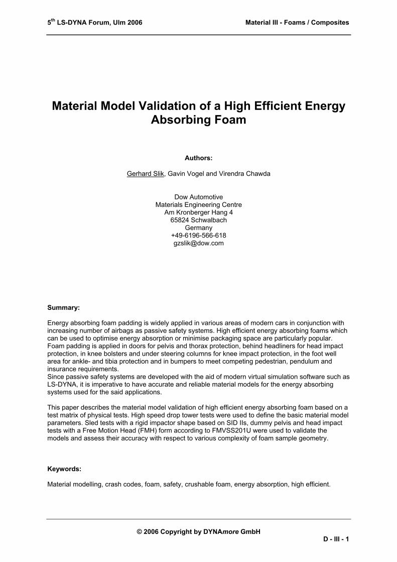
2 Foam Material The foam considered in the present paper is a closed cell styrenic foam, specially developed for energy absorption in automotive applications. It is produced via an extrusion process by The Dow Chemical Company and commercialized under the name IMPAXX™. The continuous extrusion production process ensures a constant quality and a high level of consistency of the material properties. Foam boards are formed in the extrusion process from which parts (pads) can be cut by hot wire or abrasive wire cutting technology. A typical quasi-static stress-strain characteristic of the foam is depicted in Figure 1.
Figure 1: Quasi-static stress-strain curve of IMPAXX™.
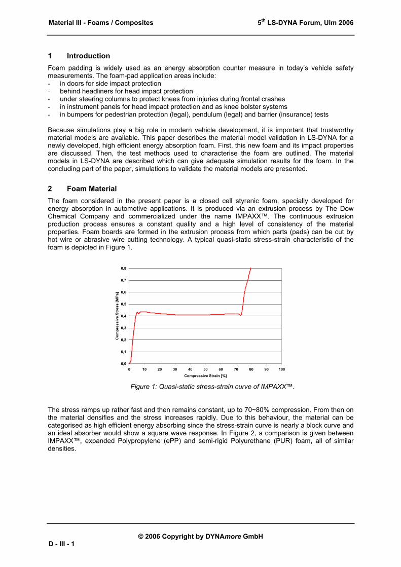
The stress ramps up rather fast and then remains constant, up to 70~80% compression. From then on the material densifies and the stress increases rapidly. Due to this behaviour, the material can be categorised as high efficient energy absorbing since the stress-strain curve is nearly a block curve and an ideal absorber would show a square wave response. In Figure 2, a comparison is given between IMPAXX™, expanded Polypropylene (ePP) and semi-rigid Polyurethane (PUR) foam, all of similar densities.
Figure 2: Compression curves of IMPAXX™ in comparison with ePP and PUR foam for equal density.
It is clear that ePP and PUR are not as efficient when compared to IMPAXX. Increasing the density of ePP or PUR would, apart from increasing the stress levels, also pre-pone the densification, thereby further decreasing their efficiencies. Besides maximising the energy absorption by choosing the right density/plateau stress level, it is as well possible to minimise packaging-space required to absorb a given amount of energy.
3 Testing To characterise the foam for its mechanical behaviour, four types of tests were conducted: - Quasi-static compression tests to study compression behaviour at low strain rates. - Drop tower tests to study the same at high velocity (high strain rates). - Impact tests with a pelvic shaped impactor on various sample shapes. - Free Motion Head form tests.
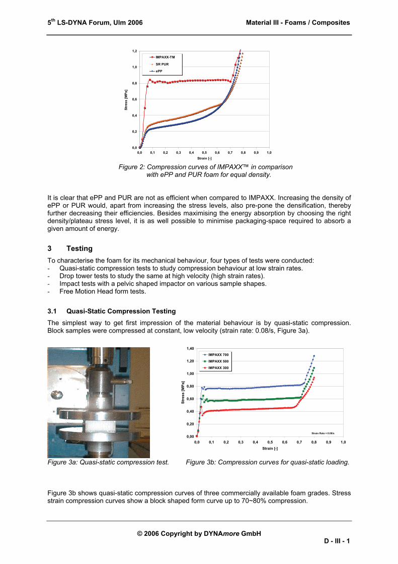
3.1 Quasi-Static Compression Testing
The simplest way to get first impression of the material behaviour is by quasi-static compression. Block samples were compressed at constant, low velocity (strain rate: 0.08/s, Figure 3a).
Figure 3a: Quasi-static compression test. Figure 3b: Compression curves for quasi-static loading. Figure 3b shows quasi-static compression curves of three commercially available foam grades. Stress strain compression curves show a block shaped form curve up to 70~80% compression.
Material behaviour at high velocity (high strain rates) were obtained from drop tower tests, see Figure 4a. Block samples were impacted. Impact mass, as well as the impactor drop height, were varied resulting in various impact velocities and impact energies. For these tests, flat impactors (discs) were used.
0,0
0,2
0,4
0,6
0,8
1,0
1,2
1,4
0 20 40 60 80 100Compressive Strain [%]
Com
pres
sive
Str
ess
[MPa
]
150 x 150 x 65mm 15mph
80 x 80 x 65mm 10mph
80 x 80 x 65mm Quasi-Static
Figure 4a: Drop tower test set-up. Figure 4b: Quasi-static versus dynamic compression curves. On comparing the drop tower tests with the quasi-static tests, it was found that the foam material was negligibly strain rate sensitive. Figure 4b shows compression curves of 65 mm thick samples impacted at 4.5 and 6.7 m/s (strain rates in the range of 70~100 1/s). Further, it was observed that there is low elastic recovery.
3.3 Dynamic Pelvic Impactor Testing
To investigate the material behaviour under impacts where the deformation is not uni-directional, a pelvis shaped impactor sled test was performed as shown in Figure 5. The impactor was of the shape of a pelvic of a SID IIs side impact dummy [1]. Its mass and impact velocity were 26.5 kg and 4.5 m/s, respectively. As the impactor in this case was not flat, deformation of the material was in multiple directions, which was a good basis for material model validation.
To investigate robustness of the material models in predicting the responses for other geometries, several shapes were considered. They were simple blocks, conical shaped samples and pyramid shaped samples. Figure 6 shows the various test sample shapes used for the pelvic impactor test.
Figure 6: Test sample shapes for the pelvic Impact tests: block, cone and pyramid.
3.4 Head Impact Testing
Head impact testing was performed based on FMVSS201U [2] guidelines, see Figure 7. A foam sample was attached to a steel profile which represented a typical cross-section of the body-in-white pillar of a car. By choosing the steel profile thickness, a required body-in-white stiffness was obtained.
Figure 7: Free Motion Head form test set-up.
4 Material Models In LS-DYNA [3], a variety of foam material models are available. Since IMPAXX™ material is not strain rate sensitive, it was not necessary to use a model which incorporates such behaviour. The material shows low elastic recovery, which in itself would lead to the choice of the crushable foam material model (Type 63). However, since good experience with the low density foam model (Type 57) [4, 5] existed, both models were investigated.
Material model type 57, MAT_LOW_DENSITY_FOAM [3], is meant for highly compressible, low density, elastic foams. After loading and subsequent unloading, the material completely recovers to its initial shape, which is in fact not the case for IMPAXX™ which shows low elastic recovery. This was overcome by giving the model a low hysteretic unloading value (e.g. 0.01) and a high number for the shape factor (e.g. 25). Since at these values elastic recovery is very slow, it can predict foams with no or low elastic recoverability as well. Figure 8 shows this effect for simulations with various hysteretic unloading factors and shape factors.
Figure 8: Effect of hysteretic unloading and shape factor for MAT57.
The load curve quickly drops down after it reached its highest point and unloads quickly for a low hysteretic unloading value and a high number for the shape factor. Further, a low damping factor was used in order to have low strain rate sensitivity for the material model. The stress versus volumetric strain was used as input for the model.
4.2 Material Model Type 63
Material model type 63, MAT_CRUSHABLE_FOAM [3], was selected for the material discussed in this paper because for this material model, no elastic recovery occurs where IMPAXX™ shows low elastic recovery. This is illustrated in Figure 9; a simulated load curve shows no elastic rebound of the impactor and the load curve drops immediate to 0 in the unloading phase.
Figure 9: Simulated load curve for material type 63.
A low value (e.g. 0.05) for the damping factor ensures a low strain rate sensitivity. The stress versus volumetric strain is used as input for the model.
5 Simulations and Validation In the last section, it was shown that both LS-DYNA material model 57 and 63 can represent IMPAXX™ in an appropriate way. In this section, the simulations of the tests to validate these models are described: - drop tower impact test of block samples with a flat impactor, - impact tests with a pelvic shaped impactor on block-, cone- and pyramid shaped samples, - head impact tests with a Free Motion Head form.
5.1 Drop Tower Simulation
Drop tower measurements with a flat impactor were taken on 60 mm thick samples. Test results were acceleration versus time, converted to load versus displacement and subsequently, converted to stress versus strain. The smoothened average stress-strain curve was taken as the input stress-strain curve for the material models. Figure 10a shows the finite element model of the drop tower test set-up. Figure 10b shows the simulated load on the impactor versus the measured load. Both material types 57 and 63 show good correlation.
Figure 10a: FE model of drop tower set-up. Figure 10b: Simulation vs. measurement of drop tower tests.
5.2 Pelvic Impactor Simulations
The pelvic impact test set-up was modelled as shown in Figure 11a. The pelvic impactor and the support wall were modelled as rigid bodies. The wall was supported by a spring to account for the compliance in the test rig. The foam sample was modelled with material model type 57 and 63. Results of the simulations are shown in Figures 11b, 11c and 11d for the individual geometries: block, cone, and pyramid samples. Both material types gave identical performance. The amount of intrusion/displacement of the impactor, maximum load and the curve shapes show good correlation of simulations versus tests.
Figure 11a: FE Model of the pelvic impactor test. Figure 11b: Simulation vs. test results of pelvic impact on block samples.
Figure 11c: Simulation vs. test results of pelvic Figure 11d: Simulation vs. test results of pelvic impact on cone samples. impact pyramid samples.
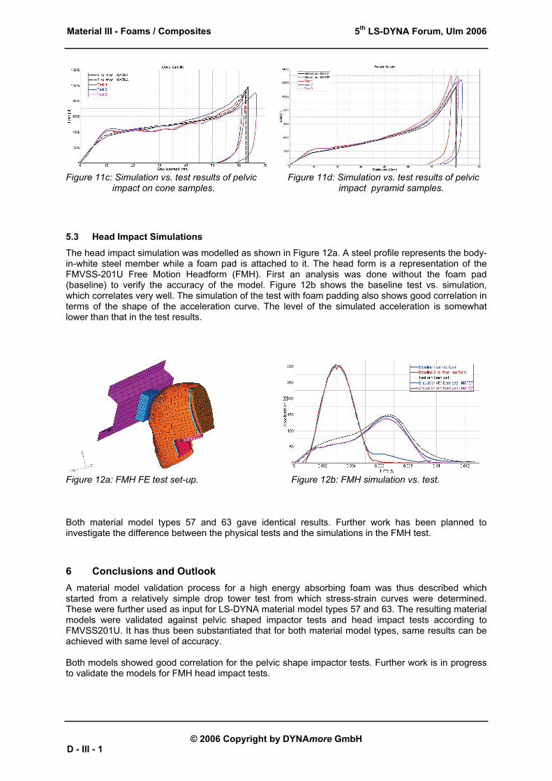
5.3 Head Impact Simulations
The head impact simulation was modelled as shown in Figure 12a. A steel profile represents the body-in-white steel member while a foam pad is attached to it. The head form is a representation of the FMVSS-201U Free Motion Headform (FMH). First an analysis was done without the foam pad (baseline) to verify the accuracy of the model. Figure 12b shows the baseline test vs. simulation, which correlates very well. The simulation of the test with foam padding also shows good correlation in terms of the shape of the acceleration curve. The level of the simulated acceleration is somewhat lower than that in the test results.
Figure 12a: FMH FE test set-up. Figure 12b: FMH simulation vs. test. Both material model types 57 and 63 gave identical results. Further work has been planned to investigate the difference between the physical tests and the simulations in the FMH test.
6 Conclusions and Outlook A material model validation process for a high energy absorbing foam was thus described which started from a relatively simple drop tower test from which stress-strain curves were determined. These were further used as input for LS-DYNA material model types 57 and 63. The resulting material models were validated against pelvic shaped impactor tests and head impact tests according to FMVSS201U. It has thus been substantiated that for both material model types, same results can be achieved with same level of accuracy. Both models showed good correlation for the pelvic shape impactor tests. Further work is in progress to validate the models for FMH head impact tests.
7 References [1] www.ftss.com. [2] Occupant Protection in Interior Impact; Code of Federal Regulations (CFR), Title 49, Chapter V, Part 571, Subtitle B, Section 571.201 (August 1995). [3] LSTC, LS-DYNA3D User’s Manual - Version 970. [4] Burr, S., Vogel. G., Material Model Development for Impact Analysis of Oriented Polypropylene Foam Structures, SAE Paper 2001-01-0310, 2001 Detroit. [5] Toccalino, E., FMVSS201U: Simulation Techniques for Energy Absorbing foams, Impact on
Results and on Turn-around Time, 19th CAD-FEM User’s Meeting 2001, Potsdam. “This information is considered accurate and reliable as of August 14, 2006 and is presented in good faith. No warranty, expressed or implied, is given nor is freedom from any patent owned by The Dow Chemical Company or others to be inferred. Since Dow has no control over how this information may ultimately be used, all liability is expressly disclaimed and Dow assumes no obligation or liability therefore.”