Page 1
TECHNICAL SPECIFICATION OF CONTROL & RELAY PANEL FOR 33,22 AND 11 KV LINES AND 33/11, 33/22
AND 22/11 KV TRANSFORMER PANEL WITH & WITHOUT DIFFERENTIAL PROTECTION
Tech Spec No. CE/T-QC/MSC/Control & Relay Panel Date: 16.06.2020 Page 1 of 76
MATERIAL SPECIFICATIONS CELL
TECHNICAL SPECIFICATION
FOR
CONTROL & RELAY PANEL FOR 33, 22 AND 11 KV LINES AND 33/11, 33/22 AND
22/11 KV TRANSFORMER PANEL WITH & WITHOUT DIFFERENTIAL
PROTECTION
Page 2
TECHNICAL SPECIFICATION OF CONTROL & RELAY PANEL FOR 33,22 AND 11 KV LINES AND 33/11, 33/22
AND 22/11 KV TRANSFORMER PANEL WITH & WITHOUT DIFFERENTIAL PROTECTION
Tech Spec No. CE/T-QC/MSC/Control & Relay Panel Date: 16.06.2020 Page 2 of 76
Clause No. Contents
1 Scope
2 Service Conditions
3 Constructional Details
4 Protective Relays And Control / Indication Equipment’s
5 Mimic Diagram
6 Circuit breaker Control Switch
7 Semaphore Indicators
8 Annunciators
9 Indicating LED
10 Trip circuit supervision scheme
11 Master Trip relays
12 Principal requirements of protective relays, auxiliary relays breaker control
switches etc.
13 Metering
14 General Requirements
15 Tests
16 Inspection
17 Performance Guarantee
18 Acceptance And Routine Tests
19 Documentation
20 Packing And Forwarding
21 Qualifying Requirement
22 Documents to be submitted along with offer.
Annexure
IA/IB/IC
Bill Of Material
Schedule II Schedule of Unit Rate
Schedule III Past Supply Details
Schedule IV Undertaking from Relay Manufacturer.
Schedule V Undertaking from Meter Manufacturer.
Annexure. - A-Technical specification for3 O/C + 1 E/F Protection Relay
Annexure B-Technical specification for Differential protection Relay
Annexure -C- Drawings for Control and Relay Panel
Annexure D. Guaranteed Technical Particulars format for Control and Relay Panels
Annexure -E-Technical specification for HT Static Trivector TOD Energy meter
I N D E X
Page 3
TECHNICAL SPECIFICATION OF CONTROL & RELAY PANEL FOR 33,22 AND 11 KV LINES AND 33/11, 33/22
AND 22/11 KV TRANSFORMER PANEL WITH & WITHOUT DIFFERENTIAL PROTECTION
Tech Spec No. CE/T-QC/MSC/Control & Relay Panel Date: 16.06.2020 Page 3 of 76
1. SCOPE:
1.1. This specification covers design, manufacture, assembly, testing before supply, inspection,
packing and delivery and other basic technical requirements in respect of control and relay
panels for 33,22 and 11 kV lines, 33/11,33.22 and 22/11 KV Power Transformers without
differential protection and 33/11,33.22 and 22/11 KV Power Transformers with differential
protection to be installed at various 33/11.33/22 and 22/11 kV sub-stations in Maharashtra. The
equipment to be supplied against this specification are required for vital installations where
continuity of service is very important. The design, materials and manufacture of the equipment
shall, therefore, be of the highest order to ensure continuous and trouble-free service over the
years.
1.2. The equipment offered shall be complete with all parts necessary for their effective and trouble-
free operation. Such parts will be deemed to be within the scope of the supply irrespective of
whether they are specifically indicated in the commercial order or not.
1.3. It is not the intent to specify herein complete details of design and construction. The equipment
offered shall conform to the relevant standards and be of high quality, sturdy, robust and of
good design and workmanship complete in all respects and capable to perform continuous and
satisfactory operations in the actual service conditions at site and shall have sufficiently long
life in service as per statutory requirements. If the dimensional drawings attached with this
specification and the notes thereto are generally of illustrative nature. In actual practice, not
withstanding any anomalies, discrepancies, omissions, in-completeness, etc. in these
specifications and attached drawings, the design and constructional aspects, including materials
and dimensions, will be subject to good engineering practice in conformity with the required
quality of the product, and to such tolerances, allowances and requirements for clearances etc.
as are necessary by virtue of various stipulations in that respect in the relevant Indian
Standards, IEC standards, I.E. Rules, I. E. Act and other statutory provisions.
1.4. The Tenderer/supplier shall bind himself to abide by these considerations to the entire
satisfaction of the purchaser and will be required to adjust such details at no extra cost to the
purchaser over and above the tendered rates and prices.
2. SERVICE CONDITIONS:
2.1. System particulars:
a. Nominal system voltage ... 33 kV ,22kV & 11 kV
b. Corresponding highest system voltage ... 36 kV ,24 kV & 12 kV
c. Frequency ... 50 Hz±3%
d. Number of phases ... 3
e. Neutral earthing ... Solidly grounded
2.2. Equipment supplied against the specification shall be suitable for satisfactory operation under the
following tropical conditions: -
a. Max. ambient air temperature : 50 ° C
b. Max. relative humidity : 100 %
c. Max. annual rainfall : 1450 mm
d. Max. wind pressure : 150 kg/sq.m.
e. Max. altitude above mean sea level : 1000 mtrs.
f. Isoceranic level : 50
Page 4
TECHNICAL SPECIFICATION OF CONTROL & RELAY PANEL FOR 33,22 AND 11 KV LINES AND 33/11, 33/22
AND 22/11 KV TRANSFORMER PANEL WITH & WITHOUT DIFFERENTIAL PROTECTION
Tech Spec No. CE/T-QC/MSC/Control & Relay Panel Date: 16.06.2020 Page 4 of 76
g. Seismic level(Horizontal acceleration) : 0.3 g.
h. Climatic Condition Moderately hot and humid tropical climate conducive to rust and fungus
growth.
i. Reference Ambient Temperature for temperature rise : 50 deg C
2.3. The climatic conditions are prone to wide variations in ambient conditions and hence the
equipment shall be of suitable design to work satisfactorily under these conditions.
2.4. Auxiliary supplies available at the various sub-stations are as follows:-
2.4.1. Rating:
i. A. C. Supply 240 volts with ± 10% variation
ii D.C. Supply 30 V DC with +10% to – 15% variation
iii Frequency 50 Hz with ±3%
2.5. The control & Relay Panels and various sub-units/components mounted on the panels shall
conform to the latest revisions of the following standards :
a) IS 12063/1987 Degree of Protection provided for enclosure of
electrical equipment.
b) IS 5/2004 Color for ready mixed paints & enamels.
c) IS 3231 / 1986 & 1987 Electrical relays for power system protection
d) IEC 60255 amended up to date Numerical biased protection relay
d) IS 8686/1977 Static Protective Relays
e) IS 1248/2003 Indicating instruments
f) IS 15959/2011 & IS
14697/1999(amended upto date)
HT Static Tri vector TOD Energy meter
g) IEC 337 & 337-1 ,IS 6875
amended up to date
Control switches( LV Switching devices for control
and auxiliary circuit)
h) IS 4794/1968 & 1986 Push buttons
i) IS:5578/1984 Marking of insulated conductors.
3. CONSTRUCTIONAL DETAILS :
3.1 The C&R panels against this specification shall be simplex type with all controls, indications, meters
and protective relays mounted on the front.
3.2 Each C&R panel for 33,22 and 11 kV lines shall accommodate all the necessary equipment required
for one feeder circuits.
3.3 Control and relay panels meant for 33/11 kV ,33/22 KV and 22/11 KV Power Transformer
shall accommodate all the necessary equipment for one transformer circuit.
3.4 The panels shall be free-standing, floor mounting type suitable for indoor installation. Panels
shall be completely metal enclosed, and shall provide degree of protection not less than IP 30 in
accordance with IS 12063/1987 Type test report in this respects shall be furnished with offer.
3.5 Panels shall be made of folded construction rigid structural frames enclosed completely with
smooth finished rolled sheet steel of thickness not less than 3 mm for front portion of panel and 2 mm for
other portions of panels. Sufficient re-enforcement shall be provided for level surfaces, so as to have
Page 5
TECHNICAL SPECIFICATION OF CONTROL & RELAY PANEL FOR 33,22 AND 11 KV LINES AND 33/11, 33/22
AND 22/11 KV TRANSFORMER PANEL WITH & WITHOUT DIFFERENTIAL PROTECTION
Tech Spec No. CE/T-QC/MSC/Control & Relay Panel Date: 16.06.2020 Page 5 of 76
resistance to vibration and rigidity during transport, installation and operation.
3.6 Each simplex panel shall have suitable hinged doors at the back. The doors shall be provided
with 3-point locks operated by suitable handle. Bottom plates of the panels shall be fitted with removable
gland plates to allow cable entries from the bottom. Gland plates shall be suitable for fixing the cable
glands at an elevated height of at least 100 mm above the ground level. Terminal Connectors and Test
terminal blocks for cables shall be fixed at an elevated height of at least 200 mm above the Bottom plate.
3.7 Design, materials selection and workmanship shall be such as to result a neat appearance
both inside and outside with no welds, rivets or bolt heads apparent from outside. Steel sheets shall be
suitably treated to achieve neat appearance and also long life. Final painting of panels shall be done with
Light Grey color to shade no.631 as per IS-5, for both interior and exterior. Epoxy powder coating
method shall be used for painting, and shall have Matty finish.
3.8 All wiring shall be carried out with 1100 volts grade single core, multistoried flexible tinned
copper wires with PVC insulation. The conductor size shall be 2.5 sq. mm. (minimum). Wiring troughs
shall be used for routing the cables. Wire numberings and color code for wiring shall be as per IS
IS:5578/1984. The wiring should be encased in suitable width PVC casing. The wiring diagram for various
schematics shall be made on thick and durable white paper in permanent black ink and same should be
encased in plastic cover thermally sealed. It should be kept visibly in a pocket of size 350 x 400 mm of
MS sheet of 1 mm thickness, on the interior surface of rear door marked.
3.9 Terminal blocks shall be of clip-on design made out of non-trackable insulating material of 1100
V grade. All terminals shall be stud type, with all current carrying and live parts made of tinned plated
brass. The studs shall be of min 4 mm diameter brass. The washers, nuts, etc. used for terminal connectors
shall also be of tinned plated brass.
3.10 The terminal connector/blocks shall be disconnecting type terminal connectors with automatic
shorting of C.T. secondary terminals shall be provided in CT secondary circuit. All other terminal
connectors shall be Non- disconnecting type. Terminal should be shock protected in single molded piece.
Terminal block should have screw locking design to prevent loosening of conductor.
3.11 At least 20% spare terminals shall be provided. All terminals shall be provided with ferrules
indelibly marked or numbered and identification shall correspond to the designations on the relevant
wiring diagrams. The terminals shall be rated for adequate capacity which shall not be less than 10 Amps
for control circuit. For power circuit it shall not be less than 15 Amps.
3.12 MCBs of appropriate rating shall be provided for DC positive and negative of each circuit/sub-
circuit. MCBs shall also be provided for AC (240V) circuits. However HRC fuses of suitable rating shall
be provided for PT circuits.
3.13 All front mounted as well as internally mounted items including MCBs shall be provided with
individual identification labels. Labels shall be mounted directly below the respective equipment and shall
clearly indicate the equipment designation. Labeling shall be on aluminum anodized plates of 1 mm
thickness, letters are to be properly engraved.
3.14 Each panel shall be provided with cubicle illumination lamp in shrouded holder, controlled by
door operated switch. Space heater of 80 W rating along with control switch shall be provided inside each
panel. Cubicle lamp and space heater shall be suitable to work on 240 V AC supply. In each panel, one 3-
pin 10 Amp industrial type power plug along with control switch shall be provided for extending 240 V
AC supply.
3.15 Each panel shall be provided with one earth bus of size 25 x 3 mm (minimum). The earth bus shall be of
tinned plated copper, and all metallic cases of relays, instruments etc. shall be connected to this earth bus
independently for their effective earthing. The wire used for earth connections shall have green insulation.
3.16 A) The single standalone panels shall be of overall dimensions 700(W) x 750(D) x 2310(H) mm. The
height 2310 mm is inclusive of the height of base frame. The height of base frame is generally 100
mm, and shall be painted black. Annexure C (Drg. No.T&QC/CRP/01, T&QC/CRP/02 and
Page 6
TECHNICAL SPECIFICATION OF CONTROL & RELAY PANEL FOR 33,22 AND 11 KV LINES AND 33/11, 33/22
AND 22/11 KV TRANSFORMER PANEL WITH & WITHOUT DIFFERENTIAL PROTECTION
Tech Spec No. CE/T-QC/MSC/Control & Relay Panel Date: 16.06.2020 Page 6 of 76
T&QC/CRP/03)
b) At places where there is a space constraint and extra space provision is required to be made for future
expansion, duplex or even triplex CR panels may also be used.
(Ref.O.N. No. CE/Infra/s/s layouts/Vendor approval/3141 dt.12.07.2017)
i) 11 KV- A (Incomer + feeder1) +B (feeder2+Feeder3),with overall dimension for A or B should be
700(W) x 600(D) x 2310(H) mm. (T&QC/CRP/04) Annexure C
ii) 11 KV- Incomer + 3 feeder1), with overall dimension should be
1200(W) x 600(D) x 2310(H) mm. (T&QC/CRP/05) Annexure C
3.17 The constructional details and mounting arrangement for various flush mounted equipments shall be as per
the enclosed drawings. The center lines of any relays, if additionally provided, shall not be less than 450
mm from ground level.
3.18 In addition to the main circuit label, each panel shall be provided with a label indicating the following
details :
Name of supplier:
Purchase order ref: (T- dtd. )
DC voltage:
Panel sr.no :
3.19 This label shall be provided on the rear side close to the door handle. A sticker type Label indicating the
above details shall be provided on the packing case for easy identification.
4. PROTECTIVE RELAYS AND CONTROL / INDICATION EQUIPMENTS :
4.1 The relays, switches, meters and other accessories offered shall be subject to maximum of three
reputed make and of proven design. The bidders may offer more than one alternative, for each
equipment, provided all the alternatives meet the requirement of the technical specification. In case
any or all the alternatives offered is/are found to be not acceptable to MSEDCL, the bidder shall be
ready to offer any alternative equivalent which is acceptable to MSEDCL.
4.2 Protective relays:
4.2.1 For 33 KV lines, nondirectional 3 O/C & 1 E/F relay with High set Relay should be
provided. Numerical biased protection relays (Principle requirements are given in annexure-
II B) shall be suitable for auxiliary supply (30 V D.C.) and shall have a reset push button
and a test push button to test the relay function with provision to trip bypass push button.
All relays have 3 second IDMT characteristic. The O/C elements having current setting
variable from 5 % to 200 % in steps of 1 %., and E/F elements having current setting
variable from 5 % to 200 % in steps of 1 %. The communication Protocol for relays with
IEC 103)
4.2.2 For each incomer and feeder, high speed tripping relay shall be provided. Over current &
Earth fault relay shall be connected to trip coil through high speed trip relay.
4.2.3 LCD Display: Relay should have minimum 2 Line LCD backlit display.
4.2.4 For 33/11 kV,33/22 KV and 22/11 KV transformers of rating 10 MVA, differential
protection shall be provided. Transformer differential relay shall be numeric type
differential relay, with in built current amplitude & vector group compensation feature &
also with differential high set element for two winding power transformer conforming IEC
60255. (principle requirements are given in annexure- II B. The communication Protocol for
relays with IEC 103)
4.2.5 All the relays meant for panels shall be suitable for 30 V DC.
4.2.6 In case any special software/devices are required for the testing/setting of the protective
relays, the bidder shall include one set of such accessories in the offer free of cost. The unit
price for such items shall be indicated in the offer so as to enable the purchaser to order out
Page 7
TECHNICAL SPECIFICATION OF CONTROL & RELAY PANEL FOR 33,22 AND 11 KV LINES AND 33/11, 33/22
AND 22/11 KV TRANSFORMER PANEL WITH & WITHOUT DIFFERENTIAL PROTECTION
Tech Spec No. CE/T-QC/MSC/Control & Relay Panel Date: 16.06.2020 Page 7 of 76
more sets if required.
4.2.7 All relays should be suitable for flush mounting on C & R panel and all connections should
be on backside. The relay should be draw –out type preferably with automatic shorting of CT
circuit at a time of removal of relay from the casing.
4.2.8 In case the protective relays offered are not manufactured by the tenderer, an undertaking
from the respective relay manufacturer indicating his readiness to extend necessary technical
support and back-up guarantee as brought out in Schedule-V for the satisfactory operation of the relay shall be furnished by the tenderer in his offer. The tenderer shall also furnish an
undertaking (from the relay manufacturers) confirming that the relay offered is in the current
range of manufacture and will not be phased out for at least 10 years from the date of supply.
4.2.9 Test terminal blocks used in metering circuit shall be suitable for 3 phase 4 wire type
connections.
5. MIMIC DIAGRAM:
5.1 Mimic diagrams depicting the bus and the relative position of circuit breakers and isolators shall be
provided on each control panel. Mimic diagram shall be neatly painted with the below listed color to
shades mentioned below. The mimic shall have 10 mm width. Non-Discrepancy control switch for
the C.B. shall be mounted within the mimic, indicating the C.B. ON/OFF status.
Sr. No. Voltage grade Color Shade no.
1 33 kV Brilliant green 221 as per IS 5
2 22 kV Brilliant green 221 as per IS 5
3 11 kV Traffic yellow 368 as per IS 5
6) Circuit breaker Control Switch:
6.1 Non- discrepancy type T-N-C type switch shall be provided for remote operation of circuit breaker.
. The switch shall be mounted in the mimic diagram itself such that the stay-put ('N') position will
render the continuity of the mimic. One green LED for 'breaker open' indication and one red LED
for 'breaker closed' indication shall also be provided adjacent to the T-N-C switch.
6.2 Switches should have finger touch proof terminals. For the convenience of maintenance, screw
driver guide should be from top/bottom of the switch and not from the side. Terminal wire should be
inserted from the side of the switch terminal.
6.3 Terminal screws must be captive to avoid misplace during maintenance.
6.4 Switch shall be with 48 mm x 48 mm escutcheon plate marked with Trip & Close.
6.5 Trip-neutral-close, with pistol grip handle must be pushed in to spring return to either trip or close
position from Neutral position for safety and not just turn to trip.
6.6 One contact to close in each position of Trip and Close. Contact not required in Neutral position.
Contact rating shall be 12 A at 30 V DC.
7.Semaphore Indicators:
7.1 When semaphore indicators are used for equipment positions, they shall be mounted in the mimic,
such that the equipment closed position shall complete the continuity of the mimic. Similarly,
when control switch of discrepancy type is used for equipment control, it shall be mounted in the
mimic such that the equipment closed position (i.e. control switch knob) shall complete the
continuity of the mimic.
7.2 Semaphore indicators shall be provided for isolators. The semaphore indicators shall be three
position type, having one intermediate position to indicate the "DC supply fail" condition.
Page 8
TECHNICAL SPECIFICATION OF CONTROL & RELAY PANEL FOR 33,22 AND 11 KV LINES AND 33/11, 33/22
AND 22/11 KV TRANSFORMER PANEL WITH & WITHOUT DIFFERENTIAL PROTECTION
Tech Spec No. CE/T-QC/MSC/Control & Relay Panel Date: 16.06.2020 Page 8 of 76
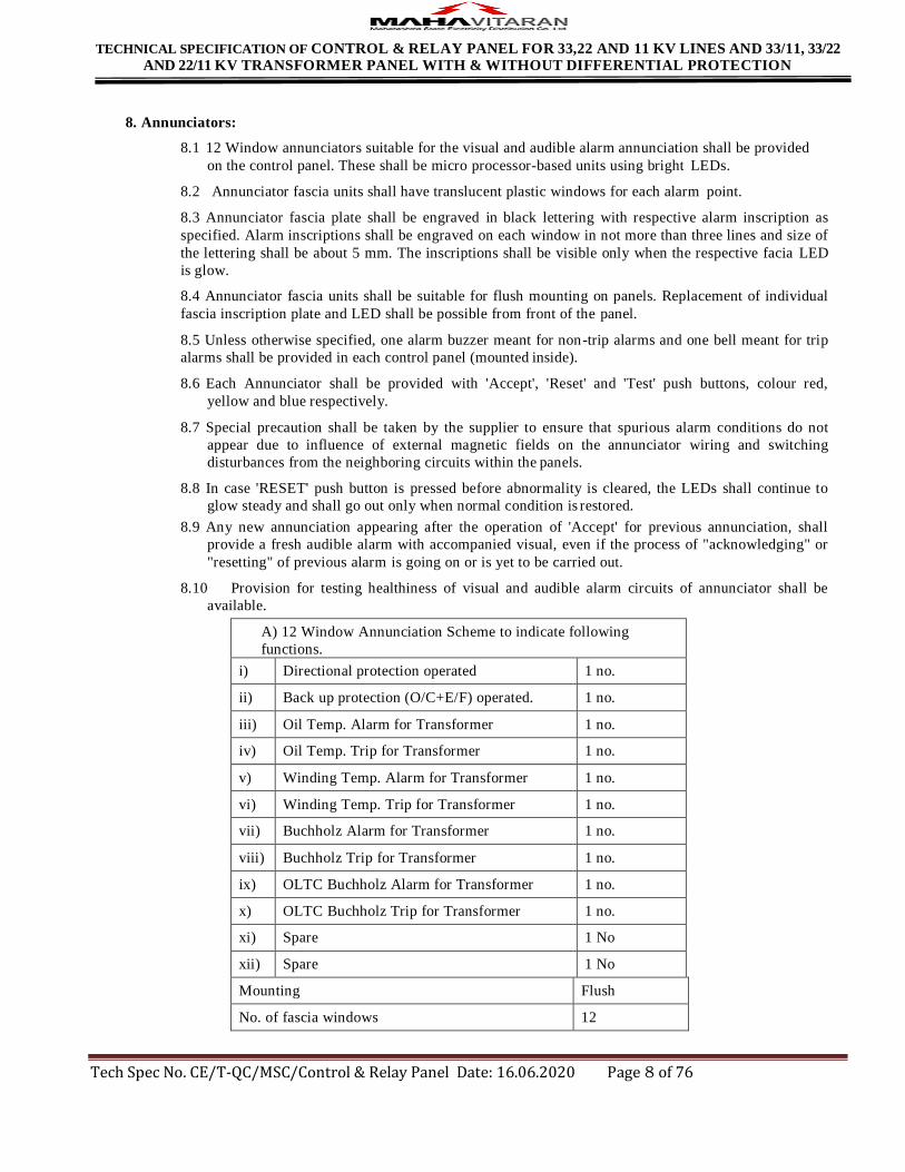
8. Annunciators:
8.1 12 Window annunciators suitable for the visual and audible alarm annunciation shall be provided
on the control panel. These shall be micro processor-based units using bright LEDs.
8.2 Annunciator fascia units shall have translucent plastic windows for each alarm point.
8.3 Annunciator fascia plate shall be engraved in black lettering with respective alarm inscription as
specified. Alarm inscriptions shall be engraved on each window in not more than three lines and size of
the lettering shall be about 5 mm. The inscriptions shall be visible only when the respective facia LED
is glow.
8.4 Annunciator fascia units shall be suitable for flush mounting on panels. Replacement of individual
fascia inscription plate and LED shall be possible from front of the panel.
8.5 Unless otherwise specified, one alarm buzzer meant for non-trip alarms and one bell meant for trip
alarms shall be provided in each control panel (mounted inside).
8.6 Each Annunciator shall be provided with 'Accept', 'Reset' and 'Test' push buttons, colour red,
yellow and blue respectively.
8.7 Special precaution shall be taken by the supplier to ensure that spurious alarm conditions do not
appear due to influence of external magnetic fields on the annunciator wiring and switching
disturbances from the neighboring circuits within the panels.
8.8 In case 'RESET' push button is pressed before abnormality is cleared, the LEDs shall continue to
glow steady and shall go out only when normal condition is restored.
8.9 Any new annunciation appearing after the operation of 'Accept' for previous annunciation, shall
provide a fresh audible alarm with accompanied visual, even if the process of "acknowledging" or
"resetting" of previous alarm is going on or is yet to be carried out.
8.10 Provision for testing healthiness of visual and audible alarm circuits of annunciator shall be
available.
A) 12 Window Annunciation Scheme to indicate following
functions.
i) Directional protection operated 1 no.
ii) Back up protection (O/C+E/F) operated. 1 no.
iii) Oil Temp. Alarm for Transformer 1 no.
iv) Oil Temp. Trip for Transformer 1 no.
v) Winding Temp. Alarm for Transformer 1 no.
vi) Winding Temp. Trip for Transformer 1 no.
vii) Buchholz Alarm for Transformer 1 no.
viii) Buchholz Trip for Transformer 1 no.
ix) OLTC Buchholz Alarm for Transformer 1 no.
x) OLTC Buchholz Trip for Transformer 1 no.
xi) Spare 1 No
xii) Spare 1 No
Mounting Flush
No. of fascia windows 12
Page 9
TECHNICAL SPECIFICATION OF CONTROL & RELAY PANEL FOR 33,22 AND 11 KV LINES AND 33/11, 33/22
AND 22/11 KV TRANSFORMER PANEL WITH & WITHOUT DIFFERENTIAL PROTECTION
Tech Spec No. CE/T-QC/MSC/Control & Relay Panel Date: 16.06.2020 Page 9 of 76
No. of windows per row 6
Supply voltage 30 V DC
No. of LEDs per window 2
Lettering on fascia plate Properly
engraved
9. Indicating LEDs :
9.1 Indicating LEDs shall be panel mounting type with rear terminal connections. LED shall be
provided with series connected resistors preferably built-in in the LED assembly. LEDs shall have
translucent LED covers to diffuse lights, color red, green, amber, clear white or blue as specified.
The LED cover shall be preferably of screw-on type, unbreakable and molded from heat resisting
material.
9.2 All indicator shall have bright LEDs having long life. Conventional bulbs are not acceptable.
9.3 The indicating LEDs with resistors shall withstand 120% of rated voltage on a continuous basis.
10. Trip circuit supervision (Relay) :
10.1 Trip circuit supervision (Relay) should be provided for each trip coil individually shall be such that
testing of trip circuit healthiness is possible irrespective of whether the C. B. is in the closed or
open position. The Trip Circuit Healthy LED should glow continuously in CB ‘ON’ Position
and on demand in C.B. ‘OFF” position. The rating of dropping resistance in series with Trip
Circuit Healthy LED shall be such that the Trip Coil should not get damaged because of
continuous current flowing through it.
11. Master Trip relays:
11.1 The trip relays shall be high set, hand reset type. The relay shall have heavy duty contacts suitable
for tripping function. Relay shall have minimum 2NO + 2NC contacts.
12. Principal requirements of protective relays, metering equipments, auxiliary relays breaker control
switches etc. are as follows:
12.1 Ammeter:
12.1.1 Each circuit one ammeter and associated selector switch shall be provided.
Mounting Flush
Size 48 x 96 sq. mm. case
Response Time 1 second
Operating Temperature Up to 55°C
Dielectric Strength 2 kV RMS for 1 minute
Frequency 50 Hz
Operating Current 1 A from CT Secondary.
Type Panel Mounting with 31/2 Digital Display
12.2 Ammeter selector switch:
12.2.1 Ammeter Selector switch shall be a four-position (3 way with off) rotary type with R, Y, B and
'OFF' positions marked clearly on 48x48 mm brushed aluminum plate with black handle.
Switch should be single hole mounting and not screw mounting. Switches should have finger
touch proof terminals. Terminal wire should be inserted from the side of the switch terminal.
Page 10
TECHNICAL SPECIFICATION OF CONTROL & RELAY PANEL FOR 33,22 AND 11 KV LINES AND 33/11, 33/22
AND 22/11 KV TRANSFORMER PANEL WITH & WITHOUT DIFFERENTIAL PROTECTION
Tech Spec No. CE/T-QC/MSC/Control & Relay Panel Date: 16.06.2020 Page 10 of 76
Terminal screw must be captive to avoid misplace during maintenance.
Rated Insulation Voltage 1100 V
Rated Impulse withstand voltage 6 kV
Rated Operational Current 12 A
12.3 Volt Meter.
Mounting Flush
Size 48 x 96 sq. mm. Case
Response Time 1 second
Operating Temperature Up to 55°C
Dielectric Strength 2 kV RMS for 1 minute
Auxiliary Supply 110 V
Frequency 50 Hz
Operating Voltage 110 V from PT Secondary.
Type Panel Mounting with 31/2 Digital Display
12.4 Volt Meter selector switch:
12.4.1 Voltmeter Selector Switch shall be seven position type (6 way & off ) with 3 phase to phase
and 3 phase to neutral position marked clearly on 48x48 brushed aluminum plate with black
handle. Switch should be single hole mounting and not screw mounting. Switches should
have finger touch proof terminals. Terminal wire should be inserted from the side of the
switch terminal. Terminal screw must be captive to avoid misplace during maintenance.
Rated Insulation Voltage 1100 V
Rated Impulse withstand voltage 6 kV
Rated Operational Current 12 A
12.5 Frequency Meter.
Mounting Flush in 96 sq.mm. case
Size 96 mm x 96 mm x 70 mm
Range 45 Hz to 55 Hz
Dielectric Strength 2 kV RMS for 1 minute
Power Consumption Less than 6 VA
Type Electronic 4 Digit Digital frequency meter.
Display Seven segments red color LED Display with 0.5” height
IS Reference IS:1248
Page 11
TECHNICAL SPECIFICATION OF CONTROL & RELAY PANEL FOR 33,22 AND 11 KV LINES AND 33/11, 33/22
AND 22/11 KV TRANSFORMER PANEL WITH & WITHOUT DIFFERENTIAL PROTECTION
Tech Spec No. CE/T-QC/MSC/Control & Relay Panel Date: 16.06.2020 Page 11 of 76
12.6 Heater
Capacity 80 Watts
Voltage 240 V AC
Type Strip type
12.7 Semaphore indicator
Type 3 Position type or Equivalent
Mounting Flush
Coil rating 30 V DC
Burden Less than 2 VA
Terminals 3 nos, central terminal is common for negative, positive is
connected to 1 or/and 2.
12.8 Self resetting buzzer
Self resetting buzzer should sound for fixed time of 60 seconds interval and stop automatically
12.9 Three elements Auxiliary Relay hand reset type conforming IS 3231 for Transformer
Auxiliary voltage 30 V D.C.
Coil rating 30V D.C., voltage band for satisfactory operation: 50 to 120% of
rated voltage
Operating Time 25 m. seconds nominal at rated voltage
Burden of relay coil
watts (Max)
40 Watt at rated voltage for each coil
Operating temp -10 deg C to 55 deg C.
Operational indication
for each element
Mechanical red color Flag : Hand Reset Type
12.10 High speed tripping relay hand reset type confirming to IS – 3231
Auxiliary voltage 30 V D.C.
Coil rating 30V D.C., voltage band for satisfactory operation: 50 to 120% of
rated voltage
Operating Time 10 milliseconds nominal at rated voltage
Burden of relay coil
watts (Max)
Low burden 40 Watt at rated voltage
Operating temp -10 deg C to 55 deg C.
Operational indication
for each element
Mechanical red color Flag : Hand Reset Type
Contact Configuration 3 NO + 2 NC combination with additional hand reset coil cut of
contact (Seal in contact)
Page 12
TECHNICAL SPECIFICATION OF CONTROL & RELAY PANEL FOR 33,22 AND 11 KV LINES AND 33/11, 33/22
AND 22/11 KV TRANSFORMER PANEL WITH & WITHOUT DIFFERENTIAL PROTECTION
Tech Spec No. CE/T-QC/MSC/Control & Relay Panel Date: 16.06.2020 Page 12 of 76
Contact ratings:
Make and carry A.C. 1250 VA with max 5 amp & 660 Volts
D.C. 1250 W dc with max 5 amp & 660 Volts
Make and carry for 3
sec.
A.C. 7500 VA with max 30 amp & 660 Volts
D.C. 7500 W dc with max 30 amp & 660 Volts
Break A.C. 1250 VA with max 5 amp & 660 Volts
D.C. – 100 W resistive 50 watt inductive with max 5 amp & 660
Volts
Insulation 2 KV RMS, 50Hz for 1 min.
2.5 KV/1 sec between all terminals & case as per IS 3231.
1 KV RMS, 50Hz for 1 min. across open contact
Type of mounting Flush
13. Numerical non directional 3 O/C + 1 E/F with high set feature for lines . (As per Annexure -A)
14. Numerical biased differential protection relay (As per Annexure -B)
15. HT Static Trivector TOD Energy Meter:( As per Annexure -E)
16.GENERAL REQUIREMENTS :
16.1 The panels shall be delivered to the various consignees of the MSEDCL as will be informed to
the successful tenderers. The panels shall be transported only by road and shall be suitably packed to
avoid damages during transit.
16.2 Equipment covered in this specification shall be guaranteed for a period of 66 months from the
date of dispatch or 60 months from the date of commissioning, whichever is earlier. However, any
engineering error, omission, wrong provision, etc. which do not have any direct effect on the time
period shall be attended to as and when observed/ pointed out, without any extra price.
16.3 Three sets of drawings shall be submitted for approval within 30 days from the date of issue of
the Letter Of Award. The suppliers shall furnish 3 sets of the final drawings with copies of technical
literature and commissioning manuals along with panel. All drawings shall be A3 size.
17. TESTS :
17.1 Type Test :
17.1.2 Control & Relay Panels offered in the Tender should have been successfully type tested at
NABL in line with relevant Standards and the Technical Specification within the last 7
(Seven) years prior to the date of opening of the Tender.
17.1.2 Protective relays, Trivector Energy Meters , Annunciator, etc. should have been
successfully type tested at Independent Government Laboratories in line with relevant
Standards and the Technical Specification within the last 7(Seven ) years prior to the date
of opening of the Tender.
17.1.3 Copies of type test reports in respect of all offered equipment/material shall invariably be
Page 13
TECHNICAL SPECIFICATION OF CONTROL & RELAY PANEL FOR 33,22 AND 11 KV LINES AND 33/11, 33/22
AND 22/11 KV TRANSFORMER PANEL WITH & WITHOUT DIFFERENTIAL PROTECTION
Tech Spec No. CE/T-QC/MSC/Control & Relay Panel Date: 16.06.2020 Page 13 of 76
submitted along with the offer. Incomplete type test reports will be treated as invalid and
the offer will be liable for rejection.
17.1.4 If offered equipment/material are type tested before 7 years from the opening of tender, the
same was considered for placement of order. However, bidder has to carry out these test at
his own cost before commencement of first supply. Undertaking in this respect has to be
submitted along with offer otherwise the offer will be liable for rejection.
17.1.5 The bidder shall submit copies of the valid Type Test Reports for approval immediately on
receipt of LOA.
17.1.6 Even if the equipment/material has been type tested within five years, the purchaser
reserves the right to demand repetition of one or more tests included in the list of type tests
in the presence of purchaser's representative.
17.1.7 The MSEDCL shall have the option to carry out various tests including type tests as per
specification on the samples selected at random from the supplies effected, to ensure that
the supplies conform in quality and workmanship to the relevant specification. The testing
shall be done at independent laboratory at MSEDCL’s cost. Due notice shall be given to
supplier for such sample selection and such testing thereof to enable him to be present for
the same if so desired by him. If the supplier or his authorized representative fails to attend
the sample selection and testing, the same shall be carried out unilaterally by the MSEDCL
and the result thereof shall be binding upon the supplier. In case the sample selected from
the supplies fails to withstand the required tests, then
17.1.8 for first time failure of sample,
17.1.8.1 Supplier shall have to replace the full quantity of the respective inspected lot
supplied to various Stores and lying unused at Stores.
17.1.8.2 For the quantity already accepted against the order and used, deduction in price . of
10% of the value of material supplied shall be made
AND
17.1.9 in respect of further supplies made against the order, if failure of samples is noticed (i.e.
second time failure against the order)
17.1.9.1 The quantity lying unused at various Stores shall be rejected.
17.1.9.2 for the quantity already accepted against the order and used, deduction in price of
10% of the value of material supplied shall be made.
17.1.9.3 Balance quantity against the order including the rejected qty. shall be cancelled
without any liability on either side,
17.1.9.4 The firm will be debarred from dealing with the MSEDCL upto a period of three
years from the date of rejection.
17.1.10 The purchaser reserves the right to conduct tests included in the list of Type Tests on
requisite number of samples/items from any of the lots during the tenure of the supply, at
the purchaser's cost in the presence of manufacturer's representatives. If th e
equipment/material does not withstand the type test, then the equipment/material supplied
till then will be liable for rejection. The supplier, in such an eventuality, shall be allowed to
modify the equipment and type test the same again at his cost in the presence of the
purchaser's representative. These type tests shall however be conducted by the supplier
within 15 days. After successful passing of the type tests, all the equipments/materials
supplied earlier shall be modified in line with the equipment/materials which have
successfully passed the type test. In case the supplier fails to carry out the Type Test within
reasonable time or does not agree to carry out the type tests at his cost, his
Page 14
TECHNICAL SPECIFICATION OF CONTROL & RELAY PANEL FOR 33,22 AND 11 KV LINES AND 33/11, 33/22
AND 22/11 KV TRANSFORMER PANEL WITH & WITHOUT DIFFERENTIAL PROTECTION
Tech Spec No. CE/T-QC/MSC/Control & Relay Panel Date: 16.06.2020 Page 14 of 76
equipment/material supplied earlier shall be rejected and the order placed shall be cancelled
and payments made earlier for these supplies shall be recovered by the purchaser.
18 INSPECTION:
18.1 The inspection may be carried out by the purchaser at any stage of manufacture. The successful
Tenderer shall grant free access to the purchaser's representative/s at a reasonable notice when the work
is in progress. Inspection and acceptance of any equipment under this specification by the purchaser,
shall not relieve the supplier of his obligation of furnishing equipment in accordance with the
specification and shall not prevent subsequent rejection if the equipment is found to be defective.
18.2 The supplier shall keep the purchaser informed in advance, about the manufacturing program so
that arrangement can be made from stage inspection.
18.3 The purchaser reserves the right to insist for witnessing the acceptance/routine testing of the
bought out items. The supplier shall keep the purchaser informed, in advance, about such testing
program.
19. PERFORMANCE GUARANTEE:
19.1. Equipment covered in this specification shall be guaranteed for a period of 66 months from the
date of dispatch or 60 months from the date of commissioning, whichever is earlier. However, any
engineering error, omission, wrong provision, etc. which do not have any effect on the time period
shall be attended to as and when observed/pointed out without any price implications.
19 Acceptance and Routine Tests :
19.1 All acceptance and routine tests as stipulated in the relevant standards shall be carried out by
the supplier in the presence of the Purchaser's representative without any extra cost.
19.2 Immediately after finalization of the program of type/acceptance/routine testing, the supplier
shall give four weeks advance intimation to the purchaser, to enable him to depute his representative
for witnessing the tests.
19.3 The supplier shall carryout all the relevant physical verifications and functional tests as
applicable at his works on all the finished C&R panels. Copies of these test certificates duly endorsed
by the supplier's testing engineer shall be furnished to the inspecting officer of the MSEDCL. The
inspecting officer reserves the right to insist for repetition of functional tests on any or all of the
panels offered for inspection, and the supplier shall arrange for the same:
20 DOCUMENTATION
20.1 After issue of letter of Award, the successful tenderers shall submit 3 sets of complete drawings
alongwith detailed bill of materials for approval to the Chief Engineer, (MMD), Ist floor, Prakashgad,
MSEDCL, Bandra (E). If any modifications are required on these, the same will be conveyed to the
supplier who shall modify the drawings accordingly and furnish final drawings for approval. In normal
practice, the documents submitted for approval will be commented upon or approved if in order, within
30 days from the date of receipt of the same in the Distribution Department. The period of
commencement of delivery shall include submission and approval of drawings/BOM.
20.2 The manufacturing of the equipment’s shall be strictly in accordance with the approved
drawings and no deviation will be permitted without the written approval of the Distribution
Department. All manufacturing and fabrication work in connection with the equipments prior to the
approval of the drawings shall be at the supplier's risk.
20.3 After approval of the drawings and bills of materials, the suppliers shall submit detailed packing
lists for approval. After approval, copies of these packing lists shall be forwarded to the respective
consignees. Copies of packing lists shall also be submitted to the Chief Accounts Officer (SB),
MSEDCL, along with the bills for payment.
Page 15
TECHNICAL SPECIFICATION OF CONTROL & RELAY PANEL FOR 33,22 AND 11 KV LINES AND 33/11, 33/22
AND 22/11 KV TRANSFORMER PANEL WITH & WITHOUT DIFFERENTIAL PROTECTION
Tech Spec No. CE/T-QC/MSC/Control & Relay Panel Date: 16.06.2020 Page 15 of 76
20.4 In case the supplier fails to furnish the required drawings and manuals even at the time of supply
of equipment, the date of furnishing of drawings/manuals will be considered as the date of supply of
equipment for the purpose of computing penalties for late delivery.
20.5 List of drawings to be submitted along with the offer is as under:
20.5.1 GA drawing for C & R panel.
20.5.2 Schematic drawing.
20.5.3 Typical single line diagram.
20.5.4 Bill of material for complete C & R panel.
20.5.5 Terminal block details .
20.6 The drawings, technical literature and manuals submitted by the tenderer along with his offer
shall be treated as purely and generally informative in nature and unless the details incorporated in
them are clearly and specifically brought out in the various Schedules for Guaranteed Technical
Particulars and Schedules of Deviations, the same shall not be binding upon the purchaser (a) for
evaluation of the offer and (b) for the order, if placed.
21 PACKING AND FORWARDING
21.1 Duly wired-up C & R panel with all relays and equipments mounted, shall be packed in crates
suitable for vertical/horizontal transport as the case may be and the packing shall be suitable to
withstand handling during the transport and outdoor storage during transit. The supplier shall be
responsible for any damage to the equipment during transit due to improper and inadequate
packing. The easily damageable materials shall be carefully packed and marked with the
appropriate caution symbols. Wherever necessary, proper arrangement for lifting, such as
lifting hooks etc. shall be provided. Any material found short inside the packing cases shall be
supplied by the supplier within 7 days without any extra cost.
21.2 Each consignment shall be accompanied by a detailed packing list containing the following
information:
21.2.1 Name of the consignee
21.2.2 Details of consignment.
21.2.3 Destination
21.2.4 Total weight of consignment
21.2.5 Sign showing upper/lower side of the crate.
21.2.6 Handling and unpacking instructions.
21.2.7 Bill of material indicating contents of each package.
21.3 All the equipment covered in this specification shall be delivered to the various stores centers of the
MSEDCL as will be intimated to the successful tenderers. The equipment shall be delivered to these
stores centers only by road transport, and shall be suitably packed to avoid damages during transit in the
case of indigenous supplies.
21.4 The tenderers shall quote delivery periods for various equipment, and shall stick up to the committed
delivery. It may clearly be noted that the delivery periods will under no circumstances be linked up with
other formalities like drawing approval, etc. It is therefore, the responsibility of the successful tenderers
to submit the drawings, bill of materials, packing lists, etc. in time and get these approved by the
Distribution Department of the MSEDCL.
21.5 Undertakings from relay manufacturer regarding:
21.5.1 Non-phasing out of the relays for at least 10 years from the date of supply (Schedule-IV (a))
Page 16
TECHNICAL SPECIFICATION OF CONTROL & RELAY PANEL FOR 33,22 AND 11 KV LINES AND 33/11, 33/22
AND 22/11 KV TRANSFORMER PANEL WITH & WITHOUT DIFFERENTIAL PROTECTION
Tech Spec No. CE/T-QC/MSC/Control & Relay Panel Date: 16.06.2020 Page 16 of 76
21.5.2 For extending technical support and back-up guarantee (when the relay is not manufactured by
the tenderer) (Schedule-IV (b))
21.6 Detailed catalogue/technical literature in respect of all components/accessories including bought- out
items.
Page 17
TECHNICAL SPECIFICATION OF CONTROL & RELAY PANEL FOR 33,22 AND 11 KV LINES AND 33/11, 33/22
AND 22/11 KV TRANSFORMER PANEL WITH & WITHOUT DIFFERENTIAL PROTECTION
Tech Spec No. CE/T-QC/MSC/Control & Relay Panel Date: 16.06.2020 Page 17 of 76
SCHEDULE-I A
(To be submitted, duly filled in, along with the offer)
Bill of materials for 33 KV feeder C&R panels
Sr. No Description Quantity Make and Type design
1 Circuit label 1 No.
2 Mimic section(Brilliant green paint to shade No.221 of
IS 5 to be used)
1 No
3 T-N-C type control switch for circuit breaker. 1 No.
4 Semaphore indicators for Isolators. 2 Nos
5 Indicating LEDs for
Spring charge indication(white)
Trip circuit healthy indication. (Amber)
Breaker 'ON' indication(Red)
Breaker 'OFF' indication (Green)
1 No.
1 No.
1 No.
1 No.
6 Push button for
Trip circuit test
Alarm Accept
1 No
1 No.
7 Numerical non-directional IDMT over current and earth
fault relay with highest instantaneous trip feature.
1 No.
8 High speed Master tripping relay (H/R type) 1 No
9 HT Static TOD Trivector Energy meter with RS-232
port and TTB.
1 Set
10 Frequency Meter
11 Ammeter (48 mm x 96 mm.) & selector switch. 1 Set
12 Voltmeter (48 mm x 96 mm.) & selector switch. 1 Set
Internally mounted
1 Space heater and control switch 1 Set
2 Cubicle illumination lamp and door switch. 1 Set
3 Power Plug, socket and control switch 1 Set
4 Alarm bell for trip 1 No.
5 Alarm cancellation relay 1 No.
6 Alarm buzzer for non trip with auto-stop feature (with
variable time setting 0-60 seconds)
1 No.
7 MCBs, fuses, links, control wiring, etc. As
required
Page 18
TECHNICAL SPECIFICATION OF CONTROL & RELAY PANEL FOR 33,22 AND 11 KV LINES AND 33/11, 33/22
AND 22/11 KV TRANSFORMER PANEL WITH & WITHOUT DIFFERENTIAL PROTECTION
Tech Spec No. CE/T-QC/MSC/Control & Relay Panel Date: 16.06.2020 Page 18 of 76
SCHEDULE-I B
Bill of materials for 33/11KV Transformer C&R panels with differential protection.
Sr. No Description Quantity Make and Type design
1 Circuit label 1 No.
2 Mimic section (Brilliant green paint to shade No.221 of
IS 5 to be used)
1 Set
3 T-N-C type control switch for circuit breaker. 1 Nos
4 Semaphore indicators for Isolators. 2 Nos
5 Indicating LEDs for
Spring charge indication(white) 1 Nos.
Trip circuit healthy indication. (Amber) 1 Nos.
Breaker 'ON' indication (Red) 1 Nos.
Breaker 'OFF' indication (Green) 1 Nos.
6 Push button for
7 Trip circuit Healthy test 1 Nos
8 Numerical non-directional IDMT over current and earth
fault relay with high set instantaneous trip feature.
1 Nos.
9 High speed master tripping relay (H/R type) 1 No
10 HT Static TOD Trivector Energy meter and TTB. 1 No
11 Frequency Meter
12 Ammeter (48 mm x 96 mm.) & selector switch. 1 Sets
13 Voltmeter (48 mm x 96 mm.) & selector switch. 1 Sets
14 Transformer differential numerical relay 1 No.
15 12 window annunciation scheme with accept, reset and
LED test push button with self resetting audible alarm.
1 No.
16 Auxiliary relay for Buchholz Alarm/trip (2-element) 1 Set
17 Aux. relay for winding temp Alarm/trip(2-element) 1 Set
18 Aux. relay for OLTC Buchholz Alarm/trip(2-element) 1 Set
Internally mounted
1 Space heater and control switch 1 No.
2 Cubicle illumination lamp with door switch. 1 No.
3 Power plug with control switch 1 No.
4 MCBs, fuses, links, control wiring, etc. As
required.
Page 19
TECHNICAL SPECIFICATION OF CONTROL & RELAY PANEL FOR 33,22 AND 11 KV LINES AND 33/11, 33/22
AND 22/11 KV TRANSFORMER PANEL WITH & WITHOUT DIFFERENTIAL PROTECTION
Tech Spec No. CE/T-QC/MSC/Control & Relay Panel Date: 16.06.2020 Page 19 of 76
SCHEDULE-IC
(To be submitted duly filled in alongwith the offer)
Bill of materials for 33/11KV Transformer C&R panels without differential protection.
Sr.No Description Quantity Make and Type
design
1 Circuit label 1 No.
2 Mimic section (Brilliant green paint to shade No.221 of IS 5
to be used)
1 Set
3 T-N-C type control switch for circuit breaker. 1 Nos
4 Semaphore indicators for Isolators. 2 Nos
5 Indicating LEDs for
Spring charge indication(white) 1 Nos.
Trip circuit healthy indication. (Amber) 1 Nos.
Breaker 'ON' indication (Red) 1 Nos.
Breaker 'OFF' indication (Green) 1 Nos.
6 Push button for Trip circuit Healthy test 1 Nos
7 Numerical non-directional IDMT over current and earth
fault relay with highest instantaneous trip feature.
1 No.
8 High speed tripping relay (H/R type) 1 No.
9 HT TOD Trivector Energy meter and TTB. 1 No.
10 Frequency Meter 1 No.
11 Ammeter (48 mm x 96 mm.) & selector switch. 1 Sets
12 Voltmeter (48 mm x 96 mm.) & selector switch. 1 Sets
13 12 window annunciation schemes with accept, reset and
LED test push button with self resetting audible alarm.
1 No.
14 Auxiliary relay for Buchholz Alarm/trip (2-element) 1 Set
15 Aux. relay for winding temp Alarm/trip(2-element) 1 Set
16 Aux. relay for OLTC Buchholz Alarm/trip(2-element) 1 Set
Internally mounted
1 Space heater and control switch 1 No.
2 Cubicle illumination lamp with door switch. 1 No.
3 Power plug with control switch 1 No.
4 MCBs, fuses, links, control wiring, etc. As required.
Page 20
TECHNICAL SPECIFICATION OF CONTROL & RELAY PANEL FOR 33,22 AND 11 KV LINES AND 33/11, 33/22
AND 22/11 KV TRANSFORMER PANEL WITH & WITHOUT DIFFERENTIAL PROTECTION
Tech Spec No. CE/T-QC/MSC/Control & Relay Panel Date: 16.06.2020 Page 20 of 76
SCHEDULE – II
(To be submitted, duly filled in, alongwith the offer)
Schedule of Unit Rates
Sr.No. Description Unit Price (in Rs.)
1 TTB for TOD meter ( 3 phase, 4 wire)
2 T-N-C type control switch for circuit breaker.
3 12-window annunciator
4 Semaphore indicator for Isolator.
5 Indicating LED (LED).
6 Push button.
7 Numerical non-directional IDMT O/C & E/F relay with high set
instantaneous trip feature.
8 Alarm Bell.
9 Alarm Cancellation relay.
10 Trip relay (a) (4 NO + 2 NC)
(b) (2 NO + 2 NC)
11 HT Trivector TOD meter with RS 232 port (SCADA compatible) capable
of reading voltage, current, frequency, power factor, energy and other
parameters.
12 Ammeter
13 Ammeter Selector switch
14 Voltmeter
15 Voltmeter Selector switch
16 Transformer differential relay
17 Aux. relay for supervision of T/F problems.
18 Self reset type alarm buzzer (with built-in or external timer having
variable setting range 0-60 sec.)
Page 21
TECHNICAL SPECIFICATION OF CONTROL & RELAY PANEL FOR 33,22 AND 11 KV LINES AND 33/11, 33/22
AND 22/11 KV TRANSFORMER PANEL WITH & WITHOUT DIFFERENTIAL PROTECTION
Tech Spec No. CE/T-QC/MSC/Control & Relay Panel Date: 16.06.2020 Page 21 of 76
SCHEDULE - III
Past Supply Details
Sr No Item Description: Qty Order ref Supplied to Year of supply Contact person &
address
Page 22
TECHNICAL SPECIFICATION OF CONTROL & RELAY PANEL FOR 33,22 AND 11 KV LINES AND 33/11, 33/22
AND 22/11 KV TRANSFORMER PANEL WITH & WITHOUT DIFFERENTIAL PROTECTION
Tech Spec No. CE/T-QC/MSC/Control & Relay Panel Date: 16.06.2020 Page 22 of 76
SCHEDULE - IV
Undertaking from Relay manufacturer :
We hereby confirm that the protective relay(s) type
i)
ii)
iii)
offered by us against your tender No. through M/s. are
in our current range of production. We also confirm that these relays will not be phased out by us in the next 10
years from the date of supply. Necessary repairs/replacements if necessary, during this period will be made
available by us.
Name & Designation :
Company Seal :
We have offered our relay(s) type
i)
ii)
iii)
to M/s. against MSEDCL's tender no. . In this connection we
hereby confirm that we would be extending all the required technical support and back-up guarantee to
M/s. for the above mentioned relay(s).
Name & Designation :
Company Seal :
Page 23
TECHNICAL SPECIFICATION OF CONTROL & RELAY PANEL FOR 33,22 AND 11 KV LINES AND 33/11, 33/22
AND 22/11 KV TRANSFORMER PANEL WITH & WITHOUT DIFFERENTIAL PROTECTION
Tech Spec No. CE/T-QC/MSC/Control & Relay Panel Date: 16.06.2020 Page 23 of 76
SCHEDULE - V
Undertaking from meter manufacturer :
We hereby confirm that the Meter(s) type
i)
ii)
iii)
offered by us against your tender No. through M/s. are
in our range of production. We also confirm that these meters will not be phased out by us in the next 10 years
from the date of supply. Necessary repairs/replacements if necessary during this period will be made available
by us.
Name & Designation :
Company Seal :
We have offered our meter(s) type
i)
ii)
iii)
to M/s. against MSEDCL's tender no. . In this connection we
hereby confirm that we would be extending all the required technical support and back-up guarantee to
M/s. for the above mentioned relay(s).
Name & Designation:
Company Seal:
Page 24
TECHNICAL SPECIFICATION OF CONTROL & RELAY PANEL FOR 33,22 AND 11 KV LINES AND 33/11, 33/22
AND 22/11 KV TRANSFORMER PANEL WITH & WITHOUT DIFFERENTIAL PROTECTION
Tech Spec No. CE/T-QC/MSC/Control & Relay Panel Date: 16.06.2020 Page 24 of 76
Anx A Technical specification for 3 O/C + 1 E/F Protection Relay
1 Elements 3 O/C + 1 E/F + High set for both O/C & E/F
separately
2 CT Secondary input current to relay Selection for 1 A / 5 A through software & shall be
possible at site
3 Operating Characteristics selectable 1. IDMT – 3 Sec.
2. IDMT- 1.3 sec.
3. Very Inverse
4. Extremely Inverse
5. Definite time
6. User defined inverse
7. Long time inverse
4 Auxiliary supply 18 V to 250 V DC/ AC
5 Instantaneous O/C Plug setting 5 % to 200% in steps of 1%
6 Instantaneous E/F Plug setting 5 % to 200 % in steps of 1 %
7 High Set O/C setting 5 % to 2500 % in steps of 1 %
8 High Set E/F setting 5% to 2500 % in steps of 1 %
9 Time multiplier setting for O/C &
E/F
0.01 sec to 10.0 in steps of 0.01.
10 Memory storage for fault information Storing of latest 100 events with date & time
stamping fault amplitude, type of fault, faulty
phase with FIFO feature (available on display &
shall be retrievable through software)
11 Thermal overload function To protect cables & transformers from the effects
of long term degradation on overloading, the relay
shall have the thermal overload setting as per
IEC.
12 Auto reclose function Four shot, three phase auto reclose facility with
independent time setting shall be available
13 Pre-Logic User programmable facility to achieve customized
functions, create logics with external information
through DI/DO etc.
Mounting
1) All relay connections should be from back
side.
Page 25
TECHNICAL SPECIFICATION OF CONTROL & RELAY PANEL FOR 33,22 AND 11 KV LINES AND 33/11, 33/22
AND 22/11 KV TRANSFORMER PANEL WITH & WITHOUT DIFFERENTIAL PROTECTION
Tech Spec No. CE/T-QC/MSC/Control & Relay Panel Date: 16.06.2020 Page 25 of 76
14 2) Relay should be DRAW OUT type model
with automatic shorting of CT circuit at a
time of removal relay from casting
15 LED indications 7 programmable LEDs & 1
LED for healthy indication.
Color of LED
01– Green
02- Yellow
03 to 07 -Red
16 Push buttons Reset push button for resetting
the relay manually. Functional
keys should be available for
separate trip command.
17 Output contacts The relay shall 6 NO + 2
changeovers potential free and
heavy-duty programmable
contacts.
18 Contact rating Continuous carry -5A,
Make & Carry for 0.5 sec-30A
Make & a Carry for 3 sec-15 A
19 Self-diagnosis feature Relay should have self-diagnosis for its healthiness
of functioning & should show indication in case of
its failure
20 Password protection The relay should have provision password
protection for the applied settings
21 Selectivity of primary CT current The relay should have facility to select the primary
CT current from 50A to 1600A in steps of 50A.
The relay should display the CT primary current.
22 Operational indicator LED
23 IS reference IEC 60255, IEC 103, IS 3231 amended up to date
24 LCD Display Relay shall have minimum 2 line LCD backlit
display
25 Features Minimum 2 setting groups (3 phase and 1 phase)
Page 26
TECHNICAL SPECIFICATION OF CONTROL & RELAY PANEL FOR 33,22 AND 11 KV LINES AND 33/11, 33/22
AND 22/11 KV TRANSFORMER PANEL WITH & WITHOUT DIFFERENTIAL PROTECTION
Tech Spec No. CE/T-QC/MSC/Control & Relay Panel Date: 16.06.2020 Page 26 of 76
Note:
1. LBB
(Local
Breaker Backup) feature shall be available in relay with time setting 0-600 sec in steps of 100 msec.
2. CT/PT connectors on relay shall be screw type.
3. Relay shall communicate following data to RTU-
a) 3 phase on line current voltages
b) Trip events after faults with time stamp
c) Pick up events after fault with time stamp
d) Recorded fault currents ( 3Phase + Neutral)
4. Relay shall accept time synchronization from SCADA RTU periodically
5. Relay shall be supplied with license software & all connecting accessories for configuration/data
downloading etc. Necessary software for relay setting, retrieving DR, event log, trip log shall be
supplied by bidder free of cost. Necessary multiuser/corporate license software is to be supplied to
MSED.CL for installation on all Testing division PC's.
26
Disturbances recorder
The DR shall capture waveforms of analogue
channels, and all the DI channels & the DO
channels. It shall be possible to configure and
capture in DR, all the internal functions like
overcurrent start etc. for better analysis of the fault
information. It shall have a minimum storage of 10
records of 2 sec each (total memory 20 sec). It shall
have facility to record information prior to fault
incidence with a pre-trigger time setting of 25 % (programmable).
27 Communication port Relay should have RS 485 communication port
compatible for integration with SCADA RTU
28 Diagnostic Port Relay Should have diagnostic port for
configuration /downloading
29 Communication protocol 1) IEC 103
Page 27
TECHNICAL SPECIFICATION OF CONTROL & RELAY PANEL FOR 33,22 AND 11 KV LINES AND 33/11, 33/22
AND 22/11 KV TRANSFORMER PANEL WITH & WITHOUT DIFFERENTIAL PROTECTION
Tech Spec No. CE/T-QC/MSC/Control & Relay Panel Date: 16.06.2020 Page 27 of 76
Anx B Technical specification for Differential Protection Relay
For 33/11 kV transformers of rating 10 MVA, differential protection shall be provided. Transformer differential relay shall be Numerical biased differential relay, with in built current amplitude & vector group
compensation feature & also with differential high set element for two winding power transformer
conforming IEC 60255-22(1-6), IEC 60255-5 amended up to date. The principal requirements are given below
1 Auxiliary Voltage 18v to 250 V ACDC
2 C.T. Secondary Input
current to relay
Selectable 1 A & 5 A through software for both HV & LV side
3 Display LCD, 4 line with backlit. HV and LV phase current & Differential current on
display
4 Type Non Drawal type
5 Features & programmable setting range
a) Operating Current
(Minimum)
Operation based on fundamental frequency with 10% to 100% in steps of
5%.
b) Bias
(Minimum)
Setting
Dual bias characteristics
Slope I- 10% to 50% in steps of 5% Slope II- 100 % to 400% in steps of 5
%
c) Transformer vector
Group Programmable YYO,YY2,YY4,YY6,YY8,YY10
Yd1,Yd3,Yd5,Yd7,Yd9,DY11,Yd0,Yd6,DZ10
d) CT correction factor Primary - 0.1 to 2 in steps 0.001
Secondary- 0.1 to 2 in steps 0.001
e) Differential High set
setting 100% to 2500 % in steps of 50%
h) Harmonic restrain 2nd harmonic blocking limit 10% to 80 % in steps of 5%
5th harmonic blocking limit 10% to 80 % in steps of 5%
7 DC burden Quiescent condition – approx. 4 watt
Under trip condition – 30 Volt - approx. 4 watt, 110 Volt - approx. 7
watt.
8 AC burden Through current only – approx. 0.15 VA for 1 amp & 0.30 VA for 5 amp
(per bias circuit)
Bias & differential Circuit only : 2.8 VA for 1 amp & 3.2 VA for 5 amp.
9 Contact Arrangement
a) Binary Inputs Minimum 12 nos .Suitable Station auxiliary D.C i.e 18 V to 250 VC
b) Outputs Trip contacts -4 Nos .& Binary output -12 nos . programmable at site
suitable for 18 V to 220 VAC/DC
10 Contact Rating Make & Carry 7500 VA for 0.2 sec with max 30 Amp & 300 Volt AC
and DC carry continuous 5 A AC and DC break 1250 VA AC or 50 watt
DC resistive ,25w L/R-0.4 sec subject to max 5 Amp & 300 volts
Disturbance recorded To record graphic form of instantaneous values of current in all two
Page 28
TECHNICAL SPECIFICATION OF CONTROL & RELAY PANEL FOR 33,22 AND 11 KV LINES AND 33/11, 33/22
AND 22/11 KV TRANSFORMER PANEL WITH & WITHOUT DIFFERENTIAL PROTECTION
Tech Spec No. CE/T-QC/MSC/Control & Relay Panel Date: 16.06.2020 Page 28 of 76
a) Backup relay
operated
b) Buchholtz/ OLTC
c) WTI/OTI/PRV
windings in Sine analog channel during faults & disturbance for the
pre- faulty & post fault period. Minimum 20 Sec, 5 faults ,500 events.
The disturbance recorded shall have the facility to record the following
external digital signals apart from digital signals pertaining to differential
relays.
01 Inputs
Alarm/trip, 4 nos input
Alarm/trip, 6 nos input
12 General a) Relay should be numerical type
b) Relay shall be high speed with an operating time less than 50 ms at 5
times the rated current
c) Relay shall measure true RMS value
d) Relay shall have continuous self-monitoring & diagnostic features
e) Relay shall have immunity to magnetizing in rush current.
f) Relay shall be stable on heavy through faults
g) The supplier shall provide customized licensed software copy &
communication cable for local as well as remote communication.
h) The relay shall have front end communication port to use PC/laptop
for local access to setting, events & recordings in addition to scroll
button for the same
i) Relay shall record & have memory log up to last minute 5 faults
j) Setting shall be password protected
13 Communication protocol AS per IEC 103 over RS 485
14 Communication details Relay shall communicate following data to RTU-
a) 3 phase i/c and 3 phase o/g + circulating
b) Trip events after fault with time stamp
c) Pick-up events after faults with time stamp
d) Recorded fault currents 93 phase i/c+ 3 phase o/g + circulating
e) Relay shall accept time synchronization from SCADA RTU
periodically
15 Transformer Differential
Relay for SCADA
compatibility
Power transformer with rating 10 MVA and above ,are protected by
differential protection with high set feature for clearing fault within the
transformer and its differential zone and installed on Transformer panel
.Since this is main protection of power transformer the differential
Page 29
TECHNICAL SPECIFICATION OF CONTROL & RELAY PANEL FOR 33,22 AND 11 KV LINES AND 33/11, 33/22
AND 22/11 KV TRANSFORMER PANEL WITH & WITHOUT DIFFERENTIAL PROTECTION
Tech Spec No. CE/T-QC/MSC/Control & Relay Panel Date: 16.06.2020 Page 29 of 76
tripping data is required for analysis through SCADA compatibility
feature at remote location
16 Standards As per IEC 60255-22(1-6),IEC 60255-5
Page 30
TECHNICAL SPECIFICATION OF CONTROL & RELAY PANEL FOR 33,22 AND 11 KV LINES AND 33/11, 33/22
AND 22/11 KV TRANSFORMER PANEL WITH & WITHOUT DIFFERENTIAL PROTECTION
Tech Spec No. CE/T-QC/MSC/Control & Relay Panel Date: 16.06.2020 Page 30 of 76
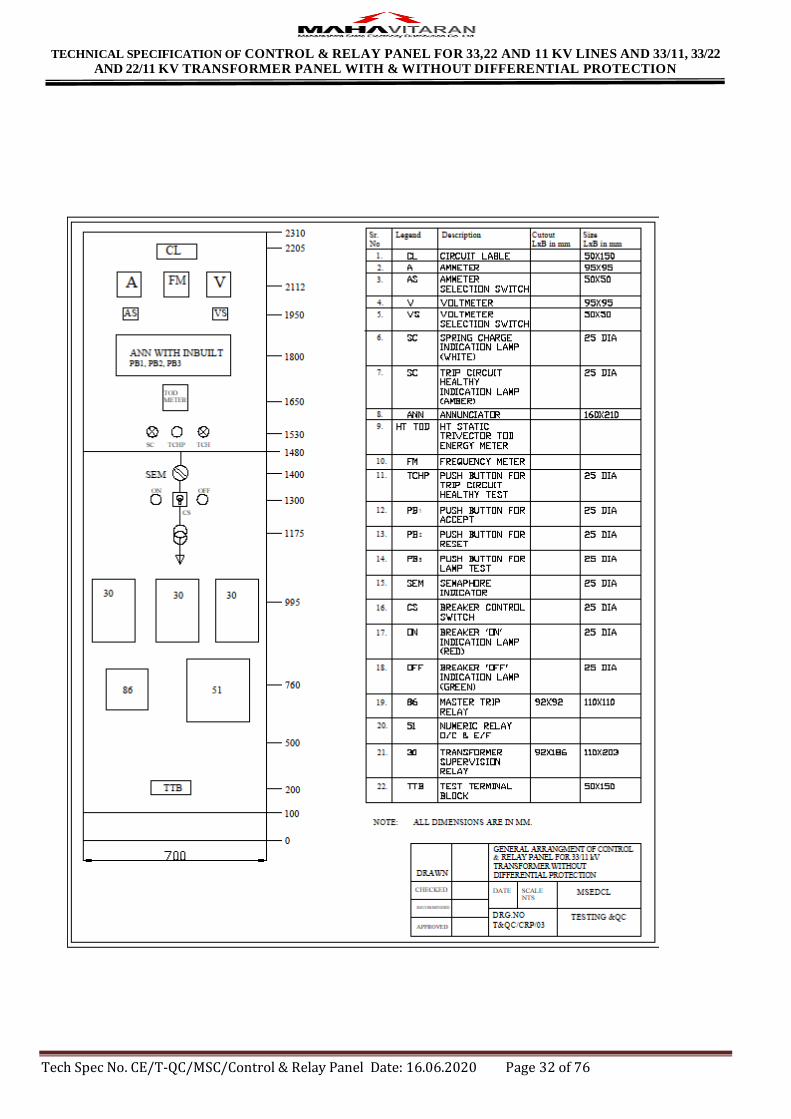
Annexure C -Drawings of Control and Relay panel
Page 31
TECHNICAL SPECIFICATION OF CONTROL & RELAY PANEL FOR 33,22 AND 11 KV LINES AND 33/11, 33/22
AND 22/11 KV TRANSFORMER PANEL WITH & WITHOUT DIFFERENTIAL PROTECTION
Tech Spec No. CE/T-QC/MSC/Control & Relay Panel Date: 16.06.2020 Page 31 of 76
Page 32
TECHNICAL SPECIFICATION OF CONTROL & RELAY PANEL FOR 33,22 AND 11 KV LINES AND 33/11, 33/22
AND 22/11 KV TRANSFORMER PANEL WITH & WITHOUT DIFFERENTIAL PROTECTION
Tech Spec No. CE/T-QC/MSC/Control & Relay Panel Date: 16.06.2020 Page 32 of 76
Page 33
TECHNICAL SPECIFICATION OF CONTROL & RELAY PANEL FOR 33,22 AND 11 KV LINES AND 33/11, 33/22
AND 22/11 KV TRANSFORMER PANEL WITH & WITHOUT DIFFERENTIAL PROTECTION
Tech Spec No. CE/T-QC/MSC/Control & Relay Panel Date: 16.06.2020 Page 33 of 76
Page 34
TECHNICAL SPECIFICATION OF CONTROL & RELAY PANEL FOR 33,22 AND 11 KV LINES AND 33/11, 33/22
AND 22/11 KV TRANSFORMER PANEL WITH & WITHOUT DIFFERENTIAL PROTECTION
Tech Spec No. CE/T-QC/MSC/Control & Relay Panel Date: 16.06.2020 Page 34 of 76
Page 35
TECHNICAL SPECIFICATION OF CONTROL & RELAY PANEL FOR 33,22 AND 11 KV LINES AND 33/11, 33/22
AND 22/11 KV TRANSFORMER PANEL WITH & WITHOUT DIFFERENTIAL PROTECTION
Tech Spec No. CE/T-QC/MSC/Control & Relay Panel Date: 16.06.2020 Page 35 of 76
Annexure D
GUARANTEED TECHNICAL PARTICULARS
33, KV INDOOR CONTROL & RELAY PANEL FOR TRANSFORMER WITH DIFFERENTIAL PROTECTION
Sr.
No. GTP PARAMETERS SUPPLIER CONFIRMATIONS
1 MAKE OF PANEL :
2 Type of Panel-Simplex :
3 Overall dimensions (H x W x D) of panel shall be
2310mmx700mmx750mm :
4 Thickness of Sheet Steel shall not be less than 3 mm for
front panel :
5 Thickness of Sheet Steel shall not be less than 2 mm for
doors of panel :
6 Thickness of Sheet Steel shall not be less than 2 mm for
sides of panel :
7 Thickness of Sheet Steel shall not be less than 2 mm for
top portion of panel :
8 Thickness of Sheet Steel shall not be less than 2 mm for
bottom portion of panel :
9 Final painting of panels shall be done with Light Grey
color to shade no.631 as per IS-5, for interior. (Yes/No) :
10 Final painting of panels shall be done with Light Grey
color to shade no.631 as per IS-5, for exterior. (Yes/No) :
11 Mimic section shall have Brilliant green paint to shade
No.221 of IS 5 for 33 kV (Yes/No) :
12 C&R Panel for Transformer with differential protection
panel shall have I circuits (Yes/No) :
13 Wiring through shall be used for routing cables (Yes/No) :
14 The panels shall provide degree of protection not less than
IP 30 in accordance with IS 12063/1987 :
15 Wiring numberings shall be as per IS 5578/1964 :
16 Terminal connectors shall be stud type, (Yes/No) :
17 Terminal connectors shall be made of Brass material.
(Yes/No) :
18 The conductor size shall be 2.5 mm (minimum) :
19 Whether equipment identification labels provided.
(Yes/No) :
20 OVER CURRENT & EARTH FAULT RELAY
A
Make of Non directional 3 Over Current & 1 Earth Fault
with high set relay.
:
Page 36
TECHNICAL SPECIFICATION OF CONTROL & RELAY PANEL FOR 33,22 AND 11 KV LINES AND 33/11, 33/22
AND 22/11 KV TRANSFORMER PANEL WITH & WITHOUT DIFFERENTIAL PROTECTION
Tech Spec No. CE/T-QC/MSC/Control & Relay Panel Date: 16.06.2020 Page 36 of 76
B Type of 3 Over Current & 1 Earth Fault relay.
:
C
Designation of 3 Over Current & 1 Earth Fault
relay.
:
D General design of 3 Over Current & I Earth Fault relay
:
E Reference Standards
:
F
Number of poles (elements) of 3 Over Current & 1 Earth
Fault relay.
:
G Auxiliary supply 30 VDC voltage required. :
H Relay operating characteristic :
I
Instantaneous O/C Settings
Instantaneous E/F Settings
:
J High Fault setting for Over Current :
K High Fault setting for Earth Fault
:
M Time Multiplier Setting for O/C & E/F
:
N
Memory storage capacity for fault information for latest
faults with date & time stamping, fault amplitude, type of
fault with FIFO feature
:
O
Number of output contacts of over Current & Earth Fault
relay shall be 2 trip and 2 alarm.
:
P
Current setting available 'for O/C & E/F elements of over
Current & Earth Fault relay shall be 50 % to 200% of
Base Current in steps of 1 %.
:
Q
Output contact rating of 3 Over Current & l Earth Fault
relay.
:
R
Current coil rating (Amps) of Over Current & Earth Fault
relay shall be 1 A
:
S Operational indicator of over Current & Earth Fault relay
shall be flag :
T
Mounting of Over Current & Earth Fault relay shall be
flush type
:
Page 37
TECHNICAL SPECIFICATION OF CONTROL & RELAY PANEL FOR 33,22 AND 11 KV LINES AND 33/11, 33/22
AND 22/11 KV TRANSFORMER PANEL WITH & WITHOUT DIFFERENTIAL PROTECTION
Tech Spec No. CE/T-QC/MSC/Control & Relay Panel Date: 16.06.2020 Page 37 of 76
U LED Indications for power ON, pickup, Trip & High fault
:
V Communication port RS 485 is provided (Yes/No) :
W Password protection provided (Yes/No)
:
X Communication Protocol
:
Y
Whether any special equipment / tools required for testing
/ maintenance of Over Current & Earth Fault relay.
:
Z Whether relay is type tested. (Yes/No) :
21
HIGH SPEED TRIP RELAY ( MASTER TRIP
RELAY)
A Reference Standard
:
B Make of High-Speed Trip Relay
:
C Type & Designation of Mater trip Relay
:
D
General design of Trip Relays shall be electromechanical.
(Yes/No)
:
E Coil rating (voltage) of Master Trip Relays
shall be 30 VDC :
F VA Burden of Master Trip Relays
:
G
Operating time of Trip Relays shall be 25 ms at nominal
rated voltage.
:
H Number of output contacts of Trip Relays :3 NO + 2 NC
:
I
Type of indication of Trip Relays shall be hand reset type
mechanical flag in
:
J Contact rating of Master Trip Relay
:
K Mounting of Master Trip Relays shall be flush type :
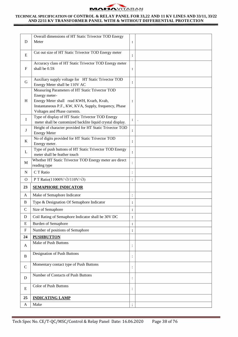
22 HT STATIC TRIVECTOR TOD ENERGY METER
A Reference standard
:
B
Make & Category of HT Static Trivector TOD Energy
meter(category C1-DLMS)
:
C Type of HT Static Trivector TOD Energy Meter
:
Page 38
TECHNICAL SPECIFICATION OF CONTROL & RELAY PANEL FOR 33,22 AND 11 KV LINES AND 33/11, 33/22
AND 22/11 KV TRANSFORMER PANEL WITH & WITHOUT DIFFERENTIAL PROTECTION
Tech Spec No. CE/T-QC/MSC/Control & Relay Panel Date: 16.06.2020 Page 38 of 76
D
Overall dimensions of HT Static Trivector TOD Energy
Meter
:
E Cut out size of HT Static Trivector TOD Energy meter
:
F
Accuracy class of HT Static Trivector TOD Energy meter
shall be 0.5S
:
G Auxiliary supply voltage for HT Static Trivector TOD
Energy Meter shall be 110V AC :
H
Measuring Parameters of HT Static Trivector TOD
Energy meter-
Energy Meter shall read KWH, Kvarh, Kvah,
Instantaneous P.F., KW, KVA, Supply, frequency, Phase
Voltages and Phase currents.
:
I Type of display of HT Static Trivector TOD Energy
meter shall be customized backlite liquid crystal display. : .
J Height of character provided for HT Static Trivector TOD
Energy Meter :
K No of digits provided for HT Static Trivector TOD
Energy meter. :
L Type of push buttons of HT Static Trivector TOD Energy
meter shall be feather touch :
M Whether HT Static Trivector TOD Energy meter are direct
reading type :
N C T Ratio :
O P T Ratio(11000V/√3/110V/√3) :
23 SEMAPHORE INDICATOR
A Make of Semaphore Indicator :
B Type & Designation Of Semaphore Indicator :
C Size of Semaphore :
D Coil Rating of Semaphore Indicator shall be 30V DC :
E Burden of Semaphore :
F Number of positions of Semaphore :
24 PUSHBUTTON
A Make of Push Buttons
:
B Designation of Push Buttons
:
C Momentary contact type of Push Buttons
:
D Number of Contacts of Push Buttons
:
E Color of Push Buttons
:
25 INDICATING LAMP
A Make ;
Page 39
TECHNICAL SPECIFICATION OF CONTROL & RELAY PANEL FOR 33,22 AND 11 KV LINES AND 33/11, 33/22
AND 22/11 KV TRANSFORMER PANEL WITH & WITHOUT DIFFERENTIAL PROTECTION
Tech Spec No. CE/T-QC/MSC/Control & Relay Panel Date: 16.06.2020 Page 39 of 76
B Type :
C
Rating
a. Current
b. Voltage
c. Watts
:
:
:
D Life of Lamp in burning hours :
E Withstand Voltage :
F Indicating Lamp Color:
G
a. Close indication (CB/ISOLATOR/ES)
b. Open indication (CB/ISOLATOR/ES)
c. CB Auto Trip
d. CB Spring Charged
:
:
:
:
26 TRANSFORMER DIFFERENTIAL RELAY
A Make of Transformer Differential Relay
:
B Type designations of Transformer Differential Relay
:
C Whether percentage biased type :
D Whether built-in highest units available
: .
E
Transformer Differential Relay shall be suitable for 30V
DC
:
F C.T. Rating of Transformer Differential Relay
:
G No. of I/P & O/P contact :
H Output Contact Rating of Transformer Differential Relay :
I Type of Operation indicator of Transformer Differential
Relay :
27 AUXILIARY RELAY FOR TRAFO. FAULTS
A Make of Auxiliary Relay for T/F Fault Supervision :
B Type & Designation of Auxiliary Relay for Transformer
Fault Supervision :
C General design of Relay shall be electromechanical :
D Number of Elements of Aux Relay for Transformer Fault
Supervision :
E DC rating (voltage) shall be 30 VDC :
F VA Burden :
G Operating time shall be instantaneous at rated voltage. :
H No. of output contacts 4 pairs of Hand reset. :
I
Type of indication shall be hand reset type mechanical flag
in window
:
Page 40
TECHNICAL SPECIFICATION OF CONTROL & RELAY PANEL FOR 33,22 AND 11 KV LINES AND 33/11, 33/22
AND 22/11 KV TRANSFORMER PANEL WITH & WITHOUT DIFFERENTIAL PROTECTION
Tech Spec No. CE/T-QC/MSC/Control & Relay Panel Date: 16.06.2020 Page 40 of 76
J Contact rating of Master Trip Relay
:
K Mounting shall be flush type
:
28 ANNUNCIATOR
A Make of Annunciator
:
B Type of Annunciator
:
C General design of Annunciator shall be Static (Yes/ No.)
:
D Number of Windows in Annunciator
:
E No. of LED per window for Annunciator
:
F Whether Annunciator Relays of Annunciator is built in. :
G DC rating of Annunciator shall be 30VDC :
H Burden per window in mA :
29 AMMETER
A Make of Ammeter :
B Type of Ammeter :
C Accuracy of Ammeter shall be 1% of FSD :
D Size of Ammeter shall be 48 x 96 sq. mm. :
E Response time of ammeter shall be 1 Sec :
F Operating Temp. of Ammeter Shall be up to 55° C :
G Dielectric strength of Ammeter shall be 2 kV RMS for I
minute. :
H Power Consumption of Ammeter shall be less than 3 VA :
I Ammeter shall be suitable for 50Hz frequency :
J Operating current of Ammeter shall be 1 A :
30 AMMETER SELECTOR SWITCH
A Make of Ammeter Selector Switch :
B Type of Ammeter Selector Switch :
C Size of Ammeter Selector Switch :
Page 41
TECHNICAL SPECIFICATION OF CONTROL & RELAY PANEL FOR 33,22 AND 11 KV LINES AND 33/11, 33/22
AND 22/11 KV TRANSFORMER PANEL WITH & WITHOUT DIFFERENTIAL PROTECTION
Tech Spec No. CE/T-QC/MSC/Control & Relay Panel Date: 16.06.2020 Page 41 of 76
D Rated insulation Voltage of Ammeter Selector Switch
shall be 660 volts :
E Rated Impulse Withstand Voltage be 6kV :
F Rated Operational Current be 12A :
31 VOLTMETER
A Make of Voltmeter :
B Type of Voltmeter :
C Acc. of Voltmeter shall be 1 %of FSD :
D Size of Voltmeter shall be 48 x 96 sq. mm.
:
E Response time of Voltmeter Shall be 1 second
:
F Operating Temp. of Voltmeter Shall be up to 55° C
:
G Power Consumption of Voltmeter shall be less than 3 VA
:
H Dielectric strength
:
I Voltmeter shall be suitable for 50 Hz Frequency :
32 VOLTMETER SELECTOR SWITCH
A Make Of Voltmeter Selector Switch :
B Type of Voltmeter Selector Switch :
C Size of Voltmeter Selector Switch :
D Rated insulation Voltage of Voltmeter Selector Switch
shall be 660 volts :
E Rated Impulse withstand voltage of Voltmeter Selector
Switch shall be 6 kV :
F Rated Operational Current be 12A :
33 FREQUENCY METER
A Make of Frequency Meter :
B Type of Frequency Meter :
C Power consumption of Frequency Meter shall be less than
6 VA :
D Dielectric strength of frequency meter shall be 2kV rms
for 1 minute. :
E Range of Freq. meter shall be 45 Hz to 55 Hz :
F Size of Frequency meter shall be 96 sq. mm. :
Page 42
TECHNICAL SPECIFICATION OF CONTROL & RELAY PANEL FOR 33,22 AND 11 KV LINES AND 33/11, 33/22
AND 22/11 KV TRANSFORMER PANEL WITH & WITHOUT DIFFERENTIAL PROTECTION
Tech Spec No. CE/T-QC/MSC/Control & Relay Panel Date: 16.06.2020 Page 42 of 76
Annexure -E-Technical specification for HT Static Trivector TOD Energy meter
1.00 SCOPE
This specification covers design; manufacture, testing, supply and delivery of ISI mark HT three phase four wire CT / PT operated 1 Amps or 5 Amps fully Static & AMR compatible TOD Tri - vector Energy Meter as per
Category C1 of IS: 15959 / 2011 amended upto date. The meters shall be suitable for measurement of Active
Energy (kWh), Reactive Energy (kVArh) Lag and (kVArh) Lead separately, Apparent Energy (kVAh), demand
(kW), demand (kVA), etc. as per Power tariff requirement for AC balanced / unbalanced loads of HT Consumers.
The meter shall conform in all respects to high standards of engineering, design and workmanship and shall be
capable of performing in continuous commercial operation, in a manner acceptable to purchaser, who will interpret
the meaning of drawings and specification and shall have the power to reject any work or material which, in his
judgment is not in accordance therewith. The offered material shall be complete with all components necessary for
their effective and trouble free operation. Such components shall be deemed to be within the scope of Bidder’s
supply irrespective of whether those are specifically brought out in these specifications and / or the commercial
order or not.
2.00 APPLICATION
For use on HT consumer installations.
3.00 SERVICE CONDITIONS
As per IS: 14697 / 1999 (amended up to date), the meter must perform satisfactorily under Non-Air Conditioned
environment (within stipulations of IS). The meters to be supplied against this specification shall be suitable for
satisfactory continuous operation under the following tropical conditions.
Environmental Conditions
(a) Maximum ambient temperature 550 C
(b) Maximum ambient temperature in shade 500 C
(c) Minimum temperature of air in shade 50 C
(d) Maximum daily average temperature 400 C
(e) Maximum yearly weighted average temperature 320 C
(f) Relative Humidity 10 to 95 %
(g) Maximum Annual rainfall 1450 mm
(h) Maximum wind pressure 150 Kg/m2
(i) Maximum altitude above mean sea level 1000 mtrs
(j) Isoceraunic level 50 days/year
(k) Seismic level (Horizontal acceleration) 0.3 g
(l) Climate: Moderately hot and humid tropical climate conducive to rust and fungus growth.
4.00 STANDARD TO WHICH METER SHALL COMPLY
IS: 15959 / 2011 – Data Exchange for Electricity Meter Reading, Tariff and Load Control – Companion
Specification for Category – “C1” Meters amended upto date;
IS: 14697 / 1999 (amended up to date) – AC Static Transformer operated Watt-hour and VAR-hour Meters, Class
0.2S – Specification;
CBIP Tech Report 88 amended up to date for AC Static Transformer operated Watt Hour & VAR-Hour Meters
(class 0.2S);
Page 43
TECHNICAL SPECIFICATION OF CONTROL & RELAY PANEL FOR 33,22 AND 11 KV LINES AND 33/11, 33/22
AND 22/11 KV TRANSFORMER PANEL WITH & WITHOUT DIFFERENTIAL PROTECTION
Tech Spec No. CE/T-QC/MSC/Control & Relay Panel Date: 16.06.2020 Page 43 of 76
IS: 15707 / 2006 Specification for Testing, evaluation, installation & maintenance of AC Electricity Meters-Code of Practice;
CEA regulations and MERC guidelines with latest amendments.
The specifications given in this document supersedes the relevant clauses of IS: 14697 / 1999 (amended up to date)
wherever applicable.
The equipment meeting with the requirements of other authoritative standards, which ensures equal or better
quality than the standards mentioned above, also shall be considered.
In case the bidder wishes to offer material conforming to the other authoritative standards, salient points of
difference between the standards adopted and the specific standards shall be clearly brought out in relevant
schedule.
Copy of such standards with authentic English Translations, shall be furnished along with the offer.
In case of conflict related with communication protocol, the IS: 15959 / 2011 – Data Exchange for Electricity
Meter Reading, Tariff and Load Control – Companion Specification shall prevail upon.
For conflict related with other parts of the specification, the order of priority shall be – (i) this technical
specification, (ii) IS: 14697 / 1999 (Amended up to date), (iii) IEC, (iv) other authoritative standards.
In case of any difference between provisions of these standards, the provisions of this specification shall prevail.
5.00 GENERAL TECHNICAL REQUIREMENT
1)
TYPE
Three Phase, Four Wire 1 Amp or 5 Amps fully Static
AMR compatible TOD Tri - Vector Energy Meter with
Optical & RS 232 Port as per Category C1 of IS: 15959 / 2011 (with DLMS protocol) for use on HT Consumers
installation.
2) FREQUENCY 50 Hz ±5%
3) ACCURACY CLASS 0.2S (FOR ACTIVE AND REACTIVE ENERGY)
4) PT SECONDARY
VOLTAGE 63.5 V Ph-N
5) RATED VOLTAGE 110 V Ph-Ph or 3 x 63.5 V Ph-N
6) VOLTAGE RANGE +15% to – 30% of rated voltage.
7) PT RATIO 11 kV/
8) CT RATIO 1 / 1 Amps; 5 / 5 Amps
9) BASIC CURRENT (Ib) 1 Amp; 5 Amps.
10) MAXIMUM CONTINUOUS
CURRENT ( Imax )
2 times (200 %) of Ib.
11) SHORT TIME CURRENT As per IS: 14697 / 1999.
12) STARTING CURRENT 0.1% of Ib.
13) POWER CONSUMPTION
The active and apparent power consumption, in each
voltage circuit, at reference voltage, reference
temperature and reference frequency shall not exceed
1.0 W and 4 VA.
1 √3
110 V
√3
Page 44
TECHNICAL SPECIFICATION OF CONTROL & RELAY PANEL FOR 33,22 AND 11 KV LINES AND 33/11, 33/22
AND 22/11 KV TRANSFORMER PANEL WITH & WITHOUT DIFFERENTIAL PROTECTION
Tech Spec No. CE/T-QC/MSC/Control & Relay Panel Date: 16.06.2020 Page 44 of 76
The apparent power taken by each current circuit, at
basic current Ib, reference frequency and reference temperature shall not exceed 2 VA.
14) POWER FACTOR
Power Factor range: Zero Lag to unity to Zero Lead to
unity
Avg. P.F = Total( kWh)
Total (kVAh)
kVAh = √ (Kwh )2 + (RKVAhlag + RKVAhlead )2
15) DESIGN
Meter shall be designed with application specific
integrated circuit (ASIC) or micro controller; shall have
no moving parts; electronic components shall be
assembled on printed circuit board using surface
mounting technology; factory calibration using high
accuracy (0.1 class) software based test bench.
16) POWER SUPPLY SMPS
17) ISI MARK The meter shall bear ISI Mark
18) TEMPERATURE
The standard reference temperature for performance shall
be 270 C. The mean temperature co-efficient shall not
exceed 0.03%.
6.00 CONSTRUCTIONAL REQUIREMENT
6.01 GENERAL MECHANICAL REQUIREMENT
The meter shall be designed and constructed in such a way as to avoid introducing any danger in normal use and
under normal conditions, so as to ensure especially:
(a) personal safety against electric shock:
(b) personal safety against effects of excessive temperature;
(c) safety against spread of fire;
(d) Protection against penetration of solid objects, dust and water.
(e) Detection of fraud / pilferage
6.02 The meter shall be projection type and shall be dust and moisture proof. All parts that are likely to develop
corrosion under normal working condition shall be effectively protected against corrosion by suitable method to
achieve durable results.
6.03 All insulating materials used in the construction of the meter shall be substantially non-hygroscopic, non ageing
and of tested quality.
6.04 METER CASE
6.04.01 The meter base & cover shall be made out of unbreakable, high grade, fire resistant Polycarbonate material
so as to give it tough and non-breakable qualities. Meter base shall be opaque and meter top cover shall be
transparent.
6.04.02 The poly carbonate body of the meter shall conform to IS: 11731 / 1986 (FV-2 Category) besides meeting the
test requirement of heat deflection test as per ISO 75, glow wire test as per the IS: 11000 (part 2/SEC-1)
2008 OR IEC PUB 60695-2-12, Ball pressure test as per IEC-60695-10-2 and Flammability Test as per UL
94 or as per IS: 11731 (Part-2) 1986.
6.04.03 The Poly-carbonate opaque base and transparent top cover of meter shall be ultra-sonically welded
(continuous welding) so that once the meter is manufactured and tested at factory; it shall not be possible to
open the cover at site except the terminal cover. The thickness of material for meter cover and base shall be 2
mm (minimum).
Page 45
TECHNICAL SPECIFICATION OF CONTROL & RELAY PANEL FOR 33,22 AND 11 KV LINES AND 33/11, 33/22
AND 22/11 KV TRANSFORMER PANEL WITH & WITHOUT DIFFERENTIAL PROTECTION
Tech Spec No. CE/T-QC/MSC/Control & Relay Panel Date: 16.06.2020 Page 45 of 76
6.04.04 The meter body shall be type tested for IP51 degree of protection as per IS: 12063 against ingress of dust,
moisture & vermin. The type test certificate shall be submitted along with the offer.
6.04.05 The meter cover shall be secured to base by means of sealable unidirectional captive screws with two holes.
6.05 TERMINALS & TERMINAL BLOCK
6.05.01 The terminal block shall be made from high quality non-hygroscopic, fire retardant, reinforced polycarbonate
/ non-Bakelite material which shall form an extension of the meter case.
6.05.02 The material of which the terminal block is made shall be capable of passing the tests given in IS: 1336O
(Part 6/Sec 17), ISO 75-1 (1993) & ISO 75-2 (1993) for a temperature of 1350C and a pressure of 1.8 MPa
(Method A).
6.05.03 The holes in the insulating material which form an extension of the terminal holes shall be of sufficient size
to also accommodate the insulation of the conductors.
6.05.04 The manner of fixing the conductors to the terminals shall ensure adequate and durable contact such that
there is no risk of loosening or undue heating.
6.05.05 Screw connections transmitting contact force and screw fixings which may be loosened and tightened several
times during the life of meter shall screw into metal nuts.
6.05.06 All parts of every terminal shall be such that the risk of corrosion resulting from contact with any other metal
part is minimized.
6.05.07 Electrical connections shall be so designed that contact pressure is not transmitted through insulating material
of the terminal block.
6.05.08 The terminals, the conductor fixing screws or the external or internal conductors shall not be liable to come
into contact with terminal covers.
6.05.09 Two screws shall be provided in each current & potential terminal for effectively clamping the external leads
or thimbles.
6.05.10 Each clamping screw shall engage a minimum of three threads in the terminal. The ends of screws shall be
such as not to pierce and cut the conductors used.
6.05.11 The minimum internal diameter of terminal hole shall be as per IS: 14697 / 1999 or CBIP Tech Report 88.
6.05.12 The manufacturer shall ensure that the supporting webs between two terminals of the terminal block shall be
sufficiently high to ensure that two neighboring terminals do not get bridged by dust and there shall not be
any possibility of flash over between adjacent terminals of the terminal block.
6.06 TERMINAL COVER
6.06.01 The termination arrangement shall be provided with an extended transparent terminal cover as per clause
number 6.5.2 of IS: 14697 / 1999 (amended upto date) irrespective of rear connections.
6.06.02 The terminal cover shall be made out of same material as that of meter body. The terminal cover shall be
unbreakable, high grade, fire resistant Polycarbonate material so as to give it tough and non-breakable
qualities. The terminal cover shall be transparent.
6.06.03 The terminal cover shall enclose the actual terminals, the conductor fixing screws and unless otherwise
specified, a suitable length of external conductors and their insulation.
6.06.04 The terminal cover shall be provided with one side hinge/two top hinges.
6.06.05 Independent sealing provision shall be made against opening of the terminal cover and meter body cover to
prevent unauthorized tampering. It is necessary to provide bidirectional screws with two holes for sealing
purpose of terminal cover. The meter shall be pilfer-proof & tamper-proof.
6.06.06 The fixing screws used on the terminal cover for fixing and sealing in terminal cover shall be held captive in
the terminal cover.
Page 46
TECHNICAL SPECIFICATION OF CONTROL & RELAY PANEL FOR 33,22 AND 11 KV LINES AND 33/11, 33/22
AND 22/11 KV TRANSFORMER PANEL WITH & WITHOUT DIFFERENTIAL PROTECTION
Tech Spec No. CE/T-QC/MSC/Control & Relay Panel Date: 16.06.2020 Page 46 of 76
6.06.07 Proper size of grooves shall be provided at bottom of this terminal cover for incoming service connections.
6.06.08 When the meter is mounted, no access to the terminals by any means shall be possible without breaking
seals(s) of the terminal cover.
6.07 RESISTANCE TO HEAT AND FIRE
The terminal block, the terminal cover and the meter case shall ensure reasonable safety against the spread of fire.
They shall not be ignited by thermal overload of live parts in contact with them.
6.08 The meter shall be completely factory sealed except the terminal block cover.
6.09 The provision shall be made on the meter for at least two seals to be put by utility user.
6.10 A Push button facility shall be provided for high resolution reading / alternate mode of display, as brought out
elsewhere in this specification. Facility of scrolling of all the readings up and down in all the display modes shall
be provided.
6.11 OUTPUT DEVICES
The meter shall have test output accessible from the front and be capable of being monitored with suitable testing
equipment while in operation at site. The operation indicator must be visible from front. The test output device shall
be provided in the form of blinking LED. Resolution of the test output device shall be sufficient to enable the
starting current test in less than 10 minutes. The pulse rate of output device which is Pulse / kWh, Pulse / kVArh and
Pulse/kVAh (meter constant) shall be programmed according to primary values of voltage & current & shall be
indelibly provided on the nameplate.
6.12 The meter accuracy shall not be affected by magnetic field (AC / DC / Permanent) upto 0.2 Tesla on all the sides of
meter, i.e. front, sides, top and bottom of the meter as per CBIP Technical Report 88 with latest amendments.
Under influence of any magnetic field (AC / DC / Permanent) above 0.2 Tesla, if the accuracy of the meter gets
affected, then the meter shall record energy considering Imax and reference voltage at unity power factor.
6.13 The meter shall also be capable to withstand and shall not get damaged if phase-to-phase voltage is applied between
phases & neutral for five minutes without affecting the accuracy.
6.14 In meter, power supply unit shall be micro control type instead of providing transformer and then conversion to
avoid magnetic influence.
6.15 Non specified display parameters in the meter shall be blocked and it shall not be accessible for reprogramming at
site. However these parameters shall be programmable at site through representative of meter manufacturer.
6.16 Complete metering system shall not be affected by the external electromagnetic interference such as electrical
discharge of cables and capacitors, harmonics, electrostatic discharges, external magnetic fields and DC current in
AC supply etc.
6.17 Internal CTs are to be provided with magnetic shielding and they shall be tested separately prior to assembly by the
meter manufacturer.
6.18 PCB used in meter shall be made by Surface Mounting Technology.
6.19 REAL TIME INTERNAL CLOCK (RTC)
The real time quartz clock shall be used in the meter for maintaining time (IST) and calendar. The RTC shall be non - rechargeable and shall be pre-programmed for 30 Years Day / date without any necessity for correction. The
maximum drift shall not exceed +/- 300 seconds per year.
The clock day / date setting and synchronization shall only be possible through password / Key code command from
one of the following:
a) Hand Held Unit (HHU), Laptop Computer or Meter testing work bench and this shall need password enabling
for meter;
b) From remote server through suitable communication network or Sub-station data logger ‘PC’.
The RTC battery & the battery for display in case of power failure shall be separate.
Page 47
TECHNICAL SPECIFICATION OF CONTROL & RELAY PANEL FOR 33,22 AND 11 KV LINES AND 33/11, 33/22
AND 22/11 KV TRANSFORMER PANEL WITH & WITHOUT DIFFERENTIAL PROTECTION
Tech Spec No. CE/T-QC/MSC/Control & Relay Panel Date: 16.06.2020 Page 47 of 76
6.20 The meter shall remain immune for the test of electromagnetic HF/RF defined under the test no. 4.0 for EMI/EMC
of IS 14697:1999 amended up to date.
6.21 For any higher signals than the present standards and MSEDCL technical specifications indicated above cl. 6.21,
the energy meters shall be immune & the accuracy of energy meters shall not get affected.
6.22 The communication of energy meters shall not be affected considering the above feature state in the clause 6.21 &
6.22.
6.23 The meter shall withstand any type of High Voltage and High Frequency surges which are similar to the surges
produced by induction coil type instruments without affecting the accuracy of the meter.
The accuracy of the meter shall not be affected with the application of abnormal voltage / frequency generating
device such as spark discharge of approximately 35 kV.
The meter shall be tested by feeding the output of this device to meter in any of the following manner for 10
minutes:
(i) On any of the phases or neutral terminals
(ii) On any connecting wires of the meter (Voltage discharge with 0-10 mm spark gap)
(iii) At any place in load circuit.
The accuracy of meter shall be checked before and after the application of above device.
6.24 SELF DIAGNOSTIC FEATURES
6.24.01 The meter shall keep log in its memory for unsatisfactory functioning or non-functioning of Real Time Clock
battery, also it shall be recorded and indicated in reading file at base computer software.
6.24.02 All display segments: "LCD Test" display shall be provided for this purpose.
6.25 The watch dog provided shall invariably protect the hanging of microprocessor during such type of tampering
devices.
6.26 METER PROTOCOL
The meter protocol shall be as per Annex E - Category C1 meters of IS: 15959 / 2011 amended upto date.
6.27 COMMUNICATION CAPABILITY
The meter shall be provided with two ports for communication of the measured / collected data as per IS: 15959 /
2011, i.e. a hardware port compatible with RS-232 specifications (RJ - 11 / RJ - 45 type is also acceptable) which
shall be used for remote access through suitable Pluggable Modem (4G/2G/3G/NB-IoT/PLCC/LPRF) and an
Optical port complying with hardware specifications detailed in IEC – 62056 - 21. This shall be used for local data
downloading through a DLMS compliant HHU. RS-232 port or TCP / IP port as required on terminal block is also
acceptable. Sealing arrangement for Optical & RS 232 port or TCP / IP port as required shall be provided.
During data communication process through either AMR or MRI, the meter energy recording should not get affected.
Both ports shall support the default and minimum baud rate of 9600 bps.
Necessary chord for Optical Port of minimum length of 1 metre in the ratio 25:1 shall be provided free of cost.
The minimum requirements for RS-232 based systems are described below:
i. The interface shall meet all the requirements of RS-232 specifications in terms of Physical media,
Network topologies, maximum devices, maximum distance, mode of operation, etc.
ii. RJ11 type connectors have to be provided to easily terminate the twisted pair.
Page 48
TECHNICAL SPECIFICATION OF CONTROL & RELAY PANEL FOR 33,22 AND 11 KV LINES AND 33/11, 33/22
AND 22/11 KV TRANSFORMER PANEL WITH & WITHOUT DIFFERENTIAL PROTECTION
Tech Spec No. CE/T-QC/MSC/Control & Relay Panel Date: 16.06.2020 Page 48 of 76
PIN DESCRIPTION
6.28 The meter shall have facility to read the default display parameters during Power supply failure. For this purpose an
internal battery may be provided.
The internal battery shall be Ni-mh or Li-ion or NI CD maintenance free battery of long life of 10 years. A suitable
Push Button arrangement for activation of this battery shall be provided.
6.29 WIRE / CABLE LESS DESIGN
The meter PCB shall be wireless to avoid improper and loose connections/ contacts.
6.30 Meter shall record & display total energy including Harmonic energy.
6.31 Reverse reading lock of main KWh and kVAh reading is to be incorporated with necessary software modification
if required additionally.
6.32 The data stored in the meters shall not be lost in the event of power failure. The meter shall have Non Volatile
Memory (NVM), which does not need any battery backup. The NVM shall have a minimum retention period of 10
years.
7.00 TOD TIMINGS
There shall be provision for at least 6 (SIX) TOD time zones for energy and demand. The number and timings of
these TOD time zones shall be programmable by manufacturer both at site / factory.
At present the time zones shall be programmed as below:
ZONE “A” (TZ1): 0000 Hrs to 0600 Hrs and 2200 Hrs to 2400 Hrs.
ZONE “B” (TZ2): 0600 Hrs to 0900 Hrs and 1200 Hrs to 1800 Hrs.
ZONE “C” (TZ3): 0900 Hrs to 1200 Hrs.
ZONE “D” (TZ4): 1800 Hrs to 2200 Hrs.
8.00 DEMAND INTEGRATION PERIOD
The maximum demand integration period shall be set at 30 minutes sliding window method (Sub Integration
period of 10 minutes) and can be set at 15 minutes programmable (Sub Integration period of 5 minutes), if required
in future.
9.00 MD RESET
The meter shall have following MD resetting options.
i) Communication driven reset;
ii) Manual resetting arrangement with sealing facility;
iii) Automatic reset at the end of certain predefined period (say, end of the month).
10.00 TAMPER AND FRAUD MONITORING FEATURES
10.01 ANTI TAMPER FEATURES.
The meter shall detect and correctly register energy under following tamper conditions:
(a) The meter accuracy shall not be affected by change of phase sequence. It shall maintain the desired accuracy
Pin No Signal
1 RTS (Ready To Send)
2 Ground (GND)
3 Transmit Data (Tx)
4 Receive Data (Rx)
Page 49
TECHNICAL SPECIFICATION OF CONTROL & RELAY PANEL FOR 33,22 AND 11 KV LINES AND 33/11, 33/22
AND 22/11 KV TRANSFORMER PANEL WITH & WITHOUT DIFFERENTIAL PROTECTION
Tech Spec No. CE/T-QC/MSC/Control & Relay Panel Date: 16.06.2020 Page 49 of 76
in case of reversal of phase sequence.
(b) The meter shall continue to work even without neutral.
(c) The meter shall work in absence of any two phases i.e. it shall work on any one phase wire and neutral, to record
relevant energy.
(d) If the accuracy of the meter gets affected under the influence of magnetic field more than 0.2 Tesla, then the same
shall be recorded as magnetic tamper event with date & time stamping and the meter shall record energy
considering the maximum value current (Imax) at ref. voltage and unity PF in all the three phases.
(e) If a consumer tries to steal power by disconnecting the voltage supply of one or two phases of the meter externally
or by tampering so that no voltage or partial voltage ( 50% of Vref) is available to voltage circuit of meter &
current is flowing in that phase, the meter shall record energy (kVAh & kWh) at Vref, current available in these
phases & unity power factor.
(f) The meter shall remain immune for the test of electromagnetic HF/RF defined under the test no. 4.0 for EMI/EMC
of IS 14697:1999 amended up to date. For any higher signals than the present standards and MSEDCL technical
specifications indicated above, the energy meters shall be immune & the accuracy of energy meter shall not get
affected.
The separate slot with 10 no. occurrences of EMI/EMC tamper along with date & time stamp shall be provided.
10.02 TAMPER EVENTS
10.02.01 The meter shall work satisfactorily under presence of various influencing conditions like External Magnetic Field,
Electromagnetic Field, Radio Frequency Interference, Harmonic Distortion, Voltage / Frequency Fluctuations and
Electromagnetic High Frequency Fields, etc. as per relevant IS.
10.02.02 The meter shall record the occurrence and restoration of tamper events of current, voltages, kWh, kVAh power
factor, event code, date & time etc. listed in Table 32 to 37 of IS: 15959 / 2011.
10.02.03 In the event the meter is forcibly opened, even by 2 to 4 mm variation of the meter cover, same shall be recorded
as tamper event with date & time stamping as per table 37 of IS: 15959 / 2011 and the meter shall continuously
display that the cover has been tampered.
10.02.04 The detection of the tamper event shall be registered in the tamper event register. The no. of times the tampering
has been done shall also be registered in the meter.
10.02.05 Tamper details shall be retrieved by authorized personnel through either of the following:
i) HHU.
ii) Remote access through suitable communication network.
10.02.06 Minimum 200 numbers of events (occurrences & restoration with date & time) shall be available in the meter
memory. The recording of abnormal events shall be on FIFO basis. The unrestored events shall be recorded
separately and shall not be deleted till they get recovered (permissible upto 3 months).
All the information of data shall be made available in simple & easy to understand format.
10.03 The threshold values for various tampers are as below.
Sr.
No. Description
Occurrence (With
Occ. Time 5 min.)
Restoration (With Rest.
Time 5 min.)
1. PT link Missing
(Missing potential)
50% of Vref and
current in that phase is
1% Ib
50 % of Vref
2. Over voltage in any phase 115 % of Vref 115 % of Vref
3. Low voltage in any phase 70 % of Vref 70 % of Vref
Page 50
TECHNICAL SPECIFICATION OF CONTROL & RELAY PANEL FOR 33,22 AND 11 KV LINES AND 33/11, 33/22
AND 22/11 KV TRANSFORMER PANEL WITH & WITHOUT DIFFERENTIAL PROTECTION
Tech Spec No. CE/T-QC/MSC/Control & Relay Panel Date: 16.06.2020 Page 50 of 76
11.00 QUANTITIES TO BE MEASURED & DISPLAYED
The meter shall be capable of measuring and displaying the following electrical quantities within specified accuracy
limits for polyphase balanced or unbalanced loads:
a) Instantaneous Parameters such as phase and line voltages, currents, power factors, overall kVA, kW, kVAr, power
factor, frequency etc as per details given in the table below and IS: 15959 / 2011.
b) Block Load Profile Parameters such as kVAh, kWh, kVArh (lag), kVArh (lead), Maximum Demand (MD) in kW /
kVA / power factor / phase and line voltages / currents etc. as per details given in the table below and IS: 15959 /
2011.
c) Billing Profile Parameters such as cumulative energy kWh / cumulative kVAh / cumulative energy kVArh, etc. as
per details given in the table below and IS: 15959 / 2011.
In addition to above the meter shall also record the Name plate details, programmable parameters (readable as profile),
occurrence and restoration of tamper events along with the parameters (Table 30, 31 32, 33, 34, 35, 36, 37 & 39
respectively) of IS: 15959 / 2011.
Detail of category wise parameters requirement suitable for HT (CT / PT) consumer metering is given in following
tables of IS: 15959 / 2011.
Category C1 Parameter group Annexure Table No.
HT (CT / PT) consumers
Energy Meters
Instantaneous parameters 27
Block Load Profile parameters 28
Billing Profile Parameters 29
Name Plate details 30
Programmable Parameters 31
4. Voltage Unbalance
Vmax - Vmin
10 % Vmax
Vmax - Vmin
10 % Vmax
5. CT reverse Change in direction of
current
Current flow in forward
direction.
6. CT Open.
Zero Amps in one or
two phases and current
in at least 1 phase is
5% Ib for 15 minutes.
3 % Ib for 15 min in
the tampered phase for
15 min.
7. Current Unbalance. (Diff. of phase currents)
30 % Iref* for 15 min 30 % Iref* for 15 min
8. Current Bypass Bypass Current 50 %
Iref* for 15 min
Bypass Current 30 %
Iref* for 15 min
9. Over Current in any Phase 120 % Ib 120 % Ib
10. Influence of permanent magnet or
AC / DC electromagnet / permanent
magnet
Immediate 1 minute after removal
11. Neutral Disturbance -- --
12. Power failure Immediate Immediate
13. Very Low PF -- --
14. Meter Cover Opening (2 to 4 mm) Immediate (Occurance only)
Higher of 3 phase currents shall be taken as reference for this purpose.
Page 51
TECHNICAL SPECIFICATION OF CONTROL & RELAY PANEL FOR 33,22 AND 11 KV LINES AND 33/11, 33/22
AND 22/11 KV TRANSFORMER PANEL WITH & WITHOUT DIFFERENTIAL PROTECTION
Tech Spec No. CE/T-QC/MSC/Control & Relay Panel Date: 16.06.2020 Page 51 of 76
Event Conditions 32 to 37
All logging parameters for
each of the event condition for 3 Ф / 4W
Capture parameters for event (Event Log
Profile) 39
12.00 DISPLAY OF MEASURED VALUES
12.01 DISPLAY INDICATORS
The supply indication shall be displayed permanently by LCD as a minimum and shall be visible from the front of the
meter. In case of non available of voltage to any phase(s), the LCDs of that particular phase shall stop glowing or those particular indicator(s) shall start blinking on the LCD display of meter.
12.02 Permanently backlit LCD panel shall show the relevant information about the parameters to be displayed. The
corresponding non-volatile memory shall have a minimum retention time of 10 years.
In the case of multiple values presented by a single display it shall be The meter shall have 6 digits (with +/- indication), parameter identifier, permanently backlit Liquid Crystal Display (LCD) with wide viewing angle. The size of digit shall
be minimum 8x5 mm. The decimal units shall not be displayed in auto scroll mode. However it shall be displayed in
push button mode or alternate mode for high resolution display for testing. Auto display cycling push button is required
with persistence time of 10 Seconds. LCD shall be suitable for temperature withstand of 700 C; adequate back up
arrangement for storing of energy registered at the time of power interruption shall be provided.
12.03 The meters shall be pre-programmed for following details.
a) PT Ratio: kV/ V
b) CT Ratio: 1/1 Amps or 5/5 Amps as per requirement.
c) MD resetting shall be auto as per clause no. 9.00 (iii).
d) MD Integration Period is 30 Minutes real time based.
e) Average power factor with 3 decimal digits shall be displayed.
f) The array of data to be retained inside the meter memory shall be for the last 60 days for a capture period of 30
minutes and 45 days for 15 minutes. Load survey data shall be first in first out basis (FIFO).
g) The display of various parameters in Normal Mode & Alternate mode shall be as per table 27 & 29 (except 8 & 9)
of Annex E of IS: 15959 / 2011 in the sequence as below. Display other than specified below shall be blocked. The
scroll period for auto scroll shall be 10 secs.
SN PARAMETERS
A NORMAL DISPLAY (DEFAULT DISPLAY)
1. LCD Test
2. Real Time Clock – Date & Time
3. Voltage – VR
4. Voltage – VY
5. Voltage – VB
6. Current – IR
7. Current – IY
11
√3
110
√3
Page 52
TECHNICAL SPECIFICATION OF CONTROL & RELAY PANEL FOR 33,22 AND 11 KV LINES AND 33/11, 33/22
AND 22/11 KV TRANSFORMER PANEL WITH & WITHOUT DIFFERENTIAL PROTECTION
Tech Spec No. CE/T-QC/MSC/Control & Relay Panel Date: 16.06.2020 Page 52 of 76
8. Current – IB
9. Cumulative Energy – kWh
10. Cumulative Energy – kWh - TOD Zone A (TZ1)
11. Cumulative Energy – kWh - TOD Zone B (TZ2)
12. Cumulative Energy – kWh - TOD Zone C (TZ3)
13. Cumulative Energy – kWh - TOD Zone D (TZ4)
14. Cumulative Energy – kVArh - Lag
15. Cumulative Energy – kVArh - Lag- TOD Zone A (TZ1)
16. Cumulative Energy – kVArh - Lag- TOD Zone B (TZ2)
17. Cumulative Energy – kVArh - Lag- TOD Zone C (TZ3)
18. Cumulative Energy – kVArh - Lag- TOD Zone D (TZ4)
19. Cumulative Energy –kVArh - Lead
20. Cumulative Energy – kVArh - Lead- TOD Zone A (TZ1)
21. Cumulative Energy – kVArh - Lead- TOD Zone B (TZ2)
22. Cumulative Energy – kVArh - Lead- TOD Zone C (TZ3)
23. Cumulative Energy – kVArh - Lead- TOD Zone D (TZ4)
24. Cumulative Energy – kVAh
25. Cumulative Energy – kVAh - TOD Zone A (TZ1)
26. Cumulative Energy – kVAh - TOD Zone B (TZ2)
27. Cumulative Energy – kVAh - TOD Zone C (TZ3)
28. Cumulative Energy – kVAh – TOD Zone D (TZ4)
29. Current MD – kVA with occurance date & time
30. MD - kVA – TOD Zone A (TZ1) with occurance date & time
31. MD - kVA – TOD Zone B (TZ2) with occurance date & time
32. MD - kVA – TOD Zone C (TZ3) with occurance date & time
33. MD - kVA – TOD Zone D (TZ4) with occurance date & time
34. Number of MD – kVA reset
Page 53
TECHNICAL SPECIFICATION OF CONTROL & RELAY PANEL FOR 33,22 AND 11 KV LINES AND 33/11, 33/22
AND 22/11 KV TRANSFORMER PANEL WITH & WITHOUT DIFFERENTIAL PROTECTION
Tech Spec No. CE/T-QC/MSC/Control & Relay Panel Date: 16.06.2020 Page 53 of 76
35. Rising MD with elapsed time
36. Three Phase Power Factor – PF
37. Cumulative Tamper Count
38. Meter Cover Opening – Occurance with date and time.
B ON DEMAND DISPLAY (ALTERNATE MODE)
1. Last date & time of MD - kVA reset
2. Current – IR
3. Current – IY
4. Current – IB
5. Voltage – VR
6. Voltage – VY
7. Voltage – VB
8. Signed Power Factor – R Phase
9. Signed Power Factor – Y Phase
10. Signed Power Factor – B Phase
11. Frequency
12. High resolution kWh (for calibration)
13. High resolution kVArh Lag(for calibration)
14. High resolution kVArh Lead(for calibration)
15. High resolution kVAh (for calibration)
16. Running Demand kVA (for calibration)
17. M1 MD - kVA – TOD Zone A (TZ1) with occurance date & time
18. M1 MD - kVA – TOD Zone B (TZ2) with occurance date & time
19. M1 MD - kVA – TOD Zone C (TZ3) with occurance date & time
20. M1 MD - kVA – TOD Zone D (TZ4) with occurance date & time
21. M2 MD - kVA – TOD Zone A (TZ1) with occurance date & time
22. M2 MD - kVA – TOD Zone B (TZ2) with occurance date & time
Page 54
TECHNICAL SPECIFICATION OF CONTROL & RELAY PANEL FOR 33,22 AND 11 KV LINES AND 33/11, 33/22
AND 22/11 KV TRANSFORMER PANEL WITH & WITHOUT DIFFERENTIAL PROTECTION
Tech Spec No. CE/T-QC/MSC/Control & Relay Panel Date: 16.06.2020 Page 54 of 76
h) Other KVA MD values shall be available in reset backup data for 12 months.
i) The meter display shall return to Default Display mode (mentioned above) if the 'Push button' is not operated for 15
seconds.
13.00 BILLING DATA, BILLING HISTORY & BLOCK LOAD SURVEY
13.01 BILLING DATA
The billing data shall be as per table 29 of Annex E of IS: 15959 / 2011 for category C1 and is summarised as below.
Sr. No. Parameters
1. Billing Date
2. System Power Factor for Billing Period
3. Cumulative Energy – kWh
4. Cumulative Energy – kWh - TOD Zone A (TZ1)
5. Cumulative Energy – kWh - TOD Zone B (TZ2)
6. Cumulative Energy – kWh - TOD Zone C (TZ3)
7. Cumulative Energy – kWh - TOD Zone D (TZ4)
8. Cumulative Energy – kVArh – Lag
9. Cumulative Energy – kVArh - Lag- TOD Zone A (TZ1)
10. Cumulative Energy – kVArh - Lag- TOD Zone B (TZ2)
11. Cumulative Energy – kVArh - Lag- TOD Zone C (TZ3)
12. Cumulative Energy – kVArh - Lag- TOD Zone D (TZ4)
13. Cumulative Energy – kVArh – Lead
14. Cumulative Energy – kVArh - Lead- TOD Zone A (TZ1)
15. Cumulative Energy – kVArh - Lead- TOD Zone B (TZ2)
16. Cumulative Energy – kVArh - Lead- TOD Zone C (TZ3)
17. Cumulative Energy – kVArh - Lead- TOD Zone D (TZ4)
18. Cumulative Energy – kVAh
23. M2 MD - kVA – TOD Zone C (TZ3) with occurance date & time
24. M2 MD - kVA – TOD Zone D (TZ4) with occurance date & time
25. Last Tamper Event with date and time.
Page 55
TECHNICAL SPECIFICATION OF CONTROL & RELAY PANEL FOR 33,22 AND 11 KV LINES AND 33/11, 33/22
AND 22/11 KV TRANSFORMER PANEL WITH & WITHOUT DIFFERENTIAL PROTECTION
Tech Spec No. CE/T-QC/MSC/Control & Relay Panel Date: 16.06.2020 Page 55 of 76
19. Cumulative Energy – kVAh - TOD Zone A (TZ1)
20. Cumulative Energy – kVAh – TOD Zone B (TZ2)
21. Cumulative Energy – kVAh – TOD Zone C (TZ3)
22. Cumulative Energy – kVAh – TOD Zone D (TZ4)
23. MD – kVA with occurance date & time
24. MD – kVA – TOD Zone A (TZ1) with occurance date & time
25. MD – kVA – TOD Zone B (TZ2) with occurance date & time
26. MD – kVA – TOD Zone C (TZ3) with occurance date & time
27. MD – kVA – TOD Zone D (TZ4) with occurance date & time
28. MD – kW occurance date & time
29. MD – kW – TOD Zone A (TZ1) with occurance date & time
30. MD – kW – TOD Zone B (TZ2) with occurance date & time
31. MD – kW – TOD Zone C (TZ3) with occurance date & time
32. MD – kW – TOD Zone D (TZ4) with occurance date & time
13.02 BILLING HISTORY
The meter shall have sufficient non-volatile memory for recording history of billing parameters for last 12 months.
13.03 BLOCK LOAD SURVEY
The Block Load survey data shall be logged on non time based basis, i.e. if there is no power for more than 24 hours,
the day shall not be recorded. Whenever meter is taken out and brought to laboratory, the load survey data shall be
retained for the period of actual use of meter. This load survey data can be retrieved as and when desired and load
profiles shall be viewed graphically / analytically with the help of meter application software. The meter application
software shall be capable of exporting / transmitting these data for analysis to other user software in spreadsheet
(excel) format.
The Block Load survey data shall be for specified parameters as per table 28 (except 8 & 9) for 3Ф/4W system of
measurement with NEUTRAL as reference point of Annex E of IS: 15959 / 2011. The specified parameters are as below.
Sr. No. Parameters
1. Real Time Clock – Date and Time
2. Current - IR
3. Current – IY
4. Current – IB
5. Voltage – VRN
Page 56
TECHNICAL SPECIFICATION OF CONTROL & RELAY PANEL FOR 33,22 AND 11 KV LINES AND 33/11, 33/22
AND 22/11 KV TRANSFORMER PANEL WITH & WITHOUT DIFFERENTIAL PROTECTION
Tech Spec No. CE/T-QC/MSC/Control & Relay Panel Date: 16.06.2020 Page 56 of 76
6. Voltage – VYN
7. Voltage – VBN
8. Block Energy – kWh
9. Block Energy – kVArh – Lag
10. Block Energy – kVArh – Lead
11. Block Energy – kVAh
14.00 DEMONSTRATION
The purchaser reserves the right to ask to give the demonstration of the equipment offered at the purchaser’s place.
15.00 PERFORMANCE UNDER INFLUENCE QUANTITIES
The meters performance under influence quantities shall be governed by IS: 14697 / 1999 (amended upto date) and
CBIP Tech. Report 88. The accuracy of meter shall not exceed the permissible limits of accuracy as per standard IS:
14697 / 1999 (amended upto date). In case of conflict, the priority shall be as per clause no. 5.00 of this specification.
16.00 HAND HELD UNIT (HHU)
16.01 To enable local reading of meters data, a DLMS compliant HHU shall be provided.
16.02 The HHU shall be as per specification given in Annex J of IS: 15959 / 2011.
16.03 It shall be compatible to the DLMS compliant energy meters that are to be procured / supplied on the basis of this
specification.
16.04 The HHU shall be supplied by the meter manufacturer along with the meter free of cost in the ratio of one for each 250
Nos. meters supplied including user manual and a set of direct communication cords for data downloading to the Laptop
or PC for each HHU and communication cord for downloading data from optical port to HHU shall be provided.
16.05 There shall be a provision for auto power save on HHU, which shall force the instrument in the power saving mode in
case of no-activity within 5 minutes. The data shall not be lost in the event the batteries are drained or removed from the
HHU.
16.06 The HHU shall have a memory capacity of 512 MB SRAM (Static RAM) with battery backup & upgradeable and BIOS
/ OS on FLASH / EEPROM Memory of 256 KB (RAM-512 MB, FLASH-2GB, SD Card- 8GB with USB facility.
16.07 The manufacturer / supplier shall modify the compatibility of HHU with the meter and the base computer system due to
any change in language or any other reasons at their own cost within guarantee period.
16.08 The HHU shall be type tested for (a) Tests of Mechanical requirement such as Free fall test, Shock Test, Vibration test,
(b) Tests of Climatic influences such as Tests of Protection against Penetration of Dust and Water (IP 6X), Dry Heat
test, Cold Test, Damp Heat Cyclic Test, (c) Tests for Electromagnetic Compatibility (EMC), (d) Test of Immunity to
Electromagnetic HF Fields and (e) Radio Interference Measurement.
16.09 The equipments offered shall be fully type tested at approved laboratory by National Accreditation Board for Testing
and Calibration Laboratories (NABL) as per relevant standards within last 5 years from the date of opening of tender &
the type test reports shall be enclosed with the offer.
17.00 COMPUTER SOFTWARE.
17.01 For efficient and speedy recovery of data downloaded through HHU on base computer, licensed copies of base
computer software shall have to be supplied free of cost. This software will be used at number of places up to Division
level. As many copies of base computer software as required up to Division level shall be provided by Supplier.
17.02 The meter shall be capable to communicate directly with laptop computer. Base Computer Software shall be suitable for
all types of printers such as dot matrix, inkjet, deskjet and laser printers.
Page 57
TECHNICAL SPECIFICATION OF CONTROL & RELAY PANEL FOR 33,22 AND 11 KV LINES AND 33/11, 33/22
AND 22/11 KV TRANSFORMER PANEL WITH & WITHOUT DIFFERENTIAL PROTECTION
Tech Spec No. CE/T-QC/MSC/Control & Relay Panel Date: 16.06.2020 Page 57 of 76
17.03 The Base Computer Software shall be "Windows” based & user friendly.The data transfer shall be highly reliable and
fraud proof (No editing shall be possible on base computer as well as HHU by any means). The software shall have
capability to convert all the data into ASCII format/XML format as per MIOS.
17.04 The Base Computer Software should be password protected.
17.05 The total time taken for downloading Billing, Tamper and Load Survey Data for 60 days shall be less than or equal to 5
minutes.
17.06 Downloading time of only Billing data shall be less than or equal to 20 secs.
17.07 The BCS software shall create one single file for the uploaded data, e.g. if CMRI contains the meter readings of, say,
2,000 consumer meters and the said data is uploaded to BCS, then the BCS shall create a single file containing separate
records for each consumer meter reading in ASCII format or XML file as per MIOS for individual meter reading.
17.08 Meter manufacturers should also need to submit Convert API (API3) as per MIOS universal standard along with Base
Computer System free of cost. This API should capable of converting both data i.e. AMR data collected from Read API
(API1) and MRI data collected from CMRI.
17.09 Also there shall be a provision to give filenames while creating the file.
17.10 As and when the meter manufacturer releases new or latest or advanced versions of meter hardware / firmware /
software (such as Base Computer System, API3 etc), the same shall be made available to purchaser immediately on the
release date free of cost. The latest version shall support all existing hardware / meters in the field. The meter
manufacturer should also provide support for changes and integration of Base Computer System and API3
17.11 The meter samples shall be tested by our IT Department for the time required for downloading the data as per
specifications and as confirmed by the bidder.
17.12 Downloading software shall also be provided so as to install on our Laptop for downloading data directly on Laptop
from meter without the use of HHU.
17.13 The software provided on laptop or PC shall be compatible to read the data from USB drive and for that purpose a
sample cable (1 No.) shall be provided with USB termination. USB being the de-facto standard, this is the requirement.
17.14 MSEDCL is procuring large quantity of meters. As such manufacturer have to depute Hardware Engineers and
Software Engineers on call basis, who shall have thorough knowledge of meter hardware / software used for
downloading and converting so as to discuss the problems, if any, or new development in the hardware / software with
Chief Engineer, Testing & Quality Control Cell / Chief General Manager (IT), MSEDCL, Prakashgad, Bandra (E),
Mumbai – 400051 without any additional charge.
18.00 CONNECTION DIAGRAM AND TERMINAL MARKINGS
The connection diagram of the meter shall be clearly shown on inside portion of the terminal cover and shall be of permanent nature. Meter terminals shall also be marked and this marking shall appear in the above diagram. The
diagram & terminal marking on sticker shall not be allowed.
19.00 NAME PLATE AND MARKING OF METERS
Meter shall have a name plate clearly visible, effectively secured against removal and indelibly and distinctly marked with
all essential particulars as per relevant standards. Meter Serial Number shall be Bar Coded along with numeric number.
The size of bar coded number shall not be less than 35x5 mm. The manufacturer’s meter constant shall be marked on the
name plate. Meter serial number & bar code on sticker will not be allowed.
The meter shall also store name plate details as given in the table 30 of Annex F of IS: 15959 / 2011. These shall be
readable as a profile as and when required.
In addition to the requirement as per IS, following shall be marked on the name plate.
(i) Purchase order no. & date
(ii) Month and Year of manufacture
(iii) Name of purchaser, i.e. MSEDCL
Page 58
TECHNICAL SPECIFICATION OF CONTROL & RELAY PANEL FOR 33,22 AND 11 KV LINES AND 33/11, 33/22
AND 22/11 KV TRANSFORMER PANEL WITH & WITHOUT DIFFERENTIAL PROTECTION
Tech Spec No. CE/T-QC/MSC/Control & Relay Panel Date: 16.06.2020 Page 58 of 76
(iv) Guarantee Five Years
(v) ISI mark
(vi) Category of Meter: Category C1 – HT (PT / CT) Consumer Meter. The lettering shall be bold in 3 mm font.
20.00 TESTS
20.01 TYPE TESTS
The meter offered shall have successfully passed all the type tests described in IS: 14697 / 1999 (amended upto date),
external AC / DC / permanent magnetic influence tests as per CBIP Tech Report 88 with latest amendments and this
specification and the meter Data Transfer and Communication capability as per IS: 15959 / 2011.
The type test reports shall clearly indicate the constructional features of the type tested meter. Separate type test reports for each offered type of meter shall be submitted.
The type test certificates as per IS: 14697 / 1999 (amended upto date) shall be submitted along with the offer. The type
test certificate carried out during last three years from the date of opening the tender shall be valid. The Type test
certificate of metering protocol as per IS: 15959 / 2011 amended upto date shall be submitted alongwith the offer and
the same shall not be more than 36 months old at the time of submission.
All the type test reports shall be got approved from the Chief Engineer, MSEDCL, Testing & Quality Control Cell,
Prakashgad, Mumbai.
All the Type Tests specified in the technical specifications shall be carried out at laboratories which are accredited by
the National Board of Testing and Calibration Laboratories (NABL) of Govt. of India such as ERDA, ERTL, CPRI, etc.
Type Test Reports conducted in manufacturers own laboratory and certified by testing institute shall not be acceptable.
Further Purchaser shall reserve the right to pick up energy meters at random from the lots offered and get the meter tested at third party lab i.e. CPRI / agencies listed at Appendix - C of Latest – standardization of AC static electrical
energy meters – CBIP publication No. 304 / NPL / CQAL / ERTL / ERDA at the sole discretion of the purchaser at the
purchaser's cost. The supplier shall have no right to contest the test results of the third party lab or for additional test
and has to replace / take corrective action at the cost of the supplier. For this purpose, the tenderer shall quote unit rates
for carrying out each type test. However, such unit rates will not be considered for evaluation of the offer.
Make & type of major components used in the type-tested meter shall be indicated in the QAP.
20.02 ACCEPTANCE TESTS
Criteria for selection for such tests and performance requirements shall be as per IS: 14697 / 1999 (reaffirmed 2004).
ALL acceptance tests as per IS: 14697 / 1999 shall be carried out on the meter.
All acceptance tests as per IS: 11731 (Part-2)/ 1986 shall be carried out on the meter body, heat deflection test as per
ISO:75, glow wire test as per the IS:11000 (part 2/SEC-1) 1984 OR IEC PUB 60695-2-12, Ball pressure test as per
IEC--60695-10-2 and Flammability Test as per UL 94 or as per IS: 11731 (Part-2)/ 1986.
20.03 ROUTINE TESTS
All routine tests as per IS: 14697 / 1999 shall be carried out on all the meters.
20.04 ADDITIONAL ACCEPTANCE TESTS
The following additional tests shall be carried out in addition to the acceptance tests specified in IS: 14697 / 1999
(amended up to date)
(a) TRANSPORTATION TEST
At least 50% of the samples of the meters be tested for error at Imax, Ib and 5% Ib at unity power factor and 50% Imax
and 10% Ib at 0.5 lagging Power Factor besides checking them for starting current. This test shall be conducted on ready to install meter i.e. meter cover ultrasonically welded & sealed. After recording these errors, the meters be
put in their normal packing and transported for at least 50 km in any transport vehicle such as pick up van, Jeep,
etc. on uneven rural roads and then re-tested at all these loads after the transportation. The variation in errors
recorded before and after transportation shall not exceed 1% at higher loads and 1.5% at loads below Ib.
(b) OTHER ACCEPTANCE TESTS
i) Meters shall be tested for tamper conditions as stated in this specification.
ii) Glow wire testing for poly-carbonate body.
Page 59
TECHNICAL SPECIFICATION OF CONTROL & RELAY PANEL FOR 33,22 AND 11 KV LINES AND 33/11, 33/22
AND 22/11 KV TRANSFORMER PANEL WITH & WITHOUT DIFFERENTIAL PROTECTION
Tech Spec No. CE/T-QC/MSC/Control & Relay Panel Date: 16.06.2020 Page 59 of 76
iii) Power consumption tests shall be carried out.
iv) The meter shall comply all the tests for external AC / DC magnetic field as per CBIP Tech Report 88 with
latest amendments. Moreover, the magnetic influence test for permanent magnet of 0.5 T for minimum period
of 15 minutes shall be carried out by putting the magnet on the meter body. If, during the test, the accuracy of
the meter gets affected, then the same shall be recorded as magnetic tamper event with date & time stamping
and the meter shall record energy considering Imax and reference voltage at unity power factor in all the three
phases. After removal of magnet, meter shall be subjected to accuracy test as per IS: 14697 / 1999 (amended
upto date). No deviation in error is allowed in the class index as per IS: 14697 / 1999 (amended upto date) &
this specification.
v) The meter shall withstand impulse voltage at 10 kV.
vi) The meter shall remain immune for the test of electromagnetic HF/RF defined under the test no. 4.0 for
EMI/EMC of IS 14697:1999 amended up to date.
Jammer test for sample meters shall be carried out at MSEDCL’s Testing Division.
The tests 20.04 (b) (i) to (iii) shall be carried out at factory for each inspected lot at the time of pre dispatch
inspection.
The tests 20.04 (b) (iv) to (vi) shall be carried out on one sample from first lot as per procedure laid down in IS: 14697 / 1999 (amended up to date), CBIP Tech Report 88 (with latest amendments) at Third party NABL
Accredited lab . The test report shall be got approved from Chief Engineer, Testing & Quality Control Cell
before commencement of supply.
(i) For influence quantities like, voltage variation, frequency variation, voltage unbalance etc. the limits of
variation in percentage error shall be as per IS: 14697 / 1999 (amended up to date).
21.00 GUARANTEED TECHNICAL PARTICULARS
The tenderer shall furnish the particulars giving specific required details of meters in schedule ‘A’ attached. The
offers without the details in Schedule ‘A’ stand rejected.
22.00 PRE-DESPATCH INSPECTIONS
All Acceptance tests and inspection shall be carried out at the place of manufacturer unless otherwise specially agreed
upon by the manufacturer and purchaser at the time of purchases. The manufacturer shall offer to the inspector
representing the purchaser all the reasonable facilities, free of charge, for inspection and testing, to satisfy him that the
material is being supplied in accordance with this specification.
The MSEDCL’s representative / Engineer attending the above testing will carry out testing as per IS: 14697 / 1999 &
this specification and issue test certificate approval to the manufacturer and give clearance for dispatch.
The first lot of meter may be jointly inspected by the Executive Engineer, Testing Division & the Executive Engineer,
Inspection Wing.
23.00 JOINT INSPECTION AFTER RECEIPT AT STORES (Random Sample Testing)
From each lot (lot means the total number of meters received in a Store out of inspected and approved lot by E.E.(IW)
or purchaser's representative under one approval letter) of meters received at Stores, 5 sample meters shall be drawn
(meters received in damage condition shall not be selected as samples) and these meters will be tested by our Testing
Engineer in presence of Supplier's representative jointly for (i) no load condition test, (ii) limits of error test (iii)
starting current test, (iv) repeatability of error test (v) tamper conditions and (vi) data downloading time as per this
specification.
The 5 days advance intimation will be given to the supplier and if the suppliers fail to attend the joint inspection on the
date informed, the Testing will be carried out by our Testing Engineer in absence of supplier’s representative. If the
meters failed in above random sample testing, the lot will be rejected.
24.00 GUARANTEE
The meter & HHU supplied shall be guaranteed for a period of 66 months from the date of supply or 60 months from
the date of commissioning, whichever is earlier. Bidders shall guarantee to replace free of cost the meters which are
Page 60
TECHNICAL SPECIFICATION OF CONTROL & RELAY PANEL FOR 33,22 AND 11 KV LINES AND 33/11, 33/22
AND 22/11 KV TRANSFORMER PANEL WITH & WITHOUT DIFFERENTIAL PROTECTION
Tech Spec No. CE/T-QC/MSC/Control & Relay Panel Date: 16.06.2020 Page 60 of 76
found defective / inoperative at the time of installation, or become inoperative / defective during guarantee period. Replacements shall be effected within one month from the date of intimation. If the defective meters are not replaced
within the specified period above, MSEDCL shall recover an equivalent amount plus 15% supervision charges from
any of the bills of the supplier.
25.00 PACKING
25.01 The meters & HHUs shall be suitably packed in order to avoid damage or disturbance during transit or handling. Each
meter & HHU may be suitably packed in the first instance to prevent ingress of moisture and dust and then placed in a
cushioned carton of a suitable material to prevent damage due to shocks during transit. The lid of the carton may be
suitably sealed. A suitable number of sealed cartons may be packed in a case of adequate strength with extra
cushioning, if considered necessary. The cases may then be properly sealed against accidental opening in transit. The
packing cases may be marked to indicate the fragile nature of the contents.
25.02 The following information shall be furnished with the consignment:
- Name of the consignee
- Details of consignment
- Destination
- Total weight of the consignment
- Sign showing upper / lower side of the crate
- Sign showing fragility of the material
- Handling and unpacking instructions
- Bill of Materials indicating contents of each package & spare material.
26.00 TENDER SAMPLE
Tenderer are required to submit 15 (Fifteen) nos. of sample meters and 1 (One) no. of sample HHU of offered type / item as per technical specifications from any one of the factories on or before the time & date stipulated for submission
of offer for testing the sample meters in third party NABL Lab like ERDA, CPRI, CIPET, ERTL, etc. The offer of
those eligible bidders shall only be considered if the sample passes the tests at NABL Lab. The results of NABL Lab
shall not be disputed and same shall be binding on the bidder. The required information such as Manufacturer’s Name
or Trade Name, Sr. No., ISI Certification No., etc. shall be on stickers to be affixed on outer portion of sample meters
being submitted along with the offer. Such information shall not be embossed or printed on any part of the sample
meter.
Out of these, two samples shall be without Ultrasonic welding to confirm constructional features.
27.00 QUALITY CONTROL
The purchaser shall send a team of experienced engineers for assessing the capability of the firm for manufacturing of
meters as per this specification. The team should be given all assistance and co-operation for inspection and testing at
the bidder's works.3 tender samples should be kept ready for assessing and testing. The tenderer has to give all facilities
for carrying out the testing of these samples.
28.00 MINIMUM TESTING FACILITIES
28.01 Manufacturer shall posses fully computerized Meter Test Bench System for carrying out routine and acceptance Tests
as per IS: 14697 / 1999 (amended up to date). In addition, this facility shall produce Test Reports for each and every
meter. The bidder shall have fully automatic Test Bench having in-built constant voltage, current and frequency source
with facility to select various loads automatically and print the errors directly. The list of testing equipments shall be
enclosed. The manufacturer shall have the necessary minimum testing facilities for carrying out the following tests:
Sr. No. Name of Test
(1) A.C. Voltage test
Page 61
TECHNICAL SPECIFICATION OF CONTROL & RELAY PANEL FOR 33,22 AND 11 KV LINES AND 33/11, 33/22
AND 22/11 KV TRANSFORMER PANEL WITH & WITHOUT DIFFERENTIAL PROTECTION
Tech Spec No. CE/T-QC/MSC/Control & Relay Panel Date: 16.06.2020 Page 61 of 76
28.02 METER SOFTWARE
The Bidders will have to get appraised & obtain CMMI – Level III within one year from date of letter of award.
28.03 Notwithstanding anything stated herein under, the Purchaser reserves the right to assess the capacity and capability of
the bidder to execute the work, shall the circumstances warrant such assessment in the overall interest of the Purchaser.
29.00 MANUFACTURING PROCESS, ASSEMBLY, TESTING
29.01 Meters shall be manufactured using latest and ‘state of the art’ technology and methods prevalent in electronics
industry. The meter shall be made from high accuracy and reliable surface mount technology (SMT) components. All
inward flow of major components and sub assembly parts (CT, PT, RTCs / Crystal, LCDs, LEDs, power circuit
electronic components, etc.) shall have batch and source identification. Multilayer ‘PCB’ assembly with ‘PTH’ (Plated
through Hole) using surface mounted component shall have adequate track clearance for power circuits. SMT
component shall be assembled using automatic ‘pick-and-place’ machines, Reflow Soldering oven, for stabilized setting
of the components on ‘PCB’. For soldered PCBs, cleaning and washing of cards, after wave soldering process is to be
carried out as a standard practice. Assembly line of the manufacturing system shall have provision for testing of sub-
assembled cards. Manual placing of components and soldering, to be minimized to items, which cannot be handled by
automatic machine. Handling of ‘PCB’ with ICs / C-MOS components, to be restricted to bare minimum and
(2) Insulation Resistance Test
(3) Test of Accuracy Requirement
(4) Test on limits of errors
(5) Test on meter constant
(6) Test of starting condition
(7) Test of no-load condition
(8) Repeatability of error test
(9) Test of power Consumption
(10) Vibration test
(11) Shock Test
(12) Transportation Test - as per MSEDCL specification
(13) Tamper conditions - as per MSEDCL specification
(14) Glow Wire Test
(15) Long duration test
(16) Flammability Test
(17) The manufacturer shall have duly calibrated RSS meter of class 0.01 accuracy
Page 62
TECHNICAL SPECIFICATION OF CONTROL & RELAY PANEL FOR 33,22 AND 11 KV LINES AND 33/11, 33/22
AND 22/11 KV TRANSFORMER PANEL WITH & WITHOUT DIFFERENTIAL PROTECTION
Tech Spec No. CE/T-QC/MSC/Control & Relay Panel Date: 16.06.2020 Page 62 of 76
precautions to prevent ‘ESD’ failure to be provided. Complete assembled and soldered PCB shall undergo functional
testing using computerized Automatic Test Equipment.
Test points shall be provided to check the performance of each block / stage of the meter circuitry. RTC shall be
synchronized with NPL time at the time of manufacture. Meters testing at intermediate and final stage shall be carried
out with testing instruments, duly calibrated with reference standard, with traceability of source and date.
The manufacturer shall submit the list of plant and machinery along with the offer.
29.02 MANUFACTURING ACTIVITIES
Quality shall be ensured at the following stages:
(a) At PCB manufacturing stage each board shall be subjected to computerized bare board testing.
(b) At insertion stage all components should under go computerized testing for conforming to design parameters and
orientation.
(c) Complete assembled and soldered PCB should under go functional testing using Automatic Test Equipments
(ATEs)
(d) Prior to final testing and calibration, all meters shall be subjected to ageing test (i.e. Meters shall be kept in
ovens for 72 hours at 550C temperature and atmospheric humidity under real life condition at it's full load
current. After 72 hours meters shall work satisfactory to eliminate infant mortality.
(e) The calibration of meters shall be done in-house.
(f) The bidders shall submit the list of all imported & indigenous components separately used in meter along with the
offer.
(g) Bought out items: A detailed list of bought out items which are used in the manufacture of the meter shall be
furnished indicating the name of firms from whom these items are procured. The bidder shall also give the details
of quality assurance procedures followed by him in respect of the bought out items.
(h) List of Plant and Machinery:
Sr. No. List of Plant and Machinery used for Energy meter Production
1 Fully automatic testing Bench with ICT
for testing link less meters
Routine Testing and Calibration of
Meters
2 Semi automatic testing Bench with
MSVT
Routine Testing and Calibration of
Meters
3 IR Tester Insulation testing
4 HV Tester Insulation testing
5 Error calculators Error testing
6 Long duration Running test set ups Reliability Testing
7 Reference Meters Class 0.1 accuracy Error calculation
8 Ultrasonic welding Machines Welding of meters
9 Automatic Pick and Place Machines Automatic placing of SMT
components
10 Solder Paste Printing Machine SMT soldering
11 Soldering Furnace IR reflow SMT soldering
12 PCB Scanner For testing of PCBs
13 ATE functional tester For testing of Components
14 Programmers and Program Loaders Chip Programming Tools
15 CAD PCB designing setups PCB designing
16 Furnace IR type for Hybrid Micro Circuits
resistance network and HMC manufacturing
Page 63
TECHNICAL SPECIFICATION OF CONTROL & RELAY PANEL FOR 33,22 AND 11 KV LINES AND 33/11, 33/22
AND 22/11 KV TRANSFORMER PANEL WITH & WITHOUT DIFFERENTIAL PROTECTION
Tech Spec No. CE/T-QC/MSC/Control & Relay Panel Date: 16.06.2020 Page 63 of 76
30.00 QUALITY ASSURANCE PLAN
30.01 The tenderer shall invariably furnish QAP as specified in Annexure I along with his offer. The QAP shall be adopted by
him in the process of manufacturing.
30.02 Precautions taken for ensuring usage of quality raw material and sub component shall be stated in QAP.
31.00 COMPONENT SPECIFICATION.
As per Annexure II enclosed.
32.00 SCHEDULES.
The tenderer shall fill in the following schedules, which are part and partial of the tender specification and offer. If the
schedules are not submitted duly filled in with the offer, the offer shall be liable for rejection.
Schedule ‘A’ … Guaranteed and technical particulars. (As per GTP uploaded on e -tendering site)
The discrepancies if any between the specification and the catalogs and / or literatures submitted as part of the offer by
the bidders, the same shall not be considered and representations in this regard shall not be entertained. If it is observed
that there are deviations in the offer in Guaranteed Technical Particulars, then, such deviations shall be treated as
deviations.
17 Laser Trimming Machines trimming of resistances for higher accuracy measurement
18 Wave Soldering Machines Wave soldering of PCBs
19 Humidity Chamber Accelerated testing for Life cycle
20 Dry Heat Test Chamber Accelerated testing for Life cycle
21 Thermal Shock Chamber Accelerated testing for Life cycle
22 PRO - E Mechanical Design Stations Mechanical CAD stations
23 Spark Erosion Tool fabricating Machine Tool fabrication and Die
manufacturing
24 CNC wire Cut Tool Fabrication machine Tool fabrication and Die
manufacturing
25 CNC Milling Machine for composite tool
fabrication
Tool fabrication and Die
manufacturing
26 Injection Moulding Machine Moulding of plastic parts
27 Vibration testing Machine Vibration testing of Meters
28 Glow Wire Test machine Testing of Plastic Material
29 Fast transient burst testing setup Type testing of Meters
30 Short term over Current testing setup Type testing of Meters
31 Magnetic and other tamper testing setups Tamper Testing
32 Impulse Voltage Testing Setup Type testing of Meters
33 Composite Environmental testing
chambers
Type testing of Meters
Page 64
TECHNICAL SPECIFICATION OF CONTROL & RELAY PANEL FOR 33,22 AND 11 KV LINES AND 33/11, 33/22
AND 22/11 KV TRANSFORMER PANEL WITH & WITHOUT DIFFERENTIAL PROTECTION
Tech Spec No. CE/T-QC/MSC/Control & Relay Panel Date: 16.06.2020 Page 64 of 76
ANNEXURE I
QUALITY ASSURANCE PLAN
A) The bidder shall invariably furnish the following information along with his bid, failing which his bid shall be liable for
rejection. Information shall be separately given for individual type of material offered.
i) Statement giving list of important raw materials, names of sub- suppliers for the raw materials, list of standards
according to which the raw materials are tested. List of test normally carried out on raw materials in presence of
Bidder's representative, copies of test certificates:
ii) Information and copies of test certificates as in (i) above in respect of bought out accessories.
iii) List of manufacturing facilities available.
iv) Level of automation achieved and list of areas where manual processing exists.
v) List of areas in manufacturing process, where stage inspections are normally carried out for quality control and details
of such tests and inspections.
vi) List of testing equipment available with the bidder for final testing of equipment specified and test plan limitation. If
any, vis-a-vis the type, special acceptance and routine tests specified in the relevant standards. These limitations shall be
very clearly bought out in schedule of deviation from specified test requirements.
B) The successful bidder shall within 30 days of placement of order, submit following information to the purchaser.
i) List of raw materials as well as bought out accessories and the names of sub-suppliers selected from those furnished
along with offers.
ii) Type test certificates of the raw materials and bought out accessories if required by the purchaser.
iii) Quality assurance plan (QAP) with hold points for purchaser's inspection.
The quality assurance plan and purchasers hold points shall be discussed between the purchaser and bidder before the
QAP is finalized.
C) The contractor shall operate systems which implement the following:
i) Hold point: A stage in the material procurement or workmanship process beyond which work shall not proceed without
the documental approval of designated individuals organizations. The purchaser's written approval is required to
authorise work to progress beyond the hold points indicated in quality assurance plans.
ii) Notification point: A stage in the material procurement or workmanship process for which advance notice of the activity
is required to facilitate witness. If the purchaser does not attend after receiving documented notification in accordance
with the agreed procedures and with the correct period of notice then work may proceed.
D) The successful bidder shall submit the routine test certificates of bought out accessories and central excise passes for raw
material at the time of routine testing if required by the purchaser and ensure that Quality Assurance program of the
contractor shall consist of the quality systems and quality plans with the following details.
i) The structure of the organization.
The duties and responsibilities assigned to staff ensuring quality of work.
The system for purchasing taking delivery and verification of material.
The system for ensuring quality workmanship.
The system for retention of records.
The arrangements for contractor's internal auditing.
A list of administration and work procedures required to achieve and verify contract's quality requirements these
procedures shall be made readily available to the project manager for inspection on request.
ii) Quality Plans:
Page 65
TECHNICAL SPECIFICATION OF CONTROL & RELAY PANEL FOR 33,22 AND 11 KV LINES AND 33/11, 33/22
AND 22/11 KV TRANSFORMER PANEL WITH & WITHOUT DIFFERENTIAL PROTECTION
Tech Spec No. CE/T-QC/MSC/Control & Relay Panel Date: 16.06.2020 Page 65 of 76
An outline of the proposed work and programme sequence. The structure of the contractor's organization for the
contract.
The duties and responsibilities assigned to staff ensuring quality of work.
Hold and notification points.
Submission of engineering documents required by the specification.
The inspection of materials and components on receipt. Reference to the contractor's work procedures appropriate to
each activity.
Inspection during fabrication/ construction.
Final inspection and test.
Page 66
TECHNICAL SPECIFICATION OF CONTROL & RELAY PANEL FOR 33,22 AND 11 KV LINES AND 33/11, 33/22
AND 22/11 KV TRANSFORMER PANEL WITH & WITHOUT DIFFERENTIAL PROTECTION
Tech Spec No. CE/T-QC/MSC/Control & Relay Panel Date: 16.06.2020 Page 66 of 76
ANNEXURE II
COMPONENT SPECIFICATION
Sr.
No.
Component
function Requirement Makes and Origin
1 Current
Transformers
The Meters shall be with the current
transformers as measuring elements.
The current transformer shall
withstand for the clauses under 5 &
9 of IS: 14697 / 1999
2 Measurement or
computing chips
The measurement or computing chips
used in the Meter shall be with the
Surface mount type along with the ASICs.
USA: Analog Devices, Cyrus
Logic, Atmel, Philips, Teridian.
Dallas, ST, Texas Instruments,
Motorola, Maxim, National
Semiconductors, Freescale,
Onsemiconductors
Germany: Siemens.
South Africa: SAMES.
Japan: NEC, Toshiba, Renasas, Hitachi.
Austria: AMS
Holland: Philips (N X P )
Taiwan: Prolific
3 Memory chips The memory chips shall not be affected
by external parameters like sparking,
high voltage spikes or electrostatic
discharges. There shall be security
isolation between metering circuit,
communication circuit, and power circuit.
USA: Atmel, Teridian, Philips ST,
National Semiconductors, Texas
Instruments, Microchip, Spanson
(Fujitsu), Ramtron.
Japan: Hitachi, Renasas.
Germany: Siemens
4 Display modules a) The display modules shall be well
protected from the external UV
radiations.
b) The display visibility shall be sufficient
to read the Meter mounted at height of
0.5 meter as well as at the height of 2
meters.
c) The construction of the modules shall
be such that the displayed quantity shall
not disturbed with the life of display
(PIN Type).
d) It shall be trans-reflective HTN (Hyper
Twisted Nematic (120°)) or STN
(Super Twisted Nematic (160°)) type
industrial grade with extended
temperature range.
Display TEK/KCE/RCL Display
/Suzhou heng Xiamen instruments/
Veritronics Singapore: E-smart, Bonafied
Technologies, Display Tech,
Korea: Advantek, Jebon, Union
Display Inc.,
Japan: Hitachi, Tianma, Sony,
L&G, Holtek, Haijing.
Malaysia: Crystal Clear
Technology.
Hong kong: Genda
China: Success, Tianma
5 Communication
Modules
Communication modules shall be
compatible for the two ports (one optical
port for communication with meter
reading instruments & the other
hardwired RS 232 port to communicate
with various modems for AMR)
USA: HP, Optonica, National
Semiconductors,
Holland/Korea: Phillips
Japan: Hitachi
Taiwan: Ligitek
6 Optical port Optical port shall be used to transfer the
meter data to meter reading instrument.
The mechanical construction of the port
shall be such to facilitate the data transfer
USA: HP, National
Semiconductors, Maxim
Holland/Korea: Phillips
Japan: Hitachi
Page 67
TECHNICAL SPECIFICATION OF CONTROL & RELAY PANEL FOR 33,22 AND 11 KV LINES AND 33/11, 33/22
AND 22/11 KV TRANSFORMER PANEL WITH & WITHOUT DIFFERENTIAL PROTECTION
Tech Spec No. CE/T-QC/MSC/Control & Relay Panel Date: 16.06.2020 Page 67 of 76
easily. Taiwan: Ligitek
7 Power supply The power supply shall be with the
Capabilities as per the relevant standards. The power supply unit of the meter shall
not be affected in case the maximum
voltage of the system appears to the
terminals due to faults or due to wrong
connections
SMPS Type
8 Electronic
components
The active & passive components shall be
of the surface mount type & are to be
handled & soldered by the state of art
assembly processes.
USA: National Semiconductors,
Atmel, Philips, Texas Instruments,
BC Component Analog devices, ST,
Maxim, Siemens, PHYCOMP,
YAGEO, DRALORIC, KOA,
WELWYN, OSRAM, Kemet
Onsemiconductors, Freescale,
Intersil, Raltron, Fairchild, Muruta, Agilent, AVX, Abracon, Sipex,
Diode Inc., Honeywell, Power
Integration, Fox, Roham
Japan: Hitachi, Oki, AVZ or
Ricon, Toshiba, Epson, Kemet,
Alps, Muruta, TDK, Sanyo,
Samsung, Panasonic
India: Keltron, Incap, VEPL, PEC,
RMC, Gujarat Polyavx, Prismatic,
MFR Electronic components Pvt.
Ltd., Cermet, CTR. Korea: Samsung
Germany: Vishay, Epcos, Diotech,
Kemet, Infineon
Taiwan: Yageo.
9 Mechanical parts (i) The internal electrical components shall
be of electrolytic copper & shall be
protected from corrosion, rust etc.
(ii) The other mechanical components
shall be protected from rust, corrosion
etc. by suitable plating / painting
methods.
10 Battery Chargeable maintenance free guaranteed
life of 10 years.
USA: Maxell, Renata
Japan: Panasonic, Sony,
Mitsubishi, Sanyo Germany: Varta, Tedirum
France: Saft
Korea: Tekcell, Vitzrocell
11 RTC & Micro
controller.
The accuracy of RTC shall be as per
relevant IEC / IS standards.
USA: Philips, Dallas Atmel,
Motorola, Microchip, Epson, ST,
Teridian
Japan: NEC or Oki.
12 P.C.B. Glass Epoxy, fire resistance grade FR4,
with minimum thickness 1.6 mm.
Page 68
TECHNICAL SPECIFICATION OF CONTROL & RELAY PANEL FOR 33,22 AND 11 KV LINES AND 33/11, 33/22
AND 22/11 KV TRANSFORMER PANEL WITH & WITHOUT DIFFERENTIAL PROTECTION
Tech Spec No. CE/T-QC/MSC/Control & Relay Panel Date: 16.06.2020 Page 68 of 76
ANNEXURE – III
MSEDCL DEFINED OBIS CODES FOR PARAMETERS NOT PRESENT IN IS 15959/2011
SR.
NO
.
PARAMETERS OBIS Code Interface
Class No./
Attribute A B C D E F
1. Cumulative Energy – kVArh - Lag- TOD Zone A
(TZ1)
1 0 5 8 1 255 3/2
2. Cumulative Energy – kVArh - Lag- TOD Zone B (TZ2)
1 0 5 8 2 255 3/2
3. Cumulative Energy – kVArh - Lag- TOD Zone C
(TZ3)
1 0 5 8 3 255 3/2
4. Cumulative Energy – kVArh - Lag- TOD Zone D
(TZ4)
1 0 5 8 4 255 3/2
5. Cumulative Energy – kVArh - Lead- TOD Zone A
(TZ1)
1 0 8 8 1 255 3/2
6. Cumulative Energy – kVArh - Lead- TOD Zone B
(TZ2)
1 0 8 8 2 255 3/2
7. Cumulative Energy – kVArh - Lead- TOD Zone C
(TZ3)
1 0 8 8 3 255 3/2
8. Cumulative Energy – kVArh - Lead- TOD Zone D
(TZ4)
1 0 8 8 4 255 3/2
Page 69
TECHNICAL SPECIFICATION OF CONTROL & RELAY PANEL FOR 33,22 AND 11 KV LINES AND 33/11, 33/22
AND 22/11 KV TRANSFORMER PANEL WITH & WITHOUT DIFFERENTIAL PROTECTION
Tech Spec No. CE/T-QC/MSC/Control & Relay Panel Date: 16.06.2020 Page 69 of 76
SCHEDULE ‘A’
GUARANTEED TECHNICAL PARTICULARS (TO BE FILLED ONLINE)
ITEM
NAME
THREE PHASE FOUR WIRE CT / PT OPERATED 5 AMPS OR 1 AMPS FULLY STATIC AMR
COMPATIBLE TOD TRI - VECTOR ENERGY METERS AS PER CATEGORY “C1” OF ICS FOR
USE ON HT CONSUMER INSTALLATIONS
SR.
NO. GTP PARAMETERS GTP VALUES
1. MANUFACTURER’S / SUPPLIER’S NAME AND ADDRESS WITH WORKS
ADDRESS TEXT
2. MAKE AND TYPE OF METER TEXT
3. APPLICABLE STANDARD IS AS PER IS: 14697 /1999 (AMENDED UPTO
DATE), IS: 15959 / 2011, CBIP TECH REPORT 88 AMENDED UP TO DATE, IS:
15707 / 2006 (YES/NO)
BOOLEAN
4. METER BEARS ISI MARK (YES/NO) BOOLEAN
5. FREQUENCY TEXT
6. ACCURACY CLASS OF METER TEXT
7. PT SECONDARY VOLTAGE TEXT
8. RATED VOLTAGE TEXT
9. VOLTAGE RANGE TEXT
10. BASIC CURRENT (IB) OF METER TEXT
11. MAXIMUM CONTINUOUS CURRENT (IMAX) TEXT
12. SHORT TIME OVER CURRENT TEXT
13. STARTING CURRENT OF METER TEXT
14. CT RATIO OF METER TEXT
15. POWER CONSUMPTION IN EACH VOLTAGE CIRCUIT TEXT
16. POWER CONSUMPTION IN EACH CURRENT CIRCUIT TEXT
17. POWER FACTOR TEXT
18. POWER SUPPLY IS SMPS & MICRO CONTROL TYPE (YES/NO) BOOLEAN
19. STANDARD REFERENCE TEMPERATURE OF METER TEXT
20. MEAN TEMPERATURE CO-EFFICIENT TEXT
Page 70
TECHNICAL SPECIFICATION OF CONTROL & RELAY PANEL FOR 33,22 AND 11 KV LINES AND 33/11, 33/22
AND 22/11 KV TRANSFORMER PANEL WITH & WITHOUT DIFFERENTIAL PROTECTION
Tech Spec No. CE/T-QC/MSC/Control & Relay Panel Date: 16.06.2020 Page 70 of 76
21. KVA MD PROVIDED (YES/NO) BOOLEAN
22.
OPAQUE METER BASE & TRANSPARENT TOP COVER IS MADE OUT OF,
UNBREAKABLE, TOUGH, NON -BREAKABLE, HIGH GRADE, FIRE
RESISTANT POLYCARBONATE MATERIAL SO AS TO GIVE IT AND
QUALITIES. (YES/NO)
BOOLEAN
23. POLY CARBONATE BODY OF METER CONFORMS TO IS: 11731 (FV-2
CATEGORY) (YES/NO) BOOLEAN
24.
POLY CARBONATE BODY MEETS TEST REQUIREMENT OF
(a) HEAT DEFLECTION TEST AS PER ISO 75 > 1500C (YES/NO) BOOLEAN
25. (b) GLOW WIRE TEST AS PER IS: 11000 (PART 2/SEC-1) 1984 OR IEC PUB
60695-2-12 AT 9000C (YES/NO) BOOLEAN
26. (c) BALL PRESSURE TEST AS PER IEC--60695-10-2 (YES/NO) BOOLEAN
27. (d) FLAMMABILITY TEST AS PER UL 94 OR IS 11731 (PART-2) 1986
(YES/NO) BOOLEAN
28. TYPE TEST REPORT NOS. & DATE OF ABOVE (a) to (D) TEXT
29. PHYSICAL WATER ABSORPTION VALUE OF METER BODY TEXT
30. THERMAL HDDT VALUE OF METER BODY TEXT
31. TENSILE STRENGTH OF METER BODY TEXT
32. FLEXURE STRENGTH OF METER BODY TEXT
33. MODULUS OF ELASTICITY OF METER BODY TEXT
34. IZOD IMPACT STRENGTH OF METER BODY NOTCHED AT 23°C TEXT
35. POLY-CARBONATE OPAQUE BASE AND TRANSPARENT TOP COVER IS
ULTRA-SONICALLY WELDED (CONTINUOUS WELDING) (YES/NO) BOOLEAN
36. THICKNESS OF MATERIAL FOR METER COVER & BASE IS 2 MM
MINIMUM (YES/NO) BOOLEAN
37. METER BODY TYPE TESTED FOR IP51 DEGREE OF PROTECTION AS PER
IS: 12063 AGAINST INGRESS OF DUST, MOISTURE & VERMIN. (YES/NO) BOOLEAN
38. IP51 DEGREE OF PROTECTION AS PER IS: 12063 TEST CERTIFICATE NO. &
DATE TEXT
39. METER COVER IS SECURED TO BASE BY MEANS OF SEALABLE
UNIDIRECTIONAL CAPTIVE SCREWS WITH TWO HOLES. (YES/NO) BOOLEAN
40. TERMINAL BLOCK IS MADE FROM HIGH QUALITY NON-HYGROSCOPIC,
FIRE RETARDANT, REINFORCED POLYCARBONATE / NON-BAKELITE
MATERIAL (YES/NO)
BOOLEAN
41.
MATERIAL OF WHICH THE TERMINAL BLOCK IS MADE IS CAPABLE OF
PASSING THE TESTS GIVEN IN IS: 1336O (PART 6/SEC 17), ISO 75-1 (1993) &
ISO 75-2 (1993) FOR A TEMPERATURE OF 1350C AND A PRESSURE OF 1.8
MPA (METHOD A) (YES/NO)
BOOLEAN
42. TYPE TEST REPORT NOS. & DATE OF ABOVE TEXT
43. TWO SCREWS ARE PROVIDED IN EACH CURRENT & POTENTIAL
TERMINAL FOR EFFECTIVELY CLAMPING THE EXTERNAL LEADS OR
THIMBLES IN TERMINAL BLOCK (YES/NO)
BOOLEAN
Page 71
TECHNICAL SPECIFICATION OF CONTROL & RELAY PANEL FOR 33,22 AND 11 KV LINES AND 33/11, 33/22
AND 22/11 KV TRANSFORMER PANEL WITH & WITHOUT DIFFERENTIAL PROTECTION
Tech Spec No. CE/T-QC/MSC/Control & Relay Panel Date: 16.06.2020 Page 71 of 76
44. MINIMUM INTERNAL DIAMETER OF TERMINAL HOLE TEXT
45.
TERMINATION ARRANGEMENT IS PROVIDED WITH AN EXTENDED
TRANSPARENT TERMINAL COVER AS PER CLAUSE NUMBER 6.5.2 OF IS:
14697 / 1999 (AMENDED UPTO DATE) IRRESPECTIVE OF REAR
CONNECTIONS (YES/NO)
BOOLEAN
46. TERMINAL COVER IS UNBREAKABLE, TOUGH, NON -BREAKABLE, HIGH GRADE, FIRE RESISTANT POLYCARBONATE & IS MADE OF THE SAME
MATERIAL AS THAT OF METER BODY (YES/NO)
BOOLEAN
47. TERMINAL COVER IS TRANSPARENT (YES/NO) BOOLEAN
48. TERMINAL COVER ENCLOSES ACTUAL TERMINALS, CONDUCTOR FIXING SCREWS AND A SUITABLE LENGTH OF EXTERNAL CONDUCTORS
AND THEIR INSULATION (YES/NO)
BOOLEAN
49. TERMINAL COVER IS PROVIDED WITH ONE SIDE HINGE/TWO TOP
HINGES (YES/NO) BOOLEAN
50. INDEPENDENT SEALING PROVISION IS MADE AGAINST OPENING OF THE TERMINAL COVER AND FRONT COVER TO PREVENT UNAUTHORIZED
TAMPERING (YES/NO)
BOOLEAN
51. BIDIRECTIONAL SCREWS WITH TWO HOLES FOR SEALING PURPOSE OF
TERMINALCOVER ARE PROVIDED (YES/NO) BOOLEAN
52. FIXING SCREWS USED ON THE TERMINAL COVER FOR FIXING AND
SEALING ARE HELD CAPTIVE IN THE TERMINAL COVER (YES/NO) BOOLEAN
53. PROPER SIZE OF GROOVES PROVIDED AT BOTTOM OF TERMINAL
COVER FOR INCOMING SERVICE CONNECTIONS (YES/NO) BOOLEAN
54. PUSH BUTTONS ARE PROVIDED AS PER SPECIFICATION (YES/NO) BOOLEAN
55. PROVISION FOR AT LEAST TWO SEALS TO BE PUT BY UTILITY USER
(YES/NO) BOOLEAN
56. PROVISION OF DISPLAY OF HIGH RESOLUTION READING / ALTERNATE
MODE (YES/NO) BOOLEAN
57. OUTPUT DEVICE FOR TESTING OF METER IN THE FORM OF BLINKING
LED WITH CONSTANT PULSE RATE IS PROVIDED (YES/NO) BOOLEAN
58. RESOLUTION OF THE TEST OUTPUT DEVICE IS SUFFICIENT TO ENABLE
THE STARTING CURRENT TEST IN LESS THAN 10 MINUTES (YES/NO) BOOLEAN
59. PULSE RATE OF OUTPUT DEVICE IS PROGRAMMED ACCORDING TO
PRIMARY VALUES OF VOLTAGE & CURRENT & IS PROVIDED ON
NAMEPLATE (YES/NO)
BOOLEAN
60. METER CONSTANT IS INDELIBLY PRINTED ON THE NAME PLATE OF THE
METER (YES/NO) BOOLEAN
61. METER ACCURACY NOT AFFECTED BY AC / DC MAGNETIC FIELD UPTO 0.2 TESLA (YES/NO)
BOOLEAN
62.
UNDER INFLUENCE OF ANY MAGNETIC FIELD ABOVE 0.2 TESLA, IF THE
ERRORS ARE BEYOND PERMISSIBLE LIMITS, METER RECORDS ENERGY
CONSIDERING IMAX AND REFERENCE VOLTAGE AT UNITY POWER
FACTOR (YES/NO)
BOOLEAN
63. METER IS CAPABLE TO WITHSTAND AND NOT GET DAMAGED IF PHASE
TO PHASE VOLTAGE IS APPLIED BETWEEN PHASES & NEUTRAL FOR
FIVE MINUTES (YES/NO)
BOOLEAN
64. POWER SUPPLY UNIT IS MICRO CONTROL TYPE (SMPS) (YES/NO) BOOLEAN
65. NON SPECIFIED DISPLAY PARAMETERS IN ARE BLOCKED AND NOT
ACCESSIBLE FOR REPROGRAMMING AT SITE (YES/NO) BOOLEAN
66. CTS ARE PROVIDED WITH MAGNETIC SHIELDING AND ARE TESTED
SEPARATELY PRIOR TO ASSEMBLY (YES/NO) BOOLEAN
Page 72
TECHNICAL SPECIFICATION OF CONTROL & RELAY PANEL FOR 33,22 AND 11 KV LINES AND 33/11, 33/22
AND 22/11 KV TRANSFORMER PANEL WITH & WITHOUT DIFFERENTIAL PROTECTION
Tech Spec No. CE/T-QC/MSC/Control & Relay Panel Date: 16.06.2020 Page 72 of 76
67. COMPLETE METERING SYSTEM DOES NOT AFFECTED BY EXTERNAL
ELECTROMAFNETIC INTERFERRENCE (YES/NO) BOOLEAN
68. REAL TIME QUARTZ CLOCK IS USED IN METER FOR MAINTAINING TIME
(IST) AND CALENDAR (YES/NO) BOOLEAN
69. RTC BATTERY IS NON – RECHARGEABLE TYPE (YES/NO) BOOLEAN
70. RTC PRE - PROGRAMMED FOR 30 YEARS DAY / DATE WITHOUT ANY
NECESSITY FOR CORRECTION (YES/NO) BOOLEAN
71. MAXIMUM DRIFT TIME OF RTC PER YEAR TEXT
72. DAY / DATE SETTING & SYNCHRONISATION POSSIBLE THROUGH
PASSWORD / KEY CODE (YES/NO) BOOLEAN
73. RTC BATTERY & BATTERY FOR DISPLAY ARE SEPARATE (YES/NO) BOOLEAN
74.
METER WITHSTANDS HIGH VOLTAGE & HIGH FREQUENCY SURGES
WHICH ARE SIMILAR TO THE SURGES PRODUCED BY INDUCTION COIL
TYPE INSTRUMENTS WITHOUT AFFECTING THE ACCURACY OF THE
METER (YES/NO)
BOOLEAN
75. ACCURACY OF METER IS NOT AFFECTED WITH APPLICATION OF
ABNORMAL VOLTAGE / FREQUENCY GENERATING DEVICE SUCH AS SPARK DISCHARGE OF APPROXIMATELY 35 KV (YES/NO)
BOOLEAN
76. SPARK DISCHARGE OF APPROXIMATELY 35 KV CARRIED OUT (YES/NO) BOOLEAN
77. METER LOGS UNSATISFACTORY OR NON FUNCTIONING OF RTC
BATTERY (YES/NO) BOOLEAN
78. METERING PROTOCOL AS PER ANNEX E - CATEGORY C1 METERS OF IS:
15959 / 2011 AMENDED UPTO DATE (YES/NO) BOOLEAN
79. RS 232 & OPTICAL PORTS FOR COMMUNICATION AND WITH SEALING
ARRANGEMENT ARE PROVIDED (YES/NO) BOOLEAN
80. DEFAULT & MINIMUM BAUD RATE OF RS 232 & OPTICAL PORTS IS 9600
BPS (YES/NO) BOOLEAN
81. INTERNAL NI-MH OR LI-ION OR NI CD MAINTENANCE FREE BATTERY OF
LONG LIFE OF 10 YEARS WITH PUSH BUTTON ARRANGEMENT FOR
ACTIVATION OF BATTERY (YES/NO)
BOOLEAN
82. METER PCB IS WIRE LESS & IS MADE BY SURFACE MOUNTING
TECHNOLOGY (YES/NO) BOOLEAN
83. METER RECORDS & DISPLAY TOTAL ENERGY INCLUDING HARMONIC
ENERGY (YES/NO) BOOLEAN
84. NON VOLATILE MEMORY (NVM) WITH MINIMUM RETENTION PERIOD
OF 10 YEARS IS PROVIDED (YES/NO) BOOLEAN
85. 6 (SIX) TOD TIME ZONES FOR ENERGY AND DEMAND ARE PROVIDED
(YES/NO) BOOLEAN
86. PROVISION FOR MD INTEGRATION PERIOD OF 30 MINUTE IS MADE
(YES/NO) BOOLEAN
87. PROVISION THROUGH COMMUNICATION DRIVEN RESET OF MD IS
PROVIDED (YES/NO) BOOLEAN
88. PROVISION TO RESET MD THROUGH LOCAL PUSH BUTTON IS PROVIDED
(YES/NO) BOOLEAN
89. PROVISION FOR AUTO RESET OF MD AT CERTAIN PREDEFINED PERIOD
IS PROVIDED (YES/NO) BOOLEAN
90. ALL ANTI TAMPER FEATURES ARE INCORPORATED IN METER AS PER
SPECIFICATION (YES/NO) BOOLEAN
91. METER LOGS TAMPER EVENTS AS PER SPECIFICATION (YES/NO) BOOLEAN
Page 73
TECHNICAL SPECIFICATION OF CONTROL & RELAY PANEL FOR 33,22 AND 11 KV LINES AND 33/11, 33/22
AND 22/11 KV TRANSFORMER PANEL WITH & WITHOUT DIFFERENTIAL PROTECTION
Tech Spec No. CE/T-QC/MSC/Control & Relay Panel Date: 16.06.2020 Page 73 of 76
92. TAMPER NO. & TAMPER EVENT IS REGISTERED IN TAMPER EVENT
REGISTER (YES/NO) BOOLEAN
93. THE NO. OF TIMES THE TAMPERING HAS BEEN DONE IS ALSO
REGISTERED IN THE METER (YES/NO) BOOLEAN
94. METER KEEPS RECORD OF TAMPER EVENTS FOR MINIMUM 200 EVENTS
ON FIFO BASIS (YES/NO) BOOLEAN
95. SUPPLY INDICATION IN THE FORM OF LED / LCD DISPLY IS PROVIDED
(YES/NO) BOOLEAN
96. SUPPLY INDICATION IS VISIBLE FROM THE FRONT OF THE METER
(YES/NO) BOOLEAN
97. BACKLIT LIQUID CRYSTAL DISPLAY (LCD) OF MINIMUM 6 DIGITS AND MINIMUM 8 MM HEIGHT AND WIDE VIEWING ANGLE IS PROVIDED
(YES/NO)
BOOLEAN
98. SIZE OF DIGITS TEXT
99. AUTO DISPLAY CYCLING PUSH BUTTON WITH PERSISTENCE TIME OF 10
SECONDS IS PROVIDED (YES/NO) BOOLEAN
100. PUSH BUTTON FOR HIGH RESOLUTION DISPLAY / ALTERNATE MODE OF
DISPLAY IS PROVIDED (YES/NO) BOOLEAN
101. BACKLIT LIQUID CRYSTAL DISPLAY (LCD) IS SUITABLE FOR TEMPERATURE WITHSTAND OF 700C (YES/NO)
BOOLEAN
102.
METER IS PROGRAMMED FOR
(A) MD INTEGRATION PERIOD OF 30 MINUTES (YES/NO) BOOLEAN
103. (B) AVERAGE POWER FACTOR WITH 2 DECIMAL DIGITS (YES/NO) BOOLEAN
104. (C) AUTO RESET KVAMD AT 24.00 HRS. OF LAST DAY OF THE MONTH
AS PER CLAUSE 10.00 (III) OF SPECIFICATION (YES/NO) BOOLEAN
105.
(D) ARRAY OF DATA TO BE RETAINED INSIDE THE METER MEMORY
FOR THE LAST 60 DAYS FOR A CAPTURE PERIOD OF 30 MINUTES ON
FIRST IN FIRST OUT BASIS (FIFO) (YES/NO)
BOOLEAN
106. SEQUENCE OF DISPLAY PARAMETERS IS AS PER SPECIFICATIONS
(YES/NO) BOOLEAN
107. METER RECORDS & DISPLAYS THE QUANTITES AS PER SPECIFICATION
(YES/NO) BOOLEAN
108. DISPLAY OTHER THAN SPECIFIED IS BLOCKED (YES/NO) BOOLEAN
109. OTHER KVA MD VALUES ARE AVAILABLE IN RESET BACKUP DATA FOR
12 MONTHS. BOOLEAN
110. METER DISPLAY RETURNS TO DEFAULT DISPLAY MODE IF 'PUSH
BUTTON' IS NOT OPERATED FOR 15 SECONDS (YES/NO) BOOLEAN
111. BILLING DATA IS AS PER SPECIFICATION BOOLEAN
112. PROVISION FOR RECORDING HISTORY OF BILLING PARAMETERS FOR
LAST 12 MONTHS (YES/NO) BOOLEAN
113. PROVISION FOR LOAD SURVEY DATA FOR EVERY 30 MINUTES AND FOR
PREVIOUS 60 DAYS FOR SPECIFIED PARAMETERS ON FIFO BASIS
(YES/NO)
BOOLEAN
114. METER STORES NAME PLATE DETAILS AS GIVEN IN THE TABLE 30 OF
ANNEX F OF IS: 15959 / 2011 & ARE READABLE AS A PROFILE AS AND
WHEN REQUIRED (YES/NO)
BOOLEAN
115. A DLMS COMPLIANT HHU AS PER ANNEX J OF IS: 15959 / 2011 IS
PROVIDED (YES/NO) BOOLEAN
Page 74
TECHNICAL SPECIFICATION OF CONTROL & RELAY PANEL FOR 33,22 AND 11 KV LINES AND 33/11, 33/22
AND 22/11 KV TRANSFORMER PANEL WITH & WITHOUT DIFFERENTIAL PROTECTION
Tech Spec No. CE/T-QC/MSC/Control & Relay Panel Date: 16.06.2020 Page 74 of 76
116. PROVISION FOR AUTO POWER SAVE IS MADE ON HHU (YES/NO) BOOLEAN
117.
HHU HAS A MEMORY CAPACITY OF 512 MB SRAM (STATIC RAM) WITH
BATTERY BACKUP & UPGRADEABLE AND BIOS / OS ON FLASH /
EEPROM MEMORY OF 256 KB (RAM-512 MB, FLASH-2GB, SD CARD- 8GB
WITH USB FACILITY (YES/NO)
BOOLEAN
118.
HHU OFFERED IS FULLY TYPE TESTED AT APPROVED NABL LABORATORY FOR
(a) TESTS OF MECHANICAL REQUIREMENT SUCH AS FREE FALL TEST,
SHOCK TEST, VIBRATION TEST (YES/NO)
BOOLEAN
119.
(b) TESTS OF CLIMATIC INFLUENCES SUCH AS TESTS OF PROTECTION
AGAINST PENETRATION OF DUST AND WATER (IP 6X), DRY HEAT
TEST, COLD TEST, DAMP HEAT CYCLIC TEST (YES/NO)
BOOLEAN
120. (c) TESTS FOR ELECTROMAGNETIC COMPATIBILITY (EMC) (YES/NO) BOOLEAN
121. (d) TEST OF IMMUNITY TO ELECTROMAGNETIC HF FIELDS (YES/NO) BOOLEAN
122. (e) RADIO INTERFERENCE MEASUREMENT (YES/NO) BOOLEAN
123. TYPE TEST REPORT NOS. & DATE OF HHU (YES/NO) BOOLEAN
124. BASE COMPUTER SOFTWARE IS "WINDOWS” BASED & USER FRIENDLY
(YES/NO) BOOLEAN
125. LICENSED COPIES OF BASE COMPUTER SOFTWARE ARE SUPPLIED FREE
OF COST. BOOLEAN
126. NO EDITING IN TRANSFERRED DATA IS POSSIBLE ON BASE COMPUTER
AS WELL AS HHU BY ANY MEANS (YES/NO). BOOLEAN
127. DOWNLOADING SOFTWARE IS SUBMITTED TO INSTALL ON OUR
LAPTOP / PC FOR DIRECTLY DOWNLOADING DATA FROM METER
WITHOUT THE USE OF HHU (YES/NO)
BOOLEAN
128. SOFTWARE PROVIDED ON LAPTOP/PC IS COMPATIBLE TO READ DATA
FROM USB DRIVE (YES/NO) BOOLEAN
129. CABLE WITH USB TERMINATION PROVIDED (YES/NO) BOOLEAN
130. TOTAL TIME TAKEN FOR DOWNLOADING BILLING, TAMPER AND LOAD
SURVEY DATA FOR 60 DAYS TEXT
131. DOWNLOADING TIME OF ONLY BILLING DATA TEXT
132. PERMANENT NATURE CONNECTION DIAGRAM OF METER IS SHOWN ON INSIDE PORTION OF THE TERMINAL COVER (YES/NO)
BOOLEAN
133.
DISTINCTLY MARKED NAME PLATE WITH ALL ESSENTIAL
PARTICULARS AS PER RELEVANT STANDARDS, CLEARLY VISIBLE,
EFFECTIVELY SECURED AGAINST REMOVAL IS PROVIDED ON METER
(YES/NO)
BOOLEAN
134. METER SERIAL NUMBER IS BAR CODED WITH SIZE OF NOT BE LESS
THAN 35X5 MM ALONG WITH NUMERIC NUMBER (YES/NO) BOOLEAN
135.
CLEARLY VISIBLE, EFFECTIVELY SECURED AGAINST REMOVAL AND
INDELIBLY AND DISTINCTLY MARKED WITH ALL ESSENTIAL
PARTICULARS AS PER RELEVANT STANDARDS NAME PLATE IS
PROVIDED ON METER (YES/NO)
BOOLEAN
136. METER STORES NAME PLATE DETAILS AS GIVEN IN THE TABLE 30 OF
ANNEX F OF IS: 15959 / 2011 & ARE READABLE AS A PROFILE AS AND
WHEN REQUIRED (YES/NO)
BOOLEAN
Page 75
TECHNICAL SPECIFICATION OF CONTROL & RELAY PANEL FOR 33,22 AND 11 KV LINES AND 33/11, 33/22
AND 22/11 KV TRANSFORMER PANEL WITH & WITHOUT DIFFERENTIAL PROTECTION
Tech Spec No. CE/T-QC/MSC/Control & Relay Panel Date: 16.06.2020 Page 75 of 76
137. CATEGORY OF METER AS “CATEGORY C1 – HT (PT / CT) CONSUMER
METER” IN 3 MM BOLD FONT IS MARKED ON NAME PLATE (YES/NO) BOOLEAN
138. WHETHER METER IS TYPE TESTED (YES/NO) BOOLEAN
139. TYPE TEST REPORT NOS. & DATE OF METER TEXT
140. METER PROTOCOL REPORT NOS. & DATES TEXT
141. ALL ACCEPTANCE & ROUTINE TESTS, AS PER IS: 14697 / 1999 AMENDED
UPTO DATE & THIS SPECIFICATION ARE CARRIED OUT ON METER &
METER BODY (YES/NO)
TEXT
142. TRANSPORTATION TEST IS CARRIED OUT (YES/NO) BOOLEAN
143. METER & HHU ARE GUARANTEED FOR A PERIOD OF 66 MONTHS FROM
THE DATE OF SUPPLY OR 60 MONTHS FROM THE DATE OF
COMMISSIONING, WHICHEVER IS EARLIER (YES/NO)
BOOLEAN
144.
GUARANTEE TO REPLACE METERS / HHU FREE OF COST WHICH ARE
FOUND DEFECTIVE / INOPERATIVE AT THE TIME OF INSTALLATION OR
BECOME INOPERATIVE / DEFECTIVE DURING GUARANTEE PERIOD
(YES/NO)
BOOLEAN
145.
FURNISH PRINCIPLE OF OPERATION OF METER OUTLINING THE
METHODS AND STAGES OF COMPUTATIONS OF VARIOUS PARAMETERS
STARTING FROM INPUT VOLTAGE AND CURRENT SIGNALS INCLUDING
SAMPLING RATE IF APPLICABLE
BOOLEAN
146. IN HOUSE TESTING FACILITY IS AVAILABLE FOR
(A) AC VOLTAGE TEST (YES/NO) BOOLEAN
147. (b) INSULATION RESISTANCE TEST (YES/NO) BOOLEAN
148. (c) ACCURACY REQUIREMENT (YES/NO) BOOLEAN
149. (d) TEST ON LIMITS OF ERRORS (YES/NO) BOOLEAN
150. (e) TEST ON METER CONSTANT (YES/NO) BOOLEAN
151. (f) TEST OF STARTING CONDITION (YES/NO) BOOLEAN
152. (g) TEST OF NO-LOAD CONDITION (YES/NO) BOOLEAN
153. (h) REPEATABILITY OF ERROR TEST (YES/NO) BOOLEAN
154. (i) TEST OF POWER CONSUMPTION (YES/NO) BOOLEAN
155. (j) TRANSPORTATION TEST (YES/NO) BOOLEAN
156. (k) TAMPER CONDITIONS AS PER MSEDCL SPECIFICATION (YES/NO) BOOLEAN
157. (l) GLOW WIRE TEST (YES/NO) BOOLEAN
158. (m) LONG DURATION TEST (YES/NO) BOOLEAN
159. (n) FLAMABILITY TEST (YES/NO) BOOLEAN
160. (o) MANUFACTURER HAVE DULY CALIBRATED RSS METER OF CLASS
0.01 ACCURACY BOOLEAN
Page 76
TECHNICAL SPECIFICATION OF CONTROL & RELAY PANEL FOR 33,22 AND 11 KV LINES AND 33/11, 33/22
AND 22/11 KV TRANSFORMER PANEL WITH & WITHOUT DIFFERENTIAL PROTECTION
Tech Spec No. CE/T-QC/MSC/Control & Relay Panel Date: 16.06.2020 Page 76 of 76
161. 15 (FIFTEEN) NOS. OF SAMPLE METERS & 1 (ONE) HHU AS PER
TECHNICAL SPECIFICATIONS ARE SUBMITTED ALONGWYH OFFER (YES/NO)
BOOLEAN
162. MANUFACTURING PROCESS, ASSEMBLY, TESTING & MANUFACTURING
ACTIVITIES AS PER TECHNICAL SPECIFICATION (YES/NO) BOOLEAN
163.
AGEING TEST FOR 72 HOURS AT 550 C TEMPERATURE AND
ATMOSPHERIC HUMIDITY UNDER REAL LIFE CONDITION AT FULL
LOAD CURRENT TO ELIMINATE INFANT MORTALITY IS CARRIED OUT
(YES/NO)
BOOLEAN
164.
GUARANTEE TO REPLACE METERS / HHU FREE OF COST WHICH ARE
FOUND DEFECTIVE / INOPERATIVE AT THE TIME OF INSTALLATION OR
BECOME INOPERATIVE / DEFECTIVE DURING GUARANTEE PERIOD
(YES/NO)
BOOLEAN
165. QUALITY ASSURANCE PLAN AS PER SPECIFICATIONS IS ENCLOSED
(YES/NO) TEXT
166. COMPONENT SPECIFICATION AS PER SPECIFICATION (YES/NO) BOOLEAN