Material Systems for Information Technologies M. Angst This document has been published in Manuel Angst, Thomas Brückel, Dieter Richter, Reiner Zorn (Eds.): Scattering Methods for Condensed Matter Research: Towards Novel Applications at Future Sources Lecture Notes of the 43rd IFF Spring School 2012 Schriften des Forschungszentrums Jülich / Reihe Schlüsseltechnologien / Key Tech- nologies, Vol. 33 JCNS, PGI, ICS, IAS Forschungszentrum Jülich GmbH, JCNS, PGI, ICS, IAS, 2012 ISBN: 978-3-89336-759-7 All rights reserved.
Transcript
Material Systems for Information Technologies
M. Angst
This document has been published in
Manuel Angst, Thomas Brückel, Dieter Richter, Reiner Zorn (Eds.):Scattering Methods for Condensed Matter Research: Towards Novel Applications atFuture SourcesLecture Notes of the 43rd IFF Spring School 2012Schriften des Forschungszentrums Jülich / Reihe Schlüsseltechnologien / Key Tech-nologies, Vol. 33JCNS, PGI, ICS, IASForschungszentrum Jülich GmbH, JCNS, PGI, ICS, IAS, 2012ISBN: 978-3-89336-759-7All rights reserved.
E 4 Material Systems for InformationTechnologies 1
M. Angst
Peter Grunberg Institut, Julich Center for NeutronScience, and JARA-FIT
3 Multiferroics 83.1 Multiferroics for non-volatile memories . . . . . . . . . . . . . . . . . . . . . 83.2 Incompatibility between Ferroelectricity and Magnetism and ways around . . . 103.3 Ferroelectricity from Spin-Spirals . . . . . . . . . . . . . . . . . . . . . . . . 123.4 Collinear “magnetic ferroelectrics” and ferroelectricity from charge order . . . 163.5 Electric-field control of magnetism and multiferroic heterostructures . . . . . . 19
4 Concluding remarks 21
1Lecture Notes of the 43rd IFF Spring School “Scattering Methods for Condensed Matter Research: TowardsNovel Applications at Future Sources” (Forschungszentrum Julich, 2012). All rights reserved.
E4.2 M. Angst
Fig. 1: “Moore’slaw” describesthe doublingof the numberof transistorsevery two years(Image Source:Wikipedia).
1 Introduction
Information technology (IT) increasingly permeates all areas of our society and life. It plays akey role in areas as varied as communication and organization, transport and logistics, energyand environmental technology, health and medical care, and last but not least entertainment.The long-term trends in IT are described by Moore’s law: the number of transistors placedon integrated circuits doubles every two years (Fig. 1). Similar exponential dependencies alsodescribe computing speed, memory capacity, and, on the downside, costs to build a chip fac-tory and waste heat generated. Although Moore’s law has now held for 40 years, it cannotbe extrapolated to the future indefinitely. With increasing transistor density implying smallertransistors, about 2025 structures will extend over just a few atoms. This sets a fundamentallimit for traditional silicon-based technology: for atomic length scales, quantum effects suchas tunneling will hamper device reliability. Furthermore, the waste heat generated by operatingthese transistors will become unmanageable.Continuing Moore’s law over the next few decades will therefore require fundamentally newconcepts and material systems beyond silicon. A large variety of concepts are under inves-tigation, including e.g. quantum computing with quantum dots [1] or superconducting qubits[2], graphene-based transistors [3], redox-based resistive switching [4], spintronics with single-molecular magnets [5], or interfacing with biological systems [6]. Currently it is completelyunclear, which of these concepts will succeed in the long run. As it is impossible to cover allof these concepts in more than a superficial way, I will instead focus in this lecture on two con-cepts, phase change materials and multiferroics, both having a high potential for being appliedto vastly improved non-volatile memories already in the near future.Desirable would be a “universal memory” combining cost benefits of DRAM (used for themain memory of computers), speed of SRAM (used for CPU cache), and non-volatility of flashmemory (USB sticks). Furthermore, the ideal memory should have high information density,low power consumption, and a long lifetime (stable over many cycles). Currently the most
IT materials E4.3
Fig. 2: a-c) Rewritable optical data storage with PCM (after [7]). a) Short high laser pulseheats the PCM locally, melting it. b) Rapidly cooling quenches the liquid into an amorphousphase with different optical properties from the surrounding crystalline material (detectable bylow-intensity laser pulse). c) A long lower-power laser pulse heats the material also to theliquid state, but the less rapid cooling results in crystallization. d/e) Phase contrast betweenamorphous phase (d) and laser-irradiation-induced polycrystalline state (e) in Ge2Sb2Te5 byselected-area electron diffraction (after [8]).
used non-volatile memory, flash, has high information densities, but a very slow and power-consuming erase operation, and it survives only about 105 cycles. Less often used are non-volatile memories based on ferroelectricity, which alleviates some of the drawbacks of flash,but has a low information density. Further, magnetic non-volatile memories (MRAM) are inuse, the principle and main drawback of which is addressed in Sec. 3.1.In the following, first phase change materials (PCM) will be discussed as a route towards an“universal memory” (Sec. 2). After describing the operating principle and the extensive presentuse of PCM for rewritable optical disks, the main focus is on the unusual structure and bondingunderlying the functionality. Next, multiferroics will be considered (Sec. 3). After introducingthe concept and the operation principle, the main focus will be on the problem of the incompat-ibility between traditional ferroelectricity and magnetism, and various mechanisms providing away around it. The lecture will conclude with a comparison of the application prospects of PCMand multiferroics and a brief discussion of the relevance of scattering methods in elaboratingthese materials.
2 Phase Change Materials (PCM)
2.1 Rewritable disks and non-volatile memories with PCM
Phase-change materials (PCM) are materials with metastable amorphous and crystalline phases,and fast transformations between them. They are already used in IT, in rewritable optical data
E4.4 M. Angst
Fig. 3: Concept of nonvolatilephase-change memory cell.Sketch of the cell and resis-tive heating to write/erase(left) and simulation oftemperature-distributionduring phase change. After[11].
storage media such as newer generations of rewritable DVDs (digital versatile disks) and Blu-ray disks. For such media, the bits are encoded as sections of the PCM in either a crystalline (0)or an amorphous (1) state, both of which have a thermal stability of several decades at room-temperature. For PCM used in optical data storage, considerable differences in the atomicarrangement between amorphous and crystalline phases results in a significant optical contrast.The state of the bit can then be read out by a very low-power laser pulse.The operating principle of PCM is illustrated in Fig. 2a-c). To write a bit, a short high laserpulse is applied, which heats the material above its melting temperature. Because the meltingtemperature Tm is far above ambient temperature, the PCM cools very rapidly below the glassforming temperature Tg after the pulse, at rates ∼ 109Ks−1. This leads to quenching of theliquid state into a disordered, amorphous phase. The reverse operation also utilizes heatingby a laser pulse, but one that is of lower power over a longer duration, heating the PCM toTg ≪ T < Tm. The long pulse duration giving sufficient time for crystallization of the PCM.The phase transformation from amorphous to crystalline by laser irradiation is directly verifiablee.g. by selected-area electron diffraction, see Fig. 2d/e) [8].For the application several requirements need to be fulfilled: In addition to the long thermalstability of both states at room temperature and to the large optical contrast, suitable materialsmust be glass formers, but marginal ones, so that both phases can be reached easily. This meanstypically reduced glass temperatures Tg/Tm between 0.5 and 0.55 [9]: For smaller Tg/Tm itbecomes difficult to reliably quench the PCM rapidly enough to reach the amorphous state. Forhigher Tg/Tm, on the other hand, the crystallization rate is too slow for the material to be ofpractical use. Additional requirements include a good reversibility of the transition, i.e. a largenumber of cycles without degradation, and a high chemical stability [7]. Successful examplesof PCM include Te-based multicomponent alloys along the GeTe-Sb2Te3 quasi-binary tie-line,such as Ge2Sb2Te5 [10].Optical data storage is not the only possible IT application of PCM. Indeed, PCM show alsogreat promise for future non-volatile memory-cells [11]. The operating principle in this case isvery similar to the one for optical disks, with the optical contrast between the phases replaced bydifferent (low-current) resistivities and the laser pulse heating replaced by current pulse heating(Fig. 2a-c). The current pulse is applied to a resistive heater placed next to the PCM-region ofthe cell, as indicated in Fig. 3.Because strong resistive contrasts are much easier to reach than significant optical contrasts,there could be many more candidate PCMs for non-volatile memory cells than for rewritableoptical storage media. In this context I would like to note that historically, resistive switchingwas how PCM were discovered several decades ago [12], while their use for optical disks wasnoted only much later.
IT materials E4.5
a) d)b) c)
Fig. 4: Resonant bonding and distortions in Sb and GeTe (2D-projection). a) With covalent p-bonding in Sb, only half of the bonds are occupied. b) Sb resonant bonding with delocalizationof the electrons in the bonds. c) Resonant bonding in GeTe. d) as c), but with additional slightdistortion. After [14].
However, the usability for non-volatile memories involves some requirements beyond thosefor the optical disks. First, the speed of the write and also the erase operations is even morecrucial. This implies for example very fast crystallization dynamics, as this is the speed-limitingfactor. Crystallization of the order of 100 ns has been achieved so far [11], which is already twoorders of magnitudes better than a cycle in a flash memory. A long lifetime (large numberof cycles) is another requirement, which is already orders of magnitude better. Ion migrationunder the influence of the electric field during switching is the major factor preventing evenlonger lifetimes [13].Crucial for operation is also a minimization of waste heat, i.e. the switching should not requireunduly high power. Resistivity in the crystalline phase are typically Ohmic and intermediate,which ideally facilitates resistive heating. However, in the amorphous phase the resistivityis extremely high, preventing enough current to flow for the necessary heat to be delivered.Fortunately, at moderate voltages (< 1V for typical dimensions, threshold switching occurs inthe amorphous phase [9]: a fast electronic transition into state with much lower resistance. Thesubsequent current flow then generates the required heat.
2.2 Structure and Bonding
Because the phase change is a structural change there must be a strong relationship betweenthe PCM functionality and the structures of both the crystalline and the amorphous phases.Thus, the structure is examined here, starting with the crystalline phase. For e.g. Ge2Sb2Te5 thethermodynamically stable crystal structure is trigonal, but the phase involved in phase changeis exclusively a metastable cubic phase (as indicated by diffraction such as the pattern shownin Fig. 2d). This cubic phase corresponds to a slightly distorted NaCl-structure, with the Cl-positions occupied by Te and the Na-positions randomly by Ge, Sb, and vacancies. Thus all theatoms have octahedral (6-fold) coordination. This octahedral coordination is typical for PCMin the crystalline state, but in general highly unusual, as it violates the so-called “8 − N rule”that states that the coordination of an atom in a covalent bonding environment should be 8−Nwhen N is the number of valence electrons. Thus, Ge should be 4-fold coordinated (as is thecase for elemental Ge), Sb 3-fold and Te 2-fold.Consider Sb, also a PCM, in the ideal NaCl-structure. Sb has a 5s25p3 valence shell configu-ration. The 90◦ bond angles for the NaCl structure suggest the absence of s − p hybridization,i.e. only the p-orbitals take part in bonding. With normal covalent bonding only half of thepossible bonds are occupied, e.g. those shown in Fig. 4a), or completely equivalently all those
E4.6 M. Angst
Fig. 5: a) Treasure map for PCM (after [16]): The x-axis is the ionicity, the y-axis the ten-dency towards hybridization. PCM are found in a small region of the map that is prone toresonant bonding. b)-d) Local structure of Ge2Sb2Te5 and GeTe phases (after [17]). b) totalstructure factors. c) pair correlation functions for crystal (black), liquid (blue), and amorphous(red) phases. d) Schematic representation of possible ring-size transformation in recording anderasing processes (Ge2Sb2Te5).
not occupied in Fig. 4a). In this situation, a superposition of the two bonding pattern occurs,with highly delocalized electrons (Fig. 4b). This is called resonant bonding [15] and occursmore prominently in benzene. For PCM like GeTe, the picture is analogous (Fig. 4c). Alterna-tively to resonant bonding, a Peierls distortion can occur, involving alternating short and longbonds, deviation of the angles from 90◦, and the opening of a gap. For large distortions, reso-nant bonding is no longer possible. But for small distortions (sketched for GeTe in Fig. 4d) astypically occur in the crystalline phase of PCM, the electron localization into half of the bondsis incomplete, and resonant bonding is only weakened. The resonant bonding, even weakened,leads to a high electronic polarizability and low resistivity and is thus the origin of the propertycontrast in PCM as the transition to the amorphous phase involves a much more distorted state(see below) destroying resonant bonding [14].To pinpoint the occurrence of resonant bonding, Lencer and coworkers [16] considered a 2Dmap of materials (Fig. 5a). One coordinate axis is the degree of ionicity of the bonding, whichcan be parametrized as r′σ = rAp −rBp , where rAp and rBp denote the averaged valence radius of thep-Orbital for cations and anions, respectively. The other axis gives the tendency towards s − phybridization, parametrized as r−1
π = [(rAp − rAs ) + (r−1π = [(rBp − rBs )]
−1, with s denoting thes-orbitals. For high values of r−1
π s−p hybridization becomes inreasingly favorable, resulting ina deviation from octahedral connectivity and coordination number following the 8−N rule (seesketches at the left). This excludes resonant bonding. Similarly, increasing ionicity localizesthe electrons at the anions (see bottom sketches), also opposing resonant bonding. We thusexpect PCM only in the lower left corner of Fig. 5a), which is indeed the case (green dots).This confirms the high relevance of resonant bonding and also provides a tool in the search offurther PCM. Whereas the PCM-region is at minimal ionicity, it includes a small but non-zeroamount of hybridization tendency. Therefore, while resonant bonding must prevail, it also hasto be imperfect, with some propensity towards hybridization.To understand the strong property contrast between crystalline and amorphous phases despite
IT materials E4.7
Fig. 6: a) Elastic hardening andvibrational softening of opticalmodes: Crystalline (red) andamorphous (blue) GeSb2Te4element-specific phonon density-of-states from nuclear-inelasticscattering at 25K. b) Schematicinteraction potential for theamorphous (black) and crys-talline (red) state of a PCM.After [19].
of the fast transformations between them, it is also necessary to elucidate the local structure inthe amorphous phase. This can be done by total scattering or pair-distribution-function analy-sis (see lecture D5) or by x-ray absorption spectroscopies (see lecture F4). An example of theapplication of the former to Ge2Sb2Te5 and GeTe is shown in Fig. 5b)-d) [17]: the radial totalstructure factor of crystal, liquid, and amorphous, phases obtained by x-ray scattering (panelb) by fouriertransform yields the radial pair-correlation functions T (r) (probability to find asecond atom at distance r), see panel c). Compared to the crystalline phase (black), T (r) of theamorphous phase (red) is washed out particularly at large r, as expected. However, unusually,there are also pronounced shifts of the peaks indicating the nearest-neighbor distances fromGe(Sb) to Te. Performing Reverse Monte Carlo on the data, Kohara and coworkers obtained theshort and intermediate range structure in all Ge2Sb2Te5 phases (Fig. 5d). The average coordi-nation numbers for Ge (3.7), Sb (3.0), and Te (2.7) are much closer to the expectation from the8 − N rule than for the crystalline phase, suggesting essentially covalent bonding with s − phybridization. Despite of these coordination numbers, the bond angle distribution (not shown)peaks at 90◦, indicating a preferentially octahedral environment of the atoms, even if highlydefective and distorted. The structure can be described by statistics on ring sizes, with each ringshowing pronounced cation-anion alternation (as in the crystalline cubic phase). To a first ap-proximation, the amorphous structure can thus be treated as a highly distorted copy of the cubicphase, but the strong distortion removes the resonant character of the bonding, resulting in theproperty contrast. Molecular dynamics simulations [18], simulating a whole phase-change cy-cle, indicate that there is a very high density of 4-rings in the amorphous phase, involving morethan 50% of the atoms. These serve as crystallization centers, facilitating the fast transformationto the cubic phase, for which little medium-ranged diffusion is necessary.
2.3 Vibrational propertiesParticularly for applications in non-volatile memories, a low thermal conductivity is also impor-tant, because it decreases the power necessary to thermally cycle a memory cell. Low thermalconductivities in amorphous phases is typical, but in contrast to most materials, PCM havethermal conductivities in their crystalline phase that is not much higher than in the amorphousphase. This points to unique vibrational properties of the crystalline phases of PCM. These canbe assessed e.g. by nuclear inelastic scattering (see lecture D9) yielding the element-specificphonon density-of-state, shown for both phases of the PCM GeSb2Te4 in Fig. 6a) [19]. Sur-prisingly, crystallization involves both a hardening of the low-energy acoustic phonons (and
E4.8 M. Angst
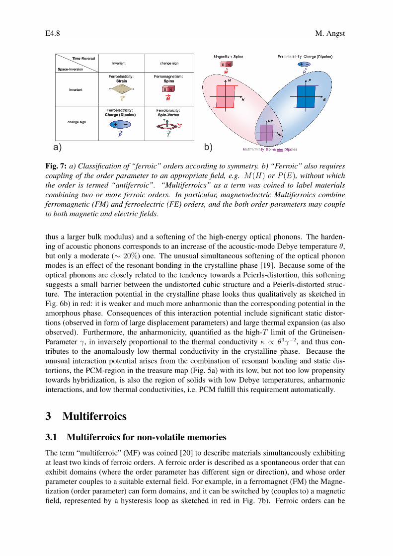
Fig. 7: a) Classification of “ferroic” orders according to symmetry. b) “Ferroic” also requirescoupling of the order parameter to an appropriate field, e.g. M(H) or P (E), without whichthe order is termed “antiferroic”. “Multiferroics” as a term was coined to label materialscombining two or more ferroic orders. In particular, magnetoelectric Multiferroics combineferromagnetic (FM) and ferroelectric (FE) orders, and the both order parameters may coupleto both magnetic and electric fields.
thus a larger bulk modulus) and a softening of the high-energy optical phonons. The harden-ing of acoustic phonons corresponds to an increase of the acoustic-mode Debye temperature θ,but only a moderate (∼ 20%) one. The unusual simultaneous softening of the optical phononmodes is an effect of the resonant bonding in the crystalline phase [19]. Because some of theoptical phonons are closely related to the tendency towards a Peierls-distortion, this softeningsuggests a small barrier between the undistorted cubic structure and a Peierls-distorted struc-ture. The interaction potential in the crystalline phase looks thus qualitatively as sketched inFig. 6b) in red: it is weaker and much more anharmonic than the corresponding potential in theamorphous phase. Consequences of this interaction potential include significant static distor-tions (observed in form of large displacement parameters) and large thermal expansion (as alsoobserved). Furthermore, the anharmonicity, quantified as the high-T limit of the Gruneisen-Parameter γ, in inversely proportional to the thermal conductivity κ ∝ θ3γ−2, and thus con-tributes to the anomalously low thermal conductivity in the crystalline phase. Because theunusual interaction potential arises from the combination of resonant bonding and static dis-tortions, the PCM-region in the treasure map (Fig. 5a) with its low, but not too low propensitytowards hybridization, is also the region of solids with low Debye temperatures, anharmonicinteractions, and low thermal conductivities, i.e. PCM fulfill this requirement automatically.
3 Multiferroics
3.1 Multiferroics for non-volatile memoriesThe term “multiferroic” (MF) was coined [20] to describe materials simultaneously exhibitingat least two kinds of ferroic orders. A ferroic order is described as a spontaneous order that canexhibit domains (where the order parameter has different sign or direction), and whose orderparameter couples to a suitable external field. For example, in a ferromagnet (FM) the Magne-tization (order parameter) can form domains, and it can be switched by (couples to) a magneticfield, represented by a hysteresis loop as sketched in red in Fig. 7b). Ferroic orders can be
IT materials E4.9
Fig. 8: Often the term “multifer-roic” is used in a wider sense toencompass simultaneously mag-netically and electrically orderedmaterials, e.g. antiferroelectricantiferromagnets. A magneto-electric coupling can exist withinthe even wider class of both mag-netically and electrically polariz-able materials.
classified according to the transformation-properties of the order parameter upon time-reversaland space-inversion (Fig. 7a). For example, ferroelastic order is invariant under both operations,whereas the order parameter of ferrotoroidicity (the alignment of toroidal moments arising froma ring-like arrangement of spins, see [21] and Fig. 7a) changes sign upon either operation. Aferroelectric (FE) that is also a ferromagnet (magnetoelectric MF) breaks both time-reversaland spatial-inversion symmetries, similar as a ferrotoroidic. The latter are also interesting formagnetoelectric applications, as they intrinsically exhibit a magnetoelectric effect. Research onferrotoroids is relatively new, and this fascinating topic cannot be covered in detail here, see[21] for a comprehensive review. Despite being relevant for applications, we also omit ferroe-lastics from further consideration, focusing entirely on magnetoelectrics from now on, writingjust multiferroic or MF for magnetoelectric multiferroic.The combination of FM and FE into a multiferroic is sketched in Fig. 7b). By definition then,such a material has a spontaneous magnetization that is switchable by a magnetic field and aspontaneous electric polarization that is switchable by an electric field. With a sufficient electro-magnetic coupling (which is not guaranteed), it is possible that the spontaneous magnetizationcan also be switched by an electric field, or the polarization by a magnetic field. However, multi-ferroicity does not imply that there is a magnetoelectric effect , and conversely magnetoelectriceffects can occur in the much wider class of materials that are simultaneously magneticallyand electrically polarizable (Fig. 8). In practice, magnetic and electric ordering tendencies willmake a strong magnetoelectric coupling much more likely, however, as indicated above. Sinceactual FM FE are more rare than antiferromagnetic (AFM) FE, most practitioners have come touse the term “multiferroic” in a wider sense, i.e. designating any magnetically ordered FE (oreven including anti-ferroelectric magnetic materials as well). We will follow this conventionthrough the rest of this section.As mentioned in Sec. 1, multiferroics may also be used for non-volatile memories. Consider theMRAM or magnetic random access memory, a non-volatile memory already in use. Schemati-cally, the already existing MRAM cells look similar to the device depicted in Fig. 9: Informationis encoded in the relative direction of the magnetization of two layers (parallel: 0, antiparallel:1), and it is read out with the giant magnetoresistance (GMR) effect, discovered in 1988 (P.Grunberg, Forschungszentrum Julich, and A. Fert, U Paris-Sud 11, Physics Nobel Price 2007).The main problem of the MRAM is the write operation requiring remagnetizing a layer withsignificant currents, making it slow and in particular highly power consumptive. If a layer ofan insulating material that converts a voltage to a magnetization could be attached, writing thedevice could occur with the simple and non-dissipative application of a voltage. The resulting
E4.10 M. Angst
Fig. 9: Concept of multiferroic memory cell [22]. As in the already existing magnetic RAM(MRAM), the information is encoded in the parallel or antiparallel alignment of the magetiza-tion of two layers, read out with the giant magneto-resistance effect. The addition of a layerof magnetoelectrically active (e.g. multiferroic) material allows to write the information byapplying a voltage, overcoming the main drawback of MRAM cells.
cell might be called “multiferroic” RAM or MF-RAM. The principal challenge in realizing theMF-RAM concept is to find a suitable material, for which a magnetoelectric coupling as de-scribed above occurs at room temperature and it is strong enough. Luckily, in order to switchthe magnetization it is not necessary to have a spontaneous magnetization in the magnetoelec-trically active (green in Fig. 9) layer. This is because of a directional magnetic coupling atthe interface between adjacent FM and AFM layers that is known as exchange bias (reviewedin [23]). Due to the directionality the magnetization direction in the ferromagnetic layer mayfollow the direction of the AFM order parameter in the AFM layer. Bi-stable switching of mag-netization by an electric field has indeed been demonstrated using exchange-bias and an AFMFE (see Sec. 3.5). However, although AFM instead of FE works, identifying suitable materialsis still a challenge.
3.2 Incompatibility between Ferroelectricity and Magnetism and waysaround
There are a lot of FM materials as well as a lot of FE ones. However, there are surprisinglyfew that are both, and understanding why is the first issue to be addressed [24]. One reasonfor the scarcity of multiferroics is simply symmetry: due to the need of breaking both time-reversal and spatial-inversion symmetries, out of the 122 magnetic point groups there are only13 that allow for both spontaneous magnetization and electric polarization to occur. Yet, manymaterials occur in one of these 13 point groups without being multiferroic. A simple reasonfor the rarity of multiferroics in the strict sense (FM FE) is that ferromagnets tend to be metalswhereas sustaining an electric polarization requires a material to be insulating. More interestingis to examine the wider class of magnetic FE, examples of which still turn out to be very rare.To address this latter question, we focus on perovskite-type ternary oxides ABO3 with A and Btransition metals, which contain both numerous (hundreds) FE and magnetic materials. At hightemperatures perovskites have an often slightly distorted, but centrosymmetric, cubic structure.The typical, and “traditional”, mechanism of ferroelectricity in these materials is an off-centerdisplacement of the B-site ion (for example Ti in BaTiO3), sketched in Fig. 10a). With a 4+valence from electron counting, Ti has an empty d shell. In fact, most FE perovskites have aB ion with empty d shell. Since magnetism requires unpaired d electrons, this automaticallyprevents multiferroicity in these cases.Since electrostatic interactions (Coulomb-repulsion between electron clouds on adjacent ions)
IT materials E4.11
3dxz
2px
O2- Ti4+
3dxz
2px
3dxz
2px
O2- Ti4+
a) b)
Fig. 10: “Traditional mechanism of ferroelectricity”: a) In perovskites ABO3 such as BaTiO3,an off-center displacement of the B ion leads to ferroelectricity. b) B-O Hybridisation energylevel scheme. If B has an empty d-shell, the shared electrons occupy exactly the bonding state(arrows). Additional electrons from the B d-shells would go into anti-bonding orbitals, loweringany energy gain from hybridisation.
Fig. 11: a) Oxygenlone pairs in a watermolecule. b) Bismuthlone pair in BiCrO3
[27]. The lone pair, iflocalized, breaks inver-sion symmetry and canlead to ferroelectricity.
favor the centrosymmetric arrangement of ions, the B ion displacement must be due to otherbonding considerations [24, 25]. Indeed, energy may be gained by formation of strong covalentbonds with one (or three) of the surrounding oxygen ions, with the energy gain from hybridiza-tion increased by decreasing the distance. Hybridization of the corresponding Op and and Bdorbitals leads to a bonding and an antibonding “molecular” orbital, as depicted in Fig. 10b). Ifthe d shell of the B ion is empty, the two electrons from the O2− ion (arrows) exactly fill thebonding orbital, maximizing the energy gain from hybridization. In contrast, any d electronsfrom B would have to go into the anti-bonding orbital, lowering the energy gained.While the above consideration makes plausible the strong preference for Bd0 configurations forthis “traditional mechanism of ferroelectricity”, I should remark that it is no absolute theoremand additional factors likely participate, but the detailed discussion we have to omit here [25].In any case, the connection between the “traditional mechanism of FE” in perovskites and the“d0th-ness” of the B ion is established empirically.The challenge, then, is to combine magnetism and FE despite the above-mentioned incompat-ibility. The conceptually simplest approach is to fabricate multi-phase materials or thin filmhetero-structures, using BaTiO3 or another traditional FE and a magnetic and magnetostrictivematerial such as CoFe2O4. Before briefly discussing this approach in subsection 3.5, we willfocus on single-phase multiferroics (in the wider sense of magnetically and electrically orderedmaterials). The focus here will be on the experimental side; for a review of different approachesfocusing on theory see [26].
E4.12 M. Angst
Fig. 12: a) BiMnO3 specific heat and low-field magnetization [30]. b) BiMnO3 dielectric con-stants in different magnetic fields [30]. c) BiMnO3 Polarization [31]. d/e) BiFeO3 thin film[32]/single crystal [33] polarization.
The straight-forward way to achieve both magnetism and FE in a single structure is for theformer to to originate from one subunit or ion, and the latter from another. For perovskites,one can for example on the B site partially substitute a ferroelectrically active (d0) ion with amagnetic ion. The general main problem with such an approach is that due to the different ions(or subunits) involved in magnetism and FE, the magnetoelectric coupling tends to be very lowin most cases [28].As a concrete example of the “independent subsystems” approach we consider FE due to lonepairs at the A site in perovskites with magnetic B ions [29]. Lone pairs are electrons not used inchemical bonds, occurring for example in water molecules as shown in Fig. 11a). Lone pairs arehighly polarizable, contributing e.g. to the polarizability of water. In perovskites, A site Bi3+
or Pb2+ have 6s electrons not participating in bonds and thus yielding lone pairs, see Fig. 11b).If these lone pairs are localized and ordered in one direction, inversion symmetry is brokenand an electric polarization results. In PbTiO3 this lone-pair mechanism helps the traditionalmechanism stabilizing the FE.In BiMnO3, the B site Mn3+ ions lead to FM below 100K (see Fig. 12a). The Bi lone pairsalone are sufficient to also stabilize FE (below 800K), as indicated by polarization hystere-sis loops (Fig. 12c). The occurrence of both ferroelectricity and ferromagnetism make thisan exceptional example of a real multiferroic in the strictest definition [34]. Despite of this,however, the magnetoelectric coupling is very weak, as indicated by an only very small (andalmost magnetic-field-independent) feature in the dielectric constant at the magnetic orderingtemperature (Fig. 12b) [30]. The smallness of the dielectric feature at the magnetic transition isconsistent with the expectation for an “independent subsystem” multiferroic.In BiFeO3 [35], the Fe spins order antiferromagnetically below 643K, in a complex spin struc-ture based on G-type antiferromagnetism (i.e. with each Fe ion surrounded by six antiparallelnearest neighbors) [36]. Bi lone pairs again lead to FE, below 1100K, with polarization hys-teresis loops both on thin films and more recently on high-quality single crystals (panels d,e)showing the intrinsic nature of a high (> 60µC/cm2, comparable with BaTiO3) polarization at
IT materials E4.13
room temperature [32, 33]. Room-temperature MF would make BiFeO3 a very good prospectfor applications if a significant magnetoelectric coupling were present as well. In analogy withBiMnO3, we would expect only very small coupling. However, sizeable coupling and controlof magnetism by electric fields has been demonstrated experimentally. The origin of this isconnected with a spiral part of the magnetic structure and corresponding couplings in the classof “spiral multiferroics”. I will therefore return to this issue later.There are many more examples of “independent subsystem” multiferroics, which typically haveFE transitions at much higher temperature than the magnetic transitions, and can have sizeableelectric polarization [28]. The main challenge in this group of materials is to achieve (andunderstand) a significant magnetoelectric coupling.
3.3 Ferroelectricity from Spin-SpiralsIn the next class of multiferroics to be considered [39, 40], the situation is reversed. Thesematerials have FE transitions at the same or, more typically, lower temperatures as the mag-netic transitions, typically show large magnetoelectric couplings as observed by magnetic-fieldeffects on dielectric constants and polarization, but conversely have much smaller electric po-larizations.The first [37], and possibly most, studied example of this class is TbMnO3, which also crys-tallizes in a perovskite-type structure (c.f. Fig. 10a), with Tb at the A and Mn at the B site(similar effects also occur when Tb is replaced by other rare earths, e.g. Dy or Gd). The Mnspins order around 40K, with an additional magnetic phase transition at 26K. Additionally, Tb4f moment order appears below 10K. The magnetic transitions are well visible in magnetiza-tion and specific heat data (Fig. 13a). An electric polarization in c direction appears at the 26Kmagnetic transition (Fig. 13b), already an indication of a “magnetically driven” FE. The valueof the polarization, 800µC/m2 = 0.08µC/cm2 is very small compared to traditional FE, withtypical values > 10µC/cm2, or also some of the MF discussed above.By the application of a magnetic field ∥b the direction of the polarization can be changed fromc to a (Fig. 13c/d), evidence of an enormous electromagnetic coupling [37]. The polarizationflop correlates with a meta-magnetic transition, and a detailed understanding of the magneticstructure in the different phases seems to be required to address this issue, as well as the generalorigin of the FE in TbMnO3 and related compounds. Neutron and resonant x-ray diffraction
Fig. 13: TbMnO3 a/b) T dependence of magnetization, specific heat, and electric polarization.c/d) c and a component of polarization in different magnetic fields applied ∥b. Panels a-d after[37]. e/f) Spin structure below 26K, with projection to bc plane [38].
E4.14 M. Angst
Fig. 14: a) Spiral (cycloidal) spin order arises as classical ground state of Heisenberg spinchain with nearest neighbor FM and next-nearest neighbor AFM coupling. b) Frustration ofIsing spins with AFM nearest-neighbor coupling on a triangle. c) Illustration of Dzyaloshinskii-Moriya interaction interaction (DMI) between two magnetic ions (see text). d) DMI can lead toweak ferromagnetism in antiferromagnets such as Fe2O3 or LaCu2O4. e) DMI can also lead toweak ferroelectricity in spiral magnets. Panels a and c-e after [39].
data indicate that the spins initially order in an incommensurate, but almost collinear (slightlycanted) amplitude-modulated structure [41, 42, 43]. The 26K transition corresponds to thetransformation into a spiral (cycloidal) spin structure, shown in Fig. 13e/f). The spins rotatearound the a axis, whereas the propagation is along b. This specific spin configuration seems tobe connected with a polarization along c.The absence of an electric polarization associated with the high T spin structure and both thepresence and the direction of the polarization in the low T cycloidal spin structure can be under-stood from symmetry-arguments on a phenomenological level [44]. While any spin orderingbreaks time-reversal symmetry, an electric polarization also needs broken inversion symme-try (Fig. 7a). The spin structure above 26K is inversion-symmetric, and therefore cannot giverise to any polarization. The cycloidal low T structure, on the other hand, is not inversion-symmetric (spatial inversion inverts the sense of direction of the rotation of the spins), allowingfor an electric polarization. This is formalized using a Ginzburg-Landau free energy densityapproach, which in the simplest case of cubic symmetry gives a polarization [44]
−→P (−→r ) = γχe
[(−→M(−→r ) · ∇
)−→M(−→r )−−→
M(−→r )(∇ · −→M(−→r )
)], (1)
where χe is the electric susceptibility. This symmetry argument shows that electric polarizationcan arise from spatially inhomogeneous non-centrosymmetric magnetism.The mechanism by which such magnetic structures arise is “frustration”, the existence of com-peting interactions. Consider for example a Heisenberg Spin chain (Fig. 14a): with only nearest-neighbor interaction J
−→S n ·
−→S n+1 the ground state is either a parallel (J < 0) or alternating
(J > 0) spin-arrangement, but if there is a FM nearest-neighbor coupling J < 0 and a suffi-ciently strong AFM next-nearest-neighbor coupling J ′ > −J/4 the ground-state is a cycloid,as realized in TbMnO3. Frustration and correspondingly complex spin configurations can alsoarise with only nearest-neighbor interactions, for example on triangular lattices with AFM cou-pling (Fig. 14b). Returning to the cycloid, it can be described by
−→S (−→r n) = S1
−→e 1cos(−→q · −→r n) + S2
−→e 2cos(−→q · −→r n), (2)
where the unit vectors −→e i, i = 1, 2, 3 form an orthonormal basis, −→e 3 being the direction aroundwhich the spins rotate, and −→q is the propagation vector. The cycloidal ground state has S1 = S2,
IT materials E4.15
−→q ⊥ −→e 3, and |−→q | = 2arccos(−J ′/4J). The spins Si provide the magnetization Mi, and theaverage polarization is then obtained with Eq. (1) as
⟨−→P ⟩ = V −1
∫ −→P (−→r )d3r = γχeM1M2[
−→e 3 ×−→q ]. (3)
Eq. (2) can describe also states other than a cycloidal. For example, for −→q ∥−→e 3 it describes aproper screw instead: it is clear from Eq. (3) that there is no uniform polarization in this case.Also, the pure sinusoidal amplitude modulation that due to magnetic anisotropies has to replacethe cycloidal ground state at sufficiently high T , as is the case in TbMnO3, is described by Eq.(2), by simply setting either S1 or S2 to 0. Again, there is no average polarization according toEq. (3) − consistent with the experiment. Finally, the “polarization” flop upon application of amagnetic field (Fig. 13c/d) is associated with a flop in the cycloidal spin-rotation axis, furtherconfirming the model [45].Intense research activity in the past few years has uncovered countless examples of materialswith FE associated with spin spirals [28]. These materials have very diverse crystal structures,but Eq. (3), despite being a simplification neglecting e.g. anisotropy effects, holds in most cases.However, this phenomenological description does not address the microscopic origin of spin-spiral-based FE and in particular can not provide any estimate of the magnitude of the polar-ization that may be expected. A plausible microscopic mechanism [46] that at least contributesto the spin-spiral FE is the ion displacement due to the antisymmetric Dzyaloshinskii-Moriya(DM) interaction [47], which is a relativistic correction to the usual superexchange J
−→S i ·
−→S j .
It is described by an energy term of the form
EDMij =
−→D ij ·
(−→S i ×
−→S j
), (4)
where−→D ij is a material-specific vector-coefficient. For superexchange between two neighbor-
ing magnetic ions via oxygen as depicted in Fig. 14c),−→D ij∥−→x ∝ −→r 12, further Dij is also
proportional to the spin-orbit coupling constant. As such, |−→D ij| is a measure of local inversion-
symmetry breaking, and the interaction absent when there is a center of inversion between thetwo magnetic ions. Discovered around 1960 [47], the DM interaction was first used to explainthe weak FM observed in some primarily AFM crystals of low symmetry, such as commonrust Fe2O3, or LaCu2O4. The situation in the latter material is sketched in Fig. 14d). Normalsymmetric superexchange leads to AFM order with alternating horizontal Cu spins. However,because the oxygen ions mediating the exchange are offset from the line connecting the Cu ions,the DM term (4) is also present. In this case,
−→D ij has alternating sign, and minimization of the
energy is obtained by a small canting of the spins with correspondingly alternating−→S i ×
−→S j ,
yielding a net magnetic moment perpendicular to the spin chain [39].For the spin-spiral, the reverse occurs (Fig. 14e). Here, the spin-canting is the starting point,and
−→S i ×
−→S j has the same sign for all pairs of neighboring magnetic sites. Correspondingly,
the energy can be lowered by creation of−→D ij by displacing the oxygen ions all in the same
direction perpendicular to the chain (−→q ) and the spin-rotation axis. Therefore, this “inverseDM” model predicts the same direction of the polarization as the phenomenological Eq. (3).It should be remarked that in addition to these ion displacement considerations there is also apurely electronic contribution [48]. However, comprehensive density functional calculationssuggest that the ionic contribution to the FE polarization is dominant, at least in TbMnO3 [49,50]. As a microscopic model, the strength of the coupling Dij and the resulting polarization can
E4.16 M. Angst
a) b)
Fig. 15: Room-temperaturemultiferroicity in theZ-type hexaferrite(Ba0.17Sr0.83)3Co2Fe24O41
induced by magnetic fieldsH . a) Electric polarizationP vs H at different T . b)Magnetization vs H . After[51].
be calculated. Unfortunately, the coupling strength is set by the spin-orbit coupling, which as arelativistic effect is intrinsically very small. Correspondingly, the small polarization measuredon TbMnO3 is not a coincidence, but rather polarizations reaching more than 1µC/cm2 cannotbe expected for spin-spiral based FE, values that may be too low for many applications.Another problem with respect to potential applications until recently was the very low tem-perature scale, e.g. 26K by TbMnO3 (Fig. 13a), rather typical for spin-spiral FE. The basicreason for this is that the frustration inherently needed for the creation of the spin spiral alsosuppresses the ordering temperature. However, in recent years, spin-spiral FE with tempera-ture scales reaching room temperature were discovered, most prominently the large family ofhexaferrites with several complex structure types. Here, proper-screw type magnetic structurestransform into transverse-conical spin structures upon application of a small magnetic field (see,e.g., [52]). In the hexaferrite Ba0.17Sr0.83)3Co2Fe24O41 MF at room temperature has been un-ambiguously demonstrated (see Fig. 15 [53, 51]) and further exploration of the family holdspromise of discovering compounds suitable for IT applications.
3.4 Collinear “magnetic ferroelectrics” and ferroelectricity from chargeorder
As the electric polarization of the spin-spiral FE is intrinsically limited by the weak spin-orbitcoupling, the question arises whether there are any other mechanisms through which FE can begenerated by magnetism. This is indeed the case, and I will describe here one mechanism and acorresponding example compound. Consider a chain of alternating ions (Fig. 16b). These maybe different elements, or alternatively ions of one element in different valence states. The ionsshould be all magnetic with magnetic anisotropy providing an Ising-chain. If we have com-peting interactions as in Fig. 14a), but Ising instead of Heisenberg spins (i.e. we have uniaxialmagnetic anisotropy), the ground state (for J ′ > −J/2) is an ↑↑↓↓ configuration as indicatedin Fig. 16b). As the magnetic exchange between neighboring ions depends on the distance be-tween them, there is in the reverse also an exchange striction, which will tend to decrease thedistance between neighboring ions with parallel spin-alignment. The result is pairs of ions cor-responding to electric dipoles (c.f. Fig. 16b). It is remarkable that both the alternating-ion chainwithout the spins and the spin-chain ignoring the difference between the two ions are centro-symmetric. Inversion-symmetry is only broken, and FE allowed, by their combination. Becausethis mechanism does not depend on relativistic effects, much larger electric polarizations thanin the spin-spiral FE might be expected [54].A rather clear example of the above mechanism is provided by Ca3CoMnO6 [55], whose crystalstructure provides for chains of alternating Co and Mn, and where Ising-magnetism with ↑↑↓↓
IT materials E4.17
Fig. 16: Ca3CoMnO6
[55]. a) Crystal struc-ture b) Co/Mn Isingchains with two statesof ↑↑↓↓ spin order-ing. Ions are dis-placed from ideal posi-tions (broken circles) bymagnetostriction, lead-ing to an electric polar-ization. c) Polarizationfrom pyroelectric cur-rent measurements.
spin arrangement along these chains occurs (Fig. 16a/b). As shown in Fig. 16c), pyroelectriccurrent measurements indeed indicate a spontaneous electric polarization below the onset ofmagnetic order [55]. Unfortunately and contrary to the expectation, the observed polarizationis even lower than in TbMnO3. Likely, this exchange-striction mechanism is also the princi-pal driving force for FE in the double-layer manganites, where however different Mn valencestates provide for one of the necessary preconditions [54]. In those compounds also only smallpolarizations are observed.Apart from the spin degree of freedom there are two other electronic degrees of freedom, chargeand orbital. Ordering of one of these degrees of freedom may result in FE as well [54]. Inparticular, one can expect to obtain an electric polarization from any charge ordering (CO), thelocalization of charge carriers on parts of the ions in a spatially periodic fashion, that breaks spa-tial inversion symmetry. Although MF then is not quite as inherent as in the case of spin-basedFE, the fact that the electrons that are involved in charge or orbital order inevitably also haveuncompensated spins provides for a high probability of multiferroicity to result. Furthermore,because the same electrons are involved in the different orderings, a significant coupling can beexpected as well. The main advantage of FE from CO, compared to “magnetic ferroelectricity”,is that much higher electric polarizations can be expected.The difficulty in obtaining FE from CO is that the Coulomb-interaction driving the CO tendsto avoid non-centrosymmetric configurations. An example of how a non-centrosymmetric andthus ferroelectric CO could be obtained is given by considering charge order on a chain [54]. Ifthere is one electron per two sites, the expectation is to obtain a chain with ions of alternatingvalence states. However, apart from this situation, termed “site-centered” charge order, it isalso possible that the electrons localize on the bonds between the ions in a “bond-centered”charge order, a situation realized by a Peierls-distortion well-known in low-dimensional (mainlyorganic) compounds. Here, the ions remain equivalent, but not the bonds between them, and,as a result, there is a tendency to dimerization. Neither “site-centered” nor “bond-centered”charge order breaks inversion-symmetry by itself, but their combination does [56, 54]. Thesituation and resulting electric dipoles is the same as in Fig. 16b), except that the ion shiftsare due to “bond-centered” charge order rather than magnetostriction (and the coloring is dueto “site-centered” charge order). Such a mechanism was proposed to be active [56] in Ca-doped PrMnO3 for certain intermediate Ca doping, but direct experimental confirmation of thisscenario has not been obtained, not least due to a too large conductivity of (Pr,Ca)MnO3.
E4.18 M. Angst
a)
d)b) c)
Fig. 17: Ferroelectric charge order CO in LuFe2O4? a) CO reflections by high-energy x-raydiffraction. b) Model, proposed in 2005 [57], of the Fe2+/3+ CO in Fe/O bilayers, the basicstructural subunit. Different average valence of the two layers makes the bilayer polar, indi-cated by the arrow. c) Pyroelectric current measurements [57] indicated a large ferroelectricpolarization. d) Recently revised model of the CO, based on the first structure refinements [58]:The bilayers are charged rather than polar, excluding ferroelectricity due to CO.
Unambiguous confirmation of FE due to CO is elusive also in other compounds so far, andthere are as yet only few examples, none of them absolutely clear. We first discuss an examplethat scattering methods recently showed is rather a non-example: The material most often citedas the prototypical example of CO-based FE (see, e.g., [28]) is LuFe2O4, which has a layeredcrystal structure with Fe/O bilayers as the the electronically active subunit. The Fe ions havean average valence of 2.5+, so a Fe2+/Fe3+ charge ordering can be expected. Superstructurereflections that can be attributed to charge order do indeed appear slightly above room tempera-ture (Fig. 17a). The location of these reflections at “(h, h) = (1
3, 13)” and equivalent is consistent
with the charge configuration within a bilayer indicated in Fig. 17b), first proposed by Ikeda andcoworkers in 2005 [57]. Because one of the two layers is rich in Fe2+ and the other in Fe3+
(as indicated by a shading of the layers), the bilayer would become polar by such a CO. Inaccordance with this polar CO model, pyroelectric current measurements (Fig. 17c) suggesteda spontaneous polarization, also up to slightly above room temperature [57]. Although thesepolar bilayers were generally accepted in the extensive literature on LuFe2O4, a direct proof foror against was lacking. Only very recently, the charge-ordered crystal structure could be refinedbased on single-crystal x-ray diffraction data measured on an almost-mono-domain crystal. TheFe2+/Fe3+ arrangement deduced from the refinement, which is supported also by x-ray mag-netic circular dichroism and neutron diffraction, contains bilayers that are charged rather thanpolar (Fig. 17d), excluding CO-based FE in LuFe2O4 [58].
A remarkable, if verified, example of CO-driven FE would be classical magnetite Fe3O4, theoldest magnetic material known to mankind and also the classical (1939) example of a CO tran-sition. Despite decades of research, the very complex CO structure of magnetite has eluded adetermination until recently, when Senn and coworkers achieved a refinement based on high-energy x-ray diffraction on a tiny (40µm) almost-mono-domain crystal [59]. The refined struc-ture, consistent with density-functional calculations [60] is indeed polar, which leaves only toshow that it can actually be switched by an electric field. The latter is complicated by residualconductivity and associated “relaxor-like characteristics”, indicated by dielectric spectroscopy[61].
IT materials E4.19
Fig. 18: Electric-Field control ofmagnetic state inTbMnO3 [38]. a)Polarized neu-tron scatteringdependence onPolarization, se-lected by voltagebias on cooling. b)correspondence ofspin-spiral helicityand polarization.
3.5 Electric-field control of magnetism and multiferroic heterostructures
Indications for magnetoelectric coupling have been observed for many MF within the different“classes” described above. For the spin-spiral FE in particular, control of the electric polariza-tion by a magnetic field has been shown in a dramatic way already in the first paper [37] (Fig.13c/d). Given the mechanism by which the polarization arises directly from the spin structure,this is hardly surprising. However, for many applications such as the MF-RAM (Fig. 9) it ismore important to control the magnetization by an electric field. Demonstrations of magneto-electric coupling in this direction are much more rare. Still, the DM interaction as an energycontribution Eqn. (4) works both ways, as we have seen also from the example of weak FM.In the spin-spiral FE there is generally no spontaneous magnetization that can be switched, buton the other hand reversing the sense of rotation along the spiral reverses the associated FEpolarization (Fig. 18b), therefore switching the polarization by an applied electric field shouldbe able to revert the sense of rotation of the spins. The technique most suited to measure thesense of rotation is polarized neutron scattering, because the intensity of magnetic reflectionswill be different for the neutron spins parallel or antiparallel to the chirality of the spin-spiral.Measurements on TbMnO3 (Fig. 18a) indeed showed different sense of rotations of the spinsafter cooling to the FE phase in a positive or negative electric field [38].Whereas strong magnetoelectric coupling is inherent in the spin-spiral FE, this is not the casefor MF in general, as we have seen on the example of BiMnO3. Surprisingly, electric-field con-trol of magnetism is possible in BiFeO3 [62], despite of this material being in the same “class”of MF as BiMnO3. To understand why, we need to consider the magnetic structure [36]: it isbased on a G-type AFM, where each Fe site spin has six antiparallel nearest neighbors, but over-laid on this are a spin-canting and long-period cycloidal modulation (Fig. 19b). The cycloidalmodulation in this case does not arise from magnetic frustration, but rather is a consequenceof the DM interaction (4). Indeed, it was long known that apart from creating weak FM, theDM interaction can also lead to cycloidal spin configurations. The mechanism is exactly asdiscussed above and sketched in Fig. 14e), except that the off-centering of the oxygen ions isthe origin rather than the effect. In BiFeO3, this off-centering is due to the electric polarization,which in turn is driven by the “lone-pair” mechanism. This compound is therefore the oppositeto TbMnO3: rather than FE due to spin-spiral, we have spin-spiral due to FE. Different direc-
E4.20 M. Angst
Fig. 19: Electric-Field control of magnetic state in BiFeO3. a) sketch of spiral domains andrelation-ship with polarization [62]. Domains can be selected by external electric field. b) inone domain, spin structure is given by superposition of G-type antiferromagnetic order, spincanting, and long-period spiral [62]. c) XMCD-PEEM images [63] showing magnetic contrastof a CoFe-layer, whose magnetization is switched using exchange-bias to an adjacent BiFeO3
layer, the magnetism of which is controlled by an electric field. Images left to right are obtainedby two consecutive electrical field switches.
tions of the polarization will correspond to different possible directions (domains) of the spinspiral (Fig. 19a), providing a mechanism for switching of magnetic domains by an electric field,as demonstrated by Lebeugle and coworkers [62].Because all this works even at room temperature, BiFeO3 appears to be a most promising can-didate for building MF-RAM cells (Fig. 9) and similar applications. What is needed next is amechanism, such as exchange bias (see lecture E5), through which the magnetic domain config-uration of BiFeO3 is linked to the ferromagnetic domain structure of an adjacent soft FM. Thiswas successfully demonstrated by Chu and co-workers [63], who built a heterostructure withBiFeO3 and CoFe as the soft FM (see also [64]. In Fig. 19c) three XMCD-PEEM images ofthis device, with a small CoFe island in the center, are shown. The contrast is given by differentmagnetic polarities. Between neighboring images, an electric field is applied, first in one, thenin the other direction. The clearly visible switching of the CoFe magnetization by the electricfield was achieved at room temperature.In multiferroic devices such as the MF-RAM (Fig. 9) the materials occur not in the bulk form,but in (patterned) heterostructures. In this case interface effects can be of crucial importance. Agood example is the use of the exchange-bias effect between a FM and an AFM FE, e.g. for aCoFe-BiFeO3 heterostructure as discussed just above (c.f. Fig. 19c). But with interface effectsit is even possible to create composite multiferroics out of materials that are all non-multiferroicintrinsically. One approach (for reviews see, e.g., [65, 66]) uses strain at the interface to couplea FE material (via the piezoelectric effect) to a FM material (via magnetostriction). This worksbest with FE with large piezoelectric coefficents (in particular Pb(Zr,Ti)O3 or PZT) and FM withlarge magnetostriction. In such systems, magnetoelectric coupling coefficients more than twoorders of magnitude larger than in single-phase MF have been observed. However, while theconcept of strain-coupling is simple, the detailed modeling is difficult, and so is experimentalreproducibility, given strong influence of defects, domains etc.A more recent approach uses the strong sensitivity of correlated oxides to charge carrier density,employing FE gate oxides. The two polarization states of the gate, tunable by low voltages, thencorrespond to two different effective doping levels in the magnetically active correlated oxide.
IT materials E4.21
Fig. 20: Magnetoelectric hysteresis-loop showing the magnetic response(Kerr-rotation ∝ M ) as a functionof applied electric field at 100K of aPZT(250 nm)-La0.8Sr0.2MnO3(4 nm) het-erostructure grown on a SrTiO3(001) sub-strate. Insets represent the magnetic andelectric states of the two layers. After [67].
For the latter, doped perovskite manganites, such as La1−xSrxMnO3, which are characterizedby competing phases and an intricate interplay of magnetism, structure, and electron transport[68], can be employed. For an appropriate composition, the additional effective doping by thegate can trigger a transition to a phase with different magnetic properties. Following this recipe,Molegraaf and coworkers [67] have recently demonstrated a large magnetoelectric coupling ina PZT-La0.8Sr0.2MnO3 bilayer heterostructure (Fig. 20). The effect shown is much larger thanin single-phase multiferroics and approaches values of strain-coupled multiferroic heterostruc-tures, while being of purely electronic origin [69]. Similarly, an electronic reconstruction atthe interface between a FM and a FE can induce a purely magnetoelectric coupling, as recentlydemonstrated for BaTiO3 and Fe or Co [70].For the realization of an MF-RAM (Fig. 9) and further spintronic applications it is also neces-sary to consider the transport properties of multiferroic heterostructures, i.e. multiferroic tunnel-junctions. Such a tunnel junction depending both on electric and magnetic states for a total offour memory states has already been demonstrated [71]. There is currently much research beingconducted in this field closest to application, and promising results can be expected.
4 Concluding remarks
On the way towards non-volatile memory applications actually on the market, phase change ma-terials are further advanced than multiferroics. In fact, a 512 Mbit PC-RAM is already used asa replacement of slower flash in some mobile phones [72]. However, the relatively low storagecapacity compared to the currently available 64 Gbit flash-based USB sticks suggests scala-bility problems and additionally the high operating current densities force device architecturesthat put the PC-RAM to a severe cost-disadvantage compared to Flash. These problems willhave to be overcome if PC-RAM is to become more than a niche product. Aiming towards anuniversal memory (Sec. 1), new routes need to be pursued in research. One such route, goingfrom single phases to heterostructures, is starting to be pursued, with promising results [73]:in a multilayer (GeTe)2-(Sb2Te3)4 system, switching currents considerably lower and lifetimesorders of magnitude higher than for Ge2Sb2Te5 have been observed.For multiferroics, on the other hand, the room-temperature switchability of a magnetic layer,crucial for the MF-RAM, has been shown using BiFeO3 [63, 64], and also on heterostructuressuch as Pb(Zr,Ti)O3-La0.8Sr0.2MnO3 [67], though the issue of the (presumably fast) time scalesof the switching have to be addressed experimentally. However, so far a fully functioningMF memory cell has yet to be demonstrated, and from there to an integrated circuit it is stilla way to go. All this suggests that it will still be some time before we can expect to buydevices that use MF-RAM. A large contrast to the PCM with their rather common mechanism
E4.22 M. Angst
and clear location on a “treasure map” (Fig. 5a) is that there are many potential ways towardsmultiferroicity. Currently rather classical BiFeO3 with its lone-pair ferroelectricity seems tohave the lead, but good progress is also being made recently with spin-spiral based ferroelectricssuch as hexaferrites, and artificial heterostructures show promise as well. This richness ofmaterials, effects, and mechanisms in multiferroics provides for some unpredictability, but alsofor chances in the medium and long term. Of course, in the long term, some of the various moreexotic concepts mentioned in Sec. 1, that could not be covered in detail, might prevail.In any case, research on a materials or heterostructure level, will continue for both PCM andmultiferroics to contribute critically to the eventual realization of integrated devices. I hopethat this lecture also showed how the application of a large variety of scattering methods iscrucial to make progress in understanding these PCM and multiferroics. Although the scatteringexamples shown are all from bulk systems, I would like to stress that scattering methods are alsoindispensable for the detailed understanding of heterostructures, the last step short of a device.
AcknowledgmentI gratefully acknowledge R. P. Hermann for contributing graphics used in Sec. 2, and A. Weberfor proof-reading of the lecture notes.
IT materials E4.23
References[1] D. Loss and D. P. DiVincenzo, Phys. Rev. A 57, 120 (1998).
[2] L. DiCarlo et al., Nature 460, 240 (2009).
[3] F. Schwierz, Nat. Nanotech. 5, 487 (2010).
[4] R. Waser, R. Dittmann, G. Staikov, and K. Szot, Adv. Mater. 21, 2632 (2009).
[5] L. Bogani and W. Wernsdorfer, Nat. Mater. 7, 179 (2008).
[6] P. Fromherz, A. Offenhausser, T. Vetter, and J. Weis, Science 252, 1290 (1991).
[7] M. Wuttig and N. Yamada, Nat. Mater. 6, 824 (2007).
[8] I. Friedrich, V. Weidenhof, S. Lenk, and M. Wuttig, Thin Solid Films 389, 239 (2001).
[9] W. Welnic and M. Wuttig, Materials Today 11, 20 (2008).
[10] N. Yamada et al., J. Appl. Phys. 69, 2849 (1991).
[11] G. Atwood, Science 321, 210 (2008).
[12] S. R. Ovshinsky, Phys. Rev. Lett. 21, 1450 (1968).
[13] C. Kim et al., Appl. Phys. Lett. 94, 193504 (2009).
[14] K. Shportko et al., Nat. Mater. 7, 653 (2008).
[15] L. Pauling, Nature of Chemical Bond (Cornell Univ. Press, New York, 1939).
[16] D. Lencer et al., Nat. Mater. 7, 972 (2008).
[17] S. Kohara et al., Appl. Phys. Lett. 89, 201910 (2006).
[18] J. Hegedus and S. R. Elliott, Nat. Mater. 7, 399 (2008).
[19] T. Matsunaga et al., Adv. Funct. Mat. 21, 2232 (2011).
[20] H. Schmid, Ferroelectrics 162, 317 (1994).
[21] N. A. Spaldin, M. Fiebig, and M. Mostovoy, J. Phys.: Condens. Matter 20, 434203 (2008).
[22] M. Bibes and A. Barthelemy, Nat. Mater. 7, 425 (2008).
[23] J. Nogues and I. K. Schuller, J. Magn.Magn. Mater. 192, 203 (1999).
[24] N. A. Hill, J. Phys. Chem. B 104, 6694 (2000).
[25] D. I. Khomskii, J. Magn. Magn. Mater. 306, 1 (2006).
[26] S. Piccozzi and C. Ederer, J. Phys.: Condens. Matter 21, 303201 (2009).
[27] D. I. Khomskii, Physics 2, 20 (2009).
E4.24 M. Angst
[28] K. F. Wang, J.-M. Liu, and Z. F. Ren, Adv. Physics 58, 321 (2009).
[29] R. Seshadri and N. A. Hill, Chem. Mater. 13, 2892 (2001).
[30] T. Kimura et al., Phys. Rev. B 67, 180401(R) (2003).
[31] J. Y. Son and Y.-H. Shin, Appl. Phys. Lett. 93, 062902 (2008).
[32] J. Wang et al., Science 299, 1719 (2003).
[33] D. Lebeugle, D. Colson, A. Forget, and M. Viret, Appl. Phys. Lett. 91, 022907 (2007).
[34] Note that ferroelectricity in ideal stoichiometric BiMnO3 has recently become a very con-troversial issue, with antiferroelectricity as an alternative. For a summary of different evi-dences see I. V. Solovyev and Z. V. Pchelkina, New J. Phys. 10, 073021 (2008).
[35] G. Catalan and J. F. Scott, Adv. Mater. 21, 2463 (2009).
[36] I. Sosnowska, T. Peterlin-Neumaier, and E. Steichle, J. Phys. C:Solid State Phys. 15, 4835(1982).
[37] T. Kimura et al., Nature 426, 55 (2003).
[38] Y. Yamasaki et al., Phys. Rev. Lett. 98, 147204 (2007).
[39] S.-W. Cheong and M. Mostovoy, Nat. Mater. 6, 13 (2007).
[40] Y. Tokura and S. Seki, Adv. Mater. 21, 1 (2009).
[41] M. Kenzelmann et al., Phys. Rev. Lett. 95, 087206 (2005).
[42] J. Voigt et al., Phys. Rev. B 76, 104431 (2007).
[43] S. B. Wilkins et al., Phys. Rev. Lett. 103, 207602 (2009).
[44] M. Mostovoy, Phys. Rev. Lett. 96, 067601 (2006).
[45] N. Aliouane et al., Phys. Rev. Lett. 102, 207205 (2009).
[46] I. A. Sergienko and E. Dagotto, Phys. Rev. B 73, 094434 (2006).
[47] I. Dzyaloshinsky, J. Phys. Chem. Solids bf 4, 241 (1958); T. Moriya, Phys. Rev. 120, 91(1960).
[48] H. Katsura, N. Nagaosa, and A. Balatsky, Phys. Rev. Lett. 95, 057205 (2005).
[49] H. J. Xiang, S.-H. Wei, M.-H. Whangbo, and J. L. D. Silva, Phys. Rev. Lett. 101, 037209(2008).
[50] A. Malashevich and D. Vanderbilt, Phys. Rev. Lett. 101, 037210 (2008).
[51] S. H. Chun et al., arXiv:1111.4525.
[52] M. Soda et al., Phys. Rev. L 106, 087201 (2011).
IT materials E4.25
[53] Y. Kitagawa et al., Nat. Mat 9, 797 (2010).
[54] J. van den Brink and D. I. Khomskii, J. Phys.: Condens. Matter 20, 434217 (2008).
[55] Y. J. Choi et al., Phys. Rev. Lett. 100, 047601 (2008).
[56] D. V. Efremov, J. Van den Brink, and D. I. Khomskii, Nat. Mater. 3, 853 (2004).
[57] N. Ikeda et al., Nature 436, 1136 (2005).
[58] J de Groot et al., arXiv:1112.0978v1.
[59] M. S. Senn, J. P. Wright, and J. P. Attfield, Nature 481, 173 (2012).
[60] K. Yamauchi, T. Tetsuya, and S. Piccozzi, Phys. Rev. B 79, 212404 (2009).
[61] F. Schrettle et al., Phys. Rev. B 83, 195109 (2011).
[62] D. Lebeugle et al., Phys. Rev. Lett. 100, 227602 (2008).
[63] Y.-H. Chu et al., Nat. Mater. 7, 478 (2008).
[64] J. T. Heron et al., Phys. Rev. Lett. 107, 217202 (2011).
[65] R. Ramesh and N. A. Spaldin, Nat. Mater. 6, 21 (2007).
[66] C. A. F. Vaz, J. Hoffman, C. H. Ahn, and R. Ramesh, Adv. Mat 22, 2900 (2010).
[67] H. J. A. Molegraaf et al., Adv. Mater 21, 3470 (2009).
[68] A. P. Ramirez, J. Phys.: Condens. Matter 9, 8171 (1997).
[69] C. A. F. Vaz et al., Phys. Rev. Le 104, 127202 (2010).
[70] S. Valencia et al., Nat. Mater. 10, 753 (2011).