50
Material Technology and Testing (MNF 222) CHAPTER 8 Non Destructive Testing 1 Material Technology and Testing Dr. Gamal Abdou

Material Technology and Testing
(MNF 222)
CHAPTER 8
Non Destructive Testing
1Material Technology and Testing Dr. Gamal Abdou
Non Destructive Testing
Nondestructive testing (NDT) has been
defined as comprising those test methods
used to examine an object, material or
system without impairing its future
usefulness. The term is generally applied
to nonmedical investigations of material
integrity .
Objectives of NDT(1) to ensure product integrity, and in turn, reliability;
• To detect internal or surface flaws• To measure the dimensions of materials• To determine the materials’ structure• To evaluate the physical and mechanical properties of
materials
(2) to avoid failures, prevent accidents and save human life;
(3) to make a profit for the user;
(4) to ensure customer satisfaction and maintain the manufacturer's reputation;
(5) to aid in better product design;
(6) to control manufacturing processes;
(7) to lower manufacturing costs;
(8) to maintain uniform quality level;
(9) to ensure operational readiness.
Characteristics of NDT
• Applied directly to the
product
• Tested parts are not
damaged
• Various tests can be
performed on the
same product
• Specimen preparation
not required
• Can be performed on
parts that are in
service
• Low time
consumption
• Low labour cost
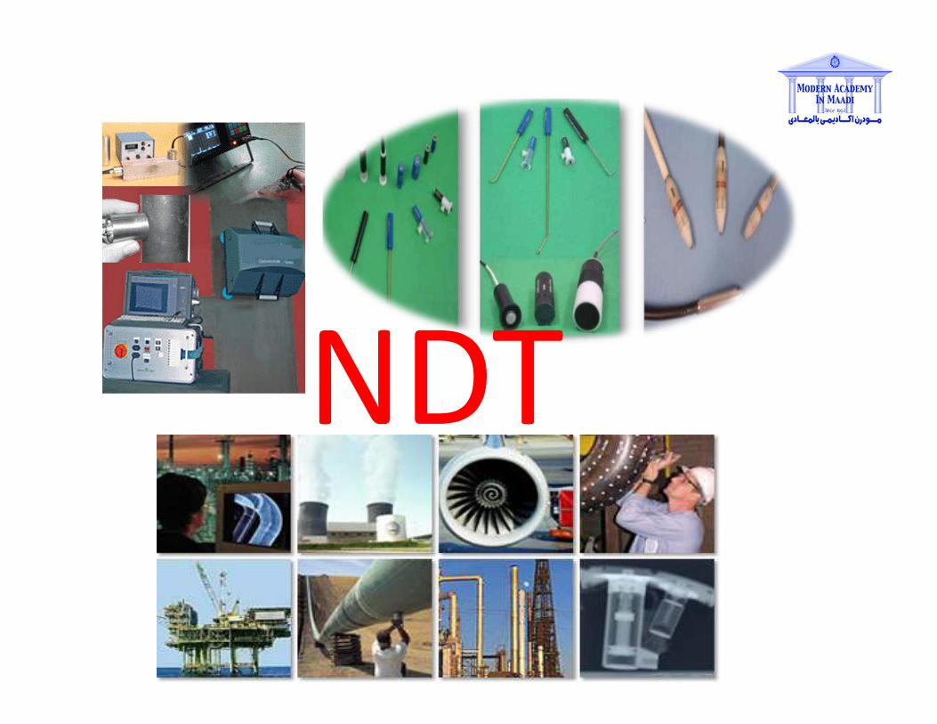
NDT
NDT Methods1. Visual Inspection
2. Liquid penetrant method
3. Ultrasonic Inspection
4. Radiography methods• X-ray radiography & fluoroscopy
• γ- ray radiography
5. Eddy current testing
6. Magnetic particle testing
7. Thermography
ADVANTAGES OF NDT
•The equipments are easy to handle
•Defects can be detected without damaging the components
•Methods are quick and accurate
•Components can be sorted out on the basis of electrical, magnetic or chemical properties
•Test results and other information can be conveniently recorded on paper films, cassettes and floppies

DIFFERENCE BETWEEN DESTRUCTIVE AND
NON DESTRUCTIVE TEST
NON DESTRUCTIVE TEST DESTRUCTIVE TEST
Used for finding out defects of
materials
Used for finding out the properties
of the material
Load is not applied on the material Load is applied on the material
No load applications, so no chance
for material damage
Due to load application, material
gets damaged
No requirement of special
equipments
Special equipments are required
Non expensive Expensive
Less skill Skill is required
e.g: dye penetrate test, ultrasonic,
radiography, etc
e.g: tensile test, compression test,
hardness test, etc
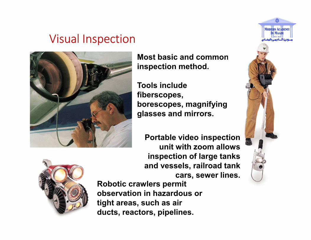
Most basic and common
inspection method.
Tools include
fiberscopes,
borescopes, magnifying
glasses and mirrors.
Robotic crawlers permit
observation in hazardous or
tight areas, such as air
ducts, reactors, pipelines.
Portable video inspection
unit with zoom allows
inspection of large tanks
and vessels, railroad tank
cars, sewer lines.
Visual Inspection
Dye Penetrant Inspection
Surface breaking defects only detected
Penetrant applied to the component and drawn into
the defects by capillary action
Applicable to all non- porous and non absorbing
materials.
Penetrants are available in many different types
Water washable contrast
Solvent removable contrast
Water washable fluorescent
Solvent removable fluorescent
Post-emulsifiable fluorescent

Dye Penetrant Inspection

Dye Penetrant Inspection
Step 1. Pre-Cleaning
Cleaning preparation is very important on this method.
Usually solvent removal is been used

Dye Penetrant Inspection
Step 2. Apply penetrant
After the application of the penetrant the penetrant is normally
left on the components surface for approximately 15 minutes
(dwell time). The penetrant enters any defects that may be
present by capillary action
Dye Penetrant Inspection
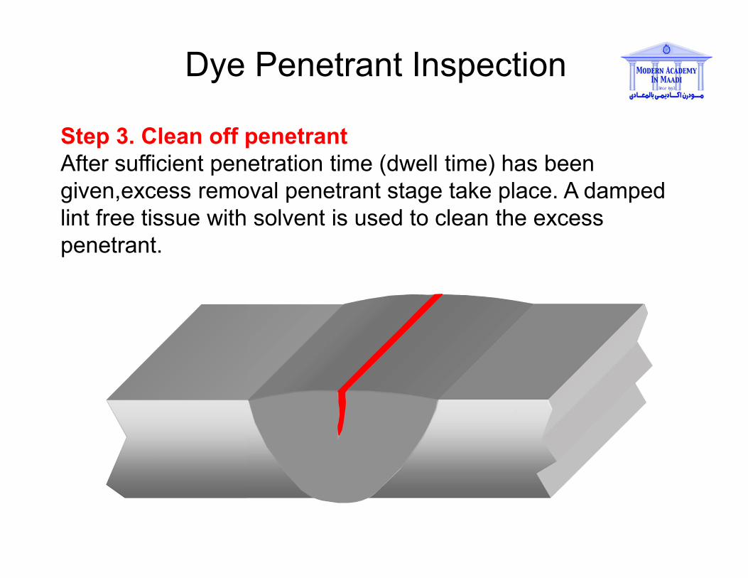
Step 3. Clean off penetrant
After sufficient penetration time (dwell time) has been
given,excess removal penetrant stage take place. A damped
lint free tissue with solvent is used to clean the excess
penetrant.
Dye Penetrant Inspection
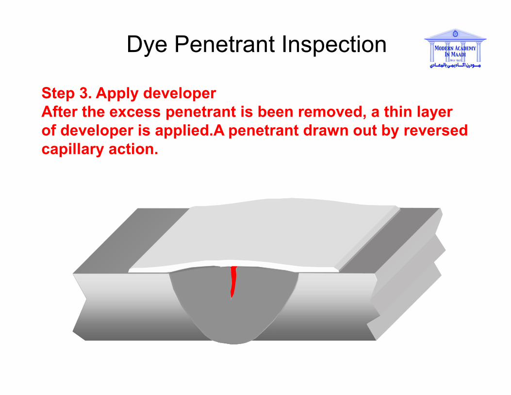
Step 3. Apply developer
After the excess penetrant is been removed, a thin layer
of developer is applied.A penetrant drawn out by reversed
capillary action.
Dye Penetrant Inspection
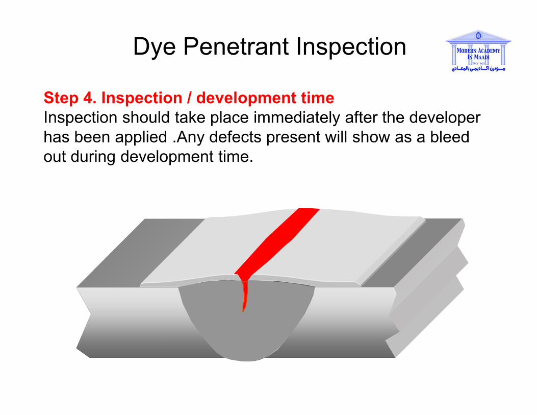
Step 4. Inspection / development time
Inspection should take place immediately after the developer
has been applied .Any defects present will show as a bleed
out during development time.
Dye Penetrant Inspection
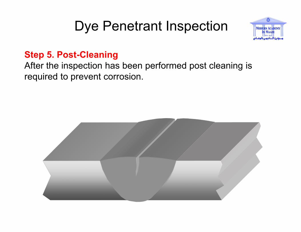
Step 5. Post-Cleaning
After the inspection has been performed post cleaning is
required to prevent corrosion.

Dye Penetrant Inspection
Colour contrast Penetrant
Fluorescent PenetrantBleed out viewed
under a UV-A light
source
Bleed out viewed
under white light
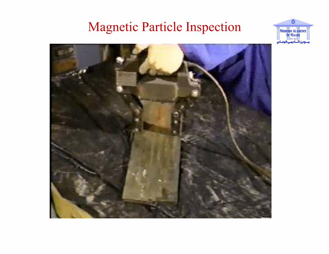
Magnetic Particle Inspection
Magnetic Particle Inspection
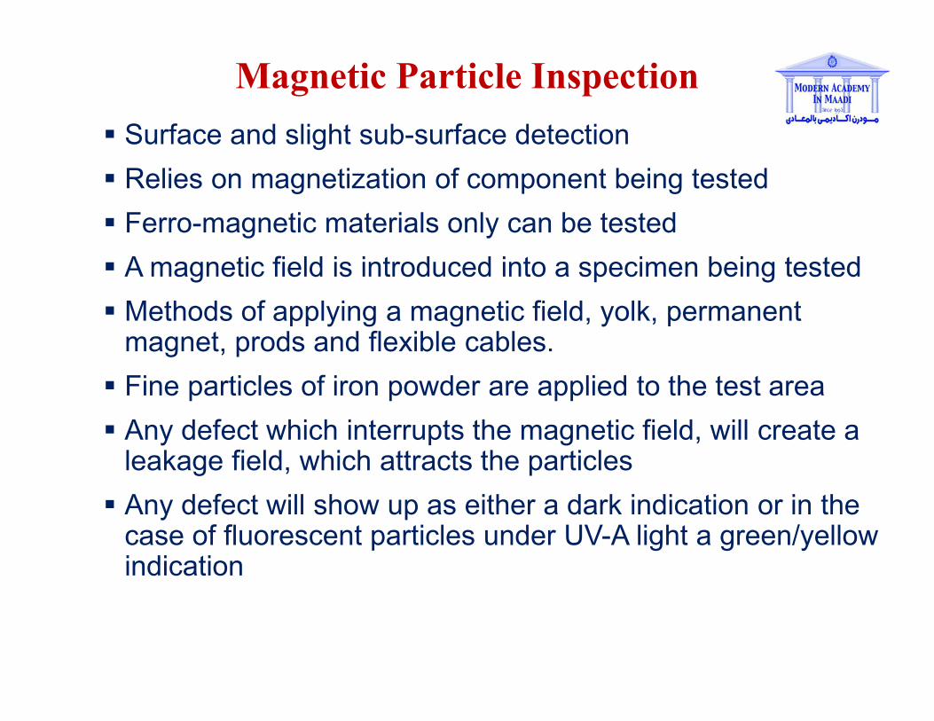
Surface and slight sub-surface detection
Relies on magnetization of component being tested
Ferro-magnetic materials only can be tested
A magnetic field is introduced into a specimen being tested
Methods of applying a magnetic field, yolk, permanent magnet, prods and flexible cables.
Fine particles of iron powder are applied to the test area
Any defect which interrupts the magnetic field, will create a leakage field, which attracts the particles
Any defect will show up as either a dark indication or in the case of fluorescent particles under UV-A light a green/yellow indication
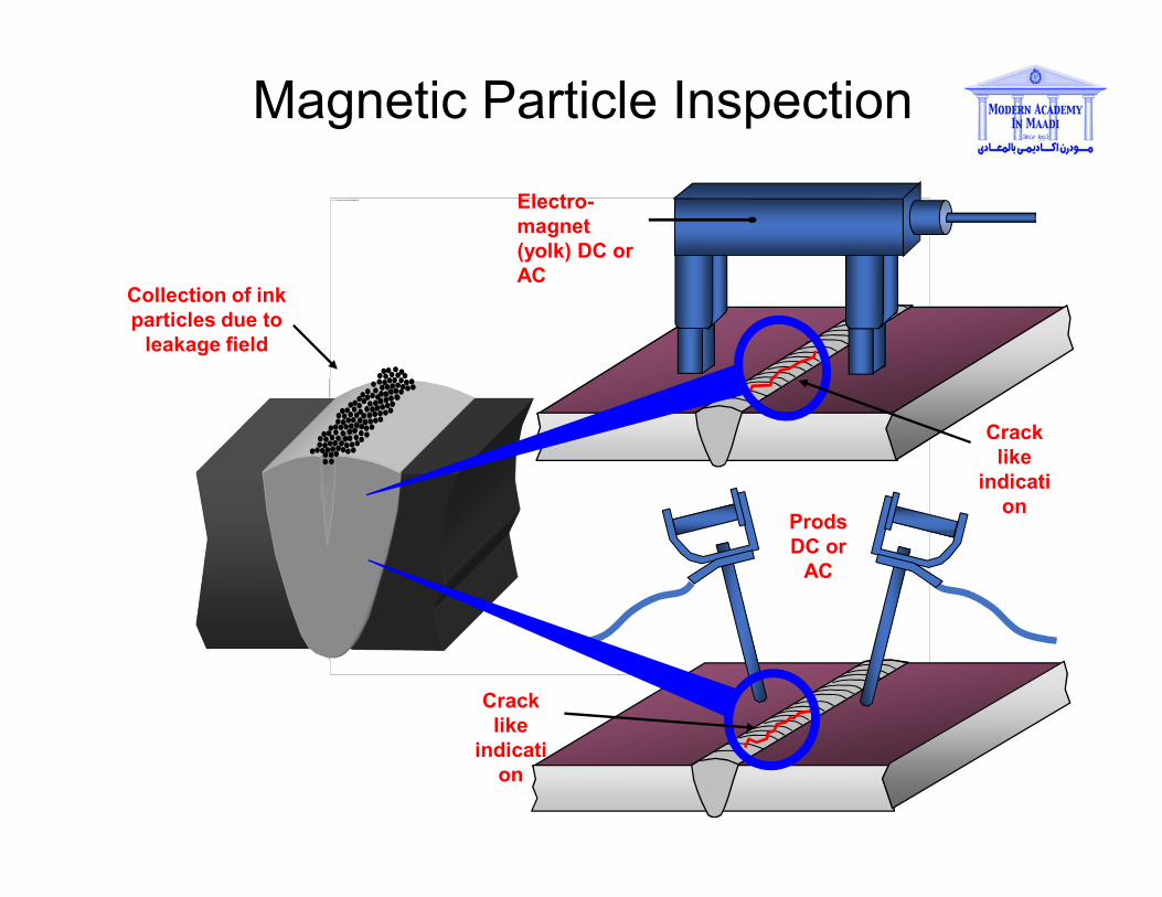
Collection of ink
particles due to
leakage field
Magnetic Particle Inspection
The picture can't be displayed.
Prods
DC or
AC
Electro-
magnet
(yolk) DC or
AC
Crack
like
indicati
on
Crack
like
indicati
on

Magnetic Particle Inspection
A crack like
indication

Magnetic Particle Inspection
Alternatively to contrast
inks, fluorescent inks
may be used for greater
sensitivity. These inks
require a UV-A light
source and a darkened
viewing area to inspect
the component
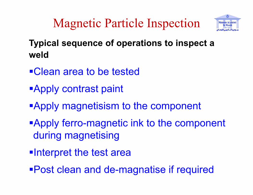
Magnetic Particle Inspection
Typical sequence of operations to inspect a
weld
Clean area to be tested
Apply contrast paint
Apply magnetisism to the component
Apply ferro-magnetic ink to the component
during magnetising
Interpret the test area
Post clean and de-magnatise if required
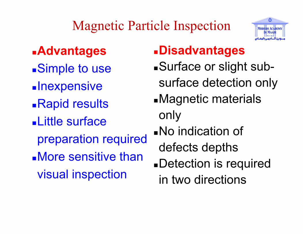
Magnetic Particle Inspection
Advantages
Simple to use
Inexpensive
Rapid results
Little surface
preparation required
More sensitive than
visual inspection
Disadvantages
Surface or slight sub-
surface detection only
Magnetic materials
only
No indication of
defects depths
Detection is required
in two directions
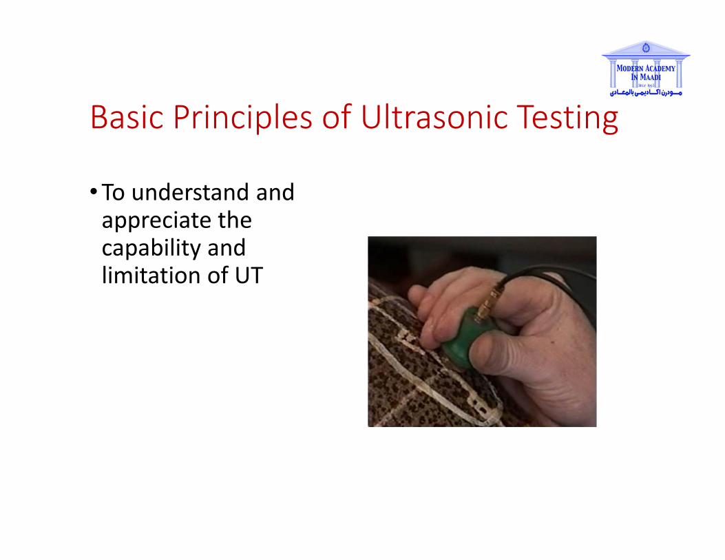
Basic Principles of Ultrasonic Testing
• To understand and
appreciate the
capability and
limitation of UT

Ultrasonic Inspection Sub-surface detection
This detection method uses high frequency sound
waves, typically above 2MHz to pass through a material
A probe is used which contains a piezo electric crystal
to transmit and receive ultrasonic pulses and display the
signals on a cathode ray tube or digital display
The actual display relates to the time taken for the
ultrasonic pulses to travel the distance to the interface
and back
An interface could be the back of a plate material or a
defect
For ultrasound to enter a material a couplant must be
introduced between the probe and specimen

Ultrasonic Inspection
Ultrasonic testing is a good technique for the
detection of plate laminations and thickness surveys
Laminations detected using compression probes
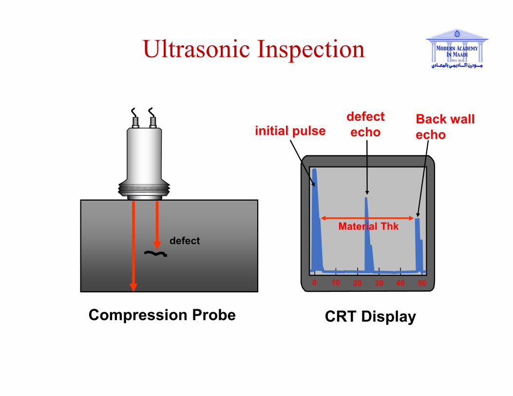
Ultrasonic Inspection
defect
0 10 20 30 40 50
defect
echoBack wall
echo
CRT DisplayCompression Probe
Material Thk
initial pulse
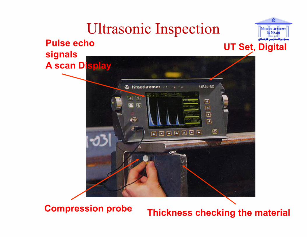
Ultrasonic InspectionUT Set, DigitalPulse echo
signals
A scan Display
Compression probe Thickness checking the material
Ultrasonic Inspection
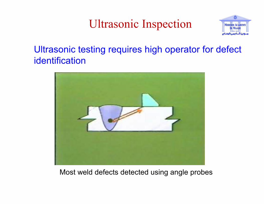
Ultrasonic testing requires high operator for defect
identification
Most weld defects detected using angle probes
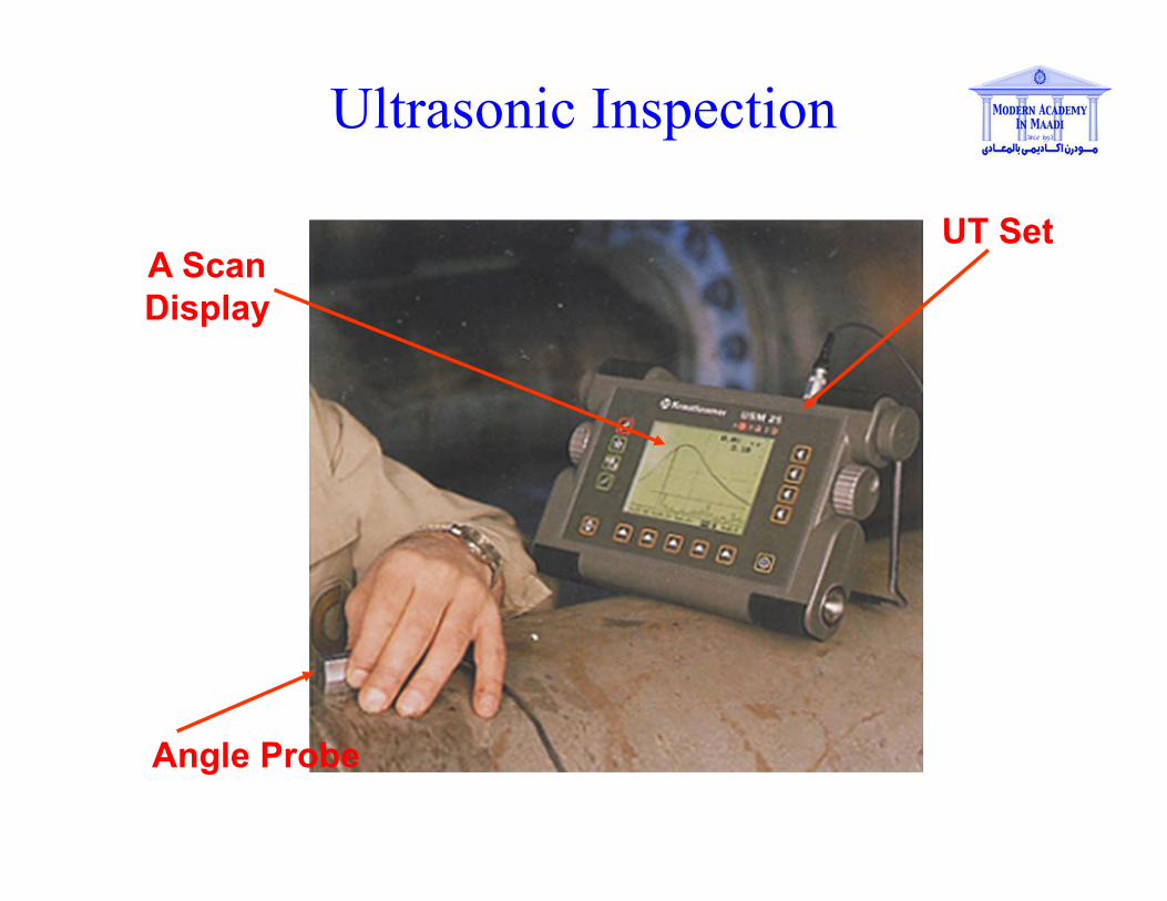
Ultrasonic Inspection
Angle Probe
UT SetA Scan
Display
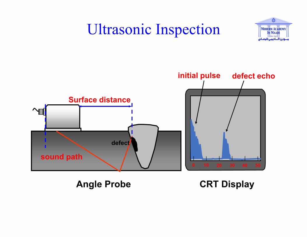
Ultrasonic Inspection
0 10 20 30 40 50
initial pulse defect echo
CRT Display
sound path
Angle Probe
defect
Surface distance
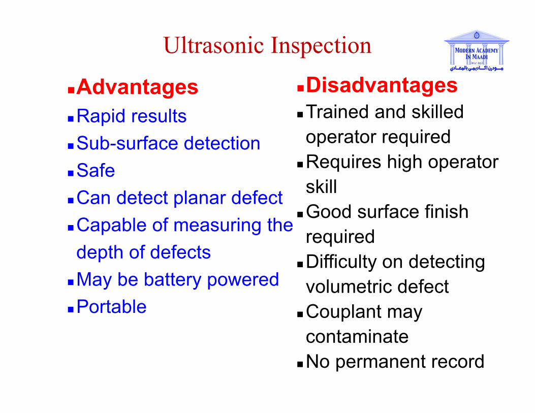
Ultrasonic Inspection
Advantages
Rapid results
Sub-surface detection
Safe
Can detect planar defect
Capable of measuring the
depth of defects
May be battery powered
Portable
Disadvantages
Trained and skilled
operator required
Requires high operator
skill
Good surface finish
required
Difficulty on detecting
volumetric defect
Couplant may
contaminate
No permanent record
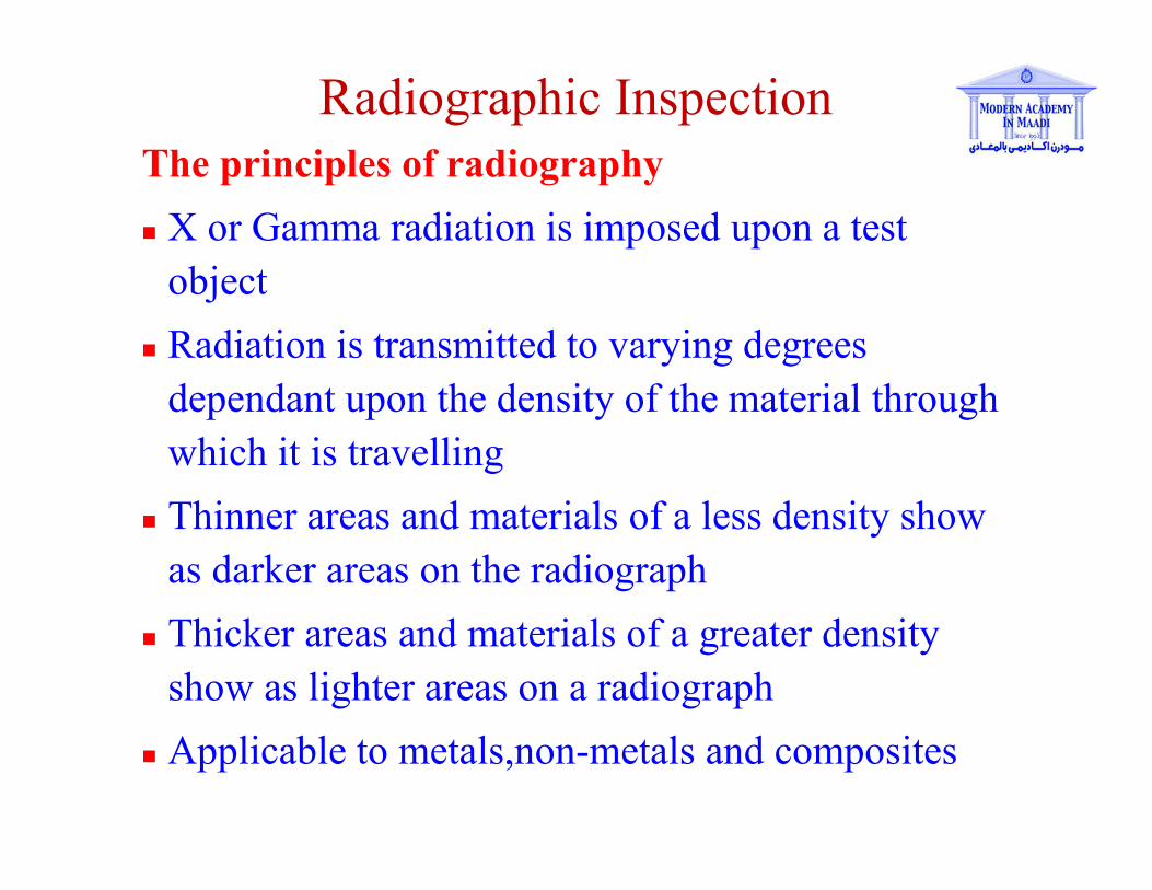
Radiographic Inspection
The principles of radiography
X or Gamma radiation is imposed upon a test
object
Radiation is transmitted to varying degrees
dependant upon the density of the material through
which it is travelling
Thinner areas and materials of a less density show
as darker areas on the radiograph
Thicker areas and materials of a greater density
show as lighter areas on a radiograph
Applicable to metals,non-metals and composites
Industrial Radiography
• X - Rays
Electrically generated
• Gamma Rays
Generated by the decay
of unstable atoms
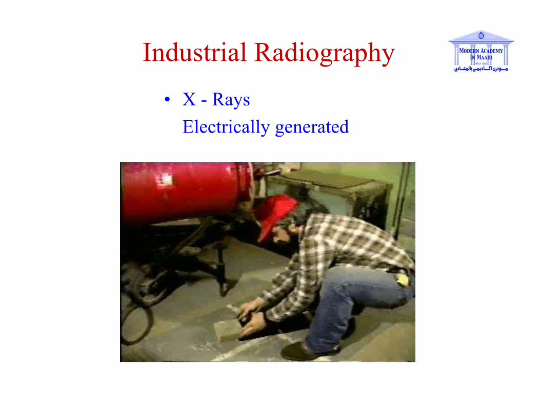
Industrial Radiography
• X - Rays
Electrically generated
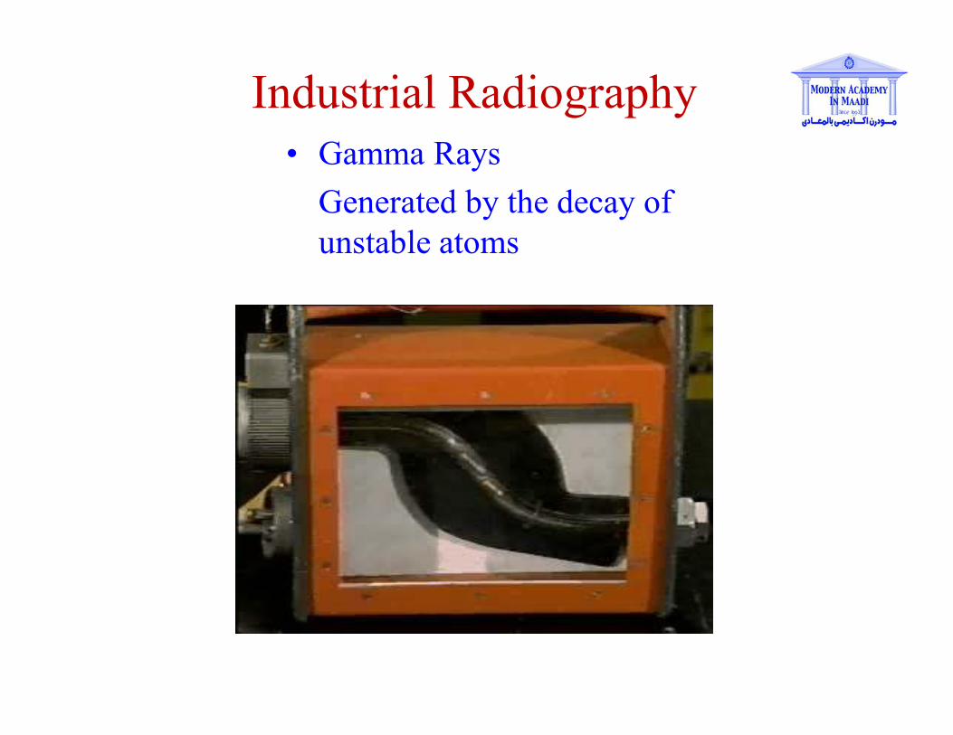
Industrial Radiography
• Gamma Rays
Generated by the decay of
unstable atoms
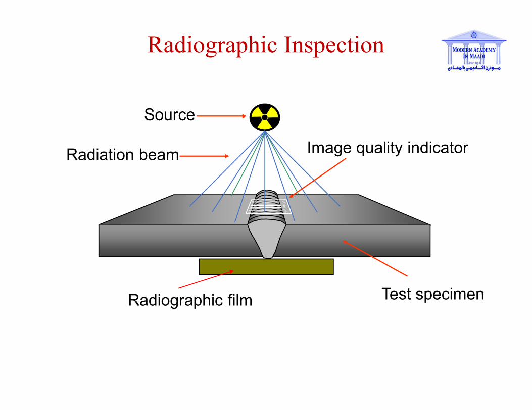
Source
Radiation beam Image quality indicator
Radiographic Inspection
Test specimenRadiographic film

Source
Radiation beam Image quality indicator
Radiographic film with latent image after exposure
Radiographic Inspection
Test specimen
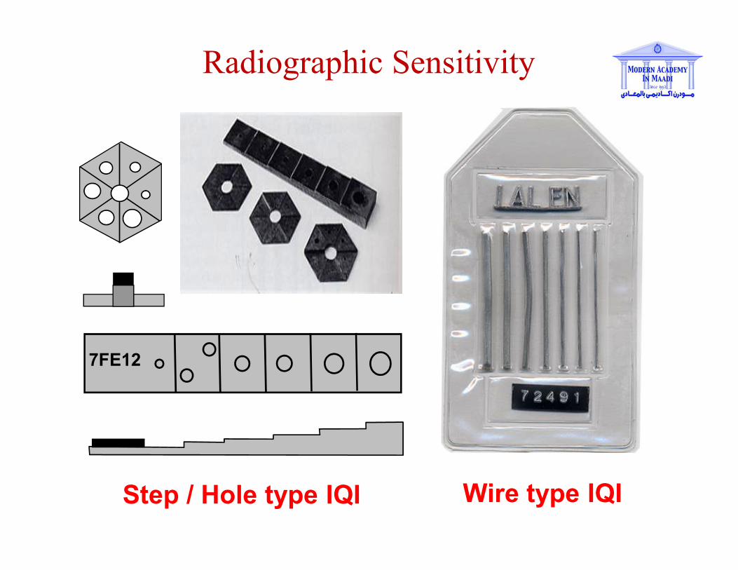
7FE12
Step / Hole type IQI Wire type IQI
Radiographic Sensitivity

Wire Type IQI
Step/Hole Type IQI
Image Quality Indicators
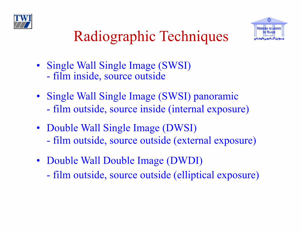
Radiographic Techniques
• Single Wall Single Image (SWSI)- film inside, source outside
• Single Wall Single Image (SWSI) panoramic
- film outside, source inside (internal exposure)
• Double Wall Single Image (DWSI)
- film outside, source outside (external exposure)
• Double Wall Double Image (DWDI)
- film outside, source outside (elliptical exposure)
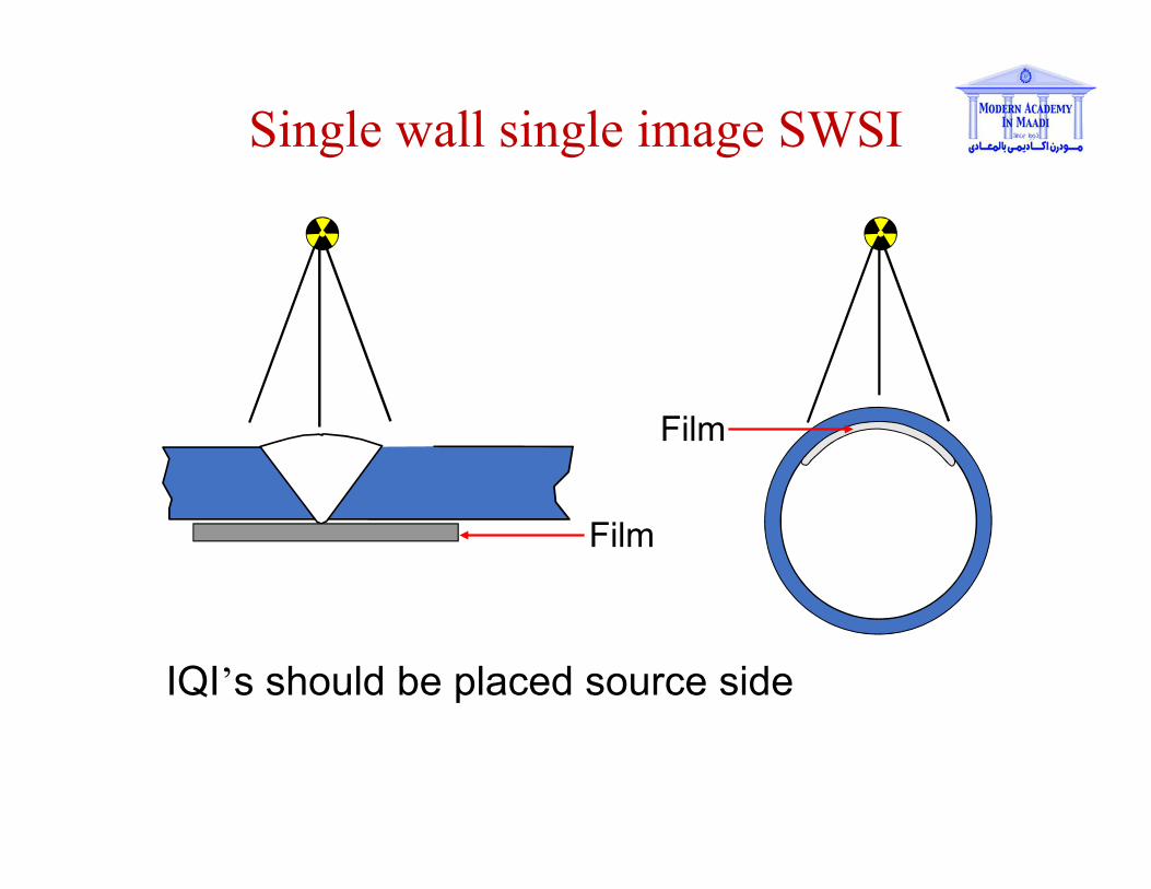
Single wall single image SWSI
IQI’s should be placed source side
Film
Film

Single wall single image SWSI panoramic
• IQI’s are placed on the film side
• Source inside film outside (single exposure)
Film

Film
Double wall single image DWSI
• IQI’s are placed on the film side
• Source outside film outside (multiple exposure)
• This technique is intended for pipe diameters over 100mm
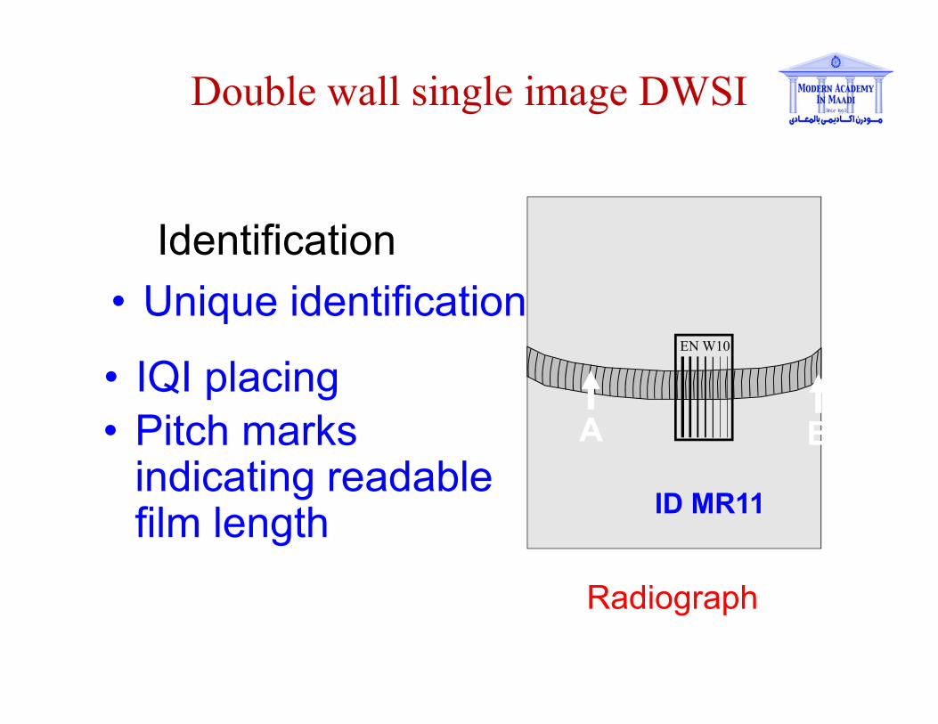
Double wall single image DWSI
Radiograph
Identification
ID MR11
• Unique identificationEN W10
• IQI placingA B• Pitch marks
indicating readable film length
Film
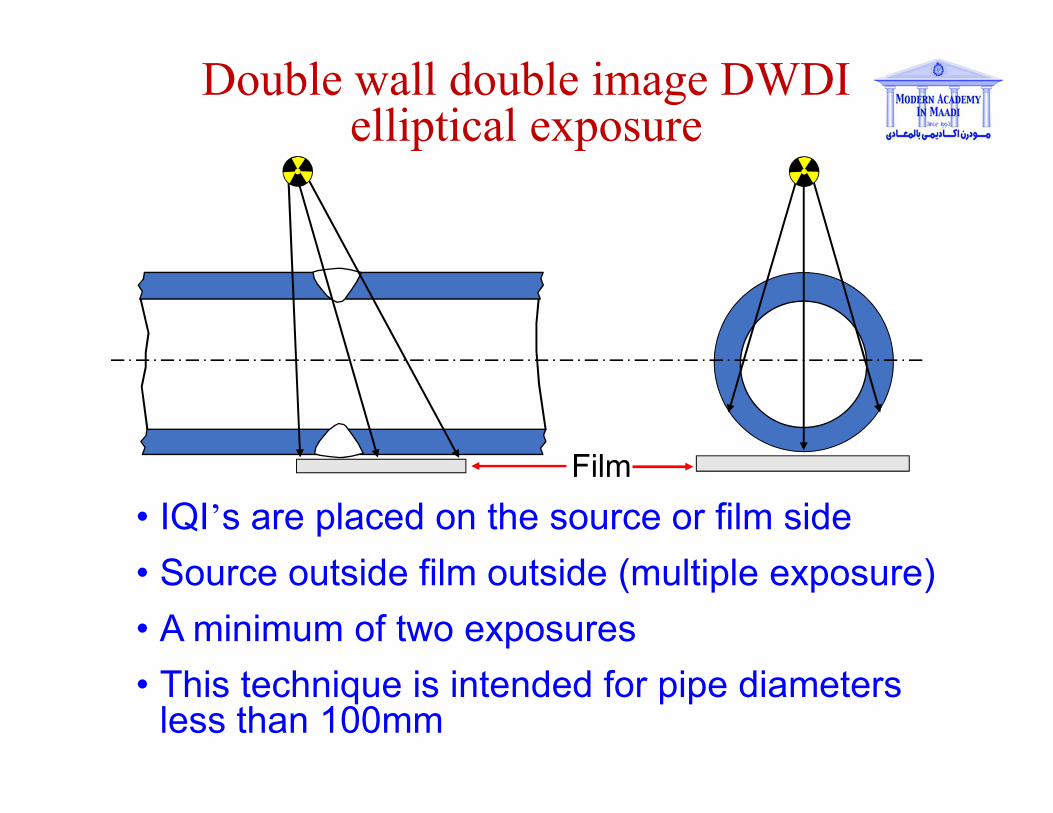
Double wall double image DWDI elliptical exposure
• IQI’s are placed on the source or film side
• Source outside film outside (multiple exposure)
• A minimum of two exposures
• This technique is intended for pipe diameters less than 100mm

Double wall double image DWDI
Shot A Radiograph
Identification
ID MR12
• Unique identification EN W10
• IQI placing
1 2• Pitch marks indicating readable film length
4 3
Radiographic Inspection
Advantages
Permanent record
Little surface preparation
Defect identification
No material type
limitation
Disadvantages
Expensive equipment
Bulky equipment ( x-ray )
Harmful radiation
Detection on defect
depending on orientation
Slow results
Required license to operate


![Cheng.modern-academy.edu.eg/e-learning/comm/Comm2 Lectures.pdfCh.[1] Analog Pulse Modulation 1.1 Introduction In Continuous-Wave (CW) Modulation: (studied previously) Some parameter](https://static.documents.pub/doc/80x56/5e74091b4517512a37200206/chengmodern-lecturespdf-ch1-analog-pulse-modulation-11-introduction-in-continuous-wave.jpg)

