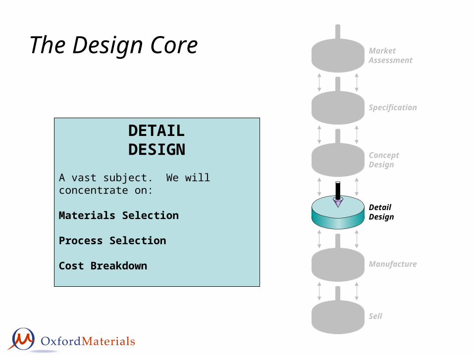
The Design Core Market Assessment Specification Concept Design Detail Design Manufacture Sell DETAIL DESIGN A vast subject. We will concentrate on: Materials Selection Process Selection Cost Breakdown
Transcript
The Design Core Market Assessment
Specification
Concept Design
Detail Design
Manufacture
Sell
DETAILDESIGN
A vast subject. We will concentrate on:
Materials Selection
Process Selection
Cost Breakdown
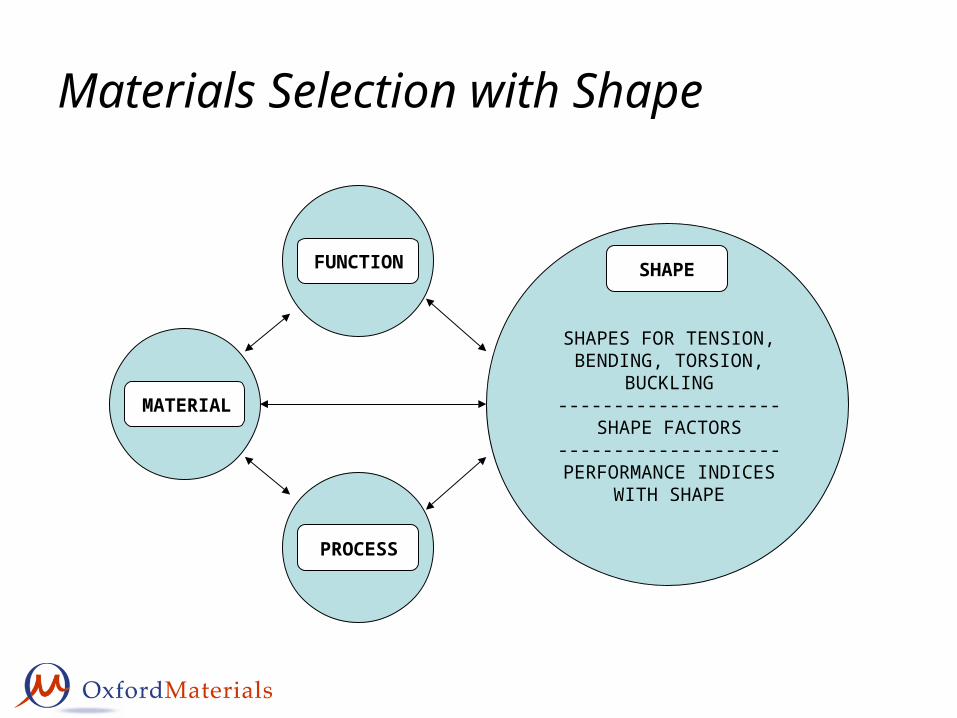
Materials Selection with Shape
FUNCTION
MATERIAL
PROCESS
SHAPE
SHAPES FOR TENSION,BENDING, TORSION,
BUCKLING--------------------
SHAPE FACTORS--------------------
PERFORMANCE INDICESWITH SHAPE
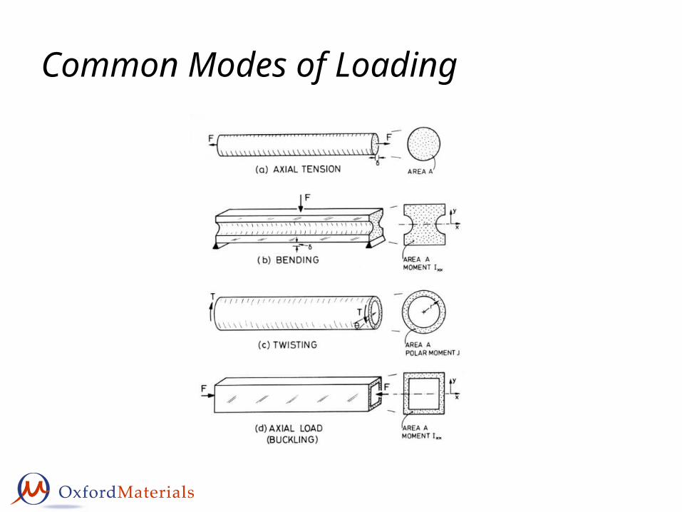
Common Modes of Loading
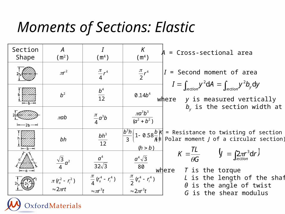
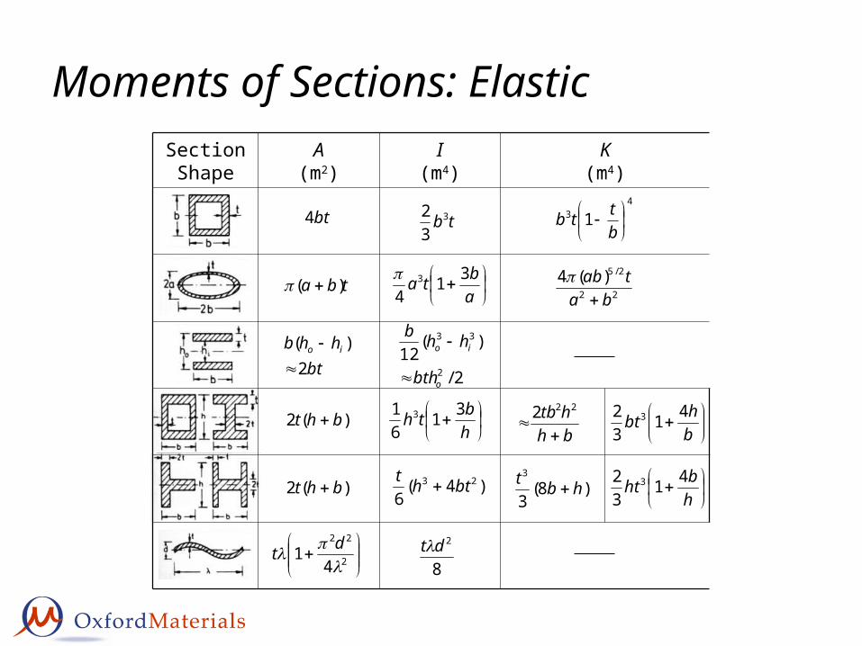
Moments of Sections: ElasticSectionShape
A(m2)
I(m4)
K(m4)
2r 4
4r 4
2r
2b 12
4b 414.0 b
ab ba3
4
)( 22
33
baba
bh12
3bh
)(
58.013
3
bhhbhb
2
43 a 332
4a80
34a
rtrr io
2)( 22
tr
rr io
3
44 )(4
tr
rr io
3
44
2
)(2
A = Cross-sectional area
I = Second moment of area
tion ytion
ybyAyIsec
2
sec
2 dd
where y is measured verticallyby is the section width at y
K = Resistance to twisting of section(≡ Polar moment J of a circular section)
tion
rrJsec
3d2G
TLK
where T is the torqueL is the length of the shaftθ is the angle of twistG is the shear modulus
Moments of Sections: Elastic
bt4
tba )(
bthhb io
2)(
)(2 bht
)(2 bht
2
22
41
dt
tb3
32
abta 31
43
2/
)(12
2
33
o
io
bth
hhb
hbth 31
61 3
)4(6
23 btht
8
2dt
43 1
bttb
22
2/5)(4ba
tab
bhhtb
222
bhbt 41
32 3
)8(3
3
hbt
hbht 41
32 3
SectionShape
A(m2)
I(m4)
K(m4)
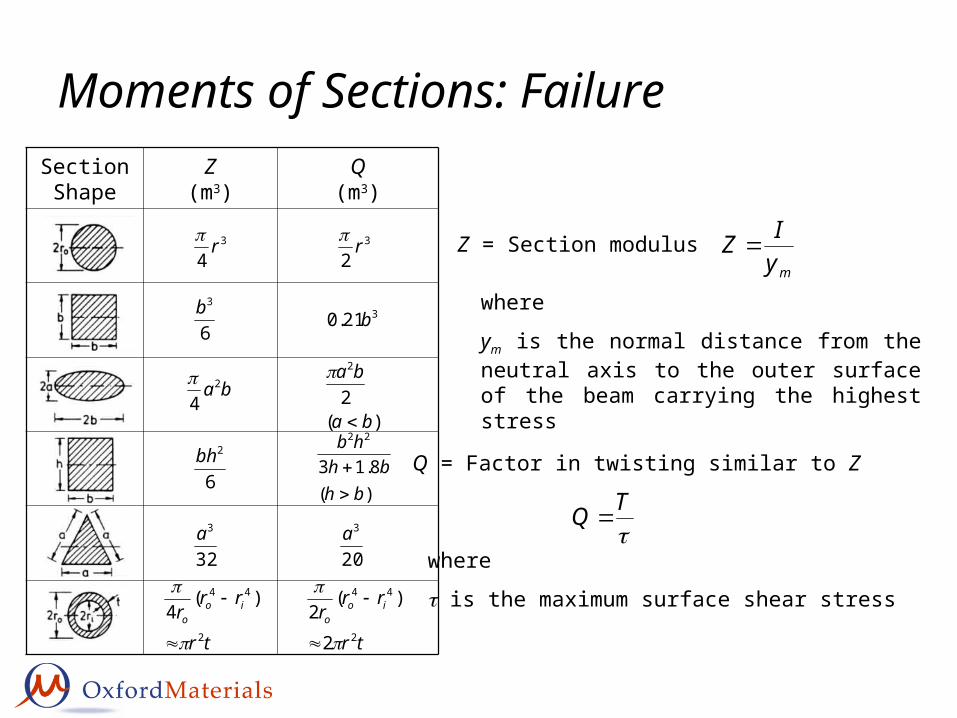
Moments of Sections: FailureSectionShape
Z(m3)
Q(m3)
3
4r 3
2r
6
3b 321.0 b
ba2
4
)(2
2
ba
ba
6
2bh
)(8.13
22
bhbh
hb
32
3a20
3a
tr
rrr ioo
2
44 )(4
tr
rrr ioo
2
44
2
)(2
Z = Section modulusmyIZ
where
ym is the normal distance from the neutral axis to the outer surface of the beam carrying the highest stress
Q = Factor in twisting similar to Z
TQ
where
is the maximum surface shear stress
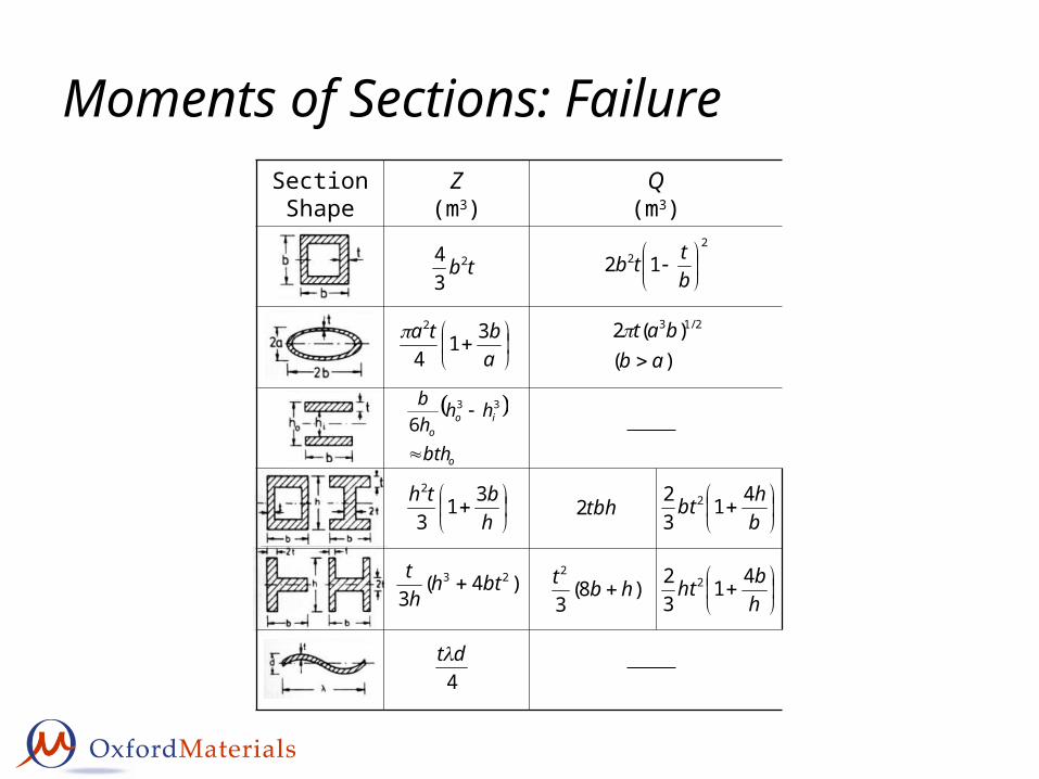
Moments of Sections: FailureSectionShape
Z(m3)
Q(m3)
tb2
34
22 12
bttb
abta 31
4
2)(
)(2 2/13
abbat
o
ioo
bth
hhhb
33
6
hbth 31
3
2
tbh2
bhbt 41
32 2
)4(3
23 bthht
)8(3
2
hbt
hbht 41
32 2
4dt
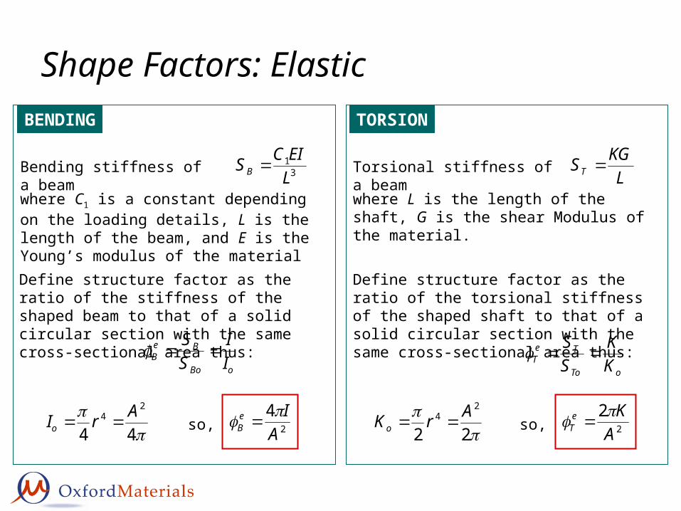
Shape Factors: ElasticBENDING
31
LEICSB
44
24 ArIo
Bending stiffness of a beam
where C1 is a constant depending on the loading details, L is the length of the beam, and E is the Young’s modulus of the material
oBo
BeB I
ISS
Define structure factor as the ratio of the stiffness of the shaped beam to that of a solid circular section with the same cross-sectional area thus:
2
4A
IeB
so,
TORSION
LKGST Torsional stiffness of a beam
where L is the length of the shaft, G is the shear Modulus of the material.
22
24 ArKo 2
2A
KeT
so,
oTo
TeT K
KSS
Define structure factor as the ratio of the torsional stiffness of the shaped shaft to that of a solid circular section with the same cross-sectional area thus:
Shape Factors: Failure/StrengthBENDING
44
2/33 ArZo
ofo
ffB Z
ZMM
Define structure factor as the ratio of the failure moment of the shaped beam to that of a solid circular section with the same cross-sectional area thus:
2/3
4A
ZfB
so,
ZM
IMym
ff ZM
The beam fails when the bending moment is large enough for σ to reach the failure stress of the material:
The highest stress, for a given bending moment M, experienced by a beam is at the surface a distance ym furthest from the neutral axis:
TORSION
QT
The highest shear stress, for a given torque T, experienced by a shaft is given by:
22
2/33 ArQo
2/3
2A
QfT
so,
ofo
ffT Q
QTT
Define structure factor as the ratio of the failure torque of the shaped shaft to that of a solid circular section with the same cross-sectional area thus:
ff QT
The beam fails when the torque is large enough for to reach the failure shear stress of the material:
Shape Factors: Failure/Strength
Please Note:The shape factors for failure/strength described in this lecture course are those defined in the 2nd Edition of “Materials Selection In Mechanical Design” by M.F. Ashby. These shape factors differ from those defined in the 1st Edition of the book. The new failure/strength shape factor definitions are the square root of the old ones.
The shape factors for the elastic case are not altered in the 2nd Edition.
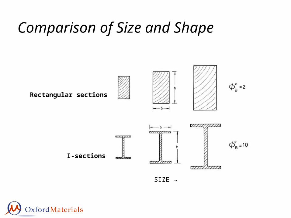
Comparison of Size and Shape
Rectangular sections
I-sections
SIZE →
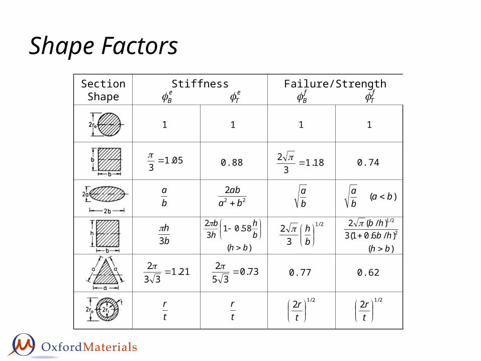
Shape FactorsSectionShape
Stiffness Failure/StrengtheB e
T fB f
T
11 11
05.13
0.88 0.7418.13
2
ba
ba )( ba
ba
22
2ba
ab
bh
3
)(
58.0132
bhbh
hb
2/1
32
bh
)()/6.01(3
)/(22
2/1
bhhb
hb
0.6221.133
2
73.035
2
2/12
tr
tr
tr 2/12
tr
0.77
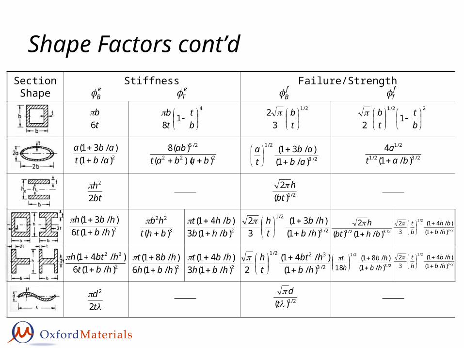
Shape Factors cont’dSectionShape
Stiffness Failure/StrengtheB e
T fB f
T
tb
6 4
18
bt
tb
2)/1()/31(
abtaba
222
2/5
))(()(8
babatab
bth
2
2
td
2
2
2)/1(6)/31(
hbthbh
2
32
)/1(6)/41(
hbthbth
3
22
)( bhthb
2)/1(3)/41(
bhbbht
2)/1(6)/81(
hbhhbt
2)/1(3)/41(
hbhhbt
2/1
32
tb 22/1
12
bt
tb
2/3
2/1
)/1()/31(
abab
ta
2/32/1
2/1
)/1(4
bata
2/1)(2
bth
2/3
2/1
)/1()/31(
32
hbhb
th
2/3
322/1
)/1()/41(
2 hbhbt
th
2/1)(
td
2/32/1 )/1()(2
bhbth
2/3
2/1
)/1()/41(
32
hbbh
bt
2/3
2/1
)/1()/81(
18 hbhb
ht
2/3
2/1
)/1()/41(
32
hbhb
ht
Efficiency of Standard Sections
2
4A
IeB
ELASTIC BENDING
Shape Factor:
4
loglog2logeBAI
Rearrange for I and take logs:
Plot logI against logA : parallel lines of slope 2e
B
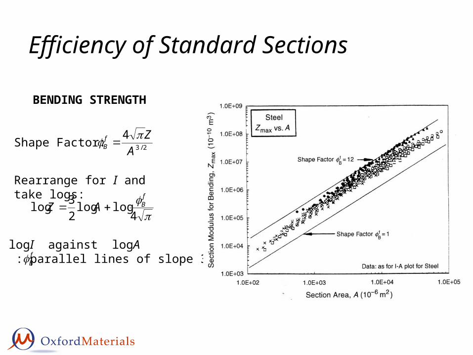
Efficiency of Standard Sections
2/3
4A
ZfB
BENDING STRENGTH
Shape Factor:
4loglog
23log
fBAZ
Rearrange for I and take logs:
Plot logI against logA : parallel lines of slope 3/2f
B
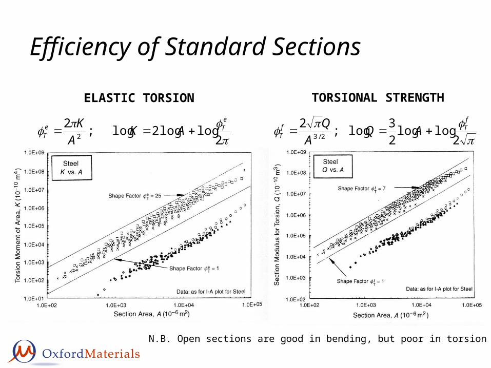
Efficiency of Standard Sections
ELASTIC TORSION
2
loglog2log;22
eTe
T AKA
K
TORSIONAL STRENGTH
2loglog
23log;2
2/3
fTf
T AQA
Q
N.B. Open sections are good in bending, but poor in torsion
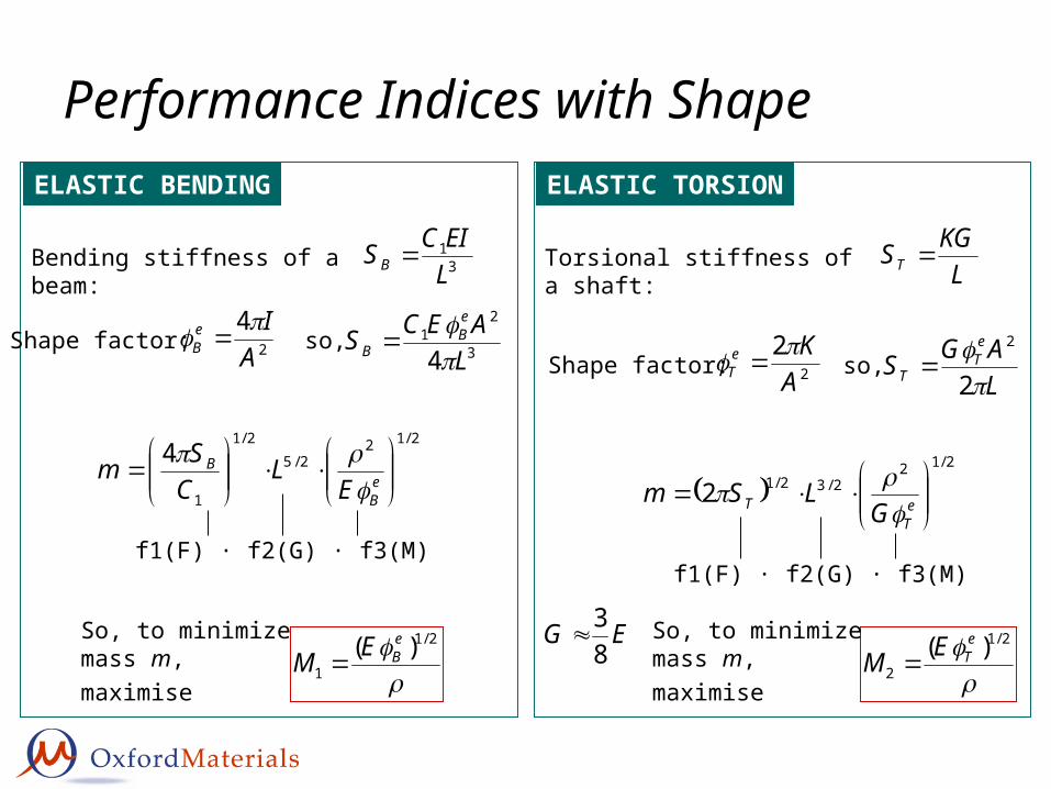
Performance Indices with ShapeELASTIC BENDING
31
LEICSB Bending stiffness of a beam:
ELASTIC TORSION
LKGST Torsional stiffness of a shaft:
2/122/5
2/1
1
4
e
B
B
EL
CSm
f1(F) · f2(G) · f3(M)
2/1
1)( e
BEM So, to minimize mass m, maximise
2
4A
IeB
Shape factor:3
21
4 LAECS
eB
B so,
2/1
2)( e
TEM So, to minimize mass m, maximise
2
2A
KeT
Shape factor:LAGS
eT
T 2
2
so,
2/12
2/32/12
e
TT G
LSm
f1(F) · f2(G) · f3(M)
EG83
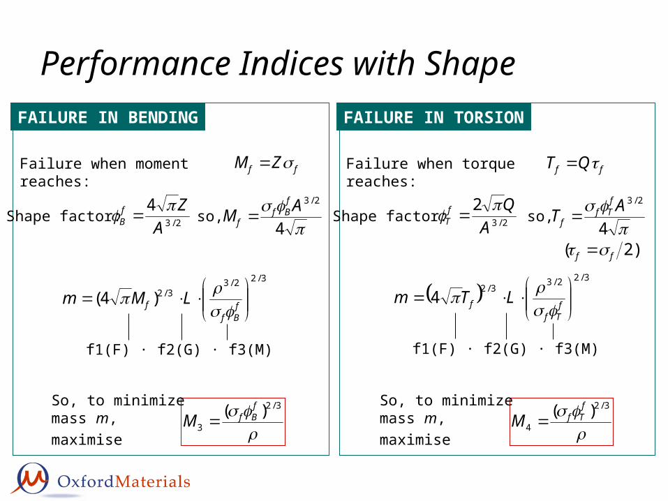
Performance Indices with ShapeFAILURE IN BENDING
ff ZM Failure when moment reaches:
FAILURE IN TORSION
ff QT Failure when torque reaches:
3/2
3)( f
BfM So, to minimize mass m, maximise
2/3
4A
ZfB
Shape factor:
4
2/3AMfBf
f so,
3/22/33/2)4(
f
Bff LMm
f1(F) · f2(G) · f3(M)
3/2
4)( f
TfM So, to minimize mass m, maximise
3/22/3
3/24
f
Tff LTm
f1(F) · f2(G) · f3(M)
2/3
2A
QfT
Shape factor:
4
2/3ATf
Tff so,
)2( ff
Shape in Materials Selection Maps
0.01
0.1
1
10
100
1000
0.1 1 10 100
Density, (Mg/m3)
You
ng's
Mod
ulus
, E (G
Pa) Engineering
Alloys
Polymer Foams
Woods
Engineering Polymers
Elastomers
Composites
CeramicsSearch Region
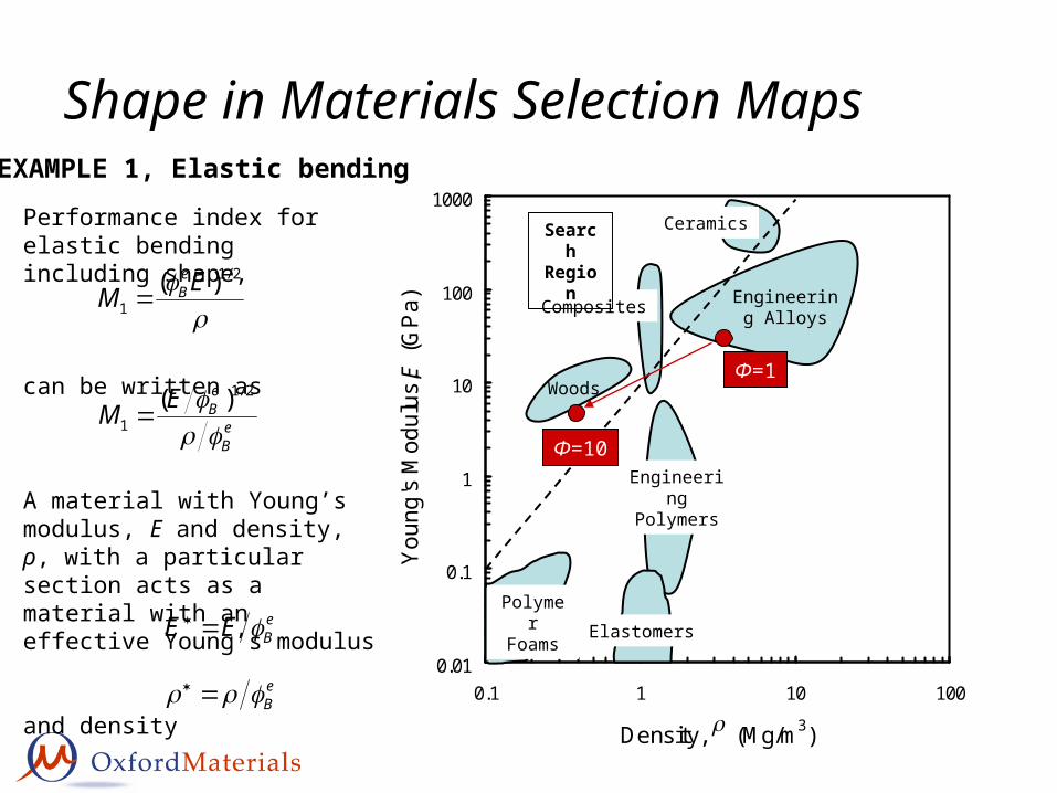
A material with Young’s modulus, E and density, ρ, with a particular section acts as a material with an effective Young’s modulus
and density
eBEE
eB
Performance index for elastic bending including shape,
can be written as
2/1
1)( EM
eB
eB
eBEM
2/1
1)(
EXAMPLE 1, Elastic bending
Φ=1
Φ=10
Shape in Materials Selection Maps
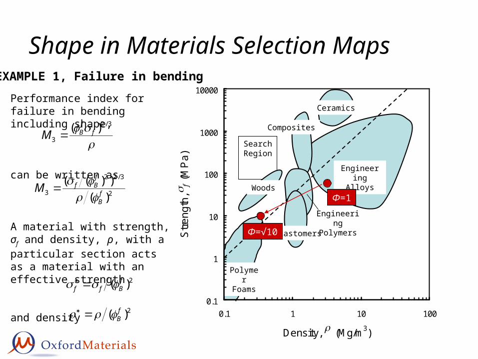
A material with strength, σf and density, ρ, with a particular section acts as a material with an effective strength
and density
2)( fBff
2)( fB
Performance index for failure in bending including shape,
can be written as
3/2
3)( f
fBM
2
3/22
3 )())((
fB
fBfM
EXAMPLE 1, Failure in bending
Engineering Alloys
Polymer Foams
0.1
1
10
100
1000
10000
0.1 1 10 100
Density, (Mg/m3)
Stre
ngth
, f (
MP
a)
Ceramics
Composites
Search Region
Woods
Elastomers
Engineering Polymers
Φ=1
Φ=√10
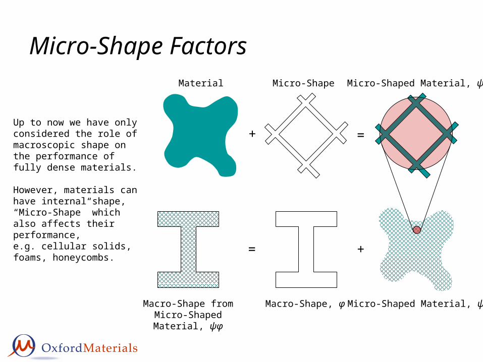
Micro-Shape FactorsMaterial Micro-Shape
+
Macro-Shape, φ
+
Macro-Shape fromMicro-Shaped Material,
ψφ
=
Up to now we have only considered the role of macroscopic shape on the performance of fully dense materials.
However, materials can have internal shape, “Micro-Shape” which also affects their performance,e.g. cellular solids, foams, honeycombs.
Micro-Shaped Material, ψ
=
Micro-Shaped Material, ψ
Micro-Shape Factors
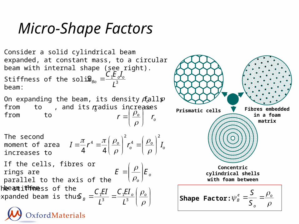
Prismatic cells
Concentric cylindrical shells with foam between
Fibres embedded in a foam matrix
Consider a solid cylindrical beam expanded, at constant mass, to a circular beam with internal shape (see right).
Stiffness of the solid beam: 31
LIECS oo
Bo
On expanding the beam, its density falls from to , and its radius increases from to
o
oo rr
2/1
or
oo
oo IrrI
24
24
44
The second moment
of area increases to
oo
EE
If the cells, fibres or rings are
parallel to the axis of the beam then
The stiffness of theexpanded beam is thus
oo
B LEIC
LEICS 3
13
1 Shape Factor: o
o
eB S
S
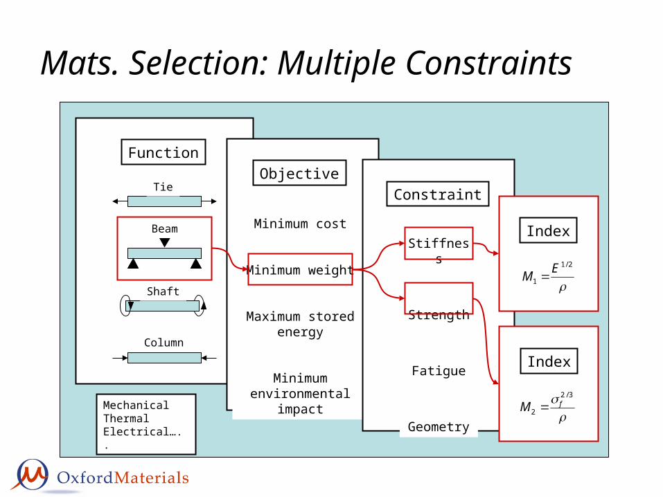
Function
Tie
Beam
Column
Shaft
Mats. Selection: Multiple Constraints
Objective
Minimum cost
Minimum weight
Maximum stored energy
Minimum environmental
impact
Constraint
Stiffness
Strength
Fatigue
GeometryMechanicalThermalElectrical…..
Index
2/1
1EM
Index
3/2
2fM
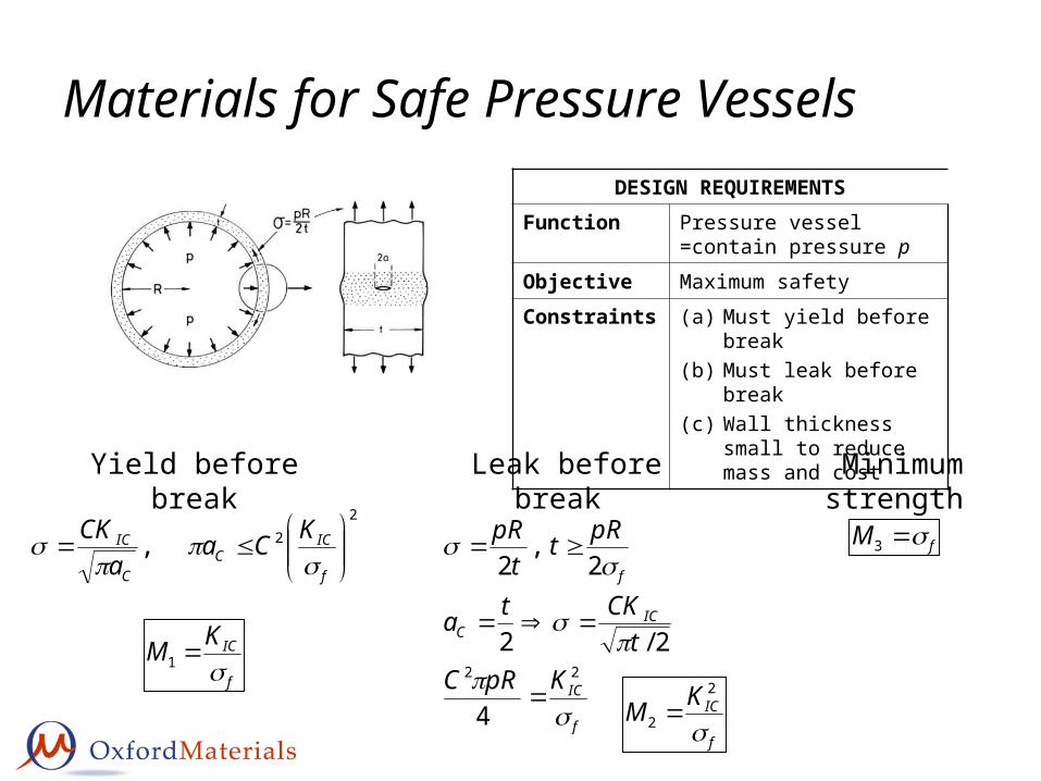
Materials for Safe Pressure VesselsDESIGN REQUIREMENTS
Function Pressure vessel =contain pressure p
Objective Maximum safety
Constraints (a) Must yield before break(b) Must leak before break(c) Wall thickness small to
reduce mass and cost
Yield before break2
2,
f
ICC
C
IC KCaa
CK
f
ICKM
1
Leak before break
f
IC
ICC
f
KpRCt
CKta
pRtt
pR
22
4
2/2
2,
2
f
ICKM
2
2
Minimum strength
fM 3
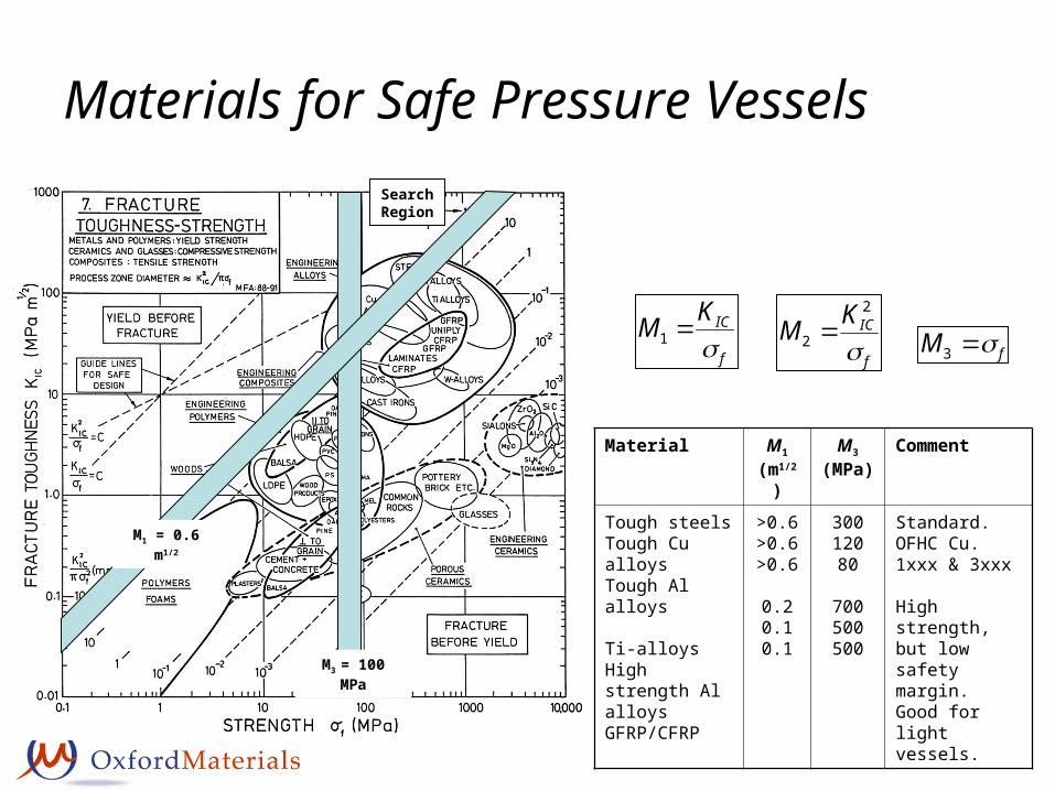
Materials for Safe Pressure VesselsSearchRegion
M3 = 100 MPa
M1 = 0.6 m1/2
f
ICKM
1f
ICKM
2
2 fM 3
Material M1
(m1/2)M3
(MPa)Comment
Tough steelsTough Cu alloysTough Al alloys
Ti-alloysHigh strength Al alloysGFRP/CFRP
>0.6>0.6>0.6
0.20.10.1
30012080
700500500
Standard.OFHC Cu.1xxx & 3xxx
High strength, but low safety margin. Good for light vessels.
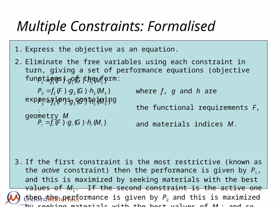
1. Express the objective as an equation.
2. Eliminate the free variables using each constraint in turn, giving a set of performance equations (objective functions) of the form:
where f, g and h are expressions containing
the functional requirements F, geometry M
and materials indices M.
3. If the first constraint is the most restrictive (known as the active constraint) then the performance is given by P1, and this is maximized by seeking materials with the best values of M1. If the second constraint is the active one then the performance is given by P2 and this is maximized by seeking materials with the best values of M2; and so on.
N.B. For a given Function the Active Constraint will be material dependent.
Multiple Constraints: Formalised
)()()(
)()()()()()(
)()()(
33333
22222
11111
iiiii MhGgFfP
MhGgFfPMhGgFfP
MhGgFfP
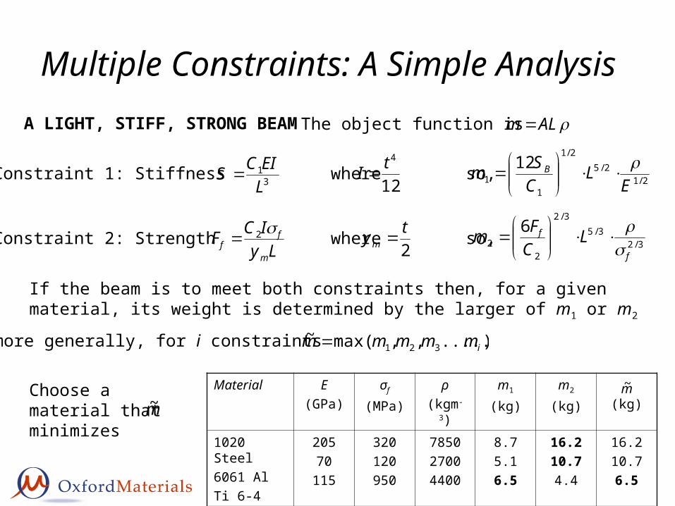
Multiple Constraints: A Simple AnalysisA LIGHT, STIFF, STRONG BEAM The object function is ALm
Constraint 1: Stiffness where so,31
LEICS
12
4tI 2/12/5
2/1
11
12E
LCSm B
Constraint 2: Strength where so,Ly
ICFm
ff
22tym 3/2
3/53/2
22
6
f
f LCFm
If the beam is to meet both constraints then, for a given material, its weight is determined by the larger of m1 or m2
or more generally, for i constraints ).....,,max(~321 immmmm
Material E(GPa)
σf
(MPa)
ρ(kgm-3)
m1
(kg)
m2
(kg) (kg)
1020 Steel6061 AlTi 6-4
20570
115
320120950
785027004400
8.75.16.5
16.210.74.4
16.210.76.5
m~Choose a material that minimizes m~
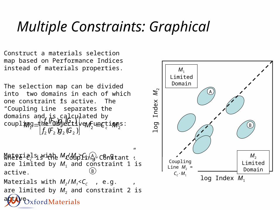
Multiple Constraints: Graphical
log Index M1
log
Inde
x M
2
Construct a materials selection map based on Performance Indices instead of materials properties.
The selection map can be divided into two domains in each of which one constraint is active. The “Coupling Line” separates the domains and is calculated by coupling the Objective Functions:
where CC is the “Coupling Constant”.
222222
11111 )()(
)()( MCMGgFfGgFfM c
Coupling Line M2 = CC·M1
M1 Limited Domain
M2 Limited Domain
A
B
Materials with M2/M1>CC , e.g. , are limited by M1 and constraint 1 is active.
Materials with M2/M1<CC , e.g. , are limited by M2 and constraint 2 is active.
A
B
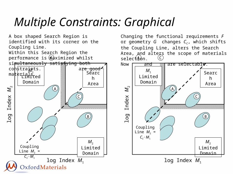
Multiple Constraints: Graphical
Coupling Line M2 = CC·M1
Search Area
C
log Index M1
log
Inde
x M
2
M1 Limited Domain
M2 Limited Domain
A
B
C
C
A box shaped Search Region is identified with its corner on the Coupling Line.Within this Search Region the performance is maximized whilst simultaneously satisfying both constraints. are good materials.
M1 Limited Domain
M2 Limited Domain
A
B
Coupling Line M2 = CC·M1
log Index M1
log
Inde
x M
2
C
Search Area
A C
Changing the functional requirements F or geometry G changes CC, which shifts the Coupling Line, alters the Search Area, and alters the scope of materials selection.Now and are selectable.
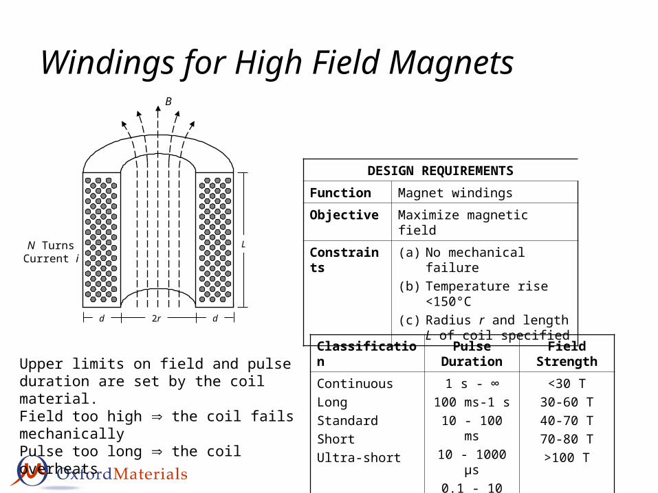
Windings for High Field Magnets
DESIGN REQUIREMENTSFunction Magnet windings
Objective Maximize magnetic field
Constraints (a) No mechanical failure(b) Temperature rise <150°C(c) Radius r and length L of
coil specified
2r dd
LN TurnsCurrent i
B
Upper limits on field and pulse duration are set by the coil material.Field too high the coil fails mechanicallyPulse too long the coil overheats
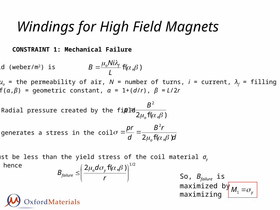
where μo = the permeability of air, N = number of turns, i = current, λf = filling factor,f(α,β) = geometric constant, α = 1+(d/r), β = L/2r
CONSTRAINT 1: Mechanical Failure
Radial pressure created by the field
generates a stress in the coil
),(f2
2
o
Bp
drB
dpr
o ),(f2
2
σ must be less than the yield stress of the coil material σy
and hence 2/1),(f2
rd
B yofailure
So, Bfailure is maximized by maximizing
yM 1
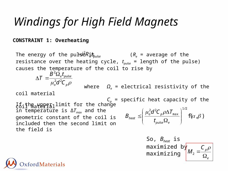
Windings for High Field MagnetsCONSTRAINT 1: Overheating
So, Bheat is maximized by maximizing
e
pCM
2
The energy of the pulse is (Re = average of the resistance over the heating cycle, tpulse = length of the pulse) causes the temperature of the coil to rise by
where Ωe = electrical resistivity of the coil materialCp = specific heat capacity of the coil material
pulseetRi 2
po
pulsee
CdtB
T 22
2
If the upper limit for the change in temperature is ΔTmax and the geometric constant of the coil is included then the second limit on the field is ),(f
2/1
max22
epulse
poheat t
TCdB
Windings for High Field Magnets
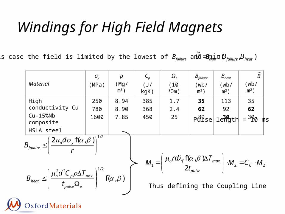
Materialσy
(MPa)
ρ(Mg/m3)
Cp
(J/kgK)
Ωe
(10-8Ωm)
Bfailure
(wb/m2)
Bheat
(wb/m2) (wb/m2)
High conductivity CuCu-15%Nb compositeHSLA steel
250780
1600
8.948.907.85
385368450
1.72.425
356289
1139230
356230
Pulse length = 10 ms
B~
),min(~heatfailure BBB In this case the field is limited by the lowest of Bfailure and Bheat: e.g.
),(f2/1
max22
epulse
poheat t
TCdB
2/1),(f2
rd
B yofailure
221 2),(f MCM
tTrdM C
pulse
maxfo
Thus defining the Coupling Line
10
100
1000
10000
100 1000 10000Index M 2 (10-8 m3/J)
Inde
x M
1 (M
Pa)
Search Region:Ultra-short pulse
Search Region:long pulse
Search Region:short pulse
HSLA steels
CuAl-S150.1
Cu-4Sn
Cu-Be-Co-Ni
Be-Coppers
GP coppers
HC Coppers
Cu-NbCu-Al2O3
Cu-Zr
Windings for High Field Magnets
Material Comment
Continuous and long pulseHigh purity coppersPure Silver