MATERIALS TO RESIST THE ABRASION OF PNEUMATICALL Y TRANSPORTED PROCESSED REFUSE JAMES D. MURPHY Union Electric Company St. Louis. Missouri ABSTRACT This paper describes the preliminary evaluation of the effectiveness of some materials used to combat the erosion by processed refuse in pneu- matic transport pipes. These transport pipes are part of a prototype operation for processing solid waste as a supplementary fuel for electric utility boilers and for the recovery of recyclable non- combustible materials. INTRODUCTION A full scale test program, called the Energy Re- covery Project, had been conducted by the City of St. Louis, Missouri and the Union Electric Com- pany to determine the feasibility of burning proc- essed household refuse, along with pulverized coal, in an electric utility boiler. The program had been operated from April, 1972, throu November, 1975, with intermittent shutdowns for equipment problems, construction work, maintenance work and labor strikes. A total of 48,972 tons (44,457 t) of processed refuse were burned in the boilers during this period. The operation entailed the collection, milling, and air classifying of raw municipal solid waste by the city with the remaining combustible fraction being transported pneumatically by Union ectric to a 140 MW unit boiler. Operation of the prototype system during the first year was satisfactory, except for problems with the mechanical equipment that handled the 327 milled refuse. Throughout this period, only mag- netic metals were removed from the refuse before firing in the boiler. Solid, nonmagnetic pieces fre- quently caused the jamming of the air-lock feeders that supplied the material to the pneumatic trans- port system. Crushed glass and other abrasive ma- terials in the solid waste caused excessive wear in the pipe bends of the pneumatic system. The quantity of combustible and noncombustible mat- ter removed with the boiler bottom ash was ex- • ceSSlVe. The problems became evident soon after the initial operation of the system. An air classifier was purchased and installed in late 1973 to re- move glass, metals, and other unburnable objects. The classifier successfully removed the larger ma- terial that caused feeder jamming, but the re- maining smal l particles of glass continued to erode the recently replaced pipe bends at the same rate as before the installation of the classifier. A pro- gram was initiated to find materials for use in the pneumatic pipelines to resist the abrasion of the glass that was still contained in the refuse after classification. The results of this program are de- scribed in the following sections of this paper. MATERIALS FOR RESISTING SOLID WASTE ABRASION As mentioned previously, the crushed glass and other abrasive materials contained with the proc- essed refuse severely eroded the carbon steel pipe bends of the pneumatic pipeline at the supple-
Transcript
MATERIALS TO RESIST THE ABRASION OF
PNEUMATICALL Y TRANSPORTED PROCESSED REFUSE
JAMES D. MURPHY Union Electric Company
St. Louis. Missouri
ABSTRACT
This paper describes the preliminary evaluation of the effectiveness of some materials used to combat the erosion by processed refuse in pneumatic transport pipes. These transport pipes are
part of a prototype operation for processing solid
waste as a supplementary fuel for electric utility
boilers and for the recovery of recyclable non
combustible materials.
INTRODUCTION
A full scale test program, called the Energy Recovery Project, had been conducted by the City of St. Louis, Missouri and the Union Electric Company to determine the feasibility of burning proc
essed household refuse, along with pulverized coal,
in an electric utility boiler. The program had been operated from April, 1972, through November, 1975, with intermittent shutdowns for equipment problems, construction work, maintenance work
and labor strikes. A total of 48,972 tons (44,457 t) of processed refuse were burned in the boilers during this period. The operation entailed the collection, milling, and air classifying of raw municipal solid waste by the city with the remaining combustible fraction being transported pneumatically by Union
Electric to a 140 MW unit boiler.
Operation of the prototype system during the
first year was satisfactory, except for problems with the mechanical equipment that handled the
327
milled refuse. Throughout this period, only mag
netic metals were removed from the refuse before firing in the boiler. Solid, nonmagnetic pieces frequently caused the jamming of the air-lock feeders that supplied the material to the pneumatic transport system. Crushed glass and other abrasive materials in the solid waste caused excessive wear in
the pipe bends of the pneumatic system. The
quantity of combustible and noncombustible mat
ter removed with the boiler bottom ash was ex-•
ceSSlVe.
The problems became evident soon after the initial operation of the system. An air classifier was purchased and installed in late 1973 to remove glass, metals, and other unburnable objects. The classifier successfully removed the larger material that caused feeder jamming, but the remaining small particles of glass continued to erode
the recently replaced pipe bends at the same rate
as before the installation of the classifier. A program was initiated to find materials for use in the pneumatic pipelines to resist the abrasion of the glass that was still contained in the refuse after classification. The results of this program are de
scribed in the following sections of this paper.
MATERIALS FOR RESISTING
SOLID WASTE ABRASION
As mentioned previously, the crushed glass and other abrasive materials contained with the proc
essed refuse severely eroded the carbon steel pipe bends of the pneumatic pipeline at the supple-
mentary fuel receiving station. This problem became evident several weeks after the initial operation of the prototype system. It was decided that a program should be carried out to determine if any of the available wear-resistant materials on the market could be used to eliminate the erosion caused by the abrasive materials in the refuse. Also, it was hoped that the air classifier would remove this abrasive material, thus eliminating the largest maintenance item for U.E. personnel.at the Meramec Plant. After the air classifier became operational in November, 1973, it was quite apparent that the abrasive material that was causing the damage had not been completely removed from the refuse. The new pipe bends that had been installed while the air classifier was being constructed were having holes worn in them at the same rate as that prior to the operation of the air classifier. Examination of the heavy rejects from the classifier showed that large pieces of glass, about 1/8 in. diameter and greater, had been removed from the processed solid waste. However, inspection of the milled refuse delivered to the power plant revealed that fine grains of glass, 1/16 in. and smaller, and other abrasive substances were still part of the material that was being blown through the pipelines.
Based on the existing technology, it was assumed that these fine grains of glass and abrasive materials could not be economically removed from the solid waste. Hence, the program for finding a wear-resistant material was stepped up.
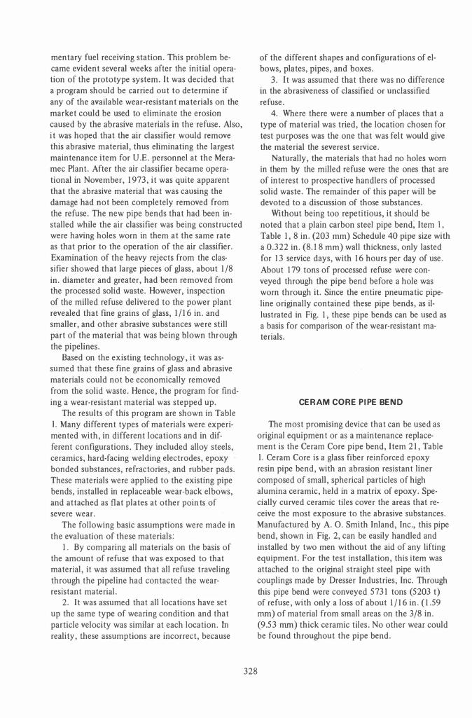
The results of this program are shown in Table l. Many different types of materials were experimented with, in different locations and in different configurations. They included alloy steels, ceramics, hard-facing welding electrodes, epoxy bonded substances, refractories, and rubber pads. These materials were applied to the existing pipe bends, installed in replaceable wear-back elbows, and attached as flat plates at other poin ts of severe wear.
The following basic assumptions were made in the evaluation of these materials:
1. By comparing all materials on the basis of the amount of refuse that was exposed to that material, it was assumed that all refuse traveling through the pipeline had contacted the wearresistant material.
2. It was assumed that all locations have set up the same type of wearing condition and that particle velocity was similar at each location. In
reality, these assumptions are incorrect, because
328
of the different shapes and configurations of elbows, plates, pipes, and boxes.
3. It was assumed that there was no difference in the abrasiveness of classified or unclassified refuse.
4. Where there were a number of places that a type of material was tried, the location chosen for test purposes was the one that was felt would give the material the severest service.
Naturally, the materials that had no holes worn in them by the milled refuse were the ones that are of interest to prospective handlers of processed solid waste. The remainder of this paper will be devoted to a discussion of those substances.
Without being too repetitious, it should be noted that a plain carbon steel pipe bend; Item I,
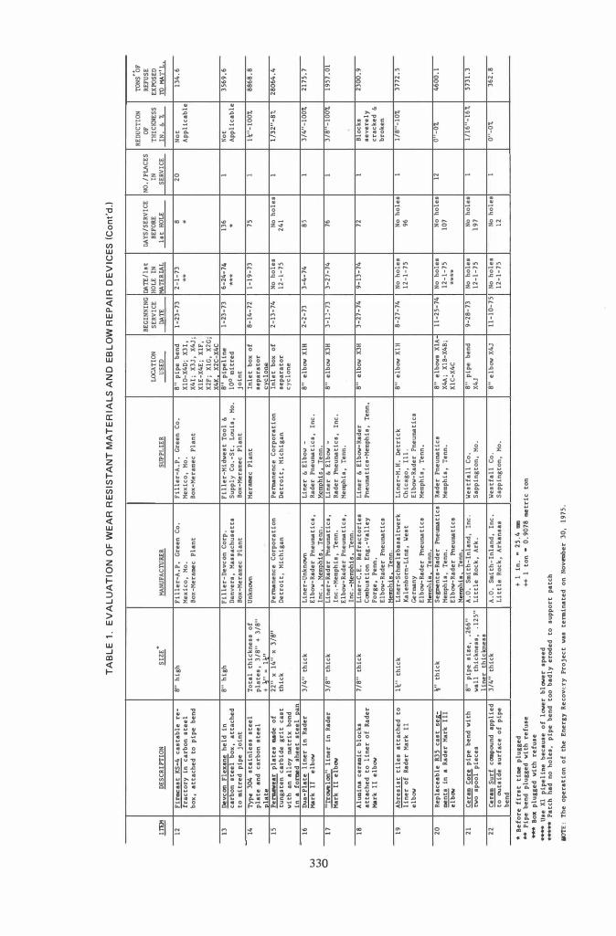
Table 1,8 in. (203 mm) Schedule 40 pipe size with a 0.322 in. (8.18 mm) wall thickness, only lasted for 13 service days, with 16 hours per day of use. About 179 tons of processed refuse were conveyed through the pipe bend before a hole was worn through it. Since the entire pneumatic pipeline originally contained these pipe bends, as illustrated in Fig. 1, these pipe bends can be used as a basis for comparison of the wear-resistant materials.
CERAM CORE PIPE BEND
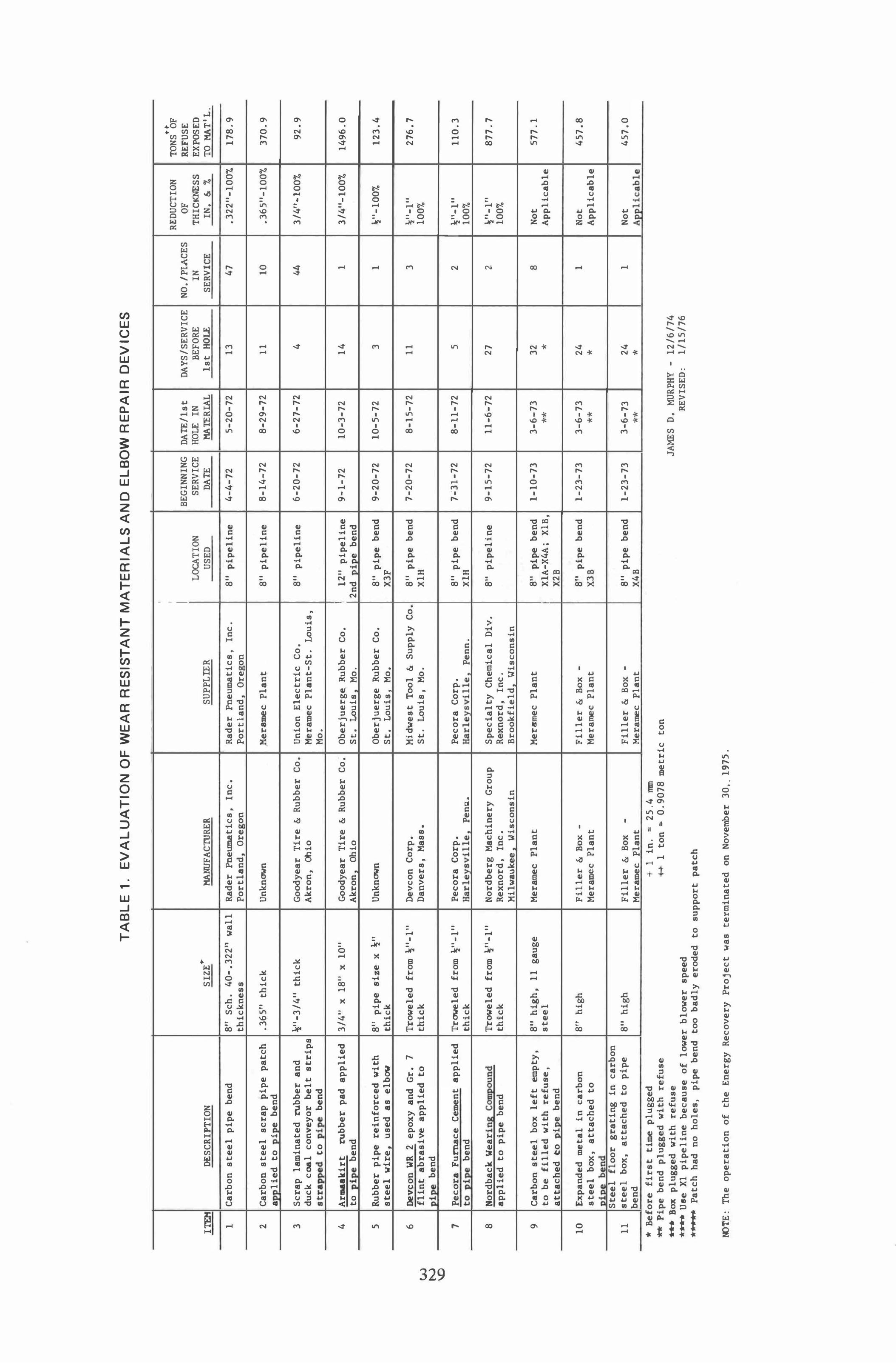
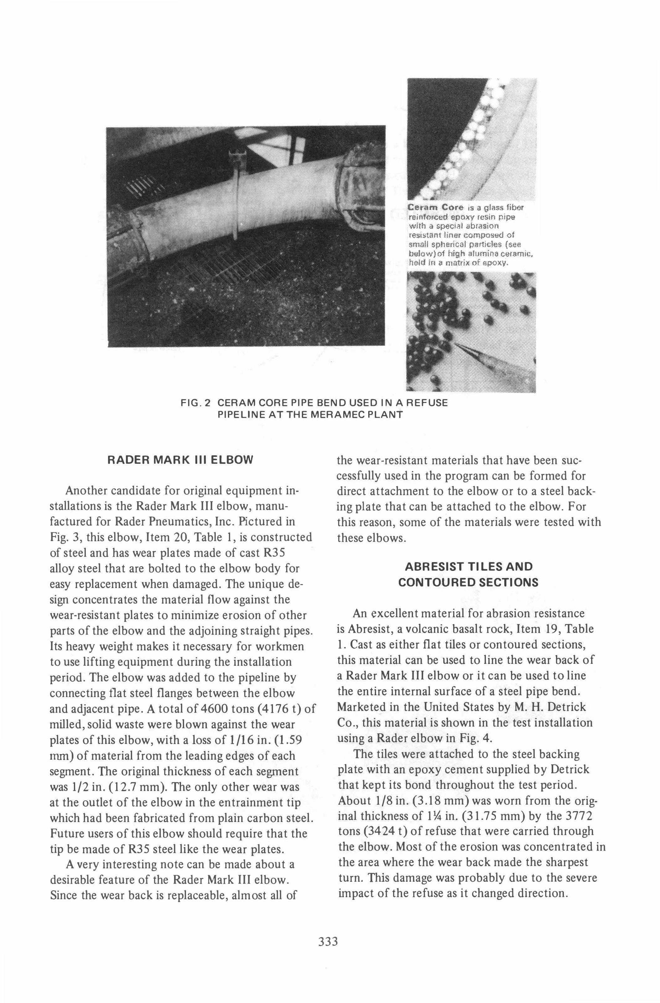
The most promising device that can be used as original equipmen t or as a maintenance replacement is the Ceram Core pipe bend, Item 21, Table l. Ceram Core is a glass fiber reinforced epoxy resin pipe bend, with an abrasion resistant liner composed of small, spherical particles of high alumina ceramic, held in a matrix of epoxy. Specially curved ceramic tiles cover the areas that receive the most exposure to the abrasive substances. Manufactured by A. O. Smith Inland, Inc., this pipe bend, shown in Fig. 2, can be easily handled and installed by two men without the aid of any lifting equipment. For the test installation, this item was attached to the original straight steel pipe with couplings made by Dresser Industries, Inc. Through this pipe bend were conveyed 5731 tons (5203 t) of refuse, with only a loss of about 1/16 in. (1.59 mm) of material from small areas on the 3/8 in. (9.53 mm) thick ceramic tiles. No other wear could be found throughout the pipe bend.
W
tv
\D
TA
BL
E 1
. E
VA
LU
AT
ION
OF
WE
AR
RE
SIS
TA
NT
MA
TE
RIA
LS
AN
D E
LB
OW
RE
PA
IR D
EV
ICE
S
ITEM
DESC
RIPT
ION
SIZE
T MA
NUF A
CTIJRE
R
1 Ca
rbon
ste
el p
ipe
bend
8"
Sch
. 40
-.32
211
wall
Ra
der
Pneuma
tics
� In
c.
thic
knes
s Po
rtla
nd
Ore
on
2 Ca
rbon
ste
el s
crap
pip
e pa
tch
.365
" th
ick
Unkn
own
a li
ed t
o 1
e
bend
3 Sc
rap
lami
nate
d ru
bber
and
\:"
-3/4
" th
ick
Good
year
Tir
e &
Rubb
er C
o.
duck
coa
l co
nvey
or b
elt
stri
ps
Akro
n,
Ohio
st
rapped
to p
ipe
bend
4 Ar
maak
irt
rubb
er p
ad a
ppli
ed
3/4"
x 1
811
x 10
" Go
odye
ar T
ire
& Ru
bber
Co.
to
pip
e be
nd
Akro
n Oh
io
5 Ru
bber
pip
e re
info
rced
wit
h 81
1 pi
pe s
ize
x �I
I Un
know
n st
eel
wire
, us
ed a
s el
bow
thic
k
6 De
vcon
WR
2 ep
oxy
and
Gr.
7 Tr
owel
ed f
rom
�"-l
" De
vcon
Cor
p.
flin
t ab
rasi
ve a
ppli
ed t
o th
ick
Danv
ers,
Mas
s.
� ben
d
7
Peco
ra F
urnace
Cem
ent
appl
ied
Trow
eled
fro
m �"
-l"
Peco
ra C
orp.
to
.R..!l!! b
end
thic
k Ha
rley
svil
le
PenQ
.
8 No
rdba
ck W
ear i
ns C
Oblpoun
d Tr
owel
ed f
rom
�"-l
" No
rdbe
rg M
achi
nery
Gro
up
appl
ied
to p
ipe
bend
th
ick
Rexn
ord.
In
c.
Milw
auke
e Wi
scon
sin
9 Ca
rbon
ste
el b
ox l
eft
empt
y.
8" h
igh.
11
gau
ge
Mera
mec
Plan
t to
be
fill
ed w
ith
refu
se,
stee
l at
tach
ed t
o i
e be
nd
10
Expa
nded
met
al i
n ca
rbon
8"
hig
h Fi
ller
& B
ox -
stee
l bo
x,
atta
ched
to
Mera
mec
Plan
t "
,
bend
St
eel
floo
r gr
atin
g in
car
bon
11
stee
l bo
x,
atta
ched
to
pipe
8"
hig
h Fi
ller
& B
ox
-be
nd
Mera
mec
Plan
t *
Be
fore
fir
st t
ime
plug
ged
+
1
in.
= 25
.4 rom
SUPP
LIER
Rade
r Pn
euma
tics
, In
c.
Port
land
Or
e on
Hera
mec
Plan
t
Unio
n El
ectr
ic C
o.
Mera
mec
Plan
t-St
. Lo
uis,
Mo
.
Ober
juer
ge R
ubbe
r Co
. St
. Lo
uis
Mo.
Ober
juer
ge R
ubbe
r Co
. St
. Lo
uis.
Mo.
Midw
est
Tool
& S
uppl
y Co
. St
. Lo
uis,
Mo.
Peco
ra C
orp.
Ha
rlev
svil
le
Penn
.
Spec
ialt
y Ch
emic
al D
iv.
Rexn
ord,
In
c.
Broo
kfie
ld
Wis
cons
in
Merm
nec
Plan
t
Fill
er &
Box
-Me
rame
c Pl
ant
Fill
er &
Box
-Me
rame
c Pl
ant
**
Pipe
ben
d pl
ugge
d wi
th r
efus
e ++
1
ton
c
0.90
78 m
etri
c to
n **
* Bo
x pl
ugge
d wi
th r
efus
e *
***
Use
Xl p
ipel
ine
beca
use
of l
ower
blo
wer
spee
d *
••••
Patc
h ha
d no
hol
es,
pipe
ben
d to
o ba
dly
erod
ed t
o su
ppor
t pa
tch
OOTE
: Th
e op
erat
ion
of t
he E
nerg
y Re
cove
ry P
roje
ct w
as t
ermi
nate
d on
Nov
ember
30,
.19
75.
• I BE
GINN
ING
LOCAT
ION
SERV
ICE
USED
DA
TE
8" p
ipel
ine
4-4-
72
8" p
ipel
ine
8-14
-72
8" p
ipel
ine
6-20
-72
I l�
" pi
peli
ne
9-1-
72
2nd
pi
e be
nd
8" p
ipe
bend
9-
20-7
2 X3
F
8" p
ipe
bend
7-
20-7
2 XI
H
8" p
ipe
bend
7c
31-7
2 XI
H
8" p
ipel
ine
9-15
-72
8" p
ipe
bend
1-
10-7
3 I
XIA-
X4A;
XI
B,
X2B
I 8"
pip
e be
nd
1-23
-73
X3B
8" p
ipe
bend
1-
23-7
3 X4
B
DATE
/1st
DA
YS/S
ERVI
CE
HOLE
IN
BEFO
RE
MATE
RIAL
1s
t HO
LE
5-20
-72
13
8-29
-72
11
6-27
-72
4
10-3
-72
14
10-5
-72
3
8-15
-72
11
8-11
-72
5
11-6
-72
27
3-6-
73
32
**
*
3-6-
73
24
**
*
3-6-
73
24
**
*
JAME
S D.
MUR
PHY
-12
/6/7
4 RE
VISE
D,
1/15
/76
..
RE
DUCT
ION
TONS
OF
NO.l
PlA
CES
OF
REFU
SE
IN
THIC
KNESS
EX
POSE
D SE
RVIC
E IN
. &
7-TO
MATI
L.
47
.322
"-10
0%
178.
9
10
.365
"-10
0%
370.
9
44
3/4"
-100
7-92
.9
1 3/
4"-1
00%
1496
.0
1 �"
-IOO
% 12
3.4
3 l£"
-l"
276.
7 10
0 ..
2 �"
-l"
110.
3 10
0%
2 �"
-l"
877.
7 10
0%
8 No
t 57
7.1
Appl
icab
le
1 No
t 45
7.8
Appl
icab
le
1 No
t 45
7.0
ADDl
icab
le
w
w
o
TA
BL
E
1.
EV
AL
UA
TIO
N O
F W
EA
R R
ES
IST
AN
T M
AT
ER
IAL
S A
ND
EB
LO
W R
EP
AIR
DE
VIC
ES
(C
on
t'd
.)
.!.m!
12
13
14
15
16
17
18
19
20
21
22
DESC
RIPT
ION
Firmc
ast
KS-4
cas
tabl
e re
-fr
acto
ry 1
n ca
rbon
ste
el
box,
att
ache
d to
pip
e be
nd
Devc
on F
lexa
ne h
eld
in
carb
on s
teel
box
, at
tach
ed
to m
itre
d pi
pe j
oint
Type
304
sta
inle
ss s
teel
pl
ate
and
carb
on s
teel
p
late
�
pla
tes
made
of
tung
sten
car
bide
gri
t ca
st
with
an
allo
y ma
trix
bon
d in
a f
ormed
shee
t st
eel
pan
Dua ..
Plat
e li
ner
in R
ader
Ma
rk I
I el
bow
"Trowe
lon"
line
r in
Rad
er
Mark
II
elbow
Alum
ina
cera
mic
bloc
ks
atta
ched
to
line
r of
Rad
er
Mark
II
elbow
Abre
sist
til
es a
ttac
hed
to
line
r of
Rad
er M
ark
II
elbow
Repl
acea
ble
R35
cast
seg
-me
nts
in a
Rad
er M
ark
I II
;rt;O;
Cera
m f£!
!. pip
e be
nd w
ith
two
spoo
l pi
eces
� S
urf
compou
nd a
ppli
ed
to ou
tsid
e su
rfac
e of
pip
e be
nd
SIZE
+
8" h
igh
B"
high
Tota
l th
ickn
ess
of
plat
es,
3/8"
+ 3
/8"
+�
" :
n"
22"
x 14
" x
3/8"
th
ick
3/4"
thi
ck
3/8"
thi
ck
7/8"
thi
ck
l.\;"
thic
k
�" t
hick
8" p
ipe
size
, .2
66"
wall
thi
ckne
ss,
.125
" li
ner
thic
knes
s 3/
4" t
hick
MANU
FACTU
RER
Fill
er-A
.P.
Gree
n Co
, Me
xico
, Mo
. Bo
x-Me
rame
c Pl
ant
Fill
er-D
evca
n Co
rp.
Danv
ers,
Ma
ssac
huse
tts
Box-
Mera
mec
Plan
t Un
known
Perma
nenc
e Co
rpor
atio
n De
troi
t,
Mich
igan
Line
r-Un
known
El
bow-
Rade
r Pn
euma
tics
, In
c.
Memp
his
Tenn
. Li
ner·
Rade
r Pn
euma
tics
, In
c. -M
emph
is,
Tenn
. El
bow-
Rade
r Pn
euma
tics
, In
c. -
Me�h1s
Te
nn.
Line
r-C.
E. R
efra
ctor
ies
Combu
stio
n En
g.-V
alle
y Fo
rge,
Pen
n.
Elbo
w-Ra
der
Pneu
mati
cs
Memph
is
Tenn
. Li
ner-
Schme
lzba
sal t
werk
Ka
lenb
orn-
Linz
, We
st
Germa
ny
Elbow
-Rad
er Pn
euma
tics
Me
mphis
Te
nn.
Segme
nts-
Rade
r Pn
eumati
cs
Memp
his,
Te
nn.
Elbow
-Rad
er Pn
euma
tics
Me
mphis
Te
nn.
A.O.
Smi
th-I
nlan
d,
Inc.
Li
ttle
Roc
k, A
rk.
A.O.
Smi
th-I
nlan
d, I
nc.
Litt
le R
ock,
Ark
ansa
s
•
Befo
re f
irst
time
plu
gged
+
1 i
n .•
25.4
'IIDI
I �
FUle
r-A.
P. G
reen
Co.
Me
xico
, Mo
, Bo
x-Me
rame
c Pl
ant
Fill
er-M
idwe
st T
ool
&.
Supp
ly C
o.-S
t. L
ouis
, Mo
. Bo
x-Me
rame
c Pl
ant
Merame
c Pl
ant
Perma
nenc
e Co
rpor
atio
n De
trOi
t, M
ichi
gan
Line
r &
Elb
ow -
Rade
r Pn
euma
tics
, In
c.
Memp
his
Tenn
. Li
ner
& E
lbow
..
Rade
r Pn
euma
tics
, In
c.
Memp
his,
Te
nn.
Line
r &
Elb
ow-R
ader
Pn
euma
tics
-Mem
phis
, Te
nn.
Line
r-M.
H. De
tric
k Ch
icag
o, I
ll.
Elbo
w-Ra
der
Pneu
mati
cs
Memp
his,
Ten
n.
Rade
r Pn
euma
tics
Me
mphi
s, T
enn.
West
fall
Co.
Sa
ppin
gton
, Mo
.
West
fall
Co.
Sa
ppin
gton
, Mo
.
**
Pipe
ben
d pl
ugge
d wi
th r
efus
e -+
+ 1 t
on·
0.90
78 me
tric
ton
**
* Bo
x pl
ugge
d wi
th r
efus
e **
** Us
e Xl
pip
el iD
e be
caus
e of
low
er b
lower
spe
ed
*'****
Patc
h ha
d no
hol
es,
pipe
ben
d to
o ba
dly
erod
ed t
o su
ppor
t pa
tch
1KlTE:
The
oper
atio
n of
the
Ene
rgy
Reco
very
Pro
ject
was
ter
mina
ted
on N
ovem
ber
30,
1975
.
BEGI
NNIN
G DA
TE/1
st
DAYS
/SER
VICE
LOC
ATIO
N SE
RVIC
E HO
LE I
N BE
FORE
�
�
MATE
RIAL
1st
HOLE
8" p
ipe
bend
1-
23-7
3 2-
1-73
B
XID-
X4D;
X3I
, **
*
X4I;
X3J
, X4
J;
XIE-
X4E;
XI
F,
X2Fj
XI
G, X
2Gj
X4K
X2C-
X4C
8"
pipe
line
1-
23-7
3 6-
24-7
4 13
6 10
0 mi
tred
*
**
*
join
t In
let
box
of
8-14
-72
1-19
-73
75
sepa
rato
r cy
clon
e In
let
box
of
2-13
-74
No h
oles
No
hol
es
sepa
rato
r 12
-1-7
5 24
1 cy
clon
e
8" e
lbow
Xla
2-
2-73
3-
4-74
85
8" e
lbow
X3H
3-
13-7
3 3-
27-7
4 76
8" e
lbow
X3H
3-
27-7
4 9-
13-7
4 72
8" e
lbow
XIH
8-
27-7
4 No
hol
es
No h
oles
12
-1-7
5 96
8" e
lbow
s XI
A 11
-25-
74
No h
oles
No
hol
es
X4A;
XI
B-X4
B;
12-1
-75
107
XIC-
X4C
****
8" p
ipe
bend
9-
28-7
3 No
hol
es
No h
oles
X4
J 12
-1-7
5 19
7
8" e
lbow
X4J
11
-10-
75
No h
oles
No
hol
es
12-1
-75
12
REDU
CTIO
N TO
NS�b
F NO
. /PLA
CES
OF
REFU
SE
IN
THIC
KNES
S EX
POSE
D SE
RVIC
E IN
. 6.
%
TO
MATI
L.
20
Not
134.
6 Ap
plic
able
1 No
t 35
69.6
Ap
plic
able
1 1-1;
"-10
07.
8868
.8
1 11
32"-
87-28
064.
4
1 3/
4"-1
001:
2175
.7
1 3/
8"-1
00%
1957
.01
1 Bl
ocks
23
00.9
se
vere
ly
crac
ked
&
brok
en
1 1/
8"-1
07.
3772
.5
12
O"
-O
t
4600
.1
1 1/
16"-
167.
5731
.3
1 0"
-0'1.
362.
8
--
w
w
..-
-
TA
BL
E 1
. E
VA
LU
AT
ION
OF
WE
AR
RE
SIS
TA
NT
MA
TE
RIA
LS
AN
D E
LB
OW
RE
PA
IR D
EV
ICE
S (
Co
nt'
d.)
lTEI
I
23
24
25
26
27
28
29
30
31
32
33
DESC
RIPT
ION
TUng
sten
car
bide
til
es,
fibe
r-gl
ass
tape
and
epo
xy
ceme
nt w
rapp
ed a
roun
d pi
pe
bend
Wea
rcar
b tu
ngst
en c
arbi
de
tile
s at
tach
ed w
ith
epox
y ceme
nt t
o st
eel
patc
h fo
r 1
e
bend
St
onhar
d Hi
-Te!E
_ 18
00
Lini
ng a
ppli
ed t
o ou
tsid
e su
rfac
e of
i
e be
nd
Airc
o 38
8 el
ectr
odes
de
posi
ted
on s
teel
pat
ch
for
pi
bend
Vu
lcal
loy
235
ele
ctro
des
depo
site
d on
li
ner
for
Rade
r Ha
rk
II e
lbow
Diamax
10
999
flame
spr
ayed
on
st
eel
patc
h fo
r pi
pe
bend
Ul
timi
um N
l12
elec
trod
es
depo
site
d on
st
eel
patc
h fo
r i
e be
nd
Vulc
alloy
237
ele
ctrod
es
depo
site
d on
st
eel
patc
h fo
r i
e be
nd
Dura
frax
Pla
tele
ts -
(Sin
tere
d al
umina
) fi
ber-
glas
s ta
pe a
nd e
poxy
ceme
nt
vra
d
arou
nd
i e
bend
Ar
lcit
e al
umina
cer
amic
bl
ocks
att
ache
d to
fab
rica
ted
wear
back
Ce
ra Ou
r al
umin
a ce
rami
c bl
ocks
att
ache
d to
fab
rica
ted
vea
rbac
k
SIZE"
""-1
" x
1/32
" th
ick
1/32
" th
ick
311 th
ick
Sing
le
pass
, ab
out
.ltl th
ick
Sing
le p
ass,
ab
out
.\'1
thic
k
lfl6
" th
ick
Sing
le p
ass,
ab
out
3/16
" th
ick
Sing
le p
ass,
ab
out
%;" t
hick
.," t
hick
1M
thic
k
1" t
hick
--
MANUFAC
TURE
R
Kint
on C
arb1
de�
Inc.
Irw
in,
Penn
.
Tele
dyne
Fir
th S
terl
ing
McKe
espo
rt,
Penn
.
Stonh
ard,
In
c.
Mapl
e Sh
ade,
N.
J.
Air
Redu
ctio
n Co
. Ne
w Yo
rk,
N.Y.
Line
r-Ce
rtan
ium
Allo
ys &
Rese
arch
-Cle
vela
nd,
Ohio
El
bow-R
ader
Pneu
mati
cs,
Mem.
his
Tenn
. Eu
tect
ic W
eldi
ng
Allo
ys
Chic
ago,
Il
lino
is
Eute
ctic
Wel
ding
All
oys
Chic
ago,
Il
lino
is
Cert
aniu
m Al
loys
&
Re-
sear
ch-C
leve
land
, Oh
io
Carb
orun
dum
Co.-
Niag
ra
Fall
s,
New
York
F�rr
o El
ectr
o Co
rp.
Refr
acto
ries
&
Abra
sive
s Di
v.
Dura
Wea
r Co
rpor
atio
n B�
rmin
gham
, �
laba
ma
*
Befo
re f
iret
time
plu
gged
+
I
in
. -
25.4
mm
SUPP
LIER
Kint
on C
arbi
de,
Inc.
Irw
in,
Penn
.
Tele
dyne
Fir
th S
terl
ing
McK
eesp
ort,
Pe
nn.
Stan
hard
, In
c.
Map
le S
hade
, N.
J.
Sand
ers
We!
ding
Sup
ply
Co.-
St.
Loui
s,
Mo .
Line
r-Ce
rtan
ium
Allo
ys &
Rese
arch
-Flo
riss
ant,
Mo
• El
bow-R
ader
Pneu
mati
cs,
Hem.
his
Te
nn.
Eute
ctic
Wel
ding
All
oys
Chic
ago,
Il
lino
is
Eute
ctic
Wel
ding
Al
loys
Ch
icag
o,
Illi
nois
Cert
aniu
m Al
loys
&
Re-
sear
ch-F
lori
ssan
t, M
o.
Chri
sty
Fire
bric
k Co
. St
. Lo
uis,
Mo
.
Ivan
F.
Bauma
n Co
. St
. LO
UiS,
Mo.
Dura
Wea
r Co
rpor
atio
n Bi
rmin
gham
, Al
abama
**
pipe
ben
d pl
ugge
d wi
th r
efus
e ++
1
ton
-0.
9078
metr
ic t
on
***
Box p
lugg
ed
with
ref
use
A'A'
Use
Xl
pi
peli
ne b
ecau
se o
f lo
wer
blow
er s
peed
'A
AAA Pa
tch
had
no
hole
s.
pipe
ben
d to
o ba
dly
erod
ed t
o su
ppor
t pa
tch
NOTE:
The
oper
atio
n of
the
Ene
rgy
Reco
very
Proj
ect
was
term
inate
d on
Nov
embe
r 30
, 19
75.
BEGI
NNIN
G LOCA
TION
SE
RVIC
E US
ED
DATE
12"
pipe
line
. 1-
16-7
4 1s
t pi
pe b
end
8" p
ipe
bend
4-
27-7
4 X4
D
8" p
ipe
bend
7-
16-7
4 X2
F
8" p
ipe
bend
3-
30-7
4 X3
F
8" e
lbow
XIH
4-
3-74
.
811
pipe
ben
d 7-
24-7
4 XI
D
8" p
ipe
bend
7-
29-7
4 X3
D
8"
pipe
ben
d 7-
31-7
4 X4
E
8" p
ipe
bend
8-
21-7
4 X2
E,
X2C
100
mitr
ed
7-30
-74
jOin
ts X
l i
elin
e 10
mi
tred
6-
19-7
5 jo
ints
of
X4
i el
ine
DATE
/lst
DA
YS/S
ERVI
CE
HOLE
IN
BE
FORE
MA
TERIA
L 1s
t HO
LE
1-23
-74
6
No h
oles
No
hol
es
3-17
-75
125
kA/oU
No h
oles
No
hol
es
12-1
-75
60
5-30
-74
25
8-27
-74
33
2-14
-75
90
No h
oles
No
hol
es
3-20
-75
96
**
**
*
No h
oles
No
hol
es
12-1
-75
138
No h
oles
No
ho
les
12-1
-75
109
No h
oles
No
hol
es
12-1
-75
159
No h
oles
No
hol
es
12-1
-75
16
Jame
s D.
Mur
phy
Dece
mber
6,
1974
Re
vise
d Ja
nuar
y 15
, 19
76
..
RE
DUCT
ION
TONS
OF
NO.l
PIACE
S OF
RE
FUSE
IN
TH
ICKNESS
EX
POSE
D SE
RVIC
E IN
. 6.
"'
TO
H
AT'L
.
1 No
we
ar,
362.
8 ti
les
brok
e lo
ose
from
ta
e
2 o"
-Ot
37
49.3
I 1�
"-50
",
1979
.4
1 \"
-100
", 81
8.17
1 \"
-100
7-10
07.7
1 1/
16"-
1001:
33
90.4
4
1 1/
16"
-33",
31
81.6
1 1/
8"-5
0"'
4418
.1
2 1/
32"-
67.
4222
.7
2 0"
-0'7.
64
09.4
2 0"
-0%
48
3.1
FIG. 1 PIPE BENDS OF THE PNEUMATIC PIPELINES
MERAMEC PLANT ENERGY RECOVERY
PROJECT
332
. Ceram Core is a glass fiber reinforced epoxy resin pipe with a special abrasion resistant liner composed of small spherical particles (see below) of high alumina cE)ramic. held in � matrix of epoxy.
,
FIG.2 CERAM CORE PIPE BEND USED IN A REFUSE PIPELINE AT THE MERAMEC PLANT
RADER MARK III ELBOW
Another candidate for original equipment installations is the Rader Mark III elbow, manufactured for Rader Pneumatics, Inc. Pictured in Fig. 3, this elbow, Item 20, Table 1, is constructed of steel and has wear plates made of cast R35 alloy steel that are bolted to the elbow body for easy replacement when damaged. The unique design concentrates the material flow against the wear-resistant plates to minimize erosion of other parts of the elbow and the adjoining straight pipes. Its heavy weight makes it necessary for workmen to use lifting equipment during the installation period. The elbow was added to the pipeline by connecting flat steel flanges between the elbow and adjacent pipe. A total of 4600 tons (4176 t) of milled, solid waste were blown against the wear plates of this elbow, with a loss of 1/16 in. (1.59 mm) of material from the leading edges of each segment. The original thickness of each segment was 1/2 in. (12.7 mm). The only other wear was at the outlet of the elbow in the entrainment tip which had been fabricated from plain carbon steel. Future users of this elbow should require that the tip be made of R35 steel like the wear plates.
A very interesting note can be made about a desirable feature of the Rader Mark III elbow. Since the wear back is replaceable, almost all of
333
the wear-resistant materials that have been successfully used in the program can be formed for direct attachment to the elbow or to a steel backing plate that can be attached to the elbow. For this reason, some of the materials were tested with
these elbows.
ABRESIST TILES AND
CONTOURED SECTIONS
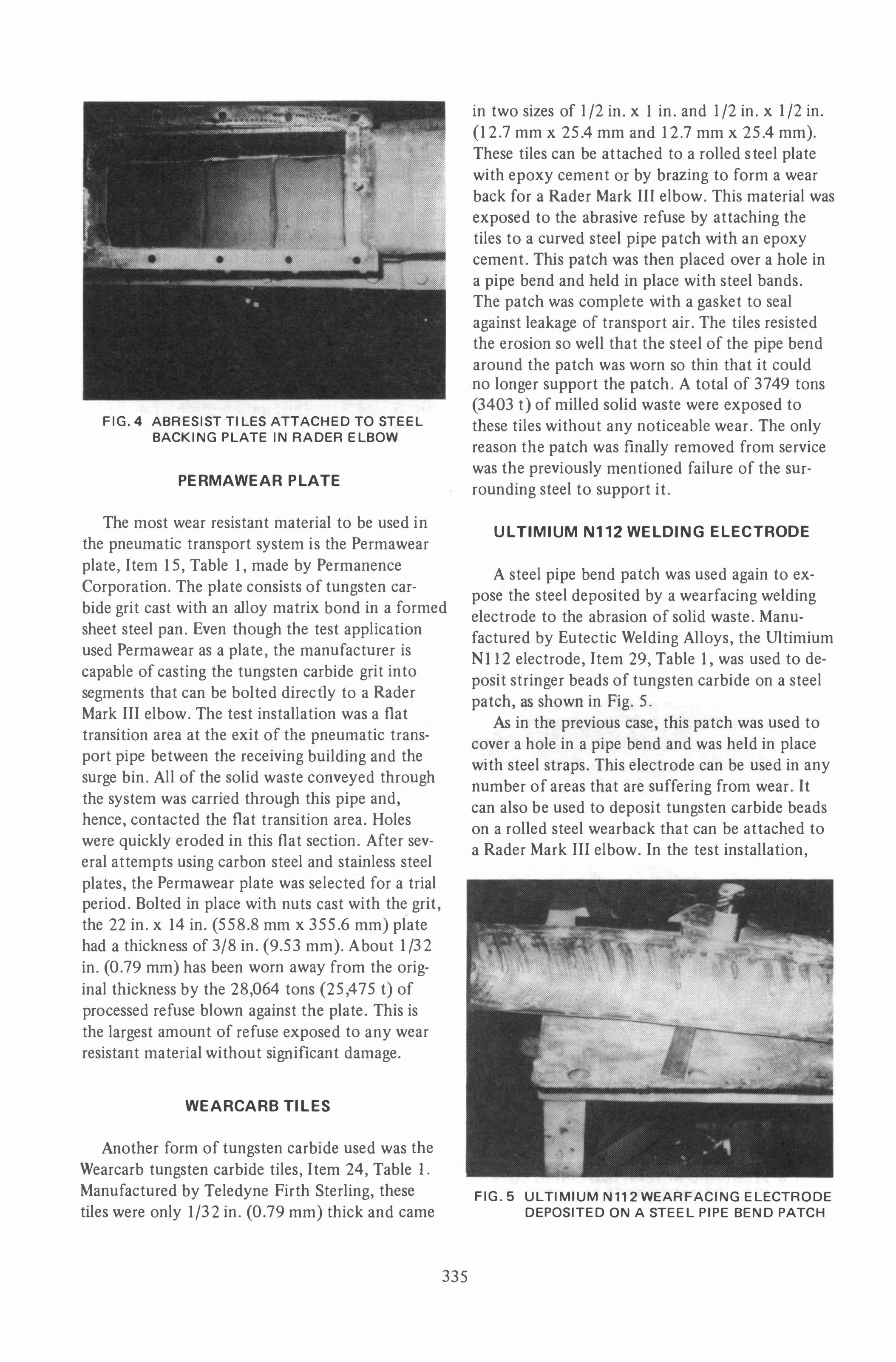
An excellent material for abrasion resistance is Abresist, a volcanic basalt rock, Item 19, Table 1. Cast as either flat tiles or contoured sections, this material can be used to line the wear back of a Rader Mark III elbow or it can be used to line the entire internal surface of a steel pipe bend.
Marketed in the United States by M. H. Detrick Co., this material is shown in the test installation using a Rader elbow in Fig. 4.
The tiles were attached to the steel backing plate with an epoxy cement supplied by Detrick that kept its bond throughout the test period.
About 1/8 in. (3.18 mm) was worn from the original thickness of 1� in. (31.75 mm) by the 3772 tons (3424 t) of refuse that were carried through the elbow. Most of the erosion was concentrated in the area where the wear back made the sharpest turn. This damage was probably due to the severe impact of the refuse as it changed direction.
Rader MARK III
elbow
PATENTED EXPANSION CHAMBER
SPACE REQ'D
less than other long radius elbows interchangeable with other elbows.
ELBOW RADIUS
."" -'
.. �.-t!I--+--
IMPACT SECTION
controls & collects material before changing direction designed to minimize wear 10· impact angle controls material damage replaceable
PATENTED
FIG. 3
334
INSPECTION DOOR
• replaceable
• AR plale (standard) • A-35 cast segments
• directs material to center of pipe
• Ni-hard cast segments • stainless steel • any available rolled �.te
WELDED BACK
AR plale (slandard) Mild steel plate for non-abrasive & noncorrosive applications
FIG. 4 ABRESIST TILES ATTACHED TO STEEL BACKING PLATE IN RADER ELBOW
PERMAWEAR PLATE
The most wear resistant material to be used in the pneumatic transport system is the Permawear plate, Item IS, Table I, made by Permanence Corporation. The plate consists of tungsten carbide grit cast with an alloy matrix bond in a formed sheet steel pan. Even though the test application used Permawear as a plate, the manufacturer is capable of casting the tungsten carbide grit into segments that can be bolted directly to a Rader
Mark III elbow. The test installation was a flat transition area at the exit of the pneumatic transport pipe between the receiving building and the surge bin. All of the solid waste conveyed through the system was carried through this pipe and, hence, contacted the flat transition area. Holes were quickly eroded in this flat section. After several attempts using carbon steel and stainless steel
plates, the Permawear plate was selected for a trial period. Bolted in place with nuts cast with the grit, the 22 in. x 14 in. (558.8 mm x 355.6 mm) plate had a thickness of 3/8 in. (9.53 mm). About 1/32
in. (0.79 mm) has been worn away from the orig
inal thickness by the 28,064 tons (25,475 t) of processed refuse blown against the plate. This is the largest amount of refuse exposed to any wear resistant material without Significant damage.
Manufactured by Teledyne Firth Sterling, these tiles were only 1/32 in. (0.79 mm) thick and came
335
in two sizes of 1/2 in. x I in. and 1/2 in. x 1/2 in. (12.7 mm x 25.4 mm and 12.7 mm x 25.4 mm). These tiles can be attached to a rolled steel plate with epoxy cement or by brazing to form a wear back for a Rader Mark III elbow. This material was exposed to the abrasive refuse by attaching the tiles to a curved steel pipe patch with an epoxy cement. This patch was then placed over a hole in a pipe bend and held in place with steel bands. The patch was complete with a gasket to seal against leakage of transport air. The tiles resisted the erosion so well that the steel of the pipe bend around the patch was worn so thin that it could no longer support the patch. A total of 3749 tons (3403 t) of milled solid waste were exposed to these tiles without any noticeable wear. The only reason the patch was finally removed from service was the previously mentioned failure of the surrounding steel to support it.
UL TIMIUM N112 WELDING ELECTRODE
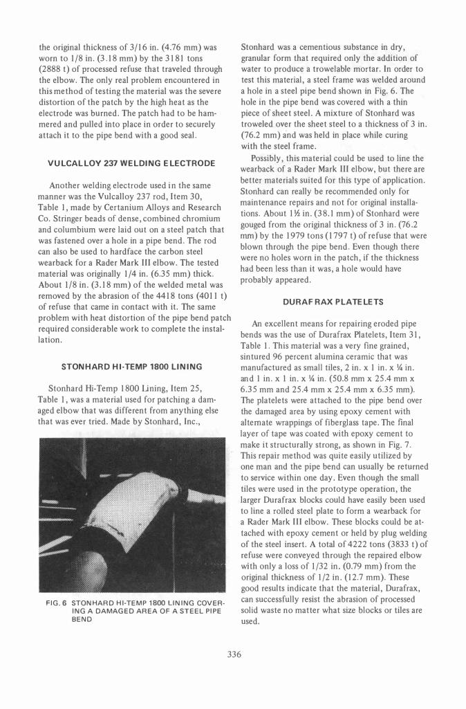
A steel pipe bend patch was used again to expose the steel deposited by a wearfacing welding electrode to the abrasion of solid waste. Manufactured by Eutectic Welding Alloys, the Ultimium NI12 electrode, Item 29, Table I, was used to de
posit stringer beads of tungsten carbide on a steel patch, as shown in Fig. 5.
As in the previous case, this patch was used to cover a hole in a pipe bend and was held in place with steel straps. This electrode can be used in any number of areas that are suffering from wear. It can also be used to deposit tungsten carbide beads on a rolled steel wearback that can be attached to a Rader Mark III elbow. In the test installation,
FIG.5 UL TIMIUM N112 WEARFACING ELECTRODE DEPOSITED ON A STEEL PIPE BEND PATCH
the original thickness of 3/16 in. (4.76 mm) was worn to 1/8 in. (3.18 mm) by the 3181 tons (2888 t) of processed refuse that traveled through the elbow. The only real problem encountered in this method of testing the material was the severe distortion of the patch by the high heat as the electrode was burned. The patch had to be hammered and pulled into place in order to securely attach it to the pipe bend with a good seal.
VULCALLOY 237 W ELDING ELECTROD E
Another welding electrode used in the same manner was the Vulcalloy 237 rod, Item 30, Table 1, made by Certanium Alloys and Research Co. Stringer beads of dense, combined chromium and columbium were laid out on a steel patch that was fastened over a hole in a pipe bend. The rod can also be used to hard face the carbon steel wearback for a Rader Mark III elbow. The tested material was originally 1/4 in. (6.35 mm) thick. About 1/8 in. (3.18 mm) of the welded metal was removed by the abrasion of the 4418 tons (4011 t) of refuse that came in contact with it. The same problem with heat distortion of the pipe bend patch required considerable work to complete the installation.
STONHARD HI-TEM P 1800 LINING
Stonhard Hi-Temp 1800 lining, Item 25, Table 1, was a material used for patching a damaged elbow that was different from anything else that was ever tried. Made by Stonhard, Inc.,
FIG.6 STONHARD HI-TEMP 1800 LINING COVER
ING A DAMAGED AREA OF A STEEL PIPE
BEND
Stonhard was a cementious substance in dry, granular form that required only the addition of water to produce a trowel able mortar. In order to test this material, a steel frame was welded around a hole in a steel pipe bend shown in Fig. 6. The hole in the pipe bend was covered with a thin piece of sheet steel. A mixture of Stonhard was troweled over the sheet steel to a thickness of 3 in. (76.2 mm) and was held in place while curing with the steel frame.
Possibly, this material could be used to line the wearback of a Rader Mark III elbow, but there are better materials suited for this type of application. Stonhard can really be recommended only for maintenance repairs and not for original installations. About I � in. (38.1 mm) of Stonhard were gouged from the original thickness of 3 in. (76.2 mm) by the 1979 tons (1797 t) of refuse that were blown through the pipe bend. Even though there were no holes worn in the patch, if the thickness had been less than it was, a hole would have probably appeared.
DURAFRAX PLATELETS
An excellent means for repairing eroded pipe bends was the use of Durafrax Platelets, Item 31, Table 1. This material was a very fine grained, sintured 96 percent alumina ceramic that was manufactured as small tiles, 2 in. x 1 in. x \4 in. and 1 in. x 1 in. x \4 in. (50.8 mm x 25.4 mm x 6.35 mm and 25.4 mm x 25.4 mm x 6.35 mm). The platelets were attached to the pipe bend over the damaged area by using epoxy cement with alternate wrappings of fiberglass tape. The final layer of tape was coated with epoxy cement to make it structurally strong, as shown in Fig. 7. This repair method was quite easily utilized by one man and the pipe bend can usually be returned to service within one day. Even though the small tiles were used in the prototype operation, the larger Durafrax blocks could have easily been used to line a rolled steel plate to form a wearback for a Rader Mark III elbow. These blocks could be attached with epoxy cement or held by plug welding of the steel insert. A total of 4222 tons (3833 t) of refuse were conveyed through the repaired elbow with only a loss of 1/32 in. (0.79 mm) from the original thickness of 1/2 in. (12.7 mm). These good results indicate that the material, Durafrax, can successfully resist the abrasion of processed solid waste no matter what size blocks or tiles are used.
336
'--FI BE R GLASS - E POX Y
'--DURAFRAX PLA TEL£TS
FIG.7 DURAFRAX PLATELETS ATTACHED TO STEEL PIPE BEND
ARLCITE BLOCKS
Another ceramic used to resist abrasion was the Arlcite alumina ceramic blocks, Item 32, Table 1, made by Ferro Electro Corporation, Refractories and Abrasives Division. Consisting of at least 85 percent sintered alumina, these blocks were at
tached with epoxy cement to a wearback that was fabricated by Meramec Plant personnel. This wearback was bolted to a rectangular box that was built into a damaged pipe at a 10 deg. mitred joint. This
box can be seen in Fig. 8. These blocks could also be easily attached to a wear back for a Rader Mark III elbow, like some of the other previously men
tioned materials. About 6409 tons (5818 t) of milled solid waste were blown against the Arlcite blocks with no measurable loss from the original thickness of 1 in. (25.4 mm). However, this application was not nearly as severe as the others previously discussed because the joint was only 10 deg. instead of 45 deg. or 90 deg. This 10 deg. joint greatly reduced the change of direction of the refuse steam, and thus reduced the abrasive wear.
The remaining two materials that will be discussed were installed shortly before the Energy Recovery Project was terminated. They both had a minimal amount of exposure with no detectable damage. Even so, these materials will be mentioned for informational purposes.
337
FIG.8 RECTANGULAR BOX BUILT INTO 10° MITRED PIPE JOINT, WITH WEAR BACK
REMOVED
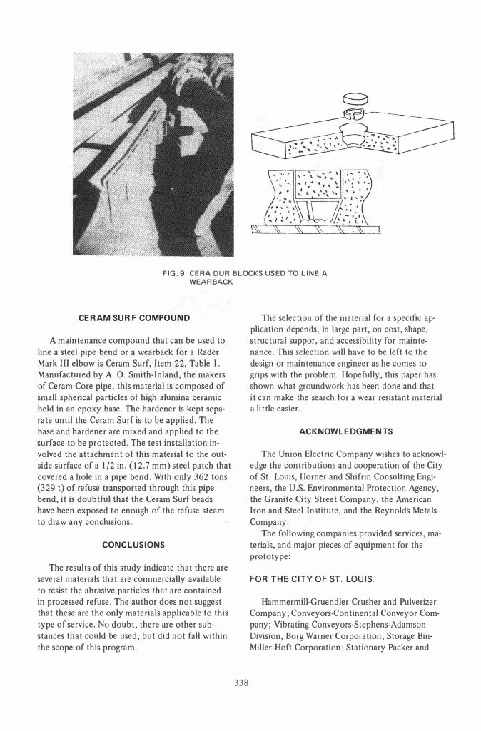
CERA OUR TILES
Cera Dur, Item 33, Table 1, is a ceramic produced by Dura Wear Corporation that is formed into tiles. Composed of 85 percent metallic oxide, this material can be attached to the rolled wearback of a Rader Mark III elbow by welding or with epoxy cements. Again, the test installation was a rectangular box built at a 10 deg. mitred joint in the
pneumatic pipeline, as shown in Fig. 9. The tiles
were anchored to the wearback by welding the steel insert to the steel plate. No material was re
moved by the 483 tons (438 t) of refuse that were impacted against the tiles.
FIG.9 CERA OUR BLOCKS USED TO LINE A
WEAR BACK
CERAM SURF COM POUND
A maintenance compound that can be used to line a steel pipe bend or a wearback for a Rader Mark III elbow is Ceram Surf, Item 22, Table l . Manufactured by A. O. Smith-Inland, the makers of Ceram Core pipe, this material is composed of small spherical particles of high alumina ceramic held in an epoxy base. The hardener is kept separate until the Ceram Surf is to be applied. The base and hardener are mixed and applied to the surface to be protected. The test installation involved the attachment of this material to the outside surface of a 1/2 in. (12.7 mm) steel patch that covered a hole in a pipe bend. With only 362 tons (329 t) of refuse transported through this pipe bend, it is doubtful that the Ceram Surf beads have been exposed to enough of the refuse steam to draw any conclusions.
CONCLUSIONS
The results of this study indicate that there are several materials that are commercially available to resist the abrasive particles that are contained in processed refuse. The author does not suggest that these are the only materials applicable to this type of service. No
, doubt, there are other sub
stances that could be used, but did not fall within the scope of this program.
338
The selection of the material for a specific application depends, in large part, on cost, shape, structural suppor, and accessibility for maintenance. This selection will have to be left to the design or maintenance engineer as he comes to grips with the problem. Hopefully, this paper has shown what groundwork has been done and that it can make the search for a wear resistant material a li ttle easier.
ACKNOWL EDGMENTS
The Union Electric Company wishes to acknowledge the contributions and cooperation of the City of St. Louis, Horner and Shifrin Consulting Engineers, the U.S. Environmental Protection Agency, the Granite Ci ty Street Company, the American Iron and Steel Institute, and the Reynolds Metals Company.
The following companies provided services, materials, and major pieces of equipment for the prototype:
FOR THE CITY OF ST. LOUIS:
Hammermill-Gruendler Crusher and Pulverizer Company; Conveyors-Continental Conveyor Company; Vibrating Conveyors-Stephens-Adamson Division, Borg Warner Corporation; Storage BinMiner-Hoft Corporation; Stationary Packer and
Transfer Trailers-Heil Corporation; Pneumatic
Transport Equipment and Air Classification
Equipment-Rader Pneumatics, Inc.; Magnetic
Metal "Nuggetizer"-Eidal Corporation.
FOR THE UNION ELECTRIC COMPANY:
Boilers-Combustion Engineering, InC.; Storage
Silo-Atlas Systems, Inc.; Pneumatic Transport Equipment-Rader Pneumatics, Inc.; Refuse and
Refuse Ash Analysis-Ralson Purina-Research 900;
Wear Resistant Materials-Goodyear Tire and Rub
ber Company, Devcon Corporation, Pecora Corporation, Nordberg Machinery Group-Rexnord, Inc., A. P. Green Company, Ruder Pneumatics, Inc., A. O. Smith-Inland Inc., Kinton Carbide, Permanence Corporation, C. E. RefractoriesCombustion Engineering, Inc., Air Reduction Company, Certanium Alloys and Research Company, Teledyne Firth Sterling, Stonhard, Inc.,
Eutectic Welding Alloys, Ferro Electro Corporation-Refractories and Abrasives Division, Car
borundum Company, M. H. Detrick Company,
Dura Wear Corporation.
REFERENCES
[ 1] Dreifke, Gerald E., Klumb, David L., and Smith,
Jerrel D., "Solid Waste as a Utility Fuel," Chicago;
American Power Conference, May 8-10, 1973. [2] Dille, Earl K., Klumb, David L., and Sutterfield,
G . Wayne, "Recycling Solid Waste for Utility Fuel and
Recovery of Other Resources," Oklahoma State Uni
versity Frontiers of Power Technology, October 10-11, 1973.
[3] Lowe, Robert A., Energy Recovery from Waste, Washington, D. C., U. S. Environmental Protection
Agency, 1973. [4] Klumb, David L., "Solid Waste Prototype for
Recovery of Utility Fuel and Other Resources," 1974 Air Pollution Control Association Annual Meeting,
Denver, Colorado, 1974. [5] Klumb, David L., and Wells, Earl M., "Develop'
ment of the Solid Waste Resource," First Annual UMR
MEC Conference on Energy Resources, April 25, 1974. [6] Klumb, David L., and Wells, Earl M., "A Solid
Waste Utilization System for St. Louis," 1974 Joint
Power Generation Conference, Miami Beach, Florida,
September 17, 1974.
Key Words
Materials Handling
Public Utility
Research
St. Louis
339
Discussion by
James W. Keller
Wisconsin Electric Power Co.
Oak Creek, Wisconsin
The author presents an extensive evaluation of the performance of abrasion resistant materials used in handling processed refuse. What this evaluation lacks in the way of insuring controlled or similar conditions for the materials tested is compensated for in the sheer number of materials tested.
The first 12 months of operation of the air classified refuse ACR (i.e., RDF) receiving, storage, and firing equipment at Wisconsin Electric Power Company's Oak Creek Power Plant has shown abrasion of pneumatic conveying lines somewhat comparable to that illustrated by the author.
The pneumatic conveying system used to retrieve refuse from the Atlas storage bin for firing in two 310 MW suspension fired steam generators at Oak Creek is composed of approximately 1800 ft (548 m) of nominal 10 in. (25.4 cm) diameter, schedule 40, low carbon steel, pipe. Rader Mark III elbows with cast R35 alloy steel replaceable wear backs are used at all changes of direction. Four Rader Model 09 diverting valves are used to direct refuse to either of the two furnaces.
By March of 1978, a total of 31 ,000 tons of refuse were handled at Oak Creek. This is approximately 7,700 tons per conveying line, at an average feed rate of 5 to 10 tons per hour per conveying line.
Fifty separate locations in the conveying system are periodically being measured with an ultrasonic device in an attempt to monitor wear rates. As of March, .1978 the highest amounts of wear are noted at several of the Mark III elbows that are mounted on their side. Holes wear through the unprotected lower side of the elbow. This is particularly true for such elbows installed at the ends of long, straight, horizontal runs of pipe where glass and other abrasives are allowed to drop out to the bottom of the pipe.New wear back segments with extensions to protect the elbow sides are to be
installed during June, 1978 in order to correct this problem.
The Rader Model 09 valves have shown high wear rates (30 percent reduction of wall thickness) as these are only made of low carbon steel. Abrasion resistant alternatives are being considered for these valves.
Straight horizontal pipe runs have shown a 10 to 12 percent reduction in wall thickness at the bottom of the pipe, and 3 to 6 percent reduction at the top of the pipe.
Wear of the R35 cast steel wear back plates for the Rader Mark III elbows has been generally less than 5 percent of the material thickness.
It is hoped that these brief comments can be a useful addition to the evaluation of abrasion resistant materials as presented in this paper.
AUTHOR'S REPLY
To James W. Keller
The Energy Recovery Project was conceived and constructed to be a low-cost simple system for firing refuse in an electric utility size boiler. One of the first problems that was encountered with the system was the rapid erosion of the transport pipe bends. Unfortunately, the construction of the system did not lend itself to controlled tests of materials to resist this erosion.
The main purpose of testing so many different materials was to find one that could be used as soon as possible within the system before its operation was terminated by the formal ending of the project. As.reported in my paper, several of these materials were found to be well suited to resisting refuse abrasion and were used extensively.
I am happy to see that even though the Energy Recovery Project in St. Louis has been terminated, one of the materials experimented with in our system has also proven to be highly wear-resistant to refuse abrasion at the Oak Creek Power Plant. I hope that additional work will be performed in testing these materials within other refuse handling systems around the country.