Mathematical representation of friction in metal forming analysis Citation for published version (APA): Ramaekers, J. A. H., & Kals, J. A. G. (1986). Mathematical representation of friction in metal forming analysis. (TH Eindhoven. Afd. Werktuigbouwkunde, Vakgroep Produktietechnologie : WPB; Vol. WPA0297). Eindhoven: Technische Hogeschool Eindhoven. Document status and date: Published: 01/01/1986 Document Version: Publisher’s PDF, also known as Version of Record (includes final page, issue and volume numbers) Please check the document version of this publication: • A submitted manuscript is the version of the article upon submission and before peer-review. There can be important differences between the submitted version and the official published version of record. People interested in the research are advised to contact the author for the final version of the publication, or visit the DOI to the publisher's website. • The final author version and the galley proof are versions of the publication after peer review. • The final published version features the final layout of the paper including the volume, issue and page numbers. Link to publication General rights Copyright and moral rights for the publications made accessible in the public portal are retained by the authors and/or other copyright owners and it is a condition of accessing publications that users recognise and abide by the legal requirements associated with these rights. • Users may download and print one copy of any publication from the public portal for the purpose of private study or research. • You may not further distribute the material or use it for any profit-making activity or commercial gain • You may freely distribute the URL identifying the publication in the public portal. If the publication is distributed under the terms of Article 25fa of the Dutch Copyright Act, indicated by the “Taverne” license above, please follow below link for the End User Agreement: www.tue.nl/taverne Take down policy If you believe that this document breaches copyright please contact us at: [email protected]providing details and we will investigate your claim. Download date: 03. Apr. 2020
Transcript
Mathematical representation of friction in metal forminganalysisCitation for published version (APA):Ramaekers, J. A. H., & Kals, J. A. G. (1986). Mathematical representation of friction in metal forming analysis.(TH Eindhoven. Afd. Werktuigbouwkunde, Vakgroep Produktietechnologie : WPB; Vol. WPA0297). Eindhoven:Technische Hogeschool Eindhoven.
Document status and date:Published: 01/01/1986
Document Version:Publisher’s PDF, also known as Version of Record (includes final page, issue and volume numbers)
Please check the document version of this publication:
• A submitted manuscript is the version of the article upon submission and before peer-review. There can beimportant differences between the submitted version and the official published version of record. Peopleinterested in the research are advised to contact the author for the final version of the publication, or visit theDOI to the publisher's website.• The final author version and the galley proof are versions of the publication after peer review.• The final published version features the final layout of the paper including the volume, issue and pagenumbers.Link to publication
General rightsCopyright and moral rights for the publications made accessible in the public portal are retained by the authors and/or other copyright ownersand it is a condition of accessing publications that users recognise and abide by the legal requirements associated with these rights.
• Users may download and print one copy of any publication from the public portal for the purpose of private study or research. • You may not further distribute the material or use it for any profit-making activity or commercial gain • You may freely distribute the URL identifying the publication in the public portal.
If the publication is distributed under the terms of Article 25fa of the Dutch Copyright Act, indicated by the “Taverne” license above, pleasefollow below link for the End User Agreement:www.tue.nl/taverne
Take down policyIf you believe that this document breaches copyright please contact us at:[email protected] details and we will investigate your claim.
MATHEMATICAL REPRESENTATION OF FRICTION IN METAL FORMING ANALYSIS
J.A.H. Ramaekers and J.A.G. Kals (1), Eindhoven University of Technology, Netherlands
As recently stress~ by Kalpak)an [lJ, Schey [2J and many other authors [3-8J the development of an improved friction model is an important in metal forming analysis. In the present study a fresh friction approach is suggested. It connects the friction shear stress not only with the normal stress but also with the relative displacement between tool and workpiece and the relative surface increase. The model presented is based on the physical conception of the friction phenomenon as described by Schey [2,4J, Wanheim [7J and Dautzenberg [B,9J. Connections wi~h the well known Coulomb model (TFr = pp) and the so called constant friction model (TFr = m 0F/13) are discussed. Theoretical findings are verified with experimental data from different tests. Although a few questions are still open, some progress in technical understanding of friction in forming tools could be achieved.
.1 ~ dr.ir. J.A.B. Ramaekers, Eindhoven University.of Technology, Department of Mechanical Engineering, Devision of Production Engineering and Automation, p .0. Box 513, 5600 MB EINDHOVEN • Netherlands.
C') r,ot fOld
1. INTRODOCTION.
Tbe iaport&nce and coaplexity of tribology in metal forming has recently been outlined by Kalpakjian [1] and Kawai-Dohda [6]. The present contribution is dedicated to the mathematical representation of friction under .ixed conditions.
Besides the well known Coulomb- and constant friction model an extended aodel, relating the friction shear stress to the nOlmal stress,tbe relative displacement between tool and workpiece and the increase of the nominal area of contact between tool and workpiece (surface-extension) is suggested. It is based on physical ideas as presented by many authors {for example [1-10] .
. Three plane strain foraing processes - upsetting, ironing and continuous sheet bending - served for the experimental support. The friction concept suggested explains a number of observations and covera aeveral often used notions of friction. Although more experience with the application is needed, some praktieal conclusions are already possible.
2. THE FRICTION MODEL.
normal stress + p .
real contact area Ar
friction stress .. TFr
displacement u ~
A nominal contact area
Fig. 2.1. Mixed film lubrication.
Tbe friction "chanis. considered is the mixed film lubrication (Fig. 2.1). ASSUming the shear strength of the entrapped lubricant negligible compared with to the shear strength TF of the boundary film/ the equilibrium of shear forces on a surface element A dictates:
(2.1 )
During a forming operation the shear strength TF of the boundary fila and tbe real contact aIea AI will continuously change. If an increase of these quantities with the normal stress p, the relative displaceaent u and the ·surfaee strain- (relative increase of the noainal surface) A/Ao is assu.ed. the following first approach could be defined:
1
(2.2)
where Ao is the initial nominal contact area.
The friction .odel expressed herewith will be examined by means of the plane strain foraing processes: ironing (u-shape), sheet bending and upsetting .. Because only forces were measured the mean values of the quantities are defined. Furthermore the friction hill in the upsetting test will be calculated with the aid of Eq. (2.2) and be coapared with the result from the Coulomb model
(2.3)
and the constant friction model
(2.4)
It can easily be seen that all the above mentioned dependencies have a physical background. The relative displacement, for exaaple, effects the surface roughness profile in a way that the tops are flattened. This results in an increasin9 real contact: area. The increase of the nominal contact area results in a
'decreasing fila thickness of the bound lubricant layer which likely effects its shear resistance.
3. PLANE STRAIN IRONING.
Se-1
Fig. 3.1. The plane strain ironing test.
Equilibriua conditions provide the relations between the friction force FFr and the noraal force FN and the tool forces Fp and FO (Fig. 3.1) respectively:
(3.1) FFr = 0.5 Fp cos a - FD sin a
(3.2) F. = 0.5 Fp sin a + FD cos a
Fivs. 3.2 and 3.3 show so.e experimental values from Eqs. (3.1) and (3.2) in conventional representations.
Fro. Figs. 3.2. and 3.3 it could be concluded that the Coulomb aodel is correct. Froa Fig. 3.3 it follows that the constant friction aodel is also usefull to some extent .
• In Fi9. 3.4 the representation according to Eq. (2.2) is given. The extended .odel see.s to be rather correct. From a practical point of view the constant friction model is more favourable because of its easier handling.
4~----------------------------------------~
+ +if
.. 2 ··t X )t
1(,.4 •• 0(-
• 5 • 10 )C.
15 .. 25 •
0~ ________ .L ________ ~L-________ .L ________ ~
o 10 20 I I 30 40 FN KN
Fig. 3.2. Friction force and normal force in the ironing test (see Table 1).
.. terial c n £0 ~ubricant w 50 Fig. N/_2 fmml rmml
o~----·--------------~,----.----__________ ~ ________ ~ o ~05
Fig. 3.4. the friction force FFr in relation with the displaceaent u, the increase of the contact area A/Ao and the normal load FN.
• 4. CONTINUOUS SHEET BENDING.
Fig. 4.1. Continuous sheet bending test.
A strip with width wand initial thickness So is pulled along a cylinder. A backpull Fb can be introduced to increase the normal pressure p. The test can be carried out in two different ways: with a fixed cylinder or with a freely rotating cylinder. In the first aode the influence of the double bending plus the friction is aeasured. In the second mode only the effect of the bending is ae.sured.
So the aean values of the normal pressure and the friction stress are obtained fro. the t"ollowing expressions:
(4. 1 )
(4.2)
F2 + Fb p - -tIi--:-~ a -.".w
T = (F f - Fb)f~xed - (F f - Fb)free Fra • 2.Q.w
When carrying out the test with only one cylinder and neglecting a ainor surface increase of the sheet (s, w = konst), according to Eq. (2.2) a linear relation between TFrm and Pm should be found. The results of the experiments are represented ill Fig. (4.2). However, the presumed connection with the displacement - U. = ~ .• /4 - is not confirmed with these experiments.
s .
(~l 10 !-
o 50 .l
'K 10 + 1.5 • 5 • 2.5
Fig. 4.2. Friction shear stress TFrm and normal pressure Pm in the sheet bending test.
5. PLANE STRAIN UPSETTING.
Fig. 5.1. Plane strain upsetting (£y= 0).
Grid .easure.ents showed that", with sufficient lubrication, plane sections re.ain plane. So with the help of the slab method it can be written:
substituting Eq. (2.2) it follows (see App. A):
.-2 . 1 1 b2 So .., (5.2) p = n 0F(1 + 2" ~) exp{l q 5 (5 - 1){1 - 4 (~),.))
whereas Coulo.bs ' law leads to:
(5.3) p = ~ OF (1 + ~ ~) exp{~ ~ (1
With the constant friction model Eq. (2.4) the expression:
Fi9.-5.2. The friction hills calculated according Lo Eqs_ (5.2), (S.l) and (5.4) repectively.
For an arbitrary case - F ::: 680 kN, of : 157 N/mm2, w ::: 50 mm, b = 30 .. , 5
9= 4 .. , an,d 5 ::: O.S mm - the calt~ulated friction
hills accordl.n9 to the equations (5.2), (5.3) and (5.4) an, represented in Fig. (5.2). The friction coefficients are: q = 0.4 a- 1, ~ = 0.027 and m ::: 0.1 respectively.
Apart froa the consideration that the MqM-curve (Eq. 5.2) seems to be the aost acceptable one, this kind of pressure profile is nearest to aeasured pressure distributions [16,17].
Froa a aeasured force - displacement diagram mean values fo the . noraal pressure, the friction stress, the displacement and the
increase of the noainal contact area can be achieved:
(5.5) Pa = ~ (5.6) tFra = 2 I (Pa - 2 n of'
(5.7) U.=t b (1 _ L)
So
(5.8) t:=~ o 5
,
•
0.04!o-
0.02
• ~
O~ ________ ~~·L-______ ~~ _________ ~· o 1 2 3
Pm/OF
Fig. 5.3. Friction stress TFrm in relation with the normal stress Pa during upsetting.
Fig. (5.3) shows some experimental values from Eq. (5.6) and (5.5) in a conventional representation. 80th the Coulomb and constant friction .ode'! are not in accordance wilh t.hesE" .easute.ents. In Fig. (5.4) the friction stress is given in relation with the present friction model. However thE' suggp.stpd dependency in Eq. (2.2) appears to be a nonlinear one .
0.0.
TFrm OF
0.04-
0.02 ,
•
. ? • ", .. •
•
----~ . ---• ---•
I~ I I • oa------------~~--------L __ ---------~~ o 50 100 150
Urn· A/Ao · Pm/OF
Fig. 5.4. Experiaental results of the upsetting test.
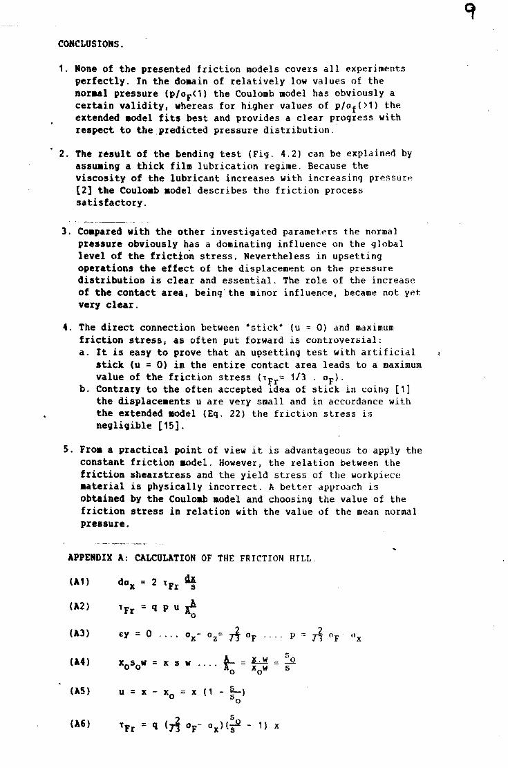
CONCLUSIONS.
1. None of the presented friction models covers all experiments perfectly. In the do.ain of relatively low values of the noraal pressure (P/oF<1) the Coulomb model has obviously a certain validity, whereas for higher values of p/of()1) the extended .odel fits best and provides a clear progress with respect to the predicted pressure distribution .
• 2. The result of the bending test (Fig. 4.2) can be explained by assu.ing a thick film lubrication regime. Because the viscosity of the lubricant increases with increasing pressure [2] the Coulo.b .odel describes the friction process satisfactory.
3. Co.pared with the other investigated parameters the normal pressure obviously has a dominating influence on the global level of the friction stress. Nevertheless in upsetting operations the effect of the displacement on the pressure distribution is clear and essential. The role of the increase of the contact area, being'the minor influence. became not y~t very clear.
4. The direct connection between ·stick- (u = 0) and maximum friction stress, as often put forward is controver~ial: a. It is easy to prove that an upsetting test with artificial
stick (u = 0) in the entire contact area leads to a maximum value of the friction stress (lFr= 1/3 . OF)'
b. Contrary to the often accepted idea of stick in coin!} [1] the displace.ents u are very small and in accordance with the extended aodel (Eq. 22) the friction stress is negligible [15].'
5. Froa a practical point of view it is advantageous to apply the constant friction &odel. However, the relation between the friction shearstress and the yield stress of the workpiece aaterial is physically incorrect. A better approach is obtained by the Couloab .odel and choosing the value of the friction stress in relation with the value of the mean normal pressure.
APPENDIX A: CALCULATION OF THE FRICTION HILL
(A1) dox = 2 tFr sa 5
(A2) lFr = q p ut 0
(A3) £oy = 0 °x- oz= rl- OF P ::: 2 OF Ox ..... n
(A4) xosow = x s w t:- -~ = 50
.... - x w s o 0
(AS) u = x - x = 0 x ( 1 _ L)
So
(A6) 1Fr = q (,; °F- ~ ox) (s - 1) x
Fro. (A1) to (A6) follows:
(A1) dox • 2 g (so _ 1) x dx 2/13 0,- Ox _. 5 5
The boundary condition for Ox can be calculated from:
s 1 . 0x(x=b/2) . ux (x=b/2) . 5 . W = b 7J OF Uz dz W
So:
(AB) 0x(x=b/2) = - rt of t Solvin9 Eq. (A1) leads to:
(A9) p = 1i of (1 + ~~) exp (t q b! (:0 - 1)(1 - 4 (t)2))
REFERENCES.
[1] lalpakjian, 5.: Recenmt Progress in Metal forming Tribology. Ann. CliP 34,2 (1985), 1-8.
[2] Schey, J.A.: Tribology. Handbook of Metal Forming, chapter 6; ed. K. Lange; Mc-Graw - Hill (1985).
[3] Bartz, V.J.; Volff, J.; eds.: pIoe. 3rd International Colloquiu. -Lubrication in Metal Working-. Esslingen (1982).
[4] Schey, J.1.: Metal Deformation Processes. M. Dekker (1970).
[5] Vilson, V.R.D.: Friction and Lubrication in sheet Metal For.in9i Mechanics of Sheet Metal Forming. p 157-177; eds. D.P. Koistinen and N.M. Vang; Plenum Press (1978).
[6] lawai, N. and K. Dohda: Tribology in Metal Forming Processes. Advanced Technology of Plasticity, p 145-156. Proc. 1e Int. Conf. Technol. Plast., Tokyo (1984).
[1] Grabener, Th.: Entwicklungen und Anwendung neuer Schaierstoffprufverfahren fiir die Kaltmassivumformung, Universitat Stuttgart. Springer Verlag (1QS1).
[8] Wanhei., T.; 9ay, N.: A Model for Friction in Metal Forming Processes. Ann. CLRP 27,1(1978), p. 189-194.
[9] Oautzenberg, J. H.: Reibung und Gleitverschliess bei ;. Trockenreibung. Ph.D. Thesis, Eindhoven University of Technolo~y, (1977).
[10] Oautzenberg, J.H.; Kals, J.A.G.: Metallverformung bei trockener Reibung. Zeitschrift fUr Metallkunde 79(1985), p. 635-639.
[11] Bay, N.: Tool/Workpiece Inferface in Cold Forward Extrusion. Advanced Technology of Plasticity, p259-266. Proc ."1e Intern. Conf. Technol. Plast. f Tokyo (1984).
[12] Nine, H.D.: Drawbead Forces in Sheet Metal Forming. Mechanics of Sheet Metal Forming, p179-21'. eds. D.P. Koistinen and N.M. Wang; Plenum Press (1978) .
. [131 Dautzenberg, J.H. and J.A.G. Kals; Stress :;tdte dnd Surfdce Roughness. Advanced Technology of Pla~ticity, p186-191; Proc.1st Int.Conf.Technol.Plast., Tokyo (1984).
[14] Raaaekers, J.A.H. and M.J.H. Smeets: Contactverschijnselen bi; het oavor.en (in Dutch). Metaalbewerking no. 3 (1984) pS4-58.
[15] Raaaekers, J.A.H. and S. Hoogenboom: The Prediction of Tool Pressures in Coining; Advances in Manufacturing Technology 1985; ed. P.P. Miller; Proc. 2nd Conf. I.M.C., Jordanstown (1985).
[16] De Jong, J.E.: Numerical Analysis of Metalforming Processes. Ph.D Thesis, Eindhoven University of Technology (lq8~).
[17] Bay, N. and G. Gerved: Friction and Pressure Distri bution in Disk Forging. 17th Int.Cold.Forging Group. Nagoya (1984).